

Page 1
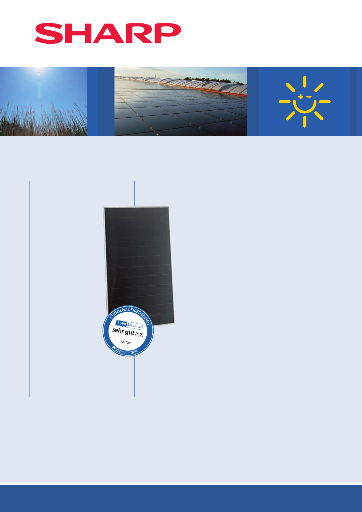
NA-Serie (1,42 m
135 W | 128 W | 121 W
Mikroamorphe Silizium-Dünnschicht-Photovoltaikmodule
Solarstrom – ja bitte!
Weil er das Klima schützt.
2
, 60 V)
Innovationen vom
Photovoltaikpionier
Als Solarspezialist mit 50
Jahren Erfahrung in der
Photovoltaik (PV) trägt
Sharp entscheidend zu wegweisenden Fortschritten in
der Solartechnologie bei.
Die Dünnschicht-Photovoltaikmodule der NA-Serie bestehen
aus einer amor phen und einer
mikrokristallinen Siliziumschicht.
Diese mikro amorphe Tandemstruktur absorbiert nicht nur
die sicht baren, sondern auch
die nicht sichtbaren Anteile des
Sonnen spektrums. Dies führt
zu einer besonders effektiven
Nutzung der Sonnenenergie.
Sämtliche Modultypen der Sharp NA-Serie
bieten technisch wie wirtschaftlich eine optimale Systemintegration und eignen sich für
die Montage in netzgekoppelten PV-Anlagen.
Produktmerkmale
■
Tandemstruktur aus einer amorphen und einer mikrokristallinen
Siliziumschicht mit einem stabilisierten Modulwirkungsgrad von
bis zu 9,5 %.
■
Optimiert für netzgekoppelte PV-Dachanlagen.
■
Verwendung von Weißglas, EVA-Kunststoff und Witterungsschutz-
folie sowie eines silber eloxierten Aluminiumrahmens für den Langzeiteinsatz. Dieser garantiert eine einfache und sichere Montage.
■
Modul kann von einer Person gehandhabt und montiert werden
(1,42 m2, Rahmenbreite 1 m, Gewicht 19 kg).
■
Höhere Energieerträge pro Watt sowohl bei hohen Temperaturen
als auch bei diffusem Licht.
■
Ausgang: Anschlusskabel mit wasser ge schütz tem Steckanschluss.
Qualität von Sharp
Der Qualitätsanspruch von Sharp Solar setzt Maßstäbe.
Ständige Kontrollen garantieren eine gleichbleibend hohe Qualität.
Jedes Modul wird optisch, mechanisch und elektrisch geprüft.
Sie erkennen es am Original Sharp Label, der Seriennummer und
der Sharp Garantie:
■
5 Jahre Produktgarantie
Kurzinformationen für den Installateur
■
Tandemstruktur aus einer amorphen und einer
mikrokristallinen Siliziumschicht
■
180 Zellen
■
2.400 N/m2 mechanische Belastbarkeit (245 kg/m2)
■
1.000 V DC maximale Systemspannung
■
IEC/EN 61646, IEC/EN 61730, Schutzklasse II (VDE: 40023069)
Deutschland: INFO-HOTLINE Mo.–Fr. von 8–20 Uhr 01805 / 01 52 22
Österreich: INFO-HOTLINE Mo.–Fr. von 8 –20 Uhr 0820 / 40 06 40 (0,145 € / Min.)
|
INFO-FAX 01805 / 38 32 38 (0,14 € / Min. aus dem deut schen Festnetz, ma x. 0,42 € / Min. aus dem deutschen Mobilfunknetz)
■
10 Jahre Leistungsgarantie auf eine Leistungsabgabe von 90 %
■
25 Jahre Leistungsgarantie auf eine Leistungsabgabe von 80 %
Die detaillierten Garantiebedingungen sowie weiterführende
Informationen erhalten Sie unter www.sharp.eu.
■
Zur Gewährung der Produkt- und Leistungsgarantie müssen die
Module durch den Endkunden bei Sharp registriert werden.
Die Registrierungsunterlagen werden vom Installateur oder direkt
von Sharp ausgehändigt.
|
INFO-FAX 0 8 2 0 / 2 4 6 2 5 9 (0,145 € / Min. aus dem Festnetz Österreichs, Anrufe aus dem Mobilfunknetz ggf. teurer)
Page 2
120
110
100
90
80
70
60
50
40
30
20
10
1.409
1.009
Strom (A)
Leistung (W)
Rahmen
Solarzelle
Anschlussbox
Leerlaufspannung V
oc
, I
sc
, P
m
(%)
140
120
100
80
60
40
20
0
400 (W/m2)
200 (W/m2)
600 (W/m
2
)
800 (W/m
2
)
1.000 (W/m
2
)
CC
10 20 30 40 6050
I
sc
V
oc
P
m
3,5
3,0
2,5
2,0
1,5
1,0
0,5
120
110
100
90
80
70
60
50
40
30
20
10
0
1.409
1.009
Rahmen
Solarzelle
Anschlussbox
Schraube
Anschlussbox
Leerlaufspannung V
oc
, I
sc
, P
m
(%)
CC
Unterstützungsschiene
I
sc
V
oc
P
m
120
110
100
90
80
70
60
50
40
30
20
10
0
1.409
1.009
Strom (A)
Leistung (W)
Rahmen
Solarzelle
Anschlussbox
Schraube
Steckanschluss
Anschlussbox
46
Glas
Seitliche
Abdichtung
Solarzelle
Rahmen
Hintere
Abdeckung
Kunst-
stoff
Leerlaufspannung V
oc
, I
sc
, P
m
(%)
140
120
100
80
60
40
20
0
400 (W/m2)
200 (W/m2)
600 (W/m
2
)
800 (W/m
2
)
1.000 (W/m
2
)
CC
Unterstützungsschiene
10 20 30 40 6050
I
sc
V
oc
P
m
Normalisierte Größen I
sc
, V
oc
, P
m
(%)
I
sc
V
oc
P
m
3,5
3,0
2,5
2,0
1,5
1,0
0,5
900 ±30900 ±30
74
1.409
1.009
504,5 8,0
CC
649,5 8,0
1.409
Rahmen
Solarzelle
Anschlussbox
Schraube
Steckanschluss
Anschlussbox
Glas
Seitliche
Abdichtung
Solarzelle
Rahmen
Hintere
Abdeckung
Kunst-
stoff
CC
Unterstützungsschiene
1.409
Rahmen
Solarzelle
Anschlussbox
Schraube
Steckanschluss
Anschlussbox
Glas
Seitliche
Abdichtung
Solarzelle
Rahmen
Hintere
Abdeckung
Kunst-
stoff
CC
Unterstützungsschiene
900± 30900± 30
74
74
1.409
1.009
Rahmen
Solarzelle
Anschlussbox
Schraube
Steckanschluss
Anschlussbox
46
CC
Unterstützungsschiene
Rahmen
Solarzelle
Anschlussbox
Schraube
Steckanschluss
Anschlussbox
Glas
Seitliche
Abdichtung
Solarzelle
Rahmen
Hintere
Abdeckung
Kunststoff
Mechanische Daten
Grenzwerte
Zelle
Zellenzahl und -verschaltung 180 Zellen (4 × 45 parallel)
Abmessungen 1.409 × 1.009 × 46 mm (1,42 m
Gewicht 19 kg
Anschlusstyp Kabel mit Steckanschluss (MC-3)
Bypass-Dioden 1
Tandemzelle aus amorphem (-Si) und
mikrokristallinem (c-Si) Silizium
2
)
Lagerungsluftfeuchtigkeit (rel.) bis 90 %
Betriebstemperatur (Zelle) – 40 bis + 90 °C
Lagerungstemperatur – 40 bis + 90 °C
Maximale Systemspannung 1.000 V DC
Maximale mechanische Belastung 2.400 N/m
Rückstrombelastbarkeit 5 A
Elektrische Daten
Anfangswerte Nominalwerte
NA-F135 (G5) NA-F128 (G5) NA-F121 (G5) NA-F135 (G5) NA-F128 (G5) NA-F121 (G5)
Nennleistung 158,9 W
Leerlaufspannung V
Kurzschlussstrom I
Spannung bei maximaler Leistung V
Strom bei maximaler Leistung I
Wirkungsgrad Modul
oc
sc
pm
pm
m
62,5 60,8 60,2 61,3 59,8 59,2 V
3,49 3,54 3,43 3,41 3,45 3,34 A
49,7 48,6 48,2 47 45,4 45 V
3,2 3,10 2,96 2,88 2,82 2,69 A
NOCT 44 44 44 °C
Temperatur-Koeffizient Leerlaufspannung
Temperatur-Koeffizient Kurzschlussstrom
Temperatur-Koeffizient Leistung
Die elektrischen Daten gelten bei Standard-Testbedingungen (STC): Einstrahlung 1.000 W/m2 mit Lichtspektrum AM 1,5 bei einer Zelltemperatur von 25 °C. Die unteren Leistungsabgaben unterliegen einer
Fertigungstoleranz von – 5 %. NOCT-Bedingungen: Einstrahlung von 800 W/m
V
l
P
– 0,30 – 0,30 – 0,30 – 0,30 – 0,30 – 0,30 % / °C
oc
+0,07 +0,07 +0,07 +0,07 +0,07 +0,07 % / °C
sc
– 0,24 – 0,24 – 0,24 – 0,24 – 0,24 – 0,24 % / °C
m
150,6 W
p
142,4 W
p
p
135 W
p
9,5 9,0 8,5 %
2
, Umgebungstemperatur von 20 °C und Windgeschwindigkeit von 1 m/sec.
128 W
p
121 W
p
2
Kennlinien NA-F135 (G5)
Kennlinien: Strom/Leistung über Spannung
Spannung (V) Strom über Spannung
(Zellentemperatur: 25 °C)
Leistung über Spannung
Außenabmessungen
Sharp Energy Solution Europe
a division of Sharp Electronics (Europe) GmbH
Sonninstrasse 3, 20097 Hamburg, Germany
Tel.: (040) 23 76-0 · Fax: (040) 23 76-2193
www.sharp.eu
Kennlinien: Leerlaufspannung/Kurzschlussstrom
und Maximalleistung über Einstrahlung
(Zellentemperatur: 25 °C)
2
)
Einstrahlung (W/m
Rückansicht
Kennlinien: Normalisierte Größen
Isc / Voc / P
über Zellentemperatur
m
Zellentemperatur (°C)
Landesvertretung:
Austria
SolarInfo.at@sharp.eu
Benelux
SolarInfo.seb@sharp.eu
Central & Eastern Europe
SolarInfo.scee@sharp.eu
Schnitt A-A’
Schnitt B-B’
Schnitt C-C’Anschlusskabel
Anwendungen
■
Netzgekoppelte PV-Anlagen
■
Aufdach-PV-Anlagen
■
Freiland-PV-Anlagen
Bitte lesen Sie vor der Montage der PhotovoltaikModule aufmerksam unsere ausführliche Montageanleitung. Den Anweisungen in der Montage anleitung
ist unbedingt Folge zu leisten (z. B. max. 13 Module in
Serie, Minus-Pol muss geerdet sein, Absicherung mit
Blockier-Dioden/Sicherungen).
Ein Generatorkasten mit freigege benen Blockier-Dioden
kann über Ihren Sharp Händler bezogen werden.
Hinweis
Änderungen der technischen Daten sind ohne vorherige Ankün di gung möglich. Bitte fordern Sie vor
der Verwendung von Sharp Produkten die aktuellsten
Daten blät ter von Sharp an. Sharp trägt keine Ver an t wortung für Schä den an Geräten, die anhand
von nicht abgesi cher ten Informa tio nen
bestückt wurden.
Produkten
Die Spezifikationen können geringfügig abweichen
und sind ohne Gewähr. Die Installations- und
Be triebsanleitungen sind den entsprechenden
Hand büchern zu entnehmen oder können unter
www.sharp.eu heruntergeladen werden.
Dieses Modul sollte nicht direkt mit einer Last verbunden werden.
Scandinavia
SolarInfo.sen@sharp.eu
Denmark
SolarInfo.dk@sharp.eu
France
SolarInfo.fr@sharp.eu
Germany
SolarInfo.de@sharp.eu
Spain & Portugal
SolarInfo.es@sharp.eu
Switzerland
SolarInfo.ch@sharp.eu
United Kingdom
SolarInfo.uk@sharp.eu
Das Referenzbild auf der Vorderseite zeigt eine 340 kWp große Sharp Dünnschichtanlage auf dem Fabrik-Dach der Firma Fliegl in Gera, Deutschland. Foto: AEP Energie-Consult GmbH
mit Sharp
So larN A_142 _D021 0
Page 3
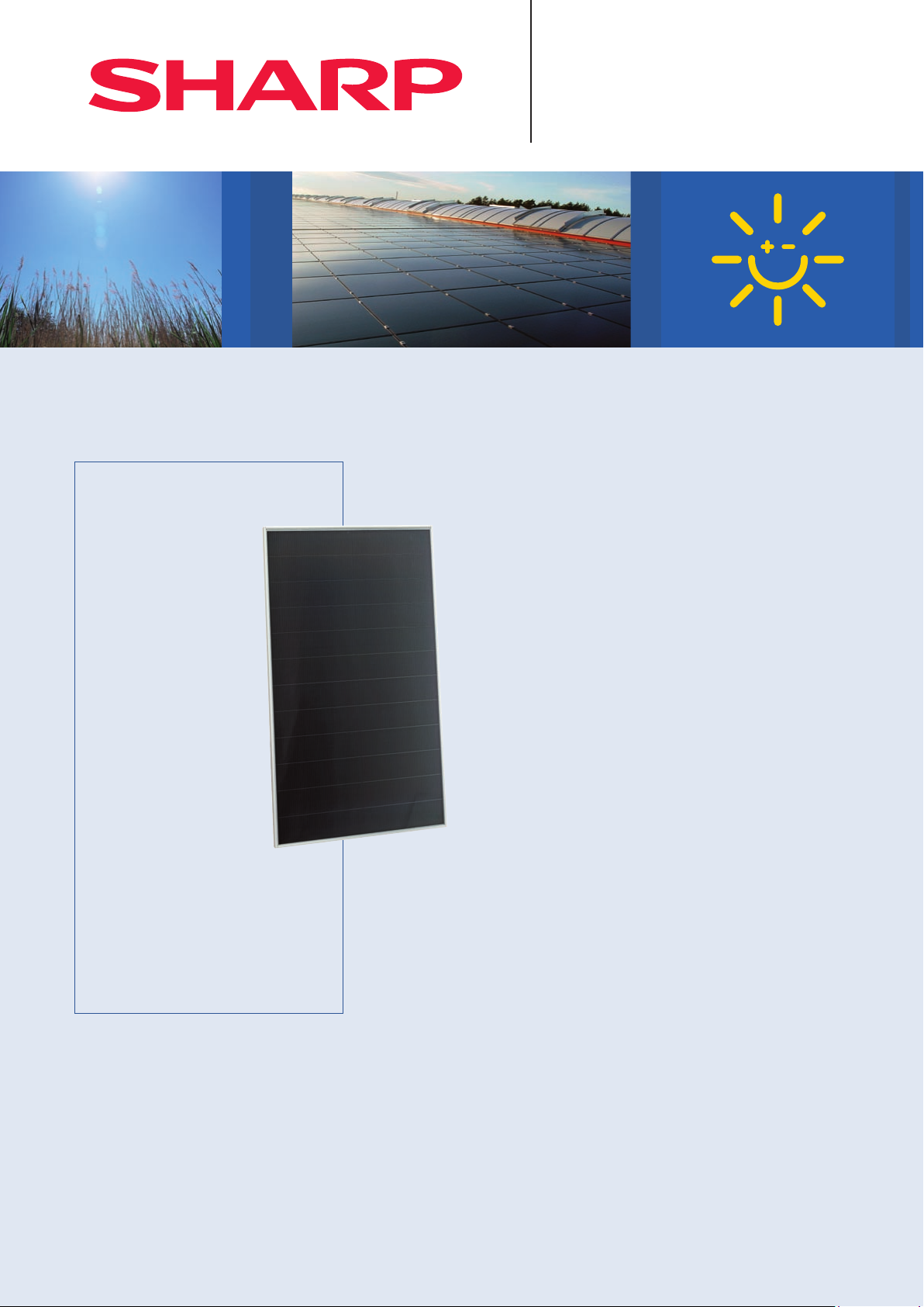
NA Series (1.42 m
135 W | 128 W | 121 W
Microamorphous silicon thin-film photovoltaic modules
Say yes to solar power!
Because it protects the climate.
2
, 60 V)
Innovations from a
photovoltaic pioneer
As a solar specialist with
50 years' experience in
photovoltaics (PV), Sharp
makes significant contributions to groundbreaking
progress in solar technology.
The NA series of thin-film
photovoltaic modules consists of an amorphous and a
microcrystalline silicon layer.
This microamorphous tandem
structure not only absorbs visible light but also the invisible
portion of the solar spectrum.
This makes especially efficient
use of solar energy.
All module types of the Sharp NA Series
offer optimum system integration, in
terms of both technology and economy,
and are suitable for installations in gridconnected PV systems.
Product features
■
Tandem structure with an amorphous and a microcrystalline silicon
layer offering a stabilised module efficiency of up to 9.5%.
■
Optimised for grid-connected roof mounting PV systems.
■
Use of white glass, EVA plastic and weather protection film
as well as a silver anodised aluminium frame for long-term use.
This guarantees simple and safe installation.
■
Module can be operated and installed by one person
(1.42 m2, frame width 1 m, weight 19 kg).
■
Higher energy yields per watt, at both high temperatures and with
diffuse light.
■
Output: connection cable with waterproof plug connector.
Quality from Sharp
Benchmarks are set by the quality standards of Sharp Solar.
Con tinual checks guarantee a consistently high level of quality.
Every module undergoes visual, mechanical, and electrical
inspection. This is recognisable by means of the original Sharp
label, the serial number, and the Sharp guarantee:
■
5 year product guarantee
■
10 year performance guarantee for a power output of 90%
Brief details for the installer
■
Tandem structure consisting of an amorphous
and a microcrystalline silicon layer
■
180 cells
■
2,400 N/m2 mechanical load-bearing capacity (245 kg/m2)
■
1,000 V DC maximum system voltage
■
IEC/EN 61646, IEC/EN 61730, Class II (VDE: 40023069)
■
25 year performance guarantee for a power output of 80%
The detailed guarantee conditions and additional information can
be found at www.sharp.eu.
■
End users are required to register the modules with Sharp in order
for the product and service warranty to be effective.
The registration documents will be handed out by the installation
staff or supplied directly by Sharp.
Page 4

120
110
100
90
80
70
60
50
40
30
20
10
1,409
1,009
Current (A)
Power (W)
Frame
Solar cell
Junction box
oc
, I
sc
, P
max
(%)
CC
I
sc
V
oc
P
max
10 20 30 40 6050
140
120
100
80
60
40
20
0
400 (W/m2)
200 (W/m2)
600 (W/m
2
)
800 (W/m
2
)
1,000 (W/m
2
)
3.5
3.0
2.5
2.0
1.5
1.0
0.5
120
110
100
90
80
70
60
50
40
30
20
10
0
1,409
1,009
Frame
Solar cell
Junction box
Screw
Junction box
Open-circuit voltage V
oc
, I
sc
, P
max
(%)
CC
Support rail
,
I
sc
V
oc
P
max
120
110
100
90
80
70
60
50
40
30
20
10
0
1,409
1,009
Current (A)
Power (W)
Frame
Solar cell
Junction box
Screw
Plug connector
Junction box
46
Glass
Side seal
Solar cell
Frame
Back cover
Plastic
Normalised values I
sc
, V
oc
, P
m
(%)
Open-circuit voltage V
oc
, I
sc
, P
max
(%)
CC
Support rail
,
I
sc
V
oc
P
max
10 20 30 40 6050
I
sc
V
oc
P
m
140
120
100
80
60
40
20
0
400 (W/m2)
200 (W/m2)
600 (W/m
2
)
800 (W/m
2
)
1,000 (W/m
2
)
3.5
3.0
2.5
2.0
1.5
1.0
0.5
900 ±30900 ±30
74
1,409
1,009
504.5 8.0
CC
649.5 8,0
1,409
Frame
Solar cell
Junction box
Screw
Plug connector
Junction box
Glass
Side seal
Solar cell
Frame
Back cover
Plastic
CC
Support rail
1,409
Frame
Solar cell
Junction box
Screw
Plug connector
Junction box
Glass
Side seal
Solar cell
Frame
Back cover
Plastic
CC
Support rail
900± 30900± 30
74
74
1,409
1,009
Frame
Solar cell
Junction box
Screw
Plug connector
Junction box
46
CC
Support rail
Frame
Solar cell
Junction box
Screw
Plug connector
Junction box
Glass
Side seal
Solar cell
Frame
Back cover
Plastic
Mechanical data
Limit values
Cell
Connection 180 cells (4 × 45 parallel)
Dimensions 1,409 × 1,009 × 46 mm (1.42 m
Weight 19 kg
Connection type Cable with plug connector (MC-3)
Bypass diodes 1
Tandem cell of amorphous (-Si) and
microcrystalline (c-Si) silicon
2
)
Storage air humidity (relative) up to 90 %
Operating temperature (cell) – 40 to + 90 °C
Storage temperature – 40 to + 90 °C
Maximum system voltage 1,000 V DC
Maximum mechanical load 2,400 N/m
Over-current protection 5 A
Electrical data
Initial values Nominal values
NA-F135 (G5) NA-F128 (G5) NA-F121 (G5) NA-F135 (G5) NA-F128 (G5) NA-F121 (G5)
Maximum power 158.9 W
Open-circuit voltage V
Short-circuit current I
Voltage at point of maximum power V
Current at point of maximum power I
Module efficiency
oc
sc
pm
pm
m
62.5 60.8 60.2 61.3 59.8 59.2 V
3.49 3.54 3.43 3.41 3.45 3.34 A
49.7 48.6 48.2 47 45.4 45 V
3.2 3.10 2.96 2.88 2.82 2.69 A
NOCT 44 44 44 °C
Temperature coefficient – open-circuit voltage
Temperature coefficient – short-circuit current
Temperature coefficient – power
The electrical data applies under standard test conditions (STCs): irradiation 1,000 W/m2 with light spectrum AM 1.5 and a cell temperature of 25 °C. The rated electrical characteristics are subject to a manufacturing
lower tolerance of – 5%. NOCT conditions: irradiation of 800 W/m
V
l
P
– 0.30 – 0.30 – 0.30 – 0.30 – 0.30 – 0.30 % / °C
oc
+0.07 +0.07 +0.07 +0.07 +0.07 +0.07 % / °C
sc
– 0.24 – 0.24 – 0.24 – 0.24 – 0.24 – 0.24 % / °C
m
2
, ambient temperature of 20 °C and wind speed of 1 m/sec.
150.6 W
p
142.4 W
p
p
135 W
p
128 W
p
121 W
p
9.5 9.0 8.5 %
2
Characteristic curves NA-F135 (G5)
Characteristic curves: current / power vs. voltage
Voltage (V) Current vs. voltage
(cell temperature: 25 °C)
Power vs. voltage
Exterior dimensions
Tel: + 49 (0) 40 / 23 76 - 0 · Fax: + 49 (0) 40 / 23 76 - 21 93
Sharp Energy Solution Europe
a division of Sharp Electronics (Europe) GmbH
Sonninstrasse 3, 20097 Hamburg, Germany
www.sharp.eu
Characteristic curves: open-circuit voltage / shortcircuit current and maximum power vs. irradiation
(cell temperature: 25°C)
Irradiance (W/m2)
Rear view
Characteristic curves: nor malised values
Isc / Voc / P
vs. cell temperature
max
Cell temperature (°C)
Cross-section A-A’
Cross-section B-B’
Cross-section C-C’Connection cable
Local responsibility:
Austria
SolarInfo.at@sharp.eu
Benelux
SolarInfo.seb@sharp.eu
Central & Eastern Europe
SolarInfo.scee@sharp.eu
Applications
■
On-grid PV systems
■
On-roof PV systems
■
Ground-mounted PV systems
Please read our detailed installation manual carefully
before installing the photovoltaic modules. The
instructions in the installation manual must always
be observed (e. g. max. of 13 modules in series, minus
pole must be grounded, protection with blocking
diodes/fuses).
A generator box with approved blocking diodes is
available from your Sharp dealer.
Note
Technical data is subject to change without prior
notice. Before using Sharp products, please request
the latest data sheets from Sharp. Sharp accepts
no responsibility for damage to devices which have
been equipped with Sharp products on the basis of
unverified information.
The specifications may deviate slightly and are not
guaranteed. Installation and operating instructions
are to be found in the corresponding handbooks, or
can be downloaded from www.sharp.eu.
This module should not be directly connected to
a load.
Scandinavia
SolarInfo.sen@sharp.eu
Denmark
SolarInfo.dk@sharp.eu
France
SolarInfo.fr@sharp.eu
Germany
SolarInfo.de@sharp.eu
Spain & Portug al
SolarInfo.es@sharp.eu
Switzerland
SolarInfo.ch@sharp.eu
United Kingdom
SolarInfo.uk@sharp.eu
The photo on the front page shows a 340 kWp-capacity thin film system on the roof at commercial vehicle manufacturer Fliegl’s production facilities near Gera, Germany. Photo: AEP Energie-Consult GmbH
So larN A_142 _E0210
Page 5

Serie NA (1,42 m
135 W | 128 W | 121 W
Módulos fotovoltaicos microamorfos de capa fina de silicio
Energía solar – ¡claro que sí!
Porque protege el clima.
2
, 60 V)
Innovaciónes de la empresa
líder en fotovoltaica
Como especialista con
50 años de experiencia
en la fotovoltaica (FV),
Sharp contribuye de forma
decisiva al desarrollo de la
tecnología solar.
Los módulos fotovoltaicos de
capa fina de la serie NA se
componen de una capa de
silicio amorfo y otra de microcristalino. Esta estructura microamorfa en tándem absorve
tanto los componentes visibles
como los invisibles del espectro
solar, con lo que se aprovecha
la energía del solar con mayor eficiencia.
Todos los tipos de módulos Sharp de la
serie NA ofrecen una óptima integración
de sistema a nivel técnico y económico y
resultan idóneos para el montaje en sistemas FV conectados a la red.
Características del producto
■ Estructura en tándem de una capa de silicio amorfo y otra
de microcristalino con un coeficiente del módulo estabilizado
hasta 9,5 %.
■ Optimizado para sistemas FV en tejado conectados a la red.
■ Utilización de vidrio blanco, plástico EVA y lámina resistente a
la intemperie, así como un marco de aluminio anodizado plata
para la utilización a largo plazo. Este marco garantiza el montaje
sencillo y seguro.
■ El módulo puede ser manejado y montado por una persona
(1,42 m2, anchura del marco: 1 m, peso 19 kg).
■ Gran rendimiento energético por vatio tanto a altas temperaturas
como con luz difusa.
■Salida: cable de conexión con conector estanco.
Calidad de Sharp
Los estándares de calidad de Sharp Solar marcan pautas.
Continuos controles garantizan una calidad duradera.
Todos los módulos son sometidos a ensayos ópticos,
mecánicos y eléctricos. Los reconocerá por la etiqueta original
de Sharp, el número de serie y la garantía de Sharp:
Información abreviada para el instalador
■
Estructura en tándem de una capa de silicio amorfa y
otra microcristalina
■
180 células
■
Capacidad de carga máxima de 2.400 N/m2 (245 kg/m2)
■
Tensión máxima del sistema 1.000 V CC
■
IEC/EN 61646, IEC/EN 61730, Clase II (VDE: 40023069)
■5 años de garantía al producto
■10 años garantía de rendimento al 90 % de la potencia
■25 años garantía de rendimento al 80 % de la potencia
Para más información y condiciones detalladas de garantía,
consulten www.sharp.eu.
■La garantía de producto y potencia únicamente será válida si el
cliente final registra los módulos en Sharp. La documentación
para el registro será facilitada por el instalador o directamente
por Sharp.
Page 6

120
110
100
90
80
70
60
50
40
30
20
10
1.409
1.009
Corriente (A)
Potencia (W)
Marco
Célula solar
Caja de
conexión
Tensión en circuito abierto
V
oc
, I
sc
, P
máx
(%)
CC
I
sc
V
oc
P
máx
140
120
100
80
60
40
20
0
400 (W/m2)
200 (W/m2)
600 (W/m
2
)
800 (W/m
2
)
1.000 (W/m
2
)
10 20 30 40 6050
3,5
3,0
2,5
2,0
1,5
1,0
0,5
120
110
100
90
80
70
60
50
40
30
20
10
0
1.409
1.009
Marco
Célula solar
Caja de
conexión
Tornillo
Caja de conexión
Tensión en circuito abierto
V
oc
, I
sc
, P
máx
(%)
CC
Barra de refuerzo
I
sc
V
oc
P
máx
120
110
100
90
80
70
60
50
40
30
20
10
0
1.409
1.009
Corriente (A)
Potencia (W)
Marco
Célula solar
Caja de
conexión
Tornillo
Conector
Caja de conexión
46
Vidrio
Sellado
lateral
Célula solar
Marco
Cubierta trasera
Plástico
Magnitudes normalizadas
I
sc
, V
oc
, P
m
(%)
Tensión en circuito abierto
V
oc
, I
sc
, P
máx
(%)
CC
Barra de refuerzo
I
sc
V
oc
P
máx
I
sc
V
oc
P
m
140
120
100
80
60
40
20
0
400 (W/m2)
200 (W/m2)
600 (W/m
2
)
800 (W/m
2
)
1.000 (W/m
2
)
10 20 30 40 6050
3,5
3,0
2,5
2,0
1,5
1,0
0,5
900 ±30900 ±30
74
1.409
1.009
504,5 8,0
CC
649,5 8,0
1.409
Marco
Célula solar
Caja de
conexión
Tornillo
Conector
Caja de conexión
Vidrio
Sellado
lateral
Célula solar
Marco
Cubierta trasera
Plástico
CC
Barra de refuerzo
1.409
Marco
Célula solar
Caja de
conexión
Tornillo
Conector
Caja de conexión
Vidrio
Sellado
lateral
Célula solar
Marco
Cubierta trasera
Plástico
CC
Barra de refuerzo
900± 30900± 30
74
74
1.409
1.009
Marco
Célula solar
Caja de
conexión
Tornillo
Conector
Caja de conexión
46
CC
Barra de refuerzo
Marco
Célula solar
Caja de
conexión
Tornillo
Conector
Caja de conexión
Vidrio
Sellado
lateral
Célula solar
Marco
Cubierta trasera
Plástico
Datos mecánicos
Valores límite
Célula
Número y conexión de células 180 células (4 × 45 paralelo)
Dimensiones 1.409 × 1.009 × 46 mm (1,42 m
Peso 19 kg
Tipo de conexión Cable con conector (MC-3)
Diodos de bypass 1
Célula tándem de silicio amorfo (-Si)
y microcristalino (c-Si)
2
)
Humedad (relativa) del aire en almacén hasta 90 %
Temperatura de funcionamiento (célula) - 40 hasta + 90 °C
Temperatura en almacén - 40 hasta + 90 °C
Tensión máxima del sistema 1.000 V CC
Capacidad de carga máxima 2.400 N/m
Corriente inversa máxima 5 A
Datos eléctricos
Valores iniciales Valores nominales
NA-F135 (G5) NA-F128 (G5) NA-F121 (G5) NA-F135 (G5) NA-F128 (G5) NA-F121 (G5)
Potencia nominal 158,9 W
Tensión en circuito abierto V
Corriente de cortocircuito I
Tensión en el punto de máxima potencia V
Corriente en el punto de máxima potencia I
Coeficiente de rendimiento del módulo
pm
pm
62,5 60,8 60,2 61,3 59,8 59,2 V
oc
3,49 3,54 3,43 3,41 3,45 3,34 A
sc
49,7 48,6 48,2 47 45,4 45 V
3,2 3 ,10 2,96 2,88 2,82 2,69 A
m
NOCT 44 44 44 °C
Coeficiente de temperatura – tensión en circuito abierto
Coeficiente de temperatura / corriente de cortocircuito
Coeficiente de temperatura potencia
Valores eléctricos se refieren a condiciones de prueba estándar (STC): Irradiación de 1.000 W/m2 con espectro de luz AM 1.5 a una temperatura de célula de 25 °C. La entrega de potencia está sujeta a una tolerancia
inferior de fabricación de - 5 %. Condiciones NOCT: irradiación de 800 W/m
V
l
P
- 0,30 - 0,30 - 0,30 - 0,30 - 0,30 - 0,30 % / °C
oc
+0,07 +0,07 +0,07 +0,07 +0,07 +0,07 % / °C
sc
- 0,24 - 0,24 - 0,24 - 0,24 - 0,24 - 0,24 % / °C
m
2
, temperatura ambiente de 20 °C y velocidad del viento de 1 m/sec.
150,6 W
p
142,4 W
p
135 W
p
128 W
p
121 W
p
p
9,5 9,0 8,5 %
2
Curvas características NA-F135 (G5)
Curvas características:
Corrien te / potencia e n función de la tensión
(temper atura de célu la: 25 °C)
Tensión (V) Corriente en función de la tensión
Potencia en función de la tensión
Curvas características: Tensión en circuito
abierto / corriente de cortocircuito y potencia
máxima en función de la irradiación
(temper atura de célu la: 25 °C)
Irradiación (W/m
Dimensiones exteriores
Tel: + 49 (0) 40 / 23 76 - 0 · Fax: + 49 (0) 40 / 23 76 - 21 93
Sharp Energy Solution Europe
a division of Sharp Electronics (Europe) GmbH
Sonninstrasse 3, 20097 Hamburg, Germany
www.sharp.eu
2
)
Vista trasera
Curvas características:
Valore s Isc / Voc / P
función de la temperatura de las células
m
Temperatura de las células (°C)
Responsabilidad local:
Austria
SolarInfo.at@sharp.eu
Benelux
SolarInfo.seb@sharp.eu
Central & Eastern Europe
SolarInfo.scee@sharp.eu
normalizados en
Sección A-A’
Sección B-B’
Sección C-C’Cable de conexión
Aplicaciones
■
Instalaciones FV conectadas a la red
■
Instalaciones FV sobre tejado
■
Instalaciones FV en campo abierto
Antes de montar los módulos fotovoltaicos, lea por
favor con atención nuestras instrucciones de montaje
detalladas. Siga las instrucciones al pie de la letra
(p. ej. máx. 13 módulos en serie, el polo negativo debe
estar conectado a tierra, protección con fusibles/diodos de bloqueo).
Puede adquirir una caja de generador con diodos de
bloqueo autorizados en su distribuidor Sharp.
Nota
Los datos técnicos pueden ser modificados sin previo
aviso. Rogamos solicite a Sharp las hojas de datos
ac tual es an tes d e uti liza r un p rodu cto de Sha rp. S har p
no se responsabiliza de daños en equipos que han sido
dotados con productos de Sharp sin la consulta previa
a una fuente de información segura.
Las especificaciones pueden variar ligeramente y no son
garantizadas. Encontrará las instrucciones de instalación
y op era ción en lo s man uale s cor resp ond ient es o p odrá
descargarlas de www.sharp.eu.
Este módulo no debería conectarse directamente a
una carga.
Scandinavia
SolarInfo.sen@sharp.eu
Denmark
SolarInfo.dk@sharp.eu
France
SolarInfo.fr@sharp.eu
Germany
SolarInfo.de@sharp.eu
Spain & Portug al
SolarInfo.es@sharp.eu
Switzerland
SolarInfo.ch@sharp.eu
United Kingdom
SolarInfo.uk@sharp.eu
La portada muestra un sistema de capa fina de 340 kWp de Sharp en el tejado de la fábrica de la empresa Fliegl en Gera (Alemania). Foto: AEP Energie-Consult GmbH
SolarNA_142_S0210
Page 7

Série NA (1,42 m
135 W | 128 W | 121 W
Modules photovoltaïques en couches minces de silicium micromorphe
Dites oui à l'énergie solaire !
Pour la protection du climat.
2
, 60 V)
Les innovations d'un pionnier
du photovoltaïque
Grâce à ses 50 ans d'ex périence dans le domaine du
photovoltaïque (PV), Sharp
contribue de manière significative aux progrès de la technologie solaire.
Les modules photovoltaïques en
couches minces de la série NA
sont com posés d'une couche de
silicium amorphe et d'une couche de silicium microcristallin.
Cette structure tandem micromorphe absorbe non seulement
les rayons visibles, mais aussi
les rayons invisibles du spectre
solaire. Cela permet une utilisation particulièrement efficace de l'énergie solaire.
Tous les modules de la série NA de Sharp
permettent une intégration optimale des
systèmes, tant du point de vue technique
qu'économique, et conviennent bien pour
le montage dans des installations photovoltaïques couplées au secteur.
Caractéristiques du produit
■
Structure tandem composée d'une couche de silicium amorphe
et d'une couche de silicium microcristallin qui permet d'obtenir
un rendement stabilisé du module pouvant atteindre 9,5 %.
■
Optimal pour les grandes installations PV raccordées au réseau.
■
Utilisation d'un verre blanc, de plastique EVA, d'un film protecteur
résistant aux intempéries et d'un cadre en aluminium anodisé
argenté avec perforations de drainage afin d'assurer la durabilité
et la facilité de montage des modules.
■
Chaque module peut aisément être manipulé et installé par une
seule personne (1,42 m2, largeur du cadre 1 m, poids 19 kg).
■
Meilleure production d'énergie par watt, aussi bien sous des
températures élevées que sous lumière diffuse.
■
Sortie : câble de raccordement avec connecteur résistant à l'eau.
La qualité Sharp
Les standards de qualité de Sharp sont une référence en matière
de technologie solaire. Des contrôles continus garantissent en permanence un haut niveau de qualité. Chaque module photovoltaïque
est soumis à un contrôle visuel, mécanique et électrique. Cette
qualité de fabrication est identifiable par le biais de l'étiquette
Sharp, du numéro de série et de la garantie Sharp :
■
Garantie produit de 5 ans
■
Garantie de performance de 10 ans pour une puissance de 90 %
Données sommaires pour l'installateur
■
Structure tandem composée d'une couche de silicium
amorphe et d'une couche de silicium microcristallin
■
180 cellules
■
Résistance mécanique de 2 400 N/m2 (245 kg/m2)
■
Tension maximale du système de 1 000 V CC
■
IEC/EN 61646, IEC/EN 61730, Classe II (VDE : 40023069)
■
Garantie de performance de 25 ans pour une puissance de 80 %
Pour connaître en détail nos conditions de garantie et obtenir des
informations complémentaires, veuillez consulter notre site Internet
www.sharp.eu.
■
Pour que le client final puisse bénéficier de la garantie produit
et de la garantie de performance, il devra enregistrer les modules
auprès de Sharp. Les documents d'enregistrement lui seront
remis par l'installateur ou bien directement par Sharp.
Page 8

120
110
100
90
80
70
60
50
40
30
20
10
1 409
1 009
Cadre
Cellule
Boîte de
raccordement
CC
I
sc
V
oc
Courant (A)
Puissance (W)
P
max
Tension à vide V
oc
, I
sc
, P
max
(%)
10 20 30 40 6050
140
120
100
80
60
40
20
0
400 (W/m2)
200 (W/m2)
600 (W/m
2
)
800 (W/m
2
)
1000 (W/m
2
)
3,5
3,0
2,5
2,0
1,5
1,0
0,5
120
110
100
90
80
70
60
50
40
30
20
10
0
1 409
1 009
Cadre
Cellule
Boîte de
raccordement
Vis
Boîte de raccordement
CC
Barre de soutien
I
sc
V
oc
P
max
Tension à vide V
oc
, I
sc
, P
max
(%)
120
110
100
90
80
70
60
50
40
30
20
10
0
1 409
1 009
Cadre
Cellule
Boîte de
raccordement
Vis
Connecteur
Boîte de raccordement
46
CC
Barre de soutien
I
sc
V
oc
Courant (A)
Puissance (W)
P
max
Tension à vide V
oc
, I
sc
, P
max
(%)
Valeurs normalisées I
sc
, V
oc
, P
max
(%)
Joint
latéral
Cadre
Verre
Cellule
Revêtement
arrière
Matière
plastique
900 ±30900 ±30
74
I
sc
V
oc
P
m
10 20 30 40 6050
140
120
100
80
60
40
20
0
400 (W/m2)
200 (W/m2)
600 (W/m
2
)
800 (W/m
2
)
1000 (W/m
2
)
3,5
3,0
2,5
2,0
1,5
1,0
0,5
1 409
1 009
504,5 8,0
CC
649,5 8,0
1 409
Cadre
Cellule
Boîte de
raccordement
Vis
Connecteur
Boîte de raccordement
CC
Barre de soutien
Joint
latéral
Cadre
Verre
Cellule
Revêtement
arrière
Matière
plastique
1 409
Cadre
Cellule
Boîte de
raccordement
Vis
Connecteur
Boîte de raccordement
CC
Barre de soutien
Joint
latéral
Cadre
Verre
Cellule
Revêtement
arrière
Matière
plastique
900± 30900± 30
74
74
1 409
1 009
Cadre
Cellule
Boîte de
raccordement
Vis
Connecteur
Boîte de raccordement
46
CC
Barre de soutien
Cadre
Cellule
Boîte de
raccordement
Vis
Connecteur
Boîte de raccordement
Joint
latéral
Cadre
Verre
Cellule
Revêtement
arrière
Matière
plastique
Caractéristiques mécaniques
Valeurs limites
Cellule
Nombre de cellules
et type de connexion
Dimensions 1 409 × 1 009 × 46 mm (1,42 m
Poids 19 kg
Type de sortie Câble avec connecteur (MC-3)
Diodes bypass 1
Cellule tandem composée de silicium amorphe
(-Si) et de silicium microcristallin (c-Si)
180 cellules (4 × 45 parallèle)
2
)
Humidité (relative) de stockage jusqu'à 90 %
Température de fonctionnement (cellules) – 40 à +90 °C
Température de stockage – 40 à + 90 °C
Tension maximale du système 1 000 V CC
Résistance mécanique maximale 2 400 N/m
Courant inverse 5 A
Caractéristiques électriques
Valeurs initiales Valeurs nominales
NA-F135 (G5) NA-F128 (G5) NA-F121 (G5) NA-F135 (G5) NA-F128 (G5) NA-F121 (G5)
Puissance maximale P
Tension à vide V
Courant de court-circuit I
Tension au point de puissance maximale V
Courant au point de puissance maximale I
Rendement du module
NOCT 44 44 44 °C
Coefficient de température – tension à vide
Coefficient de température – courant de court-circuit
Coefficient de température – puissance
Caractéristiques électriques mesurées selon les conditions de test standardisées (STC) : ensoleillement de 1 000 W/m2, masse atmosphérique de 1,5, température des cellules de 25 °C. Les caractéristiques de puissance sont
donnée s avec une to lérance de fa brication in férieure de – 5 %. Conditions NOCT : enso leillement d e 800 W/m
P
max
mpp
mpp
V
l
158,9 W
oc
sc
62,5 60,8 60,2 61,3 59,8 59,2 V
3,49 3,54 3,43 3,41 3,45 3,34 A
150,6 W
c
142,4 W
c
135 W
c
128 W
c
c
49,7 48,6 48,2 47 45,4 45 V
3,2 3 ,10 2,96 2,88 2,82 2,69 A
m
– 0,30 – 0,30 – 0,30 – 0,30 – 0,30 – 0,30 % / °C
oc
+0,07 +0,07 +0,07 +0,07 +0,07 +0,07 % / °C
sc
– 0,24 – 0,24 – 0,24 – 0,24 – 0,24 – 0,24 % / °C
max
2
, température ambiante de 20 °C, vitesse du vent de 1 m/sec.
9,5 9,0 8,5 %
121 W
c
2
Courbes de caractéristiques NA-F135 (G5)
Courant , puissance en fonctio n de la tension
(tempér ature des cel lules : 25 °C)
Tens ion ( V) Courant en fonction de la tension
Puissanc e en foncti on de la tensio n
l'ensoleillement (température des cellules : 25 °C)
Dimensions extérieures
Tel: + 49 (0) 40 / 23 76 - 0 · Fax: + 49 (0) 40 / 23 76 - 21 93
Sharp Energy Solution Europe
a division of Sharp Electronics (Europe) GmbH
Sonninstrasse 3, 20097 Hamburg, Germany
www.sharp.eu
Tension à v ide, courant de court-c ircuit et
puissa nce maximale en fonctio n de
Ensoleillement (W/m
2
)
Vue arrière
Valeurs Isc, Voc, P
fonction de la température des cellules
max
Température des cellules (°C)
Représentations nationales :
Austria
SolarInfo.at@sharp.eu
Benelux
SolarInfo.seb@sharp.eu
Central & Eastern Europe
SolarInfo.scee@sharp.eu
normalisées en
Section A-A’
Secti on B-B ’
Secti on C-C ’Câble de raccordement
Applications
■
Systèmes PV raccordés au réseau
■
Systèmes PV installés sur toiture
■
Centrales PV au sol
Avant de procéder au montage des modules photovoltaïques, veuillez lire attentivement nos instructions
de montage détaill ées. Les instructions de montage doivent
impérativement être suivies (par ex. montage en série de
13 modules au ma ximum, mise à la terre du pôle négatif,
protec tion par des diodes de blocage/fusibles).
Vous trouverez des boîtiers avec diodes de blocage chez
votre revendeur Shar p.
Remarques
Nous nous réservons le droit de modifier les caractéristiques techniques sans préavis. Avant d'utiliser les
produits Sharp, assurez-vous d'obtenir les fiches
techniques Sharp les plus récentes. La société Sharp
décline toute responsabilité en cas de dommages
causés à des installations équipées de modules sur la
base d'informations non vérifiées au préalable.
Les spécifications peuvent présenter de légères varia tions et ne sont pas garanties. Les instructions d'installation et de fonctionnement de nos produits figurent dans les manuels correspondants et peuvent être
téléchargées sur notre site Internet www.sharp.eu.
Ce module photovoltaïque ne doit pas être connecté
directement à une charge.
Scandinavia
SolarInfo.sen@sharp.eu
Denmark
SolarInfo.dk@sharp.eu
France
SolarInfo.fr@sharp.eu
Germany
SolarInfo.de@sharp.eu
Spain & Portug al
SolarInfo.es@sharp.eu
Switzerland
SolarInfo.ch@sharp.eu
United Kingdom
SolarInfo.uk@sharp.eu
L'image du recto de cette fiche montre un grand équipement Sharp à couche mince de 340 kWc sur le toit d’usine de la société Fliegl, située à Gera en Allemagne. Photo : AEP Energie-Consult GmbH
So larN A_142 _F021 0
 Loading...