

Page 1
SERVICE MANUAL
CODE: 00ZMXM700/S2E
DIGITAL MULTIFUNCTIONAL
SYSTEM
MX-M550N/M550U
MX-M620N/M620U
MODEL
CONTENTS
NOTE FOR SERVICING
[1] PRODUCT OUTLINE . . . . . . . . . . . 1-1
[2] SPECIFICATIONS . . . . . . . . . . . . . 2-1
[3] CONSUMABLE PARTS . . . . . . . . . 3-1
[4] UNPACKING AND INSTALLATION
*
For unpacking and installation, refer to
the installation manual (00ZAR700//I1E).
[5] EXTERNAL VIEW AND INTERNAL
STRUCTURE . . . . . . . . . . . . . . . . . 5-1
[6] ADJUSTMENTS . . . . . . . . . . . . . . . 6-1
[7] SIMULATION . . . . . . . . . . . . . . . . . 7-1
SELF DIAG AND TROUBLE CODE
[8]
[9] MAINTENANCE . . . . . . . . . . . . . . . 9-1
[10] ROM VERSION-UP . . . . . . . . . . . .10- 1
[11] ELECTRICAL SECTION. . . . . . . . . 11- 1
[12] OTHERS. . . . . . . . . . . . . . . . . . . . .12-1
.8-1
MX-M700N/M700U
● DETAILS OF EACH SECTION
[A] EXTERNAL OUTFIT . . . . . . . . . . . . A-1
[B] OPERATION PANEL . . . . . . . . . . . B -1
[C] DSPF SECTION . . . . . . . . . . . . . . . C-1
[D] SCANNER SECTION . . . . . . . . . . . D-1
MANUAL PAPER FEED SECTION
[E]
[F] TRAY PAPER FEED SECTION . . . F -1
[G] PAPER TRANSPORT SECTION . . G -1
[H] DUPLEX SECTION . . . . . . . . . . . . H -1
[ i ] LSU SECTION . . . . . . . . . . . . . . . . i -1
[J] PHOTOCONDUCTOR SECTION. . J -1
[K] TONER SUPPLY SECTION . . . . . . K-1
[L] DEVELOPING SECTION . . . . . . . . L -1
[M] TRANSFER SECTION . . . . . . . . . . M-1
[N] FUSING SECTION . . . . . . . . . . . . . N -1
[O] PAPER EXIT SECTION . . . . . . . . . O -1
[P] DRIVE SECTION . . . . . . . . . . . . . . P-1
[Q] PWB SECTION. . . . . . . . . . . . . . . . Q -1
[R] FAN AND FILTER SECTION . . . . . R -1
[S] SENSOR, SWITCH SECTION . . . . S-1
. . E-1
Parts marked with " " are important for maintaining the safety of the set. Be sure to replace these parts with
specified ones for maintaining the safety and performance of the set.
This document has been published to be used
SHARP CORPORATION
for after sales service only.
The contents are subject to change without notice.
Page 2

CONTENTS
NOTE FOR SERVICING
1. Precautions for servicing . . . . . . . . . . . . . . . . . . . . . . . . i
2. Warning for servicing . . . . . . . . . . . . . . . . . . . . . . . . . . . i
3. Installing site recommendations . . . . . . . . . . . . . . . . . . . i
[1] PRODUCT OUTLINE
1. Different points of MX-M550/620/700 series from
AR-M550/620/700 series . . . . . . . . . . . . . . . . . . .
2. Main Features . . . . . . . . . . . . . . . . . . . . . . . . . . . .
3. Features . . . . . . . . . . . . . . . . . . . . . . . . . . . . . . . .
4. CONFIGURATION . . . . . . . . . . . . . . . . . . . . . . . .
[2] SPECIFICATIONS
1. Basic specifications . . . . . . . . . . . . . . . . . . . . . . .
2. Functional specifications. . . . . . . . . . . . . . . . . . . .
3. Environmental conditions.. . . . . . . . . . . . . . . . . . .
[3] CONSUMABLE PARTS
1. Supply system table . . . . . . . . . . . . . . . . . . . . . . .
2. Maintenance parts list . . . . . . . . . . . . . . . . . . . . . .
[4] UNPACKING AND INSTALLATION
* For unpacking and installation, refer to the installation man-
ual (00ZAR700//I1E).
[5] EXTERNAL VIEW AND INTERNAL STRUCTURE
1. Identification of each section and functions . . . . . 5 - 1
[6] ADJUSTMENTS
1. General . . . . . . . . . . . . . . . . . . . . . . . . . . . . . . . . .
2. Outline . . . . . . . . . . . . . . . . . . . . . . . . . . . . . . . . .
3. Adjustment item list. . . . . . . . . . . . . . . . . . . . . . . .
4. Datails of adjustment . . . . . . . . . . . . . . . . . . . . . .
[7] SIMULATION
1. Adjustment value/Simulation and storage data. . .
2. General . . . . . . . . . . . . . . . . . . . . . . . . . . . . . . . . .
3. List of simulation codes . . . . . . . . . . . . . . . . . . . .
4. Details of simulation . . . . . . . . . . . . . . . . . . . . . . .
[8] SELF DIAG AND TROUBLE CODE
1. Self diag . . . . . . . . . . . . . . . . . . . . . . . . . . . . . . . .
2. Trouble code list . . . . . . . . . . . . . . . . . . . . . . . . . .
3. Details of trouble code . . . . . . . . . . . . . . . . . . . . .
[9] MAINTENANCE
1. Maintenance system table . . . . . . . . . . . . . . . . . .
2. Details of maintenance . . . . . . . . . . . . . . . . . . . . .
3. Other related items . . . . . . . . . . . . . . . . . . . . . . . .
[10] ROM VERSION-UP
1. General . . . . . . . . . . . . . . . . . . . . . . . . . . . . . . . . .
2. Precautions . . . . . . . . . . . . . . . . . . . . . . . . . . . . . .
3. Necessary items for Flash ROM version-up . . . . .
4. Flash ROM version-up method. . . . . . . . . . . . . . .
5. Turning OFF the power during the version-up
procedure . . . . . . . . . . . . . . . . . . . . . . . . . . . . . . .
6. Version-up procedure flowchart . . . . . . . . . . . . . .
[11] ELECTRICAL SECTION
1. Block diagram . . . . . . . . . . . . . . . . . . . . . . . . . . . .
2. Power line chart . . . . . . . . . . . . . . . . . . . . . . . . . .
3. Actual wiring chart . . . . . . . . . . . . . . . . . . . . . . . .
4. Signal name list . . . . . . . . . . . . . . . . . . . . . . . . . .
[12] OTHERS
1. System settings . . . . . . . . . . . . . . . . . . . . . . . . . .
2. Web setting service mode. . . . . . . . . . . . . . . . . . .
3. Paper JAM code . . . . . . . . . . . . . . . . . . . . . . . . . .
1- 1
1- 1
1- 1
1- 4
2- 1
2- 4
2- 11
3- 1
3- 2
6- 1
6- 1
6- 1
6- 2
7- 1
7- 2
7- 4
7- 8
8- 1
8- 4
8- 6
9- 1
9- 4
9- 13
10- 1
10- 2
10- 2
10- 2
10- 5
10- 5
11 - 1
11 - 5
11 - 8
11 - 18
12- 1
12- 8
12- 10
● DETAILS OF EACH SECTION
[A] EXTERNAL OUTFIT . . . . . . . . . . . . . . . . . . . . . . . . .
[B] OPERATION PANEL
1. Electrical and mechanism relation diagram . . . . .
2. Operational descriptions . . . . . . . . . . . . . . . . . . .
3. Disassembly and assembly . . . . . . . . . . . . . . . . .
[C] DSPF SECTION
1. Electrical and mechanism relation diagram . . . . .
2. Operational descriptions . . . . . . . . . . . . . . . . . . .
3. Disassembly and assembly . . . . . . . . . . . . . . . . .
4. Maintenance . . . . . . . . . . . . . . . . . . . . . . . . . . . .
[D] SCANNER SECTION
1. Electrical and mechanism relation diagram . . . . .
2. Operational descriptions . . . . . . . . . . . . . . . . . . .
3. Disassembly and assembly . . . . . . . . . . . . . . . . .
4. Maintenance . . . . . . . . . . . . . . . . . . . . . . . . . . . .
[E] MANUAL PAPER FEED SECTION
1. Electrical and mechanism relation diagram . . . . .
2. Operational descriptions . . . . . . . . . . . . . . . . . . .
3. Disassembly and assembly . . . . . . . . . . . . . . . . .
4. Maintenance . . . . . . . . . . . . . . . . . . . . . . . . . . . .
[F] TRAY PAPER FEED SECTION
1. Electrical and mechanism relation diagram . . . . .
2. Operational descriptions . . . . . . . . . . . . . . . . . . .
3. Disassembly and assembly . . . . . . . . . . . . . . . . .
4. Maintenance . . . . . . . . . . . . . . . . . . . . . . . . . . . .
[G] PAPER TRANSPORT SECTION
1. Electrical and mechanism relation diagram . . . . .
2. Operational descriptions . . . . . . . . . . . . . . . . . . .
3. Disassembly and assembly . . . . . . . . . . . . . . . . .
4. Maintenance . . . . . . . . . . . . . . . . . . . . . . . . . . . .
[H] DUPLEX SECTION
1. Electrical and mechanism relation diagram . . . . .
2. Operational descriptions . . . . . . . . . . . . . . . . . . .
3. Disassembly and assembly . . . . . . . . . . . . . . . . .
4. Maintenance . . . . . . . . . . . . . . . . . . . . . . . . . . . .
[ i] LSU SECTION
1. Electrical and mechanism relation diagram . . . . .
2. Operational descriptions . . . . . . . . . . . . . . . . . . .
3. Disassembly and assembly . . . . . . . . . . . . . . . . .
[J] PHOTOCONDUCTOR SECTION
1. Electrical and mechanism relation diagram . . . . .
2. Operational descriptions . . . . . . . . . . . . . . . . . . .
3. Disassembly and assembly . . . . . . . . . . . . . . . . .
4. Maintenance . . . . . . . . . . . . . . . . . . . . . . . . . . . .
[K] TONER SUPPLY SECTION
1. Electrical and mechanism relation diagram . . . . .
2. Operational descriptions . . . . . . . . . . . . . . . . . . .
3. Disassembly and assembly . . . . . . . . . . . . . . . . .
4. Maintenance . . . . . . . . . . . . . . . . . . . . . . . . . . . .
[L] DEVELOPING SECTION
1. Electrical and mechanism relation diagram . . . . .
2. Operational descriptions . . . . . . . . . . . . . . . . . . .
3. Disassembly and assembly . . . . . . . . . . . . . . . . .
4. Maintenance . . . . . . . . . . . . . . . . . . . . . . . . . . . .
[M] TRANSFER SECTION
1. Electrical and mechanism relation diagram . . . . .
2. Operational descriptions . . . . . . . . . . . . . . . . . . .
3. Disassembly and assembly . . . . . . . . . . . . . . . . .
4. Maintenance . . . . . . . . . . . . . . . . . . . . . . . . . . . .
A- 1
B- 1
B- 2
B- 2
C- 1
C- 5
C- 6
C-19
D- 1
D- 2
D- 4
D- 11
E- 1
E- 2
E- 2
E- 8
F- 1
F- 5
F- 8
F-17
G- 1
G- 5
G- 5
G-14
H- 1
H- 2
H- 4
H-12
i- 1
i- 2
i- 2
J- 1
J- 3
J- 4
J- 9
K- 1
K- 2
K- 3
K- 4
L- 1
L- 2
L- 2
L- 5
M- 1
M- 2
M- 3
M- 5
Page 3

[N] FUSING SECTION
1. Electrical and mechanism relation diagram . . . .
2. Operational descriptions . . . . . . . . . . . . . . . . . . .
3. Disassembly and assembly . . . . . . . . . . . . . . . .
4. Maintenance . . . . . . . . . . . . . . . . . . . . . . . . . . . .
[O] PAPER EXIT SECTION
1. Electrical and mechanism relation diagram . . . .
2. Operational descriptions . . . . . . . . . . . . . . . . . . .
3. Disassembly and assembly . . . . . . . . . . . . . . . .
4. Maintenance . . . . . . . . . . . . . . . . . . . . . . . . . . . .
[P] DRIVE SECTION
1. Disassembly and assembly . . . . . . . . . . . . . . . .
2. Maintenance . . . . . . . . . . . . . . . . . . . . . . . . . . . .
[Q] PWB SECTION
1. Disassembly and assembly . . . . . . . . . . . . . . . .
[R] FAN AND FILTER SECTION
1. Disassembly and assembly . . . . . . . . . . . . . . . .
2. Maintenance . . . . . . . . . . . . . . . . . . . . . . . . . . . .
[S] SENSOR, SWITCH SECTION
1. Disassembly and assembly . . . . . . . . . . . . . . . .
CONTENTS
N- 1
N- 2
N- 3
N-12
O- 1
O- 2
O- 2
O- 7
P- 1
P-14
Q- 1
R- 1
R- 6
S- 1
Page 4
MX-M700N
NOTE FOR SERVICING
This Service Manual uses some symbols to assure safe operation.
Please understand the meanings of photographs before servicing.
WARNING: If this WARNING should be ignored, a serious
CAUTION: If this CAUTION should be ignored, an injury or
danger to life or a serious injury could result.
a damage to properties could result.
1. Precautions for servicing
1) When servicing, disconnect the power plug, the printer cable,
the network cable, and the telephone line from the machine,
except when performing the communication test, etc.
It may cause an injury or an electric shock.
2) There is a high temperature area inside the machine. Use an
extreme care when servicing.
It may cause a burn.
3) There is a high voltage section inside the machine which may
cause an electric shock. Be careful when servicing.
4) Do not disassemble the laser unit. Do not insert a reflective
material such as a screwdriver in the laser beam path.
It may damage eyes by reflection of laser beams.
5) When servicing with the machine operating, be careful not to
squeeze you hands by the chain, the belt, the gear, and other
driving sections.
6) Do not leave the machine with the cabinet disassembled.
Do not allow any person other than a serviceman to touch
inside the machine. It may cause an electric shock, a burn, or
an injury.
7) When servicing, do not breathe toner, developer, and ink
excessively. Do not get them in the eyes.
If toner, developer, or ink enters you eyes, wash it away with
water immediately, and consult a doctor if necessary.
8) The machine has got sharp edges inside. Be careful not to
damage fingers when servicing.
9) Do not throw toner or a toner cartridge in a fire. Otherwise,
toner may pop and burn you.
10) When replacing the lithium battery of the PWB, use a specified
one only.
If a battery of different specification is used, it may be broken,
causing breakdown or malfunction of the machine.
11) When carrying a unit with PWB or electronic parts installed to
it, be sure to put it in an anti-static-electricity bag.
It may cause a breakdown or malfunctions.
4) When connecting the grounding wire, never connect it to the
5GTXKEG/CPWCN
following points.
It may cause an explosion, a fire or an electric shock.
• Gas tube
• Lightning conductor
• A water pipe or a water faucet, which is not recognized as a
grounding object by the authorities.
• Grounding wire for telephone line
5) Do not damage, break, or work the power cord.
Do not put heavy objects on the power cable. Do not bend it
forcibly or do not pull it extremely.
It may cause a fire or an electric shock.
6) Keep the power cable away from a heat source.
Do not insert the power plug with dust on it into a power outlet.
It may cause a fire or an electric shock.
7) Do not put a receptacle with water in it or a metal piece which
may drop inside the machine.
It may cause a fire or an electric shock.
8) With wet or oily hands, do not touch the power plug, do not
insert the telephone line jack, do not operate the machine, or
do not perform servicing.
It may cause an electric shock.
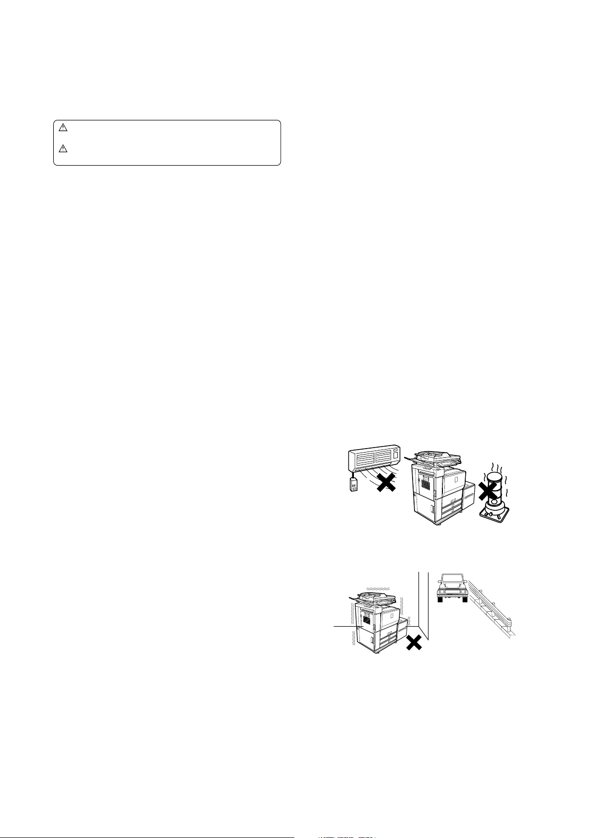
3. Installing site recommendations
Do not install the machine at the following sites.
1) Place of high temperature, high humidity, low tempera-
ture, low humidity, place under an extreme change in temperature and humidity.
Paper may get damp and form dews inside the machine, causing paper jam or copy dirt.
For operating and storing conditions, refer to the specifications
described later.
2) Places of too much vibrations
It may cause a breakdown.
2. Warning for servicing
1) Be sure to connect the power cord only to a power outlet that
meets the specified voltage and current requirements.
Avoid complex wiring, which may lead to a fire or an electric
shock.
It may cause a fire or an electric shock.
2) If there is any abnormality such as a smoke or an abnormal
smell, interrupt the job and disconnect the power plug.
It may cause a fire or an electric shock.
3) Be sure to connect the grounding wire. If an electric leakage
occurs without grounding, a fire or an electric shock may
result.
To protect the machine and the power unit from lightening,
grounding must be made.
MX-M700N NOTE FOR SERVICING - i
Page 5
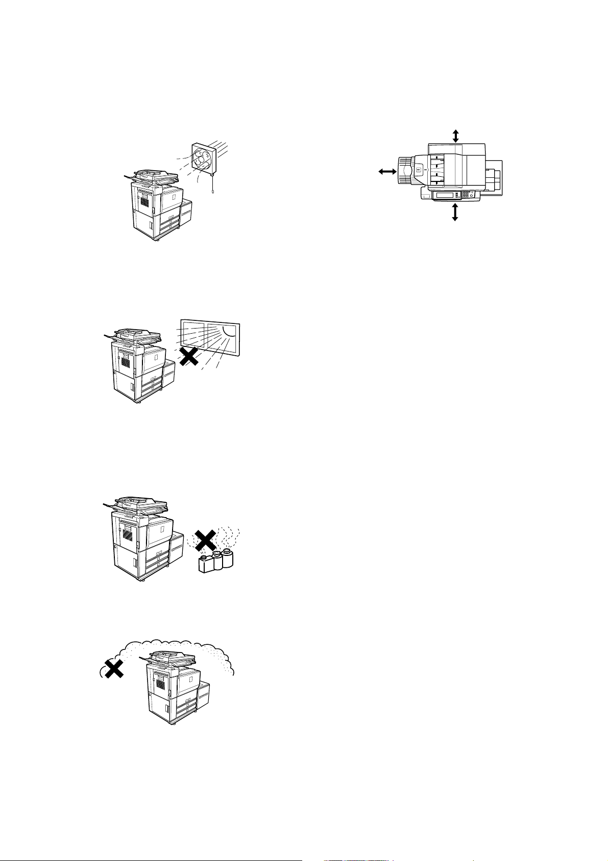
3) Poorly ventilated areas
An electro-static type copier will produce ozone inside it.
The quantity of ozone produced is designed to a low level so
as not to affect human bodies. However, continuous use of
such a machine may produce a smell of ozone. Install the
machine in a well ventilated place, and ventilate occasionally.
4) Place of direct sunlight.
Plastic parts and ink may be deformed, discolored, or may
undergo qualitative change.
It may cause a breakdown or copy dirt.
7) Place too close to a wall
All machines require clean intake and exhaust of air. If the
intake and exhaust of air are not proper, failure of the machine
will occur.
11-13/16"
(30cm)
6-1/8"
(15cm)
23-5/8"
(60cm)
8) Unstable or uneven surfaces
Placement of the machine will affect performance.
An unstable machine may fall over and cause an injury.
Use the proper optional desk unit. When using the optional
desk, be sure to lock the adjusters and casters.
5) Place which is full of organic gases such as ammonium
The organic photoconductor (OPC) drum used in the machine
may undergo qualitative change due to organic gases such as
ammonium.
Installation of this machine near a diazo-type copier may result
in dirt copy.
6) Place of too much dust
When dust enters the machine, it may affect the operation of
the machine.
MX-M700N NOTE FOR SERVICING - ii
Page 6
MX-M700N
[1] PRODUCT OUTLINE
1. Different points of MX-M550/620/700
series from AR-M550/620/700 series
• Adopted new operation panel with 8.9 inch LCD
• Added web roller and motor for web roller in Fusing section
• Added firmware version-up using USB device by Sim 49-1
• Eliminated parallel port
2. Main Features
A. Single Pass Duplex Scanner
• Max. 76 cpm for duplex scanning
• Best-in-class 150-sheet feeder
B. Security Solution
Data encryption + data clear with random number
• Network security
C. New Toner
• Higher density/Finer particles
D. Inner Output
• Separate copy output pages from printer output pages
E. Enhance the solutions such as document
filing and other features.
F. Design for High Reliability
• Robust frame designed by highly accurate CAE analysis
G. Improved Performance
• Network Tandem Copy/Print
• High-speed Processor
• New high-speed ASIC
H. Fax feature
For replacement of mid/low speed devices (up to area)
I. Large Capacity Finisher
Finisher capacity: 4,000-sheet
(2) Strengthened Frame Structure
5GTXKEG/CPWCN
Highly Rigid Frame
Improved stability with less machine distortion, and both rigidity and
lightweight been achieved.
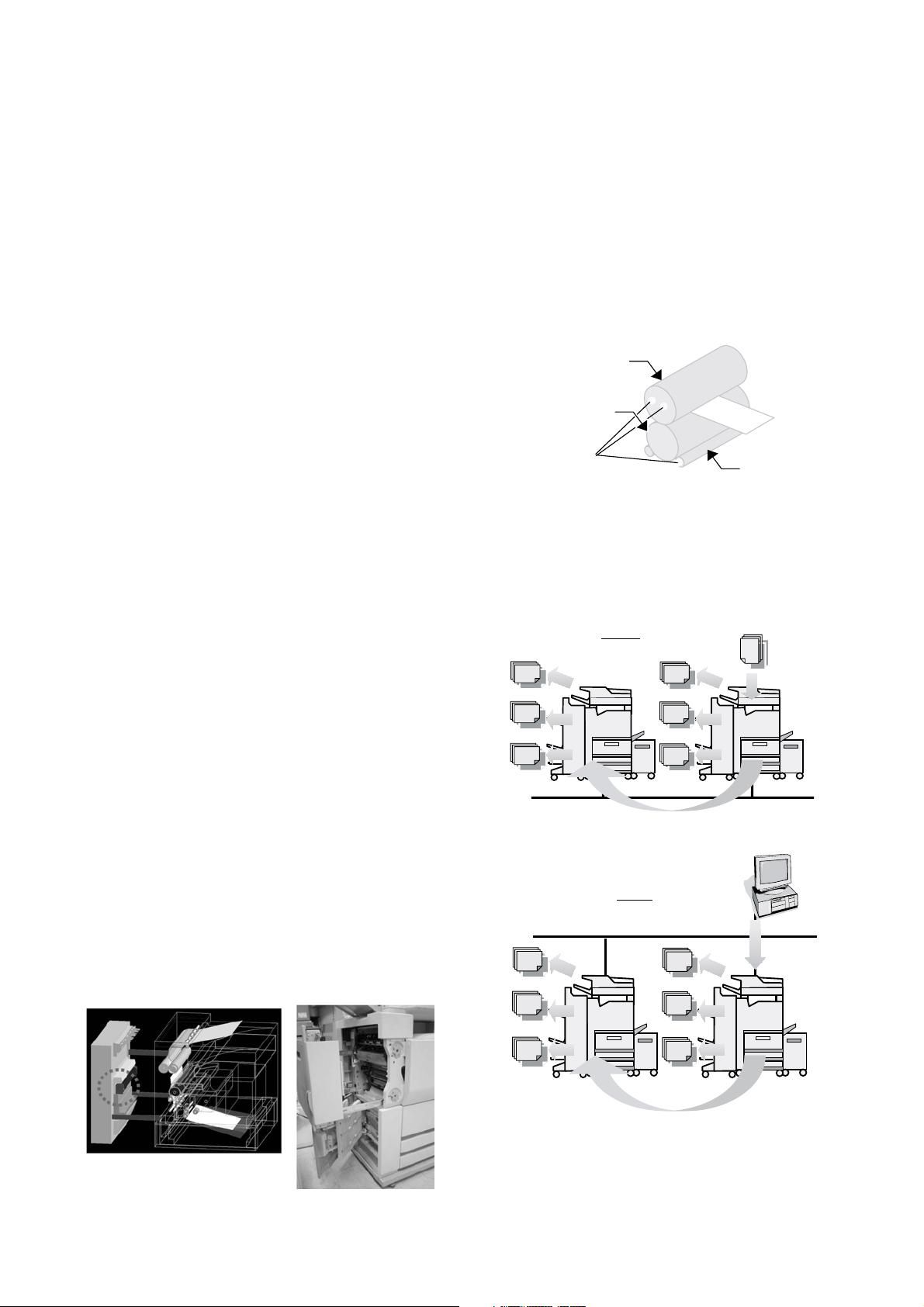
(3) Energy Saving with Unique External Heat Roller
Fusing System
Newly Developed External Heating System
1) High reliability with stabilized fusing ability
2) Shortened warm up time before start copying
3) Achievement of energy efficiency that clears 2006 Rationalization in Energy Use Law
External Heat Roller Fusing System
Thin Steel Fusing
Roller
Low Heat Capacity
Rubber Roller
High Efficiency Heater
External Heating
Roller
B. Network tandem
With Network tandem function, users can output one job on two
network connected engines. Productivity of large-volume copying/
printing can be dramatically improved by high-speed output of up to
110cpm (55cpm model), 124cpm (62cpm model) and 140cpm
(70cpm model).
Scan original from
Copy
document glass or DSPF
3. Features
A. High reliability
(1) Improved Image Quality/Paper Transport
Full-Grip Path Design
Stable paper feeding realized by rollers that firmly grip paper
Small-Diameter Belt Transfer System
With reduced effect to paper types, drum paper release is stabilized
and transfer efficiency is improved
Easier Paper Jam Fixation with Open Paper Path
Jammed paper on vertical paper path can be easily removed by
opening the left side cover, which shortens time to fix paper jam
MX-M700N PRODUCT OUTLINE 1 – 1
Send print
data from PC
Print
* Users can use the function simply by connecting the engines to
network. This means no Tandem Kit (Connection cable) necessary.
Page 7
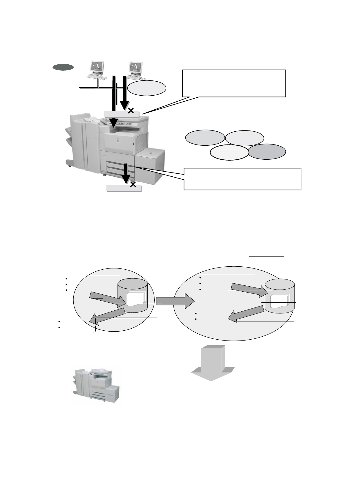
C. 2-Way Security Solution
Document Filing/Quick File
Original data
Print data
Fax data
Install DSK
PIN printing
Password input
Store
Recall (Job settings)
Raw/compressed data
HDD memory
aEncrypted data
Encrypt before storing
Recall (Job settings)
Document Filing/Quick File
Original data
Print data
Fax data
PIN printing
Password input
a
a
HDD memory
ONLY-ONE
Print data
Way-in : Network Security
Allow access of authorized network address only
and prevent unauthorized access from outside.
(Filtering of network address)
(1) Data Security coexisting with Document Filing
Document Filing/Quick File
Original data
Print data
Fax data
PIN printing
Password input
Store
Store
Recall (Job settings)
HDD memory
Raw/compressed dataRaw/compressed data
Install DSK
Copy data
Way-out : HDD Data Clear + Encryption
Data clear by plural writing random number.
Cannot be analyzed even when peeped by encryption.
Print data
Scan data
Fax data
Data SecurityData Security
Document Filing/Quick File
Original data
Print data
Fax data
PIN printing
Password input
Encrypt before storingEncrypt before storing
Recall (Job settings)
HDD memory
Encrypted dat
Encrypted dat
Encrypted dat
Security is assured by encrypting the data to be stored!
Security is assured by encrypting the data to be stored!
MX-M700N PRODUCT OUTLINE 1 – 2
Page 8
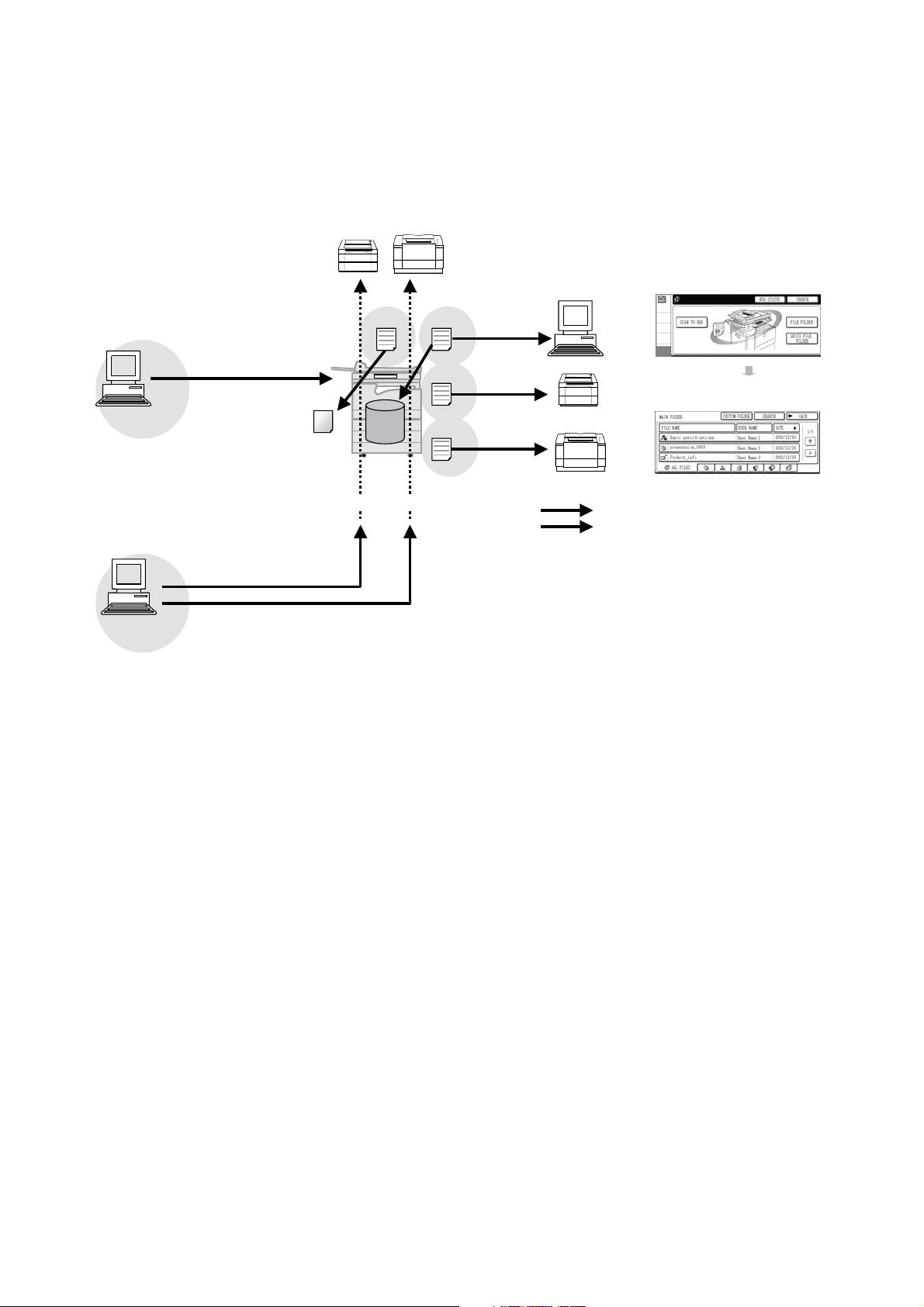
D. Document Filing
>
MX-M550N/U
MX-M620N/U
MX-M620N/U
Document filing is a function that enables users to share and reuse
data stored in the engine's HDD by digitalizing various information
sent/scanned from printer, fax, PC or MFP that are connected by
network.
Print
PC
PC Fax
PC i-Fax
Print data
PC-Fax is like printing
Word data etc. onto fax
paper.
G3 Fax
Fax data
Copy
HDD
MX-M550N/U
MX-M620N/U
MX-M700N/U
i-Fax data
Internet-Fax
Scan
FAX
i-FAX
Telephone line
Network/LAN
Send E-mail
Send
Send E-mail
<Document Filing initial screen>
PC
<List of data stored in Main folder
G3 Fax
Internet Fax
MX-M700N PRODUCT OUTLINE 1 – 3
Page 9
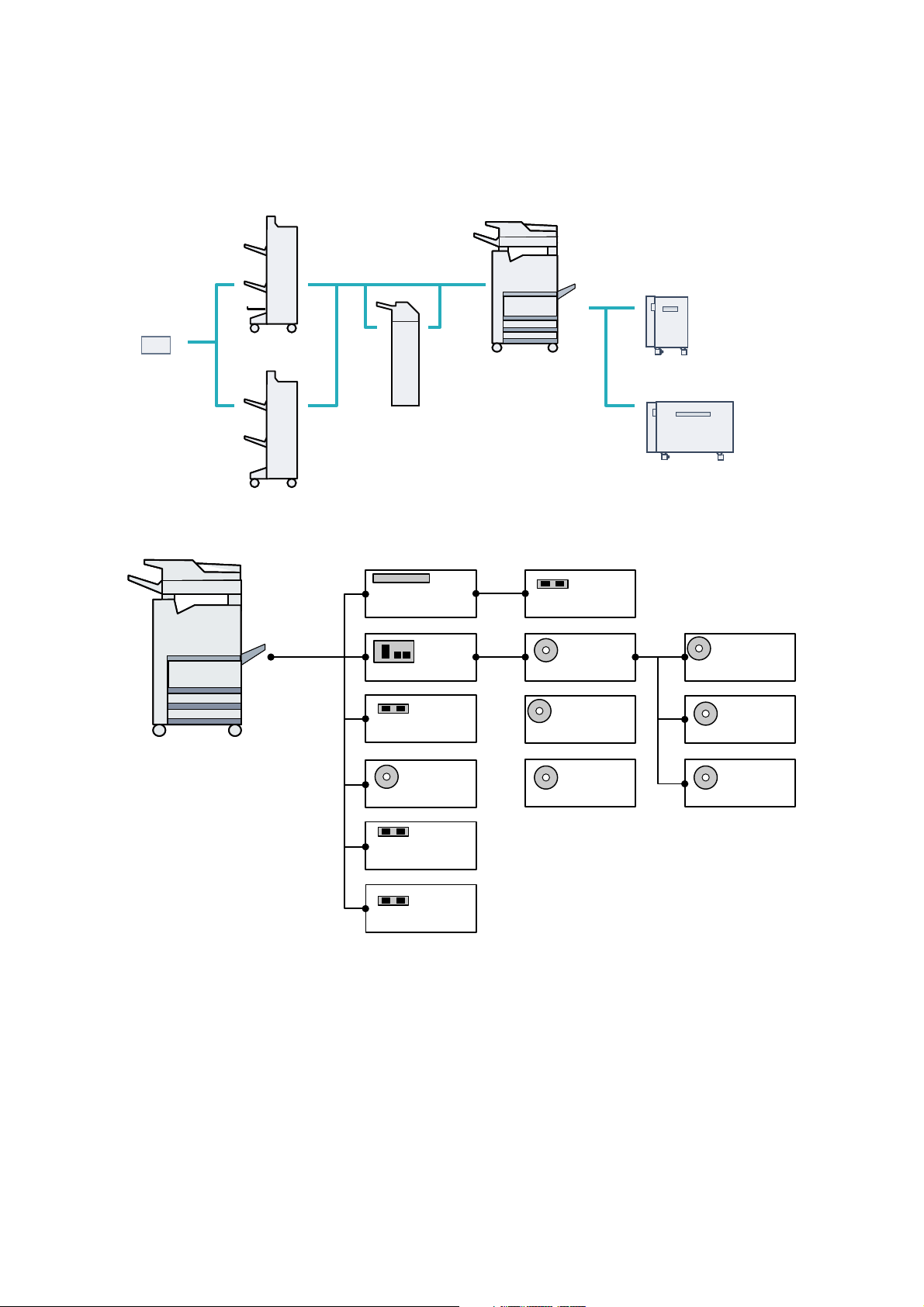
4. CONFIGURATION
A. Main unit and option lineup
(1) Option lineup
Saddle stitch finisher
Punch unit
Finisher
Inserter
55/62/70ppm
A4 LCC
A3 LCC
55/62/70ppm
Printer function
Standard
Facsimile
expansion kit
Network
expansion
kit
Barcode font kit
PS3 expansion kit
256MB expansion
memory board
Data security kit
FAX momory (8MB)
Network
scanner
expansion kit
Application
communication
module
External
account
module
SHARPDESK
1 (5, 10, 50, 100)
license kit
Application
integration
module kit
Internet FAX
expansion kit
MX-M700N PRODUCT OUTLINE 1 – 4
Page 10
(2) Option combinations
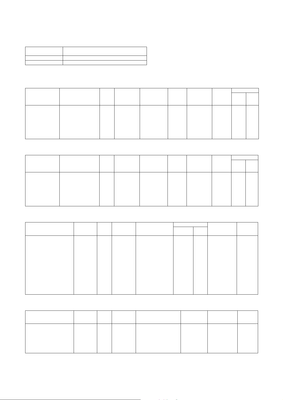
STD: Standard provision OPT: Installable u : Not installable
Option Machine model
Section
Item
Copier model Network printer
MX-M550U/
M620U/M700U
MX-M550N/
M620N/M700N
Paper feed system Large capacity tray (AR-LC6) OPT OPT (A4 / 8.5
Large capacity tray (AR-LC7) OPT OPT (A3 / 11
Remarks
u 11 )
u 17)
Product
Paper exit system Finisher (AR-F15) OPT OPT
Saddle stitch finisher (AR-F16) OPT OPT
Inserter (AR-CF2) OPT OPT
Punch module (AR-PN4A) OPT OPT (2 holes)
Punch module (AR-PN4B) OPT OPT (3 holes)
Punch module (AR-PN4C) OPT OPT (4 holes)
Punch module (AR-PN4D) OPT OPT (4 holes, wide)
Electrical system
(Printer controller)
Printer expansion kit STD STD
Network expantion kit (MX-NBX1) OPT STD Yes
Expansion memory (AR-SM5) OPT OPT (256MB)
PS3 expansion kit (MX-PKX1) OPT OPT Yes
Barcode font kit (AR-PF1) OPT OPT
Software Network scanner expansion kit (MX-NSX1) OPT OPT Yes
Sharpdesk 1 license kit (MX-USX1) OPT OPT
Sharpdesk 5 license kit (MX-USX5) OPT OPT
Sharpdesk 10 license kit (MX-US10) OPT OPT
Sharpdesk 50 license kit (MX-UX50) OPT OPT
Sharpdesk 100 license kit (MX-USA0) OPT OPT
FAX system Internet FAX expansion kit (MX-FWX1) OPT OPT Yes
Facsimile expansion kit (AR-FX8) OPT OPT
FAX expansion memory (8MB) (AR-MM9) OPT OPT
Other options Application integration module kit (MX-AMX1) OPT OPT Yes
Application communication module (MX-AMX2) OPT OPT Yes
External account module (MX-AMX3) OPT OPT Yes
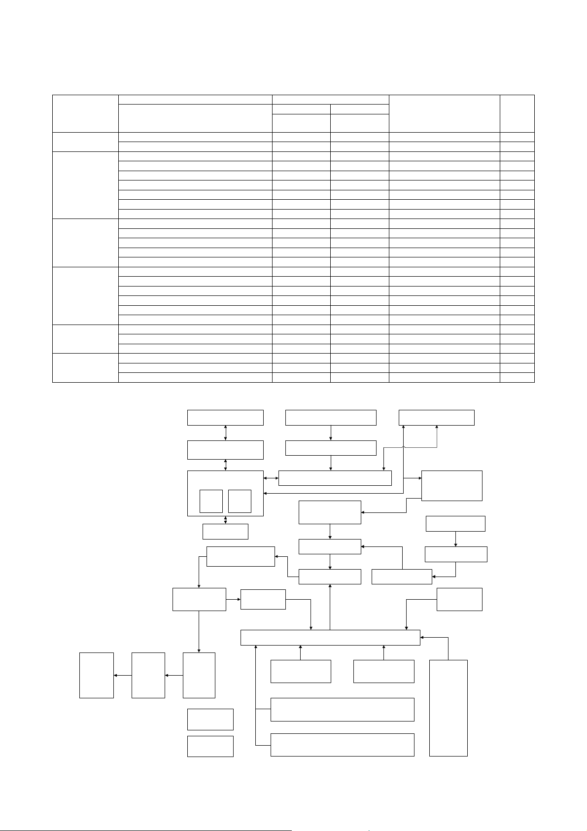
B. Block diagram
key
Finisher
(Option)
Punch Unit
(Option)
Telephone Line
Fax unit (Option)
MFP Control PWB
USB
Port
Paper Exit and switch
back Section
Inserter
(Option)
Network
Port
HDD
Fusing Section
ADU Section
DSPF Unit (CIS)
Image Scanner (reading) Section (CCD)
Scanner Control PWB
Scanner(writing)
(LSU) Section
Drum Section
Developer SectionTransfer Section
Paper Transpor t Section
Paper Feed Tray 1 Paper Feed Tray 2
Operating Section
Engine Control Section
(PCU PWB)
Toner Bottle
Toner Hopper
Manual Paper
Feed Tray
DC Power Unit
AC Power Unit
Paper Feed Tray 3
Paper Feed Tray 4
MX-M700N PRODUCT OUTLINE 1 – 5
Large Capacity
Paper Tray Unit
(Option)
Page 11
MX-M700N
[2] SPECIFICATIONS
1. Basic specifications
A. Base engine
(1) Type
Type Console
Copy mode Monochrome digital
(2) Engine speed (ppm)
Paper size 55ppm 62ppm 70ppm
A4, 8.5 ✕ 11 55ppm 62ppm 70ppm
A4R, 8.5 ✕ 11R 40ppm 45ppm 48ppm
A5R/5.5 ✕ 8.5R
5.5 ✕ 8.5-R
B5 55ppm 62ppm 70ppm
B5R, 7.25 ✕ 10.5-R 40ppm 45ppm 48ppm
B4/8.5 ✕ 14 35ppm 39ppm 45ppm
A3/11 ✕ 17 30ppm 34ppm 39ppm
Extra 30ppm 34ppm 39ppm
Postcard Since the next paper is fed after completion
(3) Engine composition
Photoconductor kind OPC (Drum diameter: I80mm)
Copying method Electronic photo (Laser)
Developing system Dry, 2-component magnetic brush
Charging system Charged saw-tooth method
Transfer system Static electricity transfer
Cleaning system Counter blade
Fusing system Heat roller
Fused cleaning system WEB cleaning method
Toner supply method Toner supply by the front cover open
Waste toner disposal Toner cartridge collection
(4) Engine resolution
Resolution (Writing) Copy : 600 ✕ 600dpi
Smoothing Copy: None
Gradation [Writing] 2 gradations
(5) Warmup
After turned on 120 seconds or less
Pre-heat YES
(6) Jam recovery time
Jam recovery time Approx. 30 sec. (After leaving the machine
(7) Printable area
(Electronic photo graphic)
40ppm 45ppm 48ppm
of paper exit outside the machine, it
depends on the machine composition.
development
(Transfer belt method)
(No toner recycling system)
Printer:
PCL: 600 ✕ 600dpi, 300 ✕ 300dpi
PS : 600 ✕ 600dpi
Printer:
Model of 55/62 sheets:
Equivalent to1200dpi ✕ 600dpi (PCL/PS)
Model of 70 sheets : None
with the side cover open for 60sec, in the
standard condition and the polygon stop
conditions.)
5GTXKEG/CPWCN
(8) Image defect
a. Void area/Image loss
Void area/Image
loss
(9) Power source
Voltage 100 to 127V 200 to 240V
Current 55 ppm 16A 8A
62 ppm 16A 8A
70 ppm 16A 8A
Frequency 50/60Hz
Power source code Dedicated outlet
Power switch 2 switches (Primary switch: in the front cover;
(10) Power consumption
Low power consumption
mode
Maximum rated power
consumption
Reset time from low power
mode
Power consumption in the
off mode
Shift time to off mode 90 min.
* : With full options
(11) Dimensions
Outer dimensions 728 ✕ 679 ✕ 1050mm
Footprint 728 (W) ✕ 679 (D) mm
(12) Weight
Main unit Approx. 185kg / 408lbs
(13) Dimensions occupied by Machine
Main unit 1264 ✕ 679 ✕ 119 2 mm
Main unit + A4-LCC installed 1340 ✕ 679 ✕ 119 2m m
Main unit + finisher/
Saddle finisher installed
Main unit + A4-LCC + finisher/
Saddle finisher installed
Main unit + Inserter + Finisher/
Saddle finisher
Main unit + A4-LCC + Inserter +
Finisher/Saddle finisher installed
Main unit + A3-LCC installed 1660 ✕ 679 ✕ 119 2m m
Main unit + A3-LCC + finisher/
Saddle finisher installed
Main unit + A3-LCC + inserter +
finisher/ Saddle finisher installed
Lead edge: 40mm or less
Rear edge: 4.0mm or less
FR total : 8.0mm or less
100V series 200V series
Seconday switch: on side of the main unit)
100V series 200V series
55 ppm : max. 261.75W
6 2 p p m : ma x . 2 88 . 7 W
7 0 p p m : m a x . 3 1 9 . 5 W
1.80KW (*) 1.84KW (*)
30 sec.
95W or less
(Height: Floor to Glass surface)
728 ✕ 679 ✕ 1192m m
(Height: Floor to SPF top)
1797 ✕ 679 ✕ 1192 mm
1873 ✕ 679 ✕ 1192 mm
2079 ✕ 679 ✕ 1192 mm
2155 ✕ 679 ✕ 1192 mm
2193 ✕ 679 ✕ 1192 mm
2475 ✕ 679 ✕ 1192 mm
A3 289 ✕ 412mm 11 ✕ 17 271 ✕ 424mm
B4 242 ✕ 356mm 8.5 ✕ 14 208 ✕ 348mm
A4 202 ✕ 289mm 8.5 ✕ 13 208 ✕ 322mm
B5 174 ✕ 249mm 8.5 ✕ 11 208 ✕ 271mm
A5 140 ✕ 202mm 5.5 ✕ 8.5 132 ✕ 208mm
7.25
✕ 10.5 183 ✕ 259mm 8K 262 ✕ 382mm
Postcard 92 ✕ 140mm 16K 187 ✕ 262mm
MX-M700N SPECIFICATIONS 2 – 1
Page 12
B. Paper feed, paper transport, and paper exit section
(1) [Paper feed section]
Type 4-stage paper feed tray
(Parallel LCC + 2 tray + Multi manual paper feed)
Paper feed method Paper is fed from the above by the front loading system.
Dehumidification heater Service parts
(2) Paper feed tray of the main unit
a. Tray1 (Left tray in the parallel LCC)
Allowable
paper type and
weight for
paper feed
Plain paper:
60 to 105g/m
(16 to 28lbs)
Allowable
paper type and
weight for
paper feed
Plain paper:
60 to 105g/m
(16 to 28lbs)
Paper size
AB (Europe, SCA):
A4, 8.5 ✕ 11
Paper size change
method
Paper
type
setting
Size setting by user YES Inch: 8.5 ✕ 11
Paper size
setting when
shipping
AB: A4
AB (Other):
A4, 8.5 ✕ 11
Inch: 8.5 ✕ 11, A4
(Supported by the
guide change and
the software setting)
* Time required from tray insertion to empty detection when paper is empty.
b. Tray2 (Right tray in the parallel LCC)
Paper size
AB (Europe, SCA):
A4, 8.5 ✕ 11
AB (Other):
A4, B5, 8.5 ✕ 11
Inch: 8.5 ✕ 11, A4
(Supported by the
guide change and
the software setting)
Paper size change
method
A4: User can change
8.5 ✕ 11:
User can change
B5:
Size setting by
serviceman (B5 available
through bolt fixing and
setting by serviceman)
Paper
type
setting
YES Inch: 8.5 ✕ 11
Paper size
setting when
shipping
AB: A4
(16K is not
supported)
* : Time required from tray insertion to empty detection when paper is empty.
c. Tray3 (multi-purpose tray)
2
2
Paper
capacity
(Standard
paper)
800
sheets
2
(80g/m
Paper
capacity
(Standard
paper)
1200
sheets
(80g/m2)
Paper type
Normal paper,
printed paper,
recycled
)
paper,
letterhead,
punched
paper, color
paper
Paper type
Normal paper,
printed paper,
recycled
paper,
letterhead,
punched
paper, color
paper
Paper
remaining
detection
Enable
(Paper
empty and
3 steps)
Paper
remaining
detection
Enable
(Paper
empty and
3 steps)
Tray lift ti me
Up Down
Within
12sec
(*)
Tray lift time
Up Down
Within
12sec
(*)
Free
fall
Free
fall
Paper size
Auto AB: A3, B4, A4, A4R, B5,
B5R, A5R, 8.5 ✕ 13
Auto inch: 11 ✕ 17, 8.5 ✕ 14,
8.5 ✕ 11, 8.5 ✕ 11R,
Paper size
change
method
Guide
adjustment
by user
Paper
type
setting
Paper size
setting when
shipping
YES Shipped with
the paper
guide width at
Max.
7.25 ✕ 10.5R, 5.5 ✕ 8.5R
Manual: 8K, 16K, 16KR
Special size
:[Vertical]
139 to 297mm (5.5 to 11-5/8)
[Horizontal]
139 to 431mm (5.5 to 17)
(Tab paper is of A4; limited to
tab width 12mm to 20mm/8.5 ✕
11; tab width 6.1mm to 17mm.)
2
* 105g/m
or above, A4/8.5 ✕ 11 or less. For 128g/m2 or above, horizontal feed only.
d. Tray 4 (500 sheets paper feed tray)
Paper size
Auto AB: A3, B4, A4, A4R, B5,
B5R, 8.5 ✕ 13
Auto inch: 11 ✕ 17, 8.5 ✕ 14,
8.5 ✕ 11, 8.5 ✕ 11R,
7.25 ✕ 10.5R
Manual: 8K, 16K, 16KR
Custom size: None
2
* 1: 105g/m
or above, A4/8.5 ✕ 11 or less. For 128g/m2 or above, horizontal feed only.
Paper size
change
method
Guide
adjustment
by user
Paper
type
setting
Paper size
setting when
shipping
YES Shipped with
the paper
guide width at
Max.
* 2: For multi copy and back surface copy, single feed only.
Allowable paper type
and weight for paper
feed
Plain paper:
60 to 105g/m
2
(16 to 28lbs)
Thick paper:
106 to 128g/m
(29 to 34lbs)
176g/m
Cover
205g/m
2
(65lbs)
2
2
(110lbs) Index(*)
Allowable paper type and
weight for paper feed
Plain paper:
60 to 105g/m
Thick paper:
106 to 128g/m
176g/m
205g/m
2
(16 to 28lbs)
2
(29 to 34lbs)
2
(65lbs) Cover
2
(110lbs)Index
(*1),(*2)
Paper capacity
Normal
paper
500 sheets
2
(80g/m
)
Paper capacity
(Standard
paper)
500 sheets
(80g/m
2
)
OHP
40
sheets
Paper type
Normal paper,
printed paper,
recycled paper,
letterhead,
punched paper,
color paper,
label paper,
thick paper, OHP,
tab paper
Paper type
Normal paper,
recycled paper,
printed paper,
letterhead,
punched paper,
color paper,
thick paper
Paper
remaining
detection
Enable
(Paper
empty and
3 steps)
Paper
empty
detection
Enable
(Paper
empty and
3 steps)
MX-M700N SPECIFICATIONS 2 – 2
Page 13
(3) Bypass tray
Paper size
Auto AB: A3, B4, A4, A4R, B5,
B5R, A5R, 8.5 ✕ 13, Postcard
Auto inch: 11 ✕ 17, 8.5 ✕ 14,
8.5 ✕ 13, 8.5 ✕ 11, 8.5 ✕ 11R ,
7.25 ✕ 10.5R, 5.5 ✕ 8.5R
Manual: 8K, 16K, 16KR
Custom size:
[Vertical]
100 to 297mm (3.9 to 11-5/8)
Paper size
change
method
Guide
adjustment by
user
Paper
Allowable paper type and weight
type
setting
YES Thin paper:
52 to 59g/m
(single feed only)
Plain paper:
60 to 105g/m
Thick paper:
106 to 128g/m
176g/m
205g/m
for paper feed
2
(14 to 15lbs)
2
(16 to 28lbs)
2
(29 to 34lbs)
2
(65 - lbs) Cover
2
(110lbs) Index (*)
Paper capacity
(Standard paper)
Plain paper:
100 sheets
(standard paper:
2
80g/m
)
Postcard: 20 sheets
OHP: 20 sheets
[Horizontal]
139 to 432mm (5.5 to 17)
* 105g/m2 or above, A4/8.5 ✕ 11 or less. For 128g/m2 or above, horizontal feed only.
(4) Duplex (5) Paper exit size / type
System Non stack system
Paper size A3, B4, A4, A4R, B5, B5R, A5R, 8K, 16K,
16KR, 11 ✕ 17, 8.5 ✕ 14, 8.5 ✕ 13.4, 8.5 ✕ 13,
8.5 ✕ 11, 8. 5 ✕ 11R , 8 .5 ✕ 5.5R, 7.25 ✕ 10.5R
Type and weight of
paper which can be
passed
Plain paper: 60 to 105g/m
Thick paper: 106 to 128g/m
176g/m
205g/m
2
(16 to 28lbs)
2
(29 to 34lbs)
2
(65 - lbs) Cover
2
(110lbs) Index
Paper type Plain paper, printed paper, recycled paper,
letterhead, punched paper, color paper, thick
paper
Paper exit position/
Main unit top surface face-down paper exit
system
Paper exit capacity 250 sheets (80g/m
Paper exit paper size/kind All kinds of paper which can be fed
Remaining paper
None
detection
Paper exit paper full
Provided
detection
C. Scanner section
(1) Resolution/Gradation
Paper type
Normal paper,
recycled paper,
printed paper,
punched paper,
color paper,
letterhead, thin
paper, label paper,
thick paper, OHP,
tab paper (tab width
20mm or less),
Postcard
2
paper)
Paper
empty
detection
YES
copy mode
Platen Magnification ratio 25 to 99 Normal ratio 101 to 171 172 to 400
Scan resolution (dpi) 600 ✕ 600 600 ✕ 600 600 ✕ 600 600 ✕ (600 ✕ 2)
DSPF Magnification ratio 25 to 99 Normal ratio 101 to 117 118 to 200
Scan
resolution
(dpi)
When in single copy 600 ✕ 367 600 ✕ 367 600 ✕ 367 600 ✕ 600
SPF duplex (front) CCD 600 ✕ 600 600 ✕ 600
600x
(600 ✕ 2)
SPF duplex (back) CIS 600 ✕ 300 600 ✕ 300 600 ✕ 600 600 ✕ 600
When in the Fax send mode and the scanner FAX broadcast mode
Select mode Standard Fine text Super fine test Ultra fine text 600dpi send (*)
Input and send
resolution (dpi)
Input resolution: OC 600 ✕ 600 600 ✕ 600 600 ✕ 600 600 ✕ 600
Input resolution: DSPF simplex 600 ✕ 367 600 ✕ 367 600 ✕ 367 600 ✕ 367
Input resolution: DSPF duplex (front) CCD 600 ✕ 600 600 ✕ 600 600 ✕ 600 600 ✕ 600
Input resolution: DSPF duplex (back) CIS 600 ✕ 300 600 ✕ 300 600 ✕ 300 600 ✕ 300
Transmission
resolution
FAX 20 3.2 ✕ 97.8 203.2 ✕ 195.6 203.2 ✕ 391 406.4 ✕ 391 —
Internet FAX 200 ✕ 100 200
✕ 200 200 ✕ 400 400 ✕ 400 600 ✕ 600
Scanner mode
Select mode 200 ✕ 200 300 ✕ 300 400 ✕ 400 600 ✕ 600
Input and send
resolution (dpi)
Input resolution: OC 600 ✕ 600 600 ✕ 600 600 ✕ 600 600 ✕ 600
Input resolution: DSPF simplex 600 ✕ 367 600 ✕ 367 600 ✕ 367 600 ✕ 367
Input resolution: DSPF duplex (front) CCD 600 ✕ 600 600 ✕ 600 600 ✕ 600 600 ✕ 600
Input resolution: DSPF duplex (back) CIS 600 ✕ 300 600 ✕ 300 600 ✕ 300 600 ✕ 300
Transmission resolution 200 ✕ 200 300 ✕ 300 400 ✕ 400 600 ✕ 600
Exposure lamp None-electrode xenon lamp (Front), LED (Back)
Scanning 256 gradations (8bit)
Printing 2 gradations (1bit)
* Except for FAX sending
600x
(600 ✕ 2)
MX-M700N SPECIFICATIONS 2 – 3
Page 14
(2) Document table
2. Functional specifications
Scanning area 297 ✕ 431.8mm
Original
standard
position
Detection Provided
detection size Automatic detection
Manual
detection size
setting
Dehumidificati
on heater
(Scanner
section)
Left bottom reference
(Supported by changeover of the software destination of
one kind of the detection unit.)
Inch series-1 11 ✕ 17, 8.5 ✕ 14, 8.5 ✕ 11, 8. 5 ✕ 11R ,
5.5 ✕ 8.5
Inch series-2 11 ✕ 17, 8.5 ✕ 13, 8.5 ✕ 11, 8. 5 ✕ 11R ,
5.5 ✕ 8.5
AB series-1 A3, B4, A4, A4R, B5, B5R, A5
AB series-2 A3, A4, A4R, B5, B5R, A5, 216 ✕ 330
AB series-3 B4, A4, A4R, A5, 8K, 16K, 16KR
Manual setting fixed size input:
Min. : 64 ✕ 64 to Max.297 ✕ 432mm
Provided
Service parts
(3) Automatic document feeder
Type DSPF: Duplex surface scan and feed unit
Scan speed When in single copy When in duplex copy
Original standard
position
Document size Automatic detection
Document weight 50 to 128g/m
Max. loading
capacity of
documents
Copy 65 sheets/min
Scanner 59 sheets/min
Internet
(600 ✕ 300 dpi, 1bit)
Fax 46 sheets/min
FAX
(Normal text, 1bit)
(200 ✕ 200dpi, 1bit)
46 sheets/min
(200 ✕ 100dpi, 1bit)
Center reference
Inch series-1:
11 ✕ 17, 8.5 ✕ 14, 8.5 ✕ 11, 8 .5 ✕ 11 R, 8.5 ✕ 5.5,
A4
Inch series-2 :
11 ✕ 17, 8.5 ✕ 13, 8.5 ✕ 11, 8.5 ✕ 11R, 8 .5 ✕ 5.5,
A4
AB series-1/-2:
A3, B4, A4, A4R, B5, B5R, A5, 8.5 ✕ 11, 8.5 ✕ 13
AB series-3 :
8K, A4, A4R, B4, 16K, 16KR, A5, 8.5 ✕ 13
Mix paper feed (Same series, same width paper)
enabled
Manual setting Min. 64 ✕ 64 to Max.297 ✕ 432mm
(Scan position: Center reference)
2
14 to 34lbs, 65 lbs Cover (Equivalent of 176g/m2),
110 lbs Index (Equivalent of 205g/m
Max. 150 sheets (80g/m
76 pages/min
(600 ✕ 300dpi, 1bit)
48 sheets/min
(Normal text, 1bit)
67 sheets/min
(200 ✕ 200dpi, 1bit)
48 sheets/min
(200 ✕ 100dpi, 1bit)
2
2
) or Max. 19.5mm
)
D. Fuser section
(1) Type
System Heat roller pressure system
A. Copy functions
(1) Copy speed (Continuous copy speed) (cpm)
a. Tray 1 to 4, LCC (Reduction/Normal/Enlargement)
Copy mode Paper size 55ppm 62ppm 70ppm
Original table
mode
(2) First copy time
Original Cover
/DSPF
Original Cover 4.0 seconds or less 3.5 seconds or less
DSPF 6.2 seconds or less 5.7 seconds or less
* Measurement conditions: Feeding A4/8.5 ✕11 paper from the
main unit tray. Polygon in rotation.
(3) Job speed
a. BLI standards
S to S 50.1cpm (91%) 56.4cpm (91%) 63.0cpm (90%)
S to D 49.0cpm (89%) 53.3cpm (86%) 58.8cpm (84%)
D to D 51.7cpm (94%) 57.0cpm (92%) 63.0cpm (90%)
* S to S: A4/8 ✕ 11 documents 10 sheets, copy 5 sets
* S to D: A4/8 ✕ 11 documents 10 sheets, copy 5 sets
* D to D: A4/8 ✕ 11 documents 10 sheets (20 pages), copy 5 sets
(4) Continuous copy
Multi max. quantity 999 sheets
(5) Resolution
Scan resolution 600 ✕ 600dpi
Writing resolution 600 ✕ 600dpi
(6) Copy document
Document size Max. A3
Document type Sheet/Book original
(7) Copy magnification ratio
Copy magnification
ratio
Zoom 25 to 400% (25 to 200% for DSPF)
Preset magnification
ratio
(8) Density, copy image quality processing
Exposure mode Binary: Text (auto/manual), Text/Photo, photo,
Number of manual
steps
Toner save mode Provided
A4, 8.5 ✕ 11 55 62 70
A4R, 8.5 ✕ 11R 404548
A5R/5.5 ✕ 8.5R,
5.5 ✕ 8.5-R
B5 55 62 70
B5R, 7.25 ✕ 10.5-R 40 45 48
B4/8.5 ✕ 14 35 39 45
A3/11 ✕ 17 30 34 39
Extra 303439
Postcard Since the next paper is fed after
55ppm 62ppm 70ppm
55ppm 62ppm 70ppm
AB series: 25%, 50%, 70%, 81%, 86%, 100%,
Inch series: 25%, 50%, 64%, 77%, 100%,
4
auto
9 steps
40 45 48
completion of paper exit outside
the machine, it depends on the
machine composition.
115%, 122%, 141%, 200%, 400%
121%, 129%, 200%, 400%
MX-M700N SPECIFICATIONS 2 – 4
Page 15

(9) Paper size
Paper
type
AB
series
Inch
series 8.5 ✕ 5.5 11 ✕ 17
Standard size
Min. Max.
A6 (A6R)
Postcard
(10) Copy functions
Function
(Special
function)
Automatic paper selection Yes
Automatic magnification
ratio selection
Vertical/horizontal
independent
magnification ratio
Paper type select Yes
Auto tray switching Yes
Rotation copy Yes
Electronic sort Yes
Rotation sort Yes (Europe, SCA, Dealer area)
Job reservation Yes (99 items)
Program call/register Yes (10 items)
Document filing Yes
Preheat function Yes
Auto power shut off
function
User management (Dept.
management)
Process control Yes
Indefinite document size
input
Indefinite paper size input Yes (Tray 3/manual paper feed)
Mixed document feeder Yes (MIX only)
Binding margin Yes (Left/Right)
Border erase/Center
erase
2 in 1 Yes
Tandem copy Yes
Cover/Insert paper/Tab
insert paper
OHP insert paper Yes
Tab copy Yes
2in1/4in1 Yes (Centering provided)
Card shot Yes (Centering provided)
Center binding Yes (Centering provided)
Book copy Yes
Duplex copy system
switch
Large volume document
mode
Black-white reversion Yes (except UK)
Mirror image Yes
Date print Yes
Stam p Yes
Page print Yes
Character print Yes
Standard size
A3, B4, A4, A4R, B5, B5R, A5R,
A3
8K, 16K, 16KR, Postcard
11 ✕ 17, 8.5 ✕ 14, 8.5 ✕ 13,
8.5 ✕ 11, 8.5 ✕ 11 R,
7.25 ✕ 10.5R, 5.5 ✕ 8.5R
(Conditions set up
by system setting)
(Conditions set up
by system setting)
Yes (500 users)
(Border/Center/Border+Center)
(Network interface is required)
Yes (Max. 10000 sheets)
Magnification ratio/ Density/
Paper can be changed for every
bundle.
Yes
Yes
Yes
Yes
Yes
Yes
Yes
B. Image send function
(1) Mode
Scanner Scan to E-mail
Fax Fax
Internet
Fax
* Conforming to PC-FAX/PC-internet fax
(2) Image send function (Push from the main unit)
a. Support system
Corresponding
server/protocol
SMTP, POP3 and FTP support SSL. (Web support)
b. Support image
File format TIFF, PDF TIFF-FX (TIFF-F) —
Compression
system
c. Image process
half tone
reproduction
Density
adjustment
Image quality
selection
Resolution
(depends on
file format/
transmission
method)
Scan to Desktop
(Scan data send without depending on the IP address under
the DHPC environment)
Scan to FTP
Scan to Folder (SMB)
Scan to e-mail with Meta
Scan to Desktop with Meta
Scan to FTP with Meta
Scan to SMB with Meta
Fax to E-mail (inbound Routing)
Fax to FTP/Desktop/SMB/E-mail (Document Admin)
Internet Fax (Supported full mode)
Internet Fax to E-mail (inbound routing)
Internet Fax to FTP/Desktop/SMB/E-mail
(Document Admin) (*)
Item Scanner Internet Fax
Item Scanner Internet Fax Fax
Item Scanner Internet Fax Fax
SMTP
FTP(TCP/IP)
SMB
•Noncompression
•G3
(1-dimensional)
= MH (Modified
Huffman)
•G4
= MMR
(Modified MR)
Equivalent of 256 steps
Auto + 5 steps
Half tone ON/OFF
200 ✕ 200dpi Standard
300 ✕ 300 dpi Super fine
400 ✕ 400 dpi Ultra fine
600 ✕ 600 dpi 600 ✕ 600dpi —
POP server
SMTP server
ESMTP server
MH, MMR MH, MR,
(200 ✕ 100dpi)
(middle tone not
allowed)
Fine
(200 ✕ 200dpi)
(200 ✕ 400dpi)
(400 ✕ 400dpi)
MMR, JBIG
Standard
(203.2
✕ 97.8dpi)
(middle tone
not allowed)
Fine
(203.2
✕ 195.6dpi)
Super fine
(203.2
✕ 391dpi)
Ultra fine
(406.4
✕ 391dpi)
MX-M700N SPECIFICATIONS 2 – 5
Page 16
d. Address specification
Item Scanner Internet Fax Fax
Address
specification
Setting of
default address
Number of Onetouch address
key registration
Inbound Routing
List
Inbound routing
addresses
Sender Number/
Address
Registration
(Inbound
Routing)
Number of
Group (1 key)
address
registtation
Program 8 items
Direct address
input
Chain dial
Resend Call up nearest address which are specified as a single
Shortcut for
address
selection (quick
key)
CC/BCC
sending
Item name Selective/direct entry from the list —
File name Selective/direct entry from the list —
Return mail
address
Sender name Yes (Selective
Transmission
message
(message body)
Mail footer
preset
Specified by one-touch, group, or direct address input.
Input from the soft keyboard (Scanner/Internet FAX)
Input the 10-key (Fax)
Selection from LDAP server
Resend
Quick
No
Max. total 999 items (of which 200 items can be
assigned to FTP, desktop and/or SMB)
50 items
1000 items
500 items
Number of Group (1 key) address registration : Max.
500 items
Input from the soft keyboard Entry by 10-
—
destination
Use the 10-key to call up registered numbers of
addresses.
Yes —
(1 default
—
from the list/direct
entry from the list/
selection from
LDAP server)
address fixed as
sender name)
—
—
key, # key, *
key
Yes (pause
key)
(1 default
address fixed
as sender
name)
No
e. Multiple address specification
Item Scanner Internet Fax Fax
Address
specification
No. of
registration
items of direct
address input *
Broadcast send Yes
Sequential send
request
Specification by one-touch/group/direct address input.
*
Group, interface broadcasting total max: 5,000 items
(Broadcast
send is disabled
for FTP/
Desktop/SMB)
—Yes
Ye s
* Direct address input: 10-key other than one-touch, and soft key-
board input
• When broadcasting including FAX, the resolution is that of FAX.
• When broadcasting of the internet FAX and the scanner, the resolution is that of the internet FAX.
• The compression type when broadcasting depends on the conforming of the system setting.
f. Send function
Item Scanner Internet Fax Fax
Memory transmission —
Onhook — Yes
Quick online send — Yes
Direct transmission — Only in
Automatic reduction
send
Rotation send Yes (Manual) Yes (Auto)
Zoom send Yes (Zooming of standard size to standard size
Recall
mode
Book document send Yes
Long document send Yes (Max.800mm)
File division send Yes —
Send size limit Yes —
Stamp function Yes
No. of registration
items of senders
Address Confirmation
Function (Prevention
of mis-send)
Error — Yes
Busy — — Yes
When the upper
limit value is set,
memory send is
performed.
—
only. (There are combinations that cannot be
rotated.))
The conditions of recall number and time can be
set with the system setting.
Max. 999 items
—
Ye s
Onhook
Ye s
(A3oB4,
A3oA4,
B4oA4
Ye s
(Soft
switch)
g. Receive function
Item Internet Fax Fax
Automatic reception Yes
Manual reception Yes
Memory reception Yes
Fixed size reduction
reception
Specified size zoom
reception
Rotation reception Yes
Division reception Yes (Conditions are set by the system.)
Duplex reception Yes (Conditions are set by the system.)
2 in 1 reception —
Domain/Address
specification receive
enable
Domain/Address
specification receive
disable
Certain rejection
number setting
External telephone
connection remote
Answering telephone
connection
Transfer function when
output is disable
Automatic boot mode Yes
Yes (50 items) —
Yes (50 items) —
—Yes
—
—
Yes
—
(50 items)
Ye s
No
(PAT countermeasure)
Yes
MX-M700N SPECIFICATIONS 2 – 6
Page 17
h. Report/list function
Item Scanner Internet Fax Fax
Communication
record table
Communication
result table
Address/
Telephone
number table
Group table Yes
Sender table Yes (Sender
Program table Yes
Memory box
table
Memory
contents clear
notification
table
Receivable/
rejection
number list
Receivable/
Rejection
address list
Transfer-toemail table list
Transfer-toadministrator
list
Web setting list Yes
NO Yes
registration table)
(May be outputted in case of an error.)
Yes
Yes
Yes (Described on the system
setting list.)
—
—
—Yes
Yes —
Yes
Yes
Yes (FAX
mode only)
i. Other functions
Item Scanner Internet Fax Fax
Time
specification
Poling receive — Yes
Bulletin board
send
Cover function — NO
Sender print — Yes
Page division Yes
Page
connection
Confidential
data (Remote
machine)
Relay
broadcast
indication
Send message NO
Edge erase Yes
Center erase Yes
2 in 1 Yes
Card shot Yes
Send to PC — PC-iFAX PC-FAX
Linearrized
PDF
Corresponds by
Net Scan Tool
Yes
—Yes
NO
—
—
——
Ye s
(F code
system)
Ye s
(F code
system)
j. Record size
Item Internet Fax Fax
Max. record
width
Record size A3 to A5/11 x 17 to 5.5 x 8.5
293mm
k. F code communication
Item Fax
Sub address Yes (Max. 20 digits)
Pass code Yes (Max. 20 digits)
C. Printer function
(1) Platform
• IBM PC/AT compatible machine
•Macintosh
(2) Support OS
OS
Windows 98 Yes Yes Yes No
Me Ye s Ye s Ye s No
NT 4.0 SP5 or later Yes Yes Yes No
2000 Yes Yes Yes No
XP Yes Yes Ye s N o
Server2003 Yes Yes Yes No
Server2003 x64 No No No Yes
XP x64 No No No Yes
Mac 9.0 to 9.2.2 No No Yes No
X 10.1.5 No No Yes No
X 10.2.8 No No Yes No
X 10.3.9 No No Yes No
X 10.4 - X 10.4.7 No No Yes No
Custom
PCL5e/6
SPDL2
(3) Command system
Command system
PCL5e, PCL6 compatible Standard
PS3 compatible Option (PS expansion kit)
(4) Built-in fonts
Bitmap fonts 1 kind of font
PCL5 Latin font 80 PCL Latin fonts (SPDL)
PCL Kanji font Option (2 ACT Fonts)
PS Latin font 136 Type 1 Latin fonts
Bar code font Option
Standard built-in fonts
Auxiliary to the PS expansion kit
• The printing system is provided with one bitmap font compatible
with HP and 80 European outline fonts for PCL.
• In addition to this, when the PS expansion kit is installed, it is provided with 136 European outline fonts for PS and 5 Japanese
outline fonts.
(5) Support print channel
Support print channel NetWare environment PSERVER/RPRINT
USB USB 1.1:
For NetWare environment
PSERVER/RPRINT
LPR UNIX LPR/LPD command-compatible print
IPP Print channel in compliance with IPP1.0
PAP: EtherTalk
(AppleTalk)
FTP Function to print receive data by use of the
NetBEUI Microsoft NetBEUI compatible print channel
Port9100 Supports 9100 TCP port (Raw Port).
WEB Submit Print This channel is used to set and print directly
LPR
IPP
PAP : EtherTalk (AppleTalk)
FTP
FTP Pull Print
NetBEUI
Raw Port (Port 9100)
USB 2.0
HTTP (WEB Submit Print)
POP3 (E-mail To Print)
Windows98/98SE/Me/2000/XP only
USB 2.0:
Windows 2000/XP only
Print channel in PSERVER/PRINT mode to
be used in netware environment
channel
Print channel used in the Macintosh
environment
builtin FTP server.
the files on the network by Web Page.
Custom
PS
PPD GPD
MX-M700N SPECIFICATIONS 2 – 7
Page 18
E-mail To Print This channel is used to print only an
attached file directly when an E-mail with an
attached file is received.
• IPP, and HTTP supports SSL.
(6) Command compatibility
PCL5e compatible PCL5e is aimed to provide compatibility with HP
PCL6 compatible PCL6 is aimed to provide compatibility with HP
PostScript
compatible
LaserJet 4050.
LaserJet 4050.
PostScript is aimed to provide compatibility with
Adobe PostScript.
(7) Environment setting
Setting item Outline
Default setting Basic setting of printing such as the number of
PCL setting PCL symbol setting and font setting
PS setting Setting of print enable/disable in a PS error
copies and printing direction.
(8) Print function
Functions Content PCL6/5e PS (OPTION)
Multiple Pamphlet Two or more center bindings are collected into one. Yes Yes
Barcode font Compatible with JetCAPS BarDIMM emulation.
Network tandem print Two main units are connected in network and printing can be made by the linkage of the two main
Windows Cluster Print Even if one Windows server is down, the mirror server will execute the interrupted print job
PDF/TIFF direct print PDF/TIFF files can be printed without the printer drivers.
E-Mail To Print When an e-mail with an attached file is received, only the attached file is printed directly. Yes Yes
PULL print from front panel The FTP server is checked from the front panel and only the specified file is pull-printed (direct
USB PULL print The FTP server is checked from the front panel and only the specified file is pull-printed (direct
SMB PULL print The file folder on the network is checked from the front panel, and the specified file is pull-printed. No No
FTP PUSH print Data are transferred from the client PC to the MFP server, and direct print is executed. Yes Yes
Print by setting the file on
the Web Page.
[Web Submit Print]
ROPM One RIP process allows to print two or more copies. Yes Yes
Conforming to multi access RIP process can be executed during printing. Printing can be executed during scanning. Yes Yes
Setting of the paper
direction for duplex print of
letterhead paper and
punched paper
Manual specification type/
Size detection enable
setting
Management of setting
environment under the
terminal server control
Driver delivery function The administrator can distribute the driver to each client by PAU4.
Form overlay The form is downloaded to the main unit in advance, and only the data are sent to the main unit,
Conforming to Planet Press Supports the Objectif Lune PlanetPress (which performs mapping between the downloaded form
Management of blind Web
Page by the password
Bonjour for
Macintosh environment
Document control print The pattern is printed on paper.
Missing-prevention
marking
Layout print The layout supported for various print purposes can be made. No No
No-line binding To prevent against bulge at the end when binding pages, center binding is executed for small lot of
Chapter division A white sheet is automatically inserted so that the head page of each chapter comes on the odd
True type font for barcode usable in PCL5e.
unit.
instead of the down server.
(1) Print of an attached file of an e-mail
(2) Print from the FTP server
(3) Print from the setting file on the Web page
print).
print).
A file on the network is set on the Web page, and direct print is executed.
For letterhead and punching sheet which has attribute of front and back, duplex print can be made
in the proper front and back and proper page sequence.
When the set value of the manual tray type on the main unit differs from that on the driver side, the
set value of the printer driver has priority over the set value on the main unit and printing is made. Yes Yes
Under the meta-frame environment (under the auto print create environment), the print setting of
each client is saved. (In order to avoid the trouble of having to set at every login.) Yes
where data are loaded into the form to be printed.
and the variable data in the printer).
In order to block access to the address of a blind Web Page.
The technology developed by Apple for detecting and connecting peripheral devices on the
network automatically
Without setting by the user, the computer, the peripheral devices, and the software can be
dynamically connected in netw ork.
(OS X 10.3 and later)
(When the data security kit is installed)
The paper edge is marked in order to judge paper missing.
pages.
(or even) page.
Yes
(5e only)
Yes Yes
Yes
Yes
(PDF is No)
Yes Yes
No No
Yes Yes
Yes Yes
Yes
Yes
(5e only)
No
Yes Yes
No Yes
No No
No No
No No
No No
(Windows only)
(Windows only)
(Windows only)
(Windows only)
No
Yes
Yes
Yes
Yes
Yes
Yes
MX-M700N SPECIFICATIONS 2 – 8
Page 19
(9) Windows driver function
a. Frequently used functions
Functions PCL5e PCL6 PS PPD (*)
Number of
copies
Print
direction
Duplex print Simplex print, duplex print
Center
binding
Binding
direction
N-up 2/4/6/8/9/16 WindowsNT 4.0: —
N-up
direction
N-up frame
line Yes/No
* For printing, the PS driver bundled in Windows is required.
b. Paper feed system
Functions PCL5e PCL6 PS PPD (*)
Paper size A3/B4/A4/B5/A5/Postcard/Ledger/Legal/Foolscap/Letter/
Paper type Normal paper, letterhead, printed paper, punched paper,
User
definition
type
Paper feed
system
Cover paper/
Back cover
page
Cover paper Yes
Insert paper Yes —
OHP insert
paper
* For printing, the PS driver bundled in Windows is required.
c. Paper exit method
Functions PCL5e PCL6 PS PPD (*)
Paper exit
destination
setting
Staple Finisher
Offset Yes (every time)
* For printing, the PS driver bundled in Windows is required.
1 to 999
Vertical/Horizontal
(Left/Upper/Right binding)
Invoice on Letter, Letter on Ledger,
A5 on A4, A4 on A3, B5 on B4,
Letter on Letter, Ledger on Ledger,
A4 on A4, A3 on A3, B4 on B4
Left/Upper/Right Long side/Short
[2-Up]:
Left to Right / Right to Left
[4, 6, 8, 9, 16-Up]:
Right, and Down /
Down, and Right
Left, and Down /
Down, and Left
Executive/Invoice/8K/16K
recycled paper, color paper, label sheet, thick paper, OHP,
tab pape r
7 types
Auto paper feed, Tray 1/2/3/4/5, manual feed
Yes/No Setting of Duplex/Simplex/
No print —
No/Yes (White paper)
Yes (Printed paper)
• Center tray
• Finisher o Tray 1
• Finisher oTray 2
• Saddle stitch finisher oTra y 1
• Saddle stitch finisher oTra y 2
• Saddle stitch finisher o Saddle stitch tray
• No staple
• 1 position
• 2 positions
Saddle stitch finisher
• No staple
• 1 position
• 2 positions
Simplex print,
duplex print (Long
side/Short side
binding)
Windows2000, XP:
Yes
Other OS: No
side
Windows2000, XP:
2/4/6/9/16 Other
OS: 2/4
Yes
(Always prints
border line)
—
d. Image quality
Function PCL5e PCL6 PS PPD (*)
Resolution 600/300dpi 600dpi
Halftone
Graphic mode
selection
Smoothing 55/62ppm: Yes
Toner save Yes/No
Ultra fine photo 55/62ppm: Yes
Black-white
reversion
Mirror image
Zoom — 25 to 400%
Fit page Yes/No —
Raster
HP-GL2
70ppm : No
70ppm : No
(55ppm/
62ppm)
—
Yes/No
(70ppm)
Raster
vector
—Yes/No
—
Screen Frequency 8.0 to
360.0 in 0.1 steps
Screen angle 0.0 to 360.0 in
0.1 steps
—
Horizontal
/Vertical
—
Horizontal
* For printing, the PS driver bundled in Windows is required.
e. Font
Function PCL5e PCL6 PS PPD (*)
Usable built-in
fonts
Download system
which can be
selected
80 fonts
Category 3 and 4
In font chapter
Bitmap, TrueType,
Graphics
136 fonts
Category
1In font
chapter
5 Japanese fonts
Category
2 In font
chapter
Bit map, Ty pe 1, Tr ueType
(For Windows
NT4.0)
Traditional 35
Latin fonts
Category 1 In
font chapter
(For Other OS)
136 Latin fonts
Category 1 In
font chapter 5
Japanese fonts
Category 2 In
font chapter
f. Other functions
Function PCL5e PCL6 PS PPD (*)
Units composition
setting
Waterm ark
Overlay Yes —
Print hold Yes —
Job retention Yes —
Sample print Yes —
Print department
management
User setting Yes —
Option auto setting Yes —
Job complete
notification
Tandem print Yes
Carbon print Yes —
Enlargement
continuous copy
Vertical/horizontal
independent
magnification ratio
Cover insertion
+center binding
Document filing Yes —
—Yes—
Yes
Yes
Yes —
Yes —
—
Yes —
(Limitations on
functions)
Yes
* For printing, the PS driver bundled in Windows is required.
MX-M700N SPECIFICATIONS 2 – 9
Page 20
(10) Windows PPD, Macintosh PPD driver funciton
a. Frequently used functions
Functions Macintosh PPD
Number of copies 1 to 999
Print direction Vertical/Horizontal
Duplex print Simplex print, duplex print (Left/Upper binding)
Center binding Yes
Binding direction Long side/Short side
N-up 2/4/6/8/16
N-up direction Z / Reverse Z/N / Reverse N
N-up frame line None / Single Hairline / Single Thinline / Double
b. Paper feed system
Functions Macintosh PPD
Paper size A3, B4, A4, B5, A5, Postcard, Ledger, Legal,
Paper type Normal paper, letterhead, printed paper, punched
User definition type 7 types
Paper feed system Auto paper feed, Tray 1/2/3/4/5, manual feed
Cover paper/Back
cover page
Cover paper Yes
Insert paper NO
OHP insert paper No/Yes (White paper), Yes (Printed paper)
c. Paper exit method
Function Macintosh
Paper exit
destination setting
Staple Finisher
Offset Yes (every time)
d. Image quality
Function Macintosh
Resolution 600dpi
Halftone (55ppm/62ppm) Yes/No
Graphic mode
selection
Smoothing (55ppm/62ppm) : Yes/No
Toner save Yes/No
Ultra fine photo —
Black-white
reversion
Mirror image Horizontal/Vertical
Zoom 25 to 400%
Fit page No
e. Font
Function Macintosh
Usable built-in
fonts
Hairline / Double Thinline
Foolscap, Letter, Executive, Invoice, 8K, 16K
paper, recycled paper, color paper, label sheet, thick
paper, OHP, tab paper
Yes / No
Top tray
Finisher
Tray 1
Tray 2
Saddle stitch finisher
Tray 1
Tray 2
Saddle stitch tray
• No staple
• 1 position
• 2 positions
Saddle stitch finisher
• No staple
• 1 position
• 2 positions
• Saddle stitch
(70ppm) —
—
(70ppm) : —
Yes / No
Traditional 35 PS Latin fonts
Category 1 In font chapter
5 fonts Category 2 In font chapter
Function Macintosh
Download system
which can be
selected
Yes (Mac OS9.x.x - LaserWriter)
f. Other functions
Function Macintosh
Units composition
setting
Waterm ark Yes
Overlay No
Print hold Yes
Job retention Yes (PIN code input enable)
Sample print Yes
Print department
management
User setting —
Option auto setting Yes
Job complete
notification
Tandem print Yes
Carbon print Yes
Enlargement
continuous copy
Vertical/horizontal
independent
magnification ratio
Cover insertion
+center binding
Document filing —
Yes
Yes
—
—
—
—
(11) Print performance
Model
55ppm PCL6 16.2 sec 33.7 sec 10.5 sec
62ppm PCL6 13.8 sec 31.4 sec 12.8 sec
70ppm PCL6 14.6 sec 31.1 sec 11.9 sec
* Measurement conditions
(Windows) (Macintosh)
PC: Pentium III 1GHz 128MB PC: PowerPC G3 700MHz 256MB
OS: Windows XP Professional
Driver setting: Default
Software: Microsoft Office XP
PDL
type
PCL5e 15.4 sec 32.4 sec 13.0 sec
PS 15.8 sec 50.0 sec 13.9 sec
ppd 14.1 sec 37.1 sec 11.6 sec
PCL5e 15.4 sec 31.5 sec 12.7 sec
PS 15.6 sec 49.9 sec 13.9 sec
ppd 13.4 sec 41.3 sec 12.2 sec
PCL5e 15.4 sec 30.5 sec 13.3 sec
PS 14.6 sec 49.2 sec 13.4 sec
ppd 14.3 sec 37.0 sec 11.0 sec
Word:
script.doc (eng.)
A total of
9 pages
Excel:
xl8garly.xls
A total of
20 pages
PowerPoint:
Pw4051.ppt
A total of
6 pages
D. Document filing function
(1) Basic function
Document filing capacity 16GB
Fixed folder Standard folder/
Number of pages for one file Conforms to the large volume document
Number of folders which can
be formed in the user folder
Number of users which can be
registered
User folder
Temporary folder
mode. (Within the HD capacity)
Max. 500 folders
Max. 500 users
Max. 20000 pages
or 3000 files
Max. 10000 pages
or 1000 files
MX-M700N SPECIFICATIONS 2 – 10
Page 21
2
: '07 Nov 15
(2) Data operation by each function
Each folder in the
standard folder/
Job
Copy Yes Yes Yes No
Printer Yes Yes Yes No
Direct print (FTP pull) No No Yes No
Direct print (FTP push) No No Yes No
Direct print (e-mail) Yes No Yes No
Direct print (Web) No No Yes No
Scan send Yes No Yes No
Scan to HDD Yes Yes No No
FAX receive NoNoNoNo
FAX send Yes No Yes No
Internet FAX receive No No No No
Internet FAX send Yes No Yes No
PC-Fax/PC-INternet Fax
transmisson
Data input Yes Yes Yes No
user folder
Storage
sharing
Storage
of
Yes Ye s Yes N o
of
Confiden-
tial
Temporary folder
Storage
sharing
Storage
of
Confiden-
E. Safety and environmental standards
(1) Safety standards
2
Item
Safety
standards
Environmental
standards
(EMC)
Line
standards
(When
the FAX
expansion
board is
installed.)
North
America
UL60950-1,
CSA C22.2
No.60950-1
-03,
21CFR
(Laser)
FCC Part 15
Class B,
ICES-003
Class B
FCC Part 68,
ICCS-03
Standard
Europe
(Western/
North)
EN60950-1,
IEC60950-1,
IEC60825-1
(Laser)
EN55022
Class B,
CISPR22
Class B,
EN61000-3-2,
EN61000-3-3,
EN55024
TS103021 or
TBR21,
EG201120,
EG201121
Australia
IEC60950-1,
IEC60825-1
(Laser)
AS/NZS
CISPR22
Class B
(EN 55022
Class B)
AS/ACIF
S0002,
AS/NZS
60950
China /
Tai wa n
GB9254
Class B,
GB17625.1,
GB/T17618,
CNS13438
Class B
GB/T3382.1,
GB/T3382.2,
YD/T514,
YD/T589,
YD/T703,
YD/T965,
YD/T993,
PSTN01
tial
of
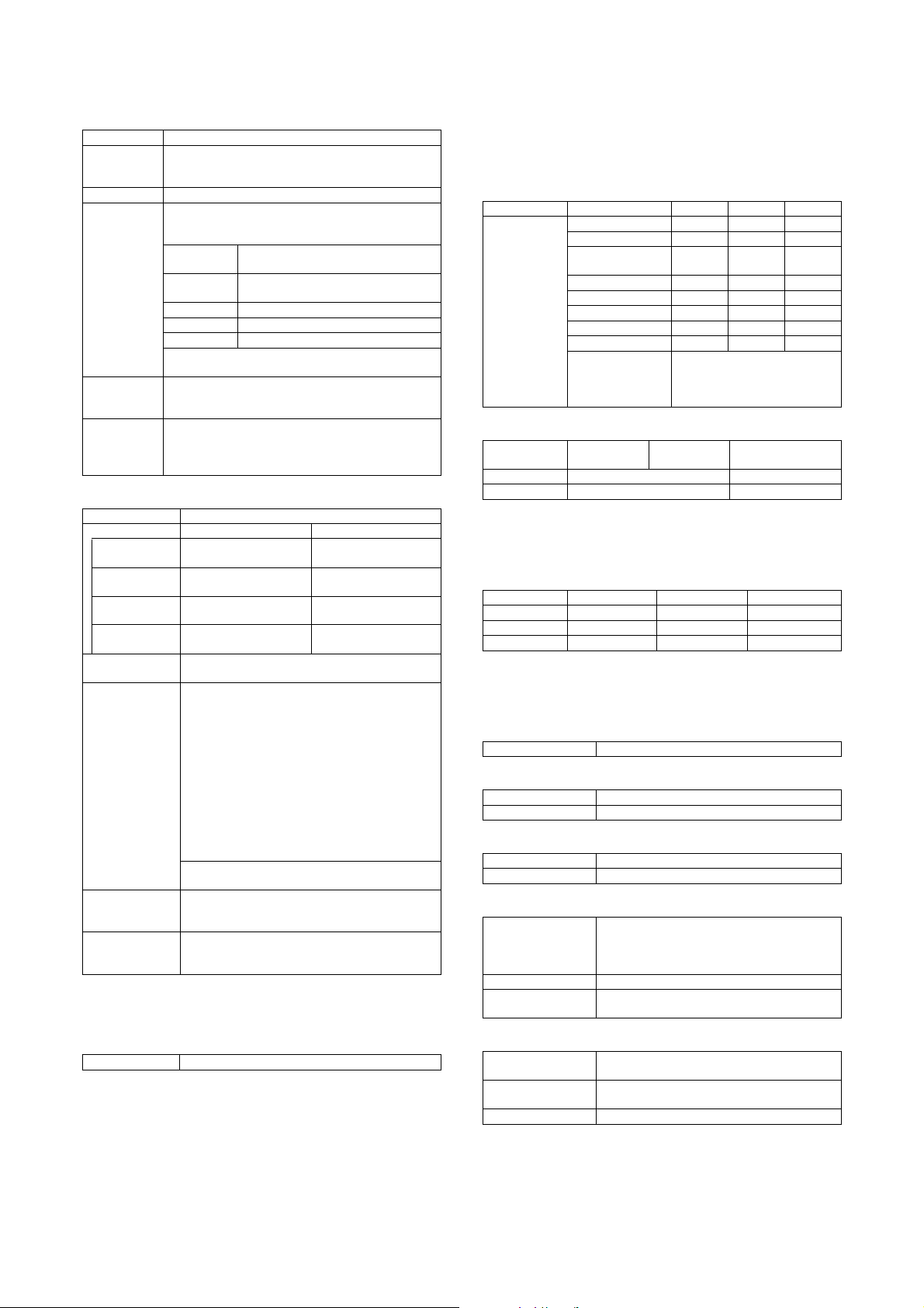
3. Environmental conditions
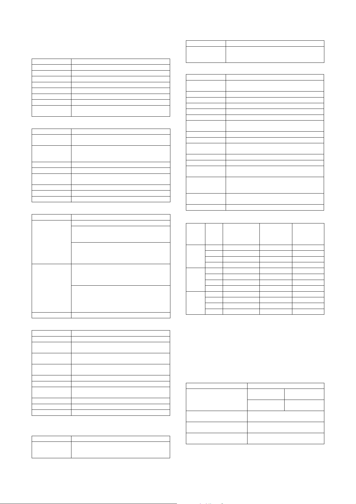
A. Environmental conditions for use of the main
Temperature: 10°C to 35°C
Humidity: 20 to 85% RH
Air pressure: 590 to 1013hPa (height: 0 to 2000m)
(Humidity)
85%
60%
20%
10 30 35
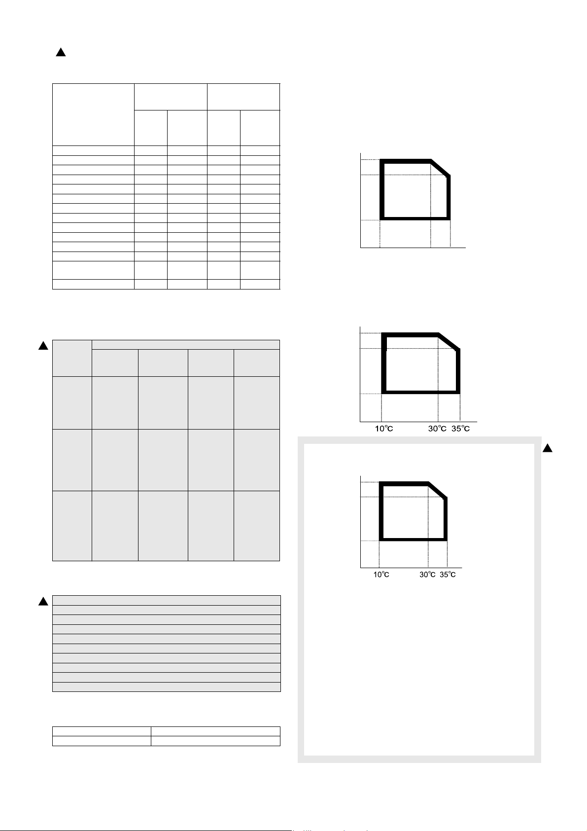
B. Environmental conditions for transit of the
main unit
–20°C to 45°C (No condensation)
Humidity (RH)
85%
60%
20%
C. Operating environmental conditions (Supply)
Humidity (RH)
85%
60%
20%
(Temperature)
2
(2) Environmental standards
2
International Energy Star Program MFP (EPA)
Environmental Choice Program (ECP)
WEEE (The machine shipped for Europe only)
Standard
Nordic swan
European ROHS regulations
Taiwan battery
(3) Noise
Operating 7.3B or less
Standby (Standby mode) 5.5B or less
D. Ambient conditions for transporting
–20qC to 45qC (No condensation)
E. Environmental conditions for storing
unopened consumable parts
–10qC to 40qC (No condensation)
F. Standard storage period of unopened
consumable parts
1) Photoconductor drum
36 months from the production month
2) Toner/Developer
24 months from the production month
MX-M700N SPECIFICATIONS 2 – 11
Page 22

MX-M700N
[3] CONSUMABLE PARTS
5GTXKEG/CPWCN
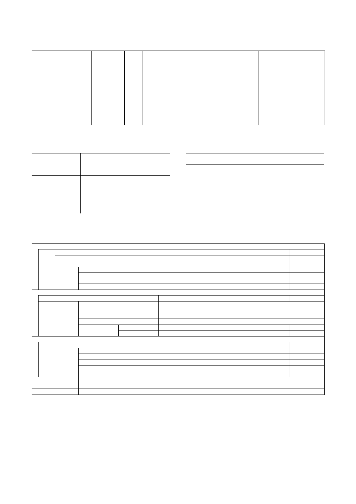
1. Supply system table
A. U.S.A, Canada, South and Central America
No. Part name Content Life Model name Packing Remark
1 Toner cartridge (Black) Toner cartridge (Black)
(Toner; Net weight 1815g) With IC chip
2 Developer (Black) Developer (Black)
(Developer; Net weight 725g)
3 Drum OPC drum x 1 62/70ppm: 300k
B. Europe affiliates (Including East Europe, Russia)/Australia/New Zealand/UK
No. Part name Content Life Model name Packing Remark
1 Toner cartridge (Black) Toner cartridge (Black)
(Toner; Net weight 1815g) With IC chip
2 Developer (Black) Developer (Black)
(Developer; Net weight 725g)
3 Drum OPC drum x 1 62/70ppm: 300k
x 10 830k (83k x 10) AR-621MTA 1 * Life setting by A4 6%
x 10 62/70ppm: 1500k
(150k x 2bags x 5)
55ppm: 1250k
(125k x 2bags x 5)
55ppm: 250k
x 10 830k (83k x 10) AR-621LT 1 * Life setting by A4 6%
x 10 62/70ppm: 1500k
(150k x 2bags x 5)
55ppm: 1250k
(125k x 2bags x 5)
55ppm: 250k
AR-620MD 1 Two bags needed.
AR-620DR 10
AR-620LD 1 Two bags needed.
AR-620DM 10
document
document
C. Asia affiliates
No. Part name Content Life Model name Packing Remark
1 Toner cartridge (Black) Toner cartridge (Black)
(Toner; Net weight 1815g) With IC chip
2 Developer (Black) Developer (Black)
(Developer; Net weight 725g)
3 Drum OPC drum x 1 62/70ppm: 300k
x 10 830k (83k x 10) AR-621CT 1 * Life setting by A4 6%
x 10 62/70ppm: 1500k
(150k x 2bags x 5)
55ppm: 1250k
(125k x 2bags x 5)
55ppm: 250k
AR-620CD 1 Two bags needed.
AR-620DR 10
document
D. Hong Kong
No. Part name Content Life Model name Packing Remark
1 Toner cartridge (Black) Toner cartridge (Black)
(Toner; Net weight 1815g) With IC chip
2 Developer (Black) Developer (Black)
(Developer; Net weight 725g)
3 Drum OPC drum x 1 62/70ppm: 300k
x 10 830k (83k x 10) AR-621CT-C 1 * Life setting by A4 6%
x 10 62/70ppm: 1500k
(150k x 2bags x 5)
55ppm: 1250k
(125k x 2bags x 5)
55ppm: 250k
AR-620CD-C 1 Two bags needed.
AR-620DR-C 10
document
E. China
No. Part name Content Life Model name Packing Remark
1 Toner cartridge (Black) Toner cartridge (Black)
(Toner; Net weight 1650g) With IC chip
2 Developer (Black) Developer (Black)
(Developer; Net weight 725g)
3 Drum OPC drum x 1 62/70ppm: 300k AR-620DR-C 1
x 1 83k (83k x 1) AR-622ST-C 10 * Life setting by A4 6%
document
x 1 62/70ppm: 150k AR-620SD-C 10 Two bags needed.
MX-M700N CONSUMABLE PARTS 3 – 1
Page 23
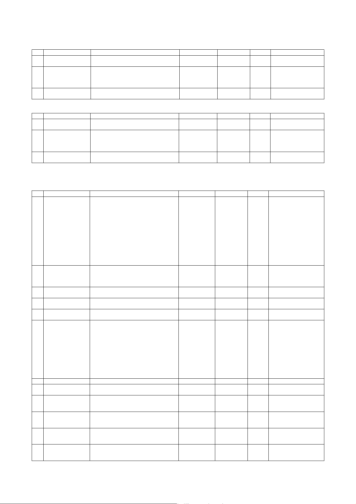
F. Middle East/Philippine
No. Part name Content Life Model name Packing Remark
1 Toner cartridge (Black) Toner cartridge (Black)
(Toner; Net weight 1815g) With IC chip
2 Developer (Black) Developer (Black)
(Developer; Net weight 725g)
3 Drum OPC drum x 1 62/70ppm: 300k
x 10 830k (83k x 10) AR-621ET 1 * Life setting by A4 6%
x 10 62/70ppm: 1500k
(150k x 2bags x 5)
55ppm: 1250k
(125k x 2bags x 5)
55ppm: 250k
AR-620CD 1 Two bags needed.
AR-620DR 10
document
G. Ta i wa n
No. Part name Content Life Model name Packing Remark
1 Toner cartridge (Black) Toner cartridge (Black)
(Toner; Net weight 1815g) With IC chip
2 Developer (Black) Developer (Black)
(Developer; Net weight 725g)
3 Drum OPC drum x 1 62/70ppm: 300k
x 10 830k (83k x 10) AR-621ET 1 * Life setting by A4 6%
x 10 62/70ppm: 1500k
(150k x 2bags x 5)
55ppm: 1250k
(125k x 2bags x 5)
55ppm: 250k
AR-620LD 1 Two bags needed.
AR-620DM 10
document
2. Maintenance parts list
A. U.S.A, Canada
No. Part name Content Life Model name Packing Remark
1 Maintenance kit 1 Side seal F
Side seal R
MC cleaning unit
Cleaner blade
Drum separation pawl
Screen grid
Toner reception seal
Charging plate
Paper dust removal unit
DV seal
DV side seal F
DV side seal R
Toner filter
2 Maintenance kit 2 Transfer cleaning roller
Transfer belt
Transfer roller
Transfer gear
3 Upper heat roller kit Upper heat roller
Fusing separation pawl (Upper)
4 Lower heat roller kit Lower heat roller
Fusing separation pawl (Lower)
5 Cleaner blade Cleaner blade x 10 300K (x 10) AR-620CB 1 AR-620CB =
6 Cleaning kit Lower CL roller DG2
CL roller SP
CL roller bearing
Auxiliary CL roller SP
CL auxiliary roller DG
Heat CL sheet base N AS
Web roller DG2
Pressure roller DG2
Web bearing
Pressure bearing
Pressure SP
7 Fusing unit Fusing UN (Heater lamp 120V) x 1 — MX-705FU1 1
8 Heat roller kit Heat roller
Heat roller bearing
9 DSPF roller kit DSPF paper feed roller
DSPF pickup roller
DSPF separation roller
10 Paper feed roller kit Main unit paper feed roller
Main unit paper feed pickup roller
Main unit paper feed separation roller
11 Staple cartridge Finisher staple x 3 5,000 times x 3 SF-SC11 20 Cartridge for AR-F15
12 Staple cartridge Saddle finisher staple x 3 2,000 times x 3 AR-SC3 40 Cartridge for AR-F16
x 1
x 1
x 1
x 1
x 4
x 1
x 1
x 1
x 1
x 1
x 1
x 1
x 1
x 1
x 1
x 1
x 1
x 1
x 6
x 1
x 4
x 10
x 20
x 40
x 20
x 10
x 10
x 10
x 10
x 20
x 20
x 20
x 1
x 2
x 1
x 1
x 1
x 1
x 1
x 1
300K AR-620KA 10
300K AR-620KB 10
300K AR-620UH 10
300K AR-620LH 10
(AR-620BL) x 10
300K (x 10) MX-705CR 1 MX-705CR =
(MX-705RC) x 10
300K AR-620HR 10
100K AR-620DF 10
100K AR-620RT 10
(Common with the cartridge
for AR-F11/F12)
(Common with the cartridge
for AR-F12)
MX-M700N CONSUMABLE PARTS 3 – 2
Page 24

B. Europe affiliates (Including East Europe, Russia) Australia/New Zealand/UK
No. Part name Content Life Model name Packing Remark
1 Maintenance kit 1 Side seal F
Side seal R
MC cleaning unit
Cleaner blade
Drum separation pawl
Screen grid
Toner reception seal
Charging plate
Paper dust removal unit
DV seal
DV side seal F
DV side seal R
Toner filter
2 Maintenance kit 2 Transfer cleaning roller
Transfer belt
Transfer roller
Transfer gear
3 Maintenance kit 3 Upper heat roller
Crimping roller EX
Upper separation pawl N
Lower separation pawl
Heat roller
Heat roller bearing
Lower CL roller DG2
CL roller SP
CL roller bearing
Auxiliary CL roller SP
CL auxiliary roller DG
Heat CL sheet base N AS
Web roller DG2
Pressure roller DG2
Web bearing
Pressure bearing
Pressure SP
4 Fusing unit Fusing UN (Heater lamp 230V) x 1 — MX-705FU 1
5 DSPF roller kit DSPF paper feed roller
DSPF pickup roller
DSPF separation roller
6 Paper feed roller kit Main unit paper feed roller
Main unit paper feed pickup roller
Main unit paper feed separation roller
7 Staple cartridge Finisher staple x 3 5,000 times x 3 SF-SC11 20 Cartridge for AR-F15
8 Staple cartridge Saddle finisher staple x 3 2,000 times x 3 AR-SC3 40 Cartridge for AR-F16
x 1
x 1
x 1
x 1
x 4
x 1
x 1
x 1
x 1
x 1
x 1
x 1
x 1
x 1
x 1
x 1
x 1
x 1
x 1
x 6
x 4
x 1
x 2
x 1
x 2
x 4
x 2
x 1
x 1
x 1
x 1
x 2
x 2
x 2
x 1
x 1
x 1
x 1
x 1
x 1
300K AR-620KA 10
300K AR-620KB 10
300K MX-705KC 5
100K AR-620DF 10
100K AR-620RT 10
(Common with the cartridge
for AR-F11/F12)
(Common with the cartridge
for AR-F12)
MX-M700N CONSUMABLE PARTS 3 – 3
Page 25

C. Middle East/Asia/South and Central America
No. Part name Content Life Model name Packing Remark
1 Maintenance kit 1 Side seal F
Side seal R
MC cleaning unit
Cleaner blade
Drum separation pawl
Screen grid
Toner reception seal
Charging plate
Paper dust removal unit
DV seal
DV side seal F
DV side seal R
Toner filter
2 Maintenance kit 2 Transfer cleaning roller
Transfer belt
Transfer roller
Transfer gear
3 Maintenance kit 3 Upper heat roller
Crimping roller EX
Upper separation pawl N
Lower separation pawl
Heat roller
Heat roller bearing
Lower CL roller DG2
CL roller SP
CL roller bearing
Auxiliary CL roller SP
CL auxiliary roller DG
Heat CL sheet base N AS
Web roller DG2
Pressure roller DG2
Web bearing
Pressure bearing
Pressure SP
4 Fusing unit Fusing UN (Heater lamp 230V) x 1 — MX-705FU 1
5 DSPF roller kit DSPF paper feed roller
DSPF pickup roller
DSPF separation roller
6 Paper feed roller kit Main unit paper feed roller
Main unit paper feed pickup roller
Main unit paper feed separation roller
7 Staple cartridge Finisher staple x 3 5,000 times x 3 SF-SC11 20 Cartridge for AR-F15
8 Staple cartridge Saddle finisher staple x 3 2,000 times x 3 AR-SC3 40 Cartridge for AR-F16
x 1
x 1
x 1
x 1
x 4
x 1
x 1
x 1
x 1
x 1
x 1
x 1
x 1
x 1
x 1
x 1
x 1
x 1
x 1
x 6
x 4
x 1
x 2
x 1
x 2
x 4
x 2
x 1
x 1
x 1
x 1
x 2
x 2
x 2
x 1
x 1
x 1
x 1
x 1
x 1
300K AR-620KA 10
300K AR-620KB 10
300K MX-705KC 5
100K AR-620DF 10
100K AR-620RT 10
(Common with the cartridge
for AR-F11/F12)
(Common with the cartridge
for AR-F12)
MX-M700N CONSUMABLE PARTS 3 – 4
Page 26

D. Hong Kong
No. Part name Content Life Model name Packing Remark
1 Maintenance kit 1 Side seal F
Side seal R
MC cleaning unit
Cleaner blade
Drum separation pawl
Screen grid
Toner reception seal
Charging plate
Paper dust removal unit
DV seal
DV side seal F
DV side seal R
Toner filter
2 Maintenance kit 2 Transfer cleaning roller
Transfer belt
Transfer roller
Transfer gear
3 Maintenance kit 3 Upper heat roller
Crimping roller EX
Upper separation pawl N
Lower separation pawl
Heat roller
Heat roller bearing
Lower CL roller DG2
CL roller SP
CL roller bearing
Auxiliary CL roller SP
CL auxiliary roller DG
Heat CL sheet base N AS
Web roller DG2
Pressure roller DG2
Web bearing
Pressure bearing
Pressure SP
4 Fusing unit Fusing UN (Heater lamp 230V) x 1 — MX-705FU 1
5 DSPF roller kit DSPF paper feed roller
DSPF pickup roller
DSPF separation roller
6 Paper feed roller kit Main unit paper feed roller
Main unit paper feed pickup roller
Main unit paper feed separation roller
7 Staple cartridge Finisher staple x 3 5,000 times x 3 SF-SC11 20 Cartridge for AR-F15
8 Staple cartridge Saddle finisher staple x 3 2,000 times x 3 AR-SC3 40 Cartridge for AR-F16
x 1
x 1
x 1
x 1
x 4
x 1
x 1
x 1
x 1
x 1
x 1
x 1
x 1
x 1
x 1
x 1
x 1
x 1
x 1
x 6
x 4
x 1
x 2
x 1
x 2
x 4
x 2
x 1
x 1
x 1
x 1
x 2
x 2
x 2
x 1
x 1
x 1
x 1
x 1
x 1
300K AR-620KA 10
300K AR-620KB 10
300K MX-705KC 5
100K AR-620DF 10
100K AR-620RT 10
(Common with the cartridge
for AR-F11/F12)
(Common with the cartridge
for AR-F12)
MX-M700N CONSUMABLE PARTS 3 – 5
Page 27

E. Taiwan
No. Part name Content Life Model name Packing Remark
1 Maintenance kit 1 Side seal F
Side seal R
MC cleaning unit
Cleaner blade
Drum separation pawl
Screen grid
Toner reception seal
Charging plate
Paper dust removal unit
DV seal
DV side seal F
DV side seal R
Toner filter
2 Maintenance kit 2 Transfer cleaning roller
Transfer belt
Transfer roller
Transfer gear
3 Maintenance kit 3 Upper heat roller
Crimping roller EX
Upper separation pawl N
Lower separation pawl
Heat roller
Heat roller bearing
Lower CL roller DG2
CL roller SP
CL roller bearing
Auxiliary CL roller SP
CL auxiliary roller DG
Heat CL sheet base N AS
Web roller DG2
Pressure roller DG2
Web bearing
Pressure bearing
Pressure SP
4 Fusing unit Fusing UN (Heater lamp 100V) x 1 — MX-705FU2 1
5 DSPF roller kit DSPF paper feed roller
DSPF pickup roller
DSPF separation roller
6 Paper feed roller kit Main unit paper feed roller
Main unit paper feed pickup roller
Main unit paper feed separation roller
7 Staple cartridge Finisher staple x 3 5,000 times x 3 SF-SC11 20 Cartridge for AR-F15
8 Staple cartridge Saddle finisher staple x 3 2,000 times x 3 AR-SC3 40 Cartridge for AR-F16
x 1
x 1
x 1
x 1
x 4
x 1
x 1
x 1
x 1
x 1
x 1
x 1
x 1
x 1
x 1
x 1
x 1
x 1
x 1
x 6
x 4
x 1
x 2
x 1
x 2
x 4
x 2
x 1
x 1
x 1
x 1
x 2
x 2
x 2
x 1
x 1
x 1
x 1
x 1
x 1
300K AR-620KA 10
300K AR-620KB 10
300K MX-705KC 5
100K AR-620DF 10
100K AR-620RT 10
(Common with the cartridge
for AR-F11/F12)
(Common with the cartridge
for AR-F12)
MX-M700N CONSUMABLE PARTS 3 – 6
Page 28
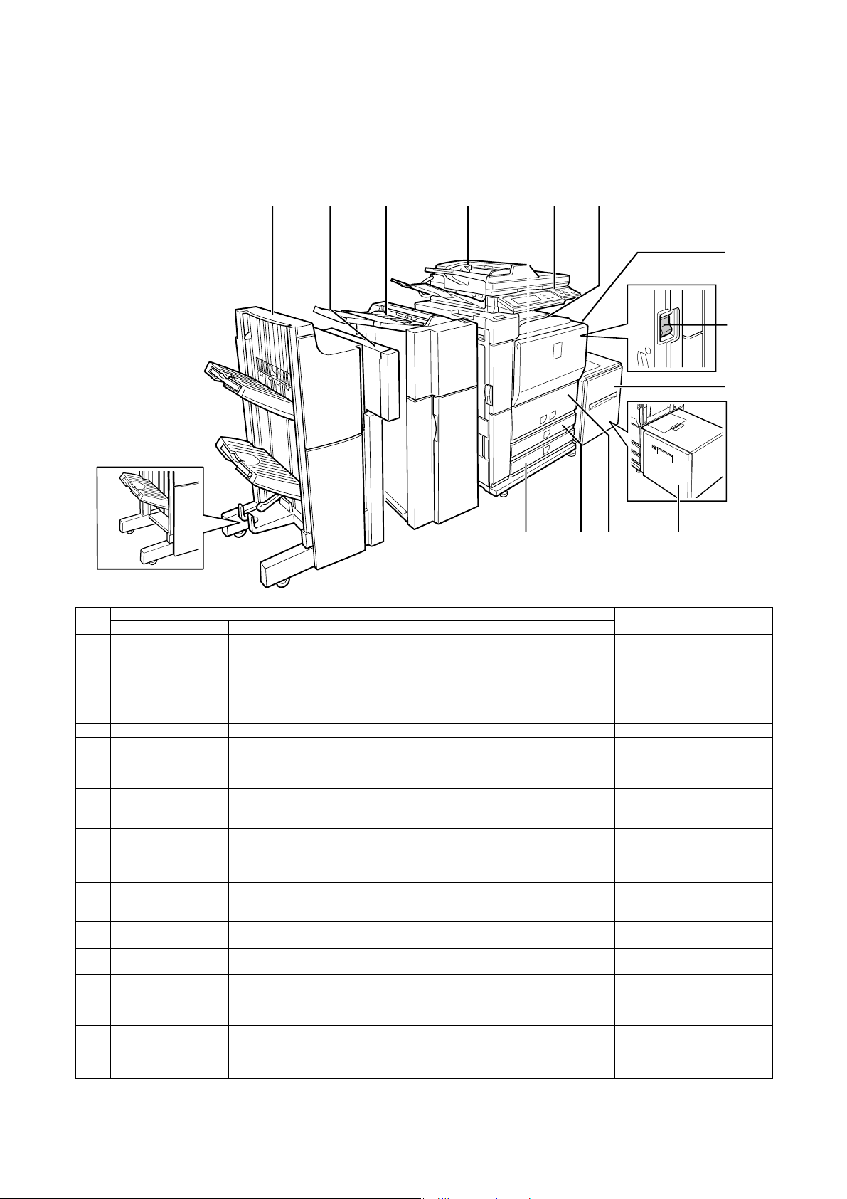
MX-M700N
[5] EXTERNAL VIEW AND INTERNAL STRUCTURE
5GTXKEG/CPWCN
1. Identification of each section and functions
A. External view
123 4 567
8
9
10
1314 12 11
Finisher
No.
1 Saddle stitch finisher
2 Punch module
3 Inserter
4 Automatic document
5 Front cover Open to replace toner cartridge.
6 Operation panel Performs various setting, display, and simulation operations.
7 Center tray Finished sheets are deposited here
8 Bypass tray Special papers (including transparency film) and copy paper can be fed from the bypass
9 Power switch Turns the power on and off.
10 Paper feed tray 5
11 Paper feed tray 5
12 Paper feed trays 1, 2 The trays hold paper.
13 Paper feed tray 3 Tray 3 holds. Approximately 500 sheets of standard (20 lbs. (80 g/m
14 Paper feed tray 4 Tray 4 holds. Approximately 500 sheets of standard (20 lbs. (80 g/m
Name Funciton/Operation
*1
Finisher
*1
feeder
(Large capasity tray)
(Large capasity tray)
*1
/
The finisher and the saddle stitch finisher include the offset function, which offsets each
set of copies from the preceding set for easy separation. Each set of sorted copies can
also be stapled.
The saddle stitch finisher can automatically staple at the center line of a set of copies
and fold the pages to create a pamphlet.
A punch unit can be installed to add punch holes to copioes, and an inserter can be
*1
installed to insert blank pages at specified pages.
Adds punch holes to printed pages.
The inserter enables blank sheets or printed sheets to be added to copy and print output
as covers or inserts without printing. Printed output can also be fed one set at a time
from the inserter for stapling or punching without performing stapling or staple sorting
finishing.
This automatically feeds and scans multiple sheet originals. Both sides of two-sided
originals can be scanned at once.
tray.
If the power does not come on when the power switch is turned on, check the main
power switch to see if it is turned on.
The large capacity tray can hold up to 3,500 sheets of commonly used (8-1/2” ✕ 11 ” ,
*1
B5, A4) any standard paper (20 lbs. (80 g/m
The large capacity tray can hold up to 3000 sheets of 20 lbs. (80 g/m2) paper.
*1
Approximately 800 sheets of standard 8-1/2” ✕ 11” or A4 size paper (20 lbs. (80 g/m
can be loaded in tray 1, and approximately 1200 sheets of standard 8-1/2” ✕ 11 ” , A 4 or
B5 size paper (20 lbs. (80 g/m
loaded in this tray. Tabbed paper and transparencies can also be loaded.
loaded in this tray.
*1: 1, 2, 3, 10 and 11 are peripheral devices. For information on these devices, see the explanations of the devices in the manual.
Parts
2
)).
2
)) can be loaded in tray 2.
2
)) paper can be
2
)) paper can be
NOTE
2
))
MX-M700N EXTERNAL VIEW AND INTERNAL STRUCTURE 5 – 1
Page 29
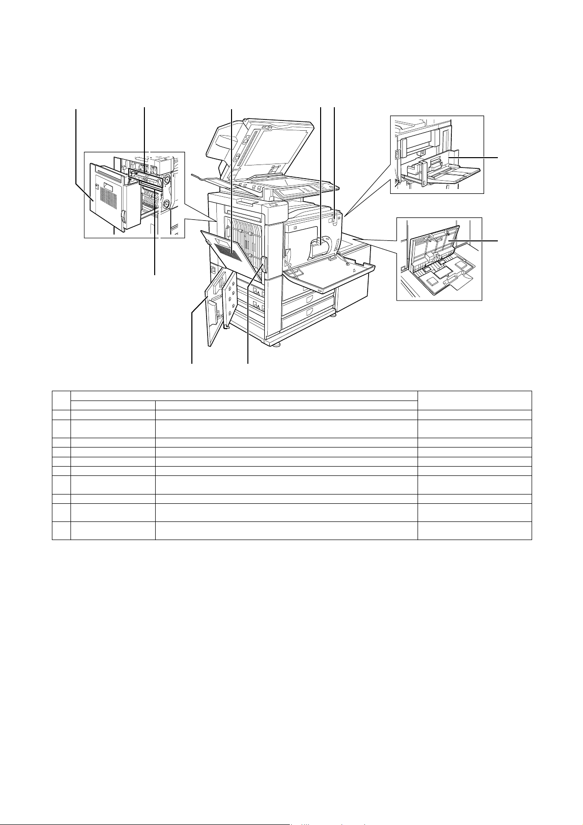
B. Internal operation parts
12 3 45
10
6
7
89
No.
1 Duplex unit Open the cover to remove a misfeed from the fusing/duplex unit.
2 Fusing unit Toner images are fused here. The fusing unit is hot. Take care in
3 Cover of the duplex unit Open when a misfeed has occurred in the duplex unit.
4 Toner cartridge The toner cartridge must be replaced by the indication on the operation panel.
5 Main power switch Keep this switch turned on when the fax option or network scanner option is installed.
6 Right side cover Open when a misfeed has occurred in bypass tray or large capacity tray.
7 Upper cover of large
8 Left side cover release Push this knob up to open the left side cover.
9 Left cover of paper
10 OPC drum Images are formed on the photoconductive drum. Do not touch or damage the
Name Funciton/Operation
Open when a misfeed has occurred in large capacity tray.
capacity tray
Open this cover to remove paper misfed in the tray 3 and tray 4.
drawer
Parts
NOTE
removing misfed paper.
photoconductive drum.
MX-M700N EXTERNAL VIEW AND INTERNAL STRUCTURE 5 – 2
Page 30
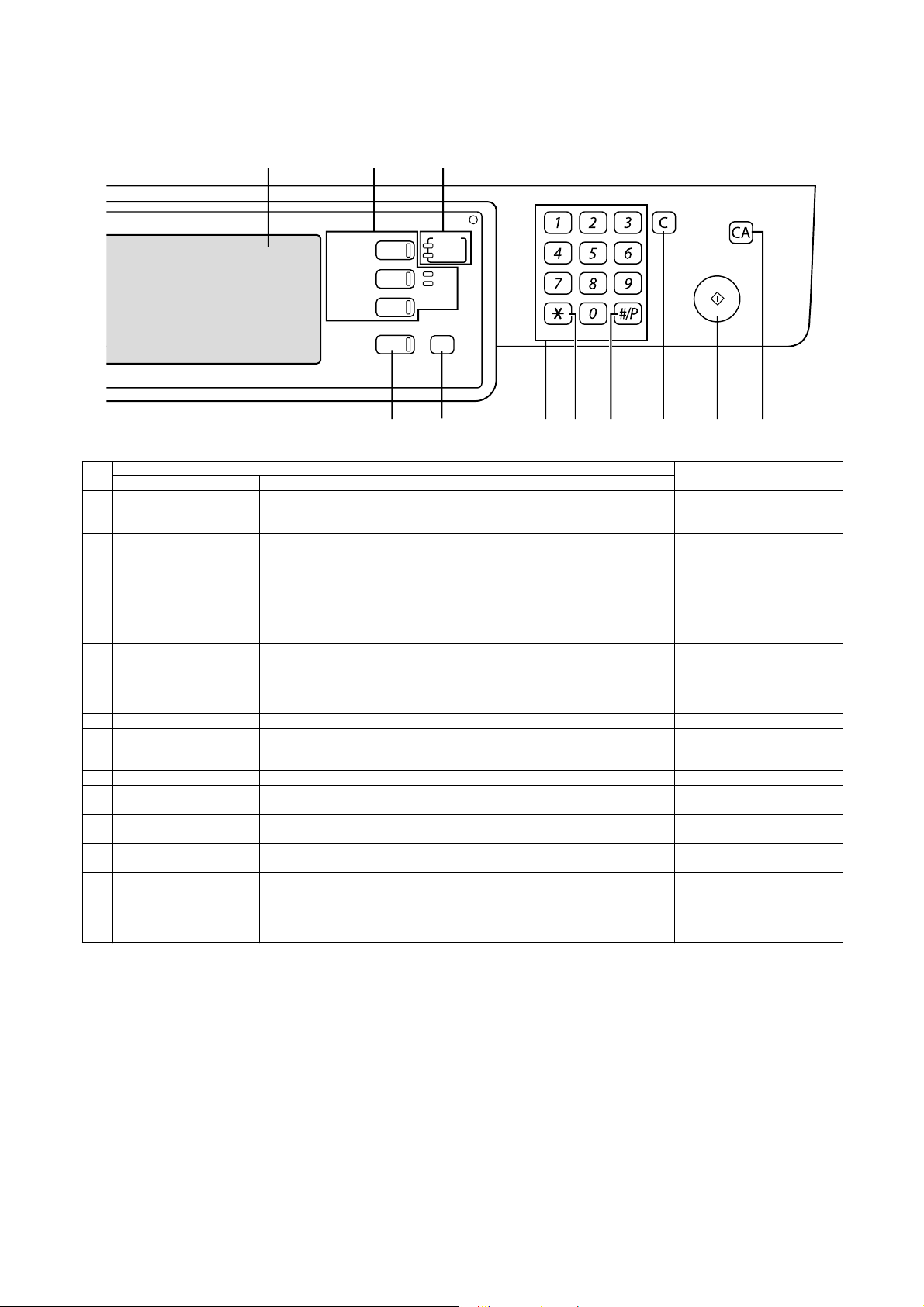
C. Operation, display parts
123
DOCUMENT
FILING
IMAGE SEND
COPY
JOB STATUS
PRINT
READY
DATA
LINE
DATA
SYSTEM
SETTINGS
LOGOUT
4 5 6 7 8 9 10 11
No.
Name Funciton/Operation
1 Touch panel The machine status, messages and touch keys are displayed on the panel. The
document filing, copy, network scanner
Parts
*1
, and fax*2, Internet fax*3 functions are used
by switching to the screen for the desired function. See the following page.
2 Mode select key s and
indicators
Use to change modes and the corresponding display on the touch panel.
[DOCUMENT FILING] key
Press to select the document filing mode.
[IMAGE SEND] key/LINE indicator/DATA indicator
Press to change the display to network scanner mode
*3
mode
.
*1
, fax mode*2 or Internet fax
[COPY] key
Press to select the copy mode.
3 PRINT mode indicators • READY indicator
Print data can be received when this indicator is lit.
• DATA indicator
Lights up or blinks when print data is being received. Also lights up or blinks when
printing is being performed.
4 [JOB STATUS] key Press to display the current job status.
5 [SYSTEM SETTINGS] key This is used to store, edit, and delete user names and folder names for the document
filing function, and to configure the administrator settings and printer configuration
settings.
6 Numeric keys Use to enter number values for various settings.
7 [*] key ([LOGOUT] key) This key is used in copy mode, document filing mode, network scanner mode
8 [#/P] key This is used as a program key when using the copy function, and to dial when using
9 [C] key (Clear key) This key is used in copy mode, document filing mode, network scanner mode
10 [START] key Use this key to start copying in copy mode, scan a document in network scanner
11 [CA] key (Clear all key) This key is used in copy mode, document filing mode, network scanner mode*1, fax
*2
mode
, and Internet fax mode*3.
the fax function
mode
mode
mode
*2
.
*2
, and Internet fax mode*3.
*1
, or scan a document for transmission in fax mode*2 or Internet fax mode*3.
*2
, and Internet fax mode*3.
*1
*1
Use the key to cancel settings and perform an operation from the initial machine state.
*1: When the network scanner option is installed.
*2: When the fax option is installed.
*3: When the Internet fax option is installed.
NOTE
, fax
, fax
MX-M700N EXTERNAL VIEW AND INTERNAL STRUCTURE 5 – 3
Page 31

D. Job status screen (common to print, copy, fax, network scan and internet fax)
This screen is displayed when the [JOB STATUS] key on the operation panel is pressed.
This screen can be used to display the “JOB QUEUE” (showing stored jobs and the current job) or the “COMPLETE” job list (showing finished
jobs). This screen is used to check jobs, move a job to the top of the JOB QUEUE, or delete a job.
*1
"JOB QUEUE" screen
12
"COMPLETE"
job screen
JOB QUEUE
COPY
COPY
Suzuki
066211221
PRINT JOB
SETS / PROGRESS
020 / 001
020 / 000
020 / 000
002 / 000
SCAN
STATUS
COPYING
PAPER EMPTY
WAITING
WAITING
FAX JOB
1/1
JOB QUEUE
COMPLETE
DETAIL
PRIORITY
STOP/DELETE
INTERNET-FAX
34567891011
No.
1 Job list The displayed jobs in the job list are themselves operation keys. To cancel printing or to
Name Function/Operation
give a job the highest print priority, touch the relevant job key to select the job and
execute the desired operation using the keys described in 8 and 9.
This shows the current job and the jobs waiting to be run. The icons to the left of the jobs
in the queue show the job mode. The document filing reprint job icon is highlighted.
Note that the icon does not become highlighted during retransmission of a fax/image
transmission job.
(Displayed in the touch panel)
Print mode Copy mode
SCAN mode
Scan to e-mail job Scan to FTP job
Scan to Desktop job
Scan to Network folder job
JOB QUEUE
COMPLETE
DETAIL
CALL
INTERNET-FAX
NOTE
*1: “PAPER EMPTY” in the job
status display
When a job status display indicates
“PAPER EMPTY”, the specified
paper size for the job is not loaded
in any of the trays.
In this case, the job will be
suspended until the required paper
is loaded. Other stored jobs will be
printed (if possible) until the
required paper is loaded.
(Other jobs will not be printed if the
paper runs out during printing.) If
you need to change the paper size
because the specified paper size is
not available, touch the current job
key to select it and then touch the
[DETAIL] key described in 10.
Fax mode
Fax send job Fax reception job
PC-FAX send job
Internet Fax mode
i-Fax send job i-Fax reception job
PC-Internet Fax send job
2 Mode select key This switches the job list display between “JOB QUEUE” and “COMPLETE”.
3 [PRINT JOB] key This displays the print job list of print mode (copying, printing, fax reception, Internet fax
4 [SCAN] key This displays the transmission status and finished jobs of scan mode (Scan to e-mail,
5 [FAX JOB] key This displays the transmission/reception status and finished jobs of fax mode (fax and
“JOB QUEUE”: Shows stored jobs and the job in progress.
“COMPLETE”: Shows finished jobs.
Files saved using the “FILE” and “QUICK FILE” functions and finished broadcast
transmission jobs appear as keys in the finished job screen.
The “FILE” or “QUICK FILE” job keys in the finished job screen can be touched, followed
by the [CALL] key, to call up a finished job and print or transmit it. A finished broadcast
transmission job key can be touched followed by the [DETAIL] key to check the result of
the transmission.
reception, and self printing).
Scan to FTP, and Scan to Desktop) when the network scanner option is installed.
PC-Fax) when the fax option is installed.
MX-M700N EXTERNAL VIEW AND INTERNAL STRUCTURE 5 – 4
Page 32

No.
6 Display switching keys Use to switch the page of the displayed job list.
7 [INTERNET-FAX] key This displays the transmission/reception status and finished jobs of Internet fax mode and
8 [STOP/DELETE] key Use to cancel or delete the current job or delete the selected reserved job. Note that
9 [PRIORITY] key A stored job in the “JOB QUEUE” job list can be printed ahead of all other stored jobs by
10 [DETAIL] key This shows detailed information on the selected job. Files saved using the “FILE” and
11 [CALL] key When this key is touched after selecting a job in the COMPLETE job status screen (a job
Name Function/Operation
PC Internet fax mode when the network scanner option is installed.
printing of received faxes and received Internet faxes cannot be canceled or deleted.
selecting the job and then touching this key.
“QUICK FILE” functions and finished broadcast transmission jobs appear as keys in the
finished job screen. A Quick File in the finished job screen or the [Filing] key can be
touched, followed by the [CALL] key, to call up a finished job and print or transmit it. A
finished broadcast transmission job key can be touched followed by the [DETAIL] key to
check the result of the transmission.
stored using the FILE or QUICK FILE keys of the document filing function), the “JOB
SETTINGS” menu screen appears to let you resend or reprint the finished job.
(Displayed in the touch panel)
NOTE
MX-M700N EXTERNAL VIEW AND INTERNAL STRUCTURE 5 – 5
Page 33
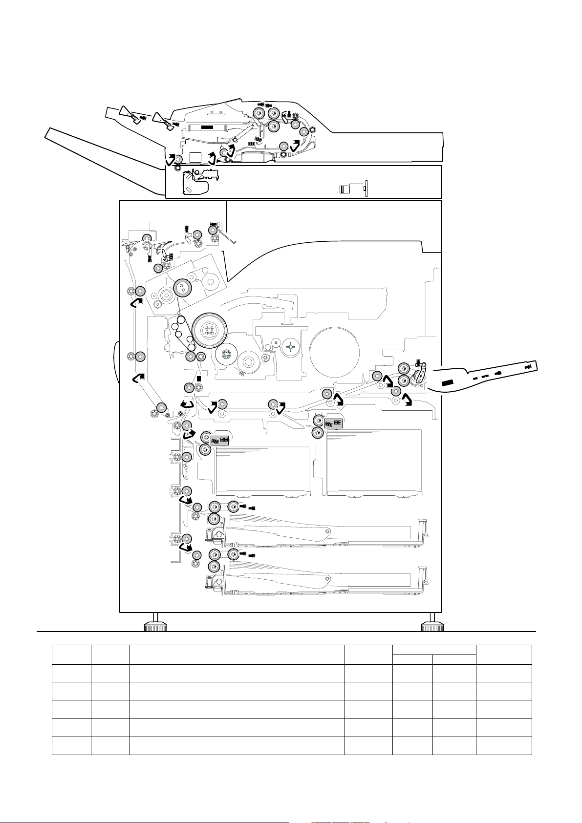
E. Sensor/detector
M1PFD
M1LUD
M1PED
M2LUD
M2PED
M2PFD
T2LUD
T2PED
T1LUD
T1PED
MPED
MPFD1
MPRD1
MPFD2
MPRD2
T1PPD
PPD
LPPD
PFD2
APPD1
APPD2
AINPD
POD2
POD3
POD1
MPLD2
MPLD1
MTOP1
MTOP2
SPLS2
SPLS1
SPED2
SPED1
SPPD1
SPPD2
SPPD3
SPPD4
SPOD
SPWS
STUD
STLD
SPLS2
SPOD
SPLS1
SPWS
SPPD4
SPPD3
SPED1
STLD
SPED2
STUD
SPPD1
SPPD2
AINPD
APPD1
APPD2
T1PPD
POD2
POD1
PFD2
POD3
PPD
MPRD2
T1PED
M1PFD
T1LUD
M1LUD
MPRD1
M1PED
T2PED
MPFD2
T2LUD
MPFD1
MPED
LPPD
MPFPWS
MTOP1
MTOP2
MPLD1
MPLD2
M2PFD
M2LUD
M2PED
Code
AINPD AINPD Duplex (ADU) paper entry
APPD1 APPD1 Duplex (ADU) paper pass
APPD2 APPD2 Duplex (ADU) paper pass
LPPD LPPD LCC paper pass detector Detection of paper entry from LCC Transmission
M1LUD M1LUD Paper tray upper limit detector
Signal
name
Name Function/Operation Type
detector
detector 1
detector 2
(Paper feed tray 3)
Duplex (ADU) paper entry detection,
detection of paper exit to finisher
Duplex (ADU) upstream paper pass
detection
Duplex (ADU) midstream paper pass
detection
Paper tray upper limit detection
(Paper feed tray 3)
Transmission
type
Transmission
type
Transmission
type
type
Transmission
type
MX-M700N EXTERNAL VIEW AND INTERNAL STRUCTURE 5 – 6
Connector level
“L” “H”
Paper
pass
Paper
pass
Paper
pass
Paper
pass
– Upper limit
– Paper transport
system sensor
– Paper transport
system sensor
– Paper transport
system sensor
– Paper transport
system sensor
detection
Paper feed tray
system sensor
NOTE
Page 34

Code
M1PED M1PED Paper empty detector
M1PFD M1PFD Paper pass detector
M2LUD M2LUD Paper tray upper limit detector
M2PED M2PED P aper tray upper limit detector
M2PFD M2PFD Paper pass detector
MPED MPED Manual feed paper empty
MPFD1 MPFD1 Manual feed paper pass
MPFD2 MPFD2 Manual feed paper pass
MPFPWS MPFPWS Manual feed paper width
MPLD1 MPLD1 Manual feed paper length
MPLD2 MPLD2 Manual feed paper length
MPRD1 MPRD1 Paper feed tray 2 paper pass
MPRD2 MPRD2 Paper feed tray 2 paper pass
MTOP1 MTOP1 Manual tray pull-out position
MTOP2 MTOP2 Manual tray pull-out position
PFD2 PFD2 Paper pass detector 2 Paper pass detection (Left door unit)
POD1 POD1 Paper exit detector 1 Paper exit detection from fusing Transmission
POD2 POD2 Paper exit detector 2 Paper pass detection from paper exit Transmission
POD3 POD3 Paper exit detector 3 Paper exit detection to upper section
PPD PPD Resist roller front paper pass
SPED1 SPED1 DSPF document empty
SPED2 SPED2 DSPF document detector DSPF document detection Transmission
SPLS1 SPLS1 DSPF document length
SPLS2 SPLS2 DSPF document length
SPOD SPOD DSPF paper exit detector DSPF paper exit detection Transmission
SPPD1 SPPD1 DSPF document paper pass
SPPD2 SPPD2 DSPF document paper pass
SPPD3 SPPD3 DSPF document paper pass
SPPD4 SPPD4 DSPF document paper pass
SPWS SPWS DSPF document size (Width)
STLD STLD DSPF document tray lower
STUD STUD DSPF document tray upper
T1LUD T1LUD Paper feed tray upper limit
T1PED T1PED Paper empty detector
T1PPD T1PPD Paper pass detector
Signal
name
Name Function/Operation Type
(Paper feed tray 3)
(Paper feed tray 3)
(Paper feed tray 4)
(Paper feed tray 4)
(Paper feed tray 4)
detector
detector 1
detector 2
detector
detector 1
detector 2
detector 1
detector 2
detector 1
detector 2
detector
detector
detector 1
detector 2
detector 1
detector 2
detector 3
detector 4
detection analog data detector
limit detector
limit detector
detector
(Paper feed tray 1)
(Paper feed tray 1)
(Paper feed tray 1)
Paper empty detection
(Paper feed tray 3)
Paper feed tray 3 paper pass
detection
Paper tray upper limit detection
(Paper feed tray 4)
Paper empty detection
(Paper feed tray 4)
Paper feed tray 4 paper pass
detection
Manual paper feed tray paper empty
detection
Manual tray paper pass detection Transmission
Manual tray and LCC paper pass
detection
Manual feed paper width detection Volume
Manual paper feed tray paper length
detection (Paper feed side)
Manual paper feed tray paper length
detection (Outside)
Manual feed/paper feed tray 2/
LCC paper pass detection
Manual feed/paper feed tray 2/
LCC paper pass detection
Manual paper feed tray pull-out
position detection (Storing position)
Manual paper feed tray pull-out
position detection (Pull-out position)
from duplex (ADU)/
No.1, 3, 4 paper feed
paper exit tray (Full detection)
Paper pass detection in front of resist
roller
DSPF document empty detection Transmission
DSPF document length detection
(Short)
DSPF document length detection
(Long)
DSPF document paper pass
detection 1
DSPF document paper pass
detection 2
DSPF document paper pass
detection 3
DSPF document paper pass
detection 4
DSPF document size (Width)
detection
DSPF document tray lower limit
detection
DSPF document tray upper limit
detection
Paper feed tray upper limit
(Paper feed tray 1)
Paper presence detection
(Paper feed tray 1)
Paper pass detection from paper feed
tray 1
Transmission
type
Transmission
type
Transmission
type
Transmission
type
Transmission
type
Transmission
type
type
Transmission
type
resistor
Transmission
type
Transmission
type
Transmission
type
Transmission
type
Contact type Storage – Manual paper
Contact type Pull-out – Manual paper
Transmission
type
type
type
Transmission
type
Reflection
type
type
type
Transmission
type
Transmission
type
type
Transmission
type
Transmission
type
Transmission
type
Transmission
type
Volu me
resistor
Transmission
type
Transmission
type
Transmission
type
Transmission
type
Transmission
type
Connector level
“L” “H”
Paper
empty
Paper
pass
Paper
empty
Paper
pass
Paper
present
Paper
pass
Paper
pass
Paper
pass
Paper
pass
Paper
pass
Paper
pass
Paper
pass
Paper
pass
Paper
present
Paper
present
Paper exit Sensor
Paper
present
Paper
present
Paper
present
Paper
present
Upper limit – Paper feed tray
Paper
empty
Paper
pass
Paper
present
– Paper transport
– Upper limit
detection
Paper
present
– Paper transport
Paper
empty
– Paper transport
– Paper transport
– – Analog detector
– Paper
present
– Paper
present
– Paper transport
– Paper transport
– Paper transport
– Paper transport
– Paper transport
– Paper pass
(Full
detection)
– Paper transport
Paper
present
Paper
present
– – Other detector
Lower limit Sensor
Upper limit Sensor
Paper
present
– Paper transport
NOTE
Paper feed tray
system sensor
system sensor
Paper feed tray
system sensor
Paper feed tray
system sensor
system sensor
Manual paper
feed unit
system sensor
system sensor
Manual paper
feed unit
Manual paper
feed unit
system sensor
system sensor
feed unit
feed unit
system sensor
system sensor
system sensor
Paper transport
system sensor
system sensor
Sensor
Sensor
Sensor
Sensor
Sensor
Sensor
Sensor
Sensor
system sensor
Paper feed tray
system sensor
system sensor
MX-M700N EXTERNAL VIEW AND INTERNAL STRUCTURE 5 – 7
Page 35

Code
SOCD
SCOV
DSW-R
DSW-L
TH-CL
DMS
PCS
RTH3
RTH1
WEBEND
RTH2
THPS2
TLS
TH-EX
HUS-DV
TH-DV
TNCA
TCS
TANSET
DSW-ADU
M1PWS
HUS-TC
M1SS4
M2
SS4
MHPS
PDSELX
LEDX
M1SS2
M1SS3
M2SS2
M2SS3
T2LUD T2LUD Paper feed tray upper limit
T2PED T2PED Paper empty detector
Signal
name
Name Function/Operation Type
detector (Paper feed tray 2)
(Paper feed tray 2)
Paper feed tray upper limit
(Paper feed tray 2)
Paper presence detection
(Paper feed tray 2)
SCOV
Transmission
type
Transmission
type
Connector level
“L” “H”
Upper limit – Paper feed tray
Paper
empty
Paper
present
NOTE
system sensor
Paper feed tray
system sensor
DSW-ADU
TH-EX
RTH3
DSW-L
TLS
SOCD
MHPS
RTH1
RTH2
THPS2
PCS
WEBEND
TH-CL
HUS-TC
HUS-DV
TH-DV
DMS
TCS
TFSD
LEDX
PDSELX
OCSW
TH-RA
DSW-F
DSW-R
T2SPD
T1SPD
DSW-DSK
TANSET
M1SS1
M1SS3
M1SS2
M1SS4
M1PWS
M1SPD
M2SS1
M2SPD
M2SS3
M2SS2
M2SS4
Code
CISTH CISTH CIS temperature sensor CIS temperature detection Thermistor – – Not used.
DMS DMS OPC drum marking sensor OPC drum mark detection Reflection
Signal
name
Name Function/Operation Type
type
Connector level
“L” “H”
– – Analog detector
NOTE
MX-M700N EXTERNAL VIEW AND INTERNAL STRUCTURE 5 – 8
Page 36

Code
DSWADU
DSW-DSK DSW-DSK Left door open/close
DSW-F DSW-F Front door open/close
DSW-L DSW-L Left door open/close
DSW-R DSW-R Manual feed open/close
HUS-DV HUS-DV Developing humidity
HUS-TC HUS-TC Process humidity sensor Process section peripheral humidity
LEDX LEDX Document size sensor
M1PWS M1PWS Paper feed tray paper
M1SPD M1SPD Paper remaining quantity
M1SS1 M1SS1 Paper size detector
M1SS2 M1SS2 Paper size detector
M1SS3 M1SS3 Paper size detector
M1SS4 M1SS4 Paper size detector
M2SPD M2SPD Paper remaining quantity
M2SS1 M2SS1 Paper size detector
M2SS2 M2SS2 Paper size detector
Signal
name
DSWADU
Name Function/Operation Type
Duplex (ADU) cover open/
close detector
detector (Desk section)
detector
detector
detector
sensor
(Light emitting) (LED)
width detector
(Paper feed tray 3)
detector (Paper feed tray3)
(Paper feed tray 3)
(Paper feed tray 3)
(Paper feed tray 3)
(Paper feed tray 3)
detector (Paper feed tray4)
(Paper feed tray 4)
(Paper feed tray 4)
Duplex (ADU) cover open/close
detection
Left door open/close detection
(Desk section)
Front door open/close detection Micro switch Front door
Left door open/close detection Micro switch Left door,
Manual feed open/close detection Micro switch
Developing section peripheral
humidity detection
detection
Document size detection LED LED – – Other detector
Multi paper feed tray paper width
detection (Paper feed tray 3)
Paper remaining quantity detection
(Paper feed tray 3)
Paper size detection by combination
of ON/OFF of MISS 1 – 4
Paper size detection by combination
of ON/OFF of MISS 1 – 4
Paper size detection by combination
of ON/OFF of MISS 1 – 4
Paper size detection by combination
of ON/OFF of MISS 1 – 4
Paper remaining quantity detection
(Paper feed tray 4)
Paper size detection by combination
of ON/OFF of MISS 1 – 4
Paper size detection by combination
of ON/OFF of MISS 1 – 4
Connector level
Transmission
type
Transmission
type
(NC)
Humidity
sensor
Humidity
sensor
Slide resistor – – Analog detector
Transmission
type
Contact
switch
Transmission
type
Contact
switch
“L” “H”
Duplex
(ADU)
door open
Desk left
door open
or left door
open
front door
open,
manual
paper feed
unit pullout
Left door
open or
manual
unit pulled
out
Duplex
(ADU) door
open close
Desk left
door close
Front door
or left door
close
Left door,
front door
close
manual
paper feed
unit close
Manual unit
insertion
– – Analog detector
– – Analog detector
– Remaining
paper
quantity
66% or less
– Remaining
paper
quantity
66% or less
NOTE
Door switch
Door switch
Door switch
Door switch
Door switch
(Not used)
Paper feed tray
remaining quantity
sensor
Multi paper feed
tray vertical size
detection (Refer to
the separate table
in the “[11] SIGNAL
NAME LIST” (*1).)
Multi paper feed
tray vertical size
detection (Refer to
the separate table
in the “[11] SIGNAL
NAME LIST” (*1).)
Multi paper feed
tray vertical size
detection (Refer to
the separate table
in the “[11] SIGNAL
NAME LIST” (*1).)
Multi paper feed
tray vertical size
detection (Refer to
the separate table
in the “[11] SIGNAL
NAME LIST” (*1).)
Paper feed tray
remaining quantity
sensor
Multi paper feed
tray vertical size
detection (Refer to
the separate table
in the “[11] SIGNAL
NAME LIST” (*1).)
Multi paper feed
tray vertical size
detection (Refer to
the separate table
in the “[11] SIGNAL
NAME LIST” (*1).)
MX-M700N EXTERNAL VIEW AND INTERNAL STRUCTURE 5 – 9
Page 37

Code
M2SS3 M2SS3 Paper size detector
M2SS4 M2SS4 Paper size detector
MHPS MHPS Scanner home position
OCSW OCSW DSPF open/close detector Trigger for document size detection. Transmission
PCS PCS Image density sensor Detection of density of toner patch on
PDSELX PDSELX Document size sensor
RTH1 RTH1 Heat roller temperature
RTH2 RTH2 Heat roller temperature
RTH3 RTH3 Sub heat roller
SCOV SCOV DSPF cover switch DSPF cover open/close detection Transmission
SOCD SOCD DSPF open/close detector DSPF open/close detector Transmission
T1SPD T1SPD Paper remaining quantity
T2SPD T2SPD Paper remaining quantity
TANSET TANSET Paper feed tray 1/2
TCS TCS Toner density sensor Toner density detection Magnetic
TFSD TFSD Toner remaining quantity
TH-CL TH-CL OPC drum temperature
TH-DV TH-DV Developing humidity
TH-EX TH-EX Paper exit unit
TH-RA TH-RA Room temperature sensor Room temperature detection Thermistor – – Analog
THPS2 THPS2 Transfer belt contact/
TLS TLS Waste toner pipe lock
TNCA TNCA Waste toner full detection
WEBEND WEBEND WEB end sensor Detects the WEB paper end
Signal
name
Name Function/Operation Type
(Paper feed tray 4)
(Paper feed tray 4)
sensor detector
(Light reception) (PT)
sensor (Center section)
sensor (Edge section)
temperature sensor
detector (Paper feed tray1)
detector (Paper feed tray2)
detection signal
sensor
sensor
sensor
temperature sensor
separation home position
sensor 2
detector
signal
Paper size detection by combination
of ON/OFF of MISS 1 – 4
Paper size detection by combination
of ON/OFF of MISS 1 – 4
Scanner home position detection Transmission
the OPC drum
Document size detection Photo
Heat roller temperature detection
(Center section)
Heat roller temperature detection
(Edge section)
Sub heat roller temperature detection Thermistor – – Analog detector
Paper remaining quantity detection
(Paper feed tray 1)
Paper remaining quantity detection
(Paper feed tray 2)
Paper feed tray 1, 2 (Tandem tray)
insertion detection
Toner hopper toner remaining
quantity detection
OPC drum peripheral temperature
detection
Developing section humidity detection Thermistor/
Paper exit unit peripheral temperature
detection
(Cooling fan operation monitor)
Transfer belt separation home
position detection 2
Waste toner pipe lock detection Lead type – Lock (Tilt) Other sensor,
Waste toner full detection Magnetic
(replacement)
Contact
switch
Contact
switch
type
type
Reflection
type
transistor
Thermistor – – Analog detector
Thermistor – – Analog detector
type
type
Transmission
type
Transmission
type
Transmission
type
sensor
Magnetic
sensor
Thermistor – – Analog detector
humidity
Thermistor – – Analog detector
Transmission
type
sensor
Transmission
type
Connector level
“L” “H”
Home
Close Sensor
Pull-out Insertion Paper feed tray
Remaining
quantity
great
position
– – Analog detector
– – Other detector
Close Sensor
Close Sensor
– Remaining
paper
quantity
50% or less
– Remaining
paper
quantity
33% or less
– – Analog detector
Remaining
quantity
small
– – Analog detector
– Contact Other sensor,
–End
detection
Multi paper feed
tray vertical size
detection (Refer to
the separate table
in the “[11] SIGNAL
NAME LIST” (*1).)
Multi paper feed
tray vertical size
detection (Refer to
the separate table
in the “[11] SIGNAL
NAME LIST” (*1).)
Sensor
Paper feed tray
remaining quantity
sensor
Paper feed tray
remaining quantity
sensor
system sensor
Other sensor,
switch
detector(Not used)
switch
switch
Not used.
NOTE
MX-M700N EXTERNAL VIEW AND INTERNAL STRUCTURE 5 – 10
Page 38

F. S w it c h
DSW-L
MPSW
DSW-F
MSW
DSW-R
WH-SW
Code
MPSW MPSW Main power switch Seesaw switch Turns ON/OFF all the power sources.
MSW MSW Power switch Seesaw switch Turns ON/OFF the main DC power source. (Turns ON/
DSW-F DSW-F Front door open/close
DSW-L DSW-L Left door open/close
DSW-R DSW-R Manual paper feed unit
WH-SW WH-SW Dry heater switch Seesaw switch Turns ON/OFF the power line of the dry heater.
Signal
name
Name Type Function/Operation NOTE
OFF the engine power source except for the sub DC
detector
Micro switch Front door open/close detection, Main charger power
Micro switch Left door open/close detection, Main charger power
switch
Micro switch Manual paper feed unit open/close detection, Main
open/close switch
power source.)
source, Developing bias power line open/close
source, Developing bias power line open/close
charger power source, Developing bias power line open/
close
Shut-off solenoid
built-in
MX-M700N EXTERNAL VIEW AND INTERNAL STRUCTURE 5 – 11
Page 39

G. Clutch/solenoid
SPFC
STRRC
STRRBC
SRRC
SRRBC
STRC
STRBC
DSKLS
MFPUS
MPFGS
DGS
PSPS
RRC
PSBC
T1PFC
DSKPFC2
MPFC
HPFC
T2PFC
T2PUS
T1PUS
M1PUS
M1PFC
DSKPFC1
M2PFC
M2PUS
Code
DGS DGS Paper exit gate solenoid Paper exit gate drive Electromagnetic
DSKLS DSKLS Paper guide lock solenoid Lock the horizontal transport paper guide Electromagnetic
DSKPFC1 DSKPFC1 Paper feed tray 3/4 paper transport
DSKPFC2 DSKPFC2 Paper feed tray 3/4 paper transport
HPFC HPFC Horizontal paper transport clutch Manual paper feed, paper feed tray 2 section, LCC paper
M1PFC M1PFC Paper feed clutch
M1PUS M1PUS Paper pickup solenoid
M2PFC M2PFC Paper feed clutch
M2PUS M2PUS Paper pickup solenoid
MFPUS MFPUS Paper pickup solenoid
MPFC MPFC Paper feed clutch
MPFGS MPFGS Manual paper feed gate solenoid Manual feed gate solenoid open/close control. Electromagnetic
PSBC PSBC Resist roller brake clutch Resist roller braking Electromagnetic
PSPS PSPS Separation solenoid OPC drum separation pawl drive Electromagnetic
RRC RRC Resist roller clutch Resist roller ON/OFF control Electromagnetic
SPFC SPFC DSPF paper feed clutch DSPF paper feed section roller ON/OFF control Electromagnetic
SRRC SRRC DSPF resist roller clutch DSPF resist roller ON/OFF control Electromagnetic
SRRBC SRRBC DSPF resist roller brake clutch DSPF resist roller braking Electromagnetic
Signal
name
Name Function/Operation Type NOTE
clutch 1
clutch 2
(Paper feedtray 3)
(Paper feed tray 3)
(Paper feedtray 4)
(Paper feed tray 4)
(Manual paper feed)
(Manual paper feed)
solenoid
Paper feed tray 3/4 section paper transport roller ON/
OFF control
Paper feed tray 3/4 section paper transport roller ON/
OFF control
transport roller ON/OFF control
Paper freed tray 3 section roller ON/OFF control Electromagnetic
Presses the paper pickup roller onto paper Electromagnetic
Paper freed tray 4 section roller ON/OFF control Electromagnetic
Presses the paper pickup roller onto paper Electromagnetic
Presses the paper pickup roller onto paper Electromagnetic
Manual paper feed section paper feed roller ON/OFF
control
solenoid
Electromagnetic
clutch
Electromagnetic
clutch
Electromagnetic
clutch
clutch
solenoid
clutch
solenoid
solenoid
Electromagnetic
clutch
solenoid
clutch
solenoid
clutch
clutch
clutch
clutch
MX-M700N EXTERNAL VIEW AND INTERNAL STRUCTURE 5 – 12
Page 40

Code
STMPS STMPS Stamp solenoid control signal Stamp drive Electromagnetic
STRBC STRBC DSPF paper transport roller 2 brake
STRC STRC DSPF paper transport roller 2 clutch DSPF transport roller 2 ON/OFF control Electromagnetic
STRRBC STRRBC DSPF No. 1 resist roller breake
STRRC STRRC DSPF No. 1 resist roller clutch DSPF transport roller 3 ON/OFF control Electromagnetic
T1PFC T1PFC Paper feed clutch
T1PUS T1PUS Paper pickup solenoid
T2PFC T2PFC Paper feed clutch
T2PUS T2PUS Paper pickup solenoid
Signal
name
Name Function/Operation Type NOTE
clutch
clutch
(Paper feed tray 1)
(Paper feed tray 1)
(Paper feed tray 2)
(Paper feed tray 2)
DSPF transport roller 2 braking Electromagnetic
solenoid
clutch
clutch
DSPF transport roller 3 braking Electromagnetic
clutch
clutch
Paper freed tray 1 section roller ON/OFF control Electromagnetic
clutch
Presses the paper pickup roller onto paper. Electromagnetic
solenoid
Paper feed tray 2 section roller ON/OFF control Electromagnetic
clutch
Presses the paper pickup roller onto paper. Electromagnetic
solenoid
H. Drive motor
SPSM
POM1
POM2
DVM
MIM
PGM
TM1
TM2
SLUM
SPFM
ADM1
FUM
WEBM
DM
ADM2
MM
TURM
T1LUM
TRM
VPM
M1LUM
M2LUM
T2LUM
Code
ADM1 ADM1 Duplex (ADU) motor 1 Stepping motor Drives the paper transport roller 2 and the paper transport
ADM2 ADM2 Duplex (ADU) motor 2 Stepping motor Drives the paper exit rollers 20 and 21. Selection of
DM DM OPC drum motor DC brush-less
DVM DVM Developing system DC brush-less
FUM FUM Fusing motor DC brush-less
M1LUM M1LUM Paper feed tray lift-up motor
M2LUM M2LUM Paper feed tray lift-up motor
Signal
name
Name Type Function/Operation NOTE
(Paper feed tray 3)
(Paper feed tray 4)
roller 19.
High speed
Normal speed/
High speed
Drives the OPC drum and the transfer section.
motor
Drives the developing section.
motor
Drives the fusing section.
motor
DC brush motor Drives the lift plate of the paper feed tray. Selection of
Rotation mode/
Brake mode
DC brush motor Drives the lift plate of the paper feed tray. Selection of
Rotation mode/
Brake mode
MX-M700N EXTERNAL VIEW AND INTERNAL STRUCTURE 5 – 13
Page 41

Code
MIM MIM Scanner (reading) motor Stepping motor Drives the scanner (reading) section.
MM MM Main motor DC brush-less
PGM PGM LSU motor DC brush-less
POM1 POM1 Paper exit motor 1 Stepping motor Drives the paper transport roller 16. Selection of
POM2 POM2 Paper exit motor 2 Stepping motor Drives the paper exit roller 1. Selection of
SLUM /SLUM DSPF paper tray lift motor Stepping motor Lifts up and down the DSPF paper feed tray.
SPFM SPFM1 DSPF paper feed motor, paper
SPSM SPFM2 DSPF paper exit motor Stepping motor Drives the paper exit roller. (DSPF)
T1LUM T1LUM Paper feed tray lift-up motor
T2LUM T2LUM Paper feed tray lift-up motor
TM1 TM1 Toner motor 1 Synchronous
TM2 TM2 Toner motor 2 Synchronous
TRM TRM Resist roller front drive motor Stepping motor Drives the paper transport roller 15. Normal speed
TURM TURM Transfer separation motor DC brush motor Drives and separates the transfer belt. When executing
VPM VPM Vertical paper transport motor Stepping motor Drives the paper transport rollers 4 and 13. Normal speed
WEBM WEBM WEB motor Synchronous
Signal
name
Name Type Function/Operation NOTE
transport motor
(Paper feed tray 1)
(Paper feed tray 2)
motor
motor
Stepping motor Drives the paper feed roller and the transport roller.
DC brush motor Drives the lift plate of the paper feed tray. Selection of
DC brush motor Drives the lift plate of the paper feed tray. Selection of
motor
motor
motor
Drives the paper feed trays 1, 2, 3, and 4, and the manual
paper feed section.
Drives the scanner (writing) (LSU) unit mirror.
Normal speed/
High speed
Normal speed/
High speed
Rotation mode/
Brake mode
Rotation mode/
Brake mode
Transports toner in the toner hopper to the developing
unit./ Transports waste toner to the waste toner section.
Transports toner in the toner bottle to the toner hopper.
mode/ Resist
roller front
paper transport
timing control
(Warp amount
control)
the process
correction and
detecting a jam,
the transfer belt
is separated
from the OPC
drum.
mode
Drives the WEB roller
MX-M700N EXTERNAL VIEW AND INTERNAL STRUCTURE 5 – 14
Page 42

I. Lamp
LEDCL
CL1
CCFT
DL
Code
CCFT CCFT LCD backlight Cold Cathode
DL DL Discharge lamp Lamp Discharges electric charges on the OPC drum.
CL1 CL1 Scanner lamp Xenon lamp Radiates lights onto a document for the CCD to scan the
LEDCL LEDCL CIS lamp (LED) LED Radiates lights onto a document for the CIS to scan the
Signal
name
Name Type Function/Operation NOTE
Backlight for LCD
Fluorescent Tube
document image.
document image.
MX-M700N EXTERNAL VIEW AND INTERNAL STRUCTURE 5 – 15
Page 43

J. Fan motor
CFM-U1
CFM-U3
VFM-EX1
VFM-EX2
VFM-EX3
CFM-R1
CFM-R2
CFM-R3
SPFFAN
CFM-U4
CFM-U2
VFM-BKU
VFM-BKR
VFM-BKL
CFM-HDD
CFM-DV
CFM-ICU
CFM-DC1
CFM-DC2
Code
CFM-DC1 CFM-DC1 Power cooling fan motor DC brush-less
CFM-DC2 CFM-DC2 Power cooling fan motor DC brush-less
CFM-DV CFM-DV Developing section cooling fan motor DC brush-less
CFM-HDD CFM-HDD HDD cooling fan motor DC brush-less
CFM-ICU CFM-ICU Controller cooling fan motor DC brush-less
CFM-R1 CFM-R1 Process cooling fan motor 1 (LSU/process section) DC brush-less
CFM-R2 CFM-R2 Process cooling fan motor 2 (LSU/process section) DC brush-less
CFM-R3 CFM-R3 Process cooling fan motor 3 (LSU/process section) DC brush-less
CFM-U1 CFM-U1 Fusing section cooling fan motor 1
CFM-U2 CFM-U2 Fusing section cooling fan motor 2
CFM-U3 CFM-U3 Fusing section cooling fan motor 3
CFM-U4 CFM-U4 Fusing section cooling fan motor 4
SPFFAN SPFFAN DSPF fan motor DC brush-less
VFM-EX1 VFM-EX1 Process exhaust fan motor 1 (Front side) DC brush-less
VFM-EX2 VFM-EX2 Process exhaust fan motor 2 (Center) DC brush-less
VFM-EX3 VFM-EX3 Process exhaust fan motor 3 (Rear side) DC brush-less
VFM-BKL VFM-BKL Process exhaust fan motor 4 DC brush-less
VFM-BKR VFM-BKR Process exhaust fan motor DC brush-less
VFM-BKU VFM-BKU Paper cooling fan motor DC brush-less
Signal
name
Name Type Function/Operation NOTE
(Paper exit/duplex (ADU) section) (Top surface)
(Paper exit/duplex (ADU) s ection) (Paper exit rear side)
(Paper exit/duplex (ADU) section) (Top surface)
(Paper exit/duplex (ADU) section) (Paper cooling fan motor)
motor
motor
motor
motor
motor
motor
motor
motor
DC brush-less
motor
DC brush-less
motor
DC brush-less
motor
DC brush-less
motor
motor
motor
motor
motor
motor
motor
motor
Cools the DC power unit.
Cools the DC power unit.
Cools the developing section. PWM
Cools the HDD. PWM
Cools the controller. PWM
Cools the LSU/ process section. PWM
Cools the LSU/ process section. PWM
Cools the LSU/ process section. PWM
Exhaust heat from the fusing section. PWM
Exhaust heat from the fusing section. PWM
Exhaust heat from the fusing section. PWM
Cools paper which is discharged to the
inner tray.
Exhausts heat generated by the motor
clutch in the DSPF.
Exhaust ozone and heat from the process
section.
Exhaust ozone and heat from the process
section.
Exhaust ozone and heat from the process
section.
Exhaust ozone and heat from the process
section.
Exhaust heat from the fusing section. PWM
Exhaust heat from paper in the inner tray. PWM
control
control
control
control
control
control
control
control
control
PWM
control
PWM
control
PWM
control
PWM
control
PWM
control
PWM
control
control
control
MX-M700N EXTERNAL VIEW AND INTERNAL STRUCTURE 5 – 16
Page 44

K. PWB (Main unit section)
6
7
26
17
25
2
5
18
9
27
28
8
19
14
20
13
24
15
22
16
23
10
11
29
12
31
30
3
32
4
1
21
No Name Function/Operation NOTE
1 AC power PWB Controls the AC power.
2 CCD PWB Scans document images to converts analog signal to digital signal.
3 CIS control PWB/CIS unit Scans document images (back surface) and controls the CIS unit.
4 DC main power PWB Generates the DC power.
5 DC sub power PWB Generates the DC power in the power save mode.
6 LVDS PWB Generates the LCD display signal.
7 LCD INV PWB Generates a high voltage for backlight.
8 MFP FLASH ROM PWB Stores the MFP control program.
9 MFP controller PWB Controls the image-related items and controls all over the machine.
10 Mother PWB Interfaces the MFP control PWB and the PCU PWB.
11 PCU FLASH ROM PWB Stores the PCU control program.
12 PCU PWB Controls the engine section.
13 DSPF PWB Drives the DSPF section loads./ Interfaces the sensor and detector signals.
14 DSPF paper width detection PWB Detects the DSPF paper tray paper width.
15 Image density sensor PWB Detects the toner patch density in the image density correction.
16 OPC drum mark sensnor PWB Detects the OPC drum mark.
17 Document size detection light reception PWB Generates the document size detection signal.
18 Document size detection light emitting PWB Generates lights to detect the document size.
19 High voltage power PWB (MC/DV/TC) Generates the main charger voltage, the developing bias voltage, the transfer
20 Transfer bias high voltage PWB (TD CL) Provides the bias voltage for the transfer cleaning roller and the print mode.
21 Dehumidifier heater relay PWB Controls ON/OFF of the dehumidifier heater.
22 Discharge lamp PWB Generates light for discharging.
23 Scanner Flash PWB Stores the scanner control program.
24 Scanner control PWB Controls the scanner section.
25 Scanner relay PWB Interfaces the scanner control PWB, the CCD PWB, the operation control
26 Operation control PWB Controls the display operation panel.
27 Soft NIC PWB Controls the network.
28 Manual feed paper width detection PWB Detects the manual paper feed tray paper width.
29 Driver PWB Drives the motors.
30 Paper size detection PWB
(Paper feed tray 3, 4)
31 Detector PWB (Paper feed tray 1, 2) Detects the paper empty and upper limit tray.
32 Photoconductor temperature sensor PWB Temperature detection around the photoconductor
voltage and the transfer belt cleaning voltage.
PWB and the LVDS/INV PWB.
Detects the paper size.
MX-M700N EXTERNAL VIEW AND INTERNAL STRUCTURE 5 – 17
Page 45

L. FAX section
4,5
1
3
No Name Function/Operation MODEL NOTE
1 MDMC PWB Controls the Modem and the TEL/LIU PWB. Modem control Fax unit
2 FAX IF PWB • Interfaces the MDMC PWB and the main unit controller PWB.
3 TEL/LIU PWB • Controls the line. (Call-out, polarity reversion detection,
4 FAX AC power 100 Generates the FAX DC power of 100V.
5 FAX AC power 200 Generates the FAX DC power of 200V.
• Ins talls the FAX image memory. (Expansion memory can be installed.)
CI detection, line monitor, etc.)
• Connection of an externally connected telephone line.
M. Fuse/thermostat
24
15
14
13
8
5
6
7
1
2
3
4
10
9,12
No. Code Name Type Specifications Function/Operation Section NOTE
1 F201 Fuse Time lag 250V 6.3A PCU PWB protection (24V1) DC main
2 F202 Fuse Time lag 250V 6.3A Driver PWB protection (24V2) DC main
3 F203 Fuse Time lag 250V 6.3A Scanner control PWB protection (24V3) DC main
4 F204 Fuse Time lag 250V 6.3A LCC control PWB protection (24V4) DC main
5 F205 Fuse Time lag 250V 6.3A Finisher protection (24V5) DC main
6 F206 Fuse Time lag 250V 6.3A Inserter protection (24V6) DC main
7 F207 Fuse Not used. DC main
8 F208 Fuse Time lag 250V 6.3A Motor protection (38V) DC main
11
MX-M700N EXTERNAL VIEW AND INTERNAL STRUCTURE 5 – 18
23
22
power PWB
power PWB
power PWB
power PWB
power PWB
power PWB
power PWB
power PWB
17, 20
16, 19
18, 21
100V series/
200V series
100V series/
200V series
100V series/
200V series
100V series/
200V series
100V series/
200V series
100V series/
200V series
100V series/
200V series
100V series/
200V series
Page 46

No. Code Name Type Specifications Function/Operation Section NOTE
9 F1 Fuse Time lag 250V 15A DC power source overcurrent protection
10 F2 Fuse Time lag 250V 3.15A Varistor overcurrent protection DC main
11 F3 Fuse Time lag 250V 5A MFP controller PWB power source protection
12 F1 Fuse Time lag 250V 8A DC power source overcurrent protection
13 F101 Fuse Time lag 250V 2A DC power source overcurrent protection
14 F102 Fuse Time lag 250V 2A DC power source overcurrent protection
15 F1 Fuse Immediate
decision type
16 F1 Fuse Time lag 250V 20A AC power source overcurrent protection
17 F3 Fuse Time lag 250V 2.0A Thermal heater overcurrent protection AC power
18 F5 Fuse Time lag 250V 2.5A MSW detection circuit overcurrent protection AC power
19 F1, F2 Fuse Time lag 250V 10A AC power source overcurrent protection
20 F3, F4 Fuse Time lag 250V 2.0A Thermal heater overcurrent protection AC power
21 F5 Fuse Time lag 250V 2.5A MSW detection circuit overcurrent protection AC power
22 HLTS1 Thermostat 120VAC 15A
23 HLTS2 Thermostat 120VAC 15A
24 HLTS3 Thermostat 120VAC 15A
250V 200mA LCD inverter circuit overcurrent protection LVDS/
240VAC 10A
240VAC 10A
240VAC 10A
(Main source)
(12V1, 5V1)
(Main source)
(Main source)
(Main source)
INV
(Main source)
(Main source)
Fusing roller overheat protection Fusing unit
Fusing roller overheat protection Fusing unit
Sub heat roller overheat protection Fusing unit
DC main
power PWB
power PWB
DC main
power PWB
DC main
power PWB
DC sub power
PWB
DC sub power
PWB
LCD INV PWB Common
AC power
PWB EX100
PWB EX100
PWB EX100
AC power
PWBEX200
PWBEX200
PWBEX200
100V series
100V series/
200V series
100V series/
200V series
200V series
100V series/
200V series
100V series/
200V series
100V system
100V system
100V system
200V system
200V system
200V system
N. Adjustment volume
RV102
Name Function/Operation NOTE
RV102 DC sub power unit +12V power output voltage adjustment VR
RV201 DC main power unit +38V power output voltage adjustment VR
RV202 DC main power unit +24V power output voltage adjustment VR
RV201
RV202
MX-M700N EXTERNAL VIEW AND INTERNAL STRUCTURE 5 – 19
Page 47

O. Gate
2
1
3
No. Name Function/Operation NOTE
1 Switchback gate Selects the paper route when discharging paper to the inner tray and when
switching back to the exit or finisher.
2 Paper exit gate Selects the paper route to transport paper to the duplex (ADU) section or to
discharge paper.
3 Manual feed gate Specifies the lead edge position of paper when setting paper. (Prevention
against double feed and multifeed of paper into the paper feed roller)
Switched not by the solenoid drive but
by the automatic procedure.
Driven by the solenoid (DGS).
P. Heater
WH1 SCN
HL3
HL2
HL1
WH1 DESK
WH2 DESK
Code Name Type Function/Operation NOTE
HL1 Heater lamp 1 Halogen lamp Heats the center of the upper fusing roller.
HL2 Heater lamp 2 Halogen lamp Heats the both ends of the upper fusing roller.
HL3 Sub heater lamp Halogen lamp Heats the fusing roller (pressing roller).
WH1 DESK Dry heater
(Paper feed tray 1, 2)
WH2 DESK Dry heater
(Paper feed tray 3, 4)
WH1 SCN Scanner dry heater Nichrome wire (7W) Dehumidifies the scanner section.
Nichrome wire (18W) Dehumidifies paper on the paper feed tray 1 and 2. Service parts
Nichrome wire (10W) Dehumidifies paper on the paper feed tray 3 and 4.
MX-M700N EXTERNAL VIEW AND INTERNAL STRUCTURE 5 – 20
Page 48

Q. Lock position
1
6
7
2
3
4
5
No. Name Function/Operation NOTE
1 Scanner lock screw Locks the scanner. (Protects the scanner unit from breakage during transit.) Be sure to lock during transit.
2 Paper tray 1 lock block Locks the paper lift plate
3 Paper tray 2 lock block Locks the paper lift plate
4 Paper tray 3 lock block Locks the paper lift plate
5 Paper tray 4 lock block Locks the paper lift plate
6 Fusing pressure release screw Applies and releases pressure in the fusing unit. Release the pressure when
7 OPC drum separation pawl lock block Protects the OPC drum from contact with the separation pawl.
storing the machine longer than
30 days.
MX-M700N EXTERNAL VIEW AND INTERNAL STRUCTURE 5 – 21
Page 49

R. Roller
63
61
62
48
49
59
60
17
16
50
51
43
42
41
53
52
54
40
39
38
4
6
37
554457584647 5645 7576 74 73 72 71 646665 69706768
83
84
85
86
77 82 78 79
1
2
3
81
80
18
19
20
21
9
7
8
22
23
24
25
12
10
11
5 151314272628302931 3234 35 3336
No. Name Function/Operation NOTE
1 Paper feed roller
(Manual paper feed tray)
2 Separation roller
(Manual paper feed tray)
3 Paper pickup roller
(Manual paper feed tray)
4 Paper feed roller
(No. 1 paper feed tray)
5 Paper pickup roller
(No. 1 paper feed roller)
6 Separation roller
(No. 1 paper feed tray)
7 Paper feed roller
(No. 2 paper feed tray)
8 Separation roller
(No. 2 paper feed tray)
9 Paper pickup roller
(No. 2 paper feed roller)
10 Paper feed roller
(No. 3 paper feed tray)
Feeds paper to the paper transport section.
Separates paper to prevent double-feed.
Sends paper to the paper transport section.
Feeds paper to the paper transport section.
Sends paper to the paper transport section.
Separates paper to prevent double-feed.
Feeds paper to the paper transport section.
Separates paper to prevent double-feed.
Sends paper to the paper transport section.
Feeds paper to the paper transport section.
MX-M700N EXTERNAL VIEW AND INTERNAL STRUCTURE 5 – 22
Page 50

No. Name Function/Operation NOTE
11 Separation roller
(No. 3 paper feed tray)
12 Paper pickup roller
(No. 3 paper feed roller)
13 Paper feed roller
(No. 4 paper feed tray)
14 Separation roller
(No. 4 paper feed tray)
15 Paper pickup roller
(No. 4 paper feed roller)
16 Resist roller (Drive) Transports paper to the transfer section. / Controls the paper transport timing and
17 Resist roller (Idle) Applies pressure to paper and the resist roller to transport the paper.
18 Transport roller 1 (Drive) Transports paper fed from the large capacity tray (LCC) to the transport roller 2.
19 Transport roller 1 (Idle) Applies pressure to paper and the resist roller to transport the paper.
20 Transport roller 2 (Drive) Transports paper transported from the manual paper feed and the transport roller 1 to
21 Transport roller 2 (Idle) Applies a pressure to paper and the transport roller to provide a transport power of the
22 Transport roller 3 (Drive) Transports paper transported from the paper teed tray 2 and the transport roller 2 to the
23 Transport roller 3 (Idle) Applies pressure to paper and the resist roller to transport the paper.
24 Transport roller 4 (Drive) Transports paper transported from the transport roller 3 to the transport roller 15.
25 Transport roller 4 (Idle) Applies pressure to paper and the resist roller to transport the paper.
26 Transport roller 5 (Drive) Transports paper fed from the paper feed tray 4 to the transport rollers 6 and 7.
27 Transport roller 5 (Idle) Applies pressure to paper and the resist roller to transport the paper.
28 Transport roller 6 (Idle) Reduces friction between paper and the paper guide.
29 Transport roller 7 (Drive) Transports paper transported from the transport roller 5 to the transport roller 10.
30 Transport roller 7 (Idle) Applies a pressure to paper and the transport roller to provide a transport power of the
31 Transport roller 8 (Drive) Transports paper transported from the paper feed tray 3 to the transport rollers 9 and 10.
32 Transport roller 8 (Idle) Applies a pressure to paper and the transport roller to provide a transport power of the
33 Transport roller 9 (Idle) Reduces friction between paper and the paper guide.
34 Transport roller 10 (Drive) Transports paper transported from the transport rollers 7 and 8 to the transport roller 11.
35 Transport roller 10 (Idle) Applies a pressure to paper and the transport roller to provide a transport power of the
36 Transport roller 11 (Drive) Transports paper transported from the transport roller 10 to the transport roller 13.
37 Transport roller 11 (Idle) Applies a pressure to paper and the transport roller to provide a transport power of the
38 Transport roller 12 (Idle) Reduces friction between paper and the paper guide.
39 Transport roller 13 (Drive) Transports paper fed from the paper feed trays 1, 3, and 4 to transport roller 15.
40 Transport roller 13 (Idle) Applies a pressure to paper and the transport roller to provide a transport power of the
41 Transport roller 14 (Idle) Reduces friction between paper and the paper guide.
42 Transport roller 15 (Drive) Transports paper to the transport resist roller.
43 Transport roller 15 (Idle) Applies a pressure to paper and the transport roller to provide a transport power of the
44 Transport roller 16 (Drive) Transports paper from the fusing roller to the paper exit roller 1.
45 Transport roller 16 (Idle) Applies a pressure to paper and the transport roller to provide a transport power of the
46 Transport roller 17 (Idle) Reduces friction between paper and the paper guide.
47 Transport roller 18 (Idle) Reduces friction between paper and the paper guide.
48 Transport roller 19 (Drive) Transports paper from the transport from the paper exit roller 2 to the transport roller 20.
49 Transport roller 19 (Idle) Applies a pressure to paper and the transport roller to provide a transport power of the
50 Transport roller 20 (Drive) Transports paper transported from the transport roller 19 to the transport roller 21.
51 Transport roller 20 (Idle) Applies a pressure to paper and the transport roller to provide a transport power of the
52 Transport roller 21 (Drive) Transports paper transported from the transport roller 20 to the transport roller 15.
53 Transport roller 21 (Idle) Applies a pressure to paper and the transport roller to provide a transport power of the
54 Transport roller 22 (Idle) Reduces friction between paper and the paper guide.
55 Paper exit roller 1 (Drive) Discharges paper to the paper exit tray. / Switches back paper.
56 Paper exit roller 1 (Idle) Applies a pressure to paper and the paper exit roller to provide a transport power of the
57 Paper exit roller 2 (Drive) Discharges paper. / Transports paper to the duplex (ADU) section.
58 Paper exit roller 2 (Idle) Applies a pressure to paper and the transport roller to provide a transport power of the
59 Transfer drive roller (Drive) Drives the transfer belt.
60 Transfer roller (Idle) Helps to stretch the transfer belt.
61 Fusing roller (Pressing) Applies a pressure to the fusing roller (heating).
62 Sub heat roller Heats the fusing roller (pressing).
Separates paper to prevent double-feed.
Sends paper to the paper transport section.
Feeds paper to the paper transport section.
Feeds paper to the paper transport section.
Sends paper to the paper transport section.
adjusts the relative relationship between the image and paper.
the transport roller 3.
transport roller to paper.
transport roller 3.
transport roller to paper.
transport roller to paper.
transport roller to paper.
transport roller to paper.
transport roller to paper.
transport roller to paper.
transport roller to paper.
transport roller to paper.
transport roller to paper.
transport roller to paper.
paper exit roller to paper.
paper exit roller to paper.
MX-M700N EXTERNAL VIEW AND INTERNAL STRUCTURE 5 – 23
Page 51

No. Name Function/Operation NOTE
63 Fusing roller (Heating) Heat and press toner onto paper to fuse images.
64 Paper feed roller (DSPF) Feeds paper to the paper transport section.
65 Separation roller (DSPF) Separates paper to prevent against double feed.
66 Paper pickup roller (DSPF) Sends paper to the paper transport section.
67 Transport roller 1 (Drive) (DSPF) Transports paper (which is transported by the first resist roller) to the second resist roller.
68 Transport roller 1 (Drive) (DSPF) Applies a pressure to paper and the transport roller to provide a transport power of the
69 First resist roller (Drive) (DSPF) Controls the paper transport timing. / Adjusts paper to be horizontal.
70 First resist roller (Idle) (DSPF) Applies a pressure to paper and the resist roller to provide a transport power of the resist
71 Transport roller 2 (Drive) (DSPF) Transports paper transported from the paper exit roller 1 to the transport roller 3.
72 Transport roller 2 (Idle) (DSPF) Applies a pressure to paper and the transport roller to provide a transport power of the
73 Second resist roller (Drive) (DSPF) Controls the paper transport timing. / Adjusts paper to be horizontal.
74 Second resist roller (Idle) (DSPF) Applies a pressure to paper and the resist roller to provide a transport power of the resist
75 Paper exit roller (Drive) (DSPF) Discharges paper.
76 Paper exit roller (Idle) (DSPF) Applies a pressure to paper and the paper exit roller to provide a transport power of the
77 Transfer cleaning roller Cleans the transfer belt.
78 Transfer tension roller Applies a proper tension to the transfer belt.
79 Transfer roller Applies a proper voltage to the transfer belt.
80 Transfer roller 1A (Drive) Transports paper (which is fed from the manual paper feed tray) to the transport roller.
81 Transfer roller 1A (Idle) Applies a pressure to paper and the transport roller to provide a transport power of the
82 Cleaning brush roller Removes paper dust from the photoconductor drum.
83 Paper exit roller 3 (Drive) Discharges paper to the paper exit tray. /Switches back paper.
84 Paper exit roller 3 (Idle) Applies a pressure to paper and the transport roller to provide a transport power of the
85 Pressure connect roller Applies a pressure to WEB paper to connect with the heat roller.
86 WEB roller Clean the heat roller.
transport roller to paper.
roller to paper.
transport roller to paper.
roller to paper.
paper exit roller to paper.
transport roller to paper.
transport roller to paper.
S. Filter
1
2
No. Name Function/Operation NOTE
1 Ozone filter Absorbs ozone generated in the image process section.
2 Toner filter Filters dispersed toner in the process section.
MX-M700N EXTERNAL VIEW AND INTERNAL STRUCTURE 5 – 24
Page 52

MX-M700N
[6] ADJUSTMENTS
5GTXKEG/CPWCN
1. General
2. Outline
Each adjustment item in the adjustment item list is associated with a specific JOB number. Perform the adjustment procedures in the sequence
of Job numbers from the smallest to the greatest.
However, there is no need to perform all the adjustment items. Perform only the necessary adjustments according to the need.
Unnecessary adjustments can be omitted. Even in this case, however, the sequence from the smallest to the greatest JOB number must be
observed.
If the above precaution should be neglected, the adjustment would not complete normally or trouble may occur.
3. Adjustment item list
Job No Adjustment item list Simulation
ADJ 1 Adjusting high voltage values ADJ 1A Adjust the main charger grid voltage 8-2
ADJ 2 Adjusting the developing unit ADJ 2A Adjust the developing doctor gap
ADJ 3 Adjusting image distortions ADJ 3A Adjust print image distortions (LSU parallelism adjustment) 64-1
ADJ 4 Adjusting DSPF parallelism ADJ 4A Adjust DSPF levelness
ADJ 5 Adjusting the image focus ADJ 5A Adjust the image focus in original table mode and DSPF front-face mode (CCD) 48-1
ADJ 6 Adjusting the image magnification ADJ 6A Adjust the image magnification in the main scanning direction in original table
ADJ7 Adjusting the image off-center ADJ 7A Adjust the print image off-center (print engine section) 50-5 (50-10)
ADJ8 Adjusting the image position,
image loss, and void area
ADJ9 Adjusting the copied image quality ADJ 9A Adjust the binary mode copy density for all modes at once 46-2
ADJ10 Adjusting the print quality in fax
mode
ADJ11 Adjusting the image quality in scan
mode
ADJ12 Common image quality
adjustments for all of copy, scan,
and fax modes
ADJ 1B Adjust the developing bias voltage 8-1
ADJ 1C Adjust the transfer current, voltage 8-6, 8-17, 8-18
ADJ 2B Adjust the developing roller main pole
ADJ 3B Adjust the scanner (reading) unit parallelism
ADJ 3C Adjust scanned image distortions in the sub-scanning direction
ADJ 3D Adjust scanned image distortions in the main scanning direction – 1
ADJ 3E Adjust scanned image distortions in the main scanning direction – 2
ADJ 4B Adjust DSPF skews 64-1
ADJ 5B Adjust the image focus in DSPF back-face mode (CIS)
mode (CCD)
ADJ 6B Adjust the image magnification in the sub-scanning direction in original table
mode (CCD)
ADJ 6C Adjust the image magnification in the main scanning direction in DSPF
front-face mode (CCD)
ADJ 6D Adjust the image magnification in the main scanning direction in DSPF
back-face mode (CIS)
ADJ 6E Adjust the image magnification in the sub-scanning direction in DSPF mode 48-1, 48-5
ADJ 7B Adjust the scanned image off-center in original table mode (scan section) 50-12
ADJ 7C Adjust the scanned image off-center in DSPF front-face mode (scan section) 50-12
ADJ 7D Adjust the scanned image off-center in DSPF back-face mode (scan section) 50-12
ADJ 8A Adjust copied image loss/void area in original table mode 50-1
ADJ 8B Adjust the original scan start position
(adjust the scanner read position in DSPF-mode front face scan)
ADJ 8C Adjust the copied image loss/void area in DSPF mode 50-6
ADJ 8D Adjust the image loss in scanner mode 50-27
ADJ 8E Adjust the image loss for images sent in fax mode 50-27
ADJ 9B Adjust the copy density in text binary mode 46-9, 10, 11
ADJ 9C Adjust the copy density in text/photo binary mode
ADJ 9D Adjust the copy density in photo binary mode
ADJ 9E Adjust the copied image gamma in copy mode 46-18
ADJ 9F Adjust the copied image sharpness 46-31
ADJ10A Adjust the fax mode print density for all modes at once 46-12
ADJ10B Adjust the fax mode print density in standard mode 46-13, 46-14,
ADJ10C Adjust the fax mode print density in small-character mode
ADJ10D Adjust the fax mode print density in fine mode
ADJ10E Adjust the fax mode print density in super fine mode
ADJ10F Adjust the fax mode print density in 600dpi mode
ADJ11A Adjust the scan mode image density for all modes at once 46-21
ADJ11B Scan mode image density adjustment/individual setup (standard mode) 46-21, 46-22,
ADJ11C Scan mode image density adjustment/individual setup
(small-character mode)
ADJ11D Scan mode image density adjustment/individual setup (fine mode)
ADJ11E Scan mode image density adjustment/individual setup (super fine mode)
ADJ11F Adjust the image gamma in scanner mode 46-27
ADJ12A Correct the image density in original table mode/DSPF mode (Copy mode) 46-20
ADJ12B Set up the auto mode operation for copy, scan, and fax 46-19
48-1
48-1
48-1
48-1
53-8
46-15, 46-16,
46-45
46-23, 46-24,
46-25
MX-M700N ADJUSTMENTS 6 – 1
Page 53

Job No Adjustment item list Simulation
ADJ13 Adjusting the fusing paper guide position
ADJ14 Adjusting the paper size detection ADJ14A Adjust the paper width sensor for the manual paper feed tray 40-2
ADJ15 Adjusting the original size
detection (in original table mode)
ADJ16 Adjusting the touch panel coordinates 65-1
ADJ17 Adjusting the supply voltage
ADJ14B Adjust the paper width sensor for paper feed tray 3 40-12
ADJ14C Adjust the paper width sensor for the DSPF paper feed tray 53-6
ADJ15A Adjust the detection point of the original size sensor
(in original table mode)
ADJ15B Adjust the sensitivity of the original size sensor 41-2
41-1
4. Datails of adjustment
ADJ 1 Adjusting high voltage values
NOTE: Adjusting the output voltage requires the ability to measure
internal impedance of 1000 :. In addition, use high voltage
probe together. (FLUKE87FLUKE80K-40 is recommended.)
1-A Adjust the main charger grid voltage
This adjustment is needed in the following situations:
* The high voltage power PWB (MC/DV/TC) has been replaced.
* U2 trouble has occurred.
* The PCU PWB has been replaced.
* The EEPROM of the PCU PWB has been replaced.
(Main charger grid voltage adjustment)
Item/operation mode
Copy Auto mode 8-2 AUTO 200 – 1000 580 CN2 3 -590r2v
Text mode CHARACTER 200 – 1000 580 CN2 3 -590r2v
Text/photo mode MIX 200 – 1000 580 CN2 3 -590r2v
Photo mode PHOTO 200 – 1000 580 CN2 3 -590r2v
Printer All modes PRINTER 200 – 1000 580 CN2 3 -590r2v
FAX All modes FAX 200 – 1000 580 CN2 3 -590r2v
Simulation High voltage power PWB (MC/DV/TC)
Setting range Default Connector Pin # Actual voltage
1) Remove the rear cover of the machine.
2) Apply a digital multi-meter to the connector CN2 pin (3) of the
high voltage PWB and the chassis GND.
SIMULATION 8-2
MAIN GRID SETTING. INPUT VALUE, AND PRESS START.
1.AUTO (200-1000)
CN2
Press [START] key. Press [SYSTEM SETTINGS] key.
Or after 30sec output.
3
SIMULATION 8-2
MAIN GRID SETTING. EXECUTING···.
1.AUTO
4) Select the number that corresponds to the adjustment item
using the numeric keypad.
3) Go through the modes specified in Simulation 8-2.
5) Press the Start key.
6) Press the start key to have the voltage output for 30 seconds.
SIMULATION 8-2
MAIN GRID SETTING. SELECT 1-6, AND PRESS START.
1.AUTO 580 2.CHARACTER 580
3.MIX 580 4.PHOTO 580
5.PRINTER 580 6.FAX 580
1
The operation can be stopped with the SYSTEM SETTINGS
key.
If the output voltage is not within the requirement, do the following steps.
7) Enter the adjustment value using the numeric keypad.
8) Press the Start key.
Press [START] key. Press [SYSTEM SETTINGS] key.
(The adjustment value is put into memory, and the corresponding voltage is output for 30 seconds.)
Repeat steps 7 to 8 until the output requirement is satisfied.
580
580
MX-M700N ADJUSTMENTS 6 – 2
Page 54

1-B Adjust the developing bias voltage
This adjustment is needed in the following situations:
* The high voltage power PWB (MC/DV/TC) has been replaced.
* U2 trouble has occurred.
* The PCU PWB has been replaced.
* The EEPROM of the PCU PWB has been replaced.
(Main charger grid voltage adjustment)
Item/operation mode
Copy Auto mode 8-1 AUTO 0 – 750 495 CN2 7 –500r5v
Text mode CHARACTER 0 – 750 495 CN2 7 –500r5v
Text/photo mode MIX 0 – 750 495 CN2 7 –500r5v
Photo mode PHOTO 0 – 750 495 CN2 7 –500r5v
Printer All modes PRINTER 0 – 750 495 CN2 7 –500r5v
FAX All modes FAX 0 – 750 495 CN2 7 –500r5v
Cleaning mode PLUS 0 – 250 150 CN2 7 +500r5v
Simulation High voltage power PWB (MC/DV/TC)
Setting range Default Connector Pin # Actual voltage
1) Remove the rear cover of the machine.
2) Apply a digital multi-meter to the connector CN2 pin (7) of the
high voltage PWB and the chassis GND.
SIMULATION 8-1
DV BIAS SETTING. INPUT VALUE, AND PRESS START.
1:AUTO (0-750)
495
CN2
3
3) Go through the modes specified in Simulation 8-1.
SIMULATION 8-1
DV BIAS SETTING. SELECT 1-7, AND PRESS START.
1.AUTO 495 2.CHARACTER 495
3.MIX 495 4.PHOTO 495
5.PRINTER 495 6.FAX 495 7.PLUS 150
Press [START] key. Press [SYSTEM SETTINGS] key.
Press [START] key. Press [SYSTEM SETTINGS] key.
SIMULATION 8-1
DV BIAS SETTING. EXECUTING···.
1:AUTO
4) Select the number that corresponds to the adjustment item
using the numeric keypad.
5) Press the Start key.
6) Press the start key to have the voltage output for 30 seconds.
The operation can be stopped with the SYSTEM SETTINGS
key.
If the output voltage is not within the requirement, do the fol-
1
lowing steps.
7) Enter the adjustment value using the numeric keypad.
8) Press the Start key. (The adjustment value is put into memory,
and the corresponding voltage is output for 30 seconds.)
Repeat steps 7 to 8 until the output requirement is satisfied.
Or after 30sec output.
495
1-C Adjust the transfer current, voltage
(Transfer voltage adjustment)
Item/
operation
mode
Front print 8-6 FRONT 0 – 800 350 – – – 35r1.0PA (1.0 – 1.5Kv) High voltage
Back print BACK 0 – 800 350 – – – 35r1.0PA (1.0 – 1.5Kv)
Transfer belt
(cleaning)
Transfer
roller
(cleaning)
Transfer
roller (print)
8-17 SHV FRONT 0 – 600 450 – – – AC4.5Kv (p-p)
8-18 CRHV PLUS 0 – 250 200 +2.0r10.1v – Check
* MX-M700 only
Simulation
Setting
range
SHV BACK 0 – 600 450 – – – AC4.5Kv (p-p)
THV- 0 – 75 10 DC – 100r10v CN2 1 DC –100r10v/AC4.5Kv (p-p)
CRHV MINUS 0 – 250 200 –2.0r10.1v – Check
Default
400 * 40r1.0PA (2.0 – 2.5Kv) *
400 * 40r1.0PA (2.0 – 2.5Kv) *
Adjustment
voltage
(monitor voltage)
Connector Pin #
pin
pin
Actual voltage
/actual current
+2000r100v High voltage
–2000r100v
MX-M700N ADJUSTMENTS 6 – 3
power PWB
(MC/DV/TC)
power PWB
(TC cleaning)
Page 55

Transfer voltage adjustment (print operation mode)
This adjustment is needed in the following situations:
* The high voltage power PWB (MC/DV/TC) has been replaced.
* U2 trouble has occurred.
* The PCU PWB has been replaced.
* The EEPROM of the PCU PWB has been replaced.
1) Go through the modes specified in Simulation 8-6.
SIMULATION 8-6
THV+ SETTING. SELECT 1-2, AND PRESS START.
1.FRONT 400
2.BACK 400
55ppm/62ppm = 350
Press [START] key. Press [SYSTEM SETTINGS] key.
1
3) Go through the modes specified in Simulation 8-17.
SIMULATION 8-17
TRANSFER ROLLER SETTING. SELECT 1-3, AND PRESS START.
1.SHV FRONT 450
2.SHV BACK 450
3.THV- 10
Press [START] key. Press [SYSTEM SETTINGS] key.
SIMULATION 8-17
TRANSFER ROLLER SETTING. INPUT VALUE, AND PRESS START.
1.FRONT (0-600)
450
1
SIMULATION 8-6
THV+ SETTING. INPUT VALUE, AND PRESS START.
1.FRONT(0-800)
400
55ppm/62ppm = 350
Press [START] key. Press [SYSTEM SETTINGS] key.
SIMULATION 8-6
THV+ SETTING. EXECUTING···.
1.FRONT
2) Select the number that corresponds to the adjustment item
(FRONT/BACK) using the numeric keypad.
3) Press the Start key.
4) Enter the adjustment value (default) using the numeric keypad.
5) Press the Start key.
(The adjustment value is put into memory, and the corresponding current is output for 30 seconds.)
The operation can be stopped with the SYSTEM SETTINGS key.
NOTE: It is not possible to determine the adjusted transfer voltage
(print operation mode) (FRONT/BACK). If the voltage
seems to be abnormal after setting the default value, therefore, the high voltage PWB (MC/DV/TC) should be
replaced.
Transfer voltage adjustment (transfer belt cleaning mode)
This adjustment is needed in the following situations:
* The high voltage power PWB (MC/DV/TC) has been replaced.
* U2 trouble has occurred.
* The PCU PWB has been replaced.
* The EEPROM of the PCU PWB has been replaced.
1) Remove the rear cover of the machine.
2) Apply a digital multi-meter to the connector CN2 pin (1) of the
high voltage PWB and the chassis GND.
(1)
CN2
Or after 30sec output.
400
55ppm/62ppm = 350
Press [START] key. Press [SYSTEM SETTINGS] key.
SIMULATION 8-17
TRANSFER ROLLER SETTING. EXECUTING···.
1.FRONT(0-600)
Or after 30sec output.
450
4) Select the number that corresponds to the adjustment item
(SHV FRONT / SHV BACK) using the numeric keypad.
5) Press the Start key.
6) Set each adjustment item to the default value (enter the adjustment value and then press the Start key).
* The adjustment items (SHV FRONT / SHV BACK)
correspond to the AC component of the 'transfer belt cleaning mode voltage' applied to the transfer roller, but this voltage component cannot be determined. If the voltage seems
to be abnormal after setting the default adjustment value,
therefore, the high voltage PWB (MC/DV/TC) should be
replaced.
7) Select the number that corresponds to cleaning operation
mode (THV-) using the numeric keypad.
* The adjustment items (THV-) corresponds to the DC compo-
nent of the 'transfer belt cleaning mode voltage' applied to
the transfer roller.
8) Press the Start key.
9) Press the Start key to have the voltage output for 30 seconds.
If the output voltage is not within the requirement, do the following steps.
The operation can be stopped with the SYSTEM SETTINGS
key.
10) Enter the adjustment value using the numeric keypad.
11) Press the Start key.
(The adjustment value is put into memory, and the corresponding voltage is output for 30 seconds.)
Repeat steps 10 to 11 until the output requirement is satisfied.
MX-M700N ADJUSTMENTS 6 – 4
Page 56

Transfer voltage adjustment (transfer roller cleaning/transfer
roller print modes)
This adjustment is needed in the following situations:
* The high voltage power PWB (TC cleaning) has been replaced.
* U2 trouble has occurred.
* The PCU PWB has been replaced.
* The EEPROM of the PCU PWB has been replaced.
1) Connect the transfer section to the main body side using the
transfer extension harness (DHAi-3629FCZZ).
4) Go through the modes specified in Simulation 8-18.
SIMULATION 8-18
TRANSFER CLEANING ROLLER SETTING. SELECT 1-2, AND PRESS
START.
1.CRHV PLUS 200
2.CRHV MINUS 200
Press [START] key. Press [SYSTEM SETTINGS] key.
SIMULATION 8-18
TRANSFER CLEANING ROLLER SETTING. INPUT VALUE, AND
PRESS START.
1.CRHV PLUS (0-250)
200
1
2) Remove the front frame cover of the duplex section, and
remove the rear frame cover of the transfer section.
3) Apply a digital multi-meter to the check pin of the high voltage
PWB (TC cleaning) and the chassis GND.
Press [START] key. Press [SYSTEM SETTINGS] key.
SIMULATION 8-18
TRANSFER CLEANING ROLLER SETTING. EXECUTING···.
1.CRHV PLUS(0-250)
5) Select the number that corresponds to the adjustment item
(CRHV PLUS / CRHV MINUS) using the numeric keypad.
6) Press the Start key.
7) Press the Start key to have the voltage output for 30 seconds.
The operation can be stopped with the SYSTEM SETTINGS
key.
If the output voltage is not within the requirement, do the following steps.
8) Enter the adjustment value using the numeric keypad.
9) Press the Start key.
(The adjustment value is put into memory, and the corresponding voltage is output for 30 seconds.)
Repeat steps 8 to 9 until the output requirement is satisfied.
Or after 30sec output.
200
ADJ 2 Adjusting the developing unit
2-A Adjust the developing doctor gap
This adjustment is needed in the following situations:
* The developing unit has been disassembled.
* The print density is low.
* The toner is excessively dispersed.
1) Remove the developing unit of the machine.
2) Remove the developing unit cover and blade cover.
MX-M700N ADJUSTMENTS 6 – 5
Page 57

3) Loosen the DV doctor fixing screws.
4) Manually turn the DV roller to align the marking on the DV
roller surface with the DV doctor position.
5) Insert a 0.525mm clearance gauge in between the DV roller
and DV doctor so that the gauge is positioned at a distance of
40 mm to 70 mm from the DV doctor end face.
OO
OO
7) On both sides of the DV doctor and at its center, make sure
that the DV doctor gap is 0.525r0.03.
* When inserting a clearance gauge, take care not to damage the
DV doctor or MG roller.
Repeat steps 2 to 6 until the DV doctor gap meets the requirement.
2-B Adjust the developing roller main pole
This adjustment is needed in the following situations:
* The developing unit has been disassembled.
* The print density is low.
* The toner is excessively dispersed.
1) Remove the developing unit.
2) Remove the developing unit cover and blade cover, and then
place the developing unit on a level surface.
3) Attach a piece of string to a sewing needle or pin.
4) With the string in hand, bring the needle closer to the DV roller
while keeping the needle parallel with the roller. (Do not use a
clip, which does not accurately indicate the position.)
OO
OO
6) Tighten the DV doctor fixing screws while pressing the DV
doctor in the arrow direction.
(This should be done for both front and rear frames.)
5) Keeping the needle 2 to 3 mm off the DV roller surface, mark
the DV roller surface at an extension of the needle tip. (Do not
let the needle tip contact the DV roller.)
MX-M700N ADJUSTMENTS 6 – 6
Page 58

6) Measure the distance between the marking on the DV roller
SIMULATION 64-1
SELF PRINT MODE. SELECT 0-7, AND PRESS START.
0. TRAY SELECT :1 1. PRINT START
2. PRINT PATTERN:87 3. DENSITY :1
4. MULTI : 1 5. MODE :1
6. LEVEL : 1 7. DUPLEX :1
1
SIMULATION 64-1
SELF PRINT MODE. INPUT VALUE, AND PRESS START.
(PRINT PATTERN)
INPUT 1-98.
71
SIMULATION 64-1
SELF PRINT MODE. INPUT VALUE, AND PRESS START.
(DENSITY)
1-255
100
SIMULATION 64-1
SELF PRINT MODE. INPUT VALUE, AND PRESS START.
(MULTI COUNT)
1-999
1
SIMULATION 64-1
SELF PRINT MODE. SELECT 1-8, AND PRESS START.
(MODE)
1.STANDARD 2.SMOOTHING 3.TONER SAVE 4.HALF TONE
5.SMOOTHING+ TONER SAVE 6.SMOOTHING+ HALF TONE
7.TONER SAVE+ HALF TONE
8.SMOOTHING+ TONER SAVE+ HALF TONE
1
SIMULATION 64-1
SELF PRINT MODE. INPUT VALUE, AND PRESS START.
(LEVEL)
1-5
3
SIMULATION 64-1
SELF PRINT MODE. SELECT 1-6, AND PRESS START.
(FEED TRAY)
1.TRAY1 2.TRAY2 3.TRAY3 4.TRAY4 5.BPT
6.LCC
1
SIMULATION 64-1
SELF PRINT MODE. SELECT 1-2, AND PRESS START.
(DUPLEX)
1.NO 2.YES
1
SIMULATION 64-1
SELFT PRINT MODE.. EXECUTING···
0. TRAY SELECT :1
2. PRINT PATTERN:87 3. DENSITY :1
4. MULTI : 1 5. MODE :1
6. LEVEL : 1 7. DUPLEX :1
0
(3)
(2)
(4)
(5)
(6)
(0)
(7)
and leading edge of the DV doctor, and make sure that it is
19r0.5mm.
2) Go through the modes specified in Simulation 64-1.
19 0.5
If this requirement is not met, do the following steps.
7) Remove the front cover.
8) Loosen the fixing screws of the developing roller main pole
adjusting plate, and make adjustments by moving the adjusting plate in the arrow direction.
mm
Select 1, and
press [START]
key.
Select other than 1,
and press [START]
key.
Press [START] key, or press
[SYSTEM SETTINGS] key.
Repeat steps 3 to 6 until the developing roller main pole meets the
positional requirement.
ADJ 3 Adjusting image distortions
3-A Adjust print image distortions (LSU
parallelism adjustment)
This adjustment is needed in the following situations:
* The LSU has been replaced or removed.
* Print images are distorted.
This adjustment should be followed by:
ADJ 7 / ADJ 7A: Adjust the print image off-center (print engine section)
1) Set A4 (11 x 8.5) paper to Tray 1.
MX-M700N ADJUSTMENTS 6 – 7
3) Select PRINT PATTERN using the numeric keypad.
4) Select print pattern 71 (grid pattern).
5) Press the Start key.
6) Select PRINT START using the numeric keypad.
7) Press the Start key.
Page 59

8) Check the printed grid pattern for distortions.
[Check Method 1]
Compare the front frame side and rear frame side of the
printed paper in terms of the distance between the outer end of
the grid pattern image and the edge of the paper.
No adjustment is needed if the difference between these
dimensions is within 0.5 mm.
a
R
Ra-Fb<r0.5mm
b
F
[Check Method 2]
Check the printed grid pattern for distortions.
If the right-angle level of the traverse print line is 0.5mm or less
with respect to the longitudinal print line of paper, no adjustment is needed.
11) Loosen the LSU fixing screws, and change the LSU fixing
angle.
* If the vertical line image is inclined to the left with respect to the
front frame side, move the LSU fixing plate in arrow direction (a).
* If the vertical line image is inclined to the right with respect to the
front frame side, move the LSU fixing plate in arrow direction (b).
b
a
Carry out the following work if the situation is unsatisfactory.
9) Draw out the manual paper feed tray, and remove the front
frame side, side cover, fan cover cabinet, and fan unit.
10) Remove the fan unit.
Repeat steps 5 to 11 until an acceptable result is obtained.
3-B Adjust the scanner (reading) unit
parallelism
This adjustment is needed in the following situations:
* The scanner (reading) section has been disassembled.
* Scanned images are distorted.
1) Loosen the fixing screws for Scanner Unit A and scanner drive
wire to release the scanner unit from the drive wire.
MX-M700N ADJUSTMENTS 6 – 8
Page 60

2) Manually turn the scanner drive pulley, and move Scanner Unit
B until contact with the two stoppers on the CCD mounting
plate.
If Scanner Unit B makes contact with the two stoppers on the
CCD mounting plate simultaneously, the parallelism of Scanner Unit B is proper.
If this requirement is not met, do the following steps.
3) Loosen the pulley angle fixing screw on either the front or rear
frame side of Scanner Unit B.
8) Without moving the scanner unit drive shaft, manually turn the
scanner unit drive pulley so that Scanner Unit B makes contact
with both of the two stoppers on the CCD mounting plate at the
same time. (Change the positional relationship between the
scanner unit drive pulley and the drive shaft.)
9) With Scanner Unit B in contact with both of the two stoppers
on the CCD mounting plate at the same time, align the end
face of Scanner Unit A with the right-hand side end face of the
frame, and fix Scanner Unit A with the screws. (Make positioning by using the ruler to right side of the scanner frame (F/R)
and fix to the wire.)
4) Adjust the pulley angle position on Scanner Unit B so that the
scanner unit makes contact with both of the two stoppers on
the CCD mounting plate at the same time.
5) Fix the pulley angle on Scanner Unit B.
If the above steps fail to provide an acceptable result, then do
the following steps.
6) Loosen the fixing screw of the scanner unit drive pulley that is
not in contact.
7) Manually turning the scanner unit drive pulley, move Scanner
Unit B until it comes into contact with the two stoppers on the
CCD mounting plate.
Scanner Unit B
Winding pulley
MX-M700N ADJUSTMENTS 6 – 9
Page 61

3-C Adjust scanned image distortions in the
sub-scanning direction
This adjustment is needed in the following situations:
* The scanner (reading) section has been disassembled.
* Scanned images are distorted.
1) Make a test chart on A3 (11" x 17") paper as shown below.
(Draw a rectangular with four right angles.)
L
4) Loosen either of two fixing screws of the scanner unit drive pulley. (Either one on the front or the rear side will do.)
L
L
L = 10mm
L
2) Set the test chart made in step 1 on the document table (about
30mm in front of the document standard setting position), and
make a copy on A3 (11" x 17") paper with the DSPF unit open.
1
1
2
2
8
11 13 14 175
A4
A5 B5 A4
A5 B5 B4 A3
30mm
1
2
5
A5
B5
A5
A4
1
2
8
B5
B4
11
A4
A3
3) Check for distortions in the sub scanning direction.
If La = Lb, there is no distortion.
5) With the scanner unit drive shaft kept stationary, manually turn
the scanner unit drive pulley to change the parallelism of Scanner Units A and B. (Change the positional relationship between
the scanner unit drive pulley and the drive shaft.)
6) Tighten the scanner unit drive pulley fixing screw.
Repeat steps 2 to 6 until an acceptable result is obtained.
If the above steps fail to eliminate distortions in the sub scanning
direction, do the steps described in "ADJ 3E: Adjust scanned image
distortions in the main scanning direction – 2".
3-D Adjust scanned image distortions in the
main scanning direction – 1
The scanner (reading) section has been disassembled.
* Scanned images are distorted.
1) Make a test chart on A3 (11" x 17") paper as shown below.
(Draw a rectangular with four right angles.)
L
L
L
LbLa
If there is some distortion in the sub scanning direction, do the
following steps.
MX-M700N ADJUSTMENTS 6 – 10
L = 10mm
L
2) Set the test chart made in step 1 on the document table, and
make a copy on A3 (11" x 17") paper.
Page 62

3) Check for distortions in the main scanning direction.
If the four angles of the rectangle on the copy are right angles,
there is no distortion and therefore no further steps are
needed.
3-E Adjust scanned image distortions in the
main scanning direction – 2
This adjustment is needed in the following situations:
* The scanner (reading) section has been disassembled.
* Scanned images are distorted.
1) Make a test chart on A3 (11" x 17") paper as shown below.
(Draw a rectangular with four right angles.)
L
If there is some distortion in the main scanning direction, do
the following steps.
4) Check the difference (distortion balance) between left-hand
and right-hand side images distortions.
Lc
Copy A
Ld
There is no difference
between the distortion on
the right and that on the left.
Lc=Ld
Lc
Copy B
Ld
There is some difference
between the distortion on
the right and that on the left.
If Lc = Ld, the distortion on the left is equal to that on the right.
(The distortions are balanced.)
If the above requirement is satisfied, then do the steps
described in "ADJ 3E: Adjust scanned image distortions in the
main scanning direction – 2".
If the above requirement is not met, then do the following
steps.
5) Change the height balance of the front frame side scanner rail.
L
L
L = 10mm
L
2) Set the test chart made in step 1 on the document table, and
make a copy on A3 (11" x 17") paper.
1
1
2
2
A5 B5 A4
11 13 14 175
8
A4
A5 B5 B4 A3
30mm
1
2
5
A5
B5
A5
A4
1
2
8
B5
B4
11
A4
A3
3) Check for distortions in the main scanning direction.
If the four angles of the rectangle on the copy are right angles,
there is no distortion and therefore no further steps are
needed.
* If the paper leading edge is more distorted than the paper
trailing edge, then raise the scanner rail right side.
* If the leading edge is less distorted than the paper trailing
edge, then lower the scanner rail right side.
6) Set the test chart made in step 1 on the document table, and
make a copy on A3 (11" x 17") paper.
7) Check the image distortion balance in the main scanning direction.
Repeat steps 5 to 7 until the difference in size of image distortion
(distortion balance) in the image scanning direction is equal.
MX-M700N ADJUSTMENTS 6 – 11
If there is some distortion in the main scanning direction, do
the following steps. These steps assume that there is no or little difference in distortion between the paper's leading and
trailing edges.
If there is some difference in distortion between the paper's
leading and trailing edges, these steps should be preceded by
the adjustment steps described in "ADJ 3D: Adjust scanned
image distortions in the main scanning direction - 1", intended
to provide almost the same level of distortion on the leading
and trailing edges.
Page 63

4) Remove the document table glass, and make adjustments by
turning the main scanning direction image distortion adjusting
screw.
* If the rear frame side image is shifted toward the paper's leading
edge, then turn the adjusting screw clockwise.
* If the front frame side image is shifted toward the paper's leading
edge, then turn the adjusting screw counterclockwise.
It changes approx. 0.5mm by 90 degrees rotation.
Repeat steps 2 to 4 until an acceptable result is obtained.
ADJ 4 Adjusting DSPF parallelism
4-A Adjusting the DSPF parallelism
This adjustment is needed in the following situations:
* The DSPF section has been disassembled.
* The DSPF unit has been replaced.
1) Create two check sheets for DSPF levelness adjustment by
cutting copy paper as illustrated below:
3) Gently pulling out each check sheet for DSPF levelness
adjustment, make sure that no gap is felt between the CIS
guide boss and the glass for DSPF mode for each of the front
and rear frame sides.
A
B
If the above requirement is not met, do step 4.
4) Turn the height adjusting screw on the left side of the DSPF
rear frame to adjust the fore/aft levelness between the DSPF
frames.
L
R
OO
A4 size
2) Insert each of the two check sheets in between the CIS guide
boss and the glass for DSPF mode on each of the front and
rear frame sides, and then close the DSPF unit.
If the front frame side is higher (i.e. there is a gap in B) : turn the
height adjusting screw L on the left side of the DSPF rear frame in
the clockwise direction.
If the rear frame side is higher (i.e. there is a gap in A) : turn the
height adjusting screw L on the left side of the DSPF rear frame in
the counterclockwise direction.
Repeat steps 2 to 4 until an acceptable result is obtained.
NOTE: If the above procedure will not allow an adjustment, turn
the adjustment screw R on the rear frame of the DSPF to
perform an adjustment.
MX-M700N ADJUSTMENTS 6 – 12
Page 64

4-B Adjust DSPF skews
This adjustment is needed in the following situations:
* The DSPF section has been disassembled.
* The DSPF unit has been replaced.
* The DSPF unit generates skewed scanned images.
1) Create an adjustment chart by printing in duplex mode the selfprint pattern (grid pattern) specified in Simulation 64-1.
Make sure that the print grid pattern is almost in parallel with
the paper edges, and apply position marks 'A', 'B', 'C' and 'D' to
the leading and trailing edges of the paper for both front and
back sides of the paper.
A
B
[Check Method 2]
Check that the squareness of the main scanning direction print
line for the longitudinal direction of paper is within 0.5mm.
A
If the above requirement is met for the copied image of the
paper's front side but not for the paper's back side, skip to step
4.
If the above requirement is not met for the paper's front side,
then do step 3.
3) Loosen the hinge screws and lower the two attachments.
2) Copy the adjustment chart (created in step 1) to A3 (11" x 17")
paper in duplex mode, and then check the image for skews
(Set in the DSPF feed tray so that the mark on the adjustment
chart is at the edge).
Check with one of the following methods.
[Check Method 1]
(Front side)
Make sure that the output satisfies the condition: |a-b|
A
a
(Back side)
Make sure that the output satisfies the condition: |c-d|
C
c
B
D
1mm
b
1mm
d
4) Open the DSPF and loosen the screw.
MX-M700N ADJUSTMENTS 6 – 13
Page 65

5) Adjust by turning the DSPF skew adjusting screw on the right
side of the DSPF rear frame.
Remove the hexagon cap nut of the DSPF skew adjusting
screw on the right side of the DSPF hinge and loosen the fixing
nut, then adjust by turning the DSPF skew adjusting screw
(hexagon screw).
If a < b, then turn counterclockwise the DSPF skew adjusting
screw (hexagon screw). (When the main scanning direction
print line is shifted to the left)
If a > b, then turn clockwise the DSPF skew adjusting screw
(hexagon screw). (When the main scanning direction print line
is shifted to the right)
Repeat steps 2 to 5 until an acceptable result is obtained.
[If the copied image of the paper's back side is skewed
beyond the acceptable level, do the following steps.]
6) Remove the DSPF front cover.
7) Change the front frame side CIS fixing position (angle) to
adjust the skew of the copied image of the paper's back side.
This adjustment should be done by loosening the CIS fixing
screw on the DSPF front side and then moving the fixing plate
in the left or right direction.
ADJ 5 Adjusting the image focus
The result of this adjustment will affect all image scan modes (copy,
scan, and fax).
5-A Adjust the image focus in original table
mode and DSPF front-face mode (CCD)
This adjustment is needed in the following situations:
* The CCD unit has been removed from the machine.
* The CCD unit has been replaced.
* Copied/scanned/faxed images are not correctly focused.
1) Go through the modes specified in Simulation 48-1.
SIMULATION 48-1
MAGNIFICATION ADJUSTMENT. SELECT 0-7, AND PRESS START.
0.TRAY SELECT 1 1.PRINT START
2.MAGNIFICATION 100
3.CCD(MAIN) 50 4.CCD(SUB) 50 5.SPF(SUB) 50
6.CIS(MAIN) 50 7.SPF(MAIN) 50
Select other than0-2,
and press [START] key.
SIMULATION 48-1
MAGNIFICATION ADJUSTMENT. INPUT VALUE 0-99, AND PRESS
START.
4.CCD(SUB)
Select 1, and
press [START] key.
SIMULATION 48-1
MAGNIFICATION ADJUSTMENT. NOW COPYING.
Select 0, and press [START] key.
SIMULATION 48-1
MAGNIFICATION ADJUSTMENT. SELECT 1-16, AND PRESS START.
(FEED TRAY)
Press [START] key. Press [SYSTEM SETTINGS] key,
1.TRAY1 2.TRAY2 3.TRAY3 4.TRAY4
5.BPT 6.LCC
(ABOVE+10: DUPLEX MODE)
Press [SYSTEM SETTINGS] key.
or terminate copying.
Press [START] key, or press
[SYSTEM SETTINGS] key.
2
50
1
If c < d, then shift the CIS fixing plate to the right. (When the
main scanning direction print line is shifted to the left)
If c > d, then shift the CIS fixing plate to the left. (When the
main scanning direction print line is shifted to the right)
Repeat steps 2 to 7 until an acceptable result is obtained.
MX-M700N ADJUSTMENTS 6 – 14
Select 2, and press
[START] key.
SIMULATION 48-1
MAGNIFICATION ADJUSTMENT.
(MAGNIFICATION)
INPUT 25-400(%)
Press [START] key, or press
[SYSTEM SETTINGS] key.
100
2) Set the adjustment item CCD (MAIN) to 50 (default).
3) Place a scale on the original table as illustrated below.
1
1
2
2
8
11 13 14 175
A4
A5 B5 A4
A5 B5 B4 A3
10 20 30 40 50 60 70
80
1
2
5
90
A5
100
110120130140
B5
A5
A4
1
2
8
B5
B4
11
A4
A3
Page 66

4) Make a normal copy on A4 paper.
5) Compare the copied image of the scale and the actual scale
length in terms of length.
9) Slide the CCD unit in the arrow direction (CCD sub-scanning
direction) to change its mounted position.
100mm scale
(Original)
Copy image
(1mm (1%) shorter
than the original)
10 20 90 100 110
0.8mm
10 20 90 100 110
If the copied image of the scale is of almost the same length as
the actual scale but is not satisfactorily focused, do the following steps.
6) Remove the table glass and dark box cover.
7) To prevent the CCD unit optical axis from being deviated, mark
the CCD unit base as illustrated below.
8) Loosen two fixing screws of the CCD unit.
B
A
If the copied image is not satisfactorily focused and larger than
the original, slide the unit in direction B.
If the copied image is not satisfactorily focused and smaller
than the original, slide the unit in direction A.
* After adjusting the CCD unit position, fix the CCD unit so
that it is in parallel with the marker line added in step 7,
referring to the graduations on the front and rear frames
sides of the CCD unit base.
Repeat steps 4 to 9 until the copied image of the scale is of almost
the same size as the actual scale and the image is satisfactorily
focused.
5-B Adjust the image focus in DSPF back-face
mode (CIS)
This adjustment is needed in the following situations:
* The CIS unit has been removed.
* The CIS unit has been replaced.
* Copied/scanned/faxed images are not correctly focused.
* The DSPF unit has been removed.
* The DSPF unit has been replaced.
1) Make a duplex copy in DSPF mode.
2) Make sure that the copied image on the back side of the paper
is satisfactorily focused.
If the image is not satisfactorily focused, do the following
steps.
3) Remove the rear frame and front frame cabinet of the DSPF
unit.
4) Adjust the focus by turning the CIS focus adjusting screws on
the front and rear frame sides, respectively.
* The screws cross-marked in the illustration must not be
loosened.
Loosening these screws could possibly change the CCD
unit base optical axis. Once the optical axis has been
changed, it cannot be corrected through on-site adjustments. Solving such a problem requires the replacement of
the entire scanner unit.
MX-M700N ADJUSTMENTS 6 – 15
Page 67

Repeat the above adjustments until an acceptable result is
10 20 90 100 110
10 20 90 100 110
50
1
2
SIMULATION 48-1
MAGNIFICATION ADJUSTMENT. INPUT VALUE 0-99, AND PRESS
START.
4.CCD(SUB)
SIMULATION 48-1
MAGNIFICATION ADJUSTMENT. NOW COPYING.
SIMULATION 48-1
MAGNIFICATION ADJUSTMENT. SELECT 1-16, AND PRESS START.
(FEED TRAY)
1.TRAY1 2.TRAY2 3.TRAY3 4.TRAY4
5.BPT 6.LCC
(ABOVE+10: DUPLEX MODE)
SIMULATION 48-1
MAGNIFICATION ADJUSTMENT. SELECT 0-7, AND PRESS START.
0.TRAY SELECT 1 1.PRINT START
2.MAGNIFICATION 100
3.CCD(MAIN) 50 4.CCD(SUB) 50 5.SPF(SUB) 50
6.CIS(MAIN) 50 7.SPF(MAIN) 50
Select other than0-2,
and press [START] key.
Press [SYSTEM SETTINGS] key.
Select 1, and
press [START] key.
Press [START] key. Press [SYSTEM SETTINGS] key,
or terminate copying.
Select 0, and press [START] key.
Press [START] key, or press
[SYSTEM SETTINGS] key.
obtained.
2) Make a normal copy on A4 paper.
3) Measure the lengths of the copied image of the scale and the
actual scale.
100mm scale
(Original)
0.8mm
Copy image
(1mm (1%) shorter
than the original)
ADJ 6 Adjusting the image
magnification
6-A Adjust the image magnification in the main
scanning direction in original table mode
(CCD)
This adjustment is needed in the following situations:
* The CCD unit has been removed from the machine.
* The CCD unit has been replaced.
* Images are not correctly magnified in the main scanning direc-
tion.
* The MFP control PWB has been replaced.
* The EEPROM on the MFP control PWB has been replaced.
* The scan control PWB has been replaced.
* The EEPROM on the scan control PWB has been replaced.
* U2 trouble has occurred.
1) Place a scale on the original table in parallel with the main
scanning direction, as illustrated below.
1
1
2
2
8
11 13 14 175
A4
A5 B5 A4
A5 B5 B4 A3
10 20 30 40 50 60 70
80
1
2
5
90
A5
100
110120130140
B5
A5
A4
1
2
8
B5
B4
11
A4
A3
4) Determine the image magnification factor using the following
formula:
Image magnification factor (%) = Copy dimension/original
dimension x 100
Example: Compare the copy and original dimensions by aligning the scale's 10 mm position with the copied image's 10 mm
position.
Image magnification factor (%) = 99 / 100 x 100 = 99
If the image magnification factor is within the spec (100r0.8%),
no adjustment is required; otherwise, do the following steps.
5) Go through the modes specified in Simulation 48-1.
MX-M700N ADJUSTMENTS 6 – 16
Select 2, and press
[START] key.
SIMULATION 48-1
MAGNIFICATION ADJUSTMENT.
(MAGNIFICATION)
INPUT 25-400(%)
Press [START] key, or press
[SYSTEM SETTINGS] key.
100
Page 68

6) Select the number that corresponds to the adjustment item
CCD (MAIN) using the numeric keypad.
This adjustment items is intended to adjust the image magnification in the main scanning direction in original table mode
(CCD).
7) Press the Start key.
8) Adjust the image magnification factor by entering an appropriate value through the numeric keypad.
9) Press the P or Start key.
Pressing the Start key starts copy operation as well as applying the
adjustment value.
Repeat steps 2 to 9 until the image magnification factor is satisfactory.
6-B Adjust the image magnification in the sub-
scanning direction in original table mode
(CCD)
This adjustment is needed in the following situations:
* The CCD unit has been removed from the machine.
* The CCD unit has been replaced.
* Images are not correctly magnified in the sub-scanning direction.
* The MFP control PWB has been replaced.
* The EEPROM on the MFP control PWB has been replaced.
* The scan control PWB has been replaced.
* The EEPROM on the scan control PWB has been replaced.
* U2 trouble has occurred.
1) Place a scale on the original table as illustrated below.
4) Determine the image magnification factor using the following
formula:
Image magnification factor (%) = Copy dimension/original
dimension x 100
Example: Compare the copy and original dimensions by aligning the scale's 10 mm position with the copied image's 10 mm
position.
Image magnification factor (%) = 99 / 100 x 100 = 99
If the image magnification factor is within the spec (100r0.8%),
no adjustment is required; otherwise, do the following steps.
5) Go through the modes specified in Simulation 48-1.
SIMULATION 48-1
MAGNIFICATION ADJUSTMENT. SELECT 0-7, AND PRESS START.
0.TRAY SELECT 1 1.PRINT START
2.MAGNIFICATION 100
3.CCD(MAIN) 50 4.CCD(SUB) 50 5.SPF(SUB) 50
6.CIS(MAIN) 50 7.SPF(MAIN) 50
Select other than0-2,
and press [START] key.
SIMULATION 48-1
MAGNIFICATION ADJUSTMENT. INPUT VALUE 0-99, AND PRESS
START.
4.CCD(SUB)
Select 1, and
press [START] key.
SIMULATION 48-1
MAGNIFICATION ADJUSTMENT. NOW COPYING.
Press [START] key. Press [SYSTEM SETTINGS] key,
Press [SYSTEM SETTINGS] key.
or terminate copying.
2
50
10 20 30 40
80 90 100 110
50 60 70
120130140
2) Make a normal copy on A4 paper.
3) Measure the lengths of the copied image of the scale and the
actual scale.
100mm scale
(Original)
Copy image
(1mm (1%) shorter
than the original)
10 20 90 100 110
0.8mm
10 20 90 100 110
Select 0, and press [START] key.
SIMULATION 48-1
MAGNIFICATION ADJUSTMENT. SELECT 1-16, AND PRESS START.
(FEED TRAY)
1.TRAY1 2.TRAY2 3.TRAY3 4.TRAY4
5.BPT 6.LCC
(ABOVE+10: DUPLEX MODE)
Select 2, and press
[START] key.
SIMULATION 48-1
MAGNIFICATION ADJUSTMENT.
(MAGNIFICATION)
INPUT 25-400(%)
Press [START] key, or press
[SYSTEM SETTINGS] key.
1
Press [START] key, or press
[SYSTEM SETTINGS] key.
100
6) Select the number that corresponds to the adjustment item
CCD (SUB) using the numeric keypad. This adjustment item is
intended to adjust the image magnification in the sub scanning
direction in original table mode (CCD).
7) Press the Start key.
8) Adjust the image magnification factor by entering an appropriate value through the numeric keypad.
9) Press the P or Start key.
Pressing the Start key starts copy operation as well as applying the
adjustment value.
Repeat steps 2 to 9 until the image magnification factor is satisfactory.
MX-M700N ADJUSTMENTS 6 – 17
Page 69
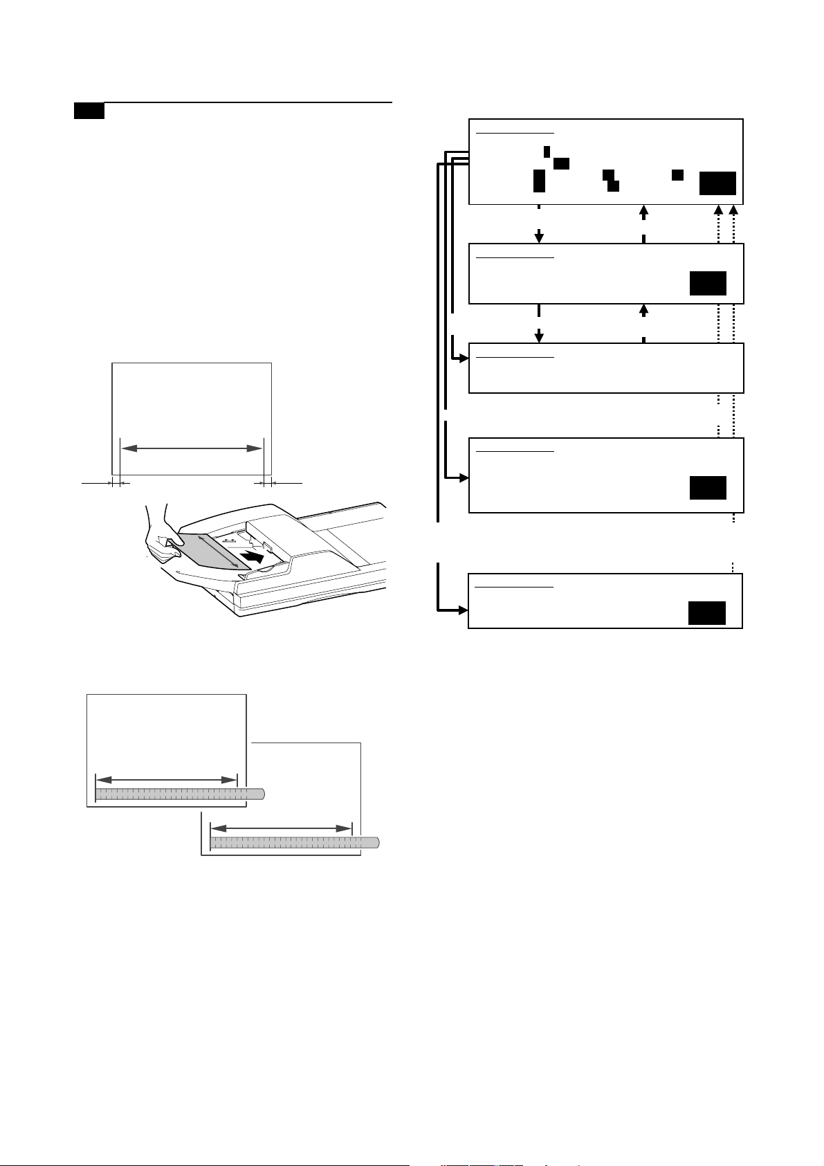
6-C Adjust the image magnification in the main
scanning direction in DSPF front-face mode
(CCD)
This adjustment is needed in the following situations:
* The CCD unit has been removed from the machine.
* The CCD unit has been replaced.
* Images are not correctly magnified in the main scanning direc-
tion.
* The MFP control PWB has been replaced.
* The EEPROM on the MFP control PWB has been replaced.
* The scan control PWB has been replaced.
* The EEPROM on the scan control PWB has been replaced.
* U2 trouble has occurred.
1) On the DSPF original tray, place such an original as illustrated
below.
5) Go through the modes specified in Simulation 48-1.
SIMULATION 48-1
MAGNIFICATION ADJUSTMENT. SELECT 0-7, AND PRESS START.
0.TRAY SELECT 1 1.PRINT START
2.MAGNIFICATION 100
3.CCD(MAIN) 50 4.CCD(SUB) 50 5.SPF(SUB) 50
6.CIS(MAIN) 50 7.SPF(MAIN) 50
Select other than0-2,
and press [START] key.
SIMULATION 48-1
MAGNIFICATION ADJUSTMENT. INPUT VALUE 0-99, AND PRESS
START.
4.CCD(SUB)
Select 1, and
press [START] key.
SIMULATION 48-1
MAGNIFICATION ADJUSTMENT. NOW COPYING.
Press [START] key. Press [SYSTEM SETTINGS] key,
Press [SYSTEM SETTINGS] key.
or terminate copying.
2
50
A4 size
10mm10mm
2) Make a normal copy on A4 paper.
3) Measure the lengths of the copied image and the original
image.
original
copy
10 50 100 150 200 250
10 50 100 150 200 250
Select 0, and press [START] key.
SIMULATION 48-1
MAGNIFICATION ADJUSTMENT. SELECT 1-16, AND PRESS START.
(FEED TRAY)
1.TRAY1 2.TRAY2 3.TRAY3 4.TRAY4
5.BPT 6.LCC
(ABOVE+10: DUPLEX MODE)
Select 2, and press
[START] key.
SIMULATION 48-1
MAGNIFICATION ADJUSTMENT.
(MAGNIFICATION)
INPUT 25-400(%)
Press [START] key, or press
[SYSTEM SETTINGS] key.
1
Press [START] key, or press
[SYSTEM SETTINGS] key.
100
6) Using the mumeric keypad, select the number that corresponds to the mode for which to make adjustments.
Select the adjustment item that is intended to adjust the image
magnification in the main scanning direction in DSPF frontface mode (CCD). (SPF (MAIN))
7) Press the Start key.
8) Adjust the image magnification factor by entering an appropriate value through the numeric keypad.
9) Press the P or Start key.
Pressing the Start key starts copy operation as well as applying the
adjustment value.
Repeat the above adjustments until an acceptable result is
obtained.
4) Determine the image magnification factor using the following
formula:
Image magnification factor (%) = Copy dimension/original
dimension x 100
Image magnification factor (%) = 99 / 100 x 100 = 99
If the image magnification factor is within the spec (100r0.8%),
no adjustment is required; otherwise, do the following steps.
MX-M700N ADJUSTMENTS 6 – 18
Page 70

6-D Adjust the image magnification in the main
scanning direction in DSPF back-face mode
(CIS)
This adjustment is needed in the following situations:
* The MFP control PWB has been replaced.
* The EEPROM on the MFP control PWB has been replaced.
* The scan control PWB has been replaced.
* The EEPROM on the scan control PWB has been replaced.
* U2 trouble has occurred.
* Images are not correctly magnified in the main scanning direc-
tion.
1) On the DSPF original tray, place such a duplex original as
illustrated below.
A4 size
5) Go through the modes specified in Simulation 48-1.
SIMULATION 48-1
MAGNIFICATION ADJUSTMENT. SELECT 0-7, AND PRESS START.
0.TRAY SELECT 1 1.PRINT START
2.MAGNIFICATION 100
3.CCD(MAIN) 50 4.CCD(SUB) 50 5.SPF(SUB) 50
6.CIS(MAIN) 50 7.SPF(MAIN) 50
Select other than0-2,
and press [START] key.
SIMULATION 48-1
MAGNIFICATION ADJUSTMENT. INPUT VALUE 0-99, AND PRESS
START.
4.CCD(SUB)
Select 1, and
press [START] key.
SIMULATION 48-1
MAGNIFICATION ADJUSTMENT. NOW COPYING.
Press [START] key. Press [SYSTEM SETTINGS] key,
Press [SYSTEM SETTINGS] key.
or terminate copying.
2
50
(both sides)
10mm10mm
2) Make a normal duplex copy on A4 paper.
3) Measure the lengths of the copied image (on the back side)
and the original image.
original
copy
10 50 100 150 200 250
10 50 100 150 200 250
4) Determine the image magnification factor using the following
formula:
Image magnification factor (%) = Copy dimension/original
dimension x 100
Image magnification factor (%) = 99 / 100 x 100 = 99
If the image magnification factor is within the spec (100r0.8%),
no adjustment is required; otherwise, do the following steps.
Select 0, and press [START] key.
SIMULATION 48-1
MAGNIFICATION ADJUSTMENT. SELECT 1-16, AND PRESS START.
(FEED TRAY)
1.TRAY1 2.TRAY2 3.TRAY3 4.TRAY4
5.BPT 6.LCC
(ABOVE+10: DUPLEX MODE)
Select 2, and press
[START] key.
SIMULATION 48-1
MAGNIFICATION ADJUSTMENT.
(MAGNIFICATION)
INPUT 25-400(%)
Press [START] key, or press
[SYSTEM SETTINGS] key.
1
Press [START] key, or press
[SYSTEM SETTINGS] key.
100
6) Select the number that corresponds to the adjustment item
CIS (MAIN) using the numeric keypad.
This adjustment item is intended to adjust the image magnification in the main scanning direction in DSPF back-face mode
(CIS). (CIS (MAIN))
7) Press the Start key.
8) Adjust the image magnification factor by entering an appropriate value through the numeric keypad.
9) Press the P or Start key. Pressing the Start key starts copy
operation as well as applying the adjustment value.
Repeat the above adjustments until an acceptable result is
obtained.
MX-M700N ADJUSTMENTS 6 – 19
Page 71

6-E Adjust the image magnification in the sub-
scanning direction in DSPF mode
This adjustment is needed in the following situations:
* Images are not correctly magnified in the sub-scanning direction.
* The MFP control PWB has been replaced.
* The EEPROM on the MFP control PWB has been replaced.
* The scan control PWB has been replaced.
* The EEPROM on the scan control PWB has been replaced.
* U2 trouble has occurred.
1) On the DSPF original tray, place such an original as illustrated
below.
10mm
A4 size
5) Go through the modes specified in Simulation 48-1.
SIMULATION 48-1
MAGNIFICATION ADJUSTMENT. SELECT 0-7, AND PRESS START.
0.TRAY SELECT 1 1.PRINT START
2.MAGNIFICATION 100
3.CCD(MAIN) 50 4.CCD(SUB) 50 5.SPF(SUB) 50
6.CIS(MAIN) 50 7.SPF(MAIN) 50
Select other than0-2,
and press [START] key.
SIMULATION 48-1
MAGNIFICATION ADJUSTMENT. INPUT VALUE 0-99, AND PRESS
START.
4.CCD(SUB)
Select 1, and
press [START] key.
SIMULATION 48-1
MAGNIFICATION ADJUSTMENT. NOW COPYING.
Press [START] key. Press [SYSTEM SETTINGS] key,
Press [SYSTEM SETTINGS] key.
or terminate copying.
2
50
10mm
2) Make a normal copy on A4 paper.
3) Measure the lengths of the copied image and the original
image.
10 50 100 150 200
10 50 100 150 200
original
copy
4) Determine the image magnification factor using the following
formula:
Image magnification factor (%) = Copy dimension/original
dimension x 100
Image magnification factor (%) = 99 / 100 x 100 = 99
If the image magnification factor is within the spec (100r0.8%),
no adjustment is required; otherwise, do the following steps.
Select 0, and press [START] key.
SIMULATION 48-1
MAGNIFICATION ADJUSTMENT. SELECT 1-16, AND PRESS START.
(FEED TRAY)
1.TRAY1 2.TRAY2 3.TRAY3 4.TRAY4
5.BPT 6.LCC
(ABOVE+10: DUPLEX MODE)
Select 2, and press
[START] key.
SIMULATION 48-1
MAGNIFICATION ADJUSTMENT.
(MAGNIFICATION)
INPUT 25-400(%)
Press [START] key, or press
[SYSTEM SETTINGS] key.
1
Press [START] key, or press
[SYSTEM SETTINGS] key.
100
6) Select the number that corresponds to the adjustment item
SPF (SUB) using the numeric keypad.
This adjustment items is intended to adjust the image magnification in the sub-scanning direction in DSPF mode.
(SPF (SUB))
7) Press the Start key.
8) Adjust the image magnification factor by entering an appropriate value through the numeric keypad.
9) Press the P or Start key.
Pressing the Start key starts copy operation as well as applying the adjustment value. Repeat the above adjustments until
an acceptable result is obtained.
* After adjusting the image magnification in the sub-scanning
direction through Simulation 48-1, do the following steps if
making a copy at a different magnification factor fails to produce a correctly scaled copy.
1) Go through the modes specified in Simulation 48-5.
SIMULATION 48-5
MOTOR SPEED ADJUSTMENT. SELECT 0-4, AND PRESS START.
0.MIR(220) 50 1.MIR(110) 50
2.SPF(360) 50 3.SPF(220) 50
4.SPF(110) 50
0
Select 0 - 5, and
press [START] key.
MX-M700N ADJUSTMENTS 6 – 20
Press [START] key, or press
[SYSTEM SETTINGS] key.
Page 72
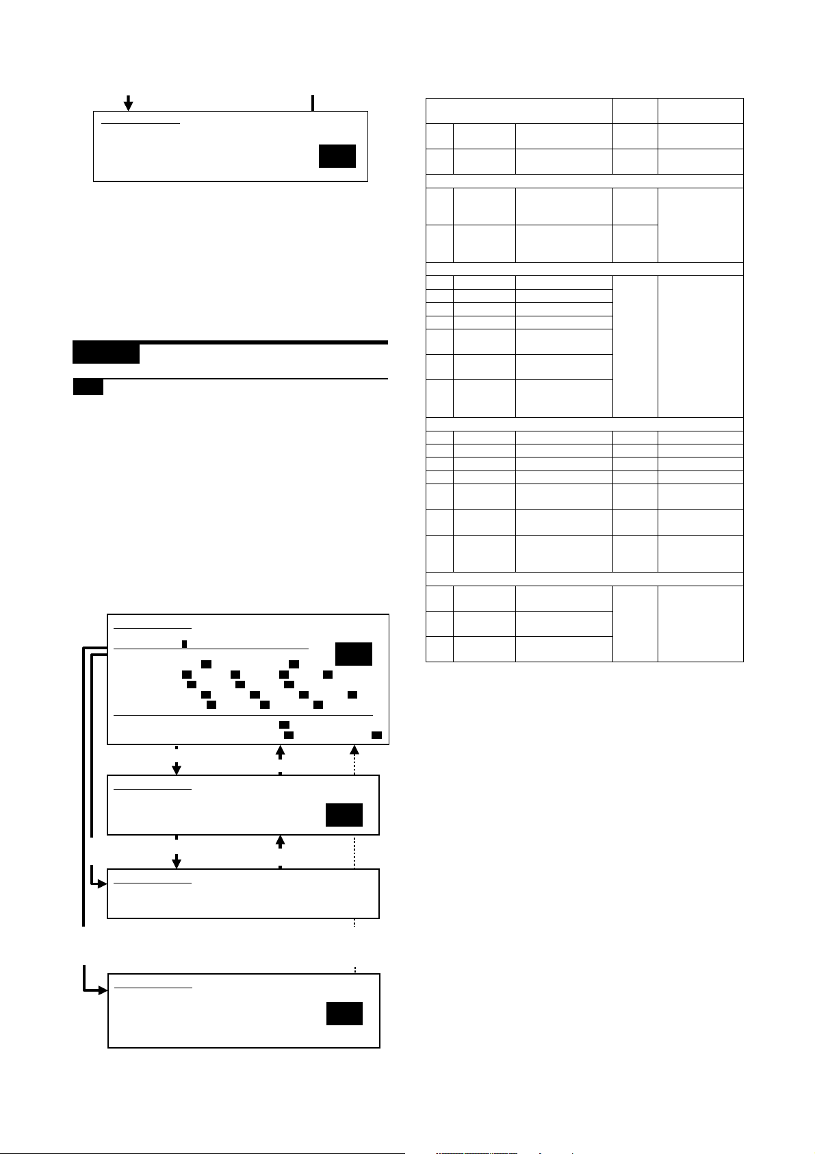
SIMULATION 48-5
SCAN MOTOR SPEED ADJUSTMENT. INPUT VALUE 0-99, AND
PRESS START.
0.MIR(220)
50
2) Using the numeric keypad, select the number that corresponds
to the mode for which to make adjustments.
3) Press the Start key.
4) Enter the copy adjustment value using the numeric keypad.
Make adjustments by changing the adjustment value for high
revolution mode if the copy magnification is not correct for
microcopies; or the adjustment value for low revolution mode if
the copy magnification is not correct for blowbacks.
5) Press the Start key. This applies the adjustment value.
ADJ 7 Adjusting the image off-center
7-A Adjust the print image off-center
(print engine section)
This adjustment is needed in the following situations:
* The paper feed section has been disassembled.
* The MFP control PWB has been replaced.
* The EEPROM on the MFP control PWB has been replaced.
* The scan control PWB has been replaced.
* The EEPROM on the scan control PWB has been replaced.
* The scanner (reading) section has been disassembled.
* The scanner (reading) unit has been replaced.
* The LSU has been replaced.
* U2 trouble has occurred.
(Print image off-center adjustment)
1) Go through the modes specified in Simulation 50-5.
SIMULATION 50-5
LEAD EDGE ADJUSTMENT. SELECT 0-20, AND PRESS START.
0.TRAY SELECT 1 1.PRINT START
(ADJUSTMENT DATA)
LEAD EDGE: 2.RRCB 50 20.SIDE2 ADJ. 50
RESIST: 3.T1 50 4.T2 50 5.T3 50 6.T4 50
OFF CENTER: 10.T1 50 11.T2 50 12.T3 50 13.T4 50
(VOID SETTING) 17.LEAD_EDGE(DENA) 50
Select other than0-1,and
press [START] key.
SIMULATION 50-5
LEAD EDGE ADJUSTMENT. INPUT VALUE 0-99, AND PRESS
START.
2.RRCB
7.BPT 50 8.LCC 50 9.ADU 50
14.BPT 50 15.LCC 50 16.ADU 50
18.TRAIL_EDGE(DENB) 30 19.FRONT/REAR 30
Press [SYSTEM SETTINGS] key.
2
50
Item
0TRAY
SELECT
1 PRINT
START
(Lead edge adjustment value)
2 RRCB Resist roller clutch
SIDE2-ADJ Offset (adjustment)
(Resist adjustment value)
3 TRAY1 Tray 1 adjustment 0 – 99 50
4 TRAY2 Tray 2 adjustment
5 TRAY3 Tray 3 adjustment
6 TRAY4 Tray 4 adjustment
7 BPT Manual feed tray
8 LCC Side LCC
9 ADU Adjustment when
(Off-center set value) Self print
10 TRAY 1 Tray 1 adjustment – –
11 TRAY 2 Tray 2 adjustment – –
12 TRAY 3 Tray 3 adjustment – –
13 TRAY 4 Tray 4 adjustment – –
14 BPT Manual feed tray
15 LCC Side LCC
16 ADU Adjustment when
(Void set value)
7 LEAD_EDG
E(DENA)
8TRAIL_ED
GE(DENB)
9 FRONT/
REAR
Paper feed tray
selection
Print start (Default) – –
ON timing
adjustment value
of the RRCB setting
during rear print.
adjustment
adjustment
paper is fed again
from ADU
adjustment
adjustment
paper is fed again
from ADU
Lead edge void set
value
Rear edge void
adjustment value
Front/Rear void
adjustment value
Setting
range
1 – 6 –
0 – 99 50
1 – 99
––
––
––
0 – 99 35
Default
2) Enter the number that corresponds to the paper feed tray that
needs adjustments. (Choose from numbers 10 to 16.)
3) Press the Start key.
4) Press the Start key.
A self-print pattern image is printed.
Check the off-center of the printed self-print pattern image.
If so, no adjustment is required.
Measure the void area dimensions in the front and rear frame
directions, and make sure that the difference between the two
dimensions is within 0r1.5 mm.
Select 1, and
press [START] key.
Select 0, and press
[START] key.
Press [START] key.
SIMULATION 50-5
LEAD EDGE ADJUSTMENT. NOW PRINTING.
SIMULATION 50-5
LEAD EDGE ADJUSTMENT. SELECT 1-16, AND PRESS START.
(FEED TRAY)
1.TRAY1 2.TRAY2 3.TRAY3 4.TRAY4
5.BPT 6.LCC
(ABOVE+10: DUPLEX MODE)
Press [SYSTEM SETTINGS]
key, or terminate copying.
Press [START] key, or press
[SYSTEM SETTINGS] key.
1
MX-M700N ADJUSTMENTS 6 – 21
Page 73

SIMULATION 50-12
100
SIMULATION 50-12
ORIGINAL OFF-CENTER ADJUSTMENT.
(MAGNIFICATION)
INPUT 25-400(%)
ORIGINAL OFF-CENTER ADJUSTMENT. SELECT 0-9, AND PRESS
START.
0.TRAY SELECT 1 1.COPY START
2.MAGNIFICATION 100
(ADJUSTMENT DATA)
3.PLATEN 50 4.SPF SIDE1 50 5.SPF SIDE2 50
2
If the above requirement is not met, do the following steps.
5) Using the numeric keypad, change the adjustment value in
steps of 0.1 mm. A larger setting shifts the printed image
toward the front side.
6) Press the P or Start key. Pressing the Start key starts print
operation as well as applying the adjustment value. Check the
off-center of the printed self-print pattern image.
Repeat steps 5 to 6 until an acceptable result is obtained.
Select other than0-2,and
press [START] key.
SIMULATION 50-12
ORIGINAL OFF-CENTER ADJUSTMENT. INPUT VALUE 0-99, AND
PRESS START.
3.PLATEN
Select 1, and
press [START]
key.1
Select 0, and press [START] key.
Select 2, and press
[START] key.
Press [START] key.
SIMULATION 50-12
ORIGINAL OFF-CENTER ADJUSTMENT. NOW COPYING.
SIMULATION 50-12
ORIGINAL OFF-CENTER ADJUSTMENT. SELECT 1-16, AND PRESS
START.
(FEED TRAY)
1.TRAY1 2.TRAY2 3.TRAY3 4.TRAY4
5.BPT 6.LCC
(ABOVE+10: DUPLEX MODE)
Press [SYSTEM SETTINGS] key.
Press [SYSTEM SETTINGS] key,
or terminate copying.
Press [START] key,
or press [SYSTEM SETTINGS] key.
Press [START] key, or press
[SYSTEM SETTINGS] key.
50
Increasing the adjustment value by 0.1 mm/step causes position of the printed image toward the front side.
1
7-B Adjust the scanned image off-center in
original table mode (scan section)
This adjustment is needed in the following situations:
* The MFP control PWB has been replaced.
* The EEPROM on the MFP control PWB has been replaced.
* The scan control PWB has been replaced.
* The EEPROM on the scan control PWB has been replaced.
* The scanner (reading) section has been disassembled.
* The scanner (reading) unit has been replaced.
* U2 trouble has occurred.
(Adjustment mode selection)
1) Go through the modes specified in Simulation 50-12.
Item
0TRAY
SELECT
1 COPY
START
2 MAGNIFICA
TION
(Off-center adjustment value)
3 PLATEN OC mode adjustment 0 – 99 50
4 SPF SIDE1 SPF front surface
5 SPF SIDE2 SPF back surface
Paper feed tray selection 1 – 5 –
Copy START (Default) – –
Print magnification ratio 25 –
adjustment
adjustment
Setting
range
400%
Default
100
2) Using the numeric keypad, select the adjustment item
PLATEN, which is intended to adjust the off-center in original
table mode.
3) Press the Start key.
MX-M700N ADJUSTMENTS 6 – 22
Page 74

(Scan off-center adjustment)
1) Place an original on the original table.
2) Press the Start key.
Check the off-center of the printed image.
If the off-center is 0r4.0 mm, no adjustment is required.
original copy
SIMULATION 50-12
ORIGINAL OFF-CENTER ADJUSTMENT. SELECT 0-9, AND PRESS
START.
0.TRAY SELECT 1 1.COPY START
2.MAGNIFICATION 100
(ADJUSTMENT DATA)
3.PLATEN 50 4.SPF SIDE1 50 5.SPF SIDE2 50
2
a
b
If the above requirement is not met, do the following steps.
3) Using the numeric keypad, change the adjustment value in
steps of 0.1 mm to adjust the scan image off-center. A larger
setting shifts the printed image toward the front side.
4) Press the P or Start key.
Pressing the Start key starts copy operation as well as applying the adjustment value.
5) Check the off-center of the printed image.
Repeat the above adjustments until an acceptable result is
obtained.
7-C Adjust the scanned image off-center in
DSPF front-face mode (scan section)
This adjustment is needed in the following situations:
* The MFP control PWB has been replaced.
* The EEPROM on the MFP control PWB has been replaced.
* The scan control PWB has been replaced.
* The EEPROM on the scan control PWB has been replaced.
* The scanner (reading) section has been disassembled.
* The scanner (reading) unit has been replaced.
* U2 trouble has occurred.
* The DSPF section has been disassembled.
* The DSPF unit has been replaced.
(Adjustment mode selection)
1) Go through the modes specified in Simulation 50-12.
Select other than0-2,and
press [START] key.
SIMULATION 50-12
ORIGINAL OFF-CENTER ADJUSTMENT. INPUT VALUE 0-99, AND
PRESS START.
3.PLATEN
Select 1, and
press [START]
key.1
Select 0, and press [START] key.
Select 2, and press
[START] key.
Press [START] key.
SIMULATION 50-12
ORIGINAL OFF-CENTER ADJUSTMENT. NOW COPYING.
SIMULATION 50-12
ORIGINAL OFF-CENTER ADJUSTMENT. SELECT 1-16, AND PRESS
START.
(FEED TRAY)
1.TRAY1 2.TRAY2 3.TRAY3 4.TRAY4
5.BPT 6.LCC
(ABOVE+10: DUPLEX MODE)
SIMULATION 50-12
ORIGINAL OFF-CENTER ADJUSTMENT.
(MAGNIFICATION)
INPUT 25-400(%)
Press [SYSTEM SETTINGS] key.
Press [SYSTEM SETTINGS] key,
or terminate copying.
Press [START] key,
or press [SYSTEM SETTINGS] key.
Press [START] key, or press
[SYSTEM SETTINGS] key.
100
50
1
Increasing the adjustment value by 0.1 mm/step causes position of the printed image toward the front side.
Item
0TRAY
SELECT
1COPY
START
2MAGNIFI
CATION
(Off-center adjustment value)
3 PLATEN OC mode adjustment 0 – 99 50
4 SPF SIDE1 SPF front surface adjustment
5 SPF SIDE2 SPF back surface adjustment
Paper feed tray selection 1 – 5 –
Copy START (Default) – –
Print magnification ratio 25 –
Setting
range
400%
Default
100
2) Using the numeric keypad, select the adjustment item DSPF
SIDE1, which is intended to adjust the off-center in DSPF
front-face mode.
3) Press the Start key.
MX-M700N ADJUSTMENTS 6 – 23
Page 75

(Scan off-center adjustment)
50
1
2
SIMULATION 50-12
ORIGINAL OFF-CENTER ADJUSTMENT. SELECT 0-9, AND PRESS
START.
0.TRAY SELECT 1 1.COPY START
2.MAGNIFICATION 100
(ADJUSTMENT DATA)
3.PLATEN 50 4.SPF SIDE1 50 5.SPF SIDE2 50
SIMULATION 50-12
ORIGINAL OFF-CENTER ADJUSTMENT. NOW COPYING.
SIMULATION 50-12
ORIGINAL OFF-CENTER ADJUSTMENT. INPUT VALUE 0-99, AND
PRESS START.
3.PLATEN
SIMULATION 50-12
ORIGINAL OFF-CENTER ADJUSTMENT. SELECT 1-16, AND PRESS
START.
(FEED TRAY)
1.TRAY1 2.TRAY2 3.TRAY3 4.TRAY4
5.BPT 6.LCC
(ABOVE+10: DUPLEX MODE)
Select other than0-2,and
press [START] key.
Press [SYSTEM SETTINGS] key.
Select 1, and
press [START]
key.1
Press [START] key.
Press [SYSTEM SETTINGS] key,
or terminate copying.
Select 0, and press [START] key.
Press [START] key,
or press [SYSTEM SETTINGS] key.
100
SIMULATION 50-12
ORIGINAL OFF-CENTER ADJUSTMENT.
(MAGNIFICATION)
INPUT 25-400(%)
1) Place an original on the DSPF original tray.
2) Press the Start key. Check the off-center of the printed image.
If the off-center is 0r2.5 mm, no adjustment is required.
original copy
a
b
If the above requirement is not met, do the following steps.
3) Using the numeric keypad, change the adjustment value in
steps of 0.1 mm to adjust the scan image off-center. A larger
setting shifts the printed image toward the rear side.
4) Press the P or Start key. Pressing the Start key starts copy
operation as well as applying the adjustment value.
5) Check the off-center of the printed image.
Repeat the above adjustments until an acceptable result is
obtained.
(Adjustment mode selection)
1) Go through the modes specified in Simulation 50-12.
Select 2, and press
[START] key.
Press [START] key, or
press [SYSTEM
SETTINGS] key.
7-D Adjust the scanned image off-center in
DSPF back-face mode (scan section)
This adjustment is needed in the following situations:
* The MFP control PWB has been replaced.
* The EEPROM on the MFP control PWB has been replaced.
* The scan control PWB has been replaced.
* The EEPROM on the scan control PWB has been replaced.
* The scanner (reading) section has been disassembled.
* The scanner (reading) unit has been replaced.
* U2 trouble has occurred.
* The DSPF section has been disassembled.
* The DSPF unit has been replaced.
Increasing the adjustment value by 0.1 mm/step causes position of the printed image toward the front side.
Item
0TRAY
SELECT
1COPY
START
2MAGNIFI
CATION
(Off-center adjustment value)
3 PLATEN OC mode adjustment 0 – 99 50
4 SPF SIDE1 SPF front surface adjustment
5 SPF SIDE2 SPF back surface adjustment
Paper feed tray selection 1 – 5 –
Copy START (Default) – –
Print magnification ratio 25 –
Setting
range
400%
Default
100
2) Using the numeric keypad, select the adjustment item DSPF
SIDE2, which is intended to adjust the off-center in DSPF
back-face mode.
3) Press the Start key.
MX-M700N ADJUSTMENTS 6 – 24
Page 76

(Scan off-center adjustment)
1) Place an original on the DSPF original tray.
2) Press the Start key.
Since the front side and back side images are copied onto separate sheets, check the off-center of the back side image.
If the off-center is 0r2.7 mm, no adjustment is required.
original copy
a
Papar lead edge Papar tail edge
No Image
Void (RV)
LIL = 1.5 mm
10 20
Image loss (LIL)
LV = 3.5 mm
TV = 3.5 mm
= 7.0 mm
FV+RV
No Image
Void (TV)
b
If the above requirement is not met, do the following steps.
3) Using the numeric keypad, change the adjustment value in
steps of 0.1 mm to adjust the scan image off-center. A larger
setting shifts the printed image toward the rear side.
4) Press the P or Start key.
Pressing the Start key starts copy operation as well as applying the adjustment value.
5) Check the off-center of the printed image.
Repeat the above adjustments until an acceptable result is
obtained.
ADJ 8 Adjusting the image position,
image loss, and void area
8-A Adjust copied image loss/void area in
original table mode
This adjustment is needed in the following situations:
* The paper feed section has been disassembled.
* The MFP control PWB has been replaced.
* The EEPROM on the MFP control PWB has been replaced.
* The scan control PWB has been replaced.
* The EEPROM on the scan control PWB has been replaced.
* The scanner (reading) section has been disassembled.
* The scanner (reading) unit has been replaced.
* The LSU has been replaced.
* U2 trouble has occurred.
No Image
Void (LV)
No Image
Void (FV)
1) Go through the modes specified in Simulation 50-1.
SIMULATION 50-1
LEAD EDGE ADJUSTMENT. SELECT 0-9, AND PRESS START.
0.TRAY SELECT 1 1.COPY START
2.MAGNIFICATION 100
(ADJUSTMENT DATA) 3.RRCA 50 4.RRCB 50 10.SIDE2 ADJ. 50
(IMAGE LOSS SETTING) 5.LEAD 15 6.SIDE 20
(VOID SETTING) 7.LEAD_EDGE(DENA) 50
Select other than0-2,and
press [START] key.
SIMULATION 50-1
LEAD EDGE ADJUSTMENT. INPUT VALUE 0-99, AND PRESS
START.
3.RRCA
Select 1, and
press [START] key.
SIMULATION 50-1
LEAD EDGE ADJUSTMENT. NOW COPYING.
Select 0, and press [START] key.
SIMULATION 50-1
LEAD EDGE ADJUSTMENT. SELECT 1-6, AND PRESS START.
(FEED TRAY)
1.TRAY1 2.TRAY2 3.TRAY3 4.TRAY4
5.BPT 6.LCC
Select 2, and press
[START] key.
SIMULATION 50-1
LEAD EDGE ADJUSTMENT.
(MAGNIFICATION)
INPUT 25-400(%)
Item Content
0 TRAY SELECT Paper feed tray selection 1 – 6 –
1 COPY START Copy START (Default) – –
2 MAGNIFICATIONPrint magnification ratio 25 –
(Lead edge adjustment value)
3 RRCA Document scan start position
4 RRCB Resist roller clutch ON timing
8.TRAIL_EDGE(DENB) 30 9.FRONT/REAR 30
Press [SYSTEM SETTINGS] key.
Press [START] key.
adjustment value
adjustment value
Press [SYSTEM SETTING] key,
or terminate copying.
Press [START] key,
or press [SYSTEM SETTINGS] key.
Press [START] key, or press
[SYSTEM SETTINGS] key.
100
Setting
range
400%
0 – 99 50
2
50
1
Default
–
MX-M700N ADJUSTMENTS 6 – 25
Page 77

Item Content
SIDE2-ADJ Offset (adjustment) of the
(Image loss set value)
5 LEAD LEAD Lead edge image loss
6 SIDE Side image loss set 20
(Void set value)
7 LEAD_EDGE
(DENA)
8 TRAIL_EDGE
(DENB)
9 FRONT/REAR Front/Rear void adjustment
RRCB setting during rear print.
set value
Lead edge void set value 0 – 99 35
Rear edge void adjustment
value
value
Setting
Default
range
1 – 99 50
0 – 99 15
(Leading edge image loss/void area adjustment)
1) Set the adjustment values for leading edge image loss and
leading edge void as follows:
(Standard setting)
Leading edge image loss: 1.5 mm (LEAD:15)
Leading edge void: 3.5mm (DENA:35)
* Set the adjustment value for (LEAD) to 15 by entering "15"
into the (LEAD) adjustment value field and then pressing the
P key.
* Set the adjustment value for (DENA) to 35 by entering "35"
into the (DENA) adjustment value field and then pressing the
P key.
2) Make a copy at 100% magnification by entering "100" into the
(MAGNIFICATION) field and then pressing the Start key, and
check the leading edge void area and image loss.
Papar lead edge
No Image
10 20
Image loss (LIL)
Void (LV)
Image area
LIL = 1.5 mm
LV = 3.5 mm
(Trailing edge void area adjustment)
1) Make a copy at 100% magnification by entering "100" into the
(MAGNIFICATION) field and then pressing the Start key, and
check the trailing edge void area.
(Standard setting) Trailing edge void area: 3.5 mm
Papar tail edge
TV = 3.5 mm
Void (TV)
No Image
If the trailing edge void area is not at an acceptable level, do
the following steps.
2) Repeat the process of changing the (TRAIL EDGE) adjustment value and then pressing the Start key until attaining an
acceptable level.
Repeat the above adjustments until acceptable results are
obtained.
(Front/rear frame direction image loss adjustment)
1) Set the (SIDE) adjustment value to 20 by entering "20" into the
(SIDE) adjustment value field and then pressing the P key.
Note that changing this adjustment value shifts the image position in the front/rear frame direction.
(Front/rear frame direction void area)
1) Make a copy at 100% magnification by entering "100" into the
(MAGNIFICATION) field and then pressing the Start key, and
check the front/rear frame direction void area.
(Standard settings)
Front frame side void area = 3.5 mm, rear frame side void area
= 3.5 mm, sum of front/rear frame direction void area = 7.0
mm.
If the leading edge image loss and void area are not at acceptable levels, do the following steps.
* If the leading edge void area is not 3.5 mm:
Repeat the process of changing the (RRCB) adjustment
value and then pressing the Start key until attaining an
acceptable level.
(The change according to the one step of the adjustment
value is 0.1mm.)
* If the leading edge image loss is not 1.5mm:
Repeat the process of changing the (RRCA) adjustment
value, in steps of 0.1 mm, and then pressing the Start key
until attaining an acceptable level.
(The adjustment value should be changed in steps of
0.2mm.)
Repeat the above adjustments until acceptable results are
obtained.
MX-M700N ADJUSTMENTS 6 – 26
No Image
Void (RV)
= 7.0 mm
FV+RV
No Image
Void (FV)
If the front/rear frame direction void area is not at an acceptable level, do the following steps.
2) Repeat the process of changing the (FRONT/REAR) adjustment value and then pressing the Start key until attaining an
acceptable level.
Repeat the above adjustments until acceptable results are
obtained.
NOTE: If the front and rear frame side void areas are not equal,
adjust the image off-center position using Simulation 50-5.
Page 78

8-B Adjust the original scan start position
(adjust the scanner read position in DSPFmode front face scan)
This adjustment is needed in the following situations:
* The MFP control PWB has been replaced.
* The EEPROM on the MFP control PWB has been replaced.
* The scan control PWB has been replaced.
* The EEPROM on the scan control PWB has been replaced.
* The scanner (reading) section has been disassembled.
* The scanner (reading) unit has been replaced.
* U2 trouble has occurred.
* The DSPF section has been disassembled.
* The DSPF unit has been replaced.
This adjustment is intended to adjust the scanner read position in
DSPF mode front face scan.
An incorrect adjustment would deviate the scanner stop position
from the required position, thus possibly causing a shadow of the
original table to appear at the leading edge of an image generated
by DSPF (front-face) mode scan.
1) Make a copy in DSPF (front-face) mode, and make sure that
the printed image at the leading edge of the copied image is
free from shadows.
8-C Adjust the copied image loss/void area in
DSPF mode
This adjustment is needed in the following situations:
* The MFP control PWB has been replaced.
* The EEPROM on the MFP control PWB has been replaced.
* The scan control PWB has been replaced.
* The EEPROM on the scan control PWB has been replaced.
* The scanner (reading) section has been disassembled.
* The scanner (reading) unit has been replaced.
* U2 trouble has occurred.
* The DSPF section has been disassembled.
* The DSPF unit has been replaced.
Papar lead edge Papar tail edge
No Image
Void (RV)
LIL = 1.5 mm
10 20
Image loss (LIL)
LV = 3.5 mm
TV = 3.5 mm
= 7.0 mm
FV+RV
No Image
Void (TV)
Papar lead edge
Image area
Shadow image of DSPF
If the printed image at the leading edge of the copied image
contains a shadow of the original table, then do the following
steps.
2) Go through the modes specified in Simulation 53-8.
SIMULATION 53-8
SPF SCANNING POSITION ADJUSTMENT. PRESS START.
2.MANUAL 25
Select 2, and press
[START] key.
SIMULATION 53-8
SPF SCANNING POSITION ADJUSTMENT. INPUT VALUE 1-70, AND
PRESS START.
2.MANUAL
Press [START] key, or press
[SYSTEM SETTINGS] key.
25
3) Enter the adjustment value and press the Start key.
Repeat the above adjustments until an acceptable result is
obtained.
No Image
Void (LV)
No Image
Void (FV)
1) Go through the modes specified in Simulation 50-6.
SIMULATION 50-6
LEAD EDGE ADJUSTMENT(SPF). SELECT 0-10, AND PRESS
START.
0.TRAY SELECT 1 1.COPY START
2.MAGNIFICATION 100
(ADJUSTMENT DATA)3.SIDE1 50 4.SIDE2 50
(IMAGE LOSS SETTING)
SIDE1: 5.LEAD_EDGE 15 6.FRONT/REAR 20 7.TRAIL_EDGE 0
SIDE2: 8.LEAD_EDGE 15 9.FRONT/REAR 20 10.TRAIL_EDGE 0
Select other than0-2,and
press [START] key.
SIMULATION 50-6
LEAD EDGE ADJUSTMENT(SPF). INPUT VALUE 0-99, AND PRESS
START.
3.SIDE1
Select 1, and
press [START] key.
Select 0, and press [START] key.
Press [START] key.
SIMULATION 50-6
LEAD EDGE ADJUSTMENT(SPF). NOW COPYING.
SIMULATION 50-6
LEAD EDGE ADJUSTMENT(SPF). SELECT 1-16, AND PRESS
START.
(FEED TRAY)
1.TRAY1 2.TRAY2 3.TRAY3 4.TRAY4
5.BPT 6.LCC
(ABOVE+10: DUPLEX MODE)
Press [SYSTEM SETTING] key.
Press [SYSTEM SETTINGS]
key, or terminate copying.
Press [START] key or press
[SYSTEM SETTINGS] key.
2
50
1
Select 2, and press
[START] key.
MX-M700N ADJUSTMENTS 6 – 27
Press [START] key, or press
[SYSTEM SETTINGS] key.
Page 79

SIMULATION 50-6
LEAD EDGE ADJUSTMENT(SPF).
(MAGNIFICATION)
INPUT 25-200(%)
Item
0TRAY
SELECT
1 COPY
START
2MAGNIFI
CATION
(Lead edge adjustment value)
3 SIDE1 Front surface document
4 SIDE2 Back surface document
(Image loss set value: SIDE 1)
5 LEAD
_EDGE
6FRONT
_REAR
7TRAIL
_EDGE
(Image loss set value: SIDE 2)
8 LEAD
_EDGE
9FRONT
/REAR
10 TRAIL
_EDGE
Paper feed tray selection 1 – 6 —
Copy START (Default) — —
Print magnification ratio 25 –
scan start position
adjustment value
scan start position
adjustment value
Front surface lead edge
image loss set value
Front surface side edge
image loss set value
Front surface rear edge
image loss set value
Back surface lead edge
image loss set value
Back surface side edge
image loss set value
Back surface rear edge
image loss set value
100
Setting
range
200%
0 – 99 50
0 – 99 15
0 – 20 0
0 – 99 15
0 – 20 0
Default
—
20
20
(Leading edge image loss adjustment)
1) Set the adjustment values for leading edge image loss for the
front and back sides as follows:
(Standard setting)
5 LEAD_EDGE: 15
8 LEAD_EDGE: 15
* Set the adjustment value for "5 LEAD_EDGE" and "8
LEAD_EDGE" to 15 by entering "15" into the (LEAD EDGE)
adjustment value field and then pressing the P key.
2) In DSPF mode, make a duplex copy at 100% magnification,
and make sure that the leading edge image loss is 1.5 mm for
both the front and back sides. (Select duplex mode from the
paper selection mode as described in Simulation 50-6). (Enter
"100" into the (MAGNIFICATION) field, and then press the
start key).
Papar lead edge
3) Repeat the process of changing the (SIDE1 & SIDE2) adjustment values and then pressing the Start key until attaining an
acceptable level.
SIDE1: Adjustment value for the position at which to read the
leading edge of the original in DSPF front side mode.
SIDE2: Adjustment value for the position at which to read the
leading edge of the original in DSPF back side mode.
(The change according to the one step of the adjustment value
is 0.1mm.)
(The timing in which to start reading the image should be
determined based on the timing in which detector SPPD4
detects the leading edge of the original.)
Repeat steps 2 to 3 until an acceptable result is obtained.
(Trailing edge image loss adjustment)
1) Select duplex mode from paper selection mode as described
in Simulation 50-6, enter "100" into the (MAGNIFICATION)
field, and then press the Start key to make a duplex copy at
100% magnification in DSPF mode, and make sure that the
trailing edge image loss is 1.5 mm for both front and back
sides.
Papar trail edge
TIL = 1.5 mm
Image area
TV = 3.5 mm
Image loss (TIL)
Void (TV)
No Image
If an acceptable result is not obtained, do the following steps.
2) Repeat the process of changing the (TRAIL EDGE) adjustment value and then pressing the Start key until attaining an
acceptable level.
Repeat the above adjustments until an acceptable result is
obtained.
(Front/rear frame direction image loss adjustment)
Set the (FRONT/REAR) adjustment value to 20 by entering "20"
into the (FRONT/REAR) adjustment value field and then pressing.
Note that changing this adjustment value shifts the image position
in the front/rear frame direction.
8-D Adjust the image loss in scanner mode
1) Go through the modes specified in Simulation 50-27.
TIL = 1.5 mm
TV = 3.5 mm
Image area
Image loss (TIL)
Void (TV)
No Image
If an acceptable result is not obtained, do the following steps.
MX-M700N ADJUSTMENTS 6 – 28
SIMULATION 50-27
ORIGINAL IMAGE LOSS SETTING(FAX/SCN). SELECT 1-18, AND
PRESS START.
[FAX]
1.OC(LEAD_EDGE) 0 2.OC(FRONT/REAR) 0 3.OC(TRAIL_EDGE) 0
4.SPF(LEAD_EDGE) 0 5.SPF(FRONT/REAR) 0 6.SPF(TRAIL_EDGE) 0
7.CIS(LEAD_EDGE) 0 8.CIS(FRONT/REAR) 0 9.CIS(TRAIL_EDGE) 0
[SCN]
10.OC(LEAD_EDGE) 0 11.OC(FRONT/REAR) 0 12.OC(TRAIL_EDGE) 0
13.SPF(LEAD_EDGE) 0 14.SPF(FRONT/REAR) 0 15.SPF(TRAIL_EDGE) 0
16.CIS(LEAD_EDGE) 0 17.CIS(FRONT/REAR) 0 18.CIS(TRAIL_EDGE) 0
Press [START] key. Press [SYSTEM SETTINGS] key.
1
Page 80

SIMULATION 50-27
ORIGINAL IMAGE LOSS SETTING(FAX/SCN). INPUT 0-10, AND
PRESS START.
1.OC(LEAD_EDGE)
Item
FAX send
1 OC (LEAD_EDGE) OC lead edge 0 – 10
2 OC (FRONT/REAR) OC side
3 OC (TRAIL_EDGE) OC rear edge
4 SPF (LEAD_EDGE) SPF lead edge
5 SPF (FRONT/REAR) SPF side
6 SPF (TRAIL_EDGE) SPF rear edge
7 CIS (LEAD_EDGE) CIS lead edge
8 CIS (FRONT/REAR) CIS side
9 CIS (TRAIL_EDGE) CIS rear edge
Scanner mode
10 OC (LEAD_EDGE) OC lead edge 0 – 10
11 OC (FRONT/REAR) OC side
12 OC (TRAIL_EDGE) OC rear edge
13 SPF (LEAD_EDGE) SPF lead edge
14 SPF (FRONT/REAR) SPF side
15 SPF (TRAIL_EDGE) SPF rear edge
16 CIS (LEAD_EDGE) CIS lead edge
17 CIS (FRONT/REAR) CIS side
18 CIS (TRAIL_EDGE) CIS rear edge
0
Setting
range
(Unit 1mm)3(3mm)
(Unit 1mm)0 (0mm)
Default
2) Using the numeric keypad, enter the number that corresponds
to the scanner mode adjustment item.
3) Press the Start key.
4) Enter the adjustment value using the numeric keypad.
5) Press the Start key (The adjustment value should be changed
in steps of 1.0mm.)
Scanned images must be visually checked for image loss.
NOTE: Make adjustments in the same manner as in ADJ 8A and
ADJ 8C.
8-E Adjust the image loss for images sent in fax
mode
1) Go through the modes specified in Simulation 50-27.
SIMULATION 50-27
ORIGINAL IMAGE LOSS SETTING(FAX/SCN). SELECT 1-18, AND
PRESS START.
[FAX]
1.OC(LEAD_EDGE) 0 2.OC(FRONT/REAR) 0 3.OC(TRAIL_EDGE) 0
4.SPF(LEAD_EDGE) 0 5.SPF(FRONT/REAR) 0 6.SPF(TRAIL_EDGE) 0
7.CIS(LEAD_EDGE) 0 8.CIS(FRONT/REAR) 0 9.CIS(TRAIL_EDGE) 0
[SCN]
10.OC(LEAD_EDGE) 0 11.OC(FRONT/REAR) 0 12.OC(TRAIL_EDGE) 0
13.SPF(LEAD_EDGE) 0 14.SPF(FRONT/REAR) 0 15.SPF(TRAIL_EDGE) 0
16.CIS(LEAD_EDGE) 0 17.CIS(FRONT/REAR) 0 18.CIS(TRAIL_EDGE) 0
Press [START] key. Press [SYSTEM SETTINGS] key.
1
Item
FAX send
1 OC (LEAD_EDGE) OC lead edge 0 – 10
2 OC (FRONT/REAR) OC side
3 OC (TRAIL_EDGE) OC rear edge
4 SPF (LEAD_EDGE) SPF lead edge
5 SPF (FRONT/REAR) SPF side
6 SPF (TRAIL_EDGE) SPF rear edge
7 CIS (LEAD_EDGE) CIS lead edge
8 CIS (FRONT/REAR) CIS side
9 CIS (TRAIL_EDGE) CIS rear edge
Scanner mode
10 OC (LEAD_EDGE) OC lead edge 0 – 10
11 OC (FRONT/REAR) OC side
12 OC (TRAIL_EDGE) OC rear edge
13 SPF (LEAD_EDGE) SPF lead edge
14 SPF (FRONT/REAR) SPF side
15 SPF (TRAIL_EDGE) SPF rear edge
16 CIS (LEAD_EDGE) CIS lead edge
17 CIS (FRONT/REAR) CIS side
18 CIS (TRAIL_EDGE) CIS rear edge
Setting
range
(Unit 1mm)3(3mm)
(Unit 1mm)0(0mm)
Default
2) Enter the number that corresponds to the fax adjustment item
using the numeric keypad.
3) Press the Start key.
4) Enter the adjustment value using the numeric keypad.
5) Press the Start key.
(The adjustment value should be changed in steps of 1.0mm.)
Scanned images must be visually checked for image loss.
NOTE: Make adjustments in the same manner as in ADJ 8A and
ADJ 8C.
ADJ 9 Adjusting the copied image
quality
This adjustment is needed in the following situations:
* The CCD unit has been replaced.
* U2 trouble has occurred.
* The MFP control PWB has been replaced.
* The EEPROM on the MFP control PWB has been replaced.
* The scanner control PWB has been replaced.
* The EEPROM on the scanner control PWB has been replaced.
* One or more parts of the scanner (reading) section have been
replaced.
* One or more consumables (OPC drum, developer, transfer belt)
have been replaced.
(Copy mode image quality adjustment items)
Image mode
Auto mode Binary mode 46–2
Text mode Binary mode 46–9
Text/photo mode Binary mode 46–10
Photo mode Binary mode 46–11
Simulation for adjustment
All-mode
adjustment
Individualmode
adjustment
SIMULATION 50-27
ORIGINAL IMAGE LOSS SETTING(FAX/SCN). INPUT 0-10, AND
PRESS START.
1.OC(LEAD_EDGE)
MX-M700N ADJUSTMENTS 6 – 29
Adjustment Item List
Copied image gamma adjustment
0
(copier mode)
Adjust the copied image sharpness 46–31
Simulation for
adjustment
46–18
Page 81

(Copied image reference density)
2) Go through the modes specified in Simulation 46-2.
Original
GRAY CHART
12 W109
R
876543
Lot No.01A
Copy
GRAY CHART
12 W109
R
876543
Lot No.01A
If the copied test chart (UKOG-0162FCZZ) image includes a background copy of patch 3 rather than patch 2, adjust all-copy mode to
the image density level specified above.
(Copied image gamma, copied image sharpness)
Normally, default settings should be applied to 'copied image
gamma' and 'copied image sharpness', but images should be
adjusted according to user requests, if any.
9-A Adjust the binary mode copy density for all
modes at once
1) Set the test chart (UKOG-0162FCZZ) on the original table so
that it aligns with the front frame. Then put four or five pieces of
A3 (11" x 17") paper.
SIMULATION 46-2
EXP. LEVEL SETUP (2). SELECT 0-6, AND PRESS START.
0. TRAY SELECT 1 1. COPY START
2. EXP LEVEL 1
3. AE 3.0 50 4. CH 3.0 50
5. MIX 3.0 50 6. PHOTO 3.0 50
Select other then0-2,andpress
[START] key.
SIMULATION 46-2
EXP. LEVEL SETUP (2). INPUT VALUE 0-99, AND PRESS START.
3. AE 3.0
Select 1,
and press
[START] key.
Select 0, and press [START] key.
Press [START] key.
SIMULATION 46-2
EXP. LEVEL SETUP (2). NOW COPYING.
SIMULATION 46-2
EXP. LEVEL SETUP (2). SELECT 1-6, AND PRESS START.
(FEED TRAY)
1. TRAY1 2. TRAY2 3. TRAY3 4. TRAY4
5. BPT 6. LCC
Select 2, and press
[START] key.
SIMULATION 46-2
EXP. LEVEL SETUP (2). SELECT 3-6, AND PRESS START.
(EXP. LEVEL SELECT)
3. AE 3.0 4. CH 3.0
5. MIX 3.0 6. PHOTO 3.0
Press [SYSTEM SETTINGS]
key.
Press [SYSTEM SETTINGS]
key, or terminate copying.
Press [START] key, or press
[SYSTEM SETTINGS] key.
Press [START] key, or press
[SYSTEM SETTINGS] key.
1
50
1
1
Item
Setting
range
Default
0 TRAY SELECT Paper feed tray selection
1 COPY START Copy START (Default)
2 EXP LEVEL Exposure level selection
3 AE 3.0 AE mode 0 – 99 50
4 CH 3.0 Text mode 3.0
0
0
5 MIX 3.0 Text/Photo mode 3.0
6 PHOTO 3.0 Photo mode 3.0
3) Using the numeric keypad, select the number that corresponds
to the copy mode for which to make adjustments. (Choose
from numbers 3 to 6.)
4) Press the Start key.
5) Press the Start key (A copy is created.)
Check the density of the copied image.
If the copied image density is not at an acceptable level, do the
following steps.
6) Adjust the copy density by entering an appropriate value
through the numeric keypad.
A larger value provides higher density.
7) Press the P or Start key. This applies the adjustment value.
Pressing the Start key starts copy operation as well as applying the adjustment value.
8) Check the copied image density.
Repeat steps 6 to 8 until an acceptable copied image density is
obtained.
MX-M700N ADJUSTMENTS 6 – 30
Page 82

NOTE: Adjusting the copied image density through this simulation
changes the copied image density settings for all copy
modes to the copied image density level applied by carrying out this simulation. Also, the copied image density gradient is automatically adjusted to the specified level.
The copied image density settings for individual copy
modes adjusted through Simulations 46-9, -10, and -11 are
changed to the copied image density level applied by this
simulation.
9-B Adjust the copy density in text binary mode
9-C Adjust the copy density in text/photo binary
mode
9-D Adjust the copy density in photo binary
mode
This adjustment is intended to customize the copied image density
settings. The copy density setting for each copy density adjustment
level (1 to 5) in manual copy mode can be adjusted to a custom
density level.
1) Set the test chart (UKOG-0162FCZZ) on the original table.
2) Go through the simulation modes that correspond to the copy
modes for which to adjust the copy density (i.e., the modes
specified in Simulations 46-9, -10, or -11).
SIMULATION 46-9
EXP. LEVEL SETUP (CHAR.2). SELECT 0-11, AND PRESS START.
0. TRAY SELECT 1 1. COPY START
2. EXP LEVEL 1
3. 1.0 50 4. 1.5 50 5. 2.0 50
6. 2.5 50 7. 3.0 50 8. 3.5 50
9. 4.0 50 10. 4.5 50 11. 5.0 50
Select other than0-2,and
press [START] key.
SIMULATION 46-9
EXP. LEVEL SETUP (CHAR.2). INPUT VALUE 0-99, AND PRESS
START.
3. 1.0
Select 1,
and press
[START] key.
Select 0, and
press [START] key.
Select 2, and press
[START] key.
Press [START] key.
SIMULATION 46-9
EXP. LEVEL SETUP (CHAR.2). NOW COPYING.
SIMULATION 46-9
EXP. LEVEL SETUP (CHAR.2). SELECT 1-6, AND PRESS START.
(FEED TRAY)
1. TRAY1 2. TRAY2 3. TRAY3 4. TRAY4
5. BPT 6. LCC
SIMULATION 46-9
EXP. LEVEL SETUP (CHAR.2). SELECT 3-11, AND PRESS START.
(EXP. LEVEL SELECT)
3. 1.0 4. 1.5 5. 2.0
6. 2.5 7. 3.0 8. 3.5
9. 4.0 10. 4.5 11. 5.0
Press [SYSTEM SETTINGS]
key.
Press [SYSTEM SETTINGS]
key, or terminate copying.
Press [START] key,
or press [SYSTEM SETTINGS] key.
Press [START] key, or press
[SYSTEM SETTINGS] key.
1
50
1
1
(SIM 46-9) (Text mode)
Item
0 TRAY SELECT Paper feed tray selection
1 COPY START Copy START (Default)
2 EXP LEVEL Exposure level selection
3 1.0 Exposure level 1.0 0 – 99 50
4 1.5 Exposure level 1.5
5 2.0 Exposure level 2.0
6 2.5 Exposure level 2.5
7 3.0 Exposure level 3.0
8 3.5 Exposure level 3.5
9 4.0 Exposure level 4.0
10 4.5 Exposure level 4.5
11 5.0 Exposure level 5.0
Setting
range
Default
(SIM 46-10) (Text/photo mode)
Item
0 TRAY SELECT Paper feed tray selection
1 COPY START Copy START (Default)
2 EXP LEVEL Exposure level selection
3 1.0 Exposure level 1.0 0 – 99 50
4 1.5 Exposure level 1.5
5 2.0 Exposure level 2.0
6 2.5 Exposure level 2.5
7 3.0 Exposure level 3.0
8 3.5 Exposure level 3.5
9 4.0 Exposure level 4.0
10 4.5 Exposure level 4.5
11 5.0 Exposure level 5.0
Setting
range
Default
(SIM 46-11) (Photo mode)
Item
0 TRAY SELECT Paper feed tray selection
1 COPY START Copy START (Default)
2 EXP LEVEL Exposure level selection
3 1.0 Exposure level 1.0 0 – 99 50
4 1.5 Exposure level 1.5
5 2.0 Exposure level 2.0
6 2.5 Exposure level 2.5
7 3.0 Exposure level 3.0
8 3.5 Exposure level 3.5
9 4.0 Exposure level 4.0
10 4.5 Exposure level 4.5
11 5.0 Exposure level 5.0
Setting
range
Default
3) Using the numeric keypad, select the number that corresponds
to the copy density adjustment level. (Choose from numbers 3
to 11.)
4) Press the Start key.
5) Press the Start key. (A copy is created.)
If the copied image density is not at an acceptable level, do the
following steps.
6) Adjust the copy density by entering an appropriate value
through the numeric keypad.
A larger value provides higher density.
7) Press the P or Start key.
This applies the adjustment value.
Pressing the Start key starts copy operation as well as applying the adjustment value.
8) Check the copied image density.
Repeat steps 5 to 8 until an acceptable copied image density is
obtained.
MX-M700N ADJUSTMENTS 6 – 31
Page 83
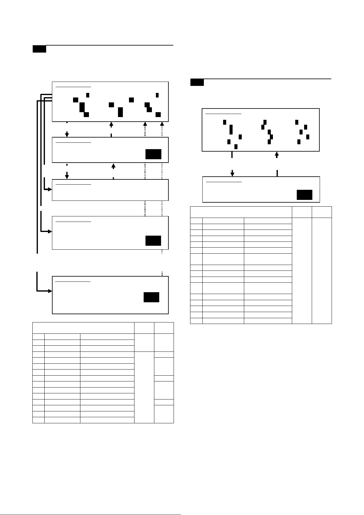
9-E Adjust the copied image gamma in copy
mode
1) Set the original on the original table.
2) Go through the modes specified in Simulation 46-18.
6) Press the P or Start key. Pressing the Start key starts copy
(print) operation as well as applying the adjustment value.
7) Check the copied image gamma (copy density levels for low
and high density areas) (contrast).
Repeat steps 5 to 7 until an acceptable copied image is obtained.
SIMULATION 46-18
GAMMA SETUP(COPIER). SELECT 1-14, AND PRESS START.
0.TRAY SELECT 1 1.PRINT START 2.EXP LEVEL 1
3.OC_AE 64 4.OC_CHARA 5.OC_MIX 64
6.OC_PHOTO 64 7.SPF_AE 64 8.SPF_CHARA 64
9.SPF_MIX 64 10.SPF_PHOTO 64 11.CIS_AE 64
12.CIS_CHARA 64 13.CIS_MIX 64 14.CIS_PHOTO 64
Select other than0-2,and
press [START] key.
SIMULATION 46-18
GAMMA SETUP. INPUT VALUE 0-127, AND PRESS START.
3.OC_AE
Press [SYSTEM SETTINGS] key.
64
Select 1,
and press
[START] key.
Select 0, and press [START] key.
Select 2, and press
[START] key.
0 TRAY SELECT Paper feed tray selection
1 PRINT START Print start (Default)
2 EXP LEVEL Exposure level selection
3 OC_AE AE mode (OC) 0 – 127 96
4 OC_CHARA Text mode (OC) 64
5 OC_MIX Text/Photo mode (OC)
6 OC_PHOTO Photo mode (OC)
7 SPF_AE AE mode (SPF) 96
8 SPF_CHARA Text mode (SPF) 64
9 SPF_MIX Text/Photo mode (SPF)
10 SPF_PHOTO Photo mode (SPF)
11 CIS_AE AE mode (CIS) 96
12 CIS_CHARA Text mode (CIS) 64
13 CIS_MIX Text/Photo mode (CIS)
14 CIS_PHOTO Photo mode (CIS)
3) Using the numeric keypad, select the number that corresponds
4) Press the Start key.
5) Enter the gamma adjustment value using the numeric keypad.
Press [START] key.
SIMULATION 46-18
GAMMA SETUP. NOW PRINTING.
SIMULATION 46-18
GAMMA SETUP. SELECT 1-6, AND PRESS START.
(FEED TRAY)
1.TRAY1 2.TRAY2 3.TRAY3 4.TRAY4
5.BPT 6.LCC
SIMULATION 46-18
GAMMA SETUP.
(EXP.LEVEL SELECT)
3.AUTO 4.1.0 5.2.0
6.3.0 7.4.0 8.5.0
9.AUTO(H) 10.1.0(H) 11.2.0(H)
12.3.0(H) 13.4.0(H) 14.5.0(H)
Press [SYSTEM SETTINGS]
key, or terminate copying.
Press [START] key, or press
[SYSTEM SETTINGS] key.
SELECT 3-14, AND PRESS START.
Item
Setting
range
1
1
Default
to the copy mode for which to make adjustments.
(Choose from numbers 3 to 14.)
A larger value provides larger gamma gradient and higher
image contrast.
9-F Adjust the copied image sharpness
1) Set the original on the original table.
2) Go through the modes specified in Simulation 46-31.
SIMULATION 46-31
SHARPNESS LEVEL SETUP. SELECT 1-12, AND PRESS START.
1.OC_AE 3 2.OC_CHARA 3 3.OC_MIX 3
4.OC_PHOTO 3 5.SPF_AE 3 6.SPF_CHARA 3
7.SPF_MIX 3 8.SPF_PHOTO 3 9.SPF2_AE 3
10.SPF2_CHARA 3 11.SPF2_MIX 3 12.SPF2_PHOTO 3
13.CIS_AE 3 14.CIS_CHARA 3 15.CIS_MIX 3
16.CIS_PHOTO 3
Press [START] key. Press [SYSTEM SETTINGS] key.
SIMULATION 46-31
SHARPNESS LEVEL SETUP. INPUT VALUE 0-3, AND PRESS
START.
1.OC_AE
Item
1 OC_AE AE mode (OC) 1 – 5 3
2 OC_CHARA Text mode (OC)
3 OC_MIX Text/Photo mode (OC)
4 OC_PHOTO Photo mode (OC)
5 SPF1_AE AE mode (SPF1)
6 SPF1_CHARA Text mode (SPF1)
7 SPF1_MIX Text/Photo mode
(SPF1)
8 SPF1_PHOTO Photo mode (SPF1)
9 SPF2_AE AE mode (SPF2)
10 SPF2_CHARA Text mode (SPF2)
11 SPF2_MIX Text/Photo mode
(SPF2)
12 SPF2_PHOTO Photo mode (SPF2)
13 CIS_AE AE mode (CIS)
14 CIS_CHARA Text mode (CIS)
15 CIS_MIX Text/Photo mode (CIS)
16 CIS_PHOTO Photo mode (CIS)
3) Using the numeric keypad, select the number that corresponds
to the copy mode for which to make adjustments.
(Choose from numbers 1 to 16.)
4) Press the Start key.
5) Adjust the sharpness by entering an appropriate value through
the numeric keypad.
A larger value provides higher sharpness.
6) Press the P or Start key.
Pressing the Start key starts copy (print) operation as well as
applying the adjustment value.
7) Check the copied image sharpness.
Repeat steps 5 to 7 until an acceptable copied image is obtained.
Setting
range
䋳
Default
MX-M700N ADJUSTMENTS 6 – 32
Page 84

ADJ 10 Adjusting the print quality in
fax mode
This adjustment is needed in the following situations:
* The CCD unit has been replaced.
* U2 trouble has occurred.
* The MFP control PWB has been replaced.
* The EEPROM on the MFP control PWB has been replaced.
* The scanner control PWB has been replaced.
* The EEPROM on the scanner control PWB has been replaced.
* One or more parts of the scanner (reading) section have been
replaced.
(Fax mode image density adjustment items)
Simulation for
Image mode
Adjust the fax
mode print density
in standard mode
Adjust the fax
mode print density
in small-character
mode
Adjust the fax
mode print density
in fine mode
Adjust the fax
mode print density
in super fine mode
Adjust the fax
mode print density
in 600dpi mode
Auto
Binary mode 46-12 46-13
mode
Manual Binary mode
Auto
Binary mode 46-14
mode
Half tone
mode
Manual Binary mode
Half tone
mode
Auto
Binary mode 46-15
mode
Half tone
mode
Manual Binary mode
Half tone
mode
Auto
Binary mode 46-16
mode
Half tone
mode
Manual Binary mode
Half tone
mode
Auto
Binary mode 46-45
mode
Half tone
mode
Manual Binary mode
Half tone
mode
(Fax mode density)
The print density settings should be normally left at defaults but
should be adjusted according to user requests, if any.
adjustment
All-mode
adjustment
Individual
mode
adjustment
10-A Adjust the fax mode print density for all
modes at once
1) Set the test chart (UKOG-0162FCZZ) on the original table so
that it aligns with the front frame. Then put four or five pieces of
A3 (11" x 17") paper.
0
0
2) Go through the modes specified in Simulation 46-12.
SIMULATION 46-12
EXP.LEVEL SETUP FAX(AUTO SET). SELECT 0-2, AND PRESS
START.
0.TRAY SELECT 1 1.COPY START
2.FAX EXP.LEVEL 50
Select other than0-1,and
press [START] key.
SIMULATION 46-12
EXP.LEVEL SETUP FAX(AUTO SET), INPUT VALUE 0-99, AND
PRESS START.
2.FAX EXP.LEVEL
Select 1,
and press
[START] key.
Select 0, and press
[START] key.
Press [START] key.
SIMULATION 46-12
EXP.LEVEL SETUP FAX(AUTO SET). NOW PRINTING.
SIMULATION 46-12
EXP.LEVEL SETUP FAX(AUTO SET).SELECT 1-6, AND PRESS
START.
(FEED TRAY)
1.TRAY1 2.TRAY2 3.TRAY3 4.TRAY4
5.BPT 6.LCC
Press [SYSTEM SETTINGS] key.
Press [SYSTEM SETTINGS] key,
or terminate copying.
Press [START] key, or press
[SYSTEM SETTINGS] key.
1
50
䋱
0 TRAY SELECT Paper feed tray
1 COPY START C opy START (Default)
2 FAX EXP. LEVEL FAX mode print density 0 – 99 50
3) Select the adjustment item (FAX EXP. LEVEL) using the
numeric keypad.
4) Press the Start key.
5) Press the Start key. (A copy is created.)
Check the print density.
If the print density is not at an acceptable level, do the following steps.
6) Enter the print adjustment value using the numeric keypad.
MX-M700N ADJUSTMENTS 6 – 33
Item
selection
Setting
range
Default
Page 85

7) Press the P or Start key.
This applies the adjustment value.
Pressing the Start key starts print operation as well as applying
the adjustment value.
8) Check the print density.
Repeat steps 5 to 8 until an acceptable print density is obtained.
Adjusting the Fax print density through this simulation changes the
print density settings for all Fax modes to the density level applied
by carrying out this simulation.
The Fax mode print density settings for individual Fax modes
adjusted through Simulations 46-13, -14, -15, -16 and -45 are
changed to the print density level applied by this simulation.
10-B Adjust the fax mode print density in
standard mode
10-C Adjust the fax mode print density in small-
character mode
10-D Adjust the fax mode print density in fine
mode
10-E Adjust the fax mode print density in super
fine mode
10-F Adjust the fax mode print density in 600dpi
mode
This adjustment is intended to the print mode for each Fax mode
individually. In manual mode, the print density setting for each print
density adjustment level (1 to 5) can be adjusted to a custom density level.
1) Set the test chart (UKOG-0162FCZZ) on the original table so
that it aligns with the front frame. Then put four or five pieces of
A3 (11" x 17") paper.
2) Go through the simulation modes that correspond to the Fax
modes for which to adjust the print density (i.e., the modes
specified in Simulations 46-13, -14, -15, -16, or -45).
SIMULATION 46-13
EXP.LEVEL SETUP FAX(NORMAL). SELECT 0-8, AND PRESS
START.
0.TRAY SELECT 1 1.PRINT START
2.EXP LEVEL 1
3.AUTO 50 4.1.0 50 5.2.0 50
6.3.0 50 7.4.0 50 8.5.0 50
Select other than0-2,
and press [START] key.
SIMULATION 46-13
EXP.LEVEL SETUP FAX(NORMAL),INPUT VALUE 0-99, AND
PRESS START.
4.1.0
Press [START] key.
Select 1,
and press
[START] key.
SIMULATION 46-13
EXP.LEVEL SETUP FAX(NORMAL). NOW PRINTING.
Select 0, and press [START] key.
SIMULATION 46-13
EXP.LEVEL SETUP FAX(NORMAL). SELECT 1-6, AND PRESS
START.
(FEED TRAY)
1.TRAY1 2.TRAY2 3.TRAY3 4.TRAY4
5.BPT 6.LCC
(ABOVE +20:DSPF MODE)
Select 2, and press
[START] key.
Press [SYSTEM SETTINGS]
key.
Press [SYSTEM SETTINGS]
key, or terminate copying.
Press [START] key, or press
[SYSTEM SETTINGS] key.
Press [START] key, or press
[SYSTEM SETTINGS] key.
1
50
㩷
1
SIMULATION 46-13
EXP.LEVEL SETUP FAX(NORMAL). SELECT 3-8, AND PRESS START.
(EXP.LEVEL SELECT)
3.AUTO 4.1.0 5.2.0
6.3.0 7.4.0 8.5.0
Item
0
0
0 TRAY SELECT Paper feed tray selection
1 PRINT START Print start (Default)
2 EXP LEVEL Exposure level selection
3 AUTO Auto 0 – 99 50
4 1.0 Exposure level 1
5 2.0 Exposure level 2
6 3.0 Exposure level 3
7 4.0 Exposure level 4
8 5.0 Exposure level 5
Setting
range
1
Default
MX-M700N ADJUSTMENTS 6 – 34
Page 86

SIMULATION 46-14
EXP.LEVEL SETUP FAX(FINE).SELECT 0-14,AND PRESS START.
0.TRAY SELECT 1 1.PRINT START
2.EXP LEVEL 1
3.AUTO 50 4.1.0 50 5.2.0 50
6.3.0 50 7.4.0 50 8.5.0 50
9.AUTO(H) 50 10.1.0(H) 50 11.2.0(H) 50
12.3.0(H) 50 13.4.0(H) 50 14.5.0(H) 50
[Binary mode]
(Copied image reference density)
1
Original
GRAY CHART
12 W109
R
876543
Select other than0-2,
and press [START] key.
SIMULATION 46-14
EXP.LEVEL SETUP FAX(FINE),INPUT VALUE 0-99, AND PRESS
START.
4.1.0
Select 1,
and press
[START] key.
Press [START] key.
SIMULATION 46-14
EXP.LEVEL SETUP FAX(FINE). NOW PRINTING.
Select 0, and press [START] key.
SIMULATION 46-13
EXP.LEVEL SETUP FAX(FINE). SELECT 1-6, AND PRESS START.
(FEED TRAY)
1.TRAY1 2.TRAY2 3.TRAY3 4.TRAY4
5.BPT 6.LCC
Select 2, and press
[START] key.
SIMULATION 46-14
EXP.LEVEL SETUP FAX(FINE). SELECT 3-14, AND PRESS START.
(EXP.LEVEL SELECT)
3.AUTO 4.1.0 5.2.0
6.3.0 7.4.0 8.5.0
9.AUTO(H) 10.1.0(H) 11.2.0(H)
12.3.0(H) 13.4.0(H) 14.5.0(H)
Press [SYSTEM SETTINGS]
key.
Press [SYSTEM SETTINGS]
key, or terminate copying.
Press [START] key, or press
[SYSTEM SETTINGS] key.
Press [START] key, or press
[SYSTEM SETTINGS] key.
50
Lot No.01A
Copy
GRAY CHART
12 W109
R
876543
Lot No.01A
If the copied test chart (UKOG-0162FCZZ) image includes a
background copy of patch 6 rather than patch 5, adjust allcopy mode to the image density level specified above.
[Half-tone mode]
(Copied image reference density)
1
Original
GRAY CHART
12 W109
R
876543
Lot No. 01A
1
Copy
Item
Setting
range
Default
0 TRAY SELECT Paper feed tray selection
1 PRINT START Print start (Default)
2 EXP LEVEL Exposure level selection
3 AUTO Auto 0 – 99 50
4 1.0 Exposure level 1
5 2.0 Exposure level 2
6 3.0 Exposure level 3
7 4.0 Exposure level 4
8 5.0 Exposure level 5
9 AUTO (H) Auto (Half-tone)
10 1.0 (H) Exposure level 1 (Half-tone)
11 2.0 (H) Exposure level 2 (Half-tone)
12 3.0 (H) Exposure level 3 (Half-tone)
13 4.0 (H) Exposure level 4 (Half-tone)
14 5.0 (H) Exposure level 5 (Half-tone)
3) Using the numeric keypad, select the number that corresponds
to the adjustment item. Choose from numbers 3 to 8 (14).
* Auto mode
* Manual mode (print density adjustment level)
For manual mode, select the number that corresponds to the
print density level (1 to 5). (Choose from numbers (4 to 8) (10-
14)).
4) Press the Start key.
5) Press the Start key. (A copy is created.)
GRAY CHART
12 W109
R
876543
Lot No. 01A
The copied test chart (UKOG-0162FCZZ) image includes a
background copy of patch 2 rather than patch 1.
If the print density is not at an acceptable level, do the following steps.
6) Adjust the copy density by entering an appropriate value
through the numeric keypad.
A larger value provides higher density.
7) Press the P or Start key.
This applies the adjustment value.
Pressing the Start key starts copy operation as well as applying the adjustment value.
8) Check the printed image density.
Repeat steps 6 to 8 until an acceptable image density is
obtained.
MX-M700N ADJUSTMENTS 6 – 35
Page 87

ADJ 11 Adjusting the image quality in
scan mode
This adjustment is needed in the following situations:
* The CCD unit has been replaced.
* U2 trouble has occurred.
* The MFP control PWB has been replaced.
* The EEPROM on the MFP control PWB has been replaced.
* The scanner control PWB has been replaced.
* The EEPROM on the scanner control PWB has been replaced.
* One or more parts of the scanner (reading) section have been
replaced.
(Scan mode image quality adjustment items)
2) Go through the modes specified in Simulation 46-21.
SIMULATION 46-21
EXP.LEVEL SETUP SCANNER(AUTO SET), PRESS START.
0.SCANNER EXP.LEVEL 50
Press [START] key. Press [START] key, or press
SIMULATION 46-21
EXP.LEVEL SETUP SCANNER(AUTO SET), INPUT VALUE 0-99,
AND PRESS START.
0.SCANNER EXP.LEVEL
[SYSTEM SETTINGS] key.
50
0
Simulation for
Image mode
Scan mode image
density
adjustment/
individual setup
(standard mode)
Scan mode image
density
adjustment/
individual setup
(small-character
mode)
Scan mode image
density
adjustment/
individual setup
(fine mode)
Scan mode image
density
adjustment/
individual setup
(super fine mode)
Auto
Binary mode 46-21 46-22
mode
Manual Binary mode
Auto
Binary mode 46-23
mode
Half tone
Manual Binary mode
Manual Binary mode
Manual Binary mode
mode
Half tone
mode
Auto
Binary mode 46-24
mode
Half tone
mode
Half tone
mode
Auto
Binary mode 46-25
mode
Half tone
mode
Half tone
mode
adjustment
All-mode
adjustment
Individual
mode
adjustment
(Scan mode image quality)
The image density settings should be normally left at defaults but
should be adjusted according to user requests, if any.
Setting
range
0 – 99 50
Default
0 SCANNER EXP.
LEVEL
Item
Scan mode image
density adjustment
3) Select the adjustment item SCANNER EXP. LEVEL using the
numeric keypad.
4) Press the Start key.
5) Enter the image density adjustment value.
6) Press the P or Start key.
NOTE: Adjusting the scanned image density through this simula-
tion changes the image density settings for all scan modes
to the image density level applied by carrying out this simulation.
The scan-mode image density settings for individual scan modes
adjusted through Simulations 46-22, -23, -24, -25, and -45 are
changed to the image density level applied by this simulation.
Scanned images must be visually checked to ensure the postadjustment image density.
11-B Scan mode image density adjustment/
individual setup (standard mode)
11-C Scan mode image density adjustment/
individual setup (small-character mode)
11-D Scan mode image density adjustment/
individual setup (fine mode)
11-A Adjust the scan mode image density for all
modes at once
1) Set the test chart (UKOG-0162FCZZ) on the original table so
that it aligns with the front frame. Then put four or five pieces of
A3 (11" x 17") paper.
0
0
MX-M700N ADJUSTMENTS 6 – 36
11-E Scan mode image density adjustment/
individual setup (super fine mode)
This adjustment is intended to the image mode for each scan mode
individually. In manual mode, the image density setting for each
scanned image density adjustment level (1 to 5) can be adjusted to
a custom density level.
1) Set the test chart (UKOG-0162FCZZ) on the original table so
that it aligns with the front frame. Then put four or five pieces of
A3 (11" x 17") paper.
0
0
Page 88

2) Go through the simulation modes that correspond to the scan
modes for which to adjust the scanned image density (i.e., the
modes specified in Simulations 46-22, -23, -24, or -25).
11-F Adjust the image gamma in scanner mode
1) Go through the modes specified in Simulation 46-27.
SIMULATION 46-21
EXP.LEVEL SETUP SCANNER(AUTO SET), PRESS START.
0.SCANNER EXP.LEVEL 50
Press [START] key. Press [START] key, or press
SIMULATION 46-21
EXP.LEVEL SETUP SCANNER(AUTO SET), INPUT VALUE 0-99,
AND PRESS START.
0.SCANNER EXP.LEVEL
Item
0 SCANNER EXP.
LEVEL
SIMULATION 46-22
EXP.LEVEL SETUP SCANNER(NORMAL). SELECT 0-5, AND PRESS
START.
0.AUTO 50 1.1.0 50 2.2.0 50
3.3.0 50 4.4.0 50 5.5.0 50
Select 0 - 5, and press
[START] key.
[SYSTEM SETTINGS] key.
Scan mode image
density adjustment
Press [START] key, or press
[SYSTEM SETTINGS] key.
Setting
range
0 – 99 50
50
0
1
Default
SIMULATION 46-27
GAMMA SETUP(SCNNER), SELECT 1-9, AND PRESS START.
1.OC_Fine.HT 64 2.OC_SFine.HT 64 3.OC_UFine.HT 64
4.SPF_Fine.HT 64 5.SPF_SFine.HT 64 6.SPF_UFine.HT 6
7.CIS_Fine.HT 64 8.CIS_SFine.HT 64 9.CIS_UFine.HT 64
Item
1 OC_Fine.HT Fine text (Half-tone) (OC)
2 OC_SFine.HT Super fine (Half-tone) (OC)
3 OC_UFine.HT Ultra fine (Half-tone) (OC)
4 SPF_Fine.HT Fine text (Half-tone) (SPF)
5 SPF_SFine.HT Super fine (Half-tone) (SPF)
6 SPF_UFine.HT Ultra fine (Half-tone) (SPF)
7 CIS_Fine.HT Fine text (Half-tone) (CIS)
8 CIS_SFine.HT Super fine (Half-tone) (CIS)
9 CIS_UFine.HT Ultra fine (Half-tone) (CIS)
4
2) Using the numeric keypad, select the number that corresponds
to the scan mode for which to make adjustments.
3) Press the Start key.
4) Adjust the gamma by entering an appropriate value through
the numeric keypad.
A larger value provides larger gamma gradient and higher
image contrast.
5) Press the Start key.
This applies the adjustment value.
Scanned images must be visually checked to ensure the postadjustment image gamma.
SIMULATION 46-22
EXP.LEVEL SETUP SCANNER(NORMAL), INPUT VALUE 0-99, AND
PRESS START.
0.AUTO
Item
0 AUTO Auto 0 – 99 50
1 1.0 Exposure level 1
2 2.0 Exposure level 2
3 3.0 Exposure level 3
4 4.0 Exposure level 4
5 5.0 Exposure level 5
50
Setting
range
Default
3) Enter the number that corresponds to the following adjustment
item using the numeric keypad. (Choose from numbers 0 to 5.)
* Auto mode
* Manual mode (print density adjustment level)
For manual mode, select the number that corresponds to the
image density adjustment level (1 to 5). (Choose from numbers 1 to 5.)
4) Press the Start key.
5) Enter the image density adjustment value.
6) Press the P or Start key.
Scanned images must be visually checked to ensure the postadjustment image density.
ADJ 12 Common image quality
adjustments for all of copy,
scan, and fax modes
(Common image quality adjustment items for all of copy, scan,
and fax modes)
Adjustment Item List Simulation for adjustment
Correct the image density in original
table mode/SPF mode (Copy mode)
Set up the auto mode operation for
copy, scan, and fax
12-A Original table mode/SPF mode image
density correction (copy mode)
Used to adjust the copy density correction in the DSPF copy mode
for the document table copy mode. The adjustment is made so that
the copy density becomes the same as that of the document table
copy mode.
This adjustment is needed in the following situations:
* The CCD unit has been replaced.
* U2 trouble has occurred.
* The MFP control PWB has been replaced.
* The EEPROM on the MFP control PWB has been replaced.
* The scanner control PWB has been replaced.
* The EEPROM on the scanner control PWB has been replaced.
* One or more parts of the scanner (reading) section have been
replaced.
* The CIS unit has been removed.
* The CIS unit has been replaced.
* The DSPF unit has been removed.
* The DSPF unit has been replaced.
46-20
46-19
MX-M700N ADJUSTMENTS 6 – 37
Page 89

1) Go through the modes specified in Simulation 46-20.
SIMULATION 46-20
OC/SPF EXP. ADJUSTMENT. SELECT 1-4, AND PRESS START.
0. TRAY SELECT 1 1. PRINT START
2. EXP LEVEL 1
3. SPF(FRONT) 128
4. SPF(REAR) 128
5. DSPF 128
Select other than0-2,andpress
[START] key.
SIMULATION 46-20
OC/SPF EXP. ADJUSTMENT. INPUT VALUE 0-255, AND PRESS
START.
1.SPF(FRONT)
Select 1,
and press
[START] key.
Select 0, and
press [START] key.
Select 2, and
press [START] key.
0 TRAY SELECT Paper feed tray selection
1 PRINT START Print start (Default) – –
2 EXP LEVEL Exposure level selection
3 SPF (FRONT) SPF (front)
4 SPF (REAR) SPF (front)
5 DSPF DSPF (Back surface)
Press [START] key.
SIMULATION 46-20
OC/SPF EXP. ADJUSTMENT. NOW PRINTING.
SIMULATION 46-20
OC/SPF EXP. ADJUSTMENT. SELECT 1-6, AND PRESS START.
(FEED TRAY)
2.TRAY1 2.TRAY2 3.TRAY3 4.TRAY4
5.BPT 6.LCC
SIMULATION 46-20
OC/SPF EXP. ADJUSTMENT. SELECT 3-8, AND PRESS START.
(EXP. LEVEL SELECT)
3.1.0 4.1.5 5.2.0
6.2.5 7.3.0 8.3.5
9.4.0 10.4.5 11.5.0
Item Content
1: TRAY1
2: TRAY2
3: TRAY3
4: TRAY4
5: Manual feed
6: Side LCC
3:Exposure level1.0
4:Exposure level1.5
5:Exposure level2.0
6:Exposure level2.5
7:Exposure level3.0
8:Exposure level3.5
9:Exposure level4.0
10:Exposure level4.5
11:Exposure level5.0
(front frame side)
(rear frame side)
(rear frame side)
Press [SYSTEM SETTINGS] key.
Press [SYSTEM SETTINGS]
key, or terminate copying.
㩷
Press [START] key, or
press [SYSTEM SETTINGS] key.
Press [START] key, or
press [SYSTEM SETTINGS] key.
Setting
0 – 255 128
1
128
1
1
range
Default
––
––
2) Using the mumeric keypad, select the number that corresponds to the mode for which to make adjustments.
DSPF front frame side (front face copy), DSPF rear frame side
(front face copy), DSPF (back side copy) (Choose from numbers 3 to 5.)
3) Press the Start key.
4) Enter the density correction value using the numeric keypad.
5) Press the P or Start key.
6) Make two copies (one in original table mode and the other in
DSPF mode) and compare the copies in terms of density.
Repeat steps 4 to 6 until both copies provide the same density.
12-B Set up the auto mode operation for copy,
scan, and fax
This adjustment is needed in the following situations:
* U2 trouble has occurred.
* The MFP control PWB has been replaced.
* The EEPROM on the MFP control PWB has been replaced.
* The scanner control PWB has been replaced.
* The EEPROM on the scanner control PWB has been replaced.
1) Go through the modes specified in Simulation 46-19.
SIMULATION 46-19
EXP.MODE SETUP. SELECT 1-2, AND PRESS START.
1.AE MODE 1
2.AE STOP MODE(COPIER) 1
3.AE STOP MODE(SCANNER)0
4.AE STOP MODE(FAX) 0
Select 1, and press [START] key. Press [SYSTEM SETTINGS]
SIMULATION 46-19
EXP.MODE SETUP. INPUT VALUE 1-2, AND PRESS START.
1.AE MODE
key.
1
Select 2, 3, or 4 and
press [START] key.
SIMULATION 46-19
EXP.MODE SETUP. INPUT VALUE 0-1, AND PRESS START.
2.AE STOP MODE(COPIER)
Press [START] key, or press
[SYSTEM SETTINGS] key.
0
Mode
AE mode 1 Image quality priority mode
AE fixed mode 0 AE fixed OFF 1 (COPIER)
2) Select "1 AE MODE" using the numeric keypad.
3) Press the Start key.
4) Using the numeric keypad, select the number that corresponds
to the operation spec.
5) Press the Start key. Pressing the Start key applies the setting.
(Auto copy mode operation setting)
1) Using the numeric keypad, select the number that corresponds
to the mode for which to make adjustments. (Choose from
numbers 2 to 4.)
2) Press the Start key.
3) Using the numeric keypad, select the number that corresponds
to the operation mode.
4) Press the Start key.
AE fix OFF: Density (exposure) is automatically controlled on a real
time basis. (The density level is dynamically changed according to
the original's pattern.)
AE fix ON: The density of the leading edge of the original is
detected and used to determine the overall density (exposure)
level. (The overall density level is fixed.)
Set
value
(Normal mode)
* Gamma is sharp to
2 Toner consumption priority
mode
* Gamma is mild to provide
1 AE fixed ON
Item Default
provide high contrast
images.
low contrast images.
2
0 (SCANNER/
FAX)
MX-M700N ADJUSTMENTS 6 – 38
Page 90

ADJ 13 Adjusting the fusing paper
SIMULATION 40-2
BYPASS TRAY ADJUSTMENT.
MIN. POSITION ··· COMPLETE (or "ERROR")
guide position
This adjustment is needed in the following situations:
* Paper is jammed in or around the fusing section.
* Imperfect images, deformed images, or wrinkles are produced in
the paper lead edge section or the rear edge section.
Adjust the fusing paper guide position by loosening the fusing
paper guide fixing screws and the sliding the fusing paper guide in
the arrow direction.
ADJ 14 Adjusting the paper size
detection
14-A Adjust the paper width sensor for the
manual paper feed tray
This adjustment is needed in the following situations:
* The manual paper feed tray section has been disassembled.
* The manual paper feed tray unit has been replaced.
* U2 trouble has occurred.
* The PCU PWB has been replaced.
* The EEPROM of the PCU PWB has been replaced.
1) Go through the modes specified in Simulation 40-2.
SIMULATION 40-2
BYPASS TRAY ADJUSTMENT. SELECT 1-4, AND PRESS START.
1. MAX. POSITION
2. POSITION 1
3. POSITION 2
4. MIN. POSITION
1
When shipping, it is fixed to the position which is one scale
(0.5mm) over the center.
Select 1, and press [START] key.
SIMULATION 40-2
BYPASS TRAY ADJUSTMENT.
MAX. POSITION ··· COMPLETE (or "ERROR")
Select 2, and
press [START] key.
SIMULATION 40-2
BYPASS TRAY ADJUSTMENT.
POSITION 1 ··· COMPLETE (or "ERROR")
Select 3, and press [START] key.
SIMULATION 40-2
BYPASS TRAY ADJUSTMENT.
POSITION 2 ··· COMPLETE (or "ERROR")
Select 4 and press
[START] key.
Press [SYSTEM SETTINGS] key.
Press [SYSTEM SETTINGS] key.
Press [SYSTEM SETTINGS] key.
Press [START] key, or press
[SYSTEM SETTINGS] key.
2) Open the manual paper feed guide to the maximum width
position.
MX-M700N ADJUSTMENTS 6 – 39
Page 91

3) Select MAX. POSITION using the numeric keypad.
4) Press the Start key.
The maximum width detection level is recognized.
5) Press the SYSTEM SETTINGS key.
6) Set the manual paper feed guide to the width for the A4R size.
7) Select POSITION 1 using the numeric keypad.
8) Press the Start key.
The A4R width detection level is recognized.
9) Press the SYSTEM SETTINGS key.
10) Set the manual paper feed guide to the width for the A5R size.
11) Select POSITION 2 using the numeric keypad.
12) Press the Start key.
The A5R width detection level is recognized.
13) Press the SYSTEM SETTINGS key.
14) Open the manual paper feed guide to the minimum width position.
14-B Adjust the paper width sensor for paper
feed tray 3
This adjustment is needed in the following situations:
* The paper feed tray section has been disassembled.
* The paper feed tray unit has been replaced.
* U2 trouble has occurred.
* The PCU PWB has been replaced.
* The EEPROM of the PCU PWB has been replaced.
1) Go through the modes specified in Simulation 40-12.
SIMULATION 40-12
TRAY3 ADJUSTMENT. SELECT 1-2, AND PRESS START.
1. MAX. POSITION
2. MIN. POSITION
1
Select 1, and press [START] key.
Press [SYSTEM SETTINGS] key.
SIMULATION 40-12
TRAY3 ADJUSTMENT.
MAX. POSITION ··· COMPLETE (or "ERROR")
Press [START] key. Press [SYSTEM SETTINGS] key.
SIMULATION 40-12
TRAY3 ADJUSTMENT.
MIN. POSITION ··· COMPLETE (or "ERROR")
2) Open the paper feed guide to the maximum width position.
A4
A3
1
1
1
2
2
2
A5
A4B4B5
B5
5
11
7
8
15) Select MIN. POSITION using the numeric keypad.
16) Press the Start key.
The minimum width detection level is recognized.
* When each of the above operations has been completed, the
"COMPLETE" message appears; when any of the operations
has failed, the "ERROR" message appears.
3) Select MAX. POSITION using the numeric keypad.
4) Press the Start key.
The maximum width detection level is recognized.
5) Press the SYSTEM SETTINGS key.
6) Open the paper feed guide to the maximum width position.
MX-M700N ADJUSTMENTS 6 – 40
Page 92

7) Select MIN. POSITION using the numeric keypad.
8) Press the Start key.
The maximum width detection level is recognized.
* When each of the above operations has been completed, the
"COMPLETE" message appears; when any of the operations
has failed, the "ERROR" message appears.
14-C Adjust the paper width sensor for the DSPF
paper feed tray
This adjustment is needed in the following situations:
* The paper feed tray section has been disassembled.
* The paper feed tray unit has been replaced.
* U2 trouble has occurred.
* The scanner PWB has been replaced.
* The EEPROM on the scanner PWB has been replaced.
1) Go through the modes specified in Simulation 53-6.
SIMULATION 53-6
SPF TRAY ADJUSTMENT. SELECT 1-4, AND PRESS START.
1.MAX.POSITION
2.POSITION 1
3.POSITION 2
4.MIN.POSITION
Select 1, and press [START] key.
SIMULATION 53-6
SPF TRAY ADJUSTMENT.
MAX.POSITION ... COMPLETE (or “ERROR”)
Select 2, and
press [START] key.
Press [SYSTEM SETTINGS] key.
Press [SYSTEM SETTINGS] key.
1
2) Open the DSPF paper feed guide to the maximum width position.
3) Select MAX. POSITION using the numeric keypad.
4) Press the Start key.
The maximum width detection level is recognized.
5) Press the SYSTEM SETTINGS key.
6) Open the DSPF paper feed guide to the width for the A4R size.
7) Select POSITION 1 using the numeric keypad.
8) Press the Start key.
The A4R width detection level is recognized.
9) Press the SYSTEM SETTINGS key.
10) Open the DSPF paper feed guide to the width for the A5R size.
11) Select POSITION 2 using the numeric keypad.
12) Press the Start key. The A4R width detection level is recognized.
13) Press the SYSTEM SETTINGS key.
14) Open the DSPF paper feed guide to the minimum width position.
SIMULATION 53-6
SPF TRAY ADJUSTMENT.
POSITION 1 ... COMPLETE (or “ERROR”)
Select 3, and press [START] key.
SIMULATION 53-6
SPF TRAY ADJUSTMENT.
POSITION 2 ... COMPLETE (or “ERROR”)
Select 4 and press
[START] key.
SIMULATION 53-6
DSPF TRAY ADJUSTMENT.
MIN.POSITION ... COMPLETE (or “ERROR”)
Press [SYSTEM SETTINGS] key.
Press [START] key, or press
[SYSTEM SETTINGS] key.
15) Select MIN. POSITION using the numeric keypad.
16) Press the Start key. The maximum width detection level is recognized.
* When each of the above operations has been completed, the
"COMPLETE" message appears; when any of the operations
has failed, the "ERROR" message appears.
MX-M700N ADJUSTMENTS 6 – 41
Page 93

ADJ 15 Adjusting the original size
detection (in original table
mode)
This adjustment is needed in the following situations:
15-
* The original size sensor section has been disassembled.
* The original size sensor section has been replaced.
* U2 trouble has occurred.
* The scanner control PWB has been replaced.
* The EEPROM on the scanner control PWB has been replaced.
15-A Adjust the detection point of the original
size sensor (in original table mode)
1) Go through the modes specified in Simulation 41-1.
SIMULATION 41-1
PD SENSOR CHECK..
OCSW PD1 PD2 PD3 PD4 PD5 PD6 PD7
2) Gradually turn over the original detection arm unit in the arrow
direction, and loosen the original cover switch actuator adjusting screw so that the OCSW indicator changes from inverse
video to normal video when the arm unit top reaches a height
of 32r0.5mm from the table glass. Then move the actuator to
adjust its position. (If the original cover switch turns on in
improper timing, the original detection mechanism mail fail to
operate correctly.)
15-B Adjust the sensitivity of the original size
sensor
1) Go through the modes specified in Simulation 41-2.
SIMULATION 41-2
PD SENSOR ADJUSTMENT. SELECT1-2, AND PRESS START.
(PLEASE OPEN THE ORIGINAL COVER.)
1. NO ORIGINAL
2. A3 ORIGINAL
Select 1, and press [START] key.
Press [SYSTEM SETTINGS] key.
SIMULATION 41-2
PD SENSOR ADJUSTMENT.
NO ORIGINAL ··· COMPLETE (or "ERROR at PD1 PD2...")
A3 ORIGINAL ··· INCOMPLETE
Select 2 and press
[START] key. (Error)
SIMULATION 41-2
PD SENSOR ADJUSTMENT.
NO ORIGINAL ··· COMPLETE
A3 ORIGINAL ··· COMPLETE (or "ERROR at PD1 PD2...")
2) Open the original cover. With nothing placed on the original
table, select NO ORIGINAL using the numeric keypad.
3) Press the Start key.
This sets the sensor level with no original detected.
4) Set A3 (11" x 17") paper on the original table, and select A3
ORIGINAL using the numeric keypad.
5) Press the Start key. This sets the sensor level with an original
detected.
When each of the above operations has been completed, the
"COMPLETE" message appears; when any of the operations has
failed, the "ERROR" message appears.
Press [START] key, or press
[SYSTEM SETTINGS] key.
1
Original detection arm unit
+
32 5mm
-
Table glass
ADJ 16 Adjusting the touch panel
coordinates
This adjustment is needed in the following situations:
* The operation panel has been replaced.
* U2 trouble has occurred.
* The MFP control PWB has been replaced.
* The EEPROM on the MFP control PWB has been replaced.
1) Go through the modes specified in Simulation 65-1.
SIMULATION 65-1
Original cover switch actuator
2) Press the four cross mark points.
Pressing the cross mark points correctly results in gray display. When the touch panel adjustment is complete with the
four points pressed, the sub-number entry screen for simulation reappears.
If any error is detected, the touch panel returns to adjustment
mode.
NOTE: Never use something with a sharp tip (such as a needle or
pin) to press the touch panel.
MX-M700N ADJUSTMENTS 6 – 42
Page 94

ADJ 17 Adjusting the supply voltage
This adjustment is needed in the following situations:
* One or more parts of the DC main power supply unit have been
replaced.
* One or more parts of the DC sub power supply unit have been
replaced.
(24 V supply voltage adjustment)
1) Apply a digital multi-meter to the DC main PWB 24 V line
(CN3, 1 pin) and GND (CN3, 4 pin).
2) Turn RV202 on the DC main power supply PWB so that the
voltage is 24 V.
(12 V supply voltage adjustment)
5) Apply a digital multi-meter to the DC sub PWB 12 V line (CN4,
1 pin) and GND (CN4, 6 pin).
6) Turn RV102 on the DC sub power supply PWB so that the voltage is 12 V.
GND +12V
(CN4, 6pin) (CN4, 1pin)
RV102
RV202 (CN3, 4pin) (CN3, 1pin)
GND +24V
(38 V supply voltage adjustment)
3) Apply a digital multi-meter to the DC main PWB 38 V line
(CN8, 1 pin) and GND (CN8, 4 pin).
4) Turn RV201 on the DC main power supply PWB so that the
voltage is 38 V.
RV201
GND +38V
(CN8, 4pin) (CN8, 1pin)
MX-M700N ADJUSTMENTS 6 – 43
Page 95

MX-M700N
[7] SIMULATION
1. Adjustment value/Simulation and
storage data
A. Simulation adjustment value/ Set value data
Each controller is provided with an EEPROM. The adjustment/set
values are collected to the MFP controller. If they are changed, they
are sent back and saved.
MFP CONTROLLER
LCD
When the value is changed,
it is sent and saved.
Saved adjustment value
send (When the power is
turned on, etc.)
ENGINE
CONTROLLER
B. Each storage data
(1) (Data saved by the PCU PWB)
Counters Adjustment value Others
Drum rotation time
counter
(Accumulated time)
Developer unit
rotation time counter
Toner supply time
(Block IC CHIP)
Drum rotating time
(Block IC CHIP)
Total counter Transfer belt cleaning
Maintenance
counter
Developing counter Density correction start set
Drum counter Density correction rotation
Toner cartridge
counter
Valid paper counter Correction execution
Tray 1 paper feed
counter
Tray 2 paper feed
counter
Tray 3 paper feed
counter
Tray 4 paper feed
counter
Manual paper feed
counter
Developing bias voltage
value
Cleaning mode
Developing bias voltage
value
Main high voltage
adjustment
Transfer charger voltage
value
voltage value
Toner concentration
reference value
time (Developer unit)
time (Developer tank)
Density correction amo unt
(Developer tank)
direction, upper/lowe r limit
(Developer tank)
Toner concentration
temperature correction (low
temperature side) correction
amount
Toner concentration
temperature correction (low
temperature side) set
temperature
Toner concentration
temperature correction (low
temperature side) release
temperature
Toner concentration
temperature correction (high
temperature) correction
amount
Toner concentration
temperature correction (high
temperature side) judgment
temperature
-
SCANNER
CONTROLLER
Serial number
Trouble history
Tray 1 si ze
Tray 2 si ze
Manual desti nation
information
Tray 3 destination
information
Tray 4 destination
information
Tray 1 paper
remaining quantity
data
Tray 2 paper
remaining quantity
data
Tray 3 paper
remaining quantity
data
Tray 4 paper
remaining quantity
data
Final toner
concentration
sensor output
value
Toner cartridge IC
CHIP destination
Counter mode
setting
Counters Adjustment value Others
5GTXKEG/CPWCN
ADU paper feed
counter
Staple counter Toner concentration
Punch counter Toner concentration
Main unit right-side
paper exit counter
Side LCC paper
feed counter
Inserter counter Manual width adjustment
Saddle staple
counter
Fuser Web Send
counter
Toner concentration
temperature correction (high
temperature side) judgment
voltage
temperature correction (high
temperature side) correction
value
temperature correction (low
temperature side) release
time
Toner concentration
temperature correction (high
temperature side) toner
concentration delay time
Multi-purpose width
adjustment value
value
Heater lamp temperature
(Center, normal control)
Lead edge adjustment
Led edge void set value
Rear edge void set value
Side edge setting
Print off-center adjustment
value
Resist amount adjustment
value
Laser power adjustment
value
PPD1 sensor adjustment
Process correction inhibit
allow set value
Developing bias ri sing
correction wait time
Developing bias ri sing
correction adjustment value
Built-in finisher jogger
position adjustment
Saddle adjustment value
White paper exit
count setting
Trouble memory
mode setting
Fusing operation
mode (Prevention
against curl)
CE mark
conforming
operation mode
Maintenance cycle
Print stop setting
when developer
life over
Saddle alignment
operation priority
mode
(2) (Data saved by the scanner control PWB)
Counters Adjustment value Others
Scan counter Document lead edge
SPF paper pass
counter
SPF stamp counter Document image loss
adjustment value
Document off-center
adjustment value
amount adjustment value
Document image loss
amount adjustment value
SPF resist amount
adjustment value
Exposure motor speed
adjustment value
Platen document detection
adjustment value
SPF size width detection
adjustment value
Touch panel adjustment
value
Exposure level adjustment
value
gamma change value
OC/SPF exposure
correction value
Shading adjustment value
(CCD/CIS)
CCD shading start position
adjustment value
Exposure mode set
value
Scanner serial
number
MX-M700N SIMULATION 7 – 1
Page 96

(3) (Data saved by the MFP control PWB)
Counters Adjustment value Others
Copy counter FAX SOFT SW., etc. Trouble history
Printer counter JAM history
FAX receive counter Destination setting
FAX send counter La nguage setting
All valid paper
counter
Trouble counter 13" setting
JAM counter Auditor setting
Toner save mode
setting
Counter mode
setting
Trouble memory
mode setting
Center binding
mode AMS setting
PC/MODEM
communication
trouble detection
YES/NO setting
Tag number set
value
Printers set values
Network set value
(4) (Detailed list)
Refer to the "3. List of simulation codes".
2. General
The simulation has the following functions to grasp the machine
operating status, identif y the trouble position and causes in an earlier stage, and make various setups and adjustments speedily for
improving the serviceability of the machine.
1) Various adjustments
2) Setting of the specifications and functions
3) Canceling troubles
4) Operation check
5) Counters check, setting, clear
6) Machine operating conditions (operation hysteresis), data
check, clear
7) Various (adjustments, setting, operation, counters, etc.) data
transf er
The operating procedures and displays depend on the form of the
operation panel of the machine.
A. Basic operation
(1) Starting the simulation
* Entering the simulation mode
1) Copy mode key ON → Program key ON → Asterisk (*) key ON
→ CLEAR key ON → Asterisk (*) key ON → Ready for input of
a main code of simulation
2) Entering a main code with the 10-key -> [START] key. ON
3) Entering a sub code with the 10-key -> [START] key. ON
4) Select an item with the scroll key and the item key.
5) The machine enters the mode corresponding to t he selected
item.
Press [START] key. or EXECUTE key to start the simulation
operation.
To cancel the current simulation mode or to change the main
code and the sub code, press the user setup key.
* Canceling the simulation mode to return to the normal mode
1) Press CA key.
(Note for the simulation mode)
• Do not turn OFF the power switch on the operation panel when
the machine is in the simulation mode.
When executing the operation of mentioning above, a malfunction may be resulted. In this case, turn OFF /ON the main power
source.
• Befor e entering the simulation mode, check to insure that neither
print data nor FAX data are receiving.
MX-M700N SIMULATION 7 – 2
Page 97

Select copy mode
Press the Program key.
Press the asterisk (*) key.
Press the clear key.
Press the Program key.
Standby for entry of SIM
sub code
Enter SIM sub code with
the 10-key.
Press the START button.
If there is no item.
Standby for entry of
SIM code.
Enter the main code of
SIM with the 10-key.
The main code of SIM
is displayed.
Press the START button.
YES
Is there a sub code ?
Select the mode and the
item with the scroll key
and the item key.
Operation check ?
Operating conditions
check ?
NO
NO
NO
Press the SYSTEM
SETTINGS key
<Exclusion type>
You have to exit
simulation mode
before entering into
this mode for self
printing type.
YES
Press the EXECUTE button
and OK button.
Operation is made according
to the selected mode and item.
YES
Press the EXECUTE button
and OK button.
The display is made according to
the selected some and the item.
YES
Press the SYSTEM
NO
NO
Is it the same
simulation main
code?
In the power OFF/ON type
SETTINGS key
YES
Do you want
to perform another
simulation ?
NO
Do you
want to end the
simulation ?
simulation, OFF/ON
message is
displayed by the
SYSTEM
SETTINGS key.
The simulation mode
is canceled.
YES
Press the clear all key.
YES
The display is made according
to the selected mode and the item.
Data clear ?
NO
Adjustments
or setting (counter data
change) ?
Do you
want to change the
content ?
YES
Enter the new setting and
;'5
adjustment values.
MX-M700N SIMULATION 7 – 3
YES
Press the EXECUTE button
and OK button.
The selected mode and
the item are cleared.
Operation is made according
NO
to the selected mode and the item.
(Other modes)
NO
Press the EXECUTE button
and OK button.
The changed content
is stored.
Page 98
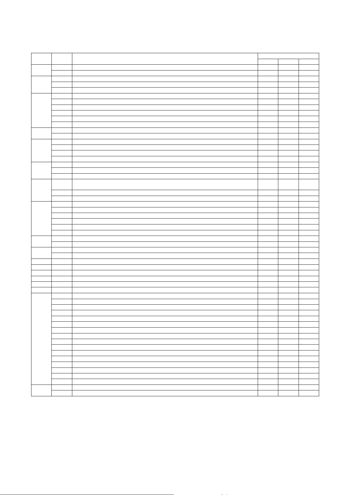
3. List of simulation codes
Main
code
10 1 Toner moto r activation {
13 U1 trouble cancellation {
14 Trouble cancellation {
15 LCC trouble cancellation {{
16 U2 trouble cancellation {{{
17 PF trouble cancellation {
21 1 Maintenance cycle s et up {
22 1 Counter data display {{{
23 2 JAM/trouble data print mode {
Sub
code
1 1 Mirror scan operation {
2 Optical system sensor check {
2 1 SPF operation aging {
2 SPF sensor check {
3 SPF individual load check {
3 2 Finisher sensor check {
3 Finisher individual load check {
10 Finisher setting {
30 Inserter sensor check {
31 Inserter load operation {
32 Inserter tray value setting {
4 2 LCC sensor check {
3 LCC individual load check {
5 1 LCD/LED test {
2 Heate r lamp test {
3 Copy lamp test {
4 Discharge lamp test {
6 1 Transport system load operation (Clutch/Solenoid) {
2 Fan motor test {
3 Transfer separation motor operation {
7 1 Operation registration (jam detection:No, develo ping tank detection:No, aging and maintenance warm-
up:No, intermittent operation:Yes, shading:No etc.)
6 Intermittent aging cycle setting {
8 Warm-up time display (No aging) {
8 1 DV bias setting {
2 Main charger grid voltage setting {
6 Transfer voltage setting {
17 Transfer roller setting {
18 Transfer cleaning roller setting {
19 Fusing bias setting (Not used) {
9 1 ADU output test {
2 ADU sensor check {
2 Toner rest sensor check {
2 JAM/Trouble counter data display {
3 Pap er jam history {
4 Trouble history {
5 ROM version data display {{{
6 Data print mode {
7 Key operator code display {
8 ORG/Staple counter data display
9 Pap er feed counter data display {
10 System information {
11 FAX counter data display {
12 SPF JAM history {
13 Proc ess data display {
19 Network scanner counter display { (FAX)
30 OSA vendor ID display (A pplication Communication) {
31 OSA vendor ID display (E xternal account) {
80 Data print mode {
Operation content
Data save destination/Target
MFP Scanner Engine
{
{{
MX-M700N SIMULATION 7 – 4
Page 99

Main
code
24 1 JAM/Trouble counter data clear {
25 1 Toner concentration sensor monitor {
26 2 Size setting {
27 1 PC/MODEM communication trouble (U7-00) detection YES/NO setting {
30 1 Main unit sensor check {
40 1 Manual paper feed size width detection check {
41 1 Document size detection photo sensor check {
43 1 Fusing temperature control temperature setting (Normal/Energy-save mode) {
44 1 Process correction inhibit/allow setting {
46 2 Copy exposure level adjustment (binary) {{
Sub
code
2 Pap er feed counter clear {
3 ORG/Staple counter clear {{
4 Maintenance counter data clear {
5 Dev eloper counter data clear {
6 Copy counter data clear {
7 Drum/Toner counter data clear {
9 Prin ter/Other counter data clear {
10 FAX counter da ta clear {
11 Various rotation time timer clear {
15 Network scanner counter data clear { (FAX)
2 Aut o developer adjustment {
3 Auditor setting {
5 Counter mode setting {
6 Destination setting {
10 Network scanner trial mode setting {
18 Toner save mode setting {
30 CE m ark conformity control inhibit/allow setting {
35 Trouble memory mode setting {
38 Prin t stop setting when life over {
41 Cente r binding mode AMS setting {
50 Black-White reverse function valid/invalid setting {
52 White paper exit count-up setting {{
68 CA key cancel function valid/invalid {
5 Tag number setting {
2 Tray sensor check {
2 Manu al paper feed size width detection level adjustment {
7 Manu al paper feed size width detection adjustment value input {
11 MPT size width detection check {
12 MPT size width detection level adjustment {
2 Doc ument size detection photo sensor detect ion level {
3 Doc ument size detection photo sensor light receiving/detection level check {
3 Fusing roller RPM setting. {
2 DM/ID sensor gain adjus tment {
4 Standard patch de nsity setting {
5 Pat ch making reference condition setting {
9 Proc ess control data display {
12 Process control patch data di splay {
14 Temperature/humidity sensor output monitor {
16 Toner concentration reference value check {
9 Copy exposure level adj ustment/individual setting (Text binary) {{
10 Copy exposure level adjustment, individual setting (Text/Photo binary) {{
11 Copy exposure level adjustment, individual setting (Photo binary) {{
12 FAX exposure level adjustment (1 m ode auto adjustment) {{
13 FAX exposure level adjustment, indi vidual setting (Normal text) {{
14 FAX exposure level adjustment, indi vidual setting (Fine) {{
15 FAX exposure level adjustment, indi vidual setting (Super Fine) {{
16 FAX exposure level adjustment, indi vidual setting (Ultra Fine) {{
17 Shading reference value change (Gain adjustment) {
18 gamm a change (Copier mo de) {
19 Exposure mode setting {
20 OC/SPF exposure correction {
21 Scanner exposure level adjustment (1 mode auto adjustment) {
22 Scanner exposure level adjustment, individual setting (Normal text) {
23 Scanner exposure level adjustment, individual setting (Fine) {
24 Scanner exposure level adjustment, individual setting (Super Fine) {
25 Scanner exposure level adjustment, individual setting (Ultra Fine) {
27 gamm a change (Scanner mode) {
31 Copy sharpness setting {
39 FAX sharpness setting {
45 FAX exposure level adjustment, individual setting (600dpi) {{
Operation content
Data save destination/Target
MFP Scanner Engine
MX-M700N SIMULATION 7 – 5
Page 100

Main
code
48 1 Magnification ratio ad justment (by Input/Output) {{
49 1 Firmware update {{{
50 1 Copy lead edge adjustment (Document table ) {{{
51 2 Resist amount adjus tment {{
53 6 SPF size width detection level adjustment {
55 1 Engine soft SW change and check {
56 1 Data transfer {
60 1 ICU image DRAM read /write check {
61 1 LSU operation check {
62 1 Hard disk format {
63 1 Shading check {
64 1 Self print {
65 1 Touch panel adjustment {
Sub
code
5 Moto r speed adjustment {
2 Lead edge adjustment (Document table simple type) {{{
5 Print lead edge adjustment {{
6 Copy lead edge adjustment (SPF) {{{
7 Copy lead edge adjustment (SPF simple type) {{{
10 Prin t off-center adjustment {{
12 Document off-center adjustment {{
27 Document image loss setting (FAX send/scanner mode) {
7 SPF size width detection a djustment value inpu t {
8 SPF scan position adjustment {
2 Scanner soft SW change and check {
3 Controller soft SW change a nd check {
2 Laser power setting (Copier) {
3 Laser power setting (FAX) {
4 Laser power setting (Printer) {
2 Hard disk read/write check {
3 Hard disk read/write check (All areas) {
6 HDD self diag {
7 Self diag error log print {
8 Hard disk format (Excluding the system area) {
9 HDD format (system area) {
10 Job complete list delete {
11 Document filing data delete {
2 Sha ding execution {
7 White plate scan start position adjustment {
2 Touch panel check {
Operation content
Data save destination/Target
MFP Scanner Engine
MX-M700N SIMULATION 7 – 6
 Loading...