

Page 1

DIGITAL MULTIFUNCTIONAL SYSTEM
START GUIDE
MODEL: MX-M623U
MX-M753U
Keep this manual close at hand for reference whenever needed.
Page 2
Caution!
For complete electrical disconnection, pull out the main plug.
The socket-outlet shall be installed near the equipment and shall be easily accessible.
Shielded interface cables must be used with this equipment to maintain compliance with EMC regulations.
➢➣➢➣➢➣➢➣➢➣➢➣➢➣➢➣➢➣➢➣➢➣➢➣➢➣➢➣➢➣➢➣➢➣➢➣➢➣➢➣➢➣➢➣➢➣➢➣➢➣➢➣➢➣➢
The equipment should be installed near an accessible socket outlet for easy disconnection.
Notice for users in the UK
MAINS PLUG WIRING INSTRUCTIONS
The mains lead of this equipment is already fitted with a mains plug which is either a non-rewireable
(moulded) or a rewireable type. Should the fuse need to be replaced, a BSI or ASTA approved fuse
to BS1362 marked or
be used.
Always refit the fuse cover after replacing the fuse on the moulded plug. Never use the plug without
the fuse cover fitted.
In the unlikely event of the socket outlet in your home not being compatible with the plug supplied
either cut-off the moulded plug (if this type is fitted) or remove by undoing the screws if a rewireable
plug is fitted and fit an appropriate type observing the wiring code below.
DANGER: The fuse should be removed from the cut-off plug and the plug destroyed immediately
and disposed of in a safe manner. Under no circumstances should the cut-off plug be inserted
elsewhere into a 13A socket outlet as a serious electric shock may occur.
To fit an appropriate plug to the mains lead, follow the instructions below:
IMPORTANT: The wires in this mains lead are coloured in accordance with the following code:
As the colours of the wires in this mains lead may not correspond with coloured markings
identifying the terminals in your plug, proceed as follows:
The wire which is coloured GREEN-AND-YELLOW must be connected to the terminal in the plug
which is marked with the letter E, or by the safety earth symbol , or coloured green or greenand-yellow.
The wire which is coloured BLUE must be connected to the terminal which is marked with the letter
N or coloured black.
The wire which is coloured BROWN must be connected to the terminal which is marked with the
letter L or coloured red.
If you have any doubt, consult a qualified electrician.
WARNING: THIS APPARATUS MUST BE EARTHED.
and of the same rating as the one removed from the plug must
GREEN-AND-YELLOW: Earth
BLUE: Neutral
BROWN: Live
➣➢➣➢➣➢➣➢➣➢➣➢➣➢➣➢➣➢➣➢➣➢➣➢➣➢➣➢➣➢➣➢➣➢➣➢➣➢➣➢➣➢➣➢➣➢➣➢➣➢➣➢➣➢➣➢
➢➣➢➣➢➣➢➣➢➣➢➣➢➣➢➣➢➣➢➣➢➣➢➣➢➣➢➣➢➣➢➣➢➣➢➣➢➣➢➣➢➣➢➣➢➣➢➣➢➣➢➣➢
➣➢➣➢➣➢➣➢➣➢➣➢➣➢➣➢➣➢➣➢➣➢➣➢➣➢➣➢➣➢➣➢➣➢➣➢➣➢➣➢➣➢➣➢➣➢➣➢➣➢➣➢➣➢➣
EMC (this machine and peripheral devices)
Warning:
This is a Class A product. In a domestic environment this product may cause radio interference in which case the user may be
required to take adequate measures.
This machine contains the software having modules developed by Independent JPEG Group.
®
This product includes Adobe
Copyright© 1995-2007 Adobe Macromedia Software LLC. All rights reserved.
Flash® technology of Adobe Systems Incorporated.
Page 3

For the users of the fax function
FAX interface cable and Line cable:
These special accessories must be used with the device.
The Declaration of Conformity can be viewed at the following URL address.
http://www.sharp.de/doc/MX-FXX2.pdf
SOFTWARE LICENCE
The SOFTWARE LICENCE will appear when you install the software from the CD-ROM. By using all or any portion of
the software on the CD-ROM or in the machine, you are agreeing to be bound by the terms of the SOFTWARE
LICENCE.
MATERIAL SAFETY DATA SHEET
The MSDS (Material Safety Data Sheet) can be viewed at the following URL address:
http://www.sharp-world.com/corporate/info/index.html
1
Page 4

Contents
CAUTIONS . . . . . . . . . . . . . . . . . . . . . . . . . . . . . . . . 4
Symbols in this manual . . . . . . . . . . . . . . . . . . . . . 4
Power notes . . . . . . . . . . . . . . . . . . . . . . . . . . . . . . 4
Installation notes . . . . . . . . . . . . . . . . . . . . . . . . . . 5
About consumables . . . . . . . . . . . . . . . . . . . . . . . . 6
Handling precautions . . . . . . . . . . . . . . . . . . . . . . . 7
Laser information . . . . . . . . . . . . . . . . . . . . . . . . . . 8
OPERATION MANUALS AND HOW TO USE THEM
DIGITAL MULTIFUNCTIONAL SYSTEM FUNCTIONS
ACCESSING THE WEB SERVER IN THE MACHINE
. 9
.10
11
Opening the Web pages. . . . . . . . . . . . . . . . . . . . 11
Downloading the Operation Guide . . . . . . . . . . . . 11
CHECKING THE IP ADDRESS . . . . . . . . . . . . . . . 12
PART NAMES AND FUNCTIONS . . . . . . . . . . . . . 13
EXTERIOR . . . . . . . . . . . . . . . . . . . . . . . . . . . . . . 13
AUTOMATIC DOCUMENT FEEDER AND
DOCUMENT GLASS . . . . . . . . . . . . . . . . . . . . . . 14
SIDE AND BACK . . . . . . . . . . . . . . . . . . . . . . . . . 15
OPERATION PANEL . . . . . . . . . . . . . . . . . . . . . . . 16
TURNING THE POWER ON AND OFF . . . . . . . . . 18
PLACING ORIGINALS . . . . . . . . . . . . . . . . . . . . . . 19
Using the automatic document feeder . . . . . . . . . 19
Using the document glass . . . . . . . . . . . . . . . . . . 19
USEABLE PAPER . . . . . . . . . . . . . . . . . . . . . . . . 20
LOADING PAPER IN A TRAY . . . . . . . . . . . . . . . . 22
Names of the trays . . . . . . . . . . . . . . . . . . . . . . . . 22
Loading paper in paper tray 1 - tray 2 . . . . . . . . . 23
Changing the tray settings . . . . . . . . . . . . . . . . . . 24
Loading paper in other trays. . . . . . . . . . . . . . . . . 25
BEFORE INSTALLING THE SOFTWARE . . . . . . . 28
CD-ROMS AND SOFTWARE . . . . . . . . . . . . . . . 28
VERIFYING SYSTEM REQUIREMENTS . . . . . . 30
CONNECTING THE MACHINE . . . . . . . . . . . . . . 32
SETUP IN A WINDOWS ENVIRONMENT . . . . . . . 33
OPENING THE SOFTWARE SELECTION
SCREEN (FOR ALL SOFTWARE). . . . . . . . . . . . 33
INSTALLING THE PRINTER DRIVER / PC-FAX
DRIVER . . . . . . . . . . . . . . . . . . . . . . . . . . . . . . . . 34
MAINTENANCE . . . . . . . . . . . . . . . . . . . . . . . . . . . 37
REGULAR MAINTENANCE . . . . . . . . . . . . . . . . . 37
REPLACING THE TONER CARTRIDGES . . . . . 40
REMOVING MISFEEDS . . . . . . . . . . . . . . . . . . . . . 43
SUPPLIES. . . . . . . . . . . . . . . . . . . . . . . . . . . . . . . . 44
SPECIFICATIONS . . . . . . . . . . . . . . . . . . . . . . . . . 45
Machine specifications / copier specifications . . . 45
Continuous copying speeds . . . . . . . . . . . . . . . . . 47
Ambient environment . . . . . . . . . . . . . . . . . . . . . . 47
Acoustic noise emission
(measurement according to ISO7779) . . . . . . . . . 48
Automatic document feeder specifications. . . . . . 48
INFORMATION ON DISPOSAL . . . . . . . . . . . . . . . 49
TO THE ADMINISTRATOR OF THE MACHINE . . 52
Factory default passwords . . . . . . . . . . . . . . . . . . 52
Forwarding all transmitted and received data to the
administrator (document administration function). . . .52
For the users of the fax function . . . . . . . . . . . . . . . . .53
Trademark acknowledgments . . . . . . . . . . . . . . . 54
Note:
• The explanations in this manual assume that you have a working knowledge of your Windows or Macintosh computer.
• For information on your operating system, please refer to your operating system manual or the online Help function.
• The explanations of screens and procedures in this manual are primarily for Windows Vista
screens may vary depending on the version of the operating system.
• This manual contains references to the fax function. However, please note that the fax function is not available in some countries
and regions.
• This manual contains explanations of the PC-Fax driver and PPD driver. However, please note that the PC-Fax driver and PPD
driver are not available and do not appear on the software for installation in some countries and regions.
In this case, please install the English version if you want to use these drivers.
• Considerable care has been taken in preparing this manual. If you have any comments or concerns about the manual, please
contact your dealer or nearest authorised service representative.
• This product has undergone strict quality control and inspection procedures. In the unlikely event that a defect or other problem is
discovered, please contact your dealer or nearest authorised service representative.
Aside from instances provided for by law, SHARP is not responsible for failures occurring during the use of the product or its options, or
•
failures due to incorrect operation of the product and its options, or other failures, or for any damage that occurs due to use of the product.
®
in Windows® environments. The
Products that have earned the ENERGY STAR® are designed to protect the environment
through superior energy efficiency.
The products that meet the ENERGY STAR® guidelines carry the logo shown above.
The products without the logo may not meet the ENERGY STAR
®
guidelines.
2
Page 5

Warranty
While every effort has been made to make this document as accurate and helpful as possible, SHARP Corporation makes no
warranty of any kind with regard to its content. All information included herein is subject to change without notice. SHARP is not
responsible for any loss or damages, direct or indirect, arising from or related to the use of this operation manual.
© Copyright SHARP Corporation 2010. All rights reserved. Reproduction, adaptation or translation without prior written
permission is prohibited, except as allowed under copyright laws.
3
Page 6
CAUTIONS
Symbols in this manual
To ensure safe use of the machine, this manual uses various safety symbols. The safety symbols are classified as
explained below. Be sure you understand the meaning of the symbols when reading the manual.
Symbol Meaning
WARNING
CAUTION
Meaning of the symbols
Symbol
CAUTION!
HOT
PINCH POINT
KEEP CLEAR
Meaning
Power notes
Be sure to connect the power cord only to a
power outlet that meets the specified voltage
and current requirements. Also make certain the
outlet is properly grounded. Do not use an
extension cord or adapter to connect other
devices to the power outlet used by the machine.
Using an improper power supply may cause fire
or electrical shock.
*For the power supply requirements, see the name
plate in the lower left corner of the left side of the
machine.
Indicates a risk of death or serious injury.
Indicates a risk of human injury or property damage.
Symbol
PROHIBITED ACTIONS
DO NOT
DISASSEMBLE
Meaning
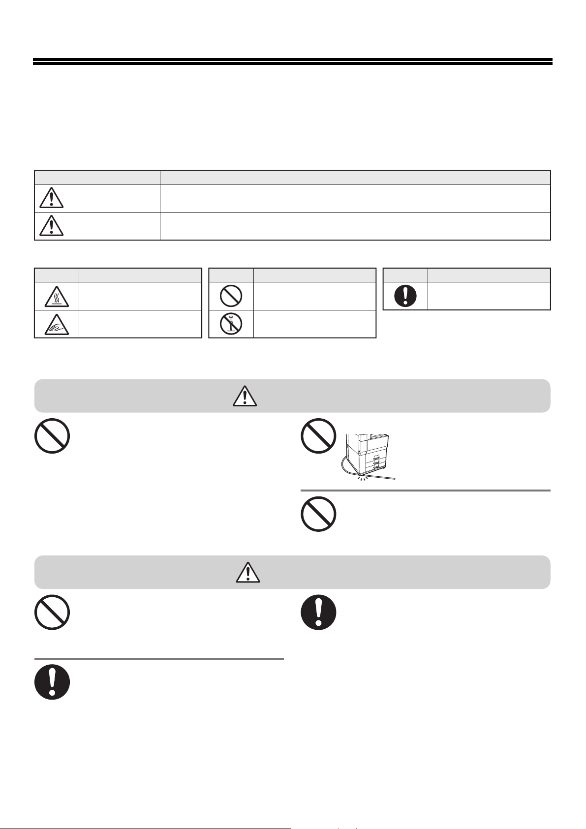
WARNING
Do not damage or modify the power cord.
Do not insert or remove the power plug with wet
hands.
This may cause electrical shock.
Symbol Meaning
MANDATORY ACTIONS
Placing heavy objects on the
power cord, pulling it, or forcibly
bending it will damage the cord,
resulting in fire or electrical
shock.
4
CAUTION
When removing the power plug from the outlet,
do not pull on the cord.
Pulling on the cord may cause damage such as wire
exposure and breakage, and may result in fire or
electrical shock.
If you will not use the machine for a long time,
be sure to remove the power plug from the
outlet for safety.
When moving the machine, switch off the main
power and remove the power plug from the
outlet before moving.
The cord may be damaged, creating a risk of fire or
electrical shock.
Page 7
Installation notes
CAUTIONS
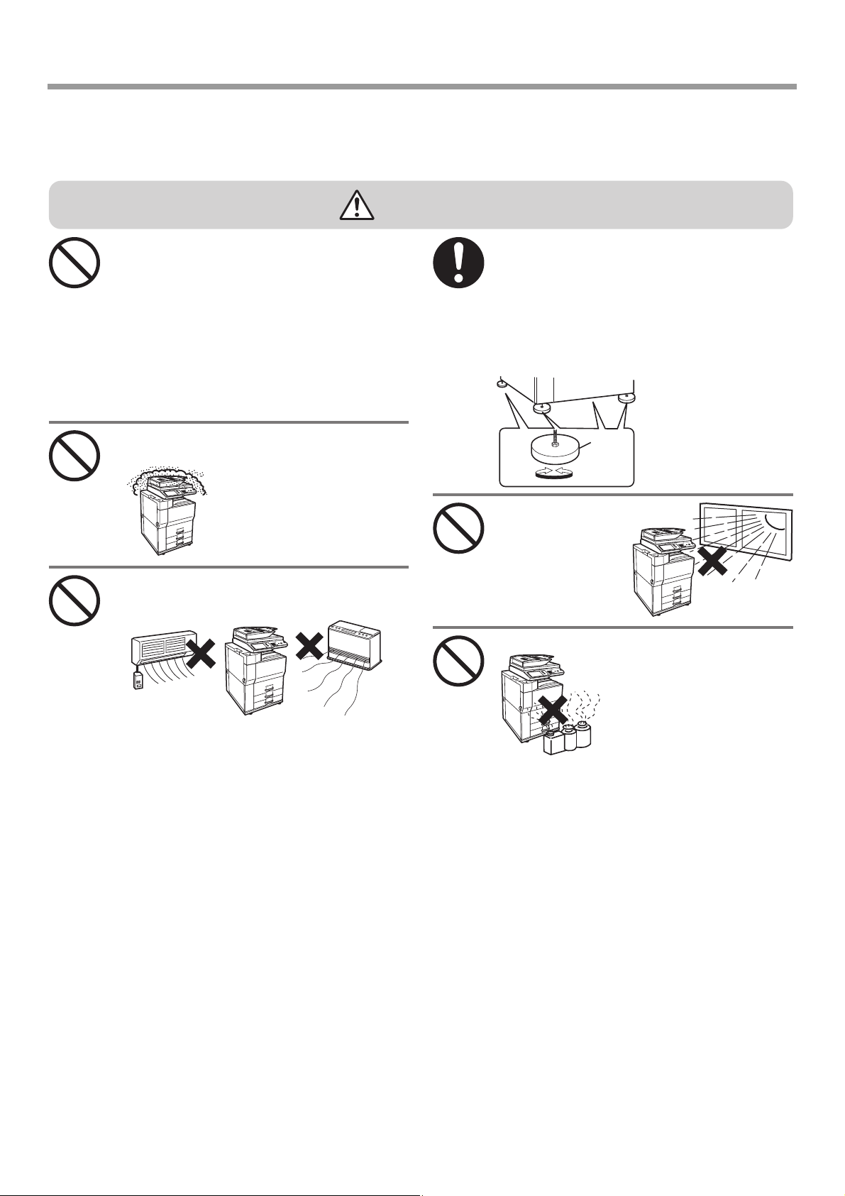
CAUTION
Do not install the machine on an unstable or
slanted surface. Install the machine on a surface
that can withstand the weight of the machine.
Risk of injury due to the machine falling or toppling.
If peripheral devices are to be installed, do not
install on an uneven floor, slanted surface, or
otherwise unstable surface. Danger of slippage,
falling, and toppling. Install the product on a flat,
stable surface that can withstand the weight of the
product. (Weight when various peripheral devices
are installed: approx. 326 kg (718 lbs.))
Do not install in a location with moisture or dust.
Risk of fire and electrical shock.
If dust enters the machine, dirty
output and machine failure may
result.
Locations that are excessively hot, cold, humid,
or dry (near heaters, humidifiers, air
conditioners, etc.)
When the machine is installed, the adjusters (4)
must be lowered to the floor to secure the
machine (prevent it from moving).
Rotate the adjusters in the locking direction until
they are in firm contact with the floor.
If you find it necessary to reposition the
machine due to rearrangement of your office
layout or other reason, retract the adjusters from
the floor, turn off the
power, and then move
the machine.
Adjuster
Lock
Locations exposed to direct
sunlight
Plastic parts may
become deformed
and dirty output may
result.
Locations with ammonia gas
Release
(After moving the
machine, lower the
adjusters again to secure
the machine.)
Installing the machine next to a
diazo copy machine may cause
dirty output.
The paper will become damp and condensation may
form inside the machine, causing misfeeds and dirty
output.
Ambient environment (page 47)
☞
If the location has an ultrasonic humidifier, use pure
water for humidifiers in the humidifier. If tap water is
used, minerals and other impurities will be emitted,
causing impurities to collect on the inside of the
machine and create dirty output.
5
Page 8
CAUTIONS
Installation notes (continued)
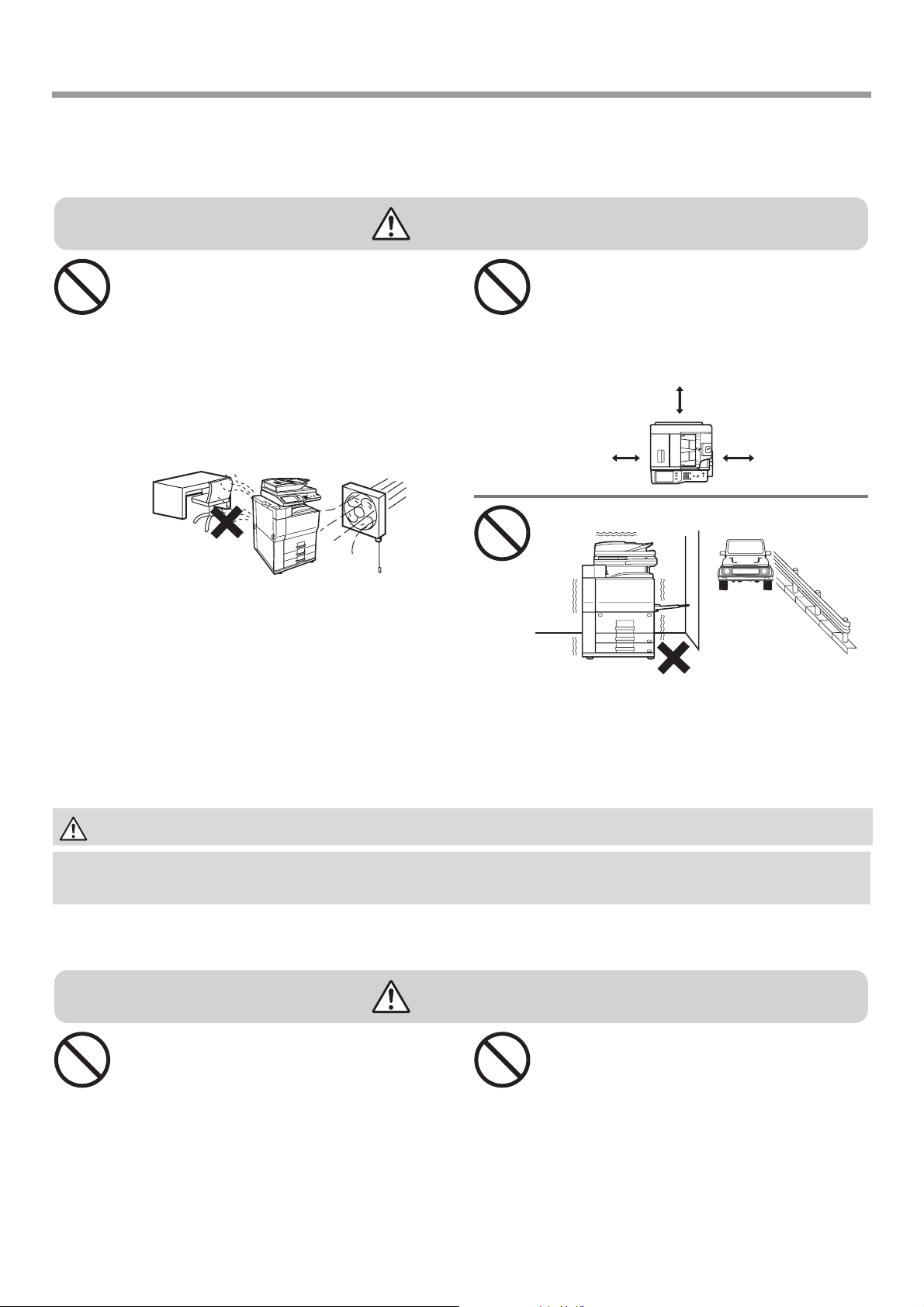
CAUTION
Do not install the machine in a location with
poor ventilation. Install so that exhaust from the
machine does not directly contact people.
A small amount of ozone is produced within the
printer during operation. The emission level is
insufficient to cause any health hazard.
The present recommended long term exposure limit
for ozone is 0.1 ppm (0.2 mg/m
hr. time-weighted average concentration.
However, since the small amount that is emitted
may have an objectionable odor, it is advisable to
place the copier in a ventilated area.
A small amount of ozone is created inside the
machine during printing. The amount of ozone
created is not sufficient to be harmful; however, an
unpleasant odor may be noticed during large copy
runs, and thus the machine should be installed in a
room with a ventilation fan or windows that provide
sufficient air circulation. (The odor may occasionally
cause headaches.)
* Install the machine so that people are not directly
exposed to exhaust from the machine. If installed
near a window, ensure that the machine is not
exposed to direct sunlight.
3
) calculated as an 8
Near a wall
Be sure to allow the required space around the
machine for servicing and proper ventilation. (The
machine should be no closer than the distances
indicated below from walls. The indicated distances
are for the case when a saddle finisher and large
capacity paper tray are not installed.)
30cm
(11-13/16")
30cm
(11-13/16")
Locations subject to vibration.
Vibration may cause failure.
45cm
(17-23/32")
The machine includes a built-in hard drive. Do not subject the machine to shock or vibration. In particular, never
move the machine while the power is on.
• The machine should be installed near an accessible power outlet for easy connection.
• Connect the machine to a power outlet which is not used for other electric appliances. If a lighting fixture is connected to the
same outlet, the light may flicker.
About consumables
CAUTION
Do not throw a toner cartridge into a fire.
Toner may fly and cause burns.
6
Store a toner cartridge out of the reach of
children.
Page 9
Handling precautions
CAUTIONS
WARNING
Do not place a container of water or other liquid,
or a metal object that might fall inside, on the
machine.
If the liquid spills or the object
falls into the machine, fire or
electrical shock may result.
Do not remove the machine casing.
High-voltage parts inside the machine may cause
electrical shock.
Do not make any modifications to this machine.
Doing so may result in personal injury or damage to
the machine.
Do not use a flammable spray to clean the
machine.
If gas from the spray comes in contact with hot
electrical components or the fusing unit inside the
machine, fire or electrical shock may result.
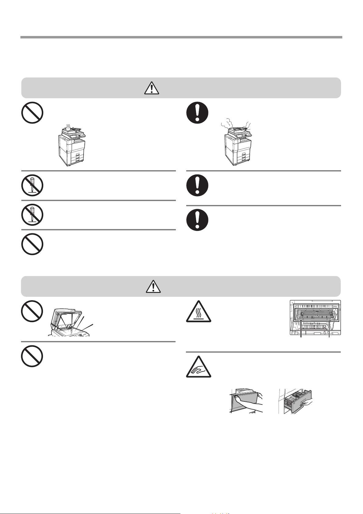
If you notice smoke, a strange odor, or other
abnormality, do not use the machine.
If used in this condition, fire or
electrical shock may result.
Immediately switch off the main
power and remove the power
plug from the power outlet.
Contact your dealer or nearest
authorised service
representative.
If a thunder storm begins, switch off the main
power and remove the power plug from the
outlet to prevent electrical shock and fire due to
lightning.
If a piece of metal or water enters the machine,
switch off the main power and remove the power
plug from the power outlet.
Contact your dealer or nearest authorised service
representative. Using the machine in this condition
may result in electrical shock or fire.
CAUTION
Do not look directly at the light source.
Doing so may damage your
eyes.
Do not block the ventilation ports on the
hine. Do not install the machine in a
mac
location that will block the ventilation ports.
Blocking the ventilation ports will cause heat to build
up in the machine, creating a risk of fire.
The machine includes the document filing function, which stores document image data on the machine's hard drive. Stored
documents can be called up and printed or transmitted as needed. If a hard drive failure occurs, it will no longer be possible to call
up the stored document data. To prevent the loss of important documents in the unlikely event of a hard drive failure, keep the
originals of important documents or store the original data elsewhere.
With the exception of instances provided for by law, Sharp Corporation bears no responsibility for any damages or loss due to the
loss of stored document data.
The fusing unit and paper
exit area are hot. When
removing a misfeed, do not
touch the fusing unit and
paper exit area. Take care
not to burn yourself.
When loading paper, removing a misfeed,
performing maintenance, closing the front and
side covers, and inserting and removing trays,
take care that your fingers are not pinched.
F
using
unit
Paper
exit area
7
Page 10
CAUTIONS
Laser information
Wave length 790 nm ± 10 nm
Pulse times
(North America and Europe)
Output power Max 0.5 mW (LD1+ LD2)
Caution
Use of controls or adjustments or performance of procedures other than those specified herein may result in hazardous radiation exposure.
This Digital Equipment is CLASS 1 LASER PRODUCT (IEC 60825-1 Edition 1.2-2001)
This Digital Equipment is rated Class 1 and complies with 21 CFR 1040.10 and 1040.11 of the CDRH standards. This means that
the equipment does not produce hazardous laser radiation. For your safety, observe the precautions below.
• Do not remove the cabinet, operation panel or any other covers.
• The equipment's exterior covers contain several safety interlock switches. Do not bypass any safety interlock by inserting wedges
or other items into switch slots.
MX-M623U: 3.3 µs ± 6.4 ns /7 mm
MX-M753U (Heavy paper mode): 3.3 µs ± 6.4 ns /7 mm
MX-M753U (Standard mode): 2.8 µs ± 5.4 ns /7 mm
SAFETY PRECAUTIONS
"BATTERY DISPOSAL"
THIS PRODUCT CONTAINS A LITHIUM PRIMARY MEMORY BACK-UP BATTERY THAT MUST BE DISPOSED OF PROPERLY.
PLEASE CONTACT YOUR LOCAL SHARP DEALER OR AUTHORISED SERVICE REPRESENTATIVE FOR ASSISTANCE IN
DISPOSING OF THIS BATTERY.
Each instruction also covers the optional units used with these products.
8
Page 11
OPERATION MANUALS AND HOW TO USE THEM
Printed manuals and a manual in PDF format are provided with the machine.
Printed manuals
This section explains precautions to ensure safe usage, part names and functions, basic software installation, how to
resolve paper jams, and daily maintenance procedures. Refer to the PDF instruction manual for instructions on how to
use the machine.
Start Guide
(this manual)
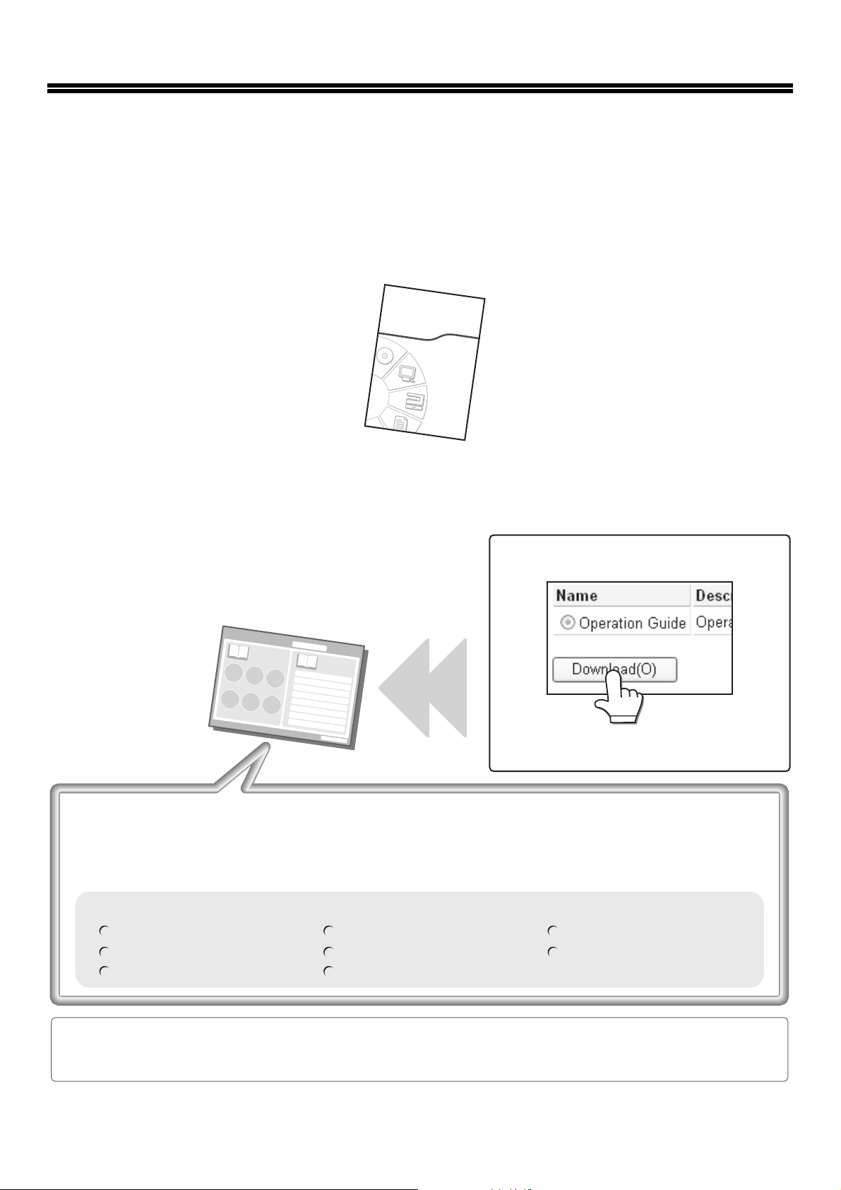
Manuals in PDF format
The explanation of the functions that can be used on the machine are provided in the Operation Guide in PDF format.
The Operation Guide can be downloaded from the Web pages in the machine.
Download the Operation Guide from the Web
pages in the machine.
Operation Guide
For the downloading procedure, see
"Downloading the Operation Guide" (page 11).
Convenient methods for using the Operation Guide
The first page contains a regular table of contents as well as an "I want to..." table of contents.
"I want to..." lets you jump to an explanation based on what you want to do. For example, "I use the copier
function often, so I'd like to save paper".
Use either table of contents as appropriate based on what you want to know.
The contents of the Operation Guide are as follows:
BEFORE USING THE MACHINE
COPIER
PRINTER
FACSIMILE
SCANNER / INTERNET FAX
DOCUMENT FILING
SYSTEM SETTINGS
TROUBLESHOOTING
* To view the Operation Guide in PDF format, Adobe® Reader® or Acrobat® Reader® of Adobe Systems
Incorporated is required. Adobe
http://www.adobe.com/
®
Reader® can be downloaded from the following URL:
9
Page 12
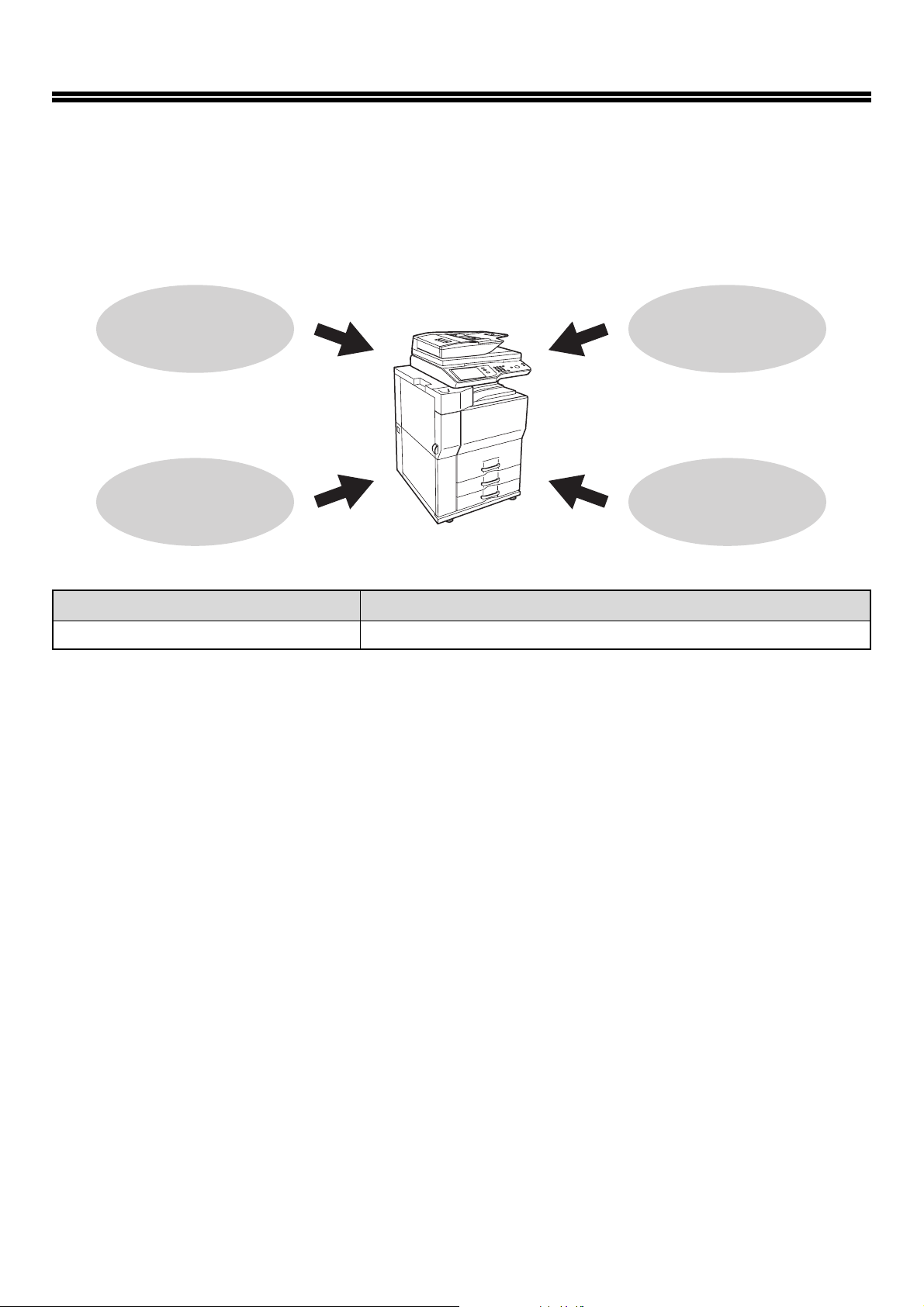
DIGITAL MULTIFUNCTIONAL SYSTEM
FUNCTIONS
This machine provides four major areas of functionality.
Refer to the Operation Guide for details on using the various functions within each area.
Copy
Printer
Model name Function
MX-M623U/MX-M753U Copy, Printer*1, Facsimile*2, Scanner
*1 The printer expansion kit is required.
*2 The facsimile expansion kit is required.
*3 The network scanner expansion kit is required.
Facsimile
Scanner
*3
10
Page 13
ACCESSING THE WEB SERVER IN THE MACHINE
When the machine is connected to a network, the machine's built-in Web server can be accessed from a Web browser
on your computer.
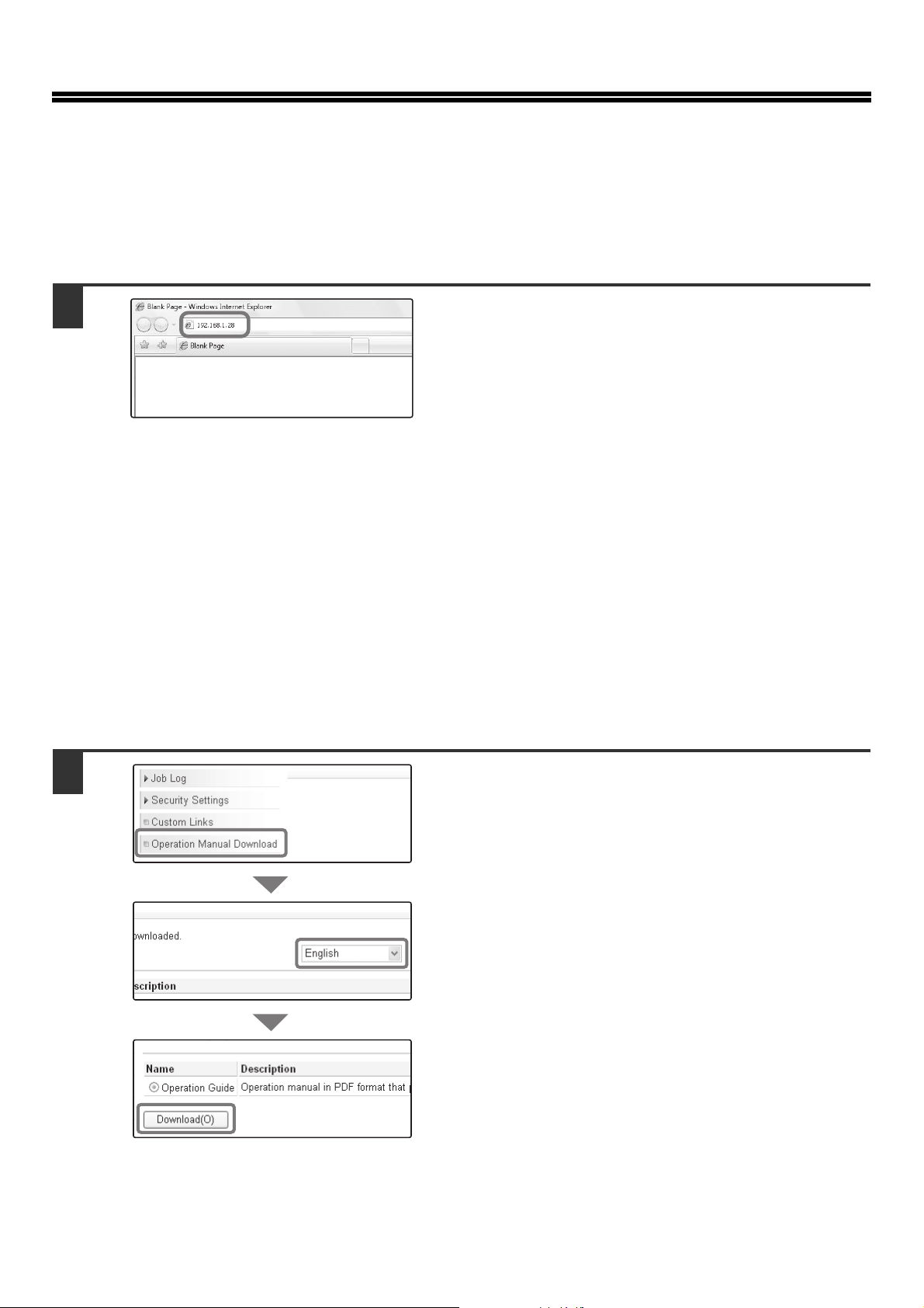
Opening the Web pages
1
Access the Web server in the machine to
open the Web pages.
Start a Web browser on a computer that is
connected to the same network as the
machine and enter the IP address of the
machine.
Recommended Web browsers
Internet Explorer: 6.0 or higher (Windows
Netscape Navigator: 9 (Windows
Firefox: 2.0 or higher (Windows
Safari: 1.5 or higher (Macintosh)
The Web page will appear.
The machine settings may require that user authentication
be performed in order to open the Web page. Please ask
the administrator of the machine for the password that is
required for user authentication.
®
®
)
®
)
)
Downloading the Operation Guide
The Operation Guide, which is a more detailed manual, can be downloaded from the machine's Web pages.
1
Downloading the Operation Guide.
(1) Click [Operation Manual Download] in the
menu of the Web page.
(1)
(2) Select the desired language.
(2)
(3) Click the [Download] button.
The Operation Guide is downloaded.
(3)
11
Page 14
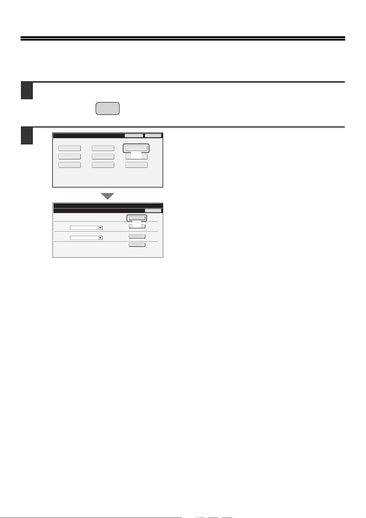
CHECKING THE IP ADDRESS
To check the IP address of the machine, print out the all custom setting list in the system settings.
1
2
System Settings
Total Count
Paper Tray
Settings
Printer Condition
Settings
System Settings
List Print (User)
All Custom Setting List:
Printer Test Page:
PCL Symbol Set List
Sending Address List:
Individual List
Document Filling Folder List:
SYSTEM
SETTINGS
Default Settings
Address Control
Document Filing
Control
Admin Password
List Print
(User)
Fax Data
(1)
Receive/Forward
USB-Device Check
Print
(2)
Print
Print
Print
Exit
Back
Press the [SYSTEM SETTINGS] key.
Select the all custom setting list in the touch
panel.
(1) Touch the [List Print (User)] key.
(2) Touch the [Print] key to the right of "All
Custom Setting List".
The IP address is shown in the list that is printed.
12
Page 15
PART NAMES AND FUNCTIONS
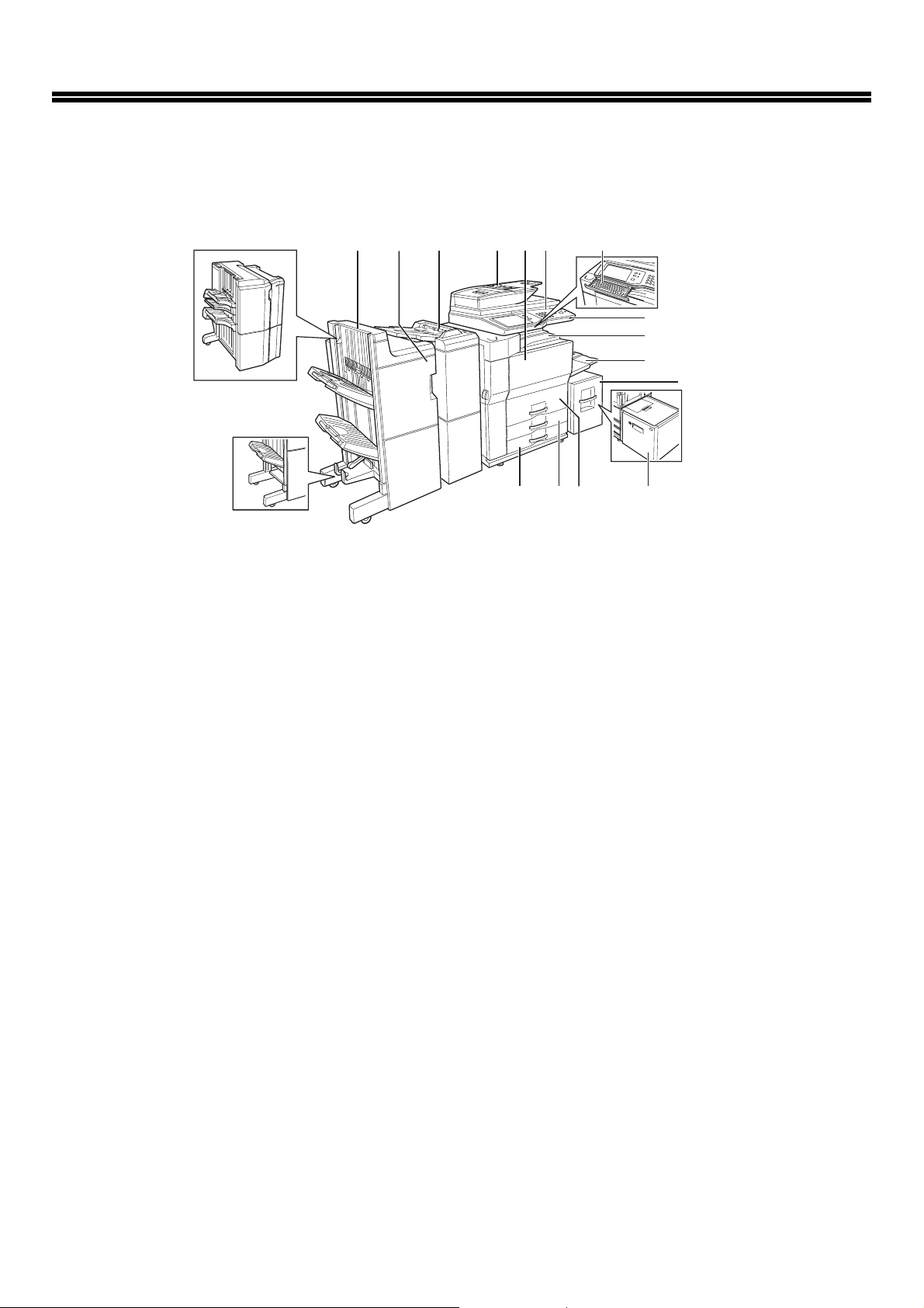
EXTERIOR
(1) (2) (3) (4) (5) (7)(6)
(8)
(9)
(10)
(12)(13)(14)(15)
(11)
(1) Saddle stitch finisher (MX-FN16)
Output device that enables the use of the staple
function and offset function.
Finisher (MX-FN15)
Output device that enables use of the staple
function, offset function and pamphlet copy function.
Finisher (3 trays) (MX-FN14)
Output device that enables use of the staple function
for up to 100 sheets (8-1/2" x 11" size paper).
(2)
Punch module (AR-PN4A, AR-PN4C, AR-PN4D,)
Punches holes in copies and other output.
Requires finisher (MX-FN15) or saddle stitch
finisher (MX-FN16).
Punch module (MX-PN10A, MX-PN10C, MX-PN10D,)
Punches holes in copies and other output.
Requires finisher (3 trays) (MX-FN14).
(3) Inserter (MX-CF10)
Paper set in an inserter can be inserted into
output as covers or inserts. The inserter can be
used to staple output and punch holes manually.
(4) Automatic document feeder
This automatically feeds and scans multiple sheet
originals. Both sides of two-sided originals can be
scanned at once.
(5) Front cover
Open to replace toner cartridge.
(6) Operation panel
This is used to select functions and enter the
number of copies.
(7) Keyboard
This is a keyboard that is incorporated into the
machine. When not used, it can be stored under
the operation panel.
* Peripheral device. For more information, see "PERIPHERAL DEVICES" in "1. BEFORE USING THE MACHINE" in the
Operation Guide.
*
*
*
*
*
*
(8) USB connector (A type)
Supports USB 2.0 (Hi-Speed).
This is used to connect a USB device such as
USB memory to the machine.
For the USB cable, use a shielded cable.
(9) Centre tray
Finished sheets are deposited here.
(10) Bypass tray
Special papers (including transparency film) and
copy paper can be fed from the bypass tray.
(11) Tray 5 (when A4 large capacity tray is
installed) (MX-LC10)*
This holds paper.
(12) Tray 5 (when A3 large capacity tray is
installed) (MX-LCX3N)*
This holds paper.
(13) Tray 1-Tray 2
The trays hold paper. Approximately 800 sheets of
standard A4 or 8-1/2" x 11" size paper (80
lbs.)) can be loaded in tray 1, and approximately
1200 sheets of standard A4 or 8-1/2" x 11" size
paper (80
(14) Tray 3
Tray 3 holds paper. Approximately 500 sheets of
standard (80 g/m
in this tray. Tabbed paper and transparencies can
also be loaded.
(15) Tray 4
Tray 4 holds paper. Approximately 500 sheets of
standard (80 g/m
in this tray.
g
/m2 (20 lbs.)) can be loaded in tray 2.
2
(20 lbs.)) paper can be loaded
2
(20 lbs.)) paper can be loaded
g
/m2 (20
13
Page 16
PART NAMES AND FUNCTIONS
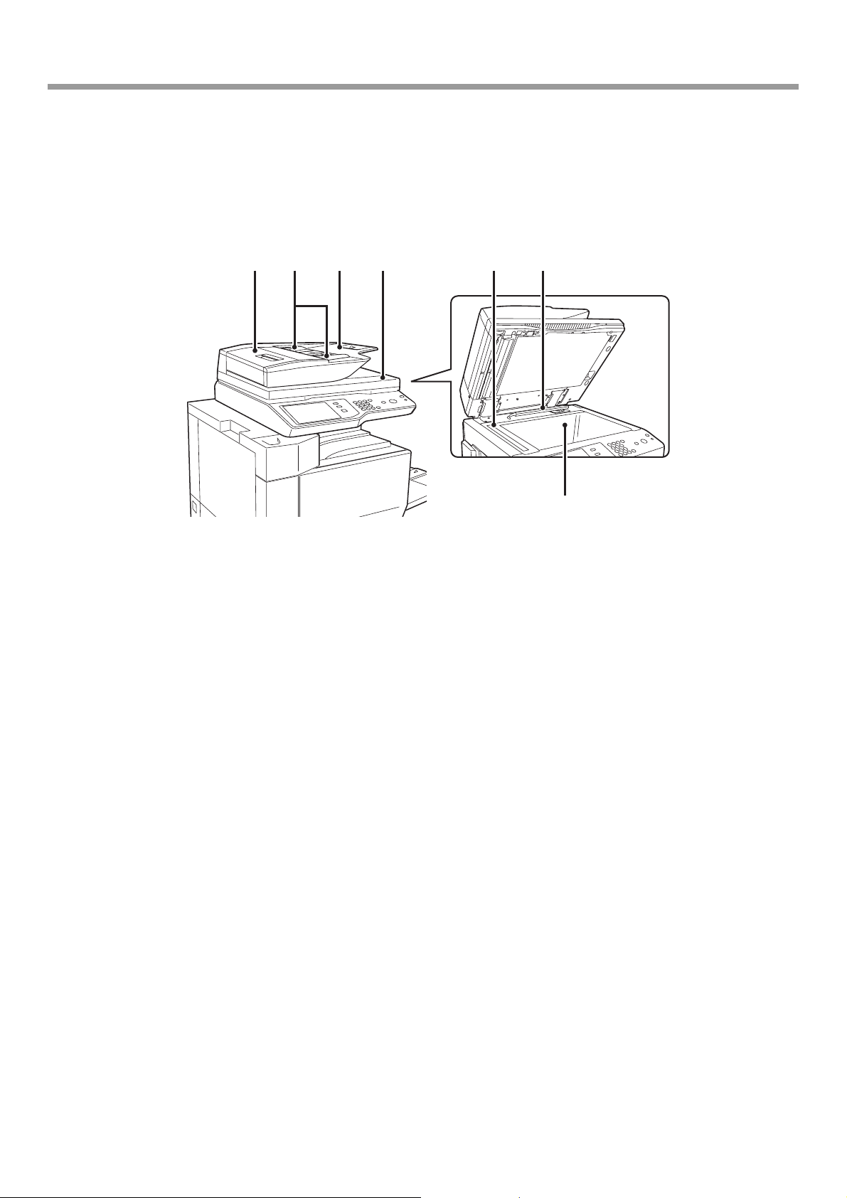
AUTOMATIC DOCUMENT FEEDER AND DOCUMENT
GLASS
(5) (6)(1) (2) (3) (4)
(1) Document feeding area cover
Open this cover to remove an original misfeed or clean
the paper feed roller.
(2) Original guides
These help ensure that the original is scanned correctly.
Adjust the guides to the width of the original.
(3) Document feeder tray
Place originals in this tray. 1-sided originals must be
placed face up.
(4) Original exit tray
Originals are delivered to this tray after scanning.
(7)
(5) Scanning area
Originals placed in the document feeder tray are scanned
here.
(6) Original size detector
This detects the size of an original placed on the
document glass.
(7) Document glass
Use this to scan a book or other thick original that cannot
be fed through the automatic document feeder.
14
Page 17
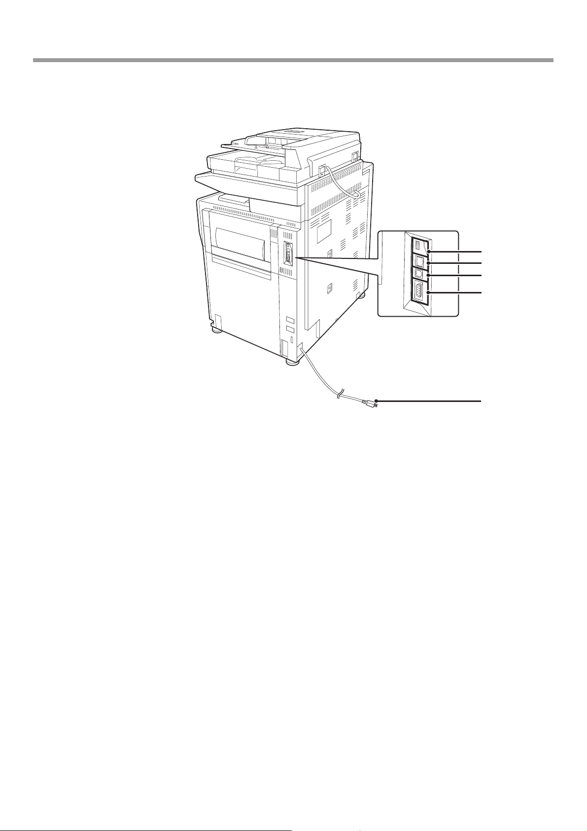
SIDE AND BACK
PART NAMES AND FUNCTIONS
(1)
(2)
(3)
(4)
(1) USB connector (A type)
Supports USB 2.0 (Hi-Speed).
This is used to connect a USB device such as
USB memory to the machine.
(2) LAN connector
Connect the LAN cable to this connector when the
machine is used on a network.
For the LAN cable, use a shielded type cable.
(5)
(3) USB connector (B type)
Supports USB 2.0 (Hi-Speed).
A computer can be connected to this connector to
use the machine as a printer.
For the USB cable, use a shielded cable.
(4) Service-only connector
(5) Power plug
15
Page 18
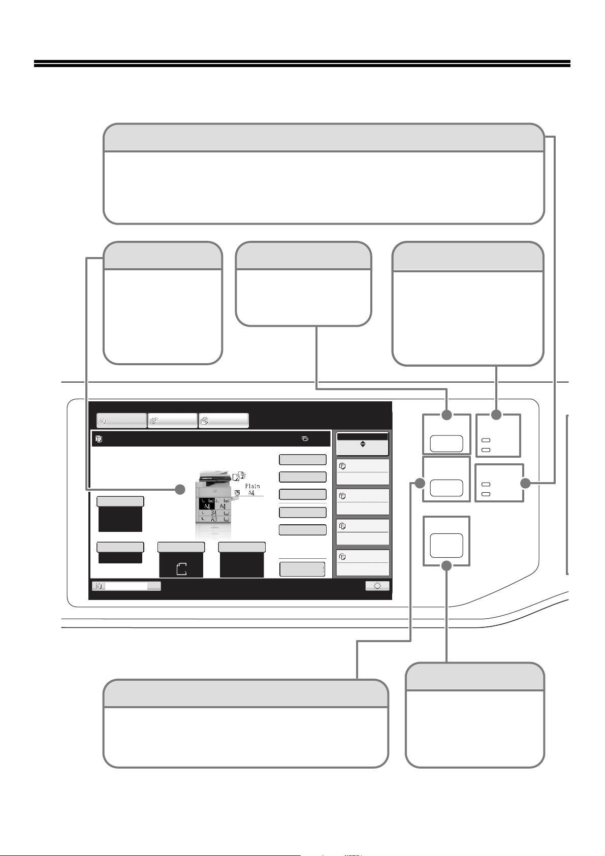
OPERATION PANEL
Image send indicators
LINE indicator
This lights up during transmission or reception in fax mode. The indicator also lights up during transmission in scan mode.
DATA indicator
When a received fax cannot be printed because of a problem such as out of paper, the indicator blinks.
The indicator lights steadily when there is data that is waiting to be transmitted.
Touch panel
Messages and keys
appear in the LCD
display.
Operations are
performed by touching
the keys with your
fingers.
COPY
Ready to scan for copy.
Exposure
Auto
Copy Ratio
100%
Tray1
IMAGE SEND
Original
Auto
[JOB STATUS] key
Press this key to view the job
status screen. You can check
the status of jobs and cancel
jobs in the job status screen.
Print mode indicators
READY indicator
Print data can be received when
this indicator is lit.
DATA indicator
This blinks while print data is
being received and lights steadily
while printing is taking place.
DOCUMENT
FILING
Job Status
0
Special Modes
2-Sided Copy
Output
File
Quick File
Paper Select
Auto
A4
A4
Plain
Preview
MFP Status
020/015
Copying
005/000
Waiting
010/000
Waiting
010/000
Waiting
JOB STATUS
SYSTEM
SETTINGS
HOME
PRINT
READY
DATA
IMAGE SEND
LINE
DATA
16
[SYSTEM SETTINGS] key
Press this key to display the system settings screen. The system
settings can be adjusted to make the machine easier to use, such
as configuring paper tray settings and storing addresses.
[HOME] key
To uch this key to display the
home screen.
Keys of frequently used functions
can be registered in this screen
for quick access, making the
machine easier to use.
Page 19

Numeric keys
Numeric keys
These are used to enter the number of
These are used to enter the number of
copies, fax numbers, and other
copies, fax numbers, and other
numbers.
numbers.
[LOGOUT] key ( )
[LOGOUT] key ( )
When user authentication is enabled,
When user authentication is enabled,
press this key to log out after using
press this key to log out after using
the machine. When using the fax
the machine. When using the fax
function, this key can be pressed to
function, this key can be pressed to
send tone signals on a pulse dial line.
send tone signals on a pulse dial line.
[#/P] key ( )
[#/P] key ( )
Press this key to use a job program
Press this key to use a job program
when using the copier function. When
when using the copier function. When
using the fax function, press this key
using the fax function, press this key
to dial using a program.
to dial using a program.
[CLEAR] key
[CLEAR] key
Press this key to return
Press this key to return
settings such as the number
settings such as the number
of copies to "0".
of copies to "0".
[START] key
Use this key to copy or scan an
original. This key is also used to
send a fax in fax mode.
OPERATION PANEL
Main power indicator
Main power indicator
This indicator lights when the
This indicator lights when the
main power is switched on.
main power is switched on.
[POWER] key
[POWER] key
Use this key to turn the
Use this key to turn the
machine power on and
machine power on and
off.
off.
LOGOUT
[CLEAR ALL] key
[CLEAR ALL] key
Press this key to redo an operation from
Press this key to redo an operation from
the beginning.
the beginning.
All settings will be cleared and operation
All settings will be cleared and operation
will return to the initial state.
will return to the initial state.
[STOP] key
[STOP] key
Press this key to stop a copy job or scanning of
Press this key to stop a copy job or scanning of
an original.
an original.
[POWER SAVE] key
[POWER SAVE] key
Use this key to activate power save mode. The
Use this key to activate power save mode. The
[POWER SAVE] key blinks when the machine is in
[POWER SAVE] key blinks when the machine is in
power save mode. This key is also used to
power save mode. This key is also used to
deactivate power save mode.
deactivate power save mode.
17
Page 20

TURNING THE POWER ON AND OFF
The machine has two power switches. The main power switch is at the top right after the front cover is opened. The
other power switch is the [POWER] key ( ) on the operation panel at the top right.
Main power switch
When the main power switch is switched on, the main
power indicator on the operation panel lights up.
"On"
position
"Off" position
Turning on the power
(1) Switch the main power switch to the "on"
position.
(2) Press the [POWER] key ( ) to turn on the
power.
[POWER] key
Main power indicator
[POWER] key
Turning off the power
(1) Press the [POWER] key ( ) to turn off the
power.
(2) Switch the main power switch to the "off"
position.
• Before switching off the main power switch, make sure that the DATA indicator for printing and the DATA and
LINE indicators for image send are not lit or blinking on the operation panel.
Switching off the main power switch or removing the power cord from the outlet while any of the indicators are lit
or blinking may damage the hard drive and cause data to be lost.
• Switch off both the [POWER] key ( ) and the main power switch and unplug the power cord if you suspect a
machine failure, if there is a bad thunderstorm nearby, or when you are moving the machine.
When using the fax or Internet fax function, always keep the main power switch in the "on" position.
Restarting the machine
In order for some settings to take effect, the machine must be restarted.
If a message in the touch panel prompts you to restart the machine, press the [POWER] key ( ) to turn off the power
and then press the key again to turn the power back on.
In some states of the machine, pressing the [POWER] key ( ) to restart will not make the settings take effect. In this case,
use the main power switch to switch the power off and then on.
18
Page 21

PLACING ORIGINALS
The automatic document feeder can be used to automatically scan many originals at once. This saves you the trouble of
manually feeding each original.
For originals that cannot be scanned using the automatic document feeder, such as a book or a document with notes
attached, use the document glass.
Using the automatic document feeder
When using the automatic document feeder, place the originals in the document feeder tray.
Make sure an original has not been placed on the document glass.
Place the originals face up with the edges
aligned evenly.
Adjust the original guides
to the width of the originals.
The indicator line indicates approximately
how many originals can be placed. The placed
originals must not be higher than this line.
Using the document glass
Take care that your fingers are not pinched when closing the automatic document feeder.
After placing the original, be sure to close the automatic document feeder. If left open, parts outside of the original will be
copied black, causing excessive use of toner.
Place the original face down.
Align the top left corner of the
original with the tip of the
mark in the far left corner of the
glass.
Place the original
face down.
To place a thick original such as
a book, push up the far edge of
the automatic document feeder
and then close the automatic
document feeder slowly.
19
Page 22

PLACING ORIGINALS
USEABLE PAPER
Various types of paper are sold. This section explains what plain paper and what special media can be used with the
machine. For detailed information on the sizes and types of paper that can be loaded in each tray of the machine, see
the specifications in this manual and "Paper Tray Settings" (page 7-13) in "7. SYSTEM SETTINGS" of the Operation
Guide.
Plain paper, special media
Plain paper that can be used
• SHARP standard plain paper (80 g/m2 (21 lbs.)). For paper specifications, see the specifications in this manual.
• Pain paper other than SHARP standard paper (60 g/m
• Recycled paper, coloured paper and pre-punched paper must meet the same specifications as plain paper. Contact your dealer or
nearest authorised service representative for advice on using these types of paper.
Types of paper that can be used in each tray
The following types of paper can be loaded in each tray.
2
to 105 g/m2 (16 lbs. to 28 lbs.))
Tray 5
Tray 1/
Tray 2
Plain paper Permitted Permitted Permitted Permitted Permitted Permitted Permitted
Pre-printed Permitted Permitted Permitted Permitted Permitted Permitted Permitted
Recycle Paper Permitted Permitted Permitted Permitted Permitted Permitted Permitted
Letter head Permitted Permitted Permitted Permitted Permitted Permitted Permitted
Pre-punched Permitted Permitted Permitted Permitted Permitted Permitted Permitted
Colour Permitted Permitted Permitted Permitted Permitted Permitted Permitted
Heavy paper
Labels – Permitted – Permitted – – –
Transparency film – Permitted – Permitted – –
Tab paper – Permitted – Permitted – – Permitted
*1 Paper weights of up to 209 g/m2 (110 lbs.) can be used. Paper weights of up to 256 g/m2 (140 lbs.) can be used with the inserter.
*2 Depending on the type of transparency film used, a double feed may occur. In this case, feed one sheet into the tray at a time.
*1
– Permitted Permitted Permitted – – Permitted
Tray 3 Tray 4
Bypass
tray
(A4 large
capacity
tray)
Tray 5
(A3 large
capacity
tray)
Inserter
Permitted
*2
20
Page 23

PLACING ORIGINALS
Print side face up or face down
Paper is loaded with the print side face up or face down depending on the paper type and tray.
Trays 1 to 4
Load the paper with the print side face up.
However, if the paper type is "Letter Head" or "Pre-Printed", load the paper with the print side face down*.
Bypass tray and tray 5
Load the paper with the print side face up.
However, if the paper type is "Letter Head" or "Pre-Printed", load the paper with the print side face down*.
*If "Disabling of Duplex" is enabled in the system settings (administrator), load the paper with the print side face up.
Paper that cannot be used
• Special media for inkjet printers
(fine paper, glossy paper, glossy film, etc.)
• Carbon paper or thermal paper
• Pasted paper
• Paper with clips
• Paper with fold marks
• Torn paper
• Oil-feed transparency film
• Thin paper less than 56 g/m
• Paper that is 210 g/m
2
2
(15 lbs.)
(80 lbs.) or heavier
Non-recommended paper
• Iron-on transfer paper
• Japanese paper
• Perforated paper
• Various types of plain paper and special media are sold. Some types cannot be used with the machine. Contact your dealer
or nearest authorised service representative for advice on using these types of paper.
• The image quality and toner fusibility of paper may change due to ambient conditions, operating conditions, and paper
characteristics, resulting in image quality inferior to that of SHARP standard paper. Contact your dealer or nearest
authorised service representative for advice on using these types of paper.
• The use of non-recommended or prohibited paper may result in skewed feeding, misfeeds, poor toner fusing (the toner
does not adhere to the paper well and can be rubbed off), or machine failure.
• The use of non-recommended paper may result in misfeeds or poor image quality. Before using non-recommended paper,
check if printing can be performed properly.
• Irregularly shaped paper
• Stapled paper
• Damp paper
• Curled paper
• Paper on which either the print side or the reverse side
has been printed on by another printer or multifunction
device.
• Paper with a wave-like pattern due to moisture
absorption
• Envelopes
21
Page 24

LOADING PAPER IN A TRAY
Names of the trays
The names of the trays are shown below.
For the number of sheets of paper that can be loaded in each tray, see the following manuals:
• Operation Guide, "Paper Tray Settings" in "7. SYSTEM SETTINGS"
• Start Guide (this manual), "SPECIFICATIONS"
(1) Tray 1
(2) Tray 2
(3) Tray 3
(6)
(1)
(2)
(3)
(4)
(4) Tray 4
(5) Tray 5 (when a A4 large capacity
tray is installed)
(5)
(6) Bypass tray
22
Page 25

LOADING PAPER IN A TRAY
Indicator line
Indicator line
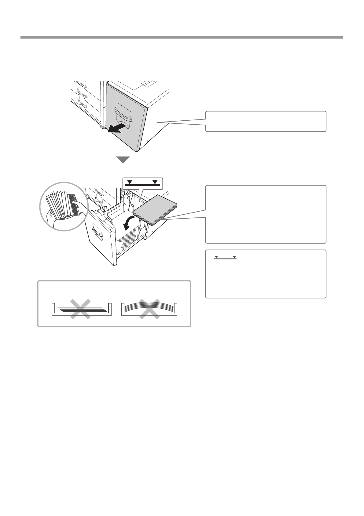
Loading paper in paper tray 1 - tray 2
A4 or 8-1/2" x 11" size paper can be loaded in tray 1 and tray 2. If you wish to change the paper size of tray 1 or tray 2,
see "CHANGING THE PAPER SIZE IN PAPER TRAY 1 - TRAY 2" in the Operation Guide.
Gently pull out the paper tray.
Load paper in the left and right trays.
Insert the paper with the print side face
up.
Fan the paper well before inserting it.
Otherwise, multiple sheets may feed at
once and cause a misfeed.
Insert the paper and then gently push the
tray into the machine.
Indicator line
The indicator line indicates the maximum
height of the paper that can be loaded in
the tray. When loading paper, make sure
that the stack is not higher than the
indicator line.
To load the paper in tray 3 and tray 4, see "TRAY SETTINGS FOR TRAY 1 TO 4" in the Operation Guide.
23
Page 26

LOADING PAPER IN A TRAY
Changing the tray settings
When you change the paper in a tray, the tray settings in the system settings must also be changed.
1
2
System Settings
Total Count
Paper Tray
Settings
Printer Condition
(1)
Settings
System Settings
Paper Tray Settings
Tray Settings
Paper Type Registration
(2)
Auto Tray Switching
Custom Size Registration (Bypass)
SYSTEM
SETTINGS
Default Settings
Address Control
Document Filing
Control
Admin Password
List Print
(User)
Fax Data
Receive/Forward
USB-Device Check
Exit
Back
Press the [SYSTEM SETTINGS] key.
Configure the tray settings in the touch
panel.
(1) Touch the [Paper Tray Settings] key.
(2) Touch the [Tray Settings] key.
Tray Settings
Type
Size
Fixed Paper Side Disable Duplex Disable Staple Disable Punch
Copy Print Fax I-Fax Doc. Filing
System Settings
Tray Settings
Tray:
Type:
Size:
Paper Property:
Tray 3
Plain
A4
Paper Property
Feeding Approved Job
Tray 3
Recycled
Auto-AB
A3,A4,A4R,B4,B5,B5R,
216x330(8 1/2x13)
Print
Copy
I-Fax
Fax
Change
(3)
Cancel
(4)
(5)
Back
(6)
(3) Touch the [Change] key in "Tray 3".
OK
(4) Select [Recycled] from the "Type" select
box.
(5) Make sure that [Auto-AB] is selected in the
"Size" select box.
For more information, see "Paper Tray Settings" in
"7. SYSTEM SETTINGS" in the Operation Guide.
(6) Touch the [OK] key.
The above steps change the paper settings for tray 3 to A4
recycled paper.
24
Page 27

Loading paper in other trays
Bypass tray
When loading A3 or B4 size paper, pull out the tray
extension.
The maximum number of sheets that can be loaded
in the bypass tray is approximately 100 for plain
paper.
LOADING PAPER IN A TRAY
The side to be
copied on must
be face up!
Place paper that is A5 (7-1/4" x 10-1/2") or smaller
in the horizontal orientation.
Special types of paper that cannot be loaded in other trays can be loaded in the bypass tray.
For detailed information on the bypass tray, see "LOADING PAPER IN THE BYPASS TRAY" in "1. BEFORE
USING THE MACHINE" in the Operation Guide.
25
Page 28
LOADING PAPER IN A TRAY
A4 large capacity tray
The paper size of tray 5 can only be changed by a service technician.
Gently pull out the paper tray.
Insert the paper with the print side face
up.
Fan the paper well before inserting it.
Otherwise, multiple sheets may feed at
once and cause a misfeed.
Insert the paper and then gently push the
tray into the machine.
Do not load as shown below.
Indicator line
The indicator line indicates the maximum
height of the paper that can be loaded in
the tray. When loading paper, make sure
that the stack is not higher than the
indicator line.
26
Page 29

LOADING PAPER IN A TRAY
A3 large capacity tray
To change the paper size of tray 5, see "TRAY SETTINGS OF TRAY 5 (A4 LARGE CAPACITY TRAY)" in the Operation
Guide.
Press the operation button and wait until
the operation button indicator turns off.
Gently pull out the paper tray.
Do not load as shown below.
Insert the paper with the print side face
up.
Fan the paper well before inserting it.
Otherwise, multiple sheets may feed at
once and cause a misfeed.
Insert the paper and then gently push the
tray into the machine.
Indicator line
The indicator line indicates the maximum
height of the paper that can be loaded in
the tray. When loading paper, make sure
that the stack is not higher than the
indicator line.
27
Page 30

BEFORE INSTALLING THE SOFTWARE
This chapter describes the software programs that allow you to use the printer and scanner functions of the machine,
the CD-ROMs that contain the software, and the pages where the basic installation procedures can be found.
For details on installation procedures, refer to Chapter 1 of the Operation Guide.
CD-ROMS AND SOFTWARE
The software that can be used with the machine is on the CD-ROMs that accompany the machine and the expansion kits.
Before installing the software, make sure that your computer and the machine meet the system requirements described in
"VERIFYING SYSTEM REQUIREMENTS" (page 30).
SOFTWARE CD-ROM
The "Software CD-ROM" that accompanies the machine contains the printer driver and other software. The "Software
CD-ROM" consists of 2 discs.
• The CD-ROM does not include software for Mac OS 9.0 to 9.2.2/X10.2.8/X10.3.9.
Contact your dealer or nearest authorised service representative if you want software for Mac OS 9.0 to
9.2.2/X10.2.8/X10.3.9.
• The CD-ROM does not include printer driver for PCL5e. Contact your dealer or nearest authorised service representative if
you want printer driver for PCL5e.
Disc 1
Software for Windows
• Printer driver
These allow the machine to be used as a printer.
- PCL6 printer driver
The machine supports the Hewlett-Packard PCL6 printer control languages.
- PS printer driver
The PS printer driver supports the PostScript 3 page description language developed by Adobe Systems
Incorporated.
- PPD driver
The PPD driver enables the machine to use the standard Windows PS printer driver.
☞ WHEN THE MACHINE IS CONNECTED TO A NETWORK (page 34)
☞ WHEN THE MACHINE WILL BE CONNECTED WITH A USB CABLE (page 1-91 in the Operation Guide)
• Printer Status Monitor (can only be used when the machine is connected to a network)
This allows you to monitor the status of the machine on your computer screen.
☞ INSTALLING THE PRINTER STATUS MONITOR (page 1-101 in the Operation Guide)
Software for Macintosh
• PPD file
This is the printer description file which enables the machine to be used as a PostScript 3 compatible printer.
The PS3 expansion kit is required to use the machine in a Macintosh environment.
☞ MAC OS X (page 1-109 in the Operation Guide)
☞ MAC OS 9.0 - 9.2.2 (page 1-115 in the Operation Guide)
• The PS3 expansion kit is required to use the machine as a printer in a Macintosh environment. In addition,
the machine must be connected to a network. A USB connection cannot be used.
• The scanner driver and PC-Fax driver cannot be used in a Macintosh environment.
28
Page 31

BEFORE INSTALLING THE SOFTWARE
Disc 2
Software for Windows
• PC-Fax driver
This enables you to send a file from your computer as a fax using the same procedure as when printing the file.
(When the fax option is installed.)
Even if the fax function is not installed, the PC-Fax driver can be updated using the CD-ROM in the Internet fax
expansion kit to enable you to send a file from your computer as an Internet fax in the same way as you print a file.
☞ INSTALLING THE PRINTER DRIVER / PC-FAX DRIVER (page 34)
The following software can be used only when the machine is connected to a network.
• Scanner driver (TWAIN driver)
This allows you to use the scanner function of the machine from a TWAIN-compliant software application.
☞ INSTALLING THE SCANNER DRIVER (page 1-102 in the Operation Guide)
• Printer Administration Utility
This allows the administrator to monitor the machine and configure machine settings from a computer. To install
and use the Printer Administration Utility, see the Readme file and the manual in PDF format on the "Software
CD-ROM" (Disc 2). The Readme file and manual are in the following folder on the CD-ROM. (Substitute the
letter of your CD-ROM drive for "R" in the following path.)
R:\Sadmin\Documents\English
OTHER CD-ROMS
X "PRINTER UTILITIES" CD-ROM that accompanies the PS3 expansion kit
(for Windows/Macintosh)
This contains the display fonts that are used with the PS printer driver.
(Install the PS printer driver and Macintosh PPD file from the "Software CD-ROM".)
☞ INSTALLING THE PS DISPLAY FONTS (page 1-104 in the Operation Guide)
X "PRINTER UTILITIES" CD-ROM that accompanies the Internet fax
expansion kit (for Windows)
This CD-ROM is used to update the PC-Fax driver on the "Software CD-ROM" so that it can be used to send
Internet faxes (PC-I-Fax function).
If you wish to use the PC-I-Fax function, first install the PC-Fax driver from the "Software CD-ROM" and then run the
installer on this CD-ROM. If the PC-Fax driver is already installed, run only the installer. (There is no need to reinstall
the PC-Fax driver.)
☞ INSTALLING THE PRINTER DRIVER / PC-FAX DRIVER (page 34)
29
Page 32

BEFORE INSTALLING THE SOFTWARE
VERIFYING SYSTEM REQUIREMENTS
SYSTEM REQUIREMENTS
Before installing the software described in this manual, make sure that your computer satisfies the following
requirements.
Windows*
Operating system Windows 2000 Professional, Windows XP Professional*2,
Windows XP Home Edition, Windows 2000 Server,
Windows Server 2003
*2
2008
, WIndows 7
Computer type IBM PC/AT compatible computer
Equipped with a 10Base-T/100Base-TX/1000Base-T LAN
board or equipped standard with a USB 2.0
Display 1024 x 768 dots resolution and 16-bit colour or higher is
recommended.
Other hardware
requirements
An environment that allows any of the above operating
systems to fully operate.
*2
, Windows Vista*2, Windows Server
*2*3
1
*4
/1.1*5 port.
Macintosh*
Mac OS 9.0 to 9.2.2,
Mac OS X v10.2.8,
Mac OS X v10.3.9,
Mac OS X v10.4.11,
Mac OS X v10.5 to 10.5.8,
Mac OS X v10.6 to 10.6.1
An environment in which any
of the operating systems
listed above can fully operate
(including Macintosh
computers with an Intel
processor).
6
*1 The PCL5e printer driver will not run on any of the 64-bit editions of the Windows operating systems, Windows
Server 2008, and Windows 7.
*2 Includes the 64-bit edition.
*3 Printer Administration Utility 4.2 is not compatible with Windows 7.
*4 The machine's USB 2.0 port will transfer data at the speed specified by the USB 2.0 (Hi-Speed) standard only if the
Microsoft USB 2.0 driver is preinstalled in the computer, or if the USB 2.0 driver for Windows 2000
Professional/XP/Vista that Microsoft provides through "Windows Update" is installed.
*5 Compatible with models preinstalled with Windows 2000 Professional, Windows XP Professional, Windows XP
Home Edition, Windows 2000 Server, Windows Server 2003, Windows Vista, Windows Server 2008 or Windows 7,
and which are equipped standard with a USB interface.
*6 Cannot be used when the machine is connected with a USB cable. The PC-Fax driver and scanner driver cannot be
used.
30
• For users of Mac OS 9.0 to 9.2.2/X10.2.8/X10.3.9
The CD-ROM does not include software for Mac OS 9.0 to 9.2.2/X10.2.8/X10.3.9
Contact your dealer or nearest authorised service representative if you want software.
• For users of Windows 2000/XP/Server 2003/Vista/Server 2008/7
To perform the procedures described in this manual such as installing the software and configuring settings after
installation, administrator authority is required.
Page 33

BEFORE INSTALLING THE SOFTWARE
SOFTWARE REQUIREMENTS
The following requirements must be met to use the software described in this manual.
Operating
system
environment*
1
Software Required expansion kits Type of connection*
1
Windows PCL6 printer driver,
PCL5e printer driver
PS printer driver,
PPD driver
PC-Fax driver*
Scanner driver Network scanner expansion kit
Printer Status Monitor
Printer Administration Utility
Macintosh Macintosh PPD file
2
Printer expansion kit
Printer expansion kit
PS3 expansion kit
Facsimile expansion kit*
Printer expansion kit
Printer expansion kit
PS3 expansion kit
3
Network/ USB
Network only*4 (cannot be
used with a USB connection)
*1For the types of computers and operating systems that can run the software, see "SYSTEM REQUIREMENTS" (page 30).
*2To use the PC-Fax driver, Internet Explorer 4.0 or later must be installed on your computer.
3
*
When the Internet fax expansion kit is installed, the PC-Fax driver can be updated using the "PRINTER UTILITIES"
CD-ROM to enable the driver to be used as a PC-I-Fax driver. In this case, the driver can be used without the
facsimile expansion kit.
4
*
The scanner driver, Printer Status Monitor, and Printer Administration Utility cannot be used on an IPv6-only network.
31
Page 34

BEFORE INSTALLING THE SOFTWARE
CONNECTING THE MACHINE
CONNECTING TO A NETWORK
To connect the machine to a network, connect the LAN cable to the machine's network connector. Use a shielded LAN
cable.
After connecting the machine to a network, be sure to configure the IP address and other network settings before
installing the software. (The factory default setting for the IP address is to receive the IP address automatically when the
machine is used in a DHCP environment.)
Network settings can be configured using "Network Settings" in the system settings (administrator) on the machine.
• If the machine is used in a DHCP environment, the IP address of the machine may change. If this happens, printing
will not be possible. This problem can be avoided by using a WINS server or by assigning a permanent IP address
to the machine.
• This manual explains how to set up the software in a Windows network environment.
• To use the machine on an IPv6 network, the IPv6 setting must be enabled in "Network Settings" in the system
settings (administrator).
X Checking the IP address of the machine
You can check the IP address of the machine by printing out the "All Custom Setting List" in the system settings. Follow
these steps to print out the "All Custom Setting List".
Press the [SYSTEM SETTINGS] key, touch the [List Print (User)] key, and then touch the [Print] key of "All Custom
Setting List".
CONNECTING THE MACHINE WITH A USB CABLE (Windows)
The machine can be connected to a computer using a USB cable if the computer is a Windows computer. (The USB
interface on the machine cannot be used in a Macintosh environment.)
The machine and computer should be connected while the printer driver is being installed. If a USB cable is connected
before the printer driver is installed, the printer driver will not be installed correctly. For the procedure for connecting a
USB cable, see "WHEN THE MACHINE WILL BE CONNECTED WITH A USB CABLE" (page 1-91 in the Operation
Guide).
32
Page 35

SETUP IN A WINDOWS ENVIRONMENT
This section explains how to install the software on a Windows computer. For more details regarding installation
procedures and instructions for installation in Macintosh environments, see Chapter 1 of the Operation Guide.
OPENING THE SOFTWARE SELECTION SCREEN (FOR
ALL SOFTWARE)
Insert the "Software CD-ROM" into your
1
computer's CD-ROM drive.
• If you are installing the printer driver or printer status
monitor, insert the "Software CD-ROM" that shows
"Disc 1" on the front of the CD-ROM.
• If you are installing the PC-Fax driver or scanner
driver, insert the "Software CD-ROM" that shows
"Disc 2" on the front of the CD-ROM.
Click the [Start] button ( ), click
2
[Computer], and then double-click the
[CD-ROM] icon ( ).
• In Windows XP/Server 2003, click the [start] button,
click [My Computer], and then double-click the
[CD-ROM] icon.
• In Windows 2000, double-click [My Computer] and
then double-click the [CD-ROM] icon.
Double-click the [Setup] icon ( ).
3
In Windows 7, if a message screen appears asking you
for confirmation, click [Yes].
In Windows Vista/Server 2008, if a message screen
appears asking you for confirmation, click [Allow].
The "SOFTWARE LICENCE" window
4
will appear. Make sure that you
understand the contents of the licence
agreement and then click the [Yes]
button.
You can show the "SOFTWARE LICENCE" in a
different language by selecting the desired language
from the language menu. To install the software in the
selected language, continue the installation with that
language selected.
Read the message in the "Welcome"
5
window and then click the [Next] button.
The software selection screen appears.
6
Before installing the software, be sure to click the
[Display Readme] button and view the detailed
information on the software.
* The above screen appears when using the
"Disc 1" CD-ROM.
For the steps that follow, see the appropriate page below
for the software that you are installing.
INSTALLING THE PRINTER DRIVER / PC-FAX DRIVER
• WHEN THE MACHINE IS CONNECTED TO A
NETWORK
- Standard installation: page 34
- Installation by specifying the machine's address:
page 1-86 in the Operation Guide
- Printing using the IPP function and the SSL
function: page 1-89 in the Operation Guide
• WHEN THE MACHINE WILL BE CONNECTED WITH A
USB CABLE: page 1-91 in the Operation Guide
• USING THE MACHINE AS A SHARED PRINTER: page
1-96 in the Operation Guide
INSTALLING THE PRINTER STATUS MONITOR: page
1-101 in the Operation Guide
INSTALLING THE SCANNER DRIVER: page 1-102 in the
Operation Guide
*
If the machine is being used on an IPv6 network, see
"Installation by specifying the machine's address" (page
1-86 in the Operation Guide).
*
33
Page 36

SETUP IN A WINDOWS ENVIRONMENT
INSTALLING THE PRINTER DRIVER / PC-FAX DRIVER
To install the printer driver or the PC-Fax driver, follow the appropriate procedure in this section depending on whether
the machine is connected to a network or connected by USB cable.
WHEN THE MACHINE WILL BE CONNECTED WITH A USB CABLE (page 1-91 in the Operation Guide)
WHEN THE MACHINE IS CONNECTED TO A NETWORK
This section explains how to install the printer driver and the PC-Fax driver when the machine is connected to a
Windows network (TCP/IP network).
Supported operating systems: Windows 2000
* Administrator's rights are required to install the software.
• The PS3 expansion kit is required to use the PS printer driver or the PPD driver.
• To print to the machine over the Internet using the IPP function when the machine is installed in a remote location, or to
print using the SSL (encrypted communication) function, see "Printing using the IPP function and the SSL function" (page
1-89 in the Operation Guide) and install the printer driver or the PC-Fax driver.
• If the machine is connected to an IPv6-only network
The software cannot be installed by detecting the machine's address from the installer. After installing the software as
explained in "Installation by specifying the machine's address" (page 1-86 in the Operation Guide), change the port as
explained in "Changing to a Standard TCP/IP Port" (page 1-107 in the Operation Guide).
• The installation procedure in this section is for both the printer driver and the PC-Fax driver, although the explanations are
centred on the printer driver.
*
/XP*/Server 2003*/Vista*/Server 2008*/7
*
X Standard installation
When the software selection screen appears in step 6 of "OPENING THE SOFTWARE SELECTION SCREEN (FOR
ALL SOFTWARE)" (page 33), perform the steps below.
Click the [Printer Driver] button.
1
To install the PC-Fax driver, click the [PC-Fax Driver]
button on the "Disc 2" CD-ROM.
34
* The above screen appears when using the
"Disc 1" CD-ROM.
Page 37

Click the [Standard installation] button.
2
When [Custom installation] is selected, you can
change any of the items below. When [Standard
installation] is selected, the installation will take place
as indicated below.
• Machine connection method: LPR Direct Print (Auto
Search)
• Set as default printer:Yes (excluding the PC-Fax
driver)
• Printer driver name: Cannot be changed
• PCL printer display fonts: Installed
If you selected [Custom installation], select [LPR
Direct Print (Auto Search)] and click the [Next] button.
If you selected other than [LPR Direct Print (Auto
Search)], see the following pages in the Operation
Guide:
• LPR Direct Print (Specify Address): page 1-86
• IPP: page 1-89 • Shared printer: page 1-96
• Connected to this computer: page 1-91
SETUP IN A WINDOWS ENVIRONMENT
• If the machine is not found, make sure that the
machine is powered on and that the machine is
connected to the network, and then click the
[Re-search] button.
• You can also click the [Specify condition] button and
search for the machine by entering the machine's
name (host name) or IP address.
☞
Checking the IP address of the machine (page
32)
A confirmation window appears. Check
4
the contents and then click the [Next]
button.
When the printer driver selection
5
window appears, select the printer
driver to be installed and click the [Next]
button.
Click the checkbox of the printer driver to be installed so
that a checkmark ( ) appears.
Printers connected to the network are
3
detected. Select the machine and click
the [Next] button.
• When the PC-Fax driver is being installed, this
screen does not appear. Go to the next step.
• The PS3 expansion kit is required to use the PS
printer driver or the PPD driver.
35
Page 38
SETUP IN A WINDOWS ENVIRONMENT
When you are asked whether or not you
6
want the printer to be your default
printer, make a selection and click the
[Next] button.
If you are installing multiple drivers, select the printer
driver to be used as the default printer.
If you do not wish to set one of the printer drivers as the
default printer, select [No].
If you clicked the [Custom installation] button in step 2,
the following windows will appear.
• Printer name window
If you wish to change the printer name, enter the
desired name and click the [Next] button.
• Window confirming installation of the display
fonts
To install the display fonts for the PCL printer driver,
select [Yes] and click the [Next] button.
• When the PC-Fax driver is being installed, this
screen does not appear. Go to the next step.
• If you are not installing the PCL printer driver (you
are installing the PS printer driver or the PPD
driver), select [No] and click the [Next] button.
Follow the on-screen instructions.
7
Read the message in the window that appears and click
the [Next] button.
Installation begins.
When the installation completed screen
8
appears, click the [OK] button.
Click the [Close] button in the window
9
of step 1.
After the installation, a message prompting you to
restart your computer may appear. If this message
appears, click the [Yes] button to restart your
computer.
This completes the installation.
• After installation, see "CONFIGURING THE PRINTER
DRIVER FOR THE OPTIONS INSTALLED ON THE
MACHINE" (page 1-98 in the Operation Guide) to
configure the printer driver settings.
• If you installed the PS printer driver or the PPD driver,
the PS display fonts can be installed from the
"PRINTER UTILITIES" CD-ROM that accompanies the
PS3 expansion kit. See "INSTALLING THE PS
DISPLAY FONTS" (page 1-104 in the Operation
Guide).
• If you are using the machine as a shared printer, see
"USING THE MACHINE AS A SHARED PRINTER"
(page 1-96 in the Operation Guide) to install the printer
driver on each of the client computers.
• If you are using Windows Vista/Server 2008/7
If a security warning window appears, be sure to click
[Install this driver software anyway].
• If you are using Windows 2000/XP/Server 2003
If a warning message regarding the Windows logo
test or digital signature appears, be sure to click the
[Continue Anyway] or [Yes] button.
36
Page 39
MAINTENANCE
This section explains how to clean the machine and replace the toner cartridges.
REGULAR MAINTENANCE
To ensure that the machine continues to provide top quality performance, periodically clean the machine.
Warning
Do not use a flammable spray to clean the machine. If gas from the spray comes in contact with hot electrical components
or the fusing unit inside the machine, fire or electrical shock may result.
• Do not use thinner, benzene, or similar volatile cleaning agents to clean the machine. These may degrade or discolour the
housing.
• Use a soft cloth to gently wipe off dirt from the area on the operation panel with a
mirror-like finish (shown at right). If you use a stiff cloth or rub hard, the surface
may be damaged.
The area with a mirror-like finish is
the area that is .
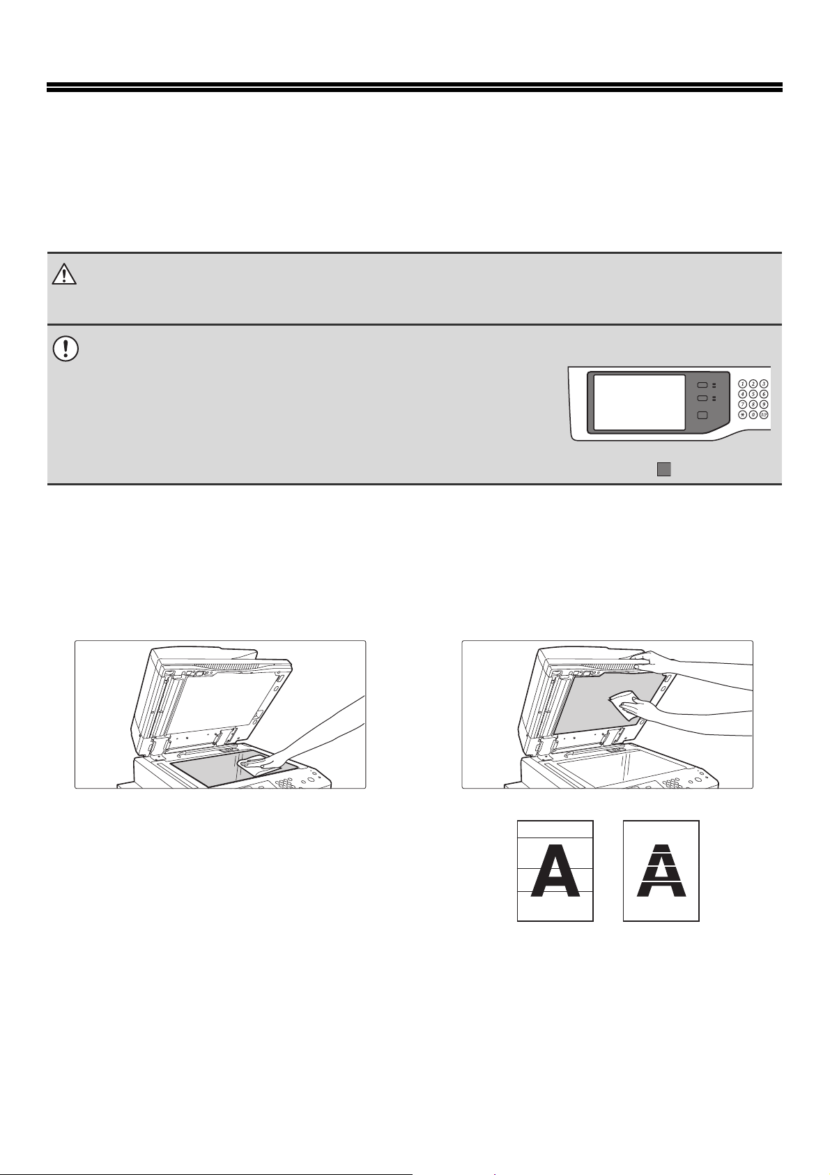
CLEANING THE DOCUMENT GLASS AND AUTOMATIC DOCUMENT FEEDER
If the document glass or document backplate sheet becomes dirty, the dirt will appear in the scanned image. Always
keep these parts clean.
Wipe the parts with a clean, soft cloth.
If necessary, moisten the cloth with water or a small amount of neutral detergent. After wiping with the moistened cloth,
wipe the parts dry with a clean dry cloth.
Document glass Document backplate sheet
Scanning area
If black or white lines appear in images scanned using the
automatic document feeder, clean the scanning area (the thin
long glass next to the document glass).
To clean this area, use the glass cleaner that is stored in the
automatic document feeder. After using the glass cleaner, be
sure to return it to its storage position.
Examples of lines in the image
Black lines White lines
37
Page 40

MAINTENANCE
1
2
3
Open the automatic document feeder and
remove the glass cleaner.
Clean the document scanning area on the
document glass with the glass cleaner.
One scanning area is on the document glass and the other is
inside the automatic document feeder.
Clean the document scanning area in the
automatic document feeder with the glass
cleaner.
(1) Open the scanning area cover on the
automatic document feeder.
Push in the release switch to release the cover.
4
(2) Clean the scanning area in the automatic
document feeder.
(3) Close the cover.
Replace the glass cleaner.
38
Page 41
MAINTENANCE
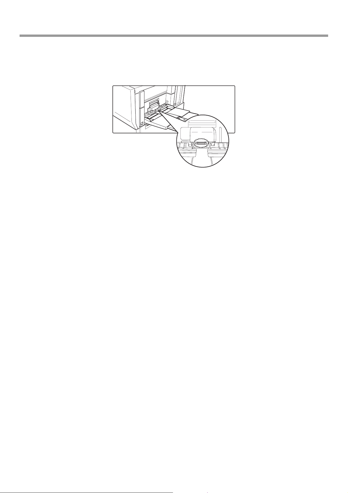
CLEANING THE BYPASS FEED ROLLER
If paper misfeeds frequently occur when feeding or heavy paper through the bypass tray, wipe the surface of the feed
roller with a clean soft cloth moistened with water or a neutral detergent.
39
Page 42

MAINTENANCE
REPLACING THE TONER CARTRIDGES
Be sure to replace the toner cartridge when the message "Change the toner cartridge." appears.
In copy mode
Ready to scan for copy.
(Toner supply is low.)
Ready to scan for copy.
(Change the toner cartridge.)
If you continue to use the machine without replacing
the cartridge, the following message will appear
when the toner runs out.
When the message appears in the message display,
replace the toner cartridge.
Change the toner cartridge.
OK
40
Page 43

MAINTENANCE
1
2
Open the front cover.
Remove the toner cartridge gently.
Hold the toner cartridge with both hands as shown in the
illustration, and pull it out of the machine.
3
Remove the new toner cartridge from the
box and shake it five or six times
horizontally.
5 - 6
Shake the toner cartridge horizontally.
Do not rotate it as shown at left.
It is important to thoroughly shake the supply cartridge for 10 seconds as shown in the diagram in order to ensure
proper operation of toner supply system.
41
Page 44
MAINTENANCE
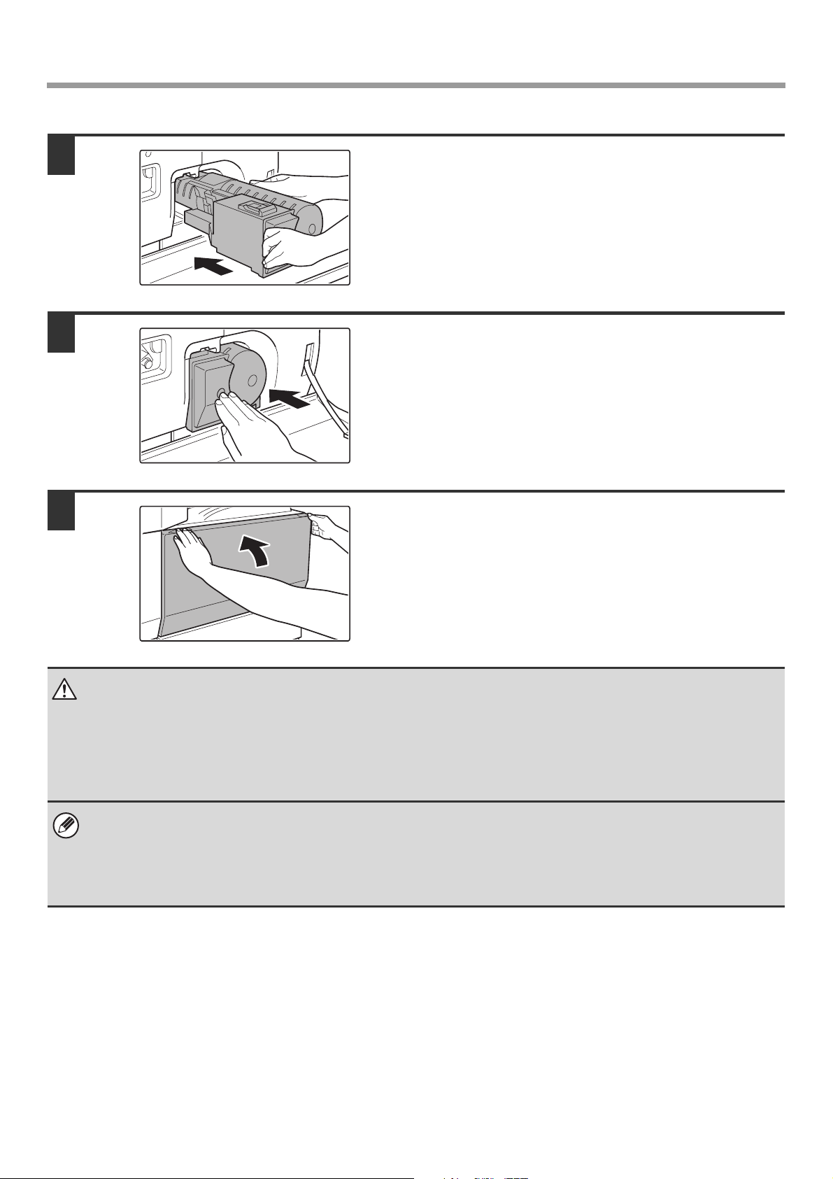
4
5
6
Insert the new toner cartridge.
Align the toner cartridge with the insert hole and push it in as
shown.
Do not rotate the cartridge.
Push the cartridge in until it locks securely
in place.
Close the front cover.
Caution
• Do not throw a toner cartridge into a fire. Toner may fly and cause burns.
• Store toner cartridges out of the reach of small children.
• If a toner cartridge is stored on end, the toner may harden and become unusable. Always store toner cartridges on their
side with the top side up.
• If a toner cartridge other than a SHARP-recommended toner cartridge is used, the machine may not attain full quality and
performance and there is a risk of damage to the machine. Be sure to use a SHARP-recommended toner cartridge.
• Keep the used toner cartridge in a plastic bag (do not discard it). Your service technician will collect the used toner
cartridge.
• To view the approximate amount of toner remaining, continually touch the [COPY] key during printing or when the machine
is idle. The percentage of toner remaining will appear in the display while the key is touched. When the percentage falls to
"25-0%", obtain a new toner cartridge and keep it ready for replacement.
• Depending on your conditions of use, the colour may become faint or the image blurred.
42
Page 45
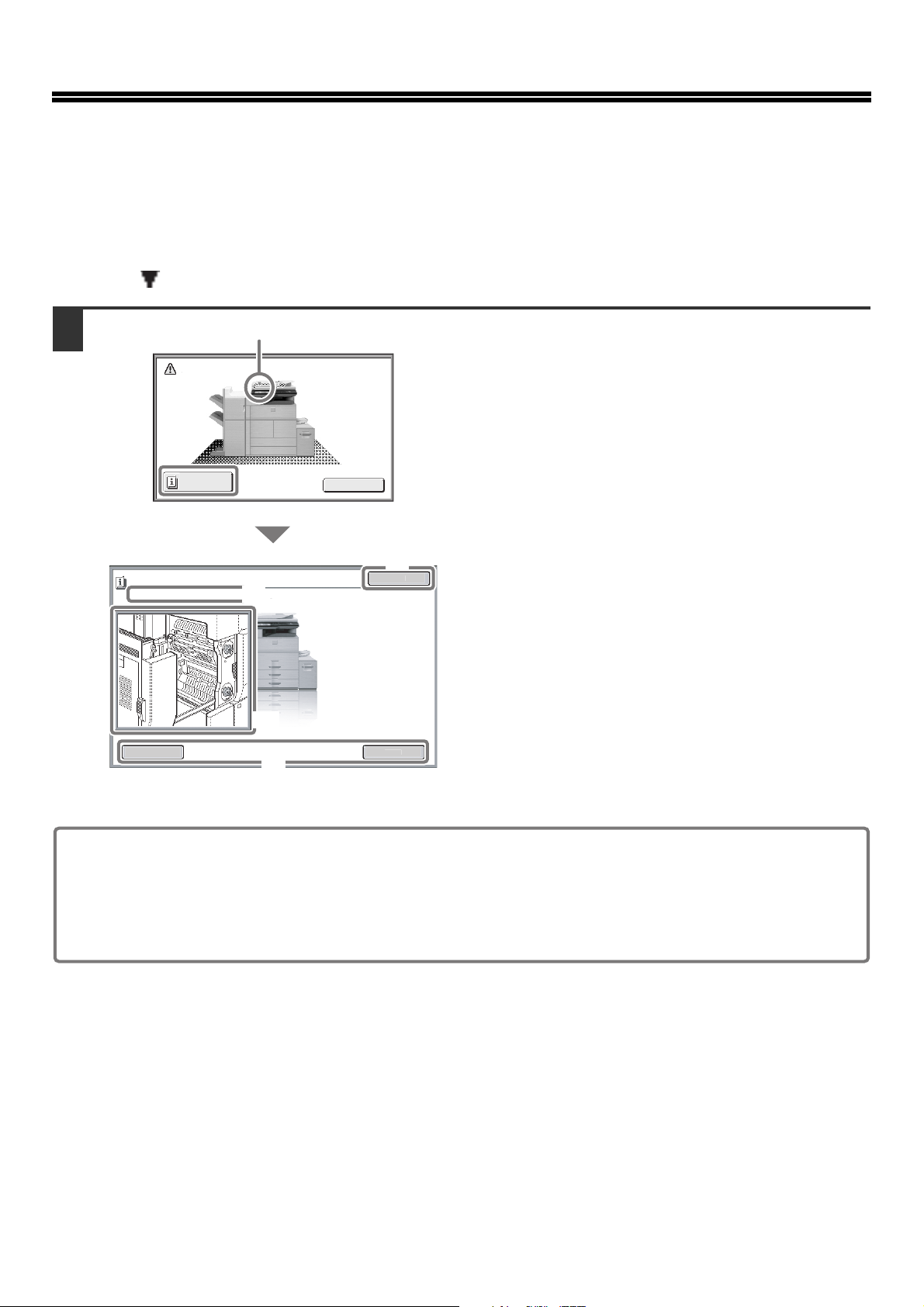
REMOVING MISFEEDS
A mi
n
OK
Exit
O
.
Misfeed Remova
Back
t
When a paper misfeed occurs, the message "A misfeed has occurred." will appear in the touch panel and printing and
scanning will stop. In this event, touch the [Information] key in the touch panel. When the key is touched, instructions for
removing the misfeed will appear. Follow the instructions. When the misfeed is cleared, the message will automatically
clear.
The blinking mark in the image at left indicates the approximate position of the misfeed.
1
Misfeed location
sfeed has occurred.
Informatio
pen the left side cover
l
(A)
(B)
(C)
(D)
Nex
Touch the [Information] key to display the following screen.
(A) Instructions for removing the misfeed
appear here.
(B) Animation showing what to do.
(C) Display the previous screen or the next
screen.
(D) This closes the information screen.
The information screen cannot be closed until the misfeed
is removed.
• While the message appears, printing and scanning cannot be resumed.
• If the message does not clear even after the misfeed has been removed, the causes below are possible. Check
once again.
- The misfeed was not correctly removed.
- A torn piece of paper remains in the machine.
- A cover or unit that was opened or moved to remove the misfeed was not returned to its original position.
For detailed procedures for removing misfeeds, see "REMOVING MISFEEDS" in "8. TROUBLESHOOTING" in the
Operation Guide.
43
Page 46

SUPPLIES
Standard supplies for this product that can replaced by the user include paper, toner cartridges, and staple cartridges for
the finisher.
Be sure to use only SHARP-specified products for the toner cartridges, finisher staple cartridge, saddle stitch finisher
staple cartridge, and transparency film.
For best copying results, be sure to use only Sharp Genuine Supplies which are designed,
engineered, and tested to maximize the life and performance of Sharp products. Look for the
Genuine Supplies label on the toner package.
GENUINE SUPPLIES
Storage of supplies
Proper storage
1. Store the supplies in a location that is:
• clean and dry,
• at a stable temperature,
• not exposed to direct sunlight.
2. Store paper in the wrapper and lying flat.
3. Paper stored in packages standing up or out of the wrapper may curl or become damp, resulting in paper misfeeds.
Storing toner cartridges
Store a new toner cartridge box horizontally with the top side up. Do not store a toner cartridge standing on end. If stored
standing on end, the toner may not distribute well even after shaking the cartridge vigorously, and will remain inside the
cartridge without flowing out.
Staple cartridge
The finisher and saddle stitch finisher require the following staple cartridge:
SF-SC11 (for finisher)
Approx. 5000 per cartridge x 3 cartridges
MX-SC10 (for finisher (3 trays))
Approx. 5000 per cartridge x 3 cartridges
AR-SC3 (for saddle stitch finisher only)
Approx. 2000 per cartridge x 3 cartridges
Supply of spare parts and consumables
The supply of spare parts for repair of the machine is guaranteed for at least 7 years following the termination of
production. Spare parts are those parts of the machine which may break down within the scope of the ordinary use of
the product, whereas those parts which normally exceed the life of the product are not to be considered as spare parts.
Consumables too, are available for 7 years following the termination of production.
44
Page 47
SPECIFICATIONS
Machine specifications / copier specifications
Name
Type
Photoconductive type
Printing method
Developer system
Fusing system
Scanning resolution
Printing resolution
Scanning gradation
Printing gradation
Original sizes / types
Copy sizes
Print margins
Warm-up time
First-copy time
Copy ratios
Continuous copy
Automatic document feeder
Tray 1
Tray 2
Tray 3
Digital Multifunctional System MX-M623U/MX-M753U
Console
OPC drum
Electrophotographic system (laser)
Dry-type two-component magnetic brush development
Heat rollers
Document glass 600 x 300 dpi (factory default values), 600 x 400 dpi, 600 x 600 dpi
Automatic document feeder 600 x 300 dpi (factory default values), 600 x 400 dpi, 600 x 600 dpi
600 x 600 dpi
10 bits
Equivalent to 256 levels
Max. A3 (11" x 17") / sheets, bound documents
Maximum: A3 (11" x 17") Minimum: A5R (5-1/4" x 5-3/4")
Leading edge / trailing edge: total 8 mm (21/64") or less,
near edge / far edge: total 8 mm (21/64") or less
30 seconds or less
(This may vary depending on the ambient conditions.)
MX-M623U: 4.0 seconds or less
MX-M753U: 3.5 seconds or less
(This may vary depending on the state of the machine.)
Variable: 25% to 400% in increments of 1%, total 376 increments (25% to 200% when the automatic
document feeder is used)
Fixed presets: 25%, 50%, 64%, 77%, 100%, 121%, 129%, 200% and 400% for inch sizes;
25%, 50%, 70%, 81%, 86%, 100%, 115%, 122%, 141%, 200% and 400% for AB sizes.
Two reduction ratios and two enlargement ratios can be stored.
999 copies
See "Automatic document feeder specifications".
Paper sizes: A4, 8-1/2" x 11"
Paper weight: Plain paper (60 g/m
Paper capacity: Plain paper (80 g/m
Paper types: SHARP-recommended plain paper, recycled paper, and coloured paper
Paper sizes: A4, B5, 8-1/2" x 11"
Paper weight: Plain paper (60 g/m
Paper capacity: Plain paper (80 g/m
Paper types: SHARP-recommended plain paper, recycled paper, and coloured paper
Paper sizes: A3, B4, A4, A4R, B5, B5R, A5R, 11" x 17", 8-1/2" x 14", 8-1/2" x 13-1/2",
8-1/2" x 13-2/5", 8-1/2" x 13", 8-1/2" x 11", 8-1/2" x 11"R, 7-1/4" x 10-1/2"R,
5-1/2" x 8-1/2"R, 8K, 16K, 16KR (Includes automatic paper size detection function.
Entry of paper sizes up to 297 mm x 432 mm (11-5/8" x 17") is possible.)
Paper weight: Plain paper (60 g/m
209 g/m
Paper capacity: Plain paper (80 g/m
Paper types: SHARP-recommended plain paper, recycled paper, coloured paper, heavy paper*1,
transparency film*
2
(28 lbs. bond to 110 lbs. index))
2
to 105 g/m2 (16 lbs. to 28 lbs.))
2
(21 lbs.)) 800 sheets
2
to 105 g/m2 (16 lbs. to 28 lbs.))
2
(21 lbs.)) 1200 sheets
2
to 105 g/m2 (16 lbs. to 28 lbs.)), heavy paper (106 g/m2 to
2
(21 lbs.)) 500 sheets, heavy paper 80 sheets
1
, labels*1, and tab paper*
1
45
Page 48

SPECIFICATIONS
Machine specifications / copier specifications (Continued)
Paper sizes: A3, B4, A4, A4R, B5, B5R, 11" x 17", 8-1/2" x 14", 8-1/2" x 13-1/2", 8-1/2" x 13-2/5",
8-1/2" x 13", 8-1/2" x 11", 8-1/2" x 11"R, 7-1/4" x 10-1/2"R, 8K, 16K, 16KR (Includes
automatic paper size detection function.)
Tray 4
Bypass tray
Duplex module
Output tray
(Centre tray)
Interface port
Required power supply
Power consumption
Dimensions
Weight
Overall dimensions
*1 The following paper sizes can be used: A4, B5, 8-1/2" x 11", 16K, Custom size (only A4, 8-1/2" x 11" for tab paper)
*2 The following paper sizes can be used: A4, B5, 8-1/2" x 11",16K
*3 Type A connectors are located on the front of the machine and on the right side of the machine at the back (total of two
connectors. Do not use the connectors simultaneously.
To receive power supplied from a type A connector, the total current consumption of the connected device should not exceed
500 mA.
Paper weight: Plain paper (60 g/m
209 g/m
Paper capacity: Plain paper (80 g/m
Paper types: SHARP-recommended plain paper, recycled paper, coloured paper, and heavy paper*
Paper sizes: A3, B4, A4, A4R, B5, B5R, A5R, 11" x 17", 8-1/2" x 14", 8-1/2" x 13-1/2",
8-1/2" x 13-2/5", 8-1/2" x 13", 8-1/2" x 11", 8-1/2" x 11"R, 7-1/4" x 10-1/2"R,
5-1/2" x 8-1/2"R, 8K, 16K, 16KR (Includes automatic paper size detection function.
Entry of paper sizes up to 297 mm x 432 mm (11-5/8" x 17") is possible.)
Paper weight: Thin paper (56 g/m
(16 lbs. to 28 lbs.)), heavy paper (106 g/m
index))
Paper capacity: Standard paper 100 sheets
Paper types: SHARP-recommended plain paper, recycled paper, coloured paper, heavy paper
thin paper, transparency film
Paper sizes: A3, B4, A4, A4R, B5, B5R, A5R, 11" x 17", 8-1/2" x 14", 8-1/2" x 13-1/2",
8-1/2" x 13-2/5", 8-1/2" x 13", 8-1/2" x 11", 8-1/2" x 11"R, 7-1/4" x 10-1/2"R,
5-1/2" x 8-1/2"R, 8K, 16K, 16KR
Paper weight: Plain paper (60 g/m2 to 105 g/m2 (16 lbs. to 28 lbs.)), heavy paper (106 g/m2 to
209 g/m
Paper types: SHARP-recommended plain paper, recycled paper, coloured paper, and heavy paper
Output method: Face-down output
Output capacity: 250 sheets (using SHARP-recommended A4 or 8-1/2" x 11" paper)
(The maximum number of sheets that can be held varies depending on ambient conditions in the
installation location, the type of paper, and the storage conditions of the paper.)
Tray full sensor:Yes
LAN connectivity: 10Base-T / 100Base-TX / 1000Base-T
USB connectivity:
Local voltage ±10% (For the power supply requirements, see the name plate in the lower corner of the
left side of the machine.)
1.8kW
728 mm (W) x 683 mm (D) x 1213 mm (H) (28-42/64" (W) x 26-57/64" (D) x 47-48/64" (H))
Approx. 190 kg (419 lbs.)
1026 mm (W) x 683 mm (D) (40-25/64" (W) x 26-57/64" (D)) (when bypass tray is extended)
2
(28 lbs. bond to 110 lbs. index)
2
(28 lbs. bond to 110 lbs. index))
Type A connector supports USB 2.0*
Compatibility requirements of USB memory
Disk Format: FAT
Type B connector supports USB 2.0 (Hi speed)
2
to 105 g/m2 (16 lbs. to 28 lbs.)), heavy paper (106 g/m2 to
2
(21 lbs.)) 500 sheets, heavy paper 80 sheets
2
to 59 g/m2 (15 lbs. to 16 lbs.)), plain paper (60 g/m2 to 105 g/m2
*1, labels
2
to 209 g/m2 (28 lbs. bond to 110 lbs.
*1, and tab paper
3
1
*
2
*1,
46
Page 49

Continuous copying speeds*
SPECIFICATIONS
Model
Copy ratio
A3, 11" x 17", 8K
MX-M623U MX-M753U
100% / Reduce / Enlarged
34 copies/min. 39 copies/min.
B4, 8-1/2" x 14",
8-1/2" x 13-1/2",
8-1/2" x 13-2/5",
8-1/2" x 13"
A4, B5, 8-1/2" x 11", 16K
39 copies/min. 45 copies/min.
62 copies/min. 75 copies/min.
A4R, B5R, A5R, 8-1/2" x 11"R,
7-1/4" x 10-1/2"R,
45 copies/min. 48 copies/min.
5-1/2" x 8-1/2"R, 16KR
* Copy speed during output of the second copy and following copies when performing continuous one-sided copying of the same
page (excluding offset output) using plain one-sided paper from a tray other than the bypass tray.
Ambient environment
(Humidity)
85%
60%
20%
10°C
(54°F)
30°C
(86°F)
35°C
(91°F)
(Temperature)
Chemical emission (measured according to RAL UZ-122: Edition Jun. 2006)
Ozone
Dust
Styrene
Benzene
TVOC
1.5 mg/h or less
4.0 mg/h or less
1.0 mg/h or less
less than 0.05 mg/h
10 mg/h or less
47
Page 50

SPECIFICATIONS
Acoustic noise emission (measurement according to ISO7779)
MX-M623U MX-M753U
Sound power level LwA
Printing mode (continuous printing)
Standby mode
Sound pressure level LpA (actual measurement)
Bystander positions
7.15 B 7.21 B
5.2 B 5.2 B
56 dB (A) 57 dB (A)
Printing mode
Operator positions
Bystander positions
55 dB (A) 56 dB (A)
41 dB (A) 41 dB (A)
Standby mode
Operator positions
35 dB (A) 35 dB (A)
Automatic document feeder specifications
Original sizes
Original weight
Capacity
*1 Scanning in mono 2 mode of one side only is possible in fax and scan send modes. However, when the resolution is 600 x 600 dpi
in Internet fax mode, the maximum length is 800 mm (31-31/64"). When the resolution is 400 x 400 dpi or 600 x 600 dpi in scan
mode, a long original cannot be scanned.
*2 Paper weights from 35 g/m
A3 to A5, 11" x 17" to 5-1/2" x 8-1/2", long paper
(max. width 297 mm (11-5/8") x max. length 1000 mm*
One-sided 35g/m2 to 128g/m2 (9 lbs. to 34 lbs.)*
Two-sided 50g/m2 to 128g/m2 (13 lbs. to 34 lbs.)
150 sheets (80 g/m2 (21 lbs.)) Maximum stack height of 19.5 mm (49/64")
2
(9 lbs.) to 49 g/m2 (13 lbs.) require the use of slow scan mode.
2
1
(39-23/64"))
48
Page 51

INFORMATION ON DISPOSAL
A. Information on Disposal for Users (private households)
1. In the European Union
Attention: If you want to dispose of this equipment, please do not use the
ordinary dust bin!
Used electrical and electronic equipment must be treated separately and in
accordance with legislation that requires proper treatment, recovery and
recycling of used electrical and electronic equipment.
Following the implementation by member states, private households within the
EU states may return their used electrical and electronic equipment to
designated collection facilities free of charge*. In some countries* your local
retailer may also take back your old product free of charge if you purchase a
similar new one.
*) Please contact your local authority for further details.
If your used electrical or electronic equipment has batteries or accumulators,
please dispose of these separately beforehand according to local
requirements.
By disposing of this product correctly you will help ensure that the waste
undergoes the necessary treatment, recovery and recycling and thus prevent
potential negative effects on the environment and human health which could
otherwise arise due to inappropriate waste handling.
Attention: Your product is
marked with this symbol. It
means that used electrical
and electronic products
should not be mixed with
general household waste.
There is a separate
collection system for these
products.
2. In other Countries outside the EU
If you wish to discard this product, please contact your local authorities and ask for the correct method of disposal.
For Switzerland: Used electrical or electronic equipment can be returned free of charge to the dealer, even if you don't
purchase a new product. Further collection facilities are listed on the homepage of www.swico.ch or www.sens.ch.
B. Information on Disposal for Business Users.
1. In the European Union
If the product is used for business purposes and you want to discard it:
Please contact your SHARP dealer who will inform you about the take-back of the product. You might be charged for the
costs arising from take-back and recycling. Small products (and small amounts) might be taken back by your local
collection facilities.
For Spain: Please contact the established collection system or your local authority for take-back of your used products.
2. In other Countries outside the EU
If you wish to discard of this product, please contact your local authorities and ask for the correct method of disposal.
49
Page 52

50
Page 53

✂
Information that the administrator of the machine requires is printed on
the back of this page.
(Separate this page from the manual and keep it in a safe place. In
addition, fill in the name of the administrator and the administrator's
contact information in the left hand margin.)
Administrator Name: Contact at:
51
Page 54

TO THE ADMINISTRATOR OF THE
MACHINE
(Separate this page from the manual and keep it in a safe place.)
Factory default passwords
When accessing the system settings, the administrator password is required to log in with administrator
rights. The system settings can be configured in the Web pages as well as on the operation panel. To
access the system settings using the Web pages, a password is also required.
Factory default administrator password
Factory default setting: admin
Store a new administrator password as soon as the machine is installed.
Once the administrator password has been changed, the new password is required to restore the factory
default password. Take care to remember the new password.
Factory default passwords (Web pages)
There are two factory default accounts: "Administrator" and "User". A person who logs in as an
"Administrator" can configure all settings in the Web pages. In addition, an administrator can restrict access
to other settings by enabling "User" accounts.
The factory default passwords are shown below.
Factory default account Factory default password
User users users
Administrator admin admin
Forwarding all transmitted and received data to the administrator
(document administration function)
This function is used to forward all data transmitted and received by the machine to a specified destination
(Scan to E-mail address, Scan to FTP destination, Scan to Network Folder destination, or Scan to Desktop
destination).
This function can be used by the administrator of the machine to archive all transmitted and received data.
To configure the document administration settings, click [Application Settings] and then [Document
Administration Function] in the Web page menu. (Administrator rights are required.)
• The format, exposure, and resolution settings of transmitted and received data remain in effect when the data
is forwarded.
• When forwarding is enabled for data sent in fax mode,
• The [Direct TX] key does not appear in the touch panel.
• Quick online transmission and dialling using the speaker cannot be used.
✂
52
Page 55

TO THE ADMINISTRATOR OF THE MACHINE
For the users of the fax function
Important safety instructions
• If any of your telephone equipment is not operating properly, you should immediately remove it from your telephone line, as it may
cause harm to the telephone network.
• The AC power outlet shall be installed near the equipment and shall be easily accessible.
• Never install telephone wiring during a lightning storm.
• Never install telephone jacks in wet locations unless the socket is specifically designed for wet locations.
• Never touch uninsulated telephone wires or terminals unless the telephone line has been disconnected at the network interface.
• Use caution when installing or modifying telephone lines.
• Avoid using a telephone (other than a cordless type) during an electrical storm. There may be a remote risk of electric shock from
lightning.
• Do not use a telephone to report a gas leak in the vicinity of the leak.
• Do not install or use the machine near water, or when you are wet. Take care not to spill any liquids on the machine.
• Save these instructions.
53
Page 56

TO THE ADMINISTRATOR OF THE MACHINE
Trademark acknowledgments
The following trademarks and registered trademarks are used in conjunction with the machine and its peripheral devices and
accessories.
Microsoft®, Windows®, Windows® 98, Windows® Me, Windows NT® 4.0, Windows® 2000, Windows® XP, Windows Server®
•
2003, Windows Vista
Microsoft Corporation in the U.S.A. and other countries.
• PostScript is a registered trademark of Adobe Systems Incorporated.
• Adobe and Flash are registered trademarks or trademarks of Adobe Systems Incorporated in the United States and other
countries.
• Adobe, the Adobe logo, Acrobat, the Adobe PDF logo, and Reader are registered trademarks or trademarks of Adobe Systems
Incorporated in the United States and other countries.
•
Macintosh, Mac OS, AppleTalk, EtherTalk and LaserWriter are trademarks of Apple Inc., registered in the U.S. and other countries.
• Netscape Navigator is a trademark of Netscape Communications Corporation.
• Mozilla® and Firefox® are registered trademarks or trademarks of the Mozilla Foundation in the U.S.A. and other countries.
• PCL is a registered trademark of the Hewlett-Packard Company.
• IBM, PC/AT, and PowerPC are trademarks of International Business Machines Corporation.
• Sharpdesk is a trademark of Sharp Corporation.
• Sharp OSA is a trademark of Sharp Corporation.
• RealVNC is a trademark of RealVNC Limited.
• All other trademarks and copyrights are the property of their respective owners.
®
, Windows Server® 2008, Windows® 7 and Internet Explorer® are registered trademarks or trademarks of
Candid and Taffy are trademarks of Monotype Imaging, Inc. registered in the United States Patent and Trademark Office and may
be registered in certain jurisdictions. CG Omega, CG Times, Garamond Antiqua, Garamond Halbfett, Garamond Kursiv,
Garamond and Halbfett Kursiv are trademarks of Monotype Imaging, Inc. and may be registered in certain jurisdictions. Albertus,
Arial, Coronet, Gill Sans, Joanna and Times New Roman are trademarks of The Monotype Corporation registered in the United
States Patent and Trademark Office and may be registered in certain jurisdictions. Avant Garde, ITC Bookman, Lubalin Graph,
Mona Lisa, Zapf Chancery and Zapf Dingbats are trademarks of International Typeface Corporation registered in the United
States Patent and Trademark Office and may be registered in certain jurisdictions. Clarendon, Eurostile, Helvetica, Optima,
Palatino, Stempel Garamond, Times and Univers are trademarks of Heidelberger Druckmaschinen AG, which may be registered
in certain jurisdictions, exclusively licensed through Linotype Library GmbH, a wholly owned subsidiary of Heidelberger
Druckmaschinen AG. Apple Chancery, Chicago, Geneva, Monaco and New York are trademarks of Apple Computer Inc. and may
be registered in certain jurisdictions. HGGothicB, HGMinchoL, HGPGothicB and HGPMinchoL are trademarks of Ricoh
Company, Ltd. and may be registered in some jurisdictions. Wingdings is a registered trademark of Microsoft Corporation in the
United States and other countries. Marigold and Oxford are trademarks of Arthur Baker and may be registered in some
jurisdictions. Antique Olive is a trademark of Marcel Olive and may be registered in certain jurisdictions. Hoefler Text is a
trademark of Johnathan Hoefler and may be registered in some jurisdictions. ITC is a trademark of International Typeface
Corporation registered in the United States Patent and Trademark Office and may be registered in certain jurisdictions. Agfa is a
trademark of the Agfa-Gevaert Group and may be registered in certain jurisdictions. Intellifont, MicroType and UFST are
trademarks of Monotype Imaging, Inc. registered in the United States Patent and Trademark Office and may be registered in
certain jurisdictions. Macintosh and TrueType are trademarks of Apple Computer Inc. registered in the United States Patent and
Trademark Office and other countries. PostScript is a trademark of Adobe Systems Incorporated and may be registered in some
jurisdictions. HP, PCL, FontSmart and LaserJet are trademarks of Hewlett-Packard Company and may be registered in some
jurisdictions. The Type 1 processor resident in Monotype Imaging's UFST product is under licence from Electronics For Imaging,
Inc. All other trademarks are the property of their respective owners.
54
Page 57

Page 58

Page 59

SHARP ELECTRONICS (Europe) GmbH
Sonninstraße 3, D-20097 Hamburg
Page 60

MX-M623U/MX-M753U START GUIDE
PRINTED IN FRANCE
TINSE4654GHZZ
 Loading...