

Page 1
TopPage
LC-80LE632U
SERVICE MANUAL
No. S91T680LE632U
LCD COLOR TELEVISION
MODEL
In the interests of user-safety (Required by safety regulations in some countries) the set should be restored to its original condition and only parts identical to those specified should be used.
LC-80LE632U
OUTLINE
In this Service Manual, the modifications from Model LC-70LE732U (No. S31O870LE732U) are focused on. For what
is left out herein, please refer back to the Service Manual of the previous model LC-70LE732U (No. S31O870LE732U).
CONTENTS
OUTLINE AND DIFFERENCES FROM BASE MODEL
OUTLINE.............................................................i
DIFFERENCES FROM BASE MODEL...............i
MAJOR SERVICE PARTS .................................ii
SAFETY PRECAUTION
IMPORTANT SERVICE SAFETY PRE-
CAUTION .......................................................... iii
PRECAUTIONS A PRENDRE LORS DE
LA REPARATION.............................................. iv
PRECAUTIONS FOR USING LEAD-FREE
SOLDER ............................................................v
CHAPTER 1. SPECIFICATIONS
[1] SPECIFICATIONS ......................................... 1-1
CHAPTER 2. OPERATION MANUAL
[1] OPERATION MANUAL .................................. 2-1
CHAPTER 3. DIMENSIONS
[1] DIMENSIONS................................................3-1
CHAPTER 4. REMOVING OF MAJOR PARTS
[1] REMOVING OF MAJOR PARTS...................4-1
[2] The location putting on the heat measure
sheet..............................................................4-9
[3] Precautions for assembly ............................4-10
CHAPTER 5. ADJUSTMENT
[1] ADJUSTMENT PROCEDURE ......................5-1
CHAPTER 6. OVERALL WIRING DIAGRAM
[1] OVERALL WIRING DIAGRAM......................6-1
Parts Guide
Parts marked with " " are important for maintaining the safety of the set. Be sure to replace these parts with specified ones for maintaining the
safety and performance of the set.
This document has been published to be used for
after sales service only.
The contents are subject to change without notice.
Page 2
LC-80LE632U
LC80LE632U
OUTLINE AND DIFFERENCES FROM BASE MODEL
Service Manual
OUTLINE
In this Service Manual, the modifications from Model LC-70LE732U (No. S31O870E732U) are focused on. For what is left out herein, please refer
back to the Service Manual of the previous model LC-70LE732U (No. S31O870E732U).
DIFFERENCES FROM BASE MODEL
Ref. No. Description LC-70LE732U
(S31O870LE732U)
PRINTED WIRING BOARD ASSEMBLIES
N MAIN Unit DKEYMF733FM19 DKEYMF733FM49 D Chanded
N R/C OPC Unit DUNTKF494FM01 ← - No Changed
N ICON Unit DUNTKF770FM02 ← - No Changed
N KEY Unit DUNTKF800FM51 DUNTKF800FM50 D Changed
N WiFi Unit RUNTKA810WJQZ ← - No Changed
N POWER/DRIVE Unit RUNTKA857WJQZ RUNTKA903WJQZ D Chanded
N LCD Control Unit DUNTKF778FM04 DUNTKF778FM12 D Chanded
LCD Panel Module
N LCD Panel Module Unit R1LK695D3GW30Z R1LK800D3GW10Z D Chanded
CABINET AND MECHANICAL PARTS
Please refer to a Parts Guide.
SUPPLIED ACCESSORIES/PACKING PARTS (NOT REPLACEMENT ITEM)
Please refer to a Parts Guide.
SERVICE JIG (USE FOR SERVICING)
Please refer to a Parts Guide.
LC-80LE632U
(S91T680LE632U)
Inter-
change-
ability
Interchangeability
Completely interchangeableA:
Interchangeable from
B:
OLD to NEW
=
ψ
NEWOLD
NEWOLD
Interchangeable from
C:
NEWtoOLD
Not interchangeableD:
NEW OLD
ψ
X
Note
OLDNEW
i
Page 3
LC-80LE632U
MAJOR SERVICE PARTS
PWB Unit
Ref. No. Parts No. Description
N DKEYMF733FM49 MAIN Unit
N DUNTKF494FM01 R/C OPC Unit
N DUNTKF770FM02 ICON Unit
N DUNTKF800FM50 KEY Unit
N RUNTKA810WJQZ WiFi Unit
N RUNTKA903WJQZ POWER/DRIVE Unit
N DUNTKF778FM12 LCD Control Unit
NOTE: (*1) Replace MAIN Unit (DKEYDF733FM**) in case of IC8401, IC3303 or IC8455 failure.
OTHER Unit
Ref. No. Parts No. Description
N R1LK800D3GW10Z 80" LCD Panel Module Unit(LK800D3GW10Z)
IC For Exclusive Use Of The Service
Ref. No. Parts No. Description Q'ty
IC2001 RH-iXD241WJNBQ IC R5F21368CNFP (Monitor Microcomputer) 1
Service Jigs
Ref. No. Parts No. Description Q'ty
N QCNW-C222WJQZ Connecting Cord L=1000mm 80pins, LCD Control Unit to LCD Panel Unit 2
N QCNW-F676WJQZ Connecting Cord L=1000mm 41pins, Main to LCD Control Unit (LW) 1
N QCNW-L795WJQZ Connecting Cord L=1000mm 24pins, Main to POWER Unit (PD) 1
N QCNW-G405WJQZ Connecting Cord L=1000mm 4pins, Power to LCD Control Unit (PL) 1
ii
Page 4
LC-80LE632U
LC80LE632U
SAFETY PRECAUTION
Service Manual
IMPORTANT SERVICE SAFETY PRECAUTION
Service work should be performed only by qualified service technicians who are thoroughly familiar with all safety checks and the
servicing guidelines which follow:
WARNING
1. For continued safety, no modification of any circuit should be
attempted.
2. Disconnect AC power before servicing.
CAUTION: FO R C ON TI NU ED PROTECTION
AGAINST A RISK OF FIRE REPLACE ONLY WITH
SAME TYPE FUSE.
F7003 (250V 6.3A)
• Use an AC voltmeter having with 5000 ohm per volt, or higher, sensitivity or measure the AC voltage drop across the resistor.
• Connect the resistor connection to all exposed metal parts having a
return to the chassis (antenna, metal cabinet, screw heads, knobs
and control shafts, escutcheon, etc.) and measure the AC voltage
drop across the resistor.
All checks must be repeated with the AC cord plug connection
reversed. (If necessary, a nonpolarized adaptor plug must be used
only for the purpose of completing these checks.)
Any reading of 0.75 Vrms (this corresponds to 0.5 mA rms AC.) or
more is excessive and indicates a potential shock hazard which
must be corrected before returning the monitor to the owner.
DVM
AC SCALE
BEFORE RETURNING THE RECEIVER (Fire &
Shock Hazard)
Before returning the receiver to the user, perform the following
safety checks:
3. Inspect all lead dress to make certain that leads are not pinched,
and check that hardware is not lodged between the chassis and
other metal parts in the receiver.
4. Inspect all protective devices such as non-metallic control knobs,
insulation materials, cabinet backs, adjustment and compartment
covers or shields, isolation resistor-capacitor networks, mechanical
insulators, etc.
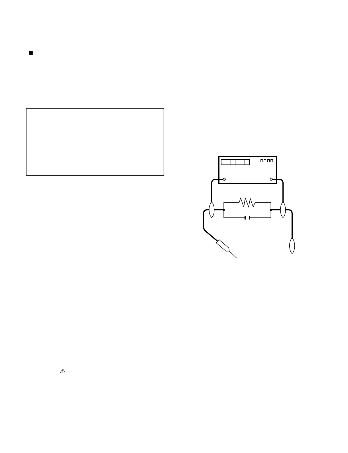
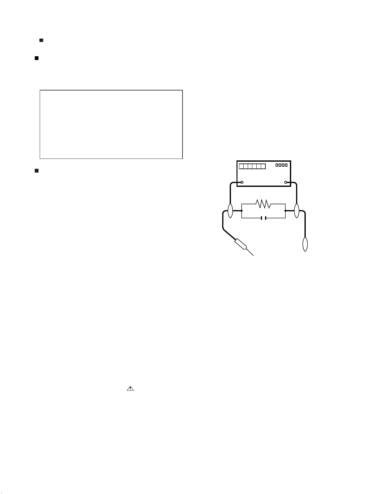
5. To be sure that no shock hazard exists, check for leakage current
in the following manner.
• Plug the AC cord directly into a 120 volt AC outlet.
• Using two clip leads, connect a 1.5k ohm, 10 watt resistor paralleled by a 0.15µF capacitor in series with all exposed metal cabinet
parts and a known earth ground, such as electrical conduit or electrical ground connected to an earth ground.
///////////////////////////////////////////////////////////////////////////////////////////////////////////////////////////////////////////////////////////////////////////////////////////////////////////////////////////////////////////
TO EXPOSED
METAL PARTS
1.5k ohm
10W
0.15µF
TEST PROBE
CONNECT TO
KNOWN EARTH
GROUND
SAFETY NOTICE
Many electrical and mechanical parts in LCD color television have
special safety-related characteristics.
These characteristics are often not evident from visual inspection, nor
can protection afforded by them be necessarily increased by using
replacement components rated for higher voltage, wattage, etc.
Replacement parts which have these special safety characteristics are
identified in this manual; electrical components having such features
are identified by " " and shaded areas in the Replacement Parts List
and Schematic Diagrams.
///////////////////////////////////////////////////////////////////////////////////////////////////////////////////////////////////////////////////////////////////////////////////////////////////////////////////////////////////////////
For continued protection, replacement parts must be identical to those
used in the original circuit.
The use of a substitute replacement parts which do not have the same
safety characteristics as the factory recommended replacement parts
shown in this service manual, may create shock, fire or other hazards.
iii
Page 5
PRECAUTIONS A PRENDRE LORS DE LA REPARATION
Ne peut effectuer la réparation qu' un technicien spécialisé qui s'est parfaitement accoutumé à toute vérification de sécurité et aux
conseils suivants.
AVERTISSEMENT
1.
N'entreprendre aucune modification de tout circuit. C'est dangereux.
2.
Débrancher le récepteur avant toute réparation.
CAUTION: FO R C ON TI N U E D PROTECTION
AGAINST A RISK OF FIRE REPLACE ONLY WITH
SAME TYPE FUSE.
F7003 (250V 6.3A)
•
Utiliser un voltmètre CA d'une sensibilité d'au moins 5000Ω/V pour
mesurer la chute de tension en travers de la résistance.
•
Toucher avec la sonde d'essai les pièces métalliques exposées qui
présentent une voie de retour au châssis (antenne, coffret métallique, tête des vis, arbres de commande et des boutons, écusson,
etc.) et mesurer la chute de tension CA en-travers de la résistance.
Toutes les vérifications doivent être refaites après avoir inversé la
fiche du cordon d'alimentation. (Si nécessaire, une prise
d'adpatation non polarisée peut être utilisée dans le but de terminer ces vérifications.)
La tension de pointe mesurèe ne doit pas dépasser 0.75V (correspondante au courant CA de pointe de 0.5mA).
Dans le cas contraire, il y a une possibilité de choc électrique qui
doit être supprimée avant de rendre le récepteur au client.
LC-80LE632U
VERIFICATIONS CONTRE L'INCEN-DIE ET LE
CHOC ELECTRIQUE
Avant de rendre le récepteur à l'utilisateur, effectuer les vérifications suivantes.
3.
Inspecter tous les faisceaux de câbles pour s'assurer que les fils
ne soient pas pincés ou qu'un outil ne soit pas placé entre le châssis et les autres pièces métalliques du récepteur.
4.
Inspecter tous les dispositifs de protection comme les boutons de
commande non-métalliques, les isolants, le dos du coffret, les couvercles ou blindages de réglage et de compartiment, les réseaux
de résistancecapacité, les isolateurs mécaniques, etc.
5.
S'assurer qu'il n'y ait pas de danger d'électrocution en vérifiant la
fuite de courant, de la facon suivante:
•
Brancher le cordon d'alimentation directem-ent à une prise de courant de 120V. (Ne pas utiliser de transformateur d'isolation pour
cet essai).
•
A l'aide de deux fils à pinces, brancher une résistance de 1.5 kΩ
10 watts en parallèle avec un condensateur de 0.15µF en série
avec toutes les pièces métalliques exposées du coffret et une terre
connue comme une conduite électrique ou une prise de terre
branchée à la terre.
/////////////////////////////////////////////////////////////////////////////////////////////////////////////////////////////////////////////////////////////////////////////////////////////////////////////////////////////////////////////
AUX PIECES
METALLIQUES
EXPOSEES
DVM
ECHELLE CA
1.5k ohm
10W
0.15
µ
SONDE D'ESSAI
F
BRANCHER A UNE
TERRE CONNUE
AVIS POUR LA SECURITE
De nombreuses pièces, électriques et mécaniques, dans les téléviseur ACL présentent des caractéristiques spéciales relatives à la sécurité, qui ne sont souvent pas évidentes à vue. Le degré de protection ne peut pas être nécessairement augmentée en utilisant des
pièces de remplacement étalonnées pour haute tension, puissance,
etc.
Les pièces de remplacement qui présentent ces caractéristiques sont
identifiées dans ce manuel; les pièces électriques qui présentent ces
particularités sont identifiées par la marque " " et hachurées dans la
liste des pièces de remplacement et les diagrammes schématiques.
/////////////////////////////////////////////////////////////////////////////////////////////////////////////////////////////////////////////////////////////////////////////////////////////////////////////////////////////////////////////
Pour assurer la protection, ces pièces doivent être identiques à celles
utilisées dans le circuit d'origine. L'utilisation de pièces qui n'ont pas
les mêmes caractéristiques que les pièces recommandées par l'usine,
indiquées dans ce manuel, peut provoquer des électrocutions, incendies, radiations X ou autres accidents.
iv
Page 6
LC-80LE632U
PRECAUTIONS FOR USING LEAD-FREE SOLDER
Employing lead-free solder
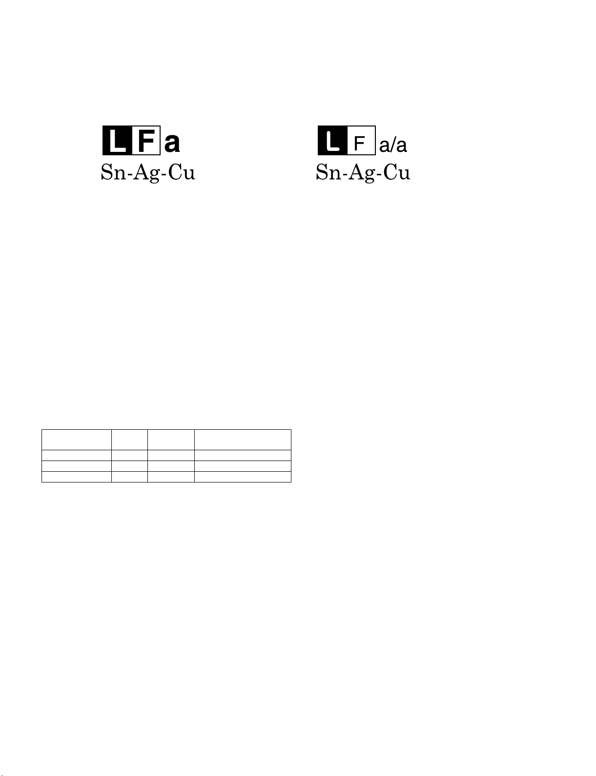
• “PWBs” of this model employs lead-free solder. The LF symbol indicates lead-free solder, and is attached on the PWBs and service manuals. The
alphabetical character following LF shows the type of lead-free solder.
Example:
Indicates lead-free solder of tin, silver and copper. Indicates lead-free solder of tin, silver and copper.
Using lead-free wire solder
• When fixing the PWB soldered with the lead-free solder, apply lead-free wire solder. Repairing with conventional lead wire solder may cause damage or accident due to cracks.
As the melting point of lead-free solder (Sn-Ag-Cu) is higher than the lead wire solder by 40 °C, we recommend you to use a dedicated soldering
bit, if you are not familiar with how to obtain lead-free wire solder or soldering bit, contact our service station or service branch in your area.
Soldering
• As the melting point of lead-free solder (Sn-Ag-Cu) is about 220 °C which is higher than the conventional lead solder by 40 °C, and as it has poor
solder wettability, you may be apt to keep the soldering bit in contact with the PWB for extended period of time. However, Since the land may be
peeled off or the maximum heat-resistance temperature of parts may be exceeded, remove the bit from the PWB as soon as you confirm the
steady soldering condition.
Lead-free solder contains more tin, and the end of the soldering bit may be easily corroded. Make sure to turn on and off the power of the bit as
required.
If a different type of solder stays on the tip of the soldering bit, it is alloyed with lead-free solder. Clean the bit after every use of it.
When the tip of the soldering bit is blackened during use, file it with steel wool or fine sandpaper.
• Be careful when replacing parts with polarity indication on the PWB silk.
Lead-free wire solder for servicing
PARTS CODE
ZHNDAi123250E BL J φ0.3mm 250g (1roll)
ZHNDAi126500E BK J φ0.6mm 500g (1roll)
ZHNDAi12801KE BM J φ1.0mm 1kg (1roll)
PRICE
RANK
PART
DELIVERY
DESCRIPTION
v
Page 7
LC80LE632U
CHAPTER 1. SPECIFICATIONS
[1] SPECIFICATIONS
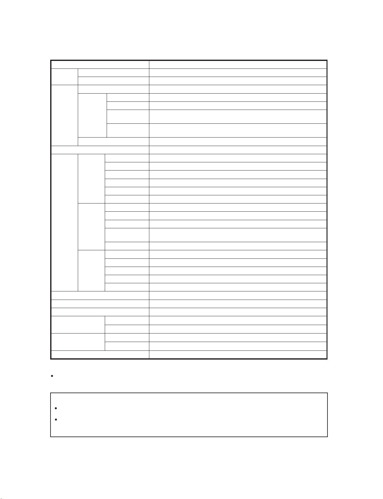
Item Model: LC-80LE632U
LCD
panel
TV
Function
Audio out 10 Wx2
Terminals
OSD language English/French/Spanish
Power Requirement AC 120 V, 60 Hz
Power Consumption 307 W (0.1 W Standby with AC 120 V)
Weight
Dimension
(WxHxD)
Operating temperature
*1
Emergency alert messages via Cable are unreceivable.
*2
The dimensional drawings are shown on the inside back cover.
As part of policy of continuous improvement, SHARP reserves the right to make design and specification changes for
product improvement without prior notice. The performance specification figures indicated are nominal values of production
units. There may be some deviations from these values in individual units.
Size 80" Class (80" Diagonal)
Resolution 2,073,600 pixels (1,920x1,080)
TV-standard (CCIR) American TV Standard ATSC/NTSC System
VHF/UHF VHF 2-13ch, UHF 14-69ch
CATV 1-135ch (non-scrambled channel only)
Receiving
Channel
Digital Terrestrial
Broadcast (8VSB)
Digital cable
*1
(64/256 QAM)
2-69ch
1-135ch (non-scrambled channel only)
Audio multiplex BTSC System
HDMI 1 HDMI in with HDCP, Audio in (Ø 3.5 mm stereo jack)
HDMI 2 HDMI in with HDCP
Back panel
vertical
inputs
HDMI 3 HDMI in with HDCP
HDMI 4 HDMI in with HDCP
AUDIO OUT Audio out (Ø 3.5 mm stereo jack)
USB 1 Photo/Music/Video mode, Software update
COMPONENT COMPONENT in
VIDEO 1 AV in
Back panel
surface
inputs
VIDEO 2 AV in
PC IN
ANALOG RGB (PC) in (15-pin mini D-sub female connector),
Audio in (Ø 3.5 mm stereo jack)
RS-232C 9-pin D-sub male connector
75ǡ Unbalance, F Type x 1 for Analog (VHF/UHF/CATV) and Digital (AIR/CABLE)
Optical Digital audio outputx1 (PCM/Dolby Digital)
Back panel
horizontal
inputs
ANT/CABLE
AUDIO IN Audio in (Ø 3.5 mm stereo jack)
DIGITAL AUDIO OUTPUT
ETHERNET Network connector
USB 2 Photo/Music/Video mode, Software update
TV + stand 131.2 lbs./59.5 kg
TV only 122.4 lbs./55.5 kg
*2
TV + stand 73
TV only 73
+32°F to+104°F (0°C to+40°C)
LC-80LE632U
Service Manual
5
/
5
/
3
/
45
x
16
25
43
x
16
3
/32inch
17
x
32
29
3
/
/32inch
x
32
Cautions regarding use in high and low temperature environments
When the unit is used in a low temperature space (e.g. room, office), the picture may leave trails or appear slightly delayed
This is not a malfunction, and the unit will recover when the temperature returns to normal.
Do not leave the unit in a hot or cold location. Also, do not leave the unit in a location exposed to direct sunlight or near a
heater, as this may cause the cabinet to deform and the front panel to malfunction.
Storage temperature:-4°F to+140°F (-20°C to+60°C)
1 – 1
.
Page 8
LC-80LE632U
LC80LE632U
CHAPTER 2. OPERATION MANUAL
[1] OPERATION MANUAL
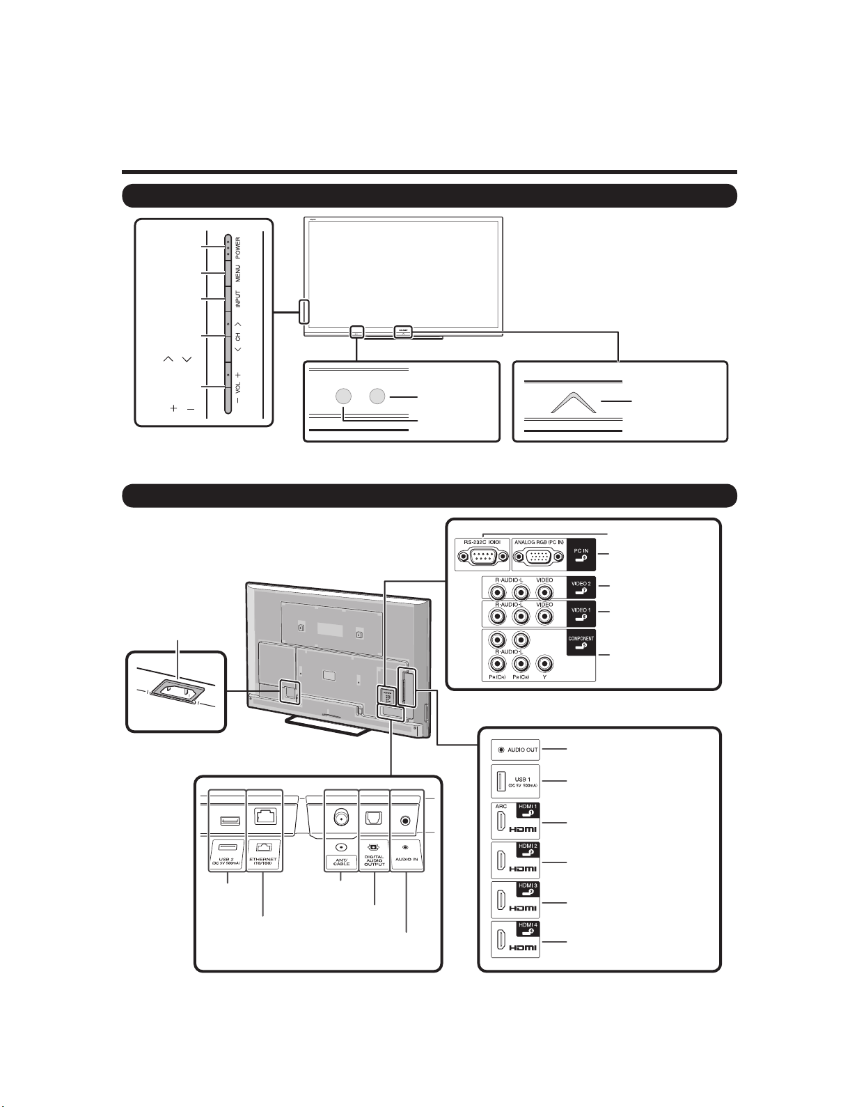
Part Names
TV (Front/Side)
*1
POWER
button
MENU
button
INPUT
button
Channel
buttons
(CH /)
Service Manual
Volume
buttons
(VOL /)
TV (Rear )
AC INPUT terminal
OPC sensor *2
Remote
control sensor
*1 Button operations.
*2 OPC: Optical Picture Control
*1
AUDIO OUT terminal
*2
USB 1 terminal
Center Icon
illumination
*2
RS-232C terminal
PC IN terminal
VIDEO 2
terminals
VIDEO 1
terminals
COMPONENT
terminals
*2
USB 2
terminal
ETHERNET
terminal
*1 Connecting the AC cord.
*2 External equipment connection.
*3 Details on the Audio Select function.
Antenna/
Cable in
DIGITAL AUDIO
OUTPUT terminal
AUDIO IN terminal
(shared for PC IN
and HDMI 1) *3
HDMI 1 terminal
ARC:Audio Return Channel
HDMI 2 terminal
HDMI 3 terminal
HDMI 4 terminal
2 – 1
Page 9
LC-80LE632U
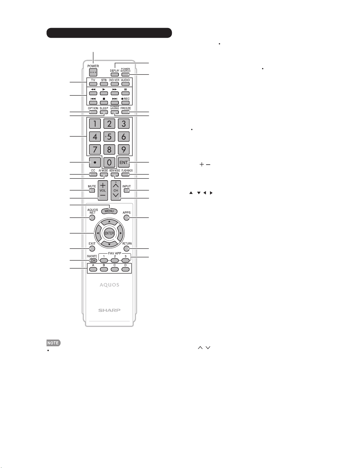
Remote Control Unit
1
2
3
4
5
6
7
8
9
10
11
12
13
14
15
16
17
18
19
20
21
22
23
24
25
26
27
28
29
1POWER: Switch the TV power on or enter standby.
2 TV,STB,DVD VCR,AUDIO: Switches the remote
control for TV, STB, BD, DVD, VCR and AUDIO operation.
* To enter the code registration mode, you need to press
an appropriate button (STB,DVD VCR or AUDIO) and
DISPLAY atthesametime.
3 External equipment operational buttons:Operate the
external equipment.
4 OPTION: Display the Link Operation Menu screen. This
button will function only when AQUOS LINK is used.
5 SLEEP: Set the sleep timer.
60-9: Set the channel.
7(DOT)
8CC: Display captions from a closed-caption source.
AV MODE: Select an audio or video setting.
9
10 MUTE: Mute the sound.
11 VOL / : Set the volume.
12 MENU: Display the menu screen.
13 AQUOS NET: Switches the display to the TV+Web,
Web or TV screen.
14 ///,ENTER: Select a desired item on the screen.
15 EXIT: Turn off the menu screen.
16 FAVORITE CH: Set the favorite channels.
17 A, B, C, D: Select 4 preset favorite channels in 4 different
categories.
While watching, you can toggle the selected channels by
pressingA, B, C and D.
18 DISPLAY: Display the channel information.
19 POWER (SOURCE): Turns the power of the external
equipment on and off.
20 FREEZE: Set the still image. Press again to return to
normal screen.
21 POWER SAVING: Select Power Saving settings.
When using the remote control unit, point it at the TV.
22 ENT: Jumps to a channel after selecting with the0-9
buttons.
23 FLASHBACK: Return to the previous channel or external
input mode.
24 VIEW MODE: Select the screen size.
25 INPUT: Select a TV input source. (TV, HDMI1, HDMI2,
HDMI3, HDMI4, COMPONENT, VIDEO1, VIDEO2, PC IN,
Home Network (DLNA), USB)
26 CH / : Select the channel.
27 APPS: Display the application window.
28 RETURN: Return to the previous menu screen.
29 FAV APP 1, 2, 3: You can assign your favorite
applications to these buttons.
2 – 2
Page 10
LC-80LE632U
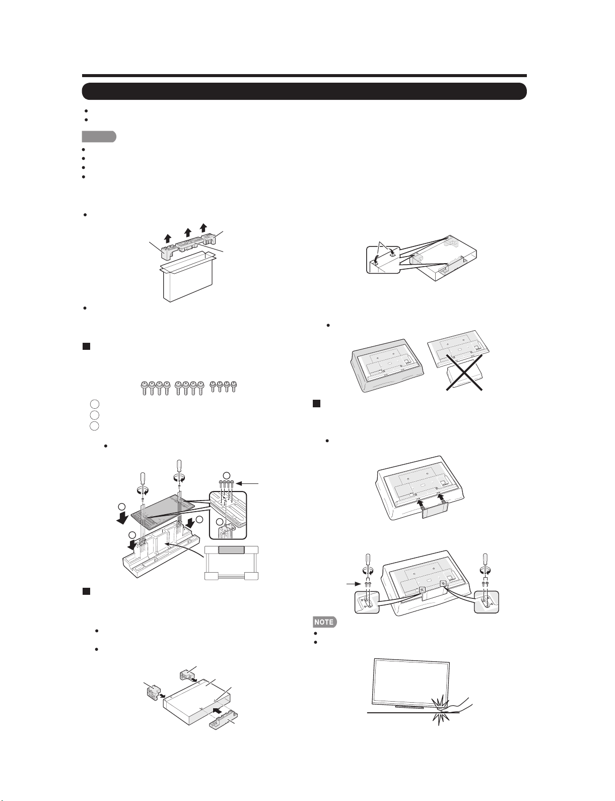
QUICK REFERENCE
Attaching the Stand
Before attaching (or detaching) the stand, unplug the AC cord.
Before performing work spread cushioning over the base area to lay the TV on. This will prevent it from being damaged.
CAUTION
Attach the stand in the correct direction.
Do not remove the stand from the TV unless using a wall mount bracket to mount it.
Be sure to follow the instructions. Incorrect installation of the stand may result in the TV falling over.
After attaching the stand to the TV, do not hold the stand when you put up, set up, move or lay down the TV.
Before attaching the stand to the TV, build a work
table on which to rest the TV.
To build the table, use the cushioning materials used in the
packaging.
TOP-L
T
FRON
Of the cushioning materials used, TOP-C is also used
during stand unit assembly. Be sure to assemble the stand
unit before building the work table.
TOP-R
TOP-C
Stand Unit Assembly
Confirm that there are 12 screws (8 long screws
1
and 4 short screws) supplied with the stand unit.
Set the post for the stand unit onto the TOP-C.
1
2
Attach the base to the post.
2
Insert and tighten the 8 screws into the 8 holes
3
on the bottom of the base.
Hold the stand unit securely with one hand, and then
tighten the screws.
2
2
1
1
1
Long
screws
The case is equipped with push-in tabs to hold
4
the cushioning materials in place. Push in the
tabs (2 for each location) to secure the cushioning
materials in the case.
Push-in tabs
After you have built the work table, spread a
5
blanket or similar soft cloth over the table and then
lay the TV display down on the covered table.
Do not use a small table for this.
Attaching the Stand to the TV
ˇ
Insert the stand into the openings on the bottom of
6
the TV.
Make sure that the stand is firmly inserted into the TV.
Improper installation may result in tilting of the TV set.
Insert and tighten the 4 screws into the 4 holes on
7
the rear of the TV.
FRONT
Building the Work Table
ˇ
Insert each of the cushioning materials in the
3
respective directions shown in the figure.
Insert TOP-L and TOP-R into the left and right sides of
the case respectively.
Insert TOP-C to fit between the lines on the other side
of the case.
TOP-L
TOP-R
CASE
LINE
TOP-C
Short
screws
To detach the stand, perform the steps in reverse order.
In the installation procedure, be careful not to catch your
flngers between the TV set and the floor.
2 – 3
Page 11
LC80LE632U
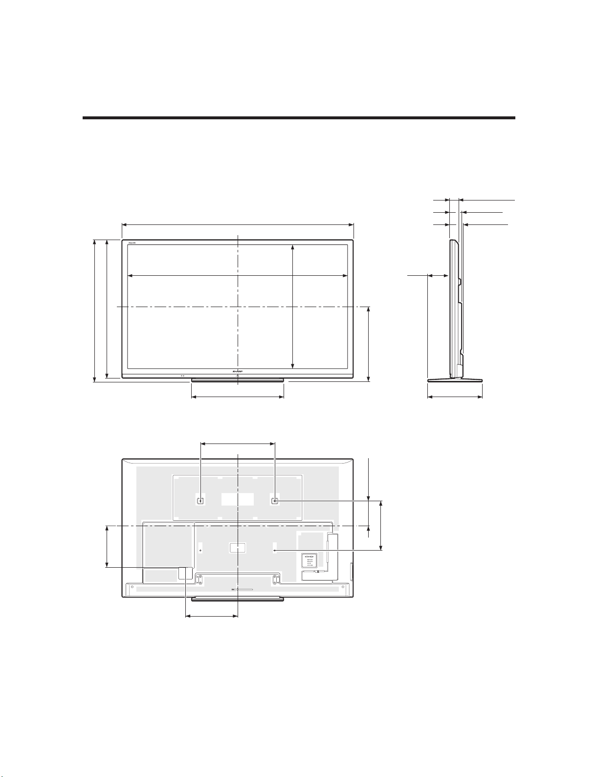
CHAPTER 3. DIMENSIONS
[1] DIMENSIONS
Dimensional Drawings
LC-80LE632U
Service Manual
Unit: inch (mm)
(1145)
32
/
3
45
(1112)
32
/
25
43
6947/64(1771.20)*
735/16(1862)
71/
1
1
64
/
15
39
(996.30)*
(609)
64
/
63
(179)
16
23
291/32(737) 173/32(434)
235/8(600)
(200)
8
/
7
7
231/64(63)*
31/2(89)
329/32(99)
2
(336)
64
/
15
13
1637/64(421)
*1
Active area/Área activa/Zone active
*2
Thinnest part/Parte más delgada/Partie la plus mince
3 – 1
(400)
4
/
3
15
Page 12
LC-80LE632U
LC80LE632U
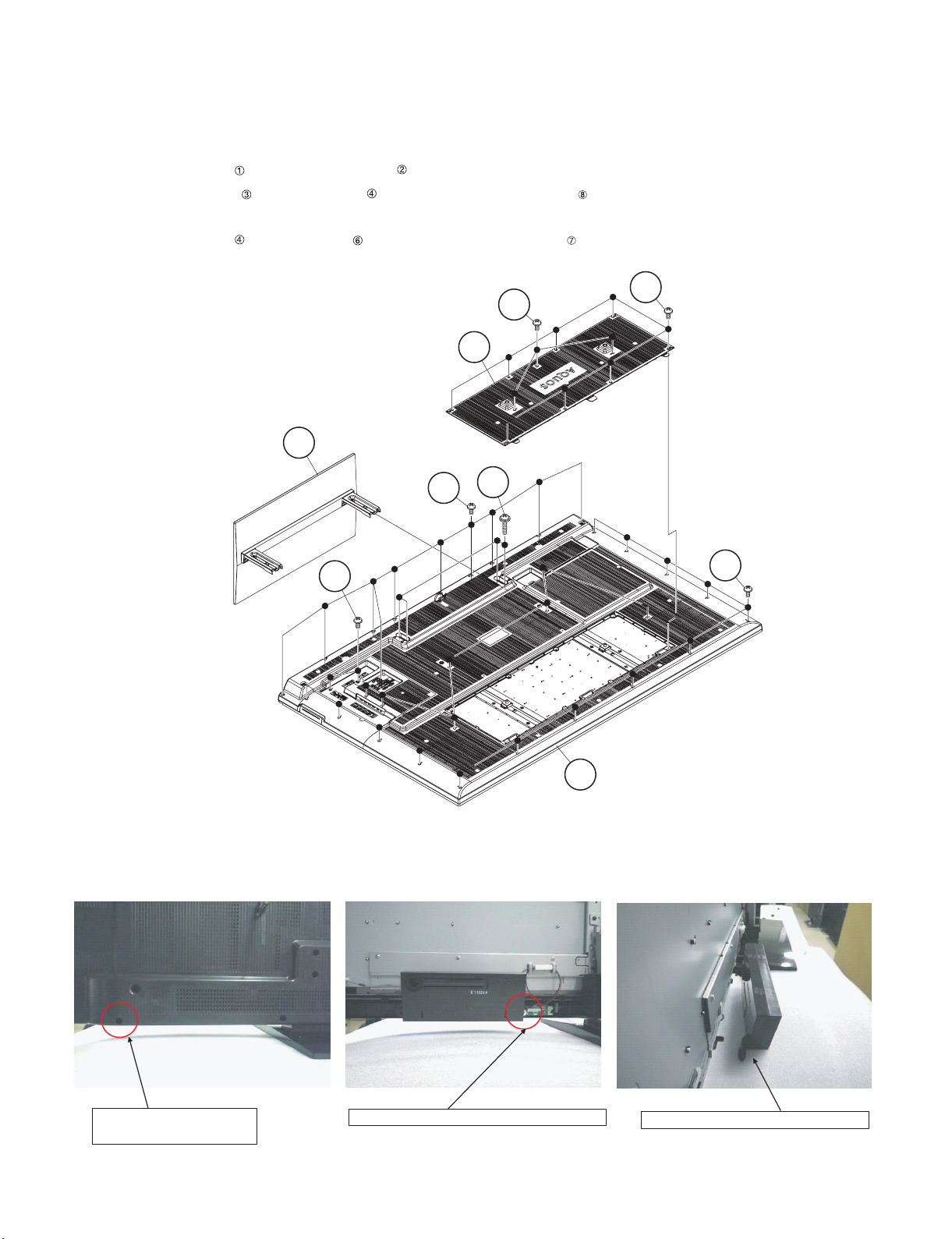
CHAPTER 4. REMOVING OF MAJOR PARTS
Service Manual
[1] REMOVING OF MAJOR PARTS
1. Removing of Stand Unit and Rear Cabinet Ass’y.
1. Remove the 4 lock screws and detach the Stand Unit .
2. Remove the 10 lock screws and 26 lock screws and detach the Rear Cabinet Ass’y .
* How to separate the Rear Cabinet Cover.
Remove the 3 lock screws and 8 lock screws and detach the Rear Cabinet Cover .
4
7Rear Cabinet Cover
2Stand Unit
6
3
4
[Precautions when mounting and removing the rear cabinet]
Therefore, it does not come away completely, but only one side can come off.
1
4
Rear Cabinet Ass'y
8
Tighten together with the
Rear Cabinet Ass'y.
Fix with the 80" LCD Panel Module Unit.
4 – 1
Only one side (outer) can come off.
Page 13
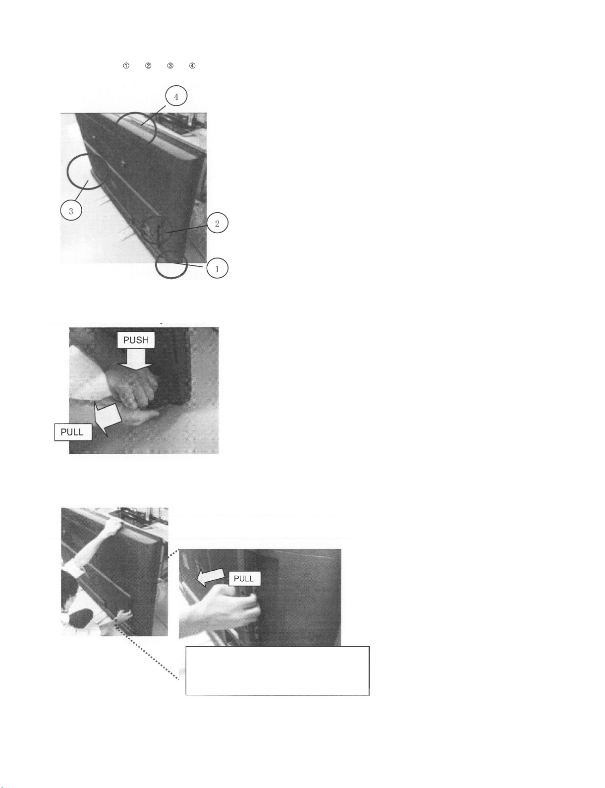
[How to remove Rear Cabinet Ass’y]
* Please do following works by 2 persons
Do following works as → → →
1) Please grasp the swelling of a speaker and pull back with pushing down.
Remove one hook under an operation.
LC-80LE632U
2) Put a hand in terminal area and pulls back, and the other hand holds top side of TV set.
Remove all-right hand side hook.
2WVCJCPFDGVYGGPVGTOKPCNCPINGCPF4GCT
%CDKPGV#UU[CPFRWNNUVJGODCEM
4 – 2
Page 14
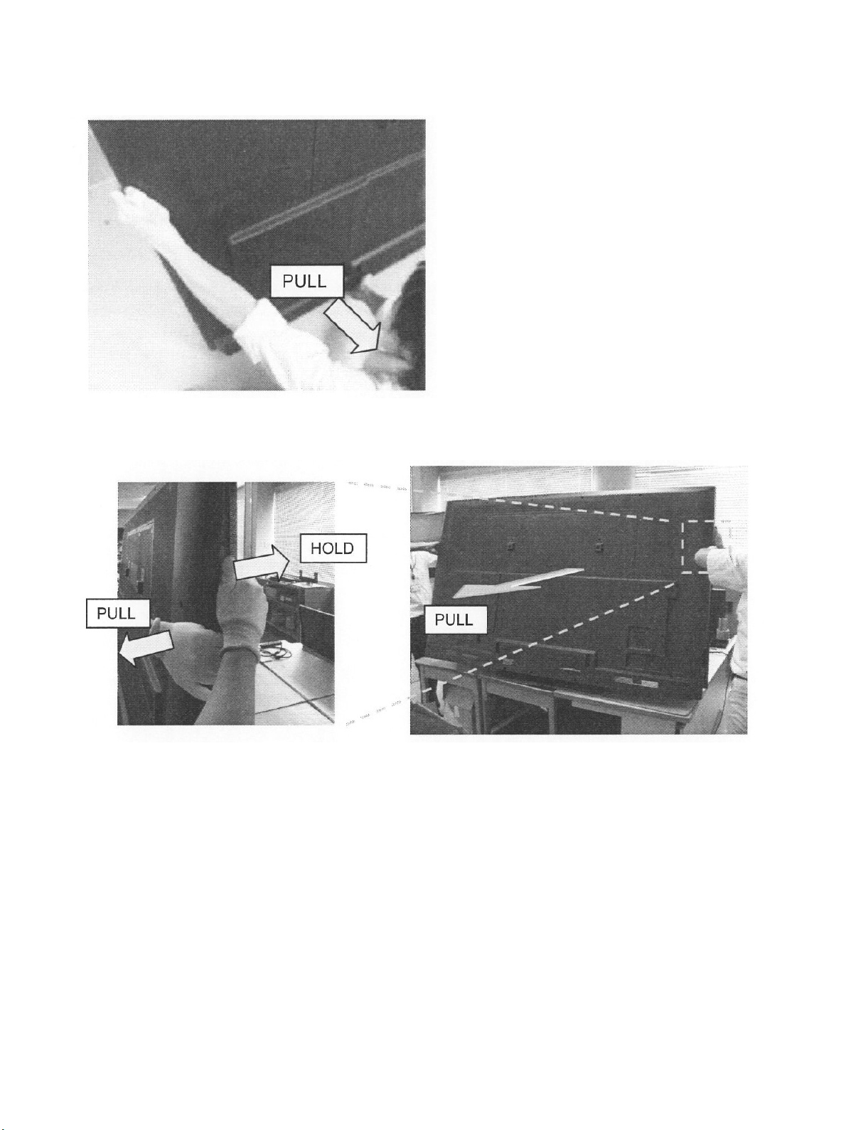
LC-80LE632U
3) Hold left side of TV set by one hand, and put the other hand between bottom cover and Rear Cabinet Ass’y.
And pull Rear Cabinet Ass’y.
Remove all-left hand side hook.
4) Two persons stand on the both sides of TV SET, and have a Front Cabinet Ass’y and a Rear Cabinet Ass’y by each hand.
Two persons pull a Rear Cabinet Ass’y horizontally back, simultaneously and remove it.
4 – 3
Page 15
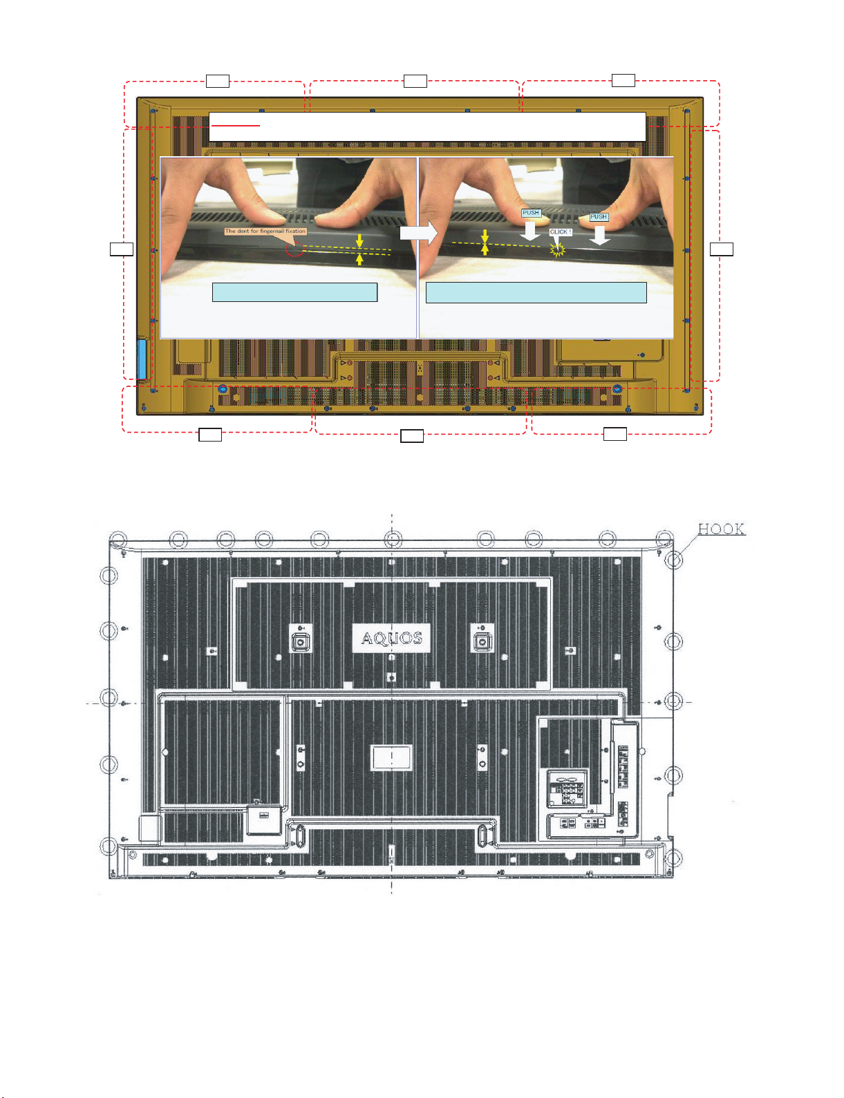
[Precautions for assembly]
Push
Push
Push
Push
Push
Push
Push
Push
CAUTION
Set it so that there may not be a clearance between Front Cabinet Ass'y and Rear Cabinet Ass'y.
LC-80LE632U
There is a gap without the fingernail fitting
in completely only when covering with Rear Cabinet Ass'y.
(Front Cabinet Ass’y/Rear Cabinet Ass’y fingernail fixation place)
The fingernail is surely fixed when Rear cabinet Ass'y is
firmly pushed, and the gap disappears.
4 – 4
Page 16

LC-80LE632U
2. Removing of Speaker (L/R) and KEY Unit.
1. Disconnect the SP wire.
2. Remove the 2 lock screws and detach the Speaker (L) , Speaker (R) .
3. Disconnect the RC wire.
4. Detach the KEY Unit Ass’y .
5. Disconnect the KM wire.
6. Remove the 2 lock screws and detach the Key Button from Key Button Cover .
7. Detach the KEY Unit from Key Button .
MAIN Unit
4
KEY Unit Ass'y
[SP]
5
7
KEY Unit
[RC]
8
[SP]
31Speaker (R) 2
Speaker (L)
[KM]
6 Key Button
1
[How to remove KEY Unit Ass’y]
1) When you remove KEY Unit Ass’y, please be sure to remove harness from WH, and to hold the bottom of KEY Unit Ass’y.
Key Button
Cover
4 – 5
Page 17

3. Removing of Connectors, 80” LCD Panel Module Unit Ass’y.
1. Disconnect the following connectors from the MAIN Unit. (LV, PD, Cl, UB)
2. Disconnect the following connectors from the POWER/DRIVE Unit. (L1, L2, PD)
3. Disconnect the following connectors from the LCD Control Unit. (PL, LW)
4. Remove the 27 Hooks and detach the 80 LCD Panel Module Unit Ass’y .
5. Detach the 2 Bottom cover .
Hock
LC-80LE632U
Hock
[L1] [L2]
POWER/DRIVE Unit
[PD]
Hock
[PL]
LCD
Control
Unit
2Bottom cover
MAIN Unit
[PD]
Hock
1 80" LCD Panel
Module
Unit Ass'y
[LW]
MAIN Unit
[LV]
[CI]
[UB]
4 – 6
Page 18

LC-80LE632U
4. Removing of LCD CONTROL Unit, MAIN Unit, POWER/DRIVE Unit.
1. Remove the 2 Connecting Cords , 2 Ferrite Cores , 6 lock screws and detach the LCD CONTROL Unit .
2. Remove the 5 lock screws and detach the Shield (MAIN Unit) .
3. Remove the 3 lock screws and detach the MAIN Unit and Terminal Angle (Bottom) .
4. Remove the 6 lock screws and detach the POWER/DRIVE Unit .
5. Remove the 12 lock screws and detach the 2 Stand Angles .
6. Remove the 16 lock screws and detach the 4 VESA Angle Ass’ys .
POWER/
DRIVE
Unit
Ass'y
Ass'y
Stand Angle
11
14
15VESA Angle
14
15VESA Angle
4
13
12
3
10
LCD
Control
Unit
12
2 Ferrite
Core
1 FFC
14
15 VESA Angle Ass'y
14
15 VESA Angle Ass'y
13
Stand
Angle
5
80" LCD Panel
Module Unit
MAIN Unit
8
7
9
Terminal
Angle
(Bottoom)
6
Shield
(MAIN Unit)
4 – 7
Page 19

5. Removing of R/C OPC Unit, ICON Unit, WiFi Unit.
1. Detach the R/C OPC Unit .
2. Disconnect the RC wire.
3. Detach the ICON Unit .
4. Disconnect the CI wire.
5. Detach the WiFi Unit .
6. Disconnect the UB wire.
Front Cabinet Ass'y
LC-80LE632U
[CI]
[UB]
[RA]
3ICON Unit 2 WiFi Unit 1 R/C OPE Unit
4 – 8
Page 20

LC-80LE632U
[2] The location putting on the heat measure sheet
1. MAIN PWB Unit
PSPAZC741WJKZ
4 – 9
Page 21

LC-80LE632U
[3] Precautions for assembly
1. Points to be checked and precautions when servicing the unit
Mount the main PWB Ass’y on the backlight chassis and check that the EMI-prevention parts are not peeled and twisted from the access holes. (The
EMI-prevention parts, conductive nonwoven fabric gaskets, must be seen from the access holes.)
[Countermeasure]
Attach the conductive nonwoven fabric gaskets on the shielded case on the main PWB.
PMLT-A679WJQZ
PMLT-A678WJQZx2pcs
Attach the conductive nonwoven fabric gasket on the RF terminal angle.
(PMLT-A680WJQZ)
State where the main PWB and shielded case are assembled
PSPAZC740WJZZ
Access hole
Access hole
4 – 10
Page 22

LC-80LE632U
The following is a drawing mounting the main PWB Ass’y on the backlight chassis. (The parts indicated by -> are the access holes for confirmation.)
(Main PWB Ass’y => State where the shielded case and RF terminal angle are mounted on the main PWB)
4 – 11
Page 23

LC-80LE632U
LC80LE632U
CHAPTER 5. ADJUSTMENT
Service Manual
[1] ADJUSTMENT PROCEDURE
The adjustment values are set to the optimum conditions at the factory before shipping. If a value should become improper or an adjustment is
required due to part replacement, make an adjustment according to the following procedure.
1. After replacement of any PWB unit and/or IC for repair, please note the following.
• When replacing the following units, make sure to prepare the new units loaded with updated software.
MAIN Unit: DKEYMF733FM49
• When replacing the LCD control PWB, perform the VCOM adjustment.
2. Upgrading of each microprocessor software
CAUTION: Never “POWER OFF” the unit when software upgrade is ongoing.
Otherwise the system may be damaged beyond recovery.
2.1. Software version upgrade
The model employs the following software.
• Main software (please use a software version after BSMK_632-732_xxx.USB).
• Monitor microprocessor software (please use a software version after BMSDMxxx.SMB.)
The main software, monitor microprocessor software can be upgraded by using a general-purpose USB Memory.
The followings are the procedures for upgrading, explained separately for the main software, monitor microprocessor software.
2.2. Main software version upgrade
2.2.1 Get ready before you start
• USB Memory of 128MB or higher capacity.
• PC running on Windows 98/98SE/ME/2000/XP operating system.
• USB Memory reader/writer or PC with a USB port.
• The file system of a USB memory is FAT. (FAT32 supports)
• Use the USB memory without other functions. (lock and memory reader...etc)
2.2.2 Preparations
To upgrade the main software, it is necessary to get ready the USB Memory for version upgrade before you start.
Follow the steps below and create the USB Memory for version upgrade.
1. Copy the file BSMK_632-732_xxx.USB for version upgrade to the root directory (folder) of the USB Memory.
NOTE: In the USB Memory drive, do not store other folders or unrelated files, or more than one file for version upgrade.
Now the USB Memory for version upgrade is ready.
5 – 1
Page 24

LC-80LE632U
2.2.3 How to upgrade the software
1. Unplug the AC cord.
2. Insert the USB Memory for version upgrade into the service socket.
3. Plug in the AC cord with power button pressed down.
4. After 5 seconds, unpress the power button.
5. After the unit startup, the system upgrade screen as shown below within 20-40 seconds.
Software Update
MAIN Version
SUB MICOM Version
PANEL EEPROM
IR MICOM Version
MAIN
SUB MICOM
PANEL EEPROM
IR MICOM
50%
NO DATA
NO DATA
OK
U1007071
㧙㧙㧙㧙㧙
㧙㧙㧙㧙
1.00
80LE632U
6. Even a single failure in the process will trigger the upgrade failure screen.
Software Update
MAIN Version
SUB MICOM Version
PANEL EEPROM
IR MICOM Version
UPGRADE FAILURE
MAIN
SUB MICOM
PANEL EEPROM
IR MICOM
Project ID
NO DATA
NO DATA
OK
㧙㧙㧙㧙㧙
㧙㧙㧙㧙㧙
㧙㧙㧙㧙
1.00
80LE632U
NOTE: In the event of a failure, repeat the upgrade process. If the process repeatedly fails, it is likely that the hardware need fixing.
7. Upon completion of the whole process, the upgrade success screen as shown below appears. You can check the new software version on this
screen. The version information appears after the upgrade is complete.
Software Update
MAIN Version
SUB MICOM Version
PANEL EEPROM
IR MICOM Version
UPGRADE SUCCESS
MAIN
SUB MICOM
PANEL EEPROM
IR MICOM
100%
NO DATA
NO DATA
OK
U1007071
㧙㧙㧙㧙㧙
㧙㧙㧙㧙
1.00
80LE632U
8. Unplug the AC cord and remove the USB Memory for version upgrade.
9. Now the software version upgrade is complete.
NOTE: When you are done with the software version upgrade, start the set, go to the top page of the adjustment process screen and check the main
software version information.
5 – 2
Page 25

LC-80LE632U
2.3. Monitor microprocessor software version upgrade
Create the USB memory for monitor microprocessor software version upgrade in the same manner as explained in the “Main software version
upgrade”.
Copy the file BSMK_632-732_xxx.USB and BMSDMxxx.SMB. (named temporarily) for monitor microprocessor software version upgrade to the USB
memory.
2.3.1 How to upgrade the software
1. Unplug the AC cord.
2. Insert the USB Memory for version upgrade into the service socket.
3. Plug in the AC cord with power button pressed down.
4. After 5 seconds, unpress the power button.
CAUTION: • The moment this operation is done, the upgrading of the monitor microprocessor software starts. While the upgrade is ongoing, never
5. After the unit startup, the upgrade starts. The power led will blink continuously. Also, an upgrade screen will be shown during a minor upgrade.
power off the unit. Otherwise the upgrade will fail and the system may be serious damaged beyond recovery (inability to start).
• After the monitor microprocessor software is upgraded, also perform the ‘Industry Init’.
Software Update
MAIN Version
SUB MICOM Version
PANEL EEPROM
IR MICOM Version
MAIN
SUB MICOM
PANEL EEPROM
IR MICOM
NO DATA
50%
NO DATA
OK
㧙㧙㧙㧙㧙
0.820
㧙㧙㧙㧙
1.00
80LE632U
6. If the upgrade fails, power led will stop blinking. Also, the upgrade failure screen will be shown if upgrade screen was shown at 5.
Software Update
MAIN Version
SUB MICOM Version
PANEL EEPROM
IR MICOM Version
UPGRADE FAILURE
MAIN
SUB MICOM
PANEL EEPROM
IR MICOM
NO DATA
SAME VERSION
NO DATA
OK
㧙㧙㧙㧙㧙
㧙㧙㧙㧙㧙
㧙㧙㧙㧙
1.00
80LE632U
NOTE: In the event of a transient failure, upgrade will be automatically retried up to three times. If the process repeatedly fails, hardware may be the
cause.
7. The upgrade success screen will be shown if upgrade screen was shown at 5.
Software Update
MAIN Version
SUB MICOM Version
PANEL EEPROM
IR MICOM Version
UPGRADE SUCCESS
MAIN
SUB MICOM
PANEL EEPROM
IR MICOM
NO DATA
100%
NO DATA
OK
㧙㧙㧙㧙㧙
0.820
㧙㧙㧙㧙
1.00
80LE632U
8. Unplug the AC cord and remove the USB Memory for version upgrade.
9. Now the software version upgrade is complete.
NOTE: When you are done with the software version upgrade, start the set, go to the top page of the adjustment process screen and check the mon-
itor microprocessor software version information and panel size information.
5 – 3
Page 26
LC-80LE632U
3. Entering and exiting the adjustment process mode
1) Before entering the adjustment process mode, the AV position RESET in the video adjustment menu.
2) While holding down the “VOL (–)” and “INPUT” keys at a time, plug in the AC cord of the main unit to turn on the power.
The letter “<K>” appears on the screen.
3) Next, hold down the “VOL (–)” and “CH ( )” keys at a time.
(The “VOL (–)” and “CH ( )” keys should be pressed and held until the display appears.)
Multiple lines of blue characters appearing on the display indicate that the unit is now in the adjustment process mode.
When you fail to enter the adjustment process mode (the display is the same as normal startup), retry the procedure.
4) To exit the adjustment process mode after the adjustment is done, unplug the AC cord from the outlet to make a forced shutdown. (When the
power was turned off with the remote controller, once unplug the AC cord and plug it again. In this case, wait 10 seconds or so before plugging.)
CAUTION: Use due care in handling the information described here lest your users should know how to enter the adjustment process mode. If the
settings are tampered in this mode, unrecoverable system damage may result.
4. Remote controller key operation and description of display in adjustment process mode
1) Key operation
Remote controller key Main unit key Function
CH ( / )
CH ( / )
VOL (+/–) VOL (+/–) Changing a selected item setting (+1/ –1)
Cursor (UP/DOWN) ————— Turing a page (PREVIOUS/NEXT)
Cursor (LEFT/RIGHT) ————— Changing a selected line setting (+10/ –10)
INPUT ————— Input switching (toggle switching)
ENTER ————— Executing a function
*Input mode is switched automatically when relevant adjustment is started so far as the necessary input signal is available.
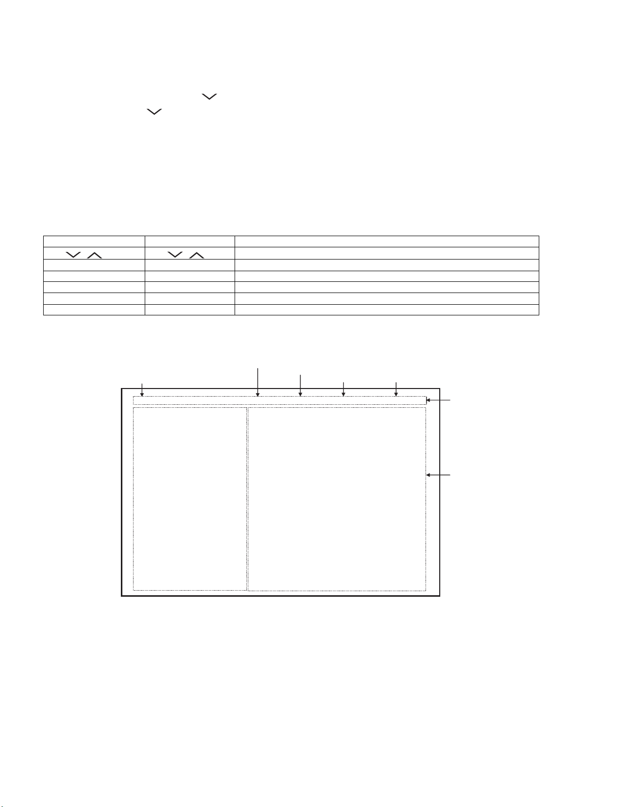
2) Description of display
Moving an item (line) by one (UP/DOWN)
(1) Current page/
Total pages
1/26 INPUT4 AUTO USA 80_UNDER
MAIN Version
BOOT Version
Monitor / Monitor BOOTVersion
T-CON Version / LED CON Version
NETFLIX ESN
WIDEVINE DEVICE ID
FRC Version
TOUCH SENSOR/IR Micom Version
TEMPERATURE 73
LAMP ERROR
MONITOR ERR CAUSE
NORMAL STANDBY CAUSE
ERROR STANDBY CAUSE
(2) Current selected input
(3) Current color system
1.04 (U 2010/07/07 1 A)
BSMKxxx
1.02 / 1.00
201006162D60250101 / FC
ERR
100531010000003D
201006162D60250101 / 010000000000000048
B0079022310 / 1.00
0
1) 11 B00000041:17 2) 11 B00000041:13
3) 11 B00000040:36 4) 11 B00000040:35
0
00000
(4) Destination
(5) LCD Panel size/Speaker type
(6) Adjustment
process menu
header
(7) Parameters
5 – 4
Page 27

LC-80LE632U
5. List of adjustment process mode menu
The character string in brackets [ ] will appear as a page title in the adjustment process menu header.
Page Line Item Description Remarks (adjustment detail, etc.)
1 1 MAIN Version Main software version
2BOOT Version
3 Monitor / Monitor BOOT Version Monitor and monitor boot software version
4 T-CON Version / LED CON Version LCD controller software version
5 NETFLIX ESN
6 WIDEVINE DEVICE ID
7 FRC Version
8 TOUCH SENSOR/IR Micom Ver-
sion
9 TEMPERATURE Panel temperature
10 LAMP ERROR Number of termination due to lamp error
11 MONITOR ERR CAUSE
12 NORMAL STANDBY CAUSE Refer to *1 under the list for details
13 ERROR STANDBY CAUSE Refer to *2 under the list for details
2 1 INDUSTRY INIT Initialization to factory settings
2 INDUSTRY INIT(-Public)
3 PUBLIC MODE Public mode
4 Center Acutime Accumulated main operation time
5 RESET Reset
6 Backlight Acutime Accumulated monitor operation time
7 RESET Reset
8 LAMP ERROR RESET Reset LAMP ERROR
9 VIC XPOS X-coordinate setting for VIC READ
10 VIC YPOS Y-coordinate setting for VIC READ
11 VIC COLOR Collected color data setting for VIC READ
12 VIC SIGNAL TYPE Signal type setting for VIC READ
13 VIC READ Picture level acquisition function Level appears in green on the upper right
3 1 N358 MAIN ADJ(INPUT2) CVBS and TUNER signal level adjustment
2 N358 MAIN ADJ(INPUT2) CVBS signal level adjustment
3 TUNER DAC ADJ TUNER signal level adjustment
4 N358 CONTRAST A_GAIN
5 N358 CONTRAST D_GAIN
6 N358 CONTRAST OFFSET
7 TUNER CONTRAST A_GAIN
8 TUNER CONTRAST D_GAIN
9 TUNER CONTRAST OFFSET
4 1 TUNER VCHIP TEST(69ch) Tuning test and VCHIP test (69ch)
2 TUNER VCHIP TEST(7ch) Tuning test and VCHIP test (7ch)
3 TUNER VCHIP TEST(10ch) Tuning test and VCHIP test (10ch)
4 TUNER VCHIP TEST(15ch) Tuning test and VCHIP test (15ch)
5 INSPECT USB TERM
6 HDMI EDID WRITE
7 HDMI CEC TEST
5 1 COMP15K ADJ(INPUT1) Component 15K picture level adjustment (main)
2 COMP15K Y A_GAIN
3 COMP15K Cb A_GAIN
4 COMP15K Cr A_GAIN
5 COMP15K Y OFFSET
6 COMP15K Cb OFFSET
7 COMP15K Cr OFFSET
6 1 COMP33K ADJ(INPUT1) Component 33K picture level adjustment (main)
2 COMP33K Y A_GAIN
3 COMP33K Cb A_GAIN
4 COMP33K Cr A_GAIN
5 COMP33K Y OFFSET
6 COMP33K Cb OFFSET
7 COMP33K Cr OFFSET
5 – 5
Page 28

LC-80LE632U
Page Line Item Description Remarks (adjustment detail, etc.)
7 1 ANALOG RGB ADJ Analog RGB picture level adjustment
2 R A_GAIN
3 G A_GAIN
4 B A_GAIN
5 R OFFSET
6 G OFFSET
7 B OFFSET
8 1 VCOM ADJ VCOM adjustment value
9 1 LEV1 Standard value 1 Adjustment gradation setting.
2 LEV2 Standard value 2
3 LEV3 Standard value 3
4 LEV4 Standard value 4
5 LEV5 Standard value 5
6 LEV6 Standard value 6
10 1 MG1R WB adjustment Point 1, R adjustment value Parameter for six-point adjustment
2 MG1G WB adjustment Point 1, G adjustment value
3 MG1B WB adjustment Point 1, B adjustment value
4 MG1Y WB adjustment Point 1, Y adjustment value
5 MG2R WB adjustment Point 2, R adjustment value
6 MG2G WB adjustment Point 2, G adjustment value
7 MG2B WB adjustment Point 2, B adjustment value
8 MG2Y WB adjustment Point 2, Y adjustment value
9 MG3R WB adjustment Point 3, R adjustment value
10 MG3G WB adjustment Point 3, G adjustment value
11 MG3B WB adjustment Point 3, B adjustment value
12 MG3Y WB adjustment Point 3, Y adjustment value
11 1 MG4R WB adjustment Point 4, R adjustment value Parameter for six-point adjustment
2 MG4G WB adjustment Point 4, G adjustment value
3 MG4B WB adjustment Point 4, B adjustment value
4 MG4Y WB adjustment Point 4, Y adjustment value
5 MG5R WB adjustment Point 5, R adjustment value
6 MG5G WB adjustment Point 5, G adjustment value
7 MG5B WB adjustment Point 5, B adjustment value
8 MG5Y WB adjustment Point 5, Y adjustment value
9 MG6R WB adjustment Point 6, R adjustment value
10 MG6G WB adjustment Point 6, G adjustment value
11 MG6B WB adjustment Point 6, B adjustment value
12 MG6Y WB adjustment Point 6, Y adjustment value
13 MG6Y OFFSET
12 1 MODE SELECT Gamma adjustment
2 POS SELECT
3POS MIN
4POS MID1
5POS MID2
6POS MID3
7POS MID4
8POS MID5
9POS MID6
10 POS MAX
13 1 CD MIN
2 CD MID1
3 CD MID2
4 CD MID3
5 CD MID4
6 CD MID5
7 CD MID6
8 CD MAX
* This item is for review by engineers and not
actually used.
5 – 6
Page 29

LC-80LE632U
Page Line Item Description Remarks (adjustment detail, etc.)
14 1 CALC
2 RESET
3VAL1
4VAL2
5VAL3
6VAL4
7VAL5
8VAL6
15 1 MONITOR TIME OUT
2 MONITOR MAX TEMP
3 MONITOR ERROR CAUSE RESET
16 1 LCD TEST PATTERN
2 LCD TEST PATTERN1
3 LCD TEST PATTERN2
4 LCD TEST PATTERN3
5 LCD TEST PATTERN4
6 TV TEST PATTERN 1
7 TV TEST PATTERN 2
17 1 T-CON VERSION EXT.1 PRIMROSE 2D Version
2 T-CON VERSION EXT.2 PRIMROSE 3D Version
3 T-CON VERSION EXT.3 Blank (Not Use)
4 T-CON VERSION EXT.4 Blank (Not Use)
18 1 READ/WRITE
2 SLAVE ADDRESS
3 RESISTER ADDRESS UPPER
4 RESISTER ADDRESS LOWER
5 WRITE DATA UPPER
6WRITE DATA LOWER
7 READ DATA UPPER
8 READ DATA LOWER
19 1 POWER LED BRIGHTNESS
2 MENU LED BRIGHTNESS
3 INPUT LED BRIGHTNESS
4 CH UP LED BRIGHTNESS
5 CH DOWN LED BRIGHTNESS
6 VOL UP LED BRIGHTNESS
7 VOL DOWN LED BRIGHTNESS
8 LOGO LED BRIGHTNESS
9 ICON LED BRIGHTNESS
10 ICON LED BRIGHTNESS
(STANDBY)
11 3D LED BRIGHTNESS
20 1 POWER KEY SENSITIVITY
2 MENU KEY SENSITIVITY
3 INPUT KEY SENSITIVITY
4 CH UP KEY SENSITIVITY
5 CH DOWN KEY SENSITIVITY
6 VOL UP KEY SENSITIVITY
7 VOL DOWN KEY SENSITIVITY
21 1 KEY STRENGTH GET MODE
2 POWER KEY STRENGTH
3 MENU KEY STRENGTH
4 INPUT KEY STRENGTH
5 CH UP KEY STRENGTH
6 CH DOWN KEY STRENGTH
7 VOL UP KEY STRENGTH
8 VOL DOWN KEY STRENGTH
22 1 CROSSTALK ADJ MODE
2 CROSSTALK TH1
3 CROSSTALK TH2
4 CROSSTALK TH3
5 CROSSTALK TH4
6 CROSSTALK GAIN1
7 CROSSTALK GAIN2
8 CROSSTALK GAIN3
5 – 7
Page 30

LC-80LE632U
Page Line Item Description Remarks (adjustment detail, etc.)
23 1 WIFI SSID 2.4GHz Set AP SSID
2 WIFI SSID 5GHz Set AP SSID
3 WIFI RSSI 2.4GHz Set RSSI threshold
4 WIFI RSSI 5GHz Set RSSI threshold
5 WIFI TIME 2.4GHz Set Time Out
6 WIFI TIME 5GHz Set Time Out
7 WIFI RSSI TEST Execute test
8 WIFI RSSI RESULT Display test result
24 1 KEY LOCK (1217)
2 KOUTEI AREA ALL CLEAR
3 A MODE AREA CLEAR
4 BACKUP AREA CLEAR
5 B MODE AREA CLEAR
6EXECUTION
25 1 ERROR STANDBY CAUSE1
2 ERROR STANDBY CAUSE2
3 ERROR STANDBY CAUSE3
4 ERROR STANDBY CAUSE4
5 ERROR STANDBY CAUSE5
6 ERROR STANDBY CAUSE RESET
26 1 EEP SAVE Writing setting values to EEPROM
2 EEP RECOVER Reading setting values from EEPROM
3MODEL NAME
4 PANEL SIZE
5 SETTING FOR ADJ
6 PANEL LIMIT
7 PANEL RANGE LIMIT
8 SHORT CHECK MODE
9 SHORT CHECK CURRENT
10 CURRENT SW
11 TEST NETWORK UPDATE
5 – 8
Page 31

LC-80LE632U
*1 Details of P1.12 (NORMAL STANDBY CAUSE)
When TV set is powered off due to normal use or product specification, the last cause will be recorded.
The code, character string and description for the standby cause are below.
If you power off by remote, the cause will not be recorded.
Code Character string Description
2 NO_OPERT No operation off
3 NO_SIGNA No signal off
6 SLEEP_TM Off timer
8 OFF_232C Command from RS232C
*2 Details of P1.13 (ERROR STANDBY CAUSE)
When TV set is powered off due to any anomaly detection, the past 5 causes will be recorded.
You can confirm the time those causes occurred and character string in the adjustment process mode menu. (Page 25/26)
The time is accumulated total after TV set is powered on, and the value corresponds to “Center Acutime” in the adjustment process mode menu.
The code, character string and description for the standby cause are below.
If no error has occurred, the code is 0 and the character string is “NO RECORD”.
Code Character string Description
1A E_MONITR Monitor trouble detected
1B E_CVICBT Driver boot error
22 E_TCNERR Software abnormality of LCD controller
48 E_MRESET Failure of resetting menu settings (Initial Setup - Reset)
50 E_TCNF_S T-CON FPGA status error
54 E_TCON_E T-CON hung-up
Monitor ERR STBY table
Outline: Communication/Power failure detected by the monitor microcomputer is stored in EEPROM, and last 4 abnormal can
be confirmed in the Process mode A.
Location: Page 1 of the process mode A: MONITOR ERR CAUSE. “0” if there is no error. It is cleared to 0 on the last page of
the process mode A.
Display Error description
02 Initial communication from the main CPU is not received. Check UART bus between main CPU and sub CPU.
03 Only the initial communication is received.
04 Until panel information request reception
05 Until initialization completion reception
06 Until version notification transmission
07 Until start-up information notification transmission
08 Until start-up information response reception
09 Until time-out setting reception
0A Request time-out
0B Restart time-out during the beginning of time acquisition start-up
0C Ending sequence time-out
0D Preset start-up time-out during completion
0E Download, start-up time-out
0F Time acquisition time-out
11 Regular communication time-out
16 Backlight error See p.6-5
1A Monitor temperature failure - Check TV setting environment
- Check the other monitor (ref No.)
1E DET_13V failure Check 13V power line.
1F DET_D3V3 failure Check D3V3 power line.
20 ERROR_3D (3D-PWB) failure Check 3D-PWB
21 DET_PNLxxV failure Check T-CON power line
23 Error standby request from the main CPU Check ERROR STANDBY CAUSE (p.5-8)
5 – 9
Page 32
LC-80LE632U
6. Special features
* STANDBY CAUSE (Page 1/26)
Display of a cause (code) of the last standby
The cause of the last standby is recorded in EEPROM whenever possible.
Checking this code will be useful in finding a problem when you repair the troubled set.
* EEP SAVE (Page 26/26)
Storage of EEP adjustment value
* EEP RECOVER (Page 26/26)
Retrieval of EEP adjustment value from storage area
7. Writing the microprocessor software
7.1. Writing the main microprocessor software and monitor microprocessor software
(Main PWB: QPWBXF733WJN2)
Adjustment item Adjustment conditions Adjustment procedure
1 Writing the main micropro-
cessor software and monitor microprocessor software
<Main PWB>
Checker process
Checking the file version
Checking the USB memory
1) Using the checker, connect the specified writing tool to the SC8452 (TL8461 TL8475).
2) Using the checker, connect the USB memory to the J9502 (TL9503, TL9506 -
9508).
3) Apply the specified voltage to the PWB and boot it up with the tool connected.
4) Send the software writing start command via RS232C.
5) Send the writing status check command and confirm the response of OK. Then
turn off the power.
CAUTION: When the USB memory is not inserted or reading error occurs, nothing
is written.
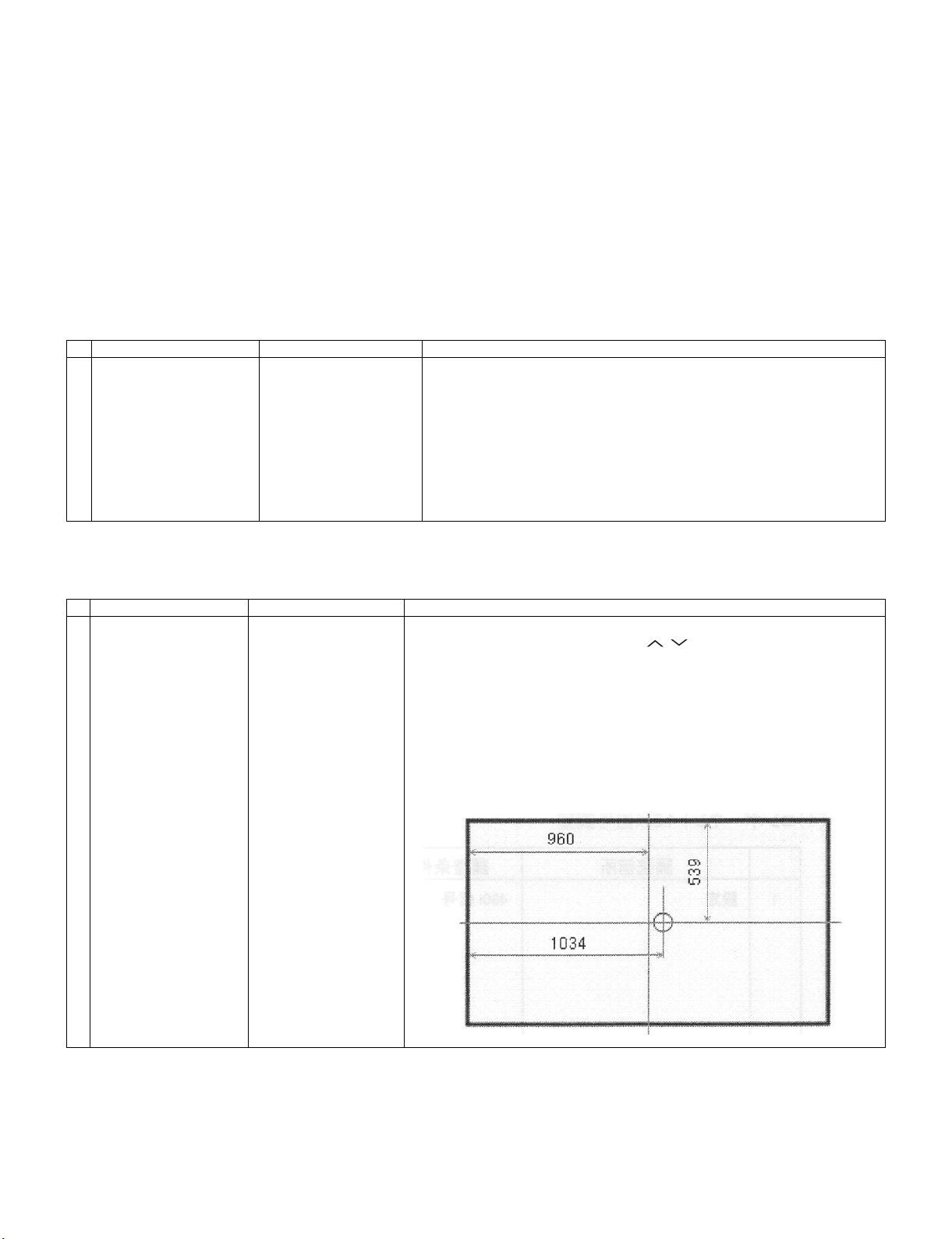
8. Signal adjustment
8.1. LCD section adjustment [LCD module adjustment]
Adjustment item Adjustment conditions Adjustment procedure
1 Opposite bias adjustment
(LCD module adjustment
item)
Adjustment in the adjustment position shown in
the right
1) Enter the process mode using the process adjustment remote control.
2) Select [VCOM ADJ] using the Channel / keys on the remote control.
3) Press the Enter key to check that the pattern for adjustment is displayed.
4) Make adjustment so that the flicker located in the center of the screen is mini-
5) If the optimum condition is obtained in step 4, press the Enter key to turn off the
CAUTION: * Make adjustment with no ANT signal (since the brightness is changed
[Adjustment position]
adjustment position X=1034, y=539
mized using the Volume +/- keys on the remote control.
pattern.
by the active backlight).
5 – 10
Page 33

LC-80LE632U
8.2. Image adjustment
8.2.1 Device check
Before adjustment, check that the adjustment jig and signal source are set for Sharp LCD US.
Signal generator level adjustment check (Adjust to the standard value level.)
• Composite signal: 0.714Vp-p ± 0.02Vp-p (Pedestal to white)
• 15K component signal: Y level: 0.714Vp-p± 0.02Vp-p (Pedestal to white)
PB/PR level: 0.7Vp-p ± 0.02Vp-p
• 33K component signal: Y level: 0.7Vp-p ± 0.02Vp-p (Pedestal to white)
PB/PR level: 0.7Vp-p ± 0.02Vp-p
• Analog RGB: RGB level: 0.7Vp-p ± 0.02Vp-p (Pedestal to white)
8.2.2 Process mode
Adjustment point Adjustment conditions Adjustment procedure
Process mode Enter the process adjustment mode using the process adjustment remote control.
8.2.3 Composite N358 signal/tuner adjustment
Adjustment point Adjustment conditions Adjustment procedure
1 Setting N358 signal
US-10ch
• Send the N358 color bar (color saturation: 75%) signal to the composite input.
• Send the in-house signal (use US-10ch) to TUNER.
[Video input signal] [In-house US-10ch]
Color saturation: 75%
0% black
2 Automatic adjustment exe-
cution
100% white 100% white
Point the cursor to [ N358 ALL ADJ(INPUT2)] and press the [Enter] key.
The adjustment is complete when [ N358 ALL ADJ(INPUT2) OK] is displayed.
8.2.4 Component 15K signal adjustment
Adjustment point Adjustment conditions Adjustment procedure
1 Setting 480i signal • Send the 100% color bar signal to the component input.
2 Automatic adjustment exe-
cution
Color saturation: 100%
100% white 0% black
Point the cursor to [ COMP15K ADJ(INPUT1)] and press the [Enter] key.
The adjustment is complete when [ COMP15K ADJ(INPUT1) OK] is displayed.
480i
100% color bar
5 – 11
Page 34

LC-80LE632U
8.2.5 Component 33K signal adjustment
Adjustment point Adjustment conditions Adjustment procedure
1 Setting 1080i signal • Send the 100% color bar signal to the component input.
2 Automatic adjustment exe-
cution
8.2.6 Analog RGB signal adjustment
Adjustment point Adjustment conditions Adjustment procedure
1 Setting Signal: XGA
(1024x768) 60Hz
SYNC: HV separate
2 Automatic adjustment exe-
cution
8.2.7 Tuner/V-CHIP adjustment
Adjustment point Adjustment conditions Adjustment procedure
1 Setting NTSC RF signal
US-7(AIR)ch
2 Automatic adjustment exe-
cution
Color saturation: 100%
100% white 0% black
Point the cursor to [ COMP33K ADJ(INPUT1)] and press the [Enter] key.
The adjustment is complete when [ COMP33K ADJ(INPUT1) OK] is displayed.
• Send the 100% color bar signal to the PC input.
100% white 0% black
Point the cursor to [ ANALOG RGB ADJ] and press the [Enter] key.
The adjustment is complete when [ ANALOG RGB ADJ OK] is displayed.
• Send the NTSC signal to the RF antenna input.
Point the cursor to [ VCHIP TEST(*07ch)] and press the [Enter] key.
(* Adjust the selected channel to the in-house signal.)
The adjustment is OK when [ VM-OK] is displayed in green.
(NG when VM-NG is displayed in red.)
1080i
100% color bar
XGA (1024x768)
100% color bar
5 – 12
Page 35
LC-80LE632U
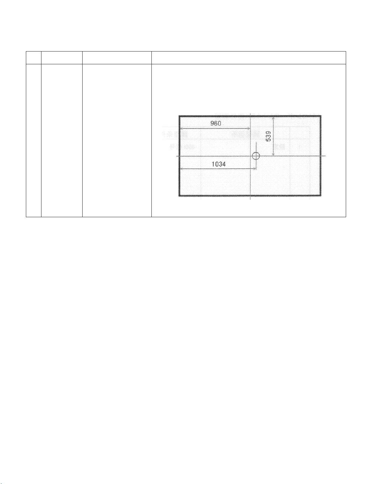
9. White balance adjustment
9.1. White balance adjustment (For details about the adjustment procedure, refer to “Kameyama Model Integrated Monitor
WB Adjustment Specification V1.92”.)
Adjustment
point
1 Setting 1) Set the unit to the following conditions.
Adjustment conditions Adjustment procedure
AV MODE: [DYNAMIC]
Backlight: +16
Active Backlight: OFF
Aging Time: Min. 60 minutes
2) Connect the unit with the white balance adjustment jig.
Note 1: The screen adjustment point is located in x=1034pt and y=539pt.
Note 2: For the WB adjustment, perform teaching and adjustment after turning off the
unevenness cancellation by the RS232C command.
5 – 13
Page 36

LC-80LE632U
Adjustment
point
2 Automatic
adjustment execution
Adjustment conditions Adjustment procedure
[Command]
Process mode
KRSW0001
KKT10037
Setting
KY0F0000
0SDS0001
SBSL0016
Multi-point adjustment mode
MREN0000
MSET0011
Point 6
LEV60232
MG6G****
MG6B****
MG6R****
Point 5
LEV50201
MG5G****
MG5B****
MG5R****
Point 4
LEV40150
MG4G****
MG4B****
MG4R****
[Adjustment procedure]
1) Send the “adjustment process” code using the remote control.
2) Set the point 6 to the specified gradation, specify the strongest color as the fixed
color, and adjust the RGB so that it becomes the standard value through negative
adjustment.
3) Set the point 5 to the specified gradation, set the G correction value (804 x G value of
point 6/928) (fractions rounded off), and adjust the RB so that it becomes the standard value.
4) Set the point 4 to the specified gradation, set the G correction value (600 x G value of
point 6/928) (fractions rounded off), and adjust the RB so that it becomes the standard value.
5) Set the point 3 to the specified gradation, set the G correction value (448 x G value of
point 6/928) (fractions rounded off), and adjust the RB so that it becomes the standard value.
6) Set the point 2 to the specified gradation, set the G correction value (296 x G value of
point 6/928) (fractions rounded off), and adjust the RB so that it becomes the standard value.
7) Set the point 1 to the specified gradation, set the G correction value (1164 x G value
of point 6/928) (fractions rounded off), and adjust the RB so that it becomes the standard value.
8) Write the adjustment value by the MSET0003 command and turn off the AC power.
* RGB initial value of point 6: Set gradation 928
* RGB initial value of points 1 to 5: G correction value of each point
(At each point, make adjustment so that the remainder of the RGB adjustment value/
4 is equal.)
[Adjustment value]
* According to the “Standard settings” submitted by the Technical Department
[LC80LE632UN] teaching set
Teaching must be made with the unevenness cancellation off.
(Unevenness cancellation OFF command: MREN0000)
Point 3
LEV30112
MG3G****
MG3B****
MG3R****
Point 2
LEV20074
MG2G****
MG2B****
MG2R****
Point 1
LEV10041
MG1G****
MG1B****
MG1R****
Writing
MSET0003
5 – 14
Page 37

LC-80LE632U
Adjustment
point
Adjustment conditions Adjustment procedure
10. Key writing
10.1. EDID writing (Main PWB: QPWBXF733WJN2)
[Adjustment standard value]
Measuring instrument: [Minolta CA-210] Technical measuring instrument
Level Reference value Adjustment spec Inspection spec
Point 6 928
Point 5 804
Point 4 600
Point 3 448
Point 2 296
Point 1 164
Remarks Setting conditions for inspection
X=0.272
y=0.277
X=0.272
y=0.277
X=0.272
y=0.277
X=0.272
y=0.277
X=0.272
y=0.277
X=0.272
y=0.277
AV MODE: [DYNAMIC] (Reset)
Monochro: ON
Active Backlight: OFF
Aging Time: Min. 60 minutes
±0.0010 ±0.0020
±0.0010 ±0.0020
±0.0015 ±0.0030
±0.0020 ±0.0040
±0.0030 ±0.0060
±0.004 ±0.0080
Adjustment point Adjustment conditions Adjustment procedure
1 HDMI EDID writing
Analog RGB EDID writing
(Main PWB)
Process mode
Model discrimination check
1) Enter the process mode.
2) Point the cursor to [HDMI EDID WRITE] and press the [ENT]
key.
The writing is complete when [OK] is displayed.
(If not written, HDMI and Analog RGB does not function.)
CAUTION: Perform the data writing after setting the model discrimi-
nation. The data based on the model discrimination
information is recorded in EEPROM.
10.2. MAC key writing (MAIN PWB: QPWBXF733WJN2)
1. Write the MAC key data on IC8455 mounted on the main PWB.
2. Carry out thorough data management to avoid redundant writing of data.
If the IC where data is written is damaged, replace the PWB since only the IC cannot be changed.
10.3. NETFLIX/WMDRM key writing (MAIN PWB: QPWBXF733WJN2)
1. Write the NETFLIX/WMDRM key data on IC8401 mounted on the main PWB.
2. Carry out thorough data management to avoid redundant writing of data.
If the IC where data is written is damaged, replace the PWB since only the IC cannot be changed.
5 – 15
Page 38

LC-80LE632U
11. Factory setting
After completing the factory setting, pull out the AC cord to complete the setting.
CAUTION: Do not turn on the power after completing the factory setting. If the power is turned on, configure the factory setting again.
Adjustment point Adjustment conditions Adjustment procedure
1 Factory setting Complete the setting by
pulling out the AC cord.
12. Software version
1. Main microcomputer
BSMK_LE632-732_xxx_CHK.USB
BSMK_LE632-732_xxx.DAT
BSMK_LE632-732_xxxxxxx.PCC
2. Monitor microcomputer
BMSDMxxx.SMB
3. LCD Controller
CLOVER_20110210CB027001_WSRC_E618DE.ROM
• Point the cursor to [INDUSTRY INIT (+Cause)], set to “ON” using [+]/[-] of the [VOL]
key, and press the [ENT] key.
The version confirmation screen appears on the green screen. It is completed when
[SUCCESS] is displayed at the top.
(If error occurs, [ERROR] is displayed on the red screen.)
• Turn off the AC power.
The following items are initialized when configuring the factory setting.
1) User set value
2) Channel data (broadcasting frequency, etc.)
3) Password setting value
4) Operating time
5) Standby Cause
6) Auto installation flag
7) V-CHIP block setting value
5 – 16
Page 39

ޣ
LC80LE632U
CHAPTER 6. OVERALL WIRING DIAGRAM
[1] OVERALL WIRING DIAGRAM
J
I
H
LC-80LE632U
Service Manual
G
ޣACޤ
1˴3
ޣPDޤ
24
1
ޣSPޤ
1
ޣLVޤ
1
4
1 ˴˴24
ޣPDޤ
MAIN Unit
USB
HDMIHDMI
DKEYMF733FM49
HDMI
T-CON Unit
DUNTKF778FM12
180180
14
ޣPLޤ
ޣLW ޤ
1
ޣRCޤ
1
ޣCIޤ
1
1
ޣUBޤ
TUNER
ETHER
US
NET
B
KEY UNIT
HDMI
ޣKYޤ
1
4
DUNTKF800FM50
F
POWER/LED DRIVE Unit
E
D
C
B
RUNTKA903WJQZ
13
A
ޣCI
EMBLEM Unit
1
23
8
Rch㧦RSP-ZA539WJQZ
DUNTKF770FM02
1097654
16
ޣUB
WiFi Unit
RUNTKA810WJQZ
1311 191816151412 17
RA
15
R/C OPC Unit
DUNTKF494FM01
Lch 㧦RSP-ZA538WJQZ
6 – 1
Page 40

LC-80LE632U
— M E M O —
6 – 2
Page 41

PartsGuide
LC-80LE632U
PARTS GUIDE
No. S91T680LE632U
LCD COLOR TELEVISION
[1] PRINTED WIRING BOARD
ASSEMBLIES
[2] LCD PANEL MODULE UNIT
[3] CABINET PARTS
MODEL
CONTENTS
LC-80LE632U
[4] LCD PANEL MODULE UNIT
[5] SUPPLIED ACCESSORIES/
PACKING PARTS
[6] SERVICE JIGS (USE FOR
SERVICING)
Parts marked with " " are important for maintaining the safety of the set. Be sure to replace these
parts with specified ones for maintaining the safety and performance of the set.
This document has been published to be used
for after sales service only.
The contents are subject to change without notice.
Page 42

LC-80LE632U
NO. PARTS CODE
PRICE
RANK
[1] PRINTED WIRING BOARD ASSEMBLIES
N DKEYMF733FM49 X MAIN Unit
N DUNTKF494FM01 AG X R/C OPC Unit
N DUNTKF770FM02 AE X ICON Unit
N DUNTKF800FM50 AF X KEY Unit
N DUNTKF778FM12 N X LCD CONTROL Unit
N RUNTKA810WJQZ AZ X WIFI Unit
!
N RUNTKA903WJQZ N X POWER/DRIVE Unit
[2] LCD PANEL MODULE UNIT
N R1LK800D3GW10Z N X 80" LCD Panel Module Unit (LK800D3GW10Z)
NEW
MARK
PAR T
DELIVERY
DESCRIPTION
2
Page 43

[3] CABINET PARTS
2
40
40
41
2-7
7
2-6
30
2-1
2-2
2-4
37
2-5
2-3
38
19
19
36
29
35
39
9
4
4
9
39
18
1-3
6
1
1-2
1-5
1-4
5
8
41
14
1-7
1-6
1-1
18
28
33
23
20
24
21
20
10
22
25
18
31
32
39
3-1
3
3-2
3-2
3-1
3-2
3-1
3-2
3-1
18
12
11
14
11
14
13
34
27
16
C
D
SP
J
L2
L1
F
POWER/
DRIVE
Unit
PD
G
MAIN
Unit
PD
SP
CI
UB
PD
LW
J
KM
RA
KM
KEY
Unit
RA
UB
CI
R/C OPC
Unit
WiFi
Unit
ICON
Unit
E
PL
LW
FF
FF
H
LCD CONTROL
Unit
80" LCD Panel
Module Unit
C
D
G
H
F
E
L2
L1
PL
LC-80LE632U
3
Page 44

LC-80LE632U
NO. PARTS CODE
PRICE
RANK
NEW
MARK
PAR T
DELIVERY
[3] CABINET PARTS
1 CCABAC818WJ31 N X Front Cabinet Ass'y
1-1 Not Available - - Front Cabinet
1-2 Not Available - - R/C OPC Cover
1-3 HDECQB669WJ3A N X Decoration Plate
1-4 LHLDWA289WJKZ AC X Wire Holder
1-5 PSHEPB168WJKZ N X Diffusion Sheet
1-6 PSPAHC173WJZZ X Spacer, x2
1-7 TLABZD048WJZZ N X HDMI Label
2 CCABBC032WJ31 N X Rear Cabinet Ass'y
2-1 Not Available - - Rear Cabinet
2-2 Not Available - - Rear Cabinet Cover
2-3 HINDPE034WJSA X Terminal Indicator (Back)
2-4 HINDPE435WJSA X Terminal Indicator (Side)
2-5 HINDPE468WJSA X Terminal Indicator (Bottom)
2-6 XEBS830P08000 AA X Screw, x8
2-7 LHLDWA303WJKA AE X Cable Clamp
3 CANGKD398WJ31 N X VESA Angle Ass'y, x4
3-1 Not Available - - VESA Angle
3-2 Not Available - - VESA Shaft
4 GCOVAE164WJ3A X Bottom Cover, x2
5 GCOVAE251WJ3A N X Key Button Cover
6 HINDPE407WJZZ N X Energy Guide Label
7 HINDPE460WJSA N X Model Label
8 JBTN-A937WJ3A X Key Button
9 LANGKD290WJ3W X Stand Angle, x2
10 LANGKD292WJ3W X Terminal Angle (Bottom)
11 LHLDWA124WJKZ AC X Wire Holder, x4
12 LHLDWA138WJKZ AC X Wire Holder, x3
13 LHLDWA151WJKZ AB X Wire Holder, x2
14 LHLDWA175WJUZ AC X Wire Holder, x3
16 LHLDWA176WJUZ AC X Wire Holder, x2
18 LX-BZA207WJF7 AA X Screw, x20
19 LX-EZA069WJF7 AB X Screw, x2
20 PMLT-A678WJQZ X
21 PMLT-A679WJQZ X Gasket
22 PMLT-A680WJQZ X Gasket
23 PSLDMB762WJ3W X Shield (MAIN Unit)
24 PSPAZC740WJZZ X Spacer
25 PSPAZC741WJKZ X Spacer
27 QCNW-M361WJQZ N X Connecting Cord, x2 (80P:MDL-CPW)
28 QCNW-M368WJQZ N X Connecting Cord (LV)
29 QCNW-M373WJQZ N X Connecting Cord (SP)
30 QCNW-M374WJQZ N X Connecting Cord (PD)
31 QCNW-M375WJQZ N X Connecting Cord (CI)
32 QCNW-M376WJQZ N X Connecting Cord (UB)
33 QCNW-M377WJQZ N X Connecting Cord (RC)
34 RCORFA061WJZZ AG X Ferrite Core, x2
35 RSP-ZA538WJQZ X Speaker (L)
36 RSP-ZA539WJQZ X Speaker (R)
37 TLABNB037WJZZ X Serial Label (Back)
38 TLABNE225WJZZ N X Serial Label (Side)
39 XBPS830P06WS0 AA X Screw, x28
40 XBPS830P06WS0 AA X Screw, x26
41 XEBS830P12000 AA X Screw, x12
Gasket, x2
DESCRIPTION
4
Page 45
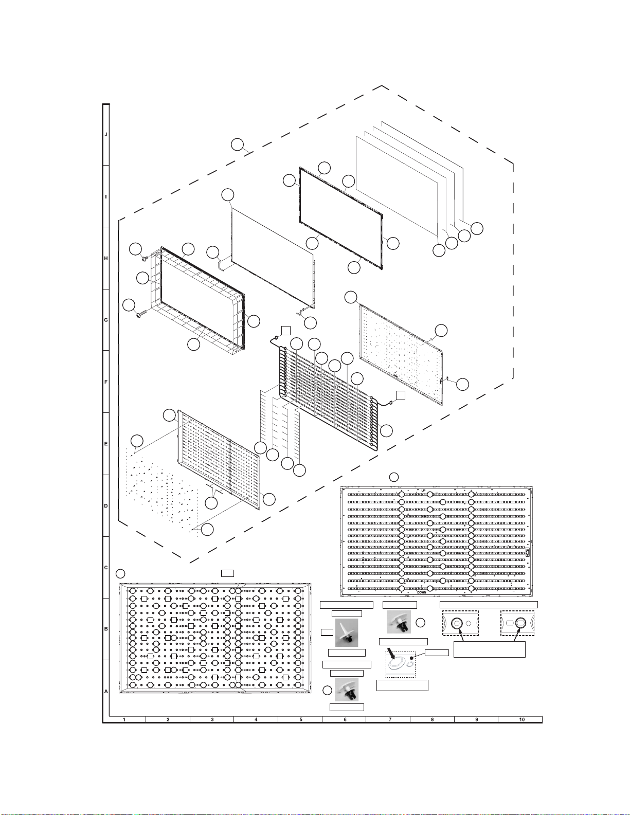
[4] LCD PANEL MODULE UNIT
1
16
12
4
2
13
LC-80LE632U
6
10
8
7
22
21
11
20
21
9
15
24
32
Insert PUSH RIVET (105 Locations) and
32
32
32
33
33
33
33 33
32
32
32 32
33 33
32
33
32
32
33
32
32
32
33
32
32
3333
32
32
32
33
32 32
32
32
33
32
33
32
32
32
32
32
32
32
32
32
32
32
32
32
32
32
32
19
5
3
14
L1
29
30
27
31
26
28
35
34
L2
25
32
32
32
32
36
23
33
Insert PUSH RIVET (36 Locations)
33
32
32
32
33
32
32
32
32
32
33
32
32
32
32
32
33
33
32
33
32
32
32
33
32
32
33
32
33
32
32
333333
32
33
32
32
32
32
32
32
32
32
33
32
32
33
32
33
32
32
32
33
32
33
32
323232
32
32
32
33
32
32
32
33
32
32
33
32
33
32
3232
32
32
32
32
32
32
32
32
32
3232
32
32
Insert SUPPORT PIN.
36 locations
33
SUPPORT PIN
Insert PUSH RIVET.
105 locations
32
PUSH RIVET
32
Insert PUSH RIVET (45 Locations)
32
32
32
32
32
32
32
32
32
32
32
32
32
32
32
PUSH RIVET
32
Insert PUSH RIVET.
Insert it well to the depths.
Not bein g f loat .
32
32
32
32
32
32
32
32
32
32
32
32
32
32
32
32
32
32
32
32
32
32
32
32
32
32
32
32
32
32
Fasten LED-PWBs with PUSH RIVETs x 45
In th e i nserti on place (45place s),
there is a circle marking
LED-PWB
bysilk-screen printing on LED-PWB.
5
Page 46
LC-80LE632U
NO. PARTS CODE
PRICE
RANK
NEW
MARK
PAR T
DELIVERY
[4] LCD PANEL MODULE UNIT
1 R1LK800D3GW10Z K 80" LCD Panel Module Unit (LK800D3GW10Z)
2 CANGK5031TP01 X Bezel Unit (Top)
3 CANGK5032TP01 X Bezel Unit (Bottom)
4 CANGK5033TP01 X Bezel Unit (Left)
5 CANGK5034TP01 X Bezel Unit (Right)
6 CHLDZ4922TP01 X P-Chassis Unit (Top/Left)
7 CHLDZ4928TP01 X P-Chassis Unit (Bottom/Right)
8 CHLDZ4923TP01 X P-Chassis Unit (Left/Left)
9 CHLDZ4929TP01 X P-Chassis Unit (Right/Right)
10 CHLDZ4924TP01 X P-Chassis Unit (Left)
11 CHLDZ4925TP01 X P-Chassis Unit (Right)
12 LX-EZA028WJF9 X Screw, x26
13 QCNWN2811TPZA X SG-FFC
14 QCNWN2811TPZB X SG-FFC
15 LX-BZ2564TPZZ X Screw, x32
16 KSETM1033TPZZ X Panel
19 CCHSM0360TP01 X BL Chassis Unit Ass'y
20 POFMA1311TPZZ X Lens Sheet
21 PSLDK3625TPZZ X Microlens Sheet
22 PSLDK3626TPZZ X Diffusion Plate
23 PREFL3374TPZZ X Reflection Sheet (Left)
24 PREFL3375TPZZ X Reflection Sheet (Right)
25 QCNWN2810TPZZ X LED PWB Connection Harness
26 RUNTK5069TPZZ X LED Unit, x8
27 RUNTK5070TPZZ X LED Unit, x7
28 RUNTK5071TPZZ X LED Unit, x8
29 RUNTK5072TPZZ X LED Unit, x7
30 RUNTK5073TPZZ X LED Unit, x8
31 RUNTK5074TPZZ X LED Unit, x7
32 LX-LZ0001TPZZ X Push Rivet, x150
33 LHLDZ4926TPZZ X Support Pin, x36
34 LHLDW0310TPZZ X Wire Holder
35 TLABN2229TPZZ X Bar code Label
36 PTPEH1708TPZZ X
Two side Tape, x2
DESCRIPTION
6
Page 47
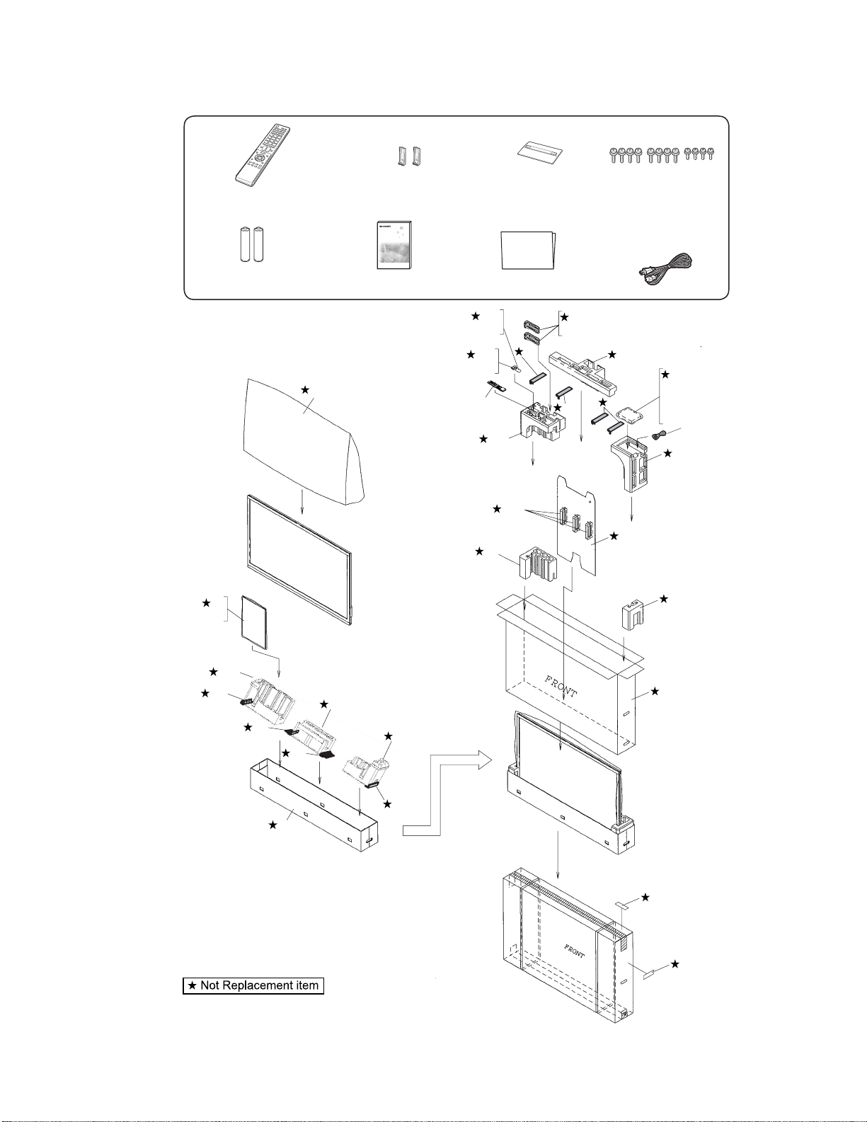
[5] SUPPLIED ACCESSORIES/PACKING PARTS
X1 X2 X3
X4
Remote control unit (x1)
Stand support Ass'y (x2) Stand Base Ass'y (x1) Stand Screw Ass'y (x1)
LC-80LE632U
X5 Enquete card
X6 Guarantee card
X10
X9
“AAA” size battery (x2)
S3
X2
S12
S6
S6
S6
X7 X8
Operation manual (x1) Connection guide (x1)
S2
X3
S5
X9
S10
S12
S12
X4
S11
S12
S13
S5
X1
S5
S4
S5
S11
S9
AC Cord
S1
X6
X7
X8
X5
X10
S11
S12
S8
S7
S6
S14
S14
7
Page 48

LC-80LE632U
NO. PARTS CODE
PRICE
RANK
NEW
MARK
[5] SUPPLIED ACCESSORIES/PACKING PARTS
X1 CANGKD276WJ04 N X Stand Support Ass'y, x2
X2 CDAI-A806WJ31 N X Stand Base Ass'y
X3 CSAKKA011WJ01 X Stand Screw Ass'y
X4 RRMCGA935WJSA X Remote Control
X5 TCADEA290WJZZ N X Enquet Card
X6 TGAN-B610WJZZ X Guarantee Card
X7 TINS-F316WJZZ N X Operation Manual
X8 TMAN-A043WJZZ X Conection Guide
X9 Not Available - - AAA size Battery
!
X10 QACCDA073WJPZ X AC Cord
S1 SSAKA0101GJZZ - - Polyethylene Bag (NOT REPLACEMENT ITEM)
S2 SSAKKA011WJZZ - N - Polyethylene Bag (NOT REPLACEMENT ITEM)
S3 SPAKPB792WJZZ - N - Wrapping Paper (NOT REPLACEMENT ITEM)
S4 SPAKPB793WJZZ - N - Wrapping Paper (NOT REPLACEMENT ITEM)
S5 SPAKAA694WJZZ - N - Packing Add. (NOT REPLACEMENT ITEM)
S6 SPAKAA695WJZZ - N - Packing Add. (NOT REPLACEMENT ITEM)
S7 SPAKCG509WJZZ - N - Packing Case (NOT REPLACEMENT ITEM)
S8 SPAKCG566WJZZ - N - Packing Case (NOT REPLACEMENT ITEM)
S9 SPAKFC163WJZZ - N - Packing Material (NOT REPLACEMENT ITEM)
S10 SPAKPB788WJZZ - N - Wrapping Paper (NOT REPLACEMENT ITEM)
S11 SPAKXD498WJZZ - N - Packing Add. (NOT REPLACEMENT ITEM)
S12 SPAKXD499WJZZ - N - Packing Add. (NOT REPLACEMENT ITEM)
S13 SPAKXD500WJZZ - N - Packing Add. (NOT REPLACEMENT ITEM)
S14 TLABKA009WJZZ - - Case NO. Label (NOT REPLACEMENT ITEM)
[6] SERVICE JIGS (USE FOR SERVICING)
N QCNW-C222WJQZ AW J Connecting Cord L=1000mm 80pins, LCD Control Unit to LCD Panel Unit, x2
N QCNW-F676WJQZ BH J Connecting Cord L=1000mm 41pins, Main to LCD Control Unit (LW)
N QCNW-L795WJQZ BC J Connecting Cord L=1000mm 24pins, Main to POWER Unit (PD)
N QCNW-G405WJQZ AP J Connecting Cord L=1000mm 4pins, Power to LCD Control Unit (PL)
PAR T
DELIVERY
DESCRIPTION
8
Page 49

LC-80LE632U
Page 50

LC-80LE632U
COPYRIGHT © 2011 BY SHARP CORPORATION
ALL RIGHTS RESERVED.
No Part of this publication may be reproduced,
stored in a retrieval system, or transmitted in
any from or by any means, electronic, mechanical,
photocopying, recording, or otherwise, without
prior written permission of the publisher.
Sep. 2011
SH. DS
SHARP CORPORATION
AV Systems Group
CS Promotion Center
Yaita,Tochigi 329-2193, Japan
 Loading...