

Page 1
32″&42″&50″LCD TV Best Buy LC-32LB261U- LC-42LB261U- LC-50LB261U
Service
Service
Service
TABLE OF CONTENTS
Description Page Description Page
Table Of Contents.......……..............................………......1
Important Safety Notice.......................................……......2
Revision List…………………………………………………3
1. General Specification..............................………...........4
2. Operating Instructions…………………….……...….......5
3. Input/Output Specification…………....................…....6
4. Mechanical Instructions…………………….................9
5. Repair Flow Chart.……………………….…….…….....18
6. PCB Layout.………………..……………….....….........25
6.1 Main Board…………..……………...………...............25
6.2 Power Board……………..………….……….….......27
6.3 Key Board………………………..………………......33
6.4 IR Board…………………………..……………........33
SAFETY NOTICE
ANY PERSON ATTEMPTING TO SERVICE THIS CHASSIS MUST FAMILIARIZE HIMSELF WITH THE CHASSIS
7. Adjustment..............................................................34
7.1 ADC and W/B Adjustment………………..…….34
7.2 F/W upgrade……………………..……………........35
7.3 DDC upgrade…………………..……………........36
8. Block Diagram.…….................................................37
9. Schematic……………...…………..……..…………...39
9.1 Main Board…………………………………...….......39
9.2 Power Board…………….…………...…………......53
9.3 Key Board……………….……………………….......63
9.4 IR Board………………………………..….…….......64
10. LOCATION Waveform and Voltage…………..….65
11. Exploded View……………………………….….…...68
12. BOM List……………….……………………………77
AND BE AWARE OF THE NECESSARY SAFETY PRECAUTIONS TO BE USED WHEN SERVICING
ELECTRONIC EQUIPMENT CONTAINING HIGH VOLTAGES.
CAUTION: USE A SEPARATE ISOLATION TRANSFOMER FOR THIS UNIT WHEN SERVICING
1
Page 2

32″&42″&50″LCD TV Best Buy LC-32LB261U- LC-42LB261U- LC-50LB261U
Important Safety Notice
Proper service and repair is important to the safe, reliable operation of all AOC Company Equipment. The service
procedures recommended by AOC and described in this service manual are effective methods of performing service
operations. Some of these service operations require the use of tools specially designed for the purpose. The
special tools should be used when and as recommended.
It is important to note that this manual contains various CAUTIONS and NOTICES which should be carefully read in
order to minimize the risk of personal injury to service personnel. The possibility exists that improper service
methods may damage the equipment. It is also important to understand that these CAUTIONS and NOTICES ARE
NOT EXHAUSTIVE. AOC could not possibly know, evaluate and advise the service trade of all conceivable ways in
which service might be done or of the possible hazardous consequences of each way. Consequently, AOC has not
undertaken any such broad evaluation. Accordingly, a servicer who uses a service procedure or tool which is not
recommended by AOC must first satisfy himself thoroughly that neither his safety nor the safe operation of the
equipment will be jeopardized by the service method selected.
Hereafter throughout this manual, AOC Company will be referred to as AOC.
WARNING
Use of substitute replacement parts, which do not have the same, specified safety characteristics, might create
shock, fire, or other hazards.
Under no circumstances should the original design be modified or altered without written permission from AOC.
AOC assumes no liability, express or implied, arising out of any unauthorized modification of design.
Servicer assumes all liability.
FOR PRODUCTS CONTAINING LASER:
DANGER-Invisible laser radiations when open AVOID DIRECT EXPOSURE TO BEAM.
CAUTION-Use of controls or adjustments or performance of procedures other than those specified herein may
result in hazardous radiation exposure.
CAUTION -The use of optical instruments with this product will increase eye hazard.
TO ENSURE THE CONTINUED RELIABILITY OF THIS PRODUCT, USE ONLY ORIGINAL MANUFACTURER'S
REPLACEMENT PARTS, WHICH ARE LISTED WITH THEIR PART NUMBERS IN THE PARTS LIST SECTION OF
THIS SERVICE MANUAL.
Take care during handling the LCD module with backlight unit
-Must mount the module using mounting holes arranged in four corners.
-Do not press on the panel, edge of the frame strongly or electric shock as this will result in damage to the screen.
-Do not scratch or press on the panel with any sharp objects, such as pencil or pen as this may result in damage to
the panel.
-Protect the module from the ESD as it may damage the electronic circuit (C-MOS).
-Make certain that treatment person’s body is grounded through wristband.
-Do not leave the module in high temperature and in areas of high humidity for a long time.
-Avoid contact with water as it may a short circuit within the module.
-If the surface of panel becomes dirty, please wipe it off with a soft material. (Cleaning with a dirty or rough cloth may
damage the panel.)
2
Page 3

32″&42″&50″LCD TV Best Buy LC-32LB261U- LC-42LB261U- LC-50LB261U
Revision List
Version Release Date Revision Instructions Customer Model TPV Model
LC-32LB261U E32E41NKFMBSNNX
A00 May.30.2014 Initial Release
A01 Jun.13.2014 Add New Model LC-32LB261U E32E51NKFMBSNNX
A02 Jul. 22.2014 Add New Model
A03 Oct. 30.2014 Add New Model
LC-42LB261U E42E41NKFMBSNNX
LC-50LB261U E50E41NKFMBSNNX
LC-32LB261U E32E41NKFMBPNNX
LC-42LB261U E42E41NKFMBPNNX
LC-50LB261U E50E41NKFMBPNNX
E32E41NKFMBRNNX
LC-32LB261U
E32E51NKFMBRNNX
LC-42LB261U E42E41NKFMBRNNX
LC-50LB261U E50E41NKFMBRNNX
3
Page 4

32″&42″&50″LCD TV Best Buy LC-32LB261U- LC-42LB261U- LC-50LB261U
1. General Specification
Please refer to user manual.
4
Page 5

32″&42″&50″LCD TV Best Buy LC-32LB261U- LC-42LB261U- LC-50LB261U
2. Operating Instructions
Please refer to user manual.
5
Page 6
32″&42″&50″LCD TV Best Buy LC-32LB261U- LC-42LB261U- LC-50LB261U
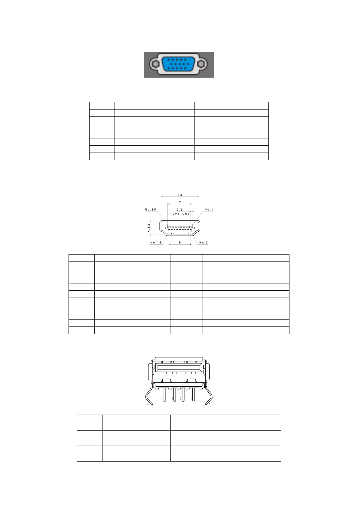
3. Input/output Specification
3.1 RGB Signal Input
15 - Pin Color Display Signal Cable
1 Red Video 9 VGA 5V
2 Green Video 10 Sync Ground
3 Blue Video 11 Uart RX
4 Uart TX 12 Serial Data for DDC
5 Ground 13 H-Sync.
6 Red Ground 14 V-Sync.
7 Green Ground 15 Serial Clock for DDC
8 Blue Ground
3.2 HDMI Digital connector pin assignments
3.3 USB
PIN Signal Assignment PIN Signal Assignment
1 TMDS Data2+ 2 TMDS Data2 Shield
3 TMDS Data2- 4 TMDS Data1+
5 TMDS Data1 Shield 6 TMDS Data17 TMDS Data0+ 8 TMDS Data0 Shield
9 TMDS Data0- 10 TMDS Clock+
11 TMDS Clock Shield 12 TMDS Clock13 CEC 14 NC
15 SCL 16 SDA
17 DDC/CEC Ground 18 +5V Power
19 Hot Plug Detect
PIN Signal Assignment PIN Signal Assignment
1 VCC 2 Data-
3 Data+ 4 GND
6
Page 7
32″&42″&50″LCD TV Best Buy LC-32LB261U- LC-42LB261U- LC-50LB261U
3.4 AV Signal Performance
3.4.1 Video / Component Video Input
All tests must be performed under “video standard testing conditions” unless otherwise specified
3.4.2 AV (Composite Video Input)
Amplitude 1.0 V (p-p), negative sync.
Impedance 75 ohm terminated
3.4.3 Component (Y, Pb/Cb, Pr/Cr Input)
Component
Y signal amplitude 1.0Vpp (including sync)
Cr, (R-Y) / Cb, (B-Y)
Y = 0.299R + 0.587G + 0.114B
Video
System NTSC
System 480i, 480P, 720P, 1080i, 1080P
±0.35Vpp, 75 ohm
Signal amplitude
Impedance
(R-Y) = 0.701R + 0.587G + 0.114B
(B-Y) = 0.299R + 0.587G + 0.886B
75 ohm terminated
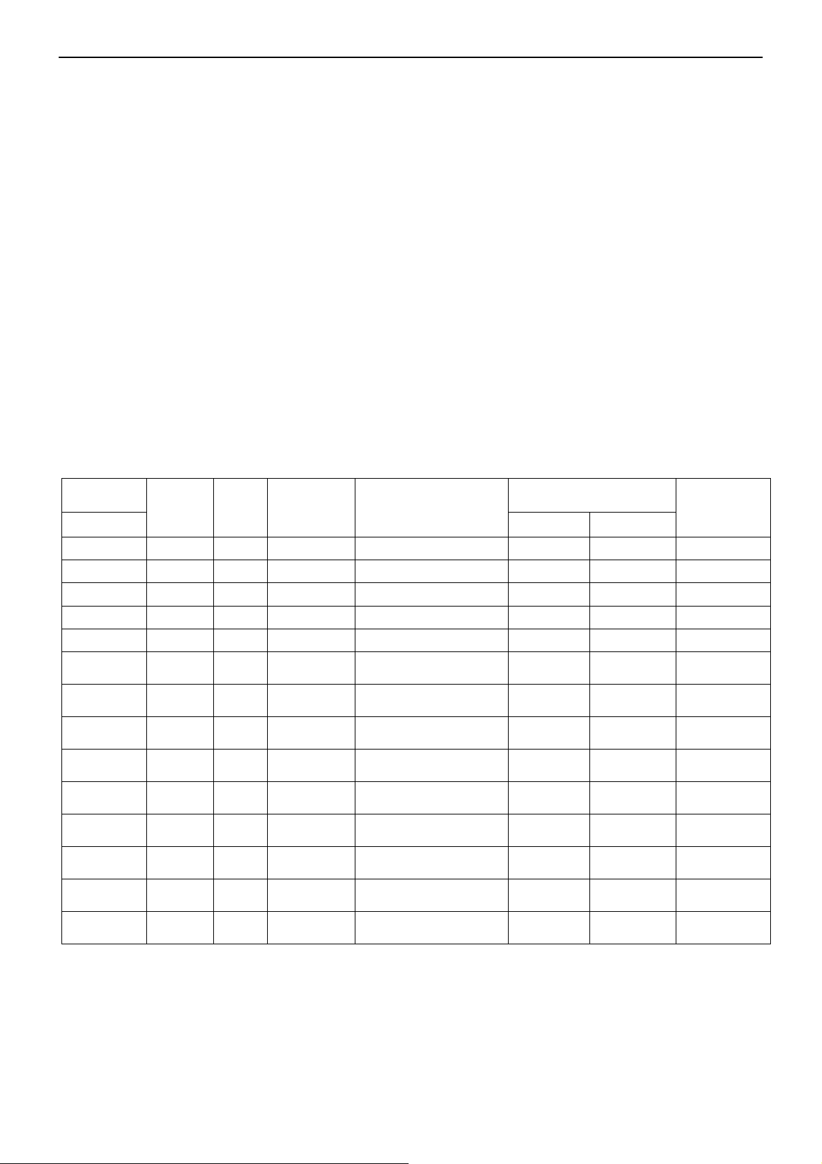
3.5 Compatible Mode Table
Analog RGB Input Signal Timing
Supported
Resolution
H×V
640×480
720×400
800×600
800×600
1024×768
1280×768
1280×720
1280×800
1280×800
1280×960
1280×1024
1440×900
1680×1050
1920×1080
H(KHZ) V(HZ) Standard EDID Assignment
31.5 60 VESA DMT
31.5 70 VESA DMT
37.9 60 VESA DMT
35.1 56 VESA
48.4 60 VESA DMT
47.4 60 VESA DMT
45 60 VESA DMT
49.7 60 VESA DMT
62.8 75 VESA DMT
60 60 VESA DMT
64 60 VESA DMT
55.9 60 VESA DMT
65.3 60 VESA DMT
67.5 60 CEA-861
Established Timings
Established Timings
Established Timings
Established Timings
Established Timings
Detailed Timing
Description 2
Standard Timing
Identification
Standard Timing
Identification
Standard Timing
Identification
Standard Timing
Identification
Standard Timing
Identification
Standard Timing
Identification
Standard Timing
Identification
Detailed Timing
Description 1
Panel Type
1366X768 1920X1080
YES YES
YES
YES
YES
YES
YES
YES
YES
YES
YES NOTE3
YES
YES 16:9
YES
YES 16:10
YES
YES
YES
YES 4:3
YES
YES
YES 5:4
YES
YES 16:10
NOTE1
YES
YES NOTE3
NO
NOTE2
16:10
Mandatory
16:10
Mandatory
7
Page 8
32″&42″&50″LCD TV Best Buy LC-32LB261U- LC-42LB261U- LC-50LB261U
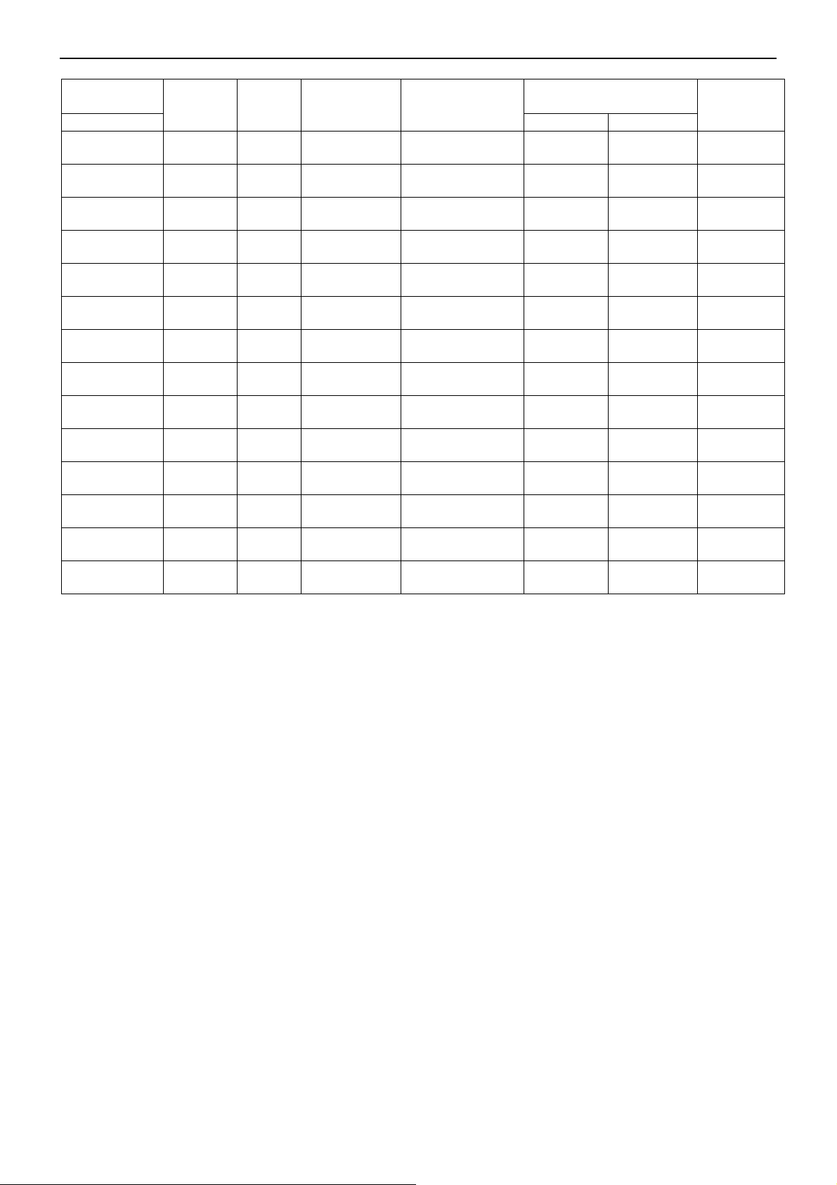
HDMI Input Signal Timing:
Supported
Resolution
H×V
640×480
720×400
800×600
800×600
1024×768
1280×768
1280×720
1280×800
1280×800
1280×960
1280×1024
1440×900
1680×1050
1920×1080
H(KHZ) V(HZ) Standard
31.5 60 VESA DMT
31.5 70 VESA DMT
37.9 60 VESA DMT
35.1 56 VESA
48.4 60 VESA DMT
47.4 60 VESA DMT
45 60 VESA DMT
49.7 60 VESA DMT
62.8 75 VESA DMT
60 60 VESA DMT
64 60 VESA DMT
55.9 60 VESA DMT
65.3 60 VESA DMT
67.5 60 CEA-861
EDID
Assignment
Established
Timings
Established
Timings
Established
Timings
Established
Timings
Established
Timings
Detailed Timing
Description 2
Standard Timing
Identification
Standard Timing
Identification
Standard Timing
Identification
Standard Timing
Identification
Standard Timing
Identification
Standard Timing
Identification
Standard Timing
Identification
Detailed Timing
Description 1
Panel Type
1366X768 1920X1080
YES
YES
YES
YES
YES
YES
YES
YES
YES
YES
YES
YES NOTE3
YES
YES 16:9
YES 16:10
YES
YES
YES
YES
YES 4:3
YES 5:4
YES
YES
YES 16:10
NOTE1
YES
YES
YES NOTE3
NOTE2
16:10
Mandatory
16:10
Mandatory
8
Page 9
32″&42″&50″LCD TV Best Buy LC-32LB261U- LC-42LB261U- LC-50LB261U
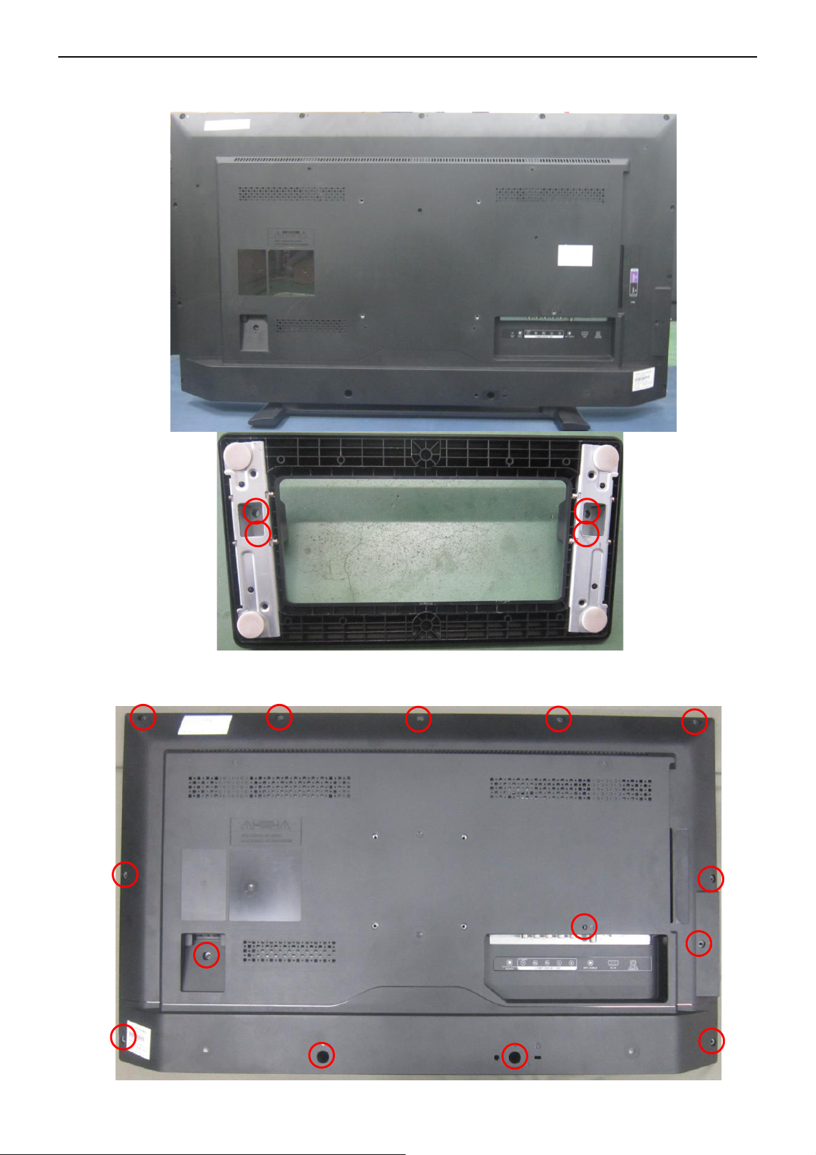
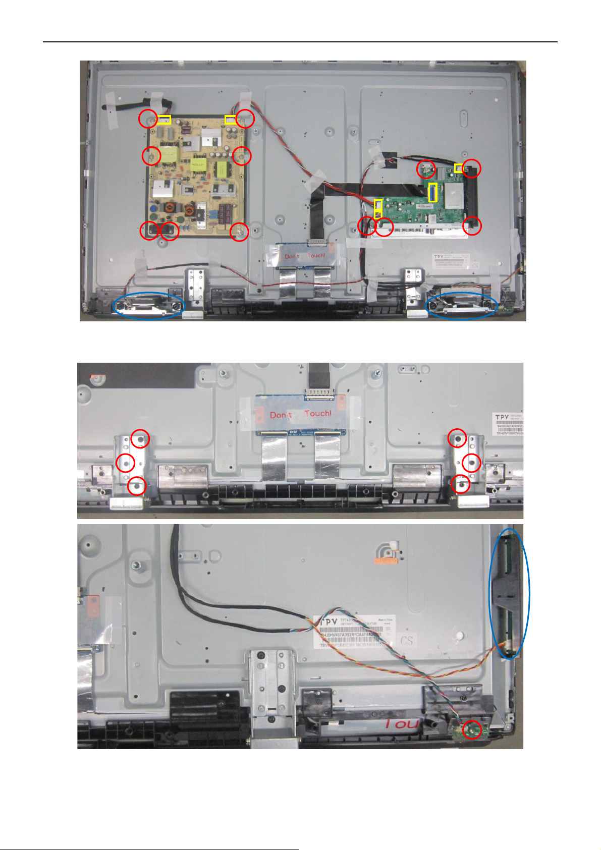
4. Mechanical Instructions
LC-32LB261U
1. Remove the screw to remove the BASE.
2. Remove the screw to remove the REAR COVER.
9
Page 10
32″&42″&50″LCD TV Best Buy LC-32LB261U- LC-42LB261U- LC-50LB261U
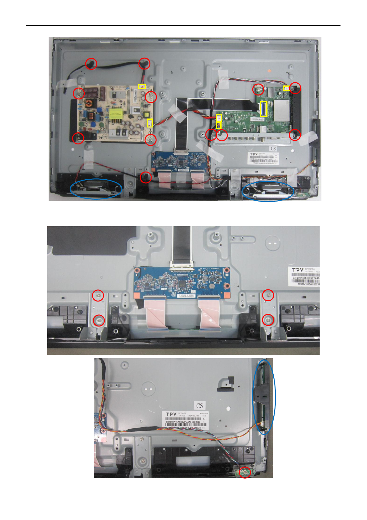
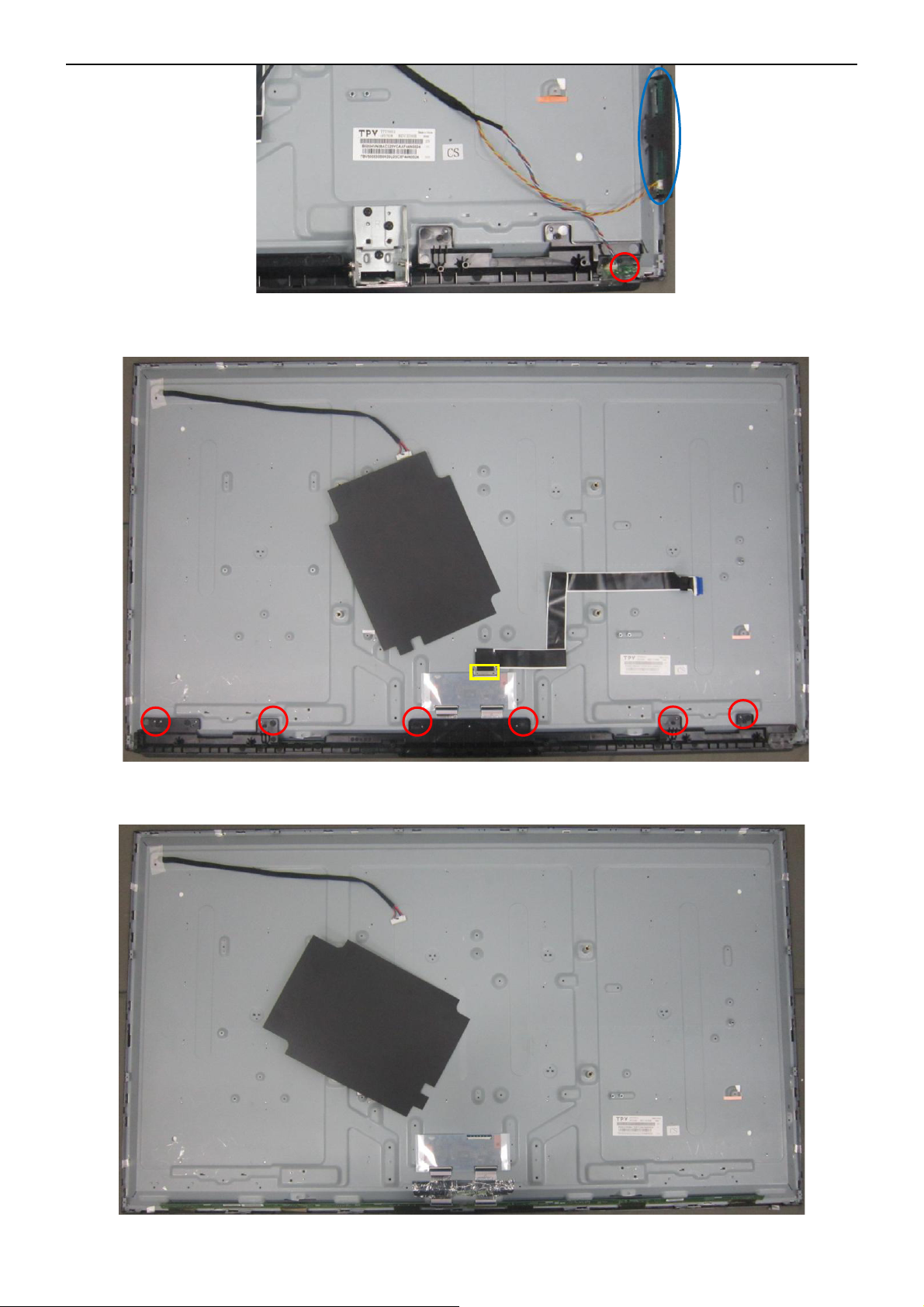
3. Remove the connectors and screws to remove MAIN BOARD, POWER BOARD, SPEAKERS, BKT_IO.
4. Remove the screw to remove BKT_STAND, KEYPAD, IR BOARD.
10
Page 11
32″&42″&50″LCD TV Best Buy LC-32LB261U- LC-42LB261U- LC-50LB261U
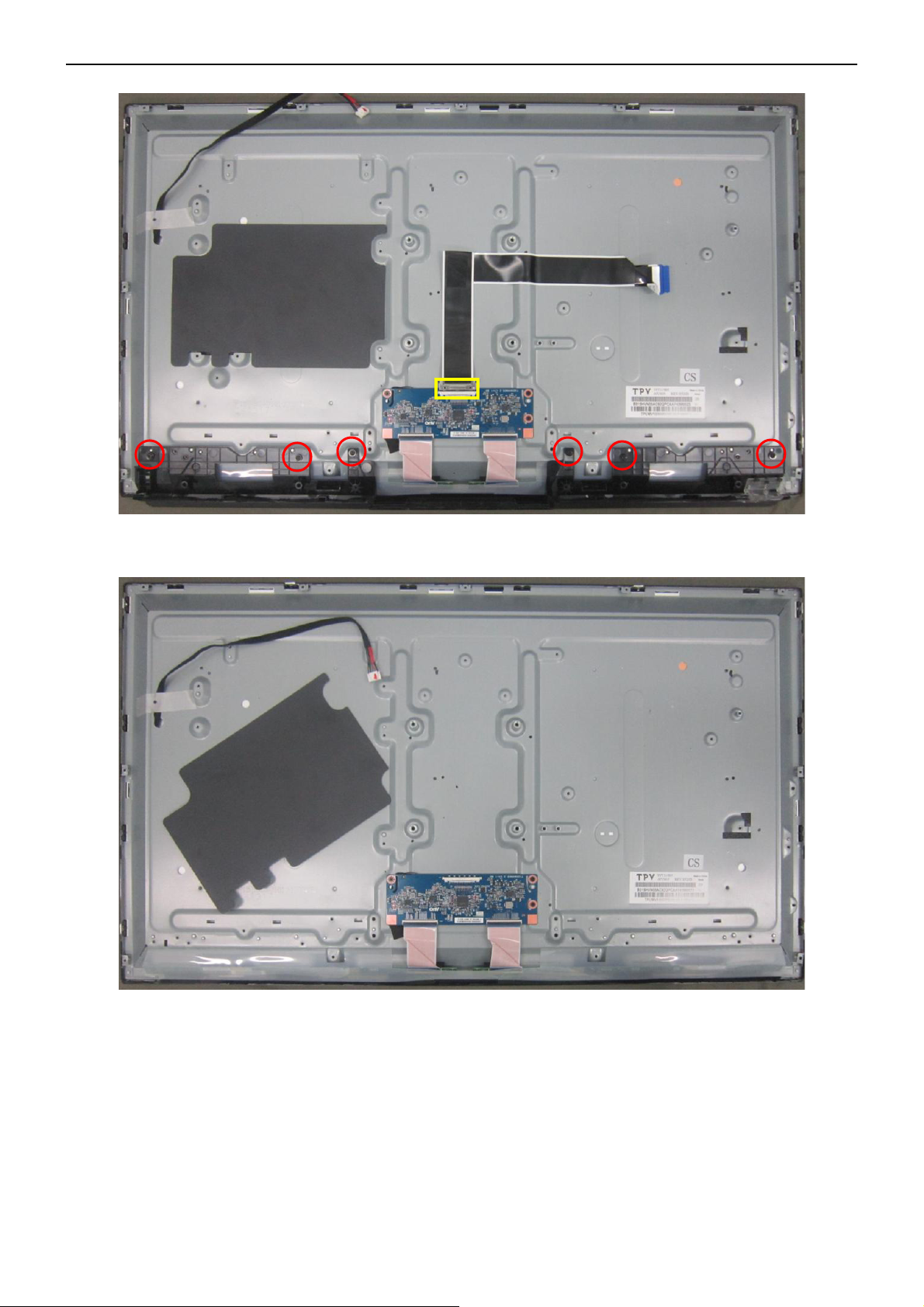
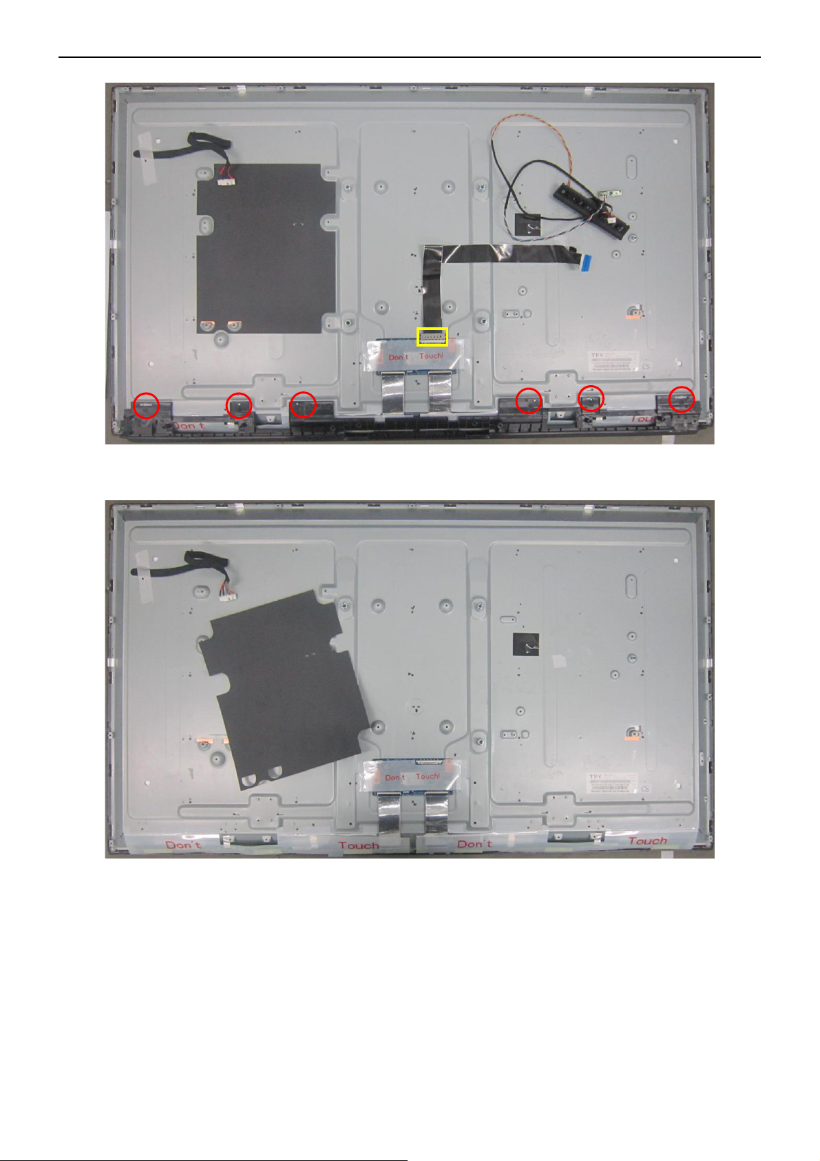
5. Remove the screw to remove FFC CABLE, DECO.
6. PANEL.
11
Page 12
32″&42″&50″LCD TV Best Buy LC-32LB261U- LC-42LB261U- LC-50LB261U
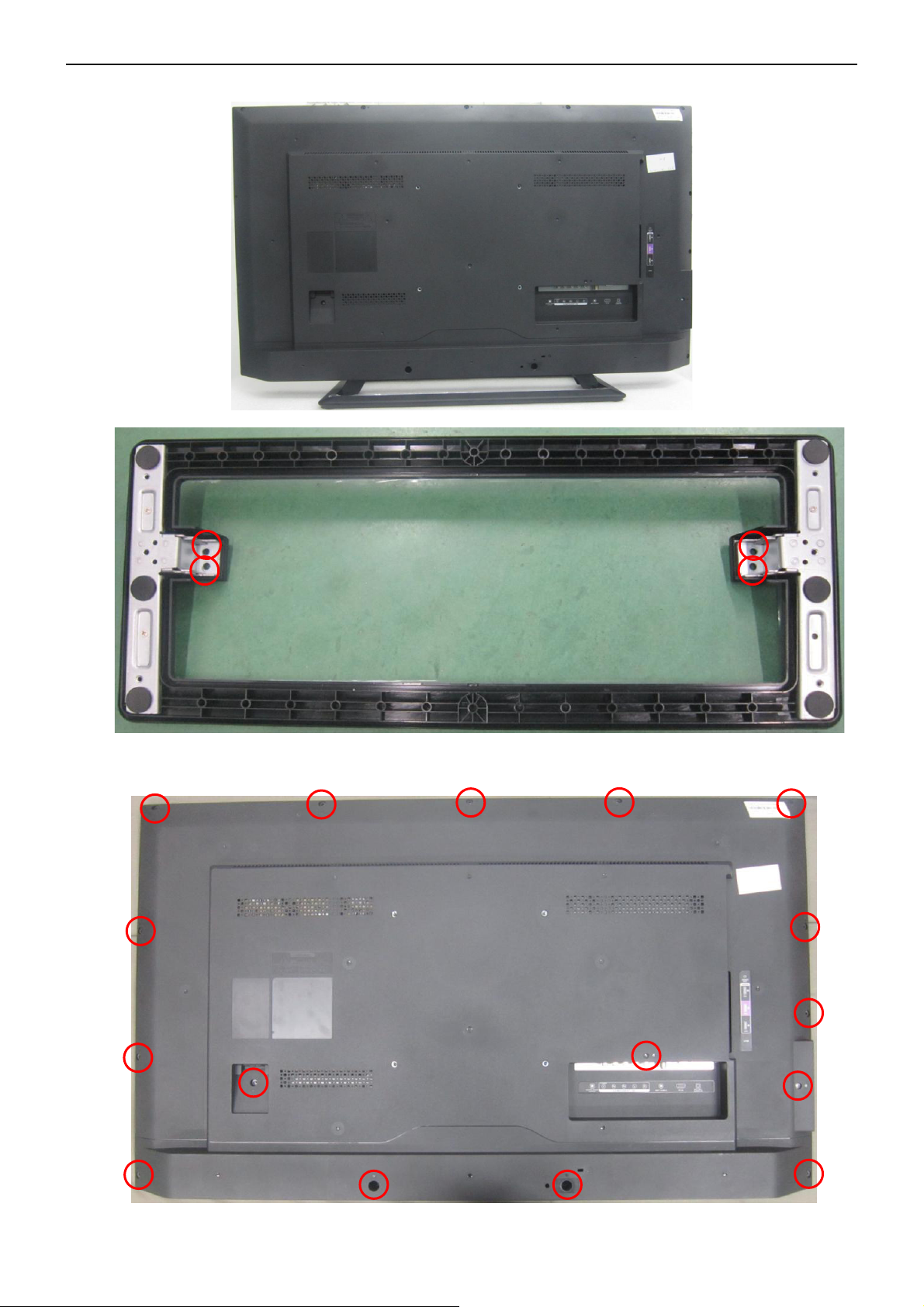
LC-42LB261U
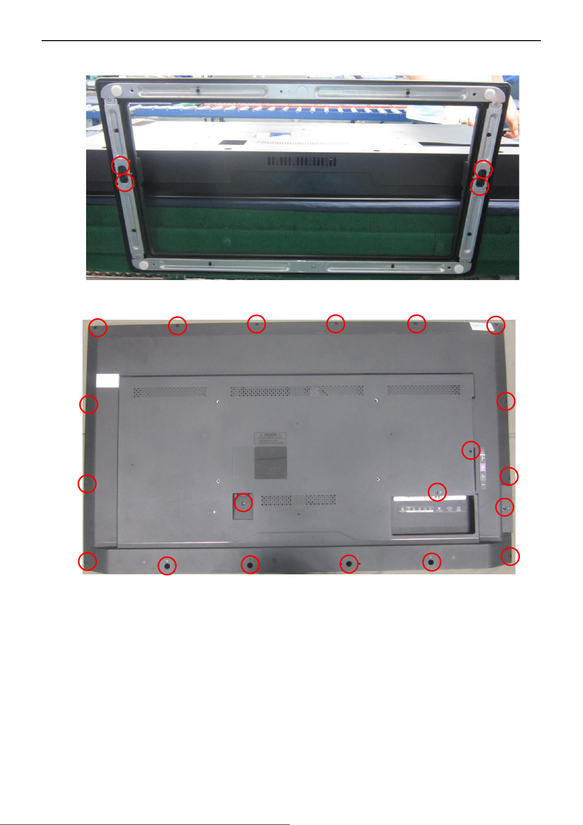
1. Remove the screw to remove the BASE.
2. Remove the screw to remove the REAR COVER.
12
Page 13
32″&42″&50″LCD TV Best Buy LC-32LB261U- LC-42LB261U- LC-50LB261U
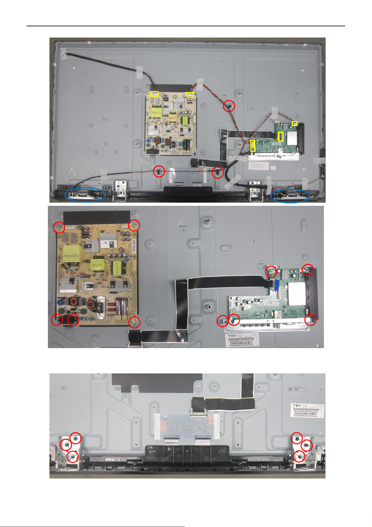
3. Remove the connectors and screws to remove MAIN BOARD, POWER BOARD, SPEAKERS, BKT_IO.
4. Remove the screw to remove BKT_STAND, KEYPAD, IR BOARD.
13
Page 14
32″&42″&50″LCD TV Best Buy LC-32LB261U- LC-42LB261U- LC-50LB261U
5. Remove the screw to remove FFC CABLE, DECO.
6. PANEL.
14
Page 15
32″&42″&50″LCD TV Best Buy LC-32LB261U- LC-42LB261U- LC-50LB261U
LC-50LB261U
1. Remove the screw to remove the BASE.
2. Remove the screw to remove the REAR COVER.
15
Page 16
32″&42″&50″LCD TV Best Buy LC-32LB261U- LC-42LB261U- LC-50LB261U
3. Remove the connectors and screws to remove MAIN BOARD, POWER BOARD, SPEAKERS, BKT_IO.
4. Remove the screw to remove BKT_STAND, KEYPAD, IR BOARD.
16
Page 17
32″&42″&50″LCD TV Best Buy LC-32LB261U- LC-42LB261U- LC-50LB261U
5. Remove the screw to remove FFC CABLE, DECO.
6. PANEL.
17
Page 18

32″&42″&50″LCD TV Best Buy LC-32LB261U- LC-42LB261U- LC-50LB261U
p
p
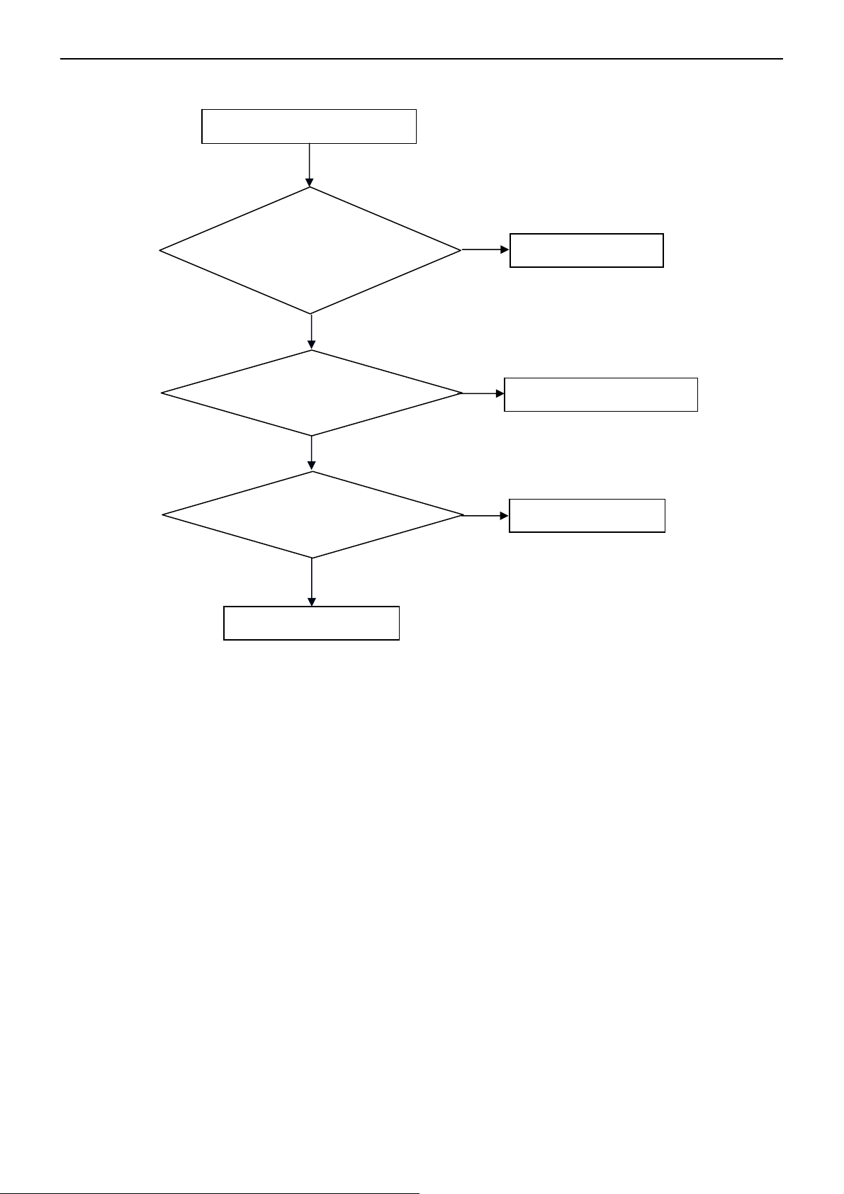
5. Repair Flow Chart
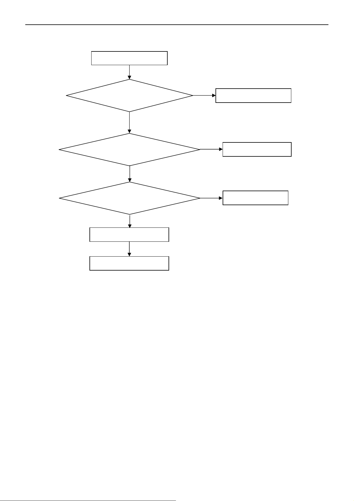
1. No power
No power (LED “Off”)
Check the AC input and
the
ower is “ON”?
Yes
Power board
out
ut=12V,5V?
Yes
Check the IR board and LED
Replace the IR board
No
Replace the main board
No
Power “On”
No
Replace the power board
18
Page 19
32″&42″&50″LCD TV Best Buy LC-32LB261U- LC-42LB261U- LC-50LB261U
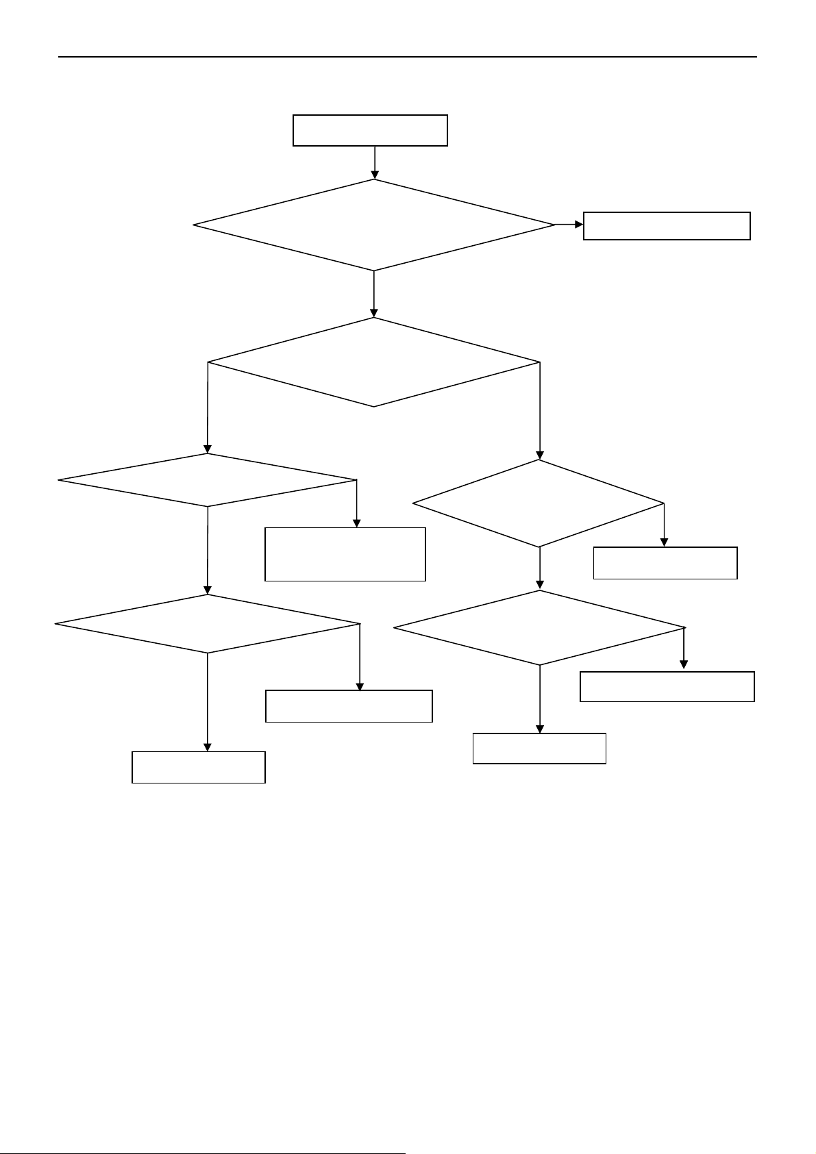
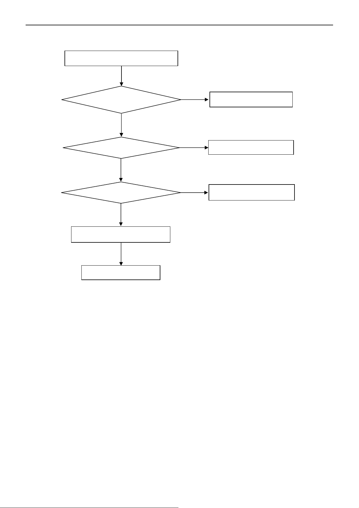
2. Can’t start
Can’t start(LED red)
No
Power board output=12,19.5V?
Yes
Check the power key is under control?
No
Check the IR receiver is normal?
Yes
Yes
Replace the power board
Replace the key board
Replace the IR board
No
Replace the main board
No
Replace the Power board
19
Page 20

32″&42″&50″LCD TV Best Buy LC-32LB261U- LC-42LB261U- LC-50LB261U
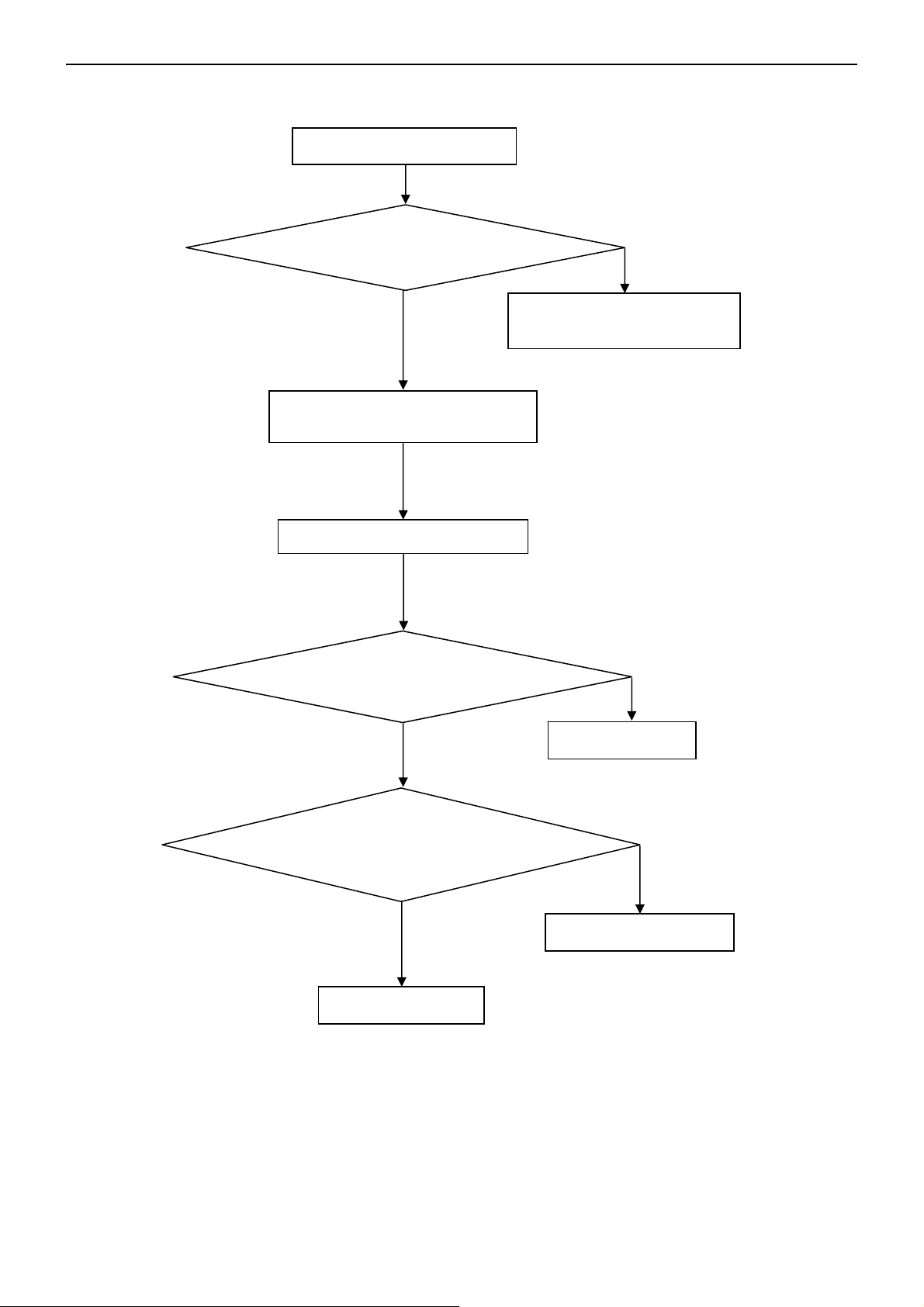
3. Abnormal display
Abnormal Display
No
Check the source
Yes
Enter factory mode to do
“EEPROM initial”&“Reset”
No
Reset the source
Check the main board
Yes
Check the LVDS cable
Yes
Check the panel
No
Replace the panel
No
Replace the main board
No
Replace the LVDS cable
20
Page 21
32″&42″&50″LCD TV Best Buy LC-32LB261U- LC-42LB261U- LC-50LB261U
4. No display
No display (LED blue)
Check TV is under control and power
on/off by remote control and power key?
Yes
Check the LVDS cable
Yes
Yes
Check the backlight is
“On”?
No
Reinsert or replace the
LVDS cable
No
No
Check the B/L
signal is available?
Yes
Replace the main board
No
Replace main board
Panel Vcc = 12V?
Yes
Replace the Panel
No
Replace the main board
Power board output=12V,19.5V?
No
Yes
Replace the Panel
Replace the power board
21
Page 22
32″&42″&50″LCD TV Best Buy LC-32LB261U- LC-42LB261U- LC-50LB261U
5. Sound problem
No sound or sound abnormal
Check the audio source connection
and the TV system are correct?
Yes
Check the TV is muted, adjust the
volume or enter the menu to reset?
No
No
Reinsert the audio cable or
change the TV system
Enter factory mode to do “Reset”
No
Check the cable between the
speakers and main board is OK?
Yes
Check the speaker resistance value is in spec
(Remark: The value is marked on the speaker)?
Yes
Replace the cable
Replace the main board
No
No
Replace the speaker
22
Page 23
32″&42″&50″LCD TV Best Buy LC-32LB261U- LC-42LB261U- LC-50LB261U
6. Remote control malfunction
Remote Control malfunction
Check the remote control battery is
not properly placed or no power?
No
Use the other remote controls
No
Whether the IR board is
abnormal?
No
Replace the main board
Yes
Replace the battery
Yes
Replace the remote control
Yes
Replace the IR board
23
Page 24
32″&42″&50″LCD TV Best Buy LC-32LB261U- LC-42LB261U- LC-50LB261U
7. OSD is unstable or can’t work normally
OSD is unstable or can’t work normally
Key board connected properly?
Yes
Buttons are OK?
Yes
Key board is OK?
Yes
Enter factory mode to do “Reset”
No
No
No
No
Reconnect the key board
Replace the button function
Replace the key board
Replace the main board
24
Page 25
32″&42″&50″LCD TV Best Buy LC-32LB261U- LC-42LB261U- LC-50LB261U
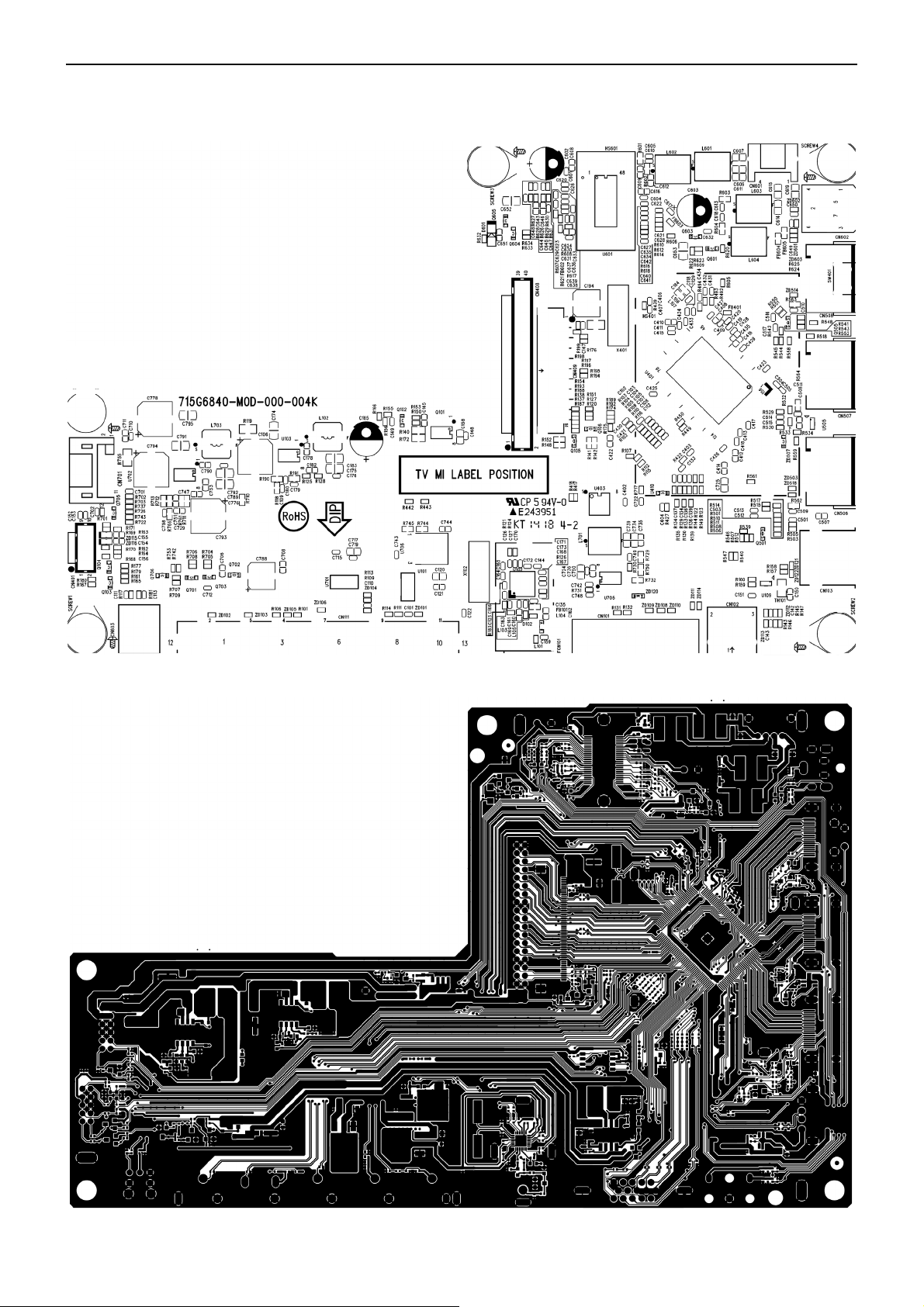
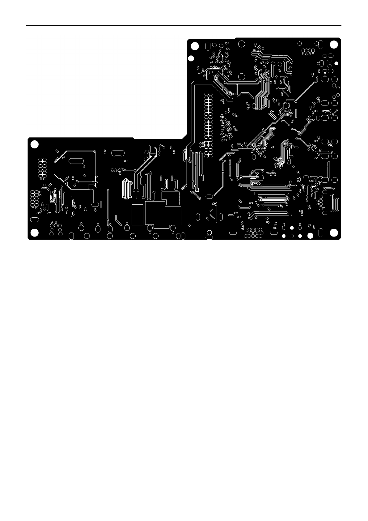
6. PCB Layout
6.1 Main Board
715G6840M0D000004
25
Page 26
32″&42″&50″LCD TV Best Buy LC-32LB261U- LC-42LB261U- LC-50LB261U
26
Page 27
32″&42″&50″LCD TV Best Buy LC-32LB261U- LC-42LB261U- LC-50LB261U
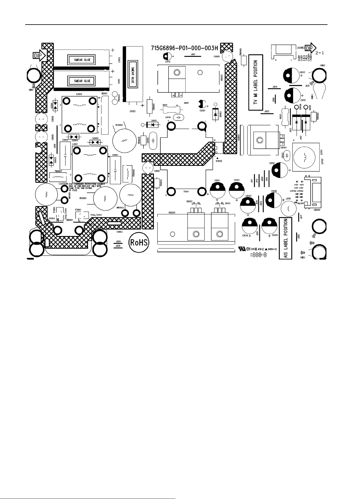
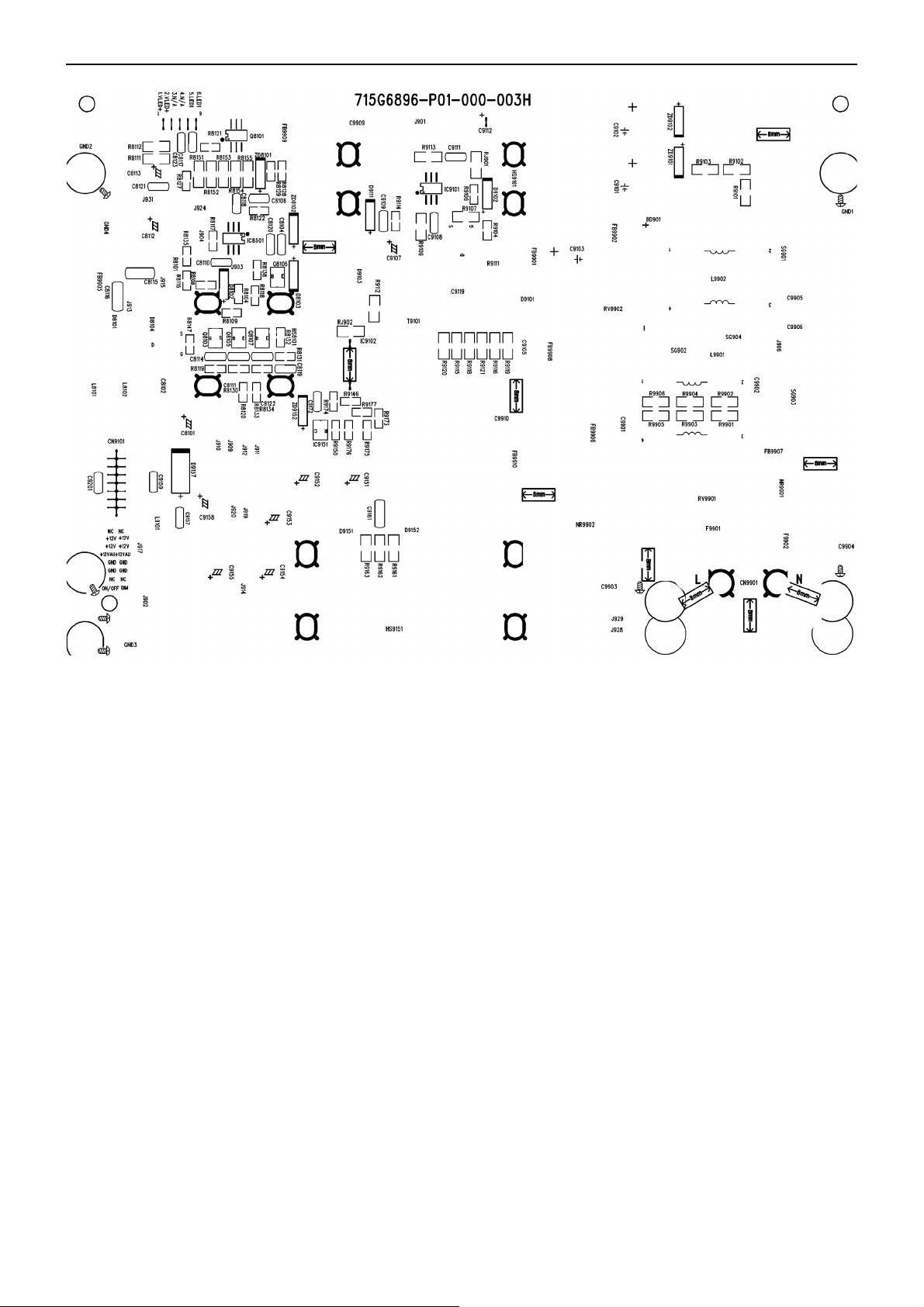
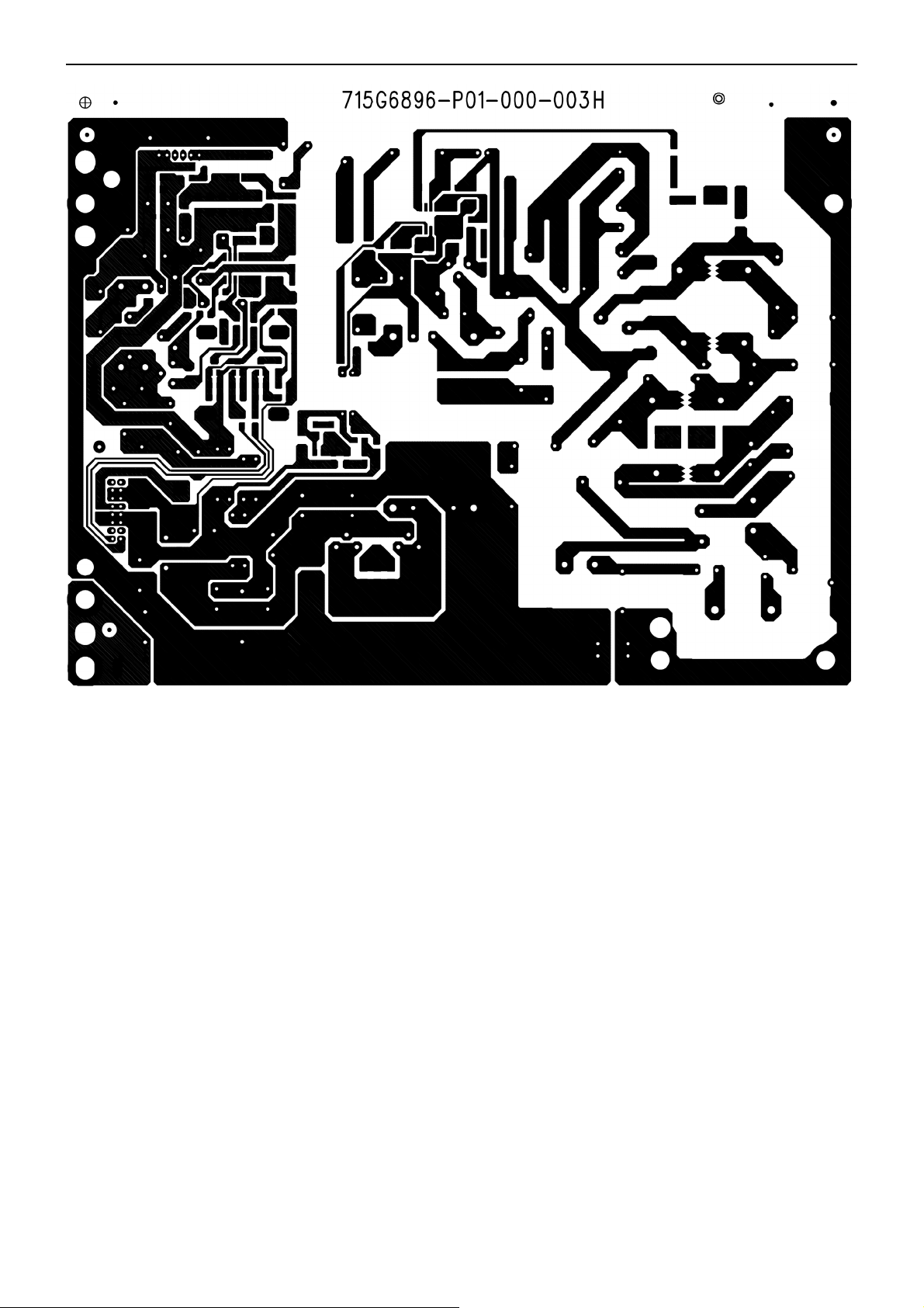
6.2 Power Board
715G6896P01000003H (32”)
27
Page 28
32″&42″&50″LCD TV Best Buy LC-32LB261U- LC-42LB261U- LC-50LB261U
28
Page 29
32″&42″&50″LCD TV Best Buy LC-32LB261U- LC-42LB261U- LC-50LB261U
29
Page 30
32″&42″&50″LCD TV Best Buy LC-32LB261U- LC-42LB261U- LC-50LB261U
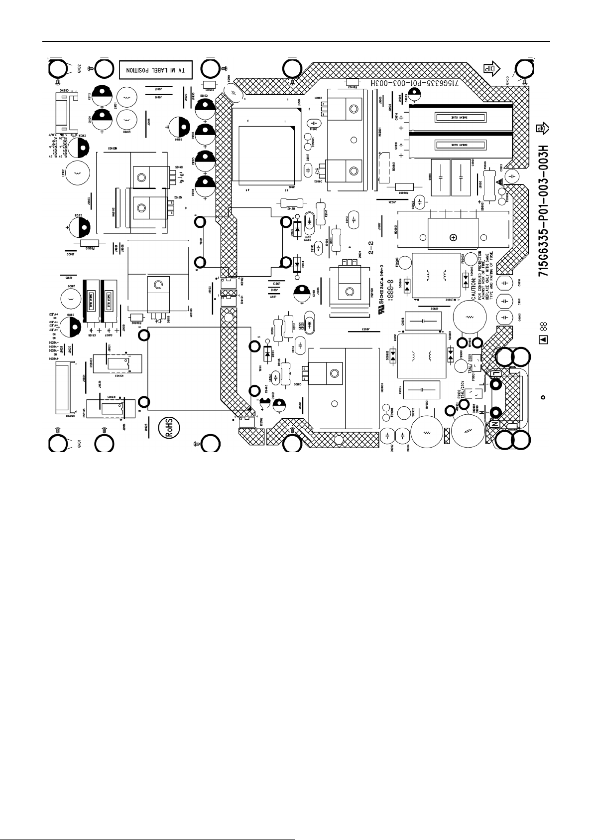
715G6335P01003003 (42” & 50”)
30
Page 31

32″&42″&50″LCD TV Best Buy LC-32LB261U- LC-42LB261U- LC-50LB261U
31
Page 32

32″&42″&50″LCD TV Best Buy LC-32LB261U- LC-42LB261U- LC-50LB261U
32
Page 33

32″&42″&50″LCD TV Best Buy LC-32LB261U- LC-42LB261U- LC-50LB261U
6.3 Key Board
715G6715K0A002004I
6.4 IR Board
715G5704R01000004X
33
Page 34

32″&42″&50″LCD TV Best Buy LC-32LB261U- LC-42LB261U- LC-50LB261U
7. Adjustment
7.1 ADC and W/B adjustment
ADC adjust
ADC don’t need to adjust.
White Balance adjust
This machine can't adjust the white balance manually.
34
Page 35

32″&42″&50″LCD TV Best Buy LC-32LB261U- LC-42LB261U- LC-50LB261U
7.2 F/W upgrade with USB SOP
(Take LC-32LB261U for example)
Step 1: Ready for F/W Upgrade
1.1 Prepare a USB memory (The file system of USB memory must be FAT16 or FAT 32).
1.2 Copy the software from your computer to USB memory root path, and remove it from computer’s USB port!
Step 2: F/W Upgrade
2.1 AC ON TV.
2.2 Press the power key on the Remote Control or the right side of TV to turn on TV.
2.3 Plug the USB memory to the USB port of TV.
2.4 When TV detect the USB memory and display below Upgrade info. select “Yes” option to upgrade F/W.
2.5 TV will upgrade automatically.
Notes: When Upgrade in the process, please don’t Power-Off!
35
Page 36

32″&42″&50″LCD TV Best Buy LC-32LB261U- LC-42LB261U- LC-50LB261U
2.6 When upgrade 100% and prompt for Upgrade Success info , remove the USB memory and AC off.
Step 3: Check the F/W version.
3.1 Press “MENU+1+9 +9 +9+enter” key to enter the factory mode.
3.2 Check the F/W version on the factory mode and then choose “Reset To Default” to reset TV.
7.3 DDC upgrade
As the DDC data was included in the software, this model does not need a separate DDC Upgrade.
36
Page 37

32″&42″&50″LCD TV Best Buy LC-32LB261U- LC-42LB261U- LC-50LB261U
8. Block Diagram
37
Page 38

32″&42″&50″LCD TV Best Buy LC-32LB261U- LC-42LB261U- LC-50LB261U
P12V_AUD
U601 TAS5729
+12V_AUD
For Audio Amplifier
P12V
Q104 AO4449-7A
U70 7
TPS54339DDAR
+5V SB
Q702 AO4449-7A
PANEL LVDS Power
U701 AP1117E33L-13-77
3V3_STB
VCCK
U705 AT1529 For M SD82 2 0L B- S9
U401 MSD8220LB
U405 G690H293T73
U403 W25Q32FVSSIG
U401 MSD8220LB
Fo r M SD822 0 L B- S9
For Re s et IC
For SPI Flas h
5V_SW
U706 AP1117DG-13 1A ADJ
U102 AP1117E33L-13-77
DDRV
+3V3TUNER
38
U401 MSD8220LB
TU101 TUNER
Fo r M SD822 0 L B- S9
Fo r T UNER 3. 3V
Page 39

32″&42″&50″LCD TV Best Buy LC-32LB261U- LC-42LB261U- LC-50LB261U
9. Schematic
9.1 Main Board
715G6840M0D000004T (32”)
YPbPr Video Input share with CVBS in Y
CN11 1 RCA JACK
12
13
388G078G155AQS
088G 78G155ACL
1
A
2
Y_IN#1
3
4
B
5
PB_IN#1
6
C
7
PR_IN #1
8
D
9
YPBPR _L_IN#1
10
E
11
YPBPR_R_IN#1
12
12
ZD101
C101
ZD104
NC
3.3NF 50V
NC
R106 100R 1/16W 5%
R109 10K 1/16W 5%
R111 10K 1/16W 5%
12
C110
ZD105
NC
3.3NF 50V
+3V3SB
R101
4K7 1/16W 5%
PB_DET
YPbPr_L_I n0
YPbPr_R_In0
R113
R114
12KOHM +-5% 1/16W
12KOHM +-5% 1/16W
PB_DET 6
YPbPr_L_I n0 6
YPbPr_R_In0 6
Nearly Connector Nearly IC
Y_IN#1
12
ZD102
NC
AV1_IN
R107
75R 1/16W 1%
R102
150OHM 1/16W +/-5%
R103
180R 1/16W 5%
R104 33R 1/16W 5%
R105 33R 1/16W 5%
R108 68R 1/16W 5%
C102 47NF 16V
C103 47NF 16V
C104 1nF 50V
C105 47NF 16V
C107 47NF 16V
CVBS0P
CVBS_VCOM
COMP_SOY
COMP_Y
COMP_COM
Connected to connector GND
PB_IN#1
12
ZD103
NC
12
ZD106
NC
PR_IN #1 COMP_PR
R112
75R 1/16W 1%
R115
75R 1/16W 1%
R110 33R 1/16W 5%
R116 33R 1/16W 5%
C108 47NF 16V
C112 47NF 16V
COMP_PB
CVBS0P 6
CVBS_VCOM 6
COMP_SOY 6
COMP_Y 6
COMP_COM 6
COMP_PB 6
COMP_PR 6
SPDIF
5V_SW
SPDIF _OUT6
SPDIF _OUT
R117
33R 1/16W 5%
C113
100NF 16V
R181
0R05 1/16W
C111
330pF 50V
COLAY
CN603
1
VIN
TH4
2
VCC
TH3
3
GND
TH2
TH1
FIBER-OPTIC
088G 359 9A JT
088G 359 9B JT
088G 359 9B AT
T P V ( Top Victory Electronics Co . , Ltd. )
絬 隔 瓜 絪 腹
Key Component
Date
SPDIF Co-Layout
7
6
5
4
03. AV/YPbPr Inputs
OEM MO DE L
TPV MODEL
PCB NAME
Sheet
B
Size
Rev
B
32"
of
39Tuesday , May 13, 2014
称爹
39
Page 40

32″&42″&50″LCD TV Best Buy LC-32LB261U- LC-42LB261U- LC-50LB261U
Silicon Tuner
FCN101
ANT
4
3
2
RF CONN
1
3/6
传
388G510F501AHC
TUNER POWER +3V3
5V_SW
C120
10UF 10V
5
4
3
2
1
3
C159
1N50V
L101
NC
U101
AP1117E33L-13-77
VOUT
VIN
ADJ(GN D)
4
1
4
3
D102
BAV99
1
2
3V3T / 200mA
2
C122
100NF 16V
C162
1P 50V
3V3T
C121
10UF 6. 3V 20%
L104
8.2NH
L105
27nH
C169
5P6 50V
L103
27nH
Ne ar S cale r
IF_FAT_IN+
IF_FAT_IN-
C160
1N50V
C161
1N50V
T_SD A
T_SC L
LNA_IN P
LNA_IN N
L106
0.22UH
L107
0.22UH
R121 100R 1/16W 5%
R124 100R 1/16W 5%
C129
47PF 50V
C184
56PF 50V
C118
47PF 50V
FAT_IN+ 6
FAT_IN- 6
M_SD A
M_SC L
M_SD A 6,8
M_SC L 6, 8
3V3T
C163
100N16V
LNA_INP
LNA_INN
VDD_1P8
1 2
FB101 1000OHM
AGC1
IF_AGC16
R126
100R 1/16W 5%
C167
100N16V
IF_FAT_IN+
IF_FAT_IN-
C168 4.7NF 50 V
C173 4.7NF 50 V
C135
100N16V
3V3T
R183
510K 1%
C123
1UF 10V
U102
1
VDD_3p3
2
LNA_INP
3
LNA_INN
4
VDD_1p8
5
AGC_2/GPO_3
6
AGC_1
MxL661-AG-R
VDD_1P8
RESET
23
24
25
22
21
AS
E-PAD
VDD_1p8
RESET_N
MxL661
IF_OUT P_2/GPO_17IF_OUT N_2/GPO_28IF_OUTP_19IF_OUTN_110VDD_3p311VDD_1p8
C166
10N 50V
20
GND_XT AL
19
XTAL_P
12
XTAL_N
CLK_OUT
GND_DIG
VDD_1p2
VDD_IO
C164
NC
1 2
SDA
SCL
X102
16MHz
18
17
16
15
14
13
C171
100N16V
C172
2.2nF 50V
VDD_1P83V3T
C165
NC
C144
1UF 10V
3V3T
C170
100N16V
C127
47PF 50V
T_SD A
T_SC L
C126
47PF 50V
VGA
+5VSB
13
ZD120
BAT54
R131
R132
4K7 1/16W 5%
4K7 1/16W 5%
VGASDA
HSYNC#
VSYNC#
VGASCL
088G353GFF1AXH
1716
CONN
11
12
13
14
15
CN10 1
VGA/UART
VGASCL DDCA_CK
CN102
CONN
3
2
1
VGAL_IN
VGAR_IN
12
NC
ZD112
C142
3.3NF 50V
C143
3.3NF 50V
12
ZD113
NC
R143
10K 1/16W 5%
R145
10K 1/16W 5%
6
1
7
2
8
3
9
4
10
5
DDCA_DAVGASDA
RED_GND
RED
GRN_GND
GRN
BLU_GND
BLU
R146
R147
12KOHM +-5% 1/16W
12KOHM +-5% 1/16W
DDCA_DA 6
DDCA_CK 6
VGA_L_In
VGA_R_In
VGA_L_In 6
VGA_R_In 6
NEARLY CONNECTOR NEARLY IC
GRN
12
R130
ZD108
NC
12
ZD109
NC
12
ZD110
NC
12
ZD111
NC
12
ZD114
NC
75R 1/16W 1%
R135
75R 1/16W 1%
R139
75R 1/16W 1%
R144
10K 1/16W 5%
R149
10K 1/16W 5%
GRN_GND
BLU
BLU_GND
RED_GND
HSYNC# VGA_HS
VSYNC#
R129
33R 1/16W 5%
R133
68R 1/16W 5%
R134
33R 1/16W 5%
R136
33R 1/16W 5%
100R 1/16W 5%
R122
100R 1/16W 5%
R123
40
C133
1nF 50V
C134
47NF 16V
C136
47NF 16V
C137
47NF 16V
C139
47NF 16V
VGA_VS
VGA_SOG
VGA_SOG 6
VGA_GP
VGA_GP 6
VGA_COM
VGA_COM 6
VGA_BP
VGA_BP 6
VGA_RPRED
VGA_RP 6
VGA_HS 6
VGA_VS 6
T P V ( Top Victory Electronics Co . , Ltd. )
絬 隔 瓜 絪 腹
Key Component
04. Tuner /VGA In
Date
OEM MODEL
TPV MOD EL
PCB NAME
Sheet
Size
Custom
Rev
B
32"
of
49Tuesday, May 13, 2014
称爹
Page 41

32″&42″&50″LCD TV Best Buy LC-32LB261U- LC-42LB261U- LC-50LB261U
CN506 HDMI
20
SHLD0
TMDSD 2+
22
DSHLD0
SHLD2
TMDSD 2TMDSD 1+
DSHLD1
TMDSD 1TMDSD 0+
DSHLD2
TMDSD 0-
TMDSC+
CSHLD0
TMDSC-
DDC_GND
23
SHLD3
21
SHLD1
HDMI1/ARC
VCC5
1
HDMID-RX2P
2
3
HDMID-RX2N
4
HDMID-RX1P
5
6
HDMID-RX1N
7
HDMID-RX0P
8
9
HDMID-RX0N
10
HDMID-CLKP
11
12
HDMID-CLKN
13
14
15
16
17
18
19
HDMI-CEC
HDMI_ARC
R562 0R05 1/10W
HDMID_HPD
HDMID_5V
C509
NC
R510 33R 1/ 16W 5%
R511 33R 1/ 16W 5%
ZD518
ZD503
NC
NC
1 2
1 2
HDMID_SCL
HDMID_SDA
CEC
NC
SCL
SDA
HPD
HDMID_5V
R501
10K 1/16W 5%
C512
22PF 50V
R508
10K 1/16W 5%
C513
22PF 50V
HDMID_HPD
Q501
2N7002K
HDMID_5V
R506
1K 1/16W 5%
R512
4K7 1/16W 5%
R507
10K 1/16W 5%
HDMID_HPDIN
HDMID_HPDIN 6
CEC/ARC
HDMI_ARC ARC_SPDIF
HDMI-CEC
C501 1UF 10V
R514
200R 1/16W 5%
R505
NC
C503
4P7 50V
R503
0R05 1/16W
HDMI_CEC
ARC_SPDIF 6
HDMI_CEC 6
CN507 HDMI
20
SHLD0
TMDSD 2+
22
DSHLD0
SHLD2
TMDSD 2TMDSD 1+
DSHLD1
TMDSD 1TMDSD 0+
DSHLD2
TMDSD 0-
TMDSC+
CSHLD0
TMDSC-
CEC
SDA
DDC_GND
23
VCC5
SHLD3
HPD
21
SHLD1
HDMI2/MHL
EMI
088G340FJ02AAT
088G340FJ02ATE
Spring H=11.2
088G340FJ04AAT
088G340FJ04ATE
Non
088G 34019K AD V
088G 34019K AT
088G 34019K AV
CN508 NC
20
SHLD0
22
SHLD2
23
SHLD3
21
SHLD1
HDMI3/DVI
SCL
NC
1
2
3
4
5
6
7
8
9
10
11
12
13
14
15
16
17
18
19
TMDSD 2+
DSHLD0
TMDSD2-
TMDSD 1+
DSHLD1
TMDSD1-
TMDSD 0+
DSHLD2
TMDSD0-
TMDSC+
CSHLD0
TMDSC-
DDC_GND
VCC5
MHL_CABLE_DET
HDMI-B-RX0P
HDMI-B-RX0N
HDMI-CEC
R564 0R05 1/10W
1
2
3
4
5
6
7
8
9
10
11
12
13
CEC
14
NC
15
SCL
16
SDA
17
18
19
HPD
R542
NC
HDMIB_HPD
R552
NC
HDMIB_5VAVDD5V_MHL
HDMIB_5V
R515
NC
R517
33R 1/16W 5%
HDMIB_5V
C508
4.7UF 10% 10V
R543
NC
HDMIA_HPDIN
+5VSB
HDMID_5V
HDMIB_HPDIN
R534
Char ge
4K7 1/16W 5%
1
2
HDMIB_5V
R539
2.4K 1% 1/16W
R546
4K7 1/16W 5%
HDMIA_HPDIN 6
U505
VOUT
VIN
GND
OCB3EN
APL3551CBI-TRG
R540
2.4K 1% 1/16W
HDMID_DET
HDMIB_DET
R547
4K7 1/16W 5%
HDMIB_HPDIN 6
+5VSB
5
4
HDMID_DET 6
HDMIB_DET 6
EN_MHL_PWR
C507
4.7UF 10% 10V
HDMIA_5V
R541
NC
R548
NC
R559
1K 1/16W 5%
HDMIB_5V
HDMIB_VCC
R529
47K 1/16W 5%
C514
22PF 50V
R544
NC
C516
NC
1
HDMIA_5V
R545
NC
C517
NC
R561
10R 1/16W 5%
+5VSB
2
3
R530
47K 1/16W 5%
C515
22PF 50V
ZD507
LBAT54CLT1G
HDMIA_HPD
Q505
NC
HDMIA_5V
R558 0R05 1/ 16W
R518 300K
HDMIB_5V
C511
100NF 16V
HDMIA-RX2P
HDMIA-RX2N
HDMIA-RX1P
HDMIA-RX1N
HDMIA-RX0P
HDMIA-RX0N
HDMIA-CLKP
HDMIA-CLKN HDMIA_DET
HDMI-CEC
R563 NC
HDMIA_HPD
C504
NC/1PF 50V
HDMIA_5V
C510
NC
MHL_CABLE-DET 6
R532 33R 1/ 16W 5%
R533 33R 1/ 16W 5%
C505
NC/1PF 50V
R550 NC
R551 NC
ZD514
NC
1 2
HDMIB-RX2P
HDMIB-RX2N
HDMIB-RX1P
HDMIB-RX1N
HDMIB-RX0P
HDMIB-RX0N
HDMIB-CLKP
HDMIB-CLKN
HDMIB_SCL
HDMIB_SDA
HDMIA_SCL
HDMIA_SDA
MHL_CABLE_DETHDMIB_HPD
HDMIA_DET 6
HDMID-RX2P
HDMID-RX2N
HDMID-RX1P
HDMID-RX1N
HDMID-RX0P
HDMID-RX0N
HDMID-CLKP
HDMID-CLKN
HDMIB-RX2P
HDMIB-RX2N
HDMIB-RX1P
HDMIB-RX1N
HDMIB-RX0P
HDMIB-RX0N
HDMIB-CLKP
HDMIB-CLKN
HDMIA-RX2P
HDMIA-RX2N
HDMIA-RX1P
HDMIA-RX1N
HDMIA-RX0P
HDMIA-RX0N
HDMIA-CLKP
HDMIA-CLKN
HDMID_SCL
HDMID_SDA
HDMIB_SCL
HDMIB_SDA
HDMIA_SCL
HDMIA_SDA
A
HDMI3
B
HDMI2
D
HDMI1/ARC
HDMID-RX2P 6
HDMID-RX2N 6
HDMID-RX1P 6
HDMID-RX1N 6
HDMID-RX0P 6
HDMID-RX0N 6
HDMID-CLKP 6
HDMID-CLKN 6
HDMIB-RX2P 6
HDMIB-RX2N 6
HDMIB-RX1P 6
HDMIB-RX1N 6
HDMIB-RX0P 6
HDMIB-RX0N 6
HDMIB-CLKP 6
HDMIB-CLKN 6
HDMIA-RX2P 6
HDMIA-RX2N 6
HDMIA-RX1P 6
HDMIA-RX1N 6
HDMIA-RX0P 6
HDMIA-RX0N 6
HDMIA-CLKP 6
HDMIA-CLKN 6
HDMID_SCL 6
HDMID_SDA 6
HDMIB_SCL 6
HDMIB_SDA 6
HDMIA_SCL 6
HDMIA_SDA 6
41
T P V ( Top Victory Electronics Co . , Ltd. )
絬 隔 瓜 絪 腹
Key Component
05. HDMI Inputs
Date
OEM MOD EL
TPV MODEL
PCB NAME
Sheet
C
Size
Rev
B
32"
59Tuesday, May 13, 2014
of
称爹
Page 42

32″&42″&50″LCD TV Best Buy LC-32LB261U- LC-42LB261U- LC-50LB261U
HDMID-CLKN
HDMID-CLKN5
HDMID-CLKP
HDMID-CLKP5
HDMID-RX0N
HDMID-RX0N5
HDMID-RX0P
HDMID-RX0P5
HDMID-RX1N
HDMID-RX1N5
HDMID-RX1P
HDMID-RX1P5
HDMID-RX2N
AVDD3P3_VEDIO
AVDD_AU 33
YPbPr_R_In03
YPbPr_L_In03
VGA_R_In4
VGA_L_In4
C408
10UF 6.3V 20%
FB401
0R05 1/16W
HDMID-RX2N5
HDMID-RX2P
HDMID-RX2P5
HDMIB-CLKN
HDMIB-CLKN5
HDMIB-CLKP
HDMIB-CLKP5
HDMIB-RX0N
HDMIB-RX0N5
HDMIB-RX0P
HDMIB-RX0P5
VDDC
HDMIB-RX1N
HDMIB-RX1N5
HDMIB-RX1P
HDMIB-RX1P5
HDMIB-RX2N
HDMIB-RX2N5
HDMIB-RX2P
HDMIB-RX2P5
HDMIA-CLKN
HDMIA-CLKN5
HDMIA-CLKP
HDMIA-CLKP5
HDMIA-RX0N
HDMIA-RX0N5
HDMIA-RX0P
HDMIA-RX0P5
HDMIA-RX1N
HDMIA-RX1N5
HDMIA-RX1P
HDMIA-RX1P5
HDMIA-RX2N
HDMIA-RX2N5
HDMIA-RX2P
HDMIA-RX2P5
VGA_HS
VGA_HS4
VGA_BP
VGA_BP4
VGA_SOG
VGA_SOG4
VGA_GP
VGA_GP4
VGA_COM
VGA_COM4
VGA_RP
VGA_RP4
VGA_VS
VGA_VS4
COMP_PB
COMP_PB3
COMP_SOY
COMP_SOY3
COMP_Y
COMP_Y3
COMP_COM
COMP_COM3
COMP_PR
COMP_PR3
CVBS0P
CVBS0P3
CVBS_VCOM
CVBS_VCOM3
C419 1UF 10V
C420 1UF 10V
C421 1UF 10V
C430 1UF 10V
C409
100NF 16V
AUR0
AUL0
AUR2
AUL2
AUVAG
AUVRM
AMP-AUOUTL0
Shielding Cover
X85T804210100000LH
HS401
4
3
2
1
SHIELD
U401
1
RX1N_B
2
RX1P_B
3
RX2N_B
4
RX2P_B
5
AVDD_MOD
6
RXCN_A
7
RXCP_A
8
RX0N_A
9
RX0P_A
10
RX1N_A
11
RX1P_A
12
RX2N_A
13
RX2P_A
14
HSYNC0
15
BIN0P
16
SOGIN0
17
GIN0P
18
GIN0M
19
RIN0P
20
VSYNC0
21
AVDD3P3_ADC
22
BIN1P
23
SOGIN1
24
GIN1P
25
GIN1M
26
RIN1P
27
VSYNC1
28
CVBS1
29
CVBS0
30
VCOM
31
CVBS_OUT1
32
VDDC
33
AVDD_AU33
34
AUR0
35
AUL0
36
AUR1
37
AUL1
38
AUR2
39
AUL2
40
AUR3
41
AUL3
42
VAG
43
VRM
44
LINEOUTL3
45
LINEOUTR3
46
LINEOUTL0
156
155
157
E-PAD
RX0P_B
AMP-AUOUTR 0
IF_AGC
152
154
151
153
RX0N_B
RX2P_D
RXCP_B
RXCN_B
IFAGC48LINEOU TR047VIFP
VIFM
AVDD3P3_DADC
52
49
50
51
FAT_IN-
FAT_IN+
AVDD_DADC
AVDD_DMPLL
100R 1/16W 5%
R494
150
149
RX1P_D
RX2N_D
XTALI
AVDD5V_MHL
143
145
148
144
147
146
VDDC
RX0P_D
RX1N_D
RX0N_D
RXCP_D
RXCN_D
MSD8220LB
XOUT54XIN53AVDD3P3_D MPLL
VDDC57GPIO0/GPI O4458GPIO1/GPI O4559VDDIO_CMD
AVDD_M OD
56
55
GPIO0
GPIO1
XTALO
GPIO2
AVDD_DDR _CMD
C434
100NF 16V
142
AVDD_5V
GND_EFUSE
GPIO2/GPI O4660GPIO3/GPI O4761GPIO5/GPI O4962GPIO6/GPI O50
GPIO3
HDMIB_HPDIN
141
SPDIF_OUT
HDMIB_SCL
140
HOTPLUG_B
63
GPIO6
MHL_CABLE-DET
HDMIB_SDA
139
138
DDCDB_CL
DDCDB_DA
GPIO7/GPI O5164B_ODD[ 1]/LVA4-
65
GPIO7
GPIO8
HDMIA_SDA
HDMIA_SCL
HDMID_SDA
137
135
136
MHL_DET
DDCDA_CL
DDCDA_DA
B_ODD[ 0]/LVA4+
GPIO9/GPI O5366B_ODD[ 2]/LVA3+69GPIO8/GPI O52
67
68
GPIO9
AVDD_DDR _DATA
PWR_ON
HDMID_SCL
133
134
131
132
129
130
SAR2
VDDC
DDCDC_CL
DDCDC_DA
VDDIO_DAT A
GPIO10/GPIO54
B_ODD[ 4]/LVAC LK+71B_ODD[ 5]/LVAC LK-72B_ODD[ 6]/LVA2+73B_ODD[ 7]/LVA2-74G_ODD[0]/LVA1+
B_ODD[ 3]/LVA3-
70
LED_G
LED_G 7
KEY2
KEY2 7
KEY1
KEY1 7
AVDD_MOD
127
125
128
126
SAR0
SAR1
DP_P1
DM_P1
124
AVDD_MOD
DP_P0
DM_P0
RESET
INT
IRIN
CEC
TEST
DDCA_CK
DDCA_DA
ARC
SPI_CK
SPI_CZ
SPI_DI
SPI_DO
PWM0
PWM1
HOTPLUG_A
HOTPLUG_C
TCON 0
TCON 1
TCON 2
TCON 3
TCON 4
TCON 5
TCON 6
TCON 7
TCON 8
TCON 9
TCON 10
LVSYNC
LHSYNC
LDE
LCK
R_ODD[7]/LVB0R_ODD[6]/LVB0+
R_ODD[5]/LVB1R_ODD[4]/LVB1+
AVDD_MOD
R_ODD[3]/LVB2R_ODD[2]/LVB2+
R_ODD[1]/LVBCLK-
R_ODD[0]/LVBCLK+
G_ODD[7]/LVB3G_ODD[6]/ LVB3+
G_ODD[5]/LVB4G_ODD[4]/ LVB4+
G_ODD[3]/LVA0-
G_ODD[1]/LVA1-76G_ODD[2]/LVA0+
78
75
77
356G0568156037 MSD8220LB-S9
356G0568156061 MSD8220LB(without SRS )
123
122
121
120
119
118
117
116
115
114
113
112
111
110
109
108
107
106
105
104
103
102
101
100
99
98
97
96
95
94
93
92
91
90
89
88
87
86
85
84
83
82
81
80
79
AMP-AUOUTL0
AMP-AUOUTR0
USB_DP
USB_DM
ORESET#
PANEL_EN
OIRI
HDMI_CEC
DDCA_CK
DDCA_DA
ARC_SPDIF
SPI_CLK
SPI_CSN
SPI_SDI
SPI_SDO
BL_DIMMING
PWM1
HDMIA_HPDIN
HDMID_HPDIN
C431
1nF 50V
USB_DP 7
USB_DM 7
PANEL_EN 7
OIRI 7
HDMI_CEC 5
DDCA_CK 4
DDCA_DA 4
ARC_SPDIF 5
R492
C432
1nF 50V
200K
RXE4RXE4+
R493
200K
BL_DIMMIN G
HDMID_DET
HDMIB_DET
HDMIA_DET
PB_DET
HP_DET
WP
SPI_WP
AUDIO_RESET
LED_R
RXO0RXO0+
RXO1RXO1+
RXO2RXO2+
RXOCRXOC+
RXO3RXO3+
RXO4RXO4+
RXE0RXE0+
RXE1RXE1+
RXE2RXE2+
RXECRXEC+
RXE3RXE3+
AU_SD
AU_BCK
AU_MCK
AU_WS
AUDIO_MUTE
BL_ON/OFF
M_SCL
M_SDA
IF_AGC1
AMP-AUOUTL
AMP-AUOUTR
R717 1K 1/16W 5%
C722
NC
HDMID_DET 5
HDMIB_DET 5
HDMIA_DET 5
PB_DET 3
HP_DET 8
WP 7
AUDIO _RESET 8
LED_R 7
RXO0- 7
RXO0+ 7
RXO1- 7
RXO1+ 7
RXO2- 7
RXO2+ 7
RXOC- 7
RXOC+ 7
RXO3- 7
RXO3+ 7
RXO4- 7
RXO4+ 7
RXE0- 7
RXE0+ 7
RXE1- 7
RXE1+ 7
RXE2- 7
RXE2+ 7
RXEC- 7
RXEC+ 7
RXE3- 7
RXE3+ 7
RXE4- 7
RXE4+ 7
AU_SD 8
AU_BCK 8
AU_MCK 8
AU_WS 8
AUDIO_MUTE 8
BL_ON/OFF 9
M_SCL 4,8
M_SDA 4,8
IF_AGC1 4
AMP-AUOUTL 8
AMP-AUOUTR 8
BRIGH T_ADJ
BRIGHT_ADJ 9
CHIP_CONFIG
{PWM1, PWM0}
B51_NO_EJ 4'h00
PWM1
BL_DIMMING
SPI FLASH
SPI_CSN
SPI_SDO
SPI_WP
+3V3SB +3V 3SB
R449
4K7 1/16W 5%
R417
R418
10K 1/16W 5%
4K7 1/16W 5%
R450
4K7 1/16W 5%
XTAL
XTAL O
XTAL I
R439 1MO HM 1/16W +/- 5%
X401
1 2
C423
1UF 10V
24MHz
C410
10UF 6. 3V 20%
C424
1UF 10V
C407
30PF
C411
100NF 16V
C425
100NF 16V
4/27
传
C426
100NF 16V
DDRV
+3V3SB
C406
22pF 50V
4/27
传
POWER
AVDD_DDR_CMD
DDRV AVDD_DDR _DATA
C422
10UF 6. 3V 20%
0603
MHL_CABLE-DET5
MHL_CABLE-DET
HDMI_CEC
HDMI_CEC5
ARC_SPDIF
ARC_SPDIF5
HDMID_SCL
HDMID_SCL5
HDMID_SDA
HDMID_SDA5
HDMID_HPDIN
HDMID_HPDIN5
HDMIB_SCL
HDMIB_SCL5
HDMIB_SDA
HDMIB_SDA5
HDMIB_HPDIN
HDMIB_HPDIN5
HDMIA_SCL
HDMIA_SCL5
HDMIA_SDA
HDMIA_SDA5
HDMIA_HPDIN
HDMIA_HPDIN5
RES ET (H Reset)
U41 0
+3V3SB
G690H293T73
RESET
3
Vcc
HOLD#
R443
4K7 1/16W 5%
C413
100NF 16V
VCC
SCLK
M_SD A
M_SC L
GND
8
7
6
5
VCCK
AVDD_DADCAVDD_MOD
C433
100NF 16V
C402
100NF 16V
32M 356G223300200A WINBOND
32M 056G2233 2 WINBOND
32M 056G2233 34 MXIC
64M 056G2233 42
U403
1
CS#
2
SO/SIO1
3
WP#
GND4SI/SIO0
MX25L3206EM2I-12G
+3V3SB
R442
4K7 1/16W 5%
C412
10UF 6.3V 20%
06030603
+3V3SB+3V3SB
C427
100NF 16V
2
1
+3V3SB
VDDC
C414
10UF 6.3V 20%
0603
+3V3SB
R427
100K 1/16W 5%
C404
100NF 16V
AVDD_AU33AVDD_DMPLL
PWR_ON
SPDIF_OUT
FAT_IN+
FAT_IN-
C415
100NF 16V
C428
100NF 16V
PWR_ON 9
SPDIF _OUT 3
FAT_IN+ 4
FAT_IN- 4
Close Scaler
R422
100R 1/16W 5%
SPI_CLK
SPI_SDI
4/14
坟
C416
C416
C417
1UF 10% 16V
100NF 16V
+3V3SB
ORESET#
C403
100NF 16V
,C435
糤
C418
100NF 16V
AVDD3P3_VEDIO
C429
100NF 16V
C435
NC
42
T P V ( Top Victory Electronics Co . , Ltd. )
絬 隔 瓜 絪 腹
Key Component
06. MSD8220LB_Scaler
Date
OEM MODEL
TPV MOD EL
PCB NAME
Sheet
C
Size
Rev
A
32"
69Tuesday, May 13, 2014
of
称爹
Page 43

32″&42″&50″LCD TV Best Buy LC-32LB261U- LC-42LB261U- LC-50LB261U
,
,
+20V
500mA
R119
NC
C174
+
NC
LVDS POWER Control 32"--->12 input , Q101 contro l
42/5 0--->2 0 input ,U103 control
PANEL_EN EN
PANEL_EN6
H PANEL ON
L PANEL
OFF
LED_G LED_R
LED_G6
OIRI
OIRI6
KEY1
KEY16
KEY2
KEY26
KEY1: POWER
KEY1: POWER
KEY2: Vol+/-, CH+/-,
KEY2: Vol+/-, CH+/-,
Input
Input
Menu
Menu
L70X70
C178
100N 50V
C106
NC
4K7 1/16W 5%
R155
R156
R166
C149
NC
10K 1/16W 5%
+3V3SB
NC
NC
R177
10K 1/16W 5%
R179
1K 1/16W 5%
12
12
ZD115
NC
4/18 add :ZD115,ZD116
传
:C154,C155
V_out = 0.8 x (R1+R2)/R2
=11.988
Panel_12V
L102
NC
U103
1
BS
2
VIN
3
LX
GND4FB
NC
+5VSB
3/6 add R166
for Pa nel EN
9
GND
8
SS
7
EN
6
COMP
5
R191
NC
C179
NC
+20V
R140
0 OHM +-5% 1/8W
R172
NC
R150
47K 1/16W 5%
R153
150K 1/16W 5%
Q102
MMBT390 4
C182
NC
C145
0.47uF 16V
IR / KEY BOARD CONN.
+3V3SB
Q104
MMBT3906
+3V3SB
R162
10K +-1% 1/16W
ZD116
C154
100NF 50V
R180
1K2 OHM
LED_GE
R163
R164
30K OHM +- 1% 1/16W
10K +-1% 1/16W
C155
C156
100PF 50V
100NF 50V
C175
1A
NC
NC
NC
C180
NC
R125
C183
Q101
1
S
2
S
3
S
4
G
AO4449 -7A/-30V
C176
+
NC
C109
NC
NC
8
D
7
D
6
D
5
D
HI = > LVDS POWER ON
LO = > LVDS P OWER OFF
LED_R6
R168 100R 1/16W 5%
R169 100R 1/16W 1%
R170 100R 1/16W 1%
R171 NC
4
SW401
NC
123
PANEL_12V
R190
PANEL_12V
C158
10UF 16V
R118
NC
EN
NC
C148
+
100NF 16V
+3V3SB
R161
10K 1/16W 5%
R165
1K 1/16W 5%
R128
C194
100UF 25V
LED_RE
KEY1_IN
KEY2_IN
C152
1UF 10V
LVDS_CON_DET
RXO0+
RXO1+
RXO2+
RXOC+
RXO3+
RXE0+
RXE1+
RXE2+
RXEC+
RXE3+
+3V3SB
+3V3SB
C153
100NF 16V
+3V3SB
NC
R174
WP
R175
NC
3/12 for WP set
PANEL_12V
Q103
MMBT3906
R167
1K2 OHM
CN401
1
3
5
7
9
CONN
43
2
4
6
8
10
12
14
16
18
20
22
24
26
28
30
32
34
36
38
40
LED_RE
2
4
6
8
10
+3V3SB
NC
CN408
NC
LED_GE
WP
R192 NC
M_SD A
R193 NC
for AUO 32"
+3V3SB
NC
R137
R127
SDA
R120
R138
NC
NC
1
3
5
7
9
11
13
15
17
19
21
23
25
27
29
31
33
35
37
39
USB PO RT
T P V ( Top Victory Electronics Co . , Ltd. )
絬 隔 瓜 絪 腹
Key Component
Date
砞﹚
SCL
SCLSDA
T_WP
RXO0RXO1RXO2RXOCRXO3T_RXO4 -T_R XO4+
RXE0RXE1RXE2RXECRXE3T_RXE4 -T_RXE4 +
5V_SW
C151
1UF 10V
USB_DM6
USB_DP6
07 . USB/LV DS I/F
SDA
T_WP
R187 NC
M_SC L
NC
Q105
R188 NC
M_SD A SDA
NC
Q106
PANEL_12V PAN EL_12V
NC
R141
R142
NC
3/24 for
panel
TH1 01
1 2
NC/PTCR
R159
10K 1/16W 5%
R160
10K 1/16W 5%
USB_DM
R157 5R6 1/16W 5%
USB_DP
R158 5R6 1/16W 5%
For AUO 32 " R192,R193,R198 NC--->0稼﹊
R187,R188,R188,R189,R194,R195,R196,R197,R199
稼﹊
--->NC
0
+3V3SB
M_SCL
PANEL_5V
PANEL_5V
NC
R148
R152
NC
R151
NC
R154
NC
SCL
PANEL_5VPANEL_5V
USB_5V
M_SC L6
M_SD A6
WP6
LVDS_CON_D ET
C147
100NF 16V
RXO4RXO4+
RXE4RXE4+
M_SDA
WP
R194 N C
R195 N C
PANEL_12V
R176
1.5K OHM
R187 NC
R188 NC
R189 NC
R196 NC
R197 NC
t
12
ZD121
NC
1
2
3
C150
4.7UF 10% 10V
USB_5V
12
ZD122
NC
1
1234
CN103
2
3
4
USB CONN
6 5
U109
5
VOUT
VIN
4
EN
APL3511CBI-TRG
GND
OCB
USB 2.0
OEM MOD EL
TPV MOD EL
PCB NAME
79Tuesday, May 13, 2014
Sheet
of
RXO0RXO0+
RXO1RXO1+
RXO2RXO2+
RXOCRXOC+
RXO3RXO3+
T_RXO4 T_RXO4 +
RXE0RXE0+
RXE1RXE1+
RXE2RXE2+
RXECRXEC+
RXE3RXE3+
R198 0R05 1/16W
NC
R199
51
50
SCL
49
SDA
48
T_WP
47
46
45
44
43
42
41
40
39
38
37
36
35
34
33
32
31
30
29
28
27
26
25
24
23
22
21
20
19
18
17
16
15
14
13
12
T_RXE4 -
11
T_RXE4 +
10
9
8
7
6
5
4
3
2
1
52 53
311GF050A51ADJ
RXO0-6
RXO0+6
RXO1-6
RXO1+6
RXO2-6
RXO2+6
RXOC+6
RXOC-6
RXO3-6
RXO3+6
RXO4-6
RXO4+6
RXE0-6
RXE0+6
RXE1-6
RXE1+6
RXE2-6
RXE2+6
RXEC+6
RXEC-6
RXE3+6
RXE3-6
RXE4+6
RXE4-6
WP6
088G352F6B3AYG
088G352F6B3ACL
Size
Rev
32"
称爹
RXO0RXO0+
RXO1RXO1+
RXO2RXO2+
RXOC+
RXOCRXO3RXO3+
RXO4RXO4+
RXE0RXE0+
RXE1RXE1+
RXE2RXE2+
RXEC+
RXECRXE3+
RXE3RXE4+
RXE4-
WP
Custom
B
CN40 9
CONN
Page 44

32″&42″&50″LCD TV Best Buy LC-32LB261U- LC-42LB261U- LC-50LB261U
POP NOISE (AC OFF)
AUDIO_MUTE
R633
10K 1/16W 5%
R634
100K 1/16W 5%
+3V3SB
PD_MUTE
R609
4K7 1/16W 5%
I2C Address
Lo
Hi
R621
10K 1/16W 5%
+3V3SB
Q604
MMBT3906
R605
10K 1/16W 5%
Q601
MMBT3904
0X34
0X56
ADR
+5VSB
D601
R632
LL4148
C651
10UF 6.3V 20%
10K 1/16W 5%
HP_MUTE
C632
100PF 50V
Thermal Pad
10*10*10 Z12G6911011
20*20*8.5 Q12G714001200100HB
20*20*16 X12G8006 1
20*20*10 X12G8004 1
Q605
MMBT3906
PD_MUTE
R607
470R 1/16W 1%
C630 4. 7NF 50V
+3V3SB
FB602 0R05 1/16W
C629 47NF 16V
AMP_3V3
C636
100NF 16V
+20V_AUD AMP_POWER
C623
C624
100NF 16V
1UF 10V
0402
0402
C631 47N F 16V
C633 4. 7NF 50V
C637
1UF 10V
AMP_3V3
R608 470R 1/ 16W 1%
C638
22PF 50V
+
C602
C601
100NF 25V
100UF 35V
C608
33nF 50V
HPIN_L
HPOUT_L
HPOUT_R
HPIN_R
C620 1U F 10V
C626 1U F 10V
ADR
AU_MCK
R617
18.2K OHM +-1% 1/16W
C639 4. 7UF 10% 10V
HS601
1
2
NC
C652
NC
U601
1
GND
2
OUTA
3
BSTA
4
PVDD
5
PWM1
6
PWM2
7
HPIL
8
HPOL
9
HPOR
10
HPIR
11
HPVSS
CN12AVDD_REG2
13
CP
14
HPVDD
15
GND
16
FLTM
17
FTLP
18
AVDD_REG1
19
AVDD
20
ADR
21
MCLK
22
ROSC
23
GND
24
DVDD_REG
TAS5729MD
4 ohm -->
8 ohm --> 22uH 373G253S147Y00
C653
+
C603
C604
NC
100UF 35V
100NF 25V
20140217 for 20V
48
OUTB
47
C609 33nF 50V
BSTB
46
C612 33nF 50V
BSTC
45
OUTC
44
GND
43
OUTD
42
C616 33nF 50V
BSTD
41
PVDD
40
GVDD_REG
39
HP_SD
38
SSTIMER
DVDD
RESET
SDIN 1
SCLK
LRCLK
E-Pad
49
C621 2. 2nF 50V
37
C622 100N F 16V
36
GND
35
GND
34
33
TEST
32
31
30
29
28
27
26
25
C634 22PF 50V
R612
33R 1/16W 5%
R614
33R 1/16W 5%
C640
22PF 50V
NC
SCL
SDA
PDN
16 ohm --> 47uH
C617
1UF 10V
HP_MUTE
C627
C628
100NF 16V
1nF 50V
C642
C641
22PF 50V
22PF 50V
LOUT+
LOUT-
ROUT+
ROUT-
AMP_3V3
FB603 0R05 1/16W
R616
33R 1/16W 5%
R618
33R 1/16W 5%
R601
18R 1/10W 1%
R602
18R 1/10W 1%
R603
18R 1/10W 1%
R604
18R 1/10W 1%
RESET_AMP
M_SCL
M_SDA
AU_SD
AU_BCK
AU_WS
AMP_PDN
AMP_3V3
R606
10K 1/16W 5%
C635
NC/100PF 50V
3V3T
R620
10K 1/16W 5%
C605
330pF 50V
C610
330pF 50V
C613
330pF 50V
C618
330pF 50V
R610
33R 1/16W 5%
Q603
NC
L601 22uH
L602 22uH
L603 22uH
L604 22uH
AUDIO_RESET
R622 NC
R623
NC
3/6 э
C606,C614
footpr int
C607
C606
330nF
220nF50V
C611
330nF
C615
C614
330nF
220nF50V
C619
330nF
20140217 for 20V
PD_MUTE
CN601
4
L+
LR+
R-
4Pin 2.0mm
311GW200A04ABL
311GW200A04AAL(Vertical)
311GW200A04AAX(Vertical)
CONN
L+
3
L-
2
R+
1
R-
5 6
20140217 for Audio
AMP-AUOUTL
AMP-AUOUTR
C644 2. 2UF 10V
C645 2. 2UF 10V
0402
R626 10K +-1% 1/16W
R629 10K +-1% 1/16W
0402
HPIN_L
HPIN_R
20140217 R627/R630
47k for Audio
C643 100PF 50V
R627 22K 1/ 16W
R630 22K 1/ 16W
C646 100PF 50V
HPOUT_L
HPOUT_R
Nearly Amplifier
R628 0R0 5 1/16W
R631 0R0 5 1/16W
C647
NC/100N16V
C648
NC/100N 16V
Nearly Phone Jack
HP_DET6
FB604 300R 0.2A
FB605 300R 0.2A
HeadPhone / Audio Output (Side)
+3V3SB
R624
EAR_DET
EAR_L
EAR_R
CN60 2
1
7
6
2
3
4
5
CONN
088G302G7B1ACL
C649
100PF 50V
HP_DET
C650
100PF 50V
10K 1/16W 5%
R625 100R 1/16W 5%
12
12
ZD601
NC
NC
ZD602
12
ZD603
NC
20140217 NC
T P V ( Top Victory Electronics Co . , Ltd. )
絬 隔 瓜 絪 腹
Key Component
Date
44
08. Audio Amp/Headphone Output
OEM MOD EL
TPV MOD EL
PCB NAME
Sheet
M_SDA
M_SD A4, 6
M_SCL
M_SC L4,6
AMP-AUOUTR6
AMP-AUOUTL6
AU_MCK6
AUDIO_RESET6
AUDIO_MUTE6
89Tuesday, May 13, 2014
of
AMP-AUOUTR
AMP-AUOUTL
AU_SD
AU_SD6
AU_BCK
AU_BCK6
AU_MCK
AU_WS
AU_WS6
AUDIO_RESET
AUDIO_MUTE
C
Size
B
Rev
32"
称爹
Page 45

32″&42″&50″LCD TV Best Buy LC-32LB261U- LC-42LB261U- LC-50LB261U
2/13 m odify co nne ctor pi n type
11
9
7
5
3
1
+20V_AUD
+20V
R755
0R05
C791
10UF 25V
CN701
12
10
8
6
4
2
+20V
CONN
C790
100N 50V
C794
+
220uF 25V
V_out = 0.765 x
(R1+R2)/R2=5.015
MAIN POWER
BL_ON BL_ON /OFF
C701
100PF 50V
C747
NC
R703 NC
R702
100R 1/16W 5%
BRIGHT_ADJ 6
PS_ON
PS_ON
R708
6K8 1/16W 5%
Q701
MMBT3904
+20V_AUD
PS_ON
BL_DIM BL_ON
BL_ON BRIGHT_ADJ
32" 12V 42",50" 20V
12V / 1.28A
12V_AUD / 2A
C710
100PF 50V
C711
0.1uF 50V
+
L70X70
C789
C776
22UF 16V
U702
1
BS
2
VIN
3
LX
GND4FB
TPS54339DDAR
GND
SS
EN
COMP
0R05 1/10W
C729
0.47uF 16V
R761
L703
10uH
C753
9
8
7
6
5
47nF 50V
C751
NC
NC
C778
220uF 25V
C792
100N 16V
C795
3/26
reserved
+
C793
220uF 25V
R2
NC
C758
NC
3A
R712
R713
16KOHM +-1% 1/10W
1K 1/10W 1%
R1
R766 100KOHM +- 1% 1/10W
BL_DIM
+20V+5VSB
R710
100KOHM +-1% 1/10W
R711
NC
C712
1UF 10V
R701
100R 1/16W 5%
C702
1nF 50V
+5VSB
R706
4K7 1/16W 5%
R704
47K 1/16W 5%
Q703
MMBT3904
BL_ON_OFF
R709
4K7 1/16W 5%
Q706
MMBT3904
R705
7K5 1/16W 5%
R743
8.2K 1/16W
+3V3SB
C706
10UF 6.3V 20%
Q705
MMBT3904
R707
4K7 1/16W 5%
R753
4K7 1/16W 5%
5V_SW
Q702
AO3401A
GND
R722
4K7 1/16W 5%
R726
4K7 1/16W 5%
+3V3SB
R742
4K7 1/16W 5%
PWR_ON
H => POWER_ON
L =>
POWER _OFF
C708
0.1uF 50V
SCREW4
1
GND
+3V3SB
5V_SW+5VSB
+
SCREW1
R737
1K 1/16W 5%
BL_ON/OFF
PWR_ON 6
C788
NC
1
Back Lig ht On / Off
HI => POWER_OFF
LO => P OWER_O N
BL_ON/OF F 6
5V_SW / 790mA
SCREW2
1
GND
GND
SCREW3
1
Standby Power +3V3SB
U701
AP1117E33L-13-77
3
VIN
C715
100NF 16V
ADJ(GND )
1
VOUT
4
2
4
3V3SB / 186mA
SOT 223 1A/3.3V
+3V3SB
C719
100NF 16V
+3V3SB+5VSB
C717
10UF 10V
DRAM Power 1.8V
5V_SW
C743
100NF 16V
U706
VIN3VOUT
U706 Thermal
V0=1.25 x (1+R2/R1 )
DDRV / 140mA
2
ADJ(GND )
1
R745
48.7 OHM +-1% 1/10W
DDRV
R744
110R 1/10W 1%
C744
4.7UF 10% 10V
45
+5VSB
C724
10UF 10V
C736
100NF 16V
R731
10R 1/16W 5%
C748
C742
100NF 16V
100NF 16V
R730
U705
E-PAD
1
VCC
2
REF
3
GND
PGND
FB4EN
AT1529F11U
T P V ( Top Victory Electronics C o . , Ltd. )
絬 隔 瓜 絪 腹
Key Component
09. System Power
Date
4K7 1/16W 5%
9
8
VIN
7
LX
6
5
C749
100PF 50V
C750
4.7UF 10% 10V
L701
4.7uH
Vout = 0.8x(R1+R2)/R2
OEM MODEL
TPV MODEL
PCB NAME
Sheet
Vcck / 435mA
C734
C739
10UF 10V
22UF 20% 6. 3V
99Tuesday , May 13, 2014
of
Core Power 1.15V
VCCK
R729
C735
NC
6K8 1/10W 1%
R1
R750
0R05 1/10W
R732
R2
15K 1/10W 1%
C725
10UF 6.3V
Size
Rev
称爹
Custom
B
32"
Page 46

32″&42″&50″LCD TV Best Buy LC-32LB261U- LC-42LB261U- LC-50LB261U
715G6840M0D000004K (42” & 50”)
YPbPr Video Input share with CVBS in Y
CN11 1 RCA JACK
12
A
B
C
D
13
E
388G078G155AQS
088G 78G155ACL
1
2
3
4
5
6
7
8
9
10
11
Y_IN#1
PB_IN# 1
PR_IN #1
YPBPR _L_IN#1
YPBPR_R_IN#1
12
ZD101
NC
12
C101
3.3NF 50V
ZD104
NC
R106 100 R 1/16W 5%
R109 10K 1/16W 5%
R111 10K 1/16W 5%
12
C110
ZD105
NC
3.3NF 50V
+3V3SB
R101
4K7 1/16W 5%
PB_DET
YPbPr_L_In0
YPbPr_R_In0
R113
R114
12KOHM +-5% 1/16W
12KOHM +-5% 1/16W
PB_DET 6
YPbPr_L_In0 6
YPbPr_R_In0 6
Nearly Connector Nearly IC
Y_IN#1
12
ZD102
NC
AV1_IN
R107
75R 1/16W 1%
R102
150OHM 1/16W +/-5%
R103
180R 1/16W 5%
R104 33R 1/ 16W 5%
R105 33R 1/ 16W 5%
R108 68R 1/16W 5%
C102 47NF 16V
C103 47NF 16V
C104 1nF 50V
C105 47NF 16V
C107 47NF 16V
CVBS0P
CVBS_VCOM
COMP_SOY
COMP_Y
COMP_COM
Connected to connector GND
PB_IN#1
12
ZD103
NC
12
ZD106
PR_IN#1 COMP_PR
NC
R112
75R 1/16W 1%
R115
75R 1/16W 1%
R110 33R 1/ 16W 5%
R116 33R 1/ 16W 5%
C108 47NF 16V
C112 47NF 16V
COMP_PB
CVBS0P 6
CVBS_VC OM 6
COMP_SOY 6
COMP_Y 6
COMP_COM 6
COMP_PB 6
COMP_PR 6
SPDIF
5V_SW
SPDIF _OUT6
SPDIF _OUT
R117
33R 1/16W 5%
R181
C113
100NF 16V
0R05 1/16W
C111
330pF 50V
COLAY
CN603
1
VIN
TH4
2
VCC
TH3
3
GND
TH2
TH1
FIBER-OPTIC
088G 359 9A JT
088G 359 9B JT
088G 359 9B AT
T P V ( Top Victory Electronics Co . , Ltd. )
絬 隔 瓜 絪 腹
Key Component
Date
01. COVER
SPDIF Co-Layout
7
6
5
4
OEM MO DE L
TPV MO DE L
PCB NAME
Sheet
XB
715G6840-M0D-000-0040
39Wednes day , May 14, 2014
of
Size
Rev
称爹
B
42" 50"
46
Page 47

32″&42″&50″LCD TV Best Buy LC-32LB261U- LC-42LB261U- LC-50LB261U
Silicon Tuner
FCN101
ANT
4
3
2
RF CONN
1
3/6
传
388G510F501AHC
TUNER POWER +3V3
5V_SW
C120
10UF 10V
5
4
3
2
1
3
C159
1N50V
L101
NC
U101
AP1117E33L-13-77
VOUT
VIN
ADJ(GN D)
4
1
4
3
D102
BAV99
1
2
3V3T / 200mA
2
C122
100NF 16V
C162
1P 50V
3V3T
C121
10UF 6. 3V 20%
L104
8.2NH
L105
27nH
C169
5P6 50V
L103
27nH
Ne ar S cale r
IF_FAT_IN+
IF_FAT_IN-
C160
1N50V
C161
1N50V
T_SD A
T_SC L
LNA_INP
LNA_INN
L106
0.22UH
L107
0.22UH
R121 100R 1/16W 5%
R124 100R 1/16W 5%
C129
47PF 50V
C184
56PF 50V
C118
47PF 50V
FAT_IN+ 6
FAT_IN- 6
M_SD A
M_SC L
M_SD A 6,8
M_SC L 6, 8
3V3T
C163
100N16V
LNA_INP
LNA_INN
VDD_1P8
1 2
FB101 1000OHM
AGC1
IF_AGC16
R126
100R 1/16W 5%
C167
100N16V
IF_FA T_IN+
IF_FA T_IN-
C168 4.7NF 5 0V
C173 4.7NF 5 0V
C135
100N16V
3V3T
R183
510K 1%
C123
1UF 10V
U102
1
VDD_3p3
2
LNA_INP
3
LNA_INN
4
VDD_1p8
5
AGC_2/GPO_3
6
AGC_1
MxL661-AG-R
VDD_1P8
RESET
23
24
25
22
AS
E-PAD
VDD_1p8
RESET_N
MxL661
IF_OUT P_2/GPO_17IF_OUT N_2/GPO_28IF_OUTP_19IF_OUTN_110VDD_3p311VDD_1p8
21
20
GND_XT AL
C166
10N 50V
19
XTAL_P
XTAL_N
12
CLK_OUT
VDD_IO
GND_DIG
VDD_1p2
C164
NC
SDA
SCL
X102
16MHz
1 2
18
17
16
15
14
13
2.2nF 50V
C171
100N16V
C172
VDD_1P83V3T
C165
NC
C144
1UF 10V
3V3T
C170
100N16V
C127
47PF 50V
T_SD A
T_SC L
C126
47PF 50V
VGA
+5VSB
13
ZD120
BAT54
R131
R132
4K7 1/16W 5%
4K7 1/16W 5%
VGASDA
HSYNC#
VSYNC#
VGASCL
088G353GFF1AXH
1716
CONN
11
12
13
14
15
CN10 1
VGA/UART
VGASCL DDCA_CK
CN102
CONN
3
2
1
VGAL_IN
VGAR_IN
12
ZD112
C142
3.3NF 50V
NC
C143
3.3NF 50 V
12
ZD113
NC
R143
10K 1/16W 5%
R145
10K 1/16W 5%
6
1
7
2
8
3
9
4
10
5
DDCA_DAVGASDA
RED_GND
RED
GRN_GND
GRN
BLU_GND
BLU
DDCA_DA 6
DDCA_CK 6
R146
R147
12KOHM +-5% 1/16W
12KOHM +-5% 1/16W
VGA_L_In
VGA_R_In
VGA_L_In 6
VGA_R_In 6
NEARLY CONNECTOR NEARLY IC
GRN
12
R130
ZD108
NC
12
12
12
12
ZD109
NC
ZD110
NC
ZD111
NC
ZD114
NC
75R 1/16W 1%
R135
75R 1/16W 1%
R139
75R 1/16W 1%
R144
10K 1/16W 5%
R149
10K 1/16W 5%
GRN_GND
BLU
BLU_GND
RED_GND
HSYNC# VGA_HS
VSYNC#
R129
33R 1/16W 5%
R133
68R 1/16W 5%
R134
33R 1/16W 5%
R136
33R 1/16W 5%
100R 1/16W 5%
R122
100R 1/16W 5%
R123
47
C133
1nF 50V
C134
47NF 16V
C136
47NF 16V
C137
47NF 16V
C139
47NF 16V
VGA_VS
VGA_SOG
VGA_SOG 6
VGA_GP
VGA_GP 6
VGA_COM
VGA_COM 6
VGA_BP
VGA_BP 6
VGA_RPRED
VGA_RP 6
VGA_HS 6
VGA_VS 6
T P V ( Top Victory Electronics Co . , Ltd. )
絬 隔 瓜 絪 腹
Key Component
01. COVER
Date
OEM MOD EL
TPV MOD EL
PCB NAME
Sheet
Size
Custom
Rev
B
42" 50"
of
49Wednesday , May 14, 2014
称爹
Page 48

32″&42″&50″LCD TV Best Buy LC-32LB261U- LC-42LB261U- LC-50LB261U
CN50 6 HDMI
20
SHLD0
TMDSD2 +
22
DSHLD0
SHLD2
TMDSD2-
TMDSD1 +
DSHLD1
TMDSD1-
TMDSD0 +
DSHLD2
TMDSD0-
TMDSC+
CSHLD0
TMDSC-
DDC_GND
23
SHLD3
21
SHLD1
HDMI1/ARC
VCC5
1
HDMID-RX2P
2
3
HDMID-RX2N
4
HDMID-RX1P
5
6
HDMID-RX1N
7
HDMID-RX0P
8
9
HDMID-RX0N
10
HDMID-CLKP
11
12
HDMID-CLKN
13
14
15
16
17
18
19
HDMI-CEC
HDMI_ARC
R562 0R05 1/10W
HDMID_HPD
HDMID_5V
R510 33R 1/ 16W 5%
R511 33R 1/ 16W 5%
ZD518
ZD503
C509
NC
NC
NC
1 2
1 2
HDMID_SCL
HDMID_SDA
CEC
NC
SCL
SDA
HPD
HDMID_5V
R501
10K 1/16W 5%
C512
22PF 50V
R508
10K 1/16W 5%
C513
22PF 50V
HDMID_HPD
Q501
2N7002K
HDMID_5V
R506
1K 1/16W 5%
R512
4K7 1/16W 5%
R507
10K 1/16W 5%
HDMID_HPDIN
HDMID_HPDIN 6
CEC/ARC
HDMI_ARC ARC_SPDIF
HDMI-CEC
C501 1UF 10V
R514
200R 1/16W 5%
R505
NC
C503
4P7 50V
R503
0R05 1/16W
HDMI_CEC
ARC_SPDIF 6
HDMI_CEC 6
CN50 7 HDMI
20
SHLD0
TMDSD2 +
22
DSHLD0
SHLD2
TMDSD2-
TMDSD1 +
DSHLD1
TMDSD1-
TMDSD0 +
DSHLD2
TMDSD0-
TMDSC+
CSHLD0
TMDSC-
CEC
SCL
SDA
DDC_GND
23
VCC5
SHLD3
HPD
21
SHLD1
HDMI2/MHL
EMI
088G340FJ02AAT
088G340FJ02ATE
Spring H=11.2
088G340FJ04AAT
088G340FJ04ATE
Non
088G 34019K AD V
088G 34019K AT
088G 34019K AV
CN50 8 HDMI
20
SHLD0
TMDSD2+
22
DSHLD0
SHLD2
TMDSD 2-
TMDSD1+
DSHLD1
TMDSD 1-
TMDSD0+
DSHLD2
TMDSD 0TMDSC+
CSHLD0
TMDSC -
DDC_GND
23
SHLD3
21
SHLD1
HDMI3/DVI
NC
VCC5
CEC
SDA
HPD
NC
SCL
1
2
3
4
5
6
7
8
9
10
11
12
13
14
15
16
17
18
19
1
2
3
4
5
6
7
8
9
10
11
12
13
14
15
16
17
18
19
MHL_CABLE_DET
HDMI-B-RX0P
HDMI-B-RX0N
HDMI-CEC
R564 0R05 1/10W
HDMIA-RX2P
HDMIA-RX2N
HDMIA-RX1P
HDMIA-RX1N
HDMIA-RX0P
HDMIA-RX0N
HDMIA-CLKP
HDMI-CEC
R563 0R 05 1/10W
HDMIA_HPD
R558 0R 05 1/16W
R518 300K
HDMIB_5V
C504
C511
NC/1PF 50V
100NF 16V
HDMIA_5V
ZD514
C510
100NF 16V
NC
1 2
MHL_CABLE-DET 6
HDMIB-RX2P
HDMIB-RX2N
HDMIB-RX1P
HDMIB-RX1N
HDMIB-RX0P
HDMIB-RX0N
HDMIB-CLKP
HDMIB-CLKN
R532 33R 1/ 16W 5%
R533 33R 1/ 16W 5%
C505
NC/1PF 50V
R550 33R 1/16W 5%
R551 33R 1/16W 5%
HDMIA_SCL
HDMIA_SDA
HDMIB_SCL
HDMIB_SDA
R544
47K 1/16W 5%
C516
22PF 50V
HDMIB_VCC
R529
47K 1/16W 5%
C514
22PF 50V
HDMIA_5V
R545
47K 1/16W 5%
C517
22PF 50V
HDMIB_5V
1
R561
10R 1/16W 5%
+5VSB
2
3
R530
47K 1/16W 5%
C515
22PF 50V
ZD507
LBAT54CLT1G
HDMIA_HPD
Q505
2N7002K
HDMIA_5V
R542
1K 1/16W 5%
HDMIB_HPD
R552
4K7 1/16W 5%
HDMIB_5VAVDD5V_MHL
R515
NC
HDMIB_5V
C508
4.7UF 10% 10V
R543
10K 1/16W 5%
HDMIA_HPDIN
R517
33R 1/16W 5%
+5VSB
HDMIB_5V
HDMID_5V
HDMIA_HPDIN 6
HDMIB_HPDIN
R534
Charg e
4K7 1/16W 5%
1
2
HDMIB_5V
R539
2.4K 1% 1/16W
R546
4K7 1/16W 5%
U506
VOUT
VIN
GND
OCB3EN
APL3551CBI-TRG
R540
2.4K 1% 1/16W
HDMID_DET
HDMIB_DET
R547
4K7 1/16W 5%
HDMIB_HPDIN 6
+5VSB
5
4
HDMID_DET 6
HDMIB_DET 6
EN_MHL_PWR
C507
4.7UF 10% 10V
HDMIA_5V
R541
2.4K 1% 1/16W
R548
4K7 1/16W 5%
R559
1K 1/16W 5%
HDMIA_DETHDMIA-CLKN
MHL_CABLE_DETHDMIB_HPD
HDMIA_DET 6
HDMID-RX2P
HDMID-RX2N
HDMID-RX1P
HDMID-RX1N
HDMID-RX0P
HDMID-RX0N
HDMID-CLKP
HDMID-CLKN
HDMIB-RX2P
HDMIB-RX2N
HDMIB-RX1P
HDMIB-RX1N
HDMIB-RX0P
HDMIB-RX0N
HDMIB-CLKP
HDMIB-CLKN
HDMIA-RX2P
HDMIA-RX2N
HDMIA-RX1P
HDMIA-RX1N
HDMIA-RX0P
HDMIA-RX0N
HDMIA-CLKP
HDMIA-CLKN
HDMID_SCL
HDMID_SDA
HDMIB_SCL
HDMIB_SDA
HDMIA_SCL
HDMIA_SDA
A
HDMI3
B
HDMI2
D
HDMI1/ARC
HDMID-RX2P 6
HDMID-RX2N 6
HDMID-RX1P 6
HDMID-RX1N 6
HDMID-RX0P 6
HDMID-RX0N 6
HDMID-CLKP 6
HDMID-CLKN 6
HDMIB-RX2P 6
HDMIB-RX2N 6
HDMIB-RX1P 6
HDMIB-RX1N 6
HDMIB-RX0P 6
HDMIB-RX0N 6
HDMIB-CLKP 6
HDMIB-CLKN 6
HDMIA-RX2P 6
HDMIA-RX2N 6
HDMIA-RX1P 6
HDMIA-RX1N 6
HDMIA-RX0P 6
HDMIA-RX0N 6
HDMIA-CLKP 6
HDMIA-CLKN 6
HDMID_SCL 6
HDMID_SDA 6
HDMIB_SCL 6
HDMIB_SDA 6
HDMIA_SCL 6
HDMIA_SDA 6
48
T P V ( Top Victory Electronics Co . , Ltd. )
絬 隔 瓜 絪 腹
Key Component
01. COVER
Date
OEM MOD EL Si ze
TPV MODEL
PCB NAME
59Wednesday , May 14, 2014
of
Sheet
C
B
Rev
42" 50"
称爹
Page 49

32″&42″&50″LCD TV Best Buy LC-32LB261U- LC-42LB261U- LC-50LB261U
HDMID-CLKN
HDMID-CLKN5
HDMID-CLKP
HDMID-CLKP5
HDMID-RX0N
HDMID-RX0N5
HDMID-RX0P
HDMID-RX0P5
HDMID-RX1N
HDMID-RX1N5
HDMID-RX1P
HDMID-RX1P5
HDMID-RX2N
AVDD3P3_VEDIO
AVDD_AU 33
YPbPr_R_In03
YPbPr_L_In03
HDMID-RX2N5
HDMID-RX2P5
HDMIB-CLKN5
HDMIB-CLKP5
HDMIB-RX0N5
HDMIB-RX0P5
HDMIB-RX1N5
HDMIB-RX1P5
HDMIB-RX2N5
HDMIB-RX2P5
HDMIA-CLKN5
HDMIA-CLKP5
HDMIA-RX0N5
HDMIA-RX0P5
HDMIA-RX1N5
HDMIA-RX1P5
HDMIA-RX2N5
HDMIA-RX2P5
VGA_HS4
VGA_BP4
VGA_SOG4
VGA_GP4
VGA_COM4
VGA_RP4
VGA_VS4
COMP_PB3
COMP_SOY3
COMP_Y3
COMP_COM3
COMP_PR3
CVBS0P3
CVBS_VCOM3
C419 1UF 10V
VGA_R_In4
C420 1UF 10V
VGA_L_In4
C421 1UF 10V
C430 1UF 10V
C409
C408
10UF 6.3V 20%
100NF 16V
FB401
0R05 1/16W
Shielding Cover
X85T804210100000LH
HS401
4
3
2
1
SHIELD
HDMID-RX2P
HDMIB-CLKN
HDMIB-CLKP
HDMIB-RX0N
HDMIB-RX0P
HDMIB-RX1N
HDMIB-RX1P
HDMIB-RX2N
HDMIB-RX2P
HDMIA-CLKN
HDMIA-CLKP
HDMIA-RX0N
HDMIA-RX0P
HDMIA-RX1N
HDMIA-RX1P
HDMIA-RX2N
HDMIA-RX2P
VGA_HS
VGA_BP
VGA_SOG
VGA_GP
VGA_COM
VGA_RP
VGA_VS
COMP_PB
COMP_SOY
COMP_Y
COMP_COM
COMP_PR
CVBS0P
CVBS_VCOM
AUR0
AUL0
AUR2
AUL2
AUVAG
AUVRM
AMP-AUOUTL0
VDDC
U401
1
RX1N_B
2
RX1P_B
3
RX2N_B
4
RX2P_B
5
AVDD_MOD
6
RXCN_A
7
RXCP_A
8
RX0N_A
9
RX0P_A
10
RX1N_A
11
RX1P_A
12
RX2N_A
13
RX2P_A
14
HSYNC0
15
BIN0P
16
SOGIN0
17
GIN0P
18
GIN0M
19
RIN0P
20
VSYNC0
21
AVDD3P3_ADC
22
BIN1P
23
SOGIN1
24
GIN1P
25
GIN1M
26
RIN1P
27
VSYNC1
28
CVBS1
29
CVBS0
30
VCOM
31
CVBS_OUT1
32
VDDC
33
AVDD_AU33
34
AUR0
35
AUL0
36
AUR1
37
AUL1
38
AUR2
39
AUL2
40
AUR3
41
AUL3
42
VAG
43
VRM
44
LINEOUTL3
45
LINEOUTR3
46
LINEOUTL0
156
155
157
E-PAD
RX0P_B
AMP-AUOUTR 0
IF_AGC
152
154
151
153
RX0N_B
RX2P_D
RXCP_B
RXCN_B
IFAGC48LINEOU TR047VIFP
VIFM
AVDD3P3_DADC
52
49
50
51
FAT_IN-
FAT_IN+
AVDD_DADC
AVDD_DMPLL
100R 1/16W 5%
R494
150
149
RX1P_D
RX2N_D
XTALI
AVDD5V_MHL
143
145
148
144
147
146
VDDC
RX0P_D
RX1N_D
RX0N_D
RXCP_D
RXCN_D
MSD8220LB
XOUT54XIN53AVDD3P3_D MPLL
VDDC57GPIO0/GPI O4458GPIO1/GPI O4559VDDIO_CMD
AVDD_M OD
56
55
GPIO0
GPIO1
XTALO
GPIO2
AVDD_DDR _CMD
C434
100NF 16V
142
AVDD_5V
GND_EFUSE
GPIO2/GPI O4660GPIO3/GPI O4761GPIO5/GPI O4962GPIO6/GPI O50
GPIO3
HDMIB_HPDIN
141
SPDIF_OUT
HDMIB_SCL
140
HOTPLUG_B
63
GPIO6
MHL_CABLE-DET
HDMIB_SDA
139
138
DDCDB_CL
DDCDB_DA
GPIO7/GPI O5164B_ODD[ 1]/LVA4-
65
GPIO7
GPIO8
AVDD_DDR _DATA
HDMIA_SDA
HDMIA_SCL
HDMID_SDA
137
135
136
MHL_DET
DDCDA_CL
DDCDA_DA
B_ODD[ 0]/LVA4+
GPIO9/GPI O5366B_ODD[ 2]/LVA3+69GPIO8/GPI O52
67
68
GPIO9
LED_G
LED_G 7
KEY2
KEY2 7
KEY1
KEY1 7
AVDD_MOD
PWR_ON
HDMID_SCL
133
134
127
125
131
132
128
129
130
126
SAR0
SAR1
SAR2
VDDC
DP_P1
DM_P1
DDCDC_CL
AVDD_MOD
DDCDC_DA
VDDIO_DAT A
GPIO10/GPIO54
R_ODD[7]/LVB0R_ODD[6]/LVB0+
R_ODD[5]/LVB1R_ODD[4]/LVB1+
R_ODD[3]/LVB2R_ODD[2]/LVB2+
R_ODD[1]/LVBCLK-
R_ODD[0]/LVBCLK+
G_ODD[7]/LVB3G_ODD[6]/ LVB3+
G_ODD[5]/LVB4G_ODD[4]/ LVB4+
DP_P0
DM_P0
RESET
DDCA_CK
DDCA_DA
SPI_CK
SPI_CZ
SPI_DI
SPI_DO
PWM0
PWM1
HOTPLUG_A
HOTPLUG_C
TCON 0
TCON 1
TCON 2
TCON 3
TCON 4
TCON 5
TCON 6
TCON 7
TCON 8
TCON 9
TCON 10
LVSYNC
LHSYNC
AVDD_MOD
124
USB_DP
123
USB_DM
122
ORESET#
121
INT
IRIN
CEC
TEST
ARC
LDE
LCK
PANEL_EN
120
OIRI
119
HDMI_CEC
118
117
DDCA_CK
116
DDCA_DA
115
ARC_SPDIF
114
SPI_CLK
113
SPI_CSN
112
SPI_SDI
111
SPI_SDO
110
BL_DIMMING
109
PWM1
108
HDMIA_HPDIN
107
HDMID_HPDIN
106
105
104
103
102
101
100
99
98
97
96
95
94
93
92
91
90
89
88
87
86
85
84
83
82
81
80
79
USB_DP 7
USB_DM 7
PANEL_EN 7
OIRI 7
HDMI_CEC 5
DDCA_CK 4
DDCA_DA 4
ARC_SPDIF 5
BL_DIMMIN G
HDMID_DET
HDMIB_DET
HDMIA_DET
PB_DET
HP_DET
WP
SPI_WP
AUDIO_RESET
LED_R
RXO0RXO0+
RXO1RXO1+
RXO2RXO2+
RXOCRXOC+
RXO3RXO3+
RXO4RXO4+
R717 1K 1/16W 5%
C722
NC
HDMID_DET 5
HDMIB_DET 5
HDMIA_DET 5
PB_DET 3
HP_DET 8
WP 7
AUDIO _RESET 8
LED_R 7
RXO0- 7
RXO0+ 7
RXO1- 7
RXO1+ 7
RXO2- 7
RXO2+ 7
RXOC- 7
RXOC+ 7
RXO3- 7
RXO3+ 7
RXO4- 7
RXO4+ 7
BRIGH T_ADJ
BRIGHT_ADJ 9
CHIP_CONFIG
{PWM1, PWM0}
B51_NO_EJ 4'h00
PWM1
BL_DIMMING
SPI FLASH
SPI_CSN
SPI_SDO
SPI_WP
+3V3SB +3V 3SB
R417
4K7 1/16W 5%
R449
4K7 1/16W 5%
R418
10K 1/16W 5%
R450
4K7 1/16W 5%
XTAL
G_ODD[3]/LVA0-
B_ODD[ 4]/LVAC LK+71B_ODD[ 5]/LVAC LK-72B_ODD[ 6]/LVA2+73B_ODD[ 7]/LVA2-74G_ODD[0]/LVA1+
B_ODD[ 3]/LVA3-
G_ODD[1]/LVA1-76G_ODD[2]/LVA0+
78
75
70
77
356G0568156037 MSD8220LB-S9
356G0568156061 MSD8220LB(without SRS )
AMP-AUOUTL0
AMP-AUOUTR0
C431
1nF 50V
RXE0-
RXE0- 7
RXE0+
RXE0+ 7
RXE1-
RXE1- 7
RXE1+
RXE1+ 7
RXE2-
RXE2- 7
RXE2+
RXE2+ 7
RXEC-
RXEC- 7
RXEC+
RXEC+ 7
RXE3-
RXE3- 7
RXE3+
RXE3+ 7
RXE4-
RXE4- 7
RXE4+
RXE4+ 7
AU_SD
AU_SD 8
AU_BCK
AU_BCK 8
AU_MCK
AU_MCK 8
AU_WS
AU_WS 8
AUDIO_MUTE
AUDIO_MUTE 8
BL_ON/OFF
BL_ON/OFF 9
M_SCL
M_SCL 4,8
M_SDA
M_SDA 4,8
IF_AGC1
IF_AGC1 4
AMP-AUOUTL
AMP-AUOUTL 8
AMP-AUOUTR
R492
R493
C432
1nF 50V
200K
200K
AMP-AUOUTR 8
XTAL O
XTAL I
R439 1MO HM 1/16W +/- 5%
X401
1 2
C423
1UF 10V
24MHz
C410
10UF 6. 3V 20%
C424
1UF 10V
C407
30PF
C411
100NF 16V
C425
100NF 16V
4/27
传
C426
100NF 16V
+3V3SB
C406
4/27
传
22pF 50V
POWER
AVDD_DDR_CMD
DDRV AVDD_DDR _DATA
C422
10UF 6. 3V 20%
0603
MHL_CABLE-DET5
RES ET (H Reset)
+3V3SB
32M 356G223300200A WINBOND
32M 056G2233 2 WINBOND
32M 056G2233 34 MXIC
64M 056G2233 42
U403
1
CS#
2
SO/SIO1
3
WP#
GND4SI/SIO0
MX25L3206EM2I-12G
+3V3SB
R442
4K7 1/16W 5%
C412
10UF 6.3V 20%
06030603
C427
100NF 16V
HDMI_CEC5
ARC_SPDIF5
HDMID_SCL5
HDMID_SDA5
HDMID_HPDIN5
HDMIB_SCL5
HDMIB_SDA5
HDMIB_HPDIN5
HDMIA_SCL5
HDMIA_SDA5
HDMIA_HPDIN5
C402
100NF 16V
R443
4K7 1/16W 5%
C413
100NF 16V
+3V3SB+3V3SB
U41 0
G690H293T73
3
VCC
HOLD#
SCLK
M_SD A
M_SC L
AVDD_DADCAVDD_MOD
MHL_CABLE-DET
HDMI_CEC
ARC_SPDIF
HDMID_SCL
HDMID_SDA
HDMID_HPDIN
HDMIB_SCL
HDMIB_SDA
HDMIB_HPDIN
HDMIA_SCL
HDMIA_SDA
HDMIA_HPDIN
RESET
Vcc
GND
8
7
6
5
VCCKDDRV
C433
100NF 16V
2
1
+3V3SB
+3V3SB
R427
100K 1/16W 5%
C404
100NF 16V
VDDC
C414
10UF 6.3V 20%
0603
AVDD_AU33AVDD_DMPLL
PWR_ON
SPDIF_OUT
FAT_IN+
FAT_IN-
C415
100NF 16V
C428
100NF 16V
PWR_ON 9
SPDIF _OUT 3
FAT_IN+ 4
FAT_IN- 4
Close Scaler
R422
100R 1/16W 5%
SPI_CLK
SPI_SDI
4/14
C416
坟
C416
C417
2.2uF 10V
+3V3SB
ORESET#
C403
100NF 16V
,C435
糤
C418
100NF 16V
100NF 16V
AVDD3P3_VEDIO
C429
100NF 16V
C435
2.2uF 10V
49
T P V ( Top Victory Electronics Co . , Ltd. )
絬 隔 瓜 絪 腹
Key Component
06. MSD8220LB_Scaler
Date
OEM MODEL
TPV MOD EL
PCB NAME
Sheet
C
Size
Rev
B
<Variant N ame>
69Wednesday , May 14, 2014
of
称爹
Page 50

32″&42″&50″LCD TV Best Buy LC-32LB261U- LC-42LB261U- LC-50LB261U
,
﹊
+20V
500mA
R119
0R05
C174
C106
+
10UF 25V
220uF 25V
4/18
chang e
part
LVDS POWER Control
H PANEL ON
L PANEL
OFF
PANEL_EN EN
R156
NC
PANEL_EN6
C178
100N 50V
R155
0R05 OHM
R166
NC
V_out = 0.8 x (R1+R2)/R2
=11.988
L70X70
1
2
3
C149
NC
U103
GND
BS
SS
VIN
EN
LX
COMP
GND4FB
TPS54336DDAR
R191
820R
C179
6.8nF 50V
+20V
+5VSB
R172
NC
R150
NC
R153
NC
Q102
NC
3/6 ad d R166
for P an el EN
L102
10uH
9
8
7
6
5
R140
NC
C182
10nF 50V
Panel_12V
C145
NC
C175
1A
NC
C183
22UF 16V
R125
100R 1/16W 5%
C180
1nF 50V
HI = > LVDS POWER ON
LO = > LVDS POWER OFF
Q101
1
S
D
2
S
D
3
S
D
4
G
D
NC
C176
100N 16V
C109
150pF 50V
7.15K 1%
8
7
6
5
PANEL_12V
R190
C158
NC
R118
100K 1/10W 1%
PANEL_12V
C148
NC
4/18
chang e
part
C185
+
100UF 35V
4K7 1/16W 5%
C194
+
NC
R128
EN
+3V3SB
NC
R174
R175
4K7 1/16W 5%
3/12 for WP set
PANEL_12V
LVDS_CON_D ET
RXO0+
RXO1+
RXO2+
RXOC+
RXO3+
RXE0+
RXE1+
RXE2+
RXEC+
RXE3+
WP
R192 NC
M_SD A
R193 NC
for AUO 32"
+3V3SB
+3V3SB
NC
NC
R127
R137
WP SC L
SDA
R120
R138
NC
NC
CN408
2
1
4
3
6
5
8
7
10
9
12
11
14
13
16
15
18
17
20
19
22
21
24
23
26
25
28
27
30
29
32
31
34
33
36
35
38
37
40
39
NC
砞﹚
RXO0RXO1RXO2RXOCRXO3T_RXO4 -T_R XO4+
RXE0RXE1RXE2RXECRXE3T_RXE4 -T_RXE4 +
SCLSDA
T_W P
SDA
T_WP
M_SC L6
M_SD A6
PANEL_12V
10K 1/10W
For AUO 32 " R192,R193,R198 NC--->0
R188,R189,R194,R195,R196,R197,R199 0
+3V3SB
R151
WP6
NC
LVDS_CON_D ET
R154
NC
R187 NC
M_SC L
2N7002K
Q105
R188 NC
M_SD A SDA
2N7002K
Q106
R141
R142
7.15K 1%
3/24 for
pane l
PANEL_5V
PANEL_5V
PANEL_12V
R148
10K 1/10W
R152
7.15K 1%
SCL
PANEL_5VPANEL_5V
RXO4RXO4+
RXE4RXE4+
C147
100NF 16V
WP
R189 0R05 1/16W
R194 NC
R195 NC
R196 NC
R197 NC
PANEL_12V
R176
1.5K OHM
稼
稼﹊
--->NC
SCL
SDA
T_W P
RXO0RXO0+
RXO1RXO1+
RXO2RXO2+
RXOCRXOC+
RXO3RXO3+
T_RXO4 T_RXO4 +
RXE0RXE0+
RXE1RXE1+
RXE2RXE2+
RXECRXEC+
RXE3RXE3+
R198 N C
0R05 1/16W
R199
311GF050A51ADJ
T_RXE4 T_RXE4 +
CN409
51
50
49
48
47
46
45
44
43
42
41
40
39
38
37
36
35
34
33
32
31
30
29
28
27
26
25
24
23
22
21
20
19
18
17
16
15
14
13
12
11
10
9
8
7
6
5
4
3
2
1
CONN
52 53
LED_G LED_R
LED_G6
OIRI
OIRI6
KEY1
KEY16
KEY2
KEY26
KEY1: POWER
KEY2: Vol+/-, CH+/-,
Input
Menu
+3V3SB
R177
10K 1/16W 5%
R179
1K 1/16W 5%
12
12
ZD115
NC
NC
4/18 add :ZD115,ZD116
э:C154,C155
IR / KEY BOARD CONN.
+3V3SB
Q104
MMBT3906
+3V3SB
R162
10K +-1% 1/16W
ZD116
C154
100NF 50V
R180
1K2 OHM
LED_GE
R163
R164
30K OHM +- 1% 1/16W
10K +-1% 1/16W
C155
C156
100PF 50V
100NF 50V
R168 100R 1/16W 5%
R169 100R 1/16W 1%
R170 100R 1/16W 1%
R171 NC
4
SW401
NC
123
+3V3SB
R161
10K 1/16W 5%
LED_R6
R165
1K 1/16W 5%
LED_RE
KEY1_IN
KEY2_IN
C152
1UF 10V
+3V3SB
+3V3SB
C153
100NF 16V
Q103
MMBT3906
R167
1K2 OHM
1
3
5
7
9
CN401
CONN
LED_RE
2
4
6
8
10
LED_GE
USB PO RT
5V_SW
TH1 01
1 2
NC/PTCR
C151
R159
10K 1/16W 5%
R160
1UF 10V
10K 1/16W 5%
USB_DM
USB_DM6
USB_DP6
T P V ( Top Victory Electronics Co . , Ltd. )
絬 隔 瓜 絪 腹
Key Component
07 . USB/LV DS I/F
Date
USB_DP
R157 5R6 1/16W 5%
R158 5R6 1/16W 5%
t
U109
5
VOUT
VIN
4
EN
APL3511CBI-TRG
GND
OCB
OEM MOD EL
TPV MOD EL
PCB NAME
USB_5V
1
2
3
12
ZD121
NC
Sheet
C150
4.7UF 10% 10V
USB_5V
12
ZD122
NC
79Wednesday , May 14, 2014
1
1234
2
3
4
6 5
USB 2.0
of
CN103
USB CONN
RXO0-
RXO0-6
RXO0+
RXO0+6
RXO1-
RXO1-6
RXO1+
RXO1+6
RXO2-
RXO2-6
RXO2+
RXO2+6
RXOC+
RXOC+6
RXOC-
RXOC-6
RXO3-
RXO3-6
RXO3+
RXO3+6
RXO4-
RXO4-6
RXO4+
RXO4+6
RXE0-
RXE0-6
RXE0+
RXE0+6
RXE1-
RXE1-6
RXE1+
RXE1+6
RXE2-
RXE2-6
RXE2+
RXE2+6
RXEC+
RXEC+6
RXEC-
RXEC-6
RXE3+
RXE3+6
RXE3-
RXE3-6
RXE4+
RXE4+6
RXE4-
RXE4-6
WP
WP6
088G352F6B3AYG
088G352F6B3ACL
Custom
Size
Rev
B
<Variant Name>
称爹
50
Page 51

32″&42″&50″LCD TV Best Buy LC-32LB261U- LC-42LB261U- LC-50LB261U
POP NOISE (AC OFF)
AUDIO_MUTE
R633
10K 1/16W 5%
R634
100K 1/16W 5%
+3V3SB
PD_MUTE
R609
4K7 1/16W 5%
I2C Address
Lo
Hi
R621
10K 1/16W 5%
+3V3SB
Q604
MMBT3906
R605
10K 1/16W 5%
Q601
MMBT3904
0X34
0X56
ADR
+5VSB
D601
R632
LL4148
C651
10UF 6.3V 20%
10K 1/16W 5%
HP_MUTE
C632
100PF 50V
Thermal Pad
10*10*10 Z12G6911011
20*20*8.5 Q12G714001200100HB
20*20*16 X12G8006 1
20*20*10 X12G8004 1
Q605
MMBT3906
PD_MUTE
R607
470R 1/16W 1%
C630 4. 7NF 50V
+3V3SB
FB602 0R05 1/16W
C629 47NF 16V
AMP_3V3
C636
100NF 16V
+20V_AUD AMP_POWER
C623
C624
100NF 16V
1UF 10V
0402
0402
C631 47N F 16V
C633 4. 7NF 50V
C637
1UF 10V
AMP_3V3
R608 470R 1/ 16W 1%
C638
22PF 50V
+
C602
C601
100NF 25V
100UF 35V
C608
33nF 50V
HPIN_L
HPOUT_L
HPOUT_R
HPIN_R
C620 1U F 10V
C626 1U F 10V
ADR
AU_MCK
R617
18.2K OHM +-1% 1/16W
C639 4. 7UF 10% 10V
C652
NC
U601
1
GND
2
OUTA
3
BSTA
4
PVDD
5
PWM1
6
PWM2
7
HPIL
8
HPOL
9
HPOR
10
HPIR
11
HPVSS
CN12AVDD_REG2
13
CP
14
HPVDD
15
GND
16
FLTM
17
FTLP
18
AVDD_REG1
19
AVDD
20
ADR
21
MCLK
22
ROSC
23
GND
24
DVDD_REG
TAS5729MD
4 ohm -->
8 ohm --> 22uH 373G253S147Y00
C653
+
C603
C604
NC
100UF 35V
100NF 25V
20140217 for 20V
48
OUTB
47
C609 33nF 50V
BSTB
46
GND
GND
GND
TEST
NC
SCL
SDA
PDN
HS601
HEAT SINK
45
44
43
42
41
40
39
38
37
36
35
34
33
32
31
30
29
28
27
26
25
1
2
C612 33nF 50V
C616 33nF 50V
C621 2. 2nF 50V
C622 100N F 16V
C634 22PF 50V
R612
33R 1/16W 5%
R614
33R 1/16W 5%
C640
22PF 50V
GVDD_REG
SSTIMER
E-Pad
49
BSTC
OUTC
OUTD
BSTD
PVDD
HP_SD
DVDD
RESET
SDIN 1
SCLK
LRCLK
16 ohm --> 47uH
C617
1UF 10V
HP_MUTE
C627
C628
100NF 16V
1nF 50V
C642
C641
22PF 50V
22PF 50V
LOUT+
LOUT-
ROUT+
ROUT-
AMP_3V3
FB603 0R05 1/16W
R616
33R 1/16W 5%
R618
33R 1/16W 5%
R601
18R 1/10W 1%
R602
18R 1/10W 1%
R603
18R 1/10W 1%
R604
18R 1/10W 1%
RESET_AMP
M_SCL
M_SDA
AU_SD
AU_BCK
AU_WS
AMP_PDN
C605
330pF 50V
C610
330pF 50V
C613
330pF 50V
C618
330pF 50V
AMP_3V3
R606
10K 1/16W 5%
R610
33R 1/16W 5%
C635
NC/100PF 50V
3V3T
R620
10K 1/16W 5%
Q603
NC
R623
NC
20140217 for Audio
L601 47uH
L602 47uH
L603 47uH
L604 47uH
AUDIO_RESET
R622 NC
3/6 э
C606,C614
footpr int
C607
C606
330nF
0.1uF 50V
C611
330nF
C615
C614
330nF
0.1uF 50V
C619
330nF
20140217 for 20V
PD_MUTE
CN601
4
L+
LR+
R-
4Pin 2.0mm
311GW200A04ABL
311GW200A04AAL(Vertical)
311GW200A04AAX(Vertical)
CONN
L+
3
L-
2
R+
1
R-
5 6
AMP-AUOUTL
AMP-AUOUTR
C644 2. 2UF 10V
C645 2. 2UF 10V
0402
R626 10K +-1% 1/16W
R629 10K +-1% 1/16W
0402
HPIN_L
HPIN_R
20140217 R627/R630
47k for Audio
C643 100PF 50V
R627 22K 1/ 16W
R630 22K 1/ 16W
C646 100PF 50V
HPOUT_L
HPOUT_R
Nearly Amplifier
R628 0R0 5 1/16W
R631 0R0 5 1/16W
C647
NC/100N16V
C648
NC/100N 16V
Nearly Phone Jack
HP_DET6
FB604 300R 0.2A
FB605 300R 0.2A
HeadPhone / Audio Output (Side)
+3V3SB
R624
EAR_DET
EAR_L
EAR_R
CN60 2
1
7
6
2
3
4
5
CONN
088G302G7B1ACL
C649
100PF 50V
HP_DET
C650
100PF 50V
10K 1/16W 5%
R625 100R 1/16W 5%
12
12
ZD601
ZD602
NC
NC
12
ZD603
NC
20140217 NC
T P V ( Top Victory Electronics Co . , Ltd. )
絬 隔 瓜 絪 腹
Key Component
Date
51
08. Audio Amp/Headphone Output
M_SDA
M_SD A4, 6
M_SCL
M_SC L4,6
AMP-AUOUTR6
AMP-AUOUTL6
AU_MCK6
AUDIO_RESET6
AUDIO_MUTE6
OEM MOD EL Siz e
TPV MOD EL
PCB NAME
89Wednesday , May 14, 2014
of
Sheet
AMP-AUOUTR
AMP-AUOUTL
AU_SD
AU_SD6
AU_BCK
AU_BCK6
AU_MCK
AU_WS
AU_WS6
AUDIO_RESET
AUDIO_MUTE
Rev
称爹
C
B
<Variant Name>
Page 52

32″&42″&50″LCD TV Best Buy LC-32LB261U- LC-42LB261U- LC-50LB261U
2/13 m odify co nne ctor pi n type
11
9
7
5
3
1
+20V_AUD
+20V
R755
0R05
C791
10UF 25V
CN701
CONN
MAIN POWER
BL_ON BL_ON /OFF
R703 NC
PS_ON
BL_DIM BL_ON
12
BL_ON BRIGHT_ADJ
10
8
6
4
2
+20V
32" 12V 42",50" 20V
12V / 1.28A
12V_AUD / 2A
L70X70
U702
1
BS
2
VIN
3
LX
GND4FB
TPS54339DDAR
GND
COMP
C794
+
220uF 25V
C790
100N 50V
4/18
change
part
+20V_AUD
C710
100PF 50V
C711
0.1uF 50V
+
C778
220uF 25V
C795
NC
3A
+
C758
NC
C793
220uF 25V
R2
R712
16KOHM + -1% 1/10W
R713
R1
R766 100KOHM +- 1% 1/10W
1K 1/10W 1%
L703
10uH
9
8
SS
7
EN
6
5
R761
0R05 1/10W
C729
0.47uF 16V
C753
47nF 50V
C789
22UF 16V
C751
NC
C776
NC
C792
100N 16V
BL_DIM
C701
100PF 50V
+20V+5VSB
R710
100KOHM +-1% 1/10W
V_out = 0.765 x
(R1+R2)/R2=5.015
R711
C747
NC
NC
R702
100R 1/16W 5%
BRIGHT_ADJ 6
PS_ON
PS_ON
R708
6K8 1/16W 5%
Q701
MMBT3904
C712
1UF 10V
R701
100R 1/16W 5%
C702
1nF 50V
+5VSB
R706
4K7 1/16W 5%
R704
47K 1/16W 5%
Q703
MMBT3904
BL_ON_OFF
R709
4K7 1/16W 5%
Q706
MMBT3904
R705
7K5 1/16W 5%
R743
8.2K 1/16W
+3V3SB
C706
10UF 6.3V 20%
Q705
MMBT3904
R707
4K7 1/16W 5%
R753
4K7 1/16W 5%
GND
5V_SW
Q702
AO3401A
SCREW 4
R722
4K7 1/16W 5%
R726
4K7 1/16W 5%
+3V3SB
R742
4K7 1/16W 5%
PWR_ON
C708
0.1uF 50V
1
+3V3SB
R737
1K 1/16W 5%
BL_ON/OFF
H => POWER_ON
L =>
POWER _OFF
5V_SW+5VSB
C788
+
NC
SCREW1
1
GND
Back Lig ht On / Off
HI => POWER_OFF
LO => P OWER_O N
BL_ON/OF F 6
PWR_ON 6
5V_SW / 790mA
SCREW2
1
GND
GND
SCREW3
1
Standby Power +3V3SB
U701
AP1117E33L-13-77
3
VIN
C715
100NF 16V
ADJ(GND )
1
VOUT
4
2
4
3V3SB / 186mA
SOT 223 1A/3.3V
+3V3SB
C719
100NF 16V
+3V3SB+5VSB
C717
10UF 10V
DRAM Power 1.8V
5V_SW
C743
100NF 16V
U706
VIN3VOUT
U706 Thermal
V0=1.25 x (1+R2/R1 )
DDRV / 140mA
2
ADJ(GND )
1
R745
48.7 OHM +-1% 1/10W
DDRV
R744
110R 1/10W 1%
C744
4.7UF 10% 10V
52
+5VSB
C724
10UF 10V
C736
100NF 16V
R731
10R 1/16W 5%
C748
C742
100NF 16V
100NF 16V
R730
U705
E-PAD
1
VCC
2
REF
3
GND
PGND
FB4EN
AT1529F11U
T P V ( Top Victory Electronics C o . , Ltd. )
絬 隔 瓜 絪 腹
Key Component
09. System Power
Date
4K7 1/16W 5%
9
8
VIN
7
LX
6
5
C749
100PF 50V
C750
4.7UF 10% 10V
L701
4.7uH
Vcck / 435mA
C734
C739
10UF 10V
22UF 20% 6. 3V
C735
1UF 25V
Vout = 0.8x(R1+R2)/R2
OEM MODEL Size
TPV MODEL
PCB NAME
99W ednesday, May 14, 2014
of
Sheet
Core Power 1.15V
VCCK
R729
C725
47UF 6.3V
6K2
R1
R750
499 +-1% 1/10W
R732
R2
15K 1/10W 1%
Custom
B
Rev
<Variant Name>
称爹
Page 53

32″&42″&50″LCD TV Best Buy LC-32LB261U- LC-42LB261U- LC-50LB261U
9.2 Power Board
715G6896P01000003H (32’’)
AC-1
RV9902
620V
L9902
!
18MH
124
SG901
DSPL-501N-A21F
!
C9905
220PF 250V
C9902 220NF 305V
!
R9901 680K 1/4W 1%
!
R9902 680K 1/4W 1%
!
R9903 680K 1/4W 1%
!
R9904 680K 1/4W 1%
!
R9905 680K 1/4W 1%
!
R9906 680K 1/4W 1%
!
3
SG903
DSPL-501N-A21F
!
C9901 330NF 275V
FB9907
BEAD
1 2
12
RV9901
620V
NR9901
2.5R
t
C9904
100pF 250V
F9902
5A 250V
CN9901
SOCKET
!
L9901
18MH
3
220PF 250V
124
100pF 250V
4
-
!
C9906
SG902
DSPL-501N-A21F
!!
C9903
12
2
+
BD901
3
D10JBB80V
SG904
DSPL-501N-A21F
12
FB9906
BEAD
t
NR9902
2.5R
1 2
!
F9901
5A 250V
FB9902
1
1 2
127R
!
R9114
100K 1/8W 1%
C9101
56uF 450V
C9109
2N2 50V
FB_1
+
C9102
56uF 450V
C9108
220P 50V
+
56uF 450V
ZD9101
BZT52-B36
ZD9102
BZT52-B36
IC9101
TPV002AS
1
2
3
C9103
AC-1
PT
FB
CS
GND4OUT
1 2
1 2
VCC
VCC
R9101
180K
R9102
180K
R9103
180K
NC
+
100N 50V
C9111
FB9901
JUMPER
8
7
6
5
12
C9105
2.2NF
HS-GND
HS9101
HEAT SINK
341
D9102
R9104
22OHM +-5% 1/8W
SS0520_R1
12
R9106 68OHM +-5% 1/8W
R9107
10K 1/4W
R9113
0R05
D9111
1N4148W
C9112
+
2.2uF 50V
R9109
470 OHM 1/4W
R9115
390K +-5% 1/4W
R9116
390K +-5% 1/4W
2
Q9101
TK8A65D
R9118
390K +-5% 1/4W
12
FB9908
JUMPER
D9101
FR107G-A0
R9111
0.24R
R9119
390K +-5% 1/4W
R9120
390K +-5% 1/4W
C9119
47PF
D9103
FR107G-A0
+
C9107
22uF/50V
HS-GND
!
HOT COLD
R9121
390K +- 5% 1/4W
5
4
3
2
1
R9112
4R7 1/4W 5%
!
C9909
470PF 250V
!
C9910
470PF 250V
FB_1
IC9102
EL817M(X)
4
!
T9101
POWER X'FMR
6
10
7
9
FB9909
BEAD
1 2
FB9910
BEAD
1 2
+12V1
R9173
2K2 1/8W 1%
1
23
R9146
1K5 +-1% 1/8W
ZD9152
BZT52-B15
1 2
3
D9151
FMEN-2308
2
1
3
D9152
FMEN-2308
2
1
R9177
NC
C9172
220N 50V
IC9151
AS431AN-E1
R9161 100 OHM 1/4W
R9162 100 OHM 1/4W
R9163 100 OHM 1/4W
HS9151
HEAT SINK
1
2
3
4
R9175
0 OHM +-5% 1/8W
R9176
10K 1/8W 1%
R9174
2K 1/8W 5%
R9150
2K49 1/8W 1%
C9161
1NF 630V
+
C9151
470uF 25V
+
C9152
470uF 25V
+
C9153
470uF 25V
DIM
+12Vau
+12V
GND1
GND
+
C9154
470uF 25V
1
+12V1
+
C9155
470uF 25V
11
13
15
GND4
GND
5.0A
CN9101
1
3
5
7
9
CONN
1
GND3
GND
L9101
3UH
+
C9157
2.2uF 25V
2
ON/OFF
4
6
8
10
12
14
D9157
16
SR34H
C9201
1 2
220N 50V
1
C9158
470uF 25V
2.5A
C9159
220N 50V
+12V
53
T P V ( Top Victory Electronics Co . , Ltd. )
絬 隔 瓜 絪 腹
Key Component
Pow e r
Monday, May 19, 2014
Date
OEM MODEL
TPV MODEL
PCB NAME
Sheet
Custom
Size
Rev
of
2
1
称爹
Page 54

32″&42″&50″LCD TV Best Buy LC-32LB261U- LC-42LB261U- LC-50LB261U
+12V1
+
C8101
470uF 25V
VLED+
C8104
2.2uF 25V
ZD8102
BZT52-B22_NC
1 2
1
DIMOUT
2
GM
3
FB
OVP/DI M4CS
IC8501
VCC
GND
PF7903BS
OUT
1 2
C8117
1uF_NC
R8121
NC
ZD8101
NC
R8127
100R 1/8W 5%
R8122
47K +-5% 1/8W
C8118
NC
C8108
100N 50V
VCC1
0 OHM +-5% 1/8W
R8138
8
7
6
5
L8102
NC
L8101
6
33uH
4
1
NC
C8110
1NF 50V
R8128
100R 1/8W 5%
R8151
0.91R 1%
8
R8109
NC
12
D8102
0.91R 1%
R8104
47OHM +-5% 1/8W
R8108
330R 1/8W 5%
R8129
10K OHM +-5% 1/8W
R8152
Q8104
AOTF4126
R8147
10K OHM +-5% 1/ 8W
R8153
1oHM 1% 1/4W
R8154
1oHM 1% 1/4W
C8115
NC
D8101 SR506
D8104 SR506
C8102
10PF
HS8101
HEAT SINK
1
2
3
4
R8101
0R05 5%
1
2
3
4
R8155
1oHM 1% 1/4W
C8116
NC
Q8101
AO4440
S
S
S
G
FB9905
BEAD
1 2
LED1
8
D
7
D
6
D
5
D
+
C8112
150uF 50V
+12V
ON/OF F
+
C8113
150uF 50V
R8116
51K 1/8W 1%
R8135
51K 1/8W 1%
C8119
2.2uF 25V
R8133
15K 1/8W 5%
R8134
100K 1/8W 1%
C8121
1uF
R8117
6.2K OHM +-1% 1/8W
D8103
1N4148W
Q8106
LMBT3906LT1G
R8131
15K 1/8W 1%
C8122
100N 50V
R8111NCR8112
10K 1/4W
R8132
6.2K OHM +-1% 1/8W
Q8107
MMBT39 04
C8114
10N 50V
VCC1
C8120
2.2uF 25V_NC
VLED+
Q8103
2N7002K
VCC1
R8118
5K1 +-5% 1/8W
R8119
10K OHM +-5% 1/8W
LED1
VLED+
C8123
1uF
DIM
R8120
10K OHM +-5% 1/8W
Q8105
MMBT3904
C8111
100pF 50V
6
5
4
3
2
1
7 8
R8130
220K +-5% 1/8W
CN8101
CONN
54
T P V ( Top Victory Electronics Co . , Ltd. )
絬 隔 瓜 絪 腹
Key Component
Date
LED DRIVER
OEM MO DE L
TPV MODEL
PCB NA ME
Sheet
Size
Rev
of
22Monday, May 19, 2014
称爹
Custom
Page 55

32″&42″&50″LCD TV Best Buy LC-32LB261U- LC-42LB261U- LC-50LB261U
715G6335P01003003H (42’’)
F9901
5A 250V
T5AL/250V
!
NR9902
1R
t
!
!
FB9901
BEAD
12
R9901
510K 1/4W
12
!!
R9902
510K 1/4W
SG9901
DSPL-501N-A21F
!
!
SG9903
DSPL-501N-A21F
FB9905
BEAD
1 2
!
HD9901
HEAT SINK
1
2
3
4
!
CN9901
NC/CONN
4
1
!
L9901
12mH
!
C9906
!
470NF 275V
!
!
!
12
1
2
CN9902
AC SOKET
!
!
!
F9902
5A 250V
T5AL/250V
1 2
NR9901
1R
!
t
C9903
100PF 250V
C9904
100PF 250V
!
FB9902
BEAD
RV9901
12
!
!
!
3
R9904
510K 1/4W
R9903
510K 1/4W
C9905
TVR14561KFAOZ F
470NF 275V
!
!
R9905
510K 1/4W
!
R9906
510K 1/4W
2
SG9902
DSPL-501N-A21F
C9910
220PF 250V
C9911
220PF 250V
1
2
L9902
4
12mH
3
SG9904
DSPL-501N-A21F
!
FB9903
BEAD
1 2
BD9901
2
!
4
R-
TS10K80-02
+
-
1
3
Vsin
!
!
T P V ( Top Victory Electronics Co . , Ltd. )
絬 隔 瓜 絪 腹
Key Component
01.AC input
Date
OEM MODE L
TPV MODEL
PCB NAME
Sheet
GND1
GND
1
Size
Custom
Rev
15Thursday , May 15, 20 14
of
称爹
GND2
GND
1
GND3
GND
1
55
Page 56

32″&42″&50″LCD TV Best Buy LC-32LB261U- LC-42LB261U- LC-50LB261U
1
BD9801
KBP306G-05 3A 800V
Vsin
C9805
R-
VCC_ON
+
-
4
R9802
33R 1/8W 5%
CS
R9813
27K 1/8W 1%
2
3
FB9803
BEAD
1 2
C9808
470PF
C9801
1UF 450V
1UF 450V
R9808
0.07R
+
C9806
C9803
22uF 50V
100N 50V
PFC_F B PFC_F B
5
8
6
OUT7VCC
GND
IC9801
SSC-2005S
FB1COMP2RT3RDLY
4
D9803
RB160M
R9803
82 OHM
C9807
3.3nF 50 V
6
12
12
NC
R9811
! !
L9801
240uH
L9802
NC / 290uH
4
5
Q9801
TK18A60V
R9806
10K OHM +-5% 1/8W
R9810
47R 1%
BZT52-B3V6
ZD9801
4
C9831
C9817
47PF
FB9805
127R
1 2
D9802
!
NC
C9818
47PF
R-
FMNS-1106S
R9804
1MOHM +-1% 1/4W
R9807
680K OHM +-1% 1/4W
R9809
680K OHM +-1% 1/4W
R9815
100K 1%
+
C9814
68UF 450V
+
1
2
3
4
C9815
68UF 450V
HS9801
HEAT SINK
HV
C9802
R9812
C9809
470NF 50 V
C9810
2.2UF 25V
22K 1/8W 1%
R9814
10NF 50V
C9804
10NF 50V
33K 1/8W 1%
T P V ( Top Victory Electronics Co . , Ltd. )
絬 隔 瓜 絪 腹
Key Component
02.PFC
Date
R9818
R9823
16K 1% 1/8W
470K 1%
C9811
1NF 50V
OEM MODEL
TPV MODEL
PCB NAME
Sheet
Size
Rev
25Thursday , May 15, 2014
of
称爹
B
56
Page 57

32″&42″&50″LCD TV Best Buy LC-32LB261U- LC-42LB261U- LC-50LB261U
HV
T9101
POWER X'FMR
VCC_ON
+VCC1
C9103
4N7 50V
BTC4672M3
C9113
1NF
Q9401
+
5
6
4
10
3
7
2
9
1
!
DV5
R9130
10KOHM +-1% 1/4W
C9140
R9131
100N 50V
10KOHM +-1% 1/8W
19.5VS
R9162
NC
R9164
NC
C9143
R9165
NC
NC
R9108
27 OHM 1/4W
R9109
27 OHM 1/4W
R9110
27 OHM 1/4W
R9166
0R05 1/4W
D9110
NC
2 3
1
R9124
NC/22K 1%
C9132
NC/100N 50V
Q9107
NC
R9163
NC
Q9108
NC
FB9103
JUMP/BEAD
C9131
NC/100P 5 0V
Q9102
NC/AOTF298L
R9132
27 OHM 1/4W
R9133
27 OHM 1/4W
R9134
27 OHM 1/4W
R9122
NC/8. 2K 1/4W
FB9904
NC/127R
1 2
R-
C9902
NC/47pF 250V
C9130
12
VCC1
1
2
3
C9133
NC/100P 50V
NC/100N 50V
D9108
NC/SK510C
C9914
1.5NF 250V
IC9104
NC/SP6018S8RGB
Timi ng
Pred
VR
Adj4GND
12
C9913
NC/100PF 250V
FB9906
NC/127R
19.5VS
Q9100
100N 50V
TK8A65D
C9100
10PF
C9118
220N 50V
19.5VS
R9408
510K 1% 1/8W
HQ9100
HEAT SINK
R9407
100 OHM 1/4W
1
2
3
4
19.5VS
R9147
82K 2W
R9142
22R 5%
D9102
SARS01-V1
R9120
R9115
R9116
16K +-1% 1/8W
R9129
10K OHM
2K 1/8W 1%
1K 1/8W 1%
D9104
FR107G-A0
R9112
3.3 OHM 1/4W
+VCC1
+
C9139
C9138
C9101
100N 50V
100N 50V
100uF 50V
Q9106
2N7002K
PS_ON
DV5
C9110
2.2UF 25 V
Q9402
MMBT390 6
1
C9111
NC / 1NF
23
R9405
10K OHM
!
R9107
10K OHM +-5% 1/ 8W
R9118
4K7 +-5% 1/8W
R9121
1K 1/8W 1%
IC9103
AS431AN-E1
R9406
10K 1/8W 1%
Q9403
2N7002K
C9120
2.2NF
R9111
0.3R
C9402
ZD9101
BZT52-B30
1 2
ZD9102
BZT52-B30
1 2
+VCC1
R9104
D9103
10R 1/8W 5%
IC9100
SSC2S110
1
GND
2
FB/OLP
3
NC
ST4NC
DRIVE
1N4148W
8
VCC
7
OCP
6
5
R9106
75ohm 1/8W +/-1%
R9103
470 OHM 1/4W
C9102
470P 50V
19.5VS
!
R9119
1K5 +-1% 1/8W
12
ZD9803
BZT52-B16
1 2
R9401
3K
IC9401
PC123X8YFZ OF
+
C9403
R9402
C9401
100K 1/8W 1%
NC/22uF /50V
NC/22uF 50V
43
IC9102
PC123X8YFZ OF
ZD9106
BZT52-B30
1 2
DV5
R9403
12
43
2Kohm 1/4W +/-5%
R9404
10K 1/4W
ZD9401
BZT52-B16
1 2
SYNC
Vdd
MOSG-C
R9117
NC/5. 1K 1/4W
C9136
1N 50V
SYNC
FB9101
BEAD
12
1 2
FB9102
NC
8
7
6
5
SYNC
D9105
FME-220B
12
VCC1
R9125
NC/4R 7 1/4W 5%
2
C9137
1N 50V
R9123
NC/5. 1K 1/4W
+
C9134
NC/1uF
3
1
NC
C9126
+
+
C9104
330UF 35V
R9126
C9121
D9106
NC/1uF
1 2
NC/RB160M
HQ9102
NC/HEAT SINK
HD9105
HEAT SINK
+19.5V_A
+19.5V
ZD9107
NC
12
NC
C9127
C9105
NC/10 OH M 1/4W
IC9105
NC
330UF 35V
1
2
3
4
1
2
3
4
+
1
PGND
2
VIN
3
AGND
VCC4FB
NC
C9128
+
C9106
330UF 35V
1uF
C9141
EN
LX
COMP
NC
C9129
C9107
330UF 35V
BL_ON/OFF
3D_DB
C9142
1uF 50V
8
7
6
5
NC
R9137
+
C9108
330UF 35V
+5V
NC
stand by_FB
19.5VS
L9100
Q9105
3UH
NC
R9151
NC
C9116
NC
C9117
NC
10
12
14
16
NC
R9135
NC
C9125
2
4
6
8
C9135
NC
R9158
CN9100
CONN
L9102 NC
NC
R9152
NC
L9101
3UH
Q9104
NC
NC
C9119
1
3
5
7
9
11
13
15
+5V
+
C9124
NC
NC/330 UF 35V
R9161
+19.5V
+
C9109
330UF 35V
+19.5V_A
+
C9112
330UF 35V
R9153
NC
1 2
D9109
NC
NC
R9154
PS_ON
+19.5V_A
+19.5V
C9123
NC
NC
C9122
stand by_FB
R9128
0 OHM +-5% 1/8W
C9115
1N 50V
R9140
NC
R9136
NC
R9139
NC
PS_ON
DIM
+5V
T P V ( Top Victory Electronics Co . , Ltd. )
絬 隔 瓜 絪 腹
Key Component
03. Main POWER
Thursday, May 15, 2014
Date
57
OEM MOD EL
TPV MODE L
PCB NAME
Sheet
35
of
Size
Rev
A
<
称爹
>
称爹
Page 58

32″&42″&50″LCD TV Best Buy LC-32LB261U- LC-42LB261U- LC-50LB261U
LED_FB
HV
C9114
1NF
C8105
470NF 50V
HS8103
HEAT SINK
HS8105
HEAT SINK
C8100
220P 50V
1
2
1
2
1
2
3
C8120
NC/1NF
IC8100
PF6002AS
CT
VCC
FB
CS
VCC
GND4OUT
NC
2.2NF
C8104
R8106
R8141
8
7
6
5
3D_DB
BL_ON/OFF
IC_VCC
-VLED-1
IC_VCC
-VLED-2
NC/82K 2W
200 OHM 1/4W
C8102
R8117
82K 2W
R8142
200 OHM 1/4W
VCC_ON
100N 50V
R8103
510OHM +-5% 1/4W
R8143
200 OHM 1/4W
R8118
10K 1/4W
NC
C8131
R8144
200 OHM 1/4W
D8100
1N4148W
R8102
47OHM +-5% 1/8W
R8161
NC
R8164
0R05 1/4W
C8119
R8145
100N 50V
200 OHM 1/4W
C8134
R8146
200 OHM 1/4W
R8101
10R 1/8W 5%
NC
1uF
C8115
!
3
6
7
4
10
5
11
T8101
IC8103
TPV101D
DIM
EN
VCC
LED4GND
IC8105
DIM
EN
VCC
LED4GND
TPV101 D
COMP
COMP
C8103
47PF
R8105
0.1R 2W
GM
ISET
GM
ISET
HQ8100
HEAT SINK
8
7
6
5
8
7
6
5
POWER X'FMR
1
2
3
4
LED_COMP
R8124
R8131
LED_FB
R8119
0R05 1/4W
1.2R 1%
R8126
R8125
1oHM 1% 1/ 4W
1oHM 1% 1/ 4W
R8127
1oHM 1% 1/ 4W
R8136
0R05 1/4W
1.2R 1%
R8133
R8134
R8132
1oHM 1% 1/ 4W
R8147
R8148
200 OHM 1/4W
200 OHM 1/4W
D8101
SARS01-V1
!
Q8100
TK11A65D
R8104
10K 1/4W
DIM
1
2
3
NC
C8118
100N 50V
DIM
1uF
C8113
C8122
1
2
3
R8120
100 OHM 1/4W
R8121
100 OHM 1/4W
R8137
100 OHM 1/4W
R8173
100 OHM 1/4W
R8175
100 OHM 1/4W
HD8106
HEAT SINK
1
2
3
4
NC/8.2OHM 1%
NC/8.2OHM 1%
C8114
1uF
C8116
1uF
D8106
FMNS-1106S
R8122
100 OHM 1/4W
R8123
100 OHM 1/4W
R8138
100 OHM 1/4W
R8176
100 OHM 1/4W
R8174
100 OHM 1/4W
C8101
1N 50V
LED_COMP
C8121
NC
C8123
100P 50V
FB9802
BEAD
C8111
220pF 630V
C8112
220pF 630V
1K OHM +-5% 1/8W
ZD9802
BZT52-B16
1 2
L8100
ZD8103
BZT52-B30
D8109
1N4148W
2 3
1 2
1 2
1 2
R8109
1Kohm +-1% 1/4W
R8110
10K 1/8W 1%
IC8104
AS431AN-E1
Q8102
1
LMBT3906LT1G
R8166
3K3 1/8W 1%
IC8106
AS431AN-E1
3UH
ZD8106
BZT52-B22
ZD8105
BZT52-B22
ZD8104
BZT52-B22
D8108
1N4148W
R8111
470K 1%
C8136
1uF
C8129
C8132
+
C8110
47uF 100V
C8106
4N7 50V
C8124
NC
IC_VCC
C8135
+VLED
1uF
R8167
47K +-1% 1/4W
R8168
43K 1/8W 1%
R8169
13K 1/8W 1%
NC
R8113
62K 1/8W 1%
R8170
36KOHM +-1% 1/4W
NC
C8130
NC
R8116
270K +-1% 1/8W
R8112
270K +-1% 1/8W
+VLED
-VLED-1
R8156
0 OHM +-5% 1/8W
-VLED-2
+VLED
Q8103
2N7002K
R8157
100K
R8114
75 KOHM +-1% 1/8W
IC_VCC
R8171
1MOHM +-1% 1/4W
R8172
C8137
510K 1% 1/8W
0.47UF 50V
R8158
100K
12
+
+
C8108
C8107
56uF 100V
56uF 100V
19.5VS
D8107
1N4148W
R8115
C8133
4N7 50V
!
12
43
IC8102
PC123X8YFZOF
NC
C8125
1 2
19.5VS
R8165
510 OHM +-1% 1/8W
10
11
12
1
2
3
4
5
6
7
8
9
R8159
100K
LED_COMP
CN8101
CONN
R8160
100K
+VLED
T P V ( Top Victory Electronics Co . , Ltd. )
絬 隔 瓜 絪 腹
Key Component
03. Main POWER
Thursday, May 15, 2014
Date
58
OEM MOD EL
TPV MODEL
PCB NAME
Sheet
35
of
Size
A
Rev
<
称爹
>
称爹
Page 59

32″&42″&50″LCD TV Best Buy LC-32LB261U- LC-42LB261U- LC-50LB261U
715G6335P01003003M (50’’)
!
F9901
5A 250V
T5AL/250V
!
NR9902
1R
t
!
12
FB9901
BEAD
12
!
SG9901
DSPL-501N-A21F
!
SG9903
DSPL-501N-A21F
!
FB9905
BEAD
1 2
HD9901
HEAT SIN K
1
2
3
4
! !
R9902
510K 1/4W
R9901
!
CN9901
NC/CONN
510K 1/4W
!
1
2
12
CN9902
AC SOKET
!
C9903
100PF 250V
!
RV9901
!
C9904
100PF 250V
!
4
3
R9904
510K 1/4W
R9903
510K 1/4W
C9905
TVR14561KFAOZ F
470NF 275V
510K 1/4W
!
R9905
510K 1/4W
2
!
R9906
1
L9901
12mH
!!
C9906
470NF 275V
!
C9910
220PF 250V
C9911
220PF 250V
!
BD9901
2
L9902
3
12mH
!
4
R-
1
4
2
TS10K80-02
+
-
3
1
Vsin
!
F9902
5A 250V
T5AL/250V
!
1 2
t
NR9901
1R
T P V ( Top Victory Electronics Co . , Ltd. )
絬 隔 瓜 絪 腹
Key Component
Date
01.AC input
!
FB9902
BEAD
12
OEM MO D EL
TPV MO DEL
PCB NAME
Sheet
!
!
!
SG9902
DSPL-501N-A21F
!
Size
Rev
of
15Thursday , May 15, 2014
称爹
Custom
SG9904
DSPL-501N-A21F
!
1 2
GND1
GND
1
FB9903
BEAD
GND2
GND
!
GND3
GND
1
1
59
Page 60

32″&42″&50″LCD TV Best Buy LC-32LB261U- LC-42LB261U- LC-50LB261U
1
BD9801
KBP306G-05 3A 800V
Vsin
C9805
R-
VCC_ON
+
-
4
R9802
10R 1/8W 5%
CS
R9813
56K 1/8W
C9809
22N 50V
2
200OHM +-5% 1/8W
C9807
C9810
220NF 50 V
3
FB9803
BEAD
1 2
C9808
470PF
C9801
1UF 450V
1UF 450V
R9808
0.07R
+
C9806
C9803
22uF 50V
100N 50V
PFC_F B PFC_F B
5
8
6
OUT7VCC
GND
FB1COMP2RT3NC
IC9801
4
R2A20133ESP
D9803
RB160M
R9803
3.3nF 50 V
!
12
NC
R9811
R9812
200K 1/8W 1%
L9801
240uH
6
4
STF24NM60N
R9806
10K OHM +-5% 1/8W
R9810
120 OHM
12
BZT52-B3V6
ZD9801
NC
C9802
L9802
NC / 290uH
5
Q9801
NC
R9814
!
C9817
4
FB9805
127R
1 2
!
NC
C9831
C9804
100N 50V
C9818
NC
R-
47PF
D9802
FMNS-1106S
R9804
1MOHM +-1% 1/4W
R9807
680K OHM +-1% 1/4W
R9809
680K OHM +-1% 1/4W
R9815
100K 1%
R9818
NC
R9823
16K 1% 1/8W
+
C9811
C9814
68uF 450V
1NF 50V
+
C9815
68uF 450V
HS9801
HEAT SINK
1
2
3
4
HV
60
T P V ( Top Victory Electronics Co . , Ltd. )
絬 隔 瓜 絪 腹
Key Component
02.PFC
Date
OEM MODEL
TPV MODEL
PCB NAME
Sheet
Size
Rev
25Thursday , May 15, 2014
of
称爹
B
Page 61

32″&42″&50″LCD TV Best Buy LC-32LB261U- LC-42LB261U- LC-50LB261U
HV
T9101
POWER X'FMR
VCC_ON
+VCC1
C9113
1NF
C9103
4N7 50V
BTC4672M3
Q9401
+
5
6
4
10
3
7
2
9
1
!
DV5
R9130
10KOHM +-1% 1/4W
C9140
R9131
100N 50V
10KOHM +-1% 1/8W
19.5VS
R9162
NC
R9164
NC
C9143
R9165
NC
NC
R9108
27 OHM 1/4W
R9109
27 OHM 1/4W
R9110
27 OHM 1/4W
R9166
0R05 1/4W
D9110
NC
2 3
1
R9124
NC/22K 1%
C9132
NC/100N 50V
Q9107
NC
R9163
NC
Q9108
NC
FB9103
JUMP/BEAD
C9131
NC/100P 5 0V
Q9102
NC/AOTF298L
R9132
27 OHM 1/4W
R9133
27 OHM 1/4W
R9134
27 OHM 1/4W
R9122
NC/8.2K 1/4W
1 2
R-
C9902
NC/47p F 250V
C9130
12
FB9904
NC/127R
VCC1
NC/100N 50V
C9914
1.5NF 250V
IC9104
NC/SP6 018S8RGB
1
Timi ng
2
Pred
3
VR
Adj4GND
C9133
NC/100 P 50V
12
D9108
NC/SK510C
C9913
NC/100PF 250V
FB9906
NC/127R
19.5VS
Q9100
100N 50V
TK8A65D
19.5VS
C9100
NC
HQ9100
HEAT SINK
C9118
220N 50V
R9407
100 OHM 1/4W
R9408
510K 1% 1/8W
R9147
82K 2W
R9142
22R 5%
D9102
SARS01-V1
1
2
3
4
19.5VS
R9120
R9115
R9116
C9139
16K +-1% 1/8W
R9129
10K OHM
2K 1/8W 1%
1K 1/8W 1%
D9104
FR107G-A0
R9112
3.3 OHM 1/4W
+VCC1
+
C9138
C9101
100N 50V
100N 50V
47uF 100V
Q9106
2N7002K
PS_ON
DV5
ZD9101
BZT52-B30
1 2
ZD9102
BZT52-B30
1 2
+VCC1
R9104
D9103
10R 1/8W 5 %
IC9100
SSC2S110
1
GND
2
FB/OLP
3
NC
ST4NC
DRIVE
1N4148W
8
VCC
7
OCP
6
5
R9106
75ohm 1/8W +/-1%
R9103
470 OHM 1/4W
C9102
470P 50V
19.5VS
!
R9119
1K5 +-1% 1/8W
12
ZD9803
BZT52-B16
1 2
R9401
3K
IC9401
PC123X8YFZ OF
+
C9401
22uF 50V
ZD9401
C9403
R9402
22uF/50V
100K 1/8W 1%
43
IC9102
PC123X8YFZ OF
ZD9106
BZT52-B30
1 2
DV5
!
R9403
12
43
2Kohm 1/4W +/-5%
R9404
10K 1/4W
BZT52-B16
1 2
C9111
NC / 1NF
C9110
2.2UF 25 V
Q9402
MMBT390 6
1
23
R9405
10K OHM
!
R9107
10K OHM +-5% 1/ 8W
R9118
4K7 +-5% 1/8W
IC9103
AS431AN-E1
R9406
10K 1/8W 1%
Q9403
2N7002K
C9120
2.2NF
R9121
1K 1/8W 1%
R9111
0.36R
C9402
SYNC
Vdd
MOSG- C
R9117
NC/5.1K 1/4W
C9136
1N 50V
SYNC
FB9101
BEAD
12
1 2
FB9102
NC
8
7
6
5
SYNC
D9105
FME-220B
12
VCC1
R9125
NC/4R7 1/4W 5%
2
C9137
1N 50V
R9123
NC/5. 1K 1/4W
+
C9134
NC/1uF
3
1
C9126
+
+
C9104
330UF 35V
C9121
D9106
NC/1uF
1 2
NC/RB160M
HQ9102
NC/HEAT SIN K
HD9105
HEAT SINK
+19.5V_A
+19.5V
ZD9107
NC
12
NC
NC
C9127
+
+
C9105
C9106
330UF 35V
330UF 35V
R9126
NC/10 OH M 1/4W
1
2
3
4
1
2
3
4
1uF
C9141
IC9105
NC
1
PGND
EN
2
VIN
LX
3
AGND
COMP
VCC4FB
NC
NC
C9129
C9128
C9107
330UF 35V
BL_ON/OFF
3D_DB
C9142
8
7
6
5
NC
R9137
19.5VS
L9100
Q9105
3UH
NC
+
R9151
NC
C9108
330UF 35V
C9116
NC
C9117
NC
+5V
1uF 50V
L9101
3UH
R9152
NC
Q9104
NC
NC
C9119
CN9100
CONN
2
1
4
3
6
5
8
7
10
9
12
11
14
13
16
15
+19.5V
+
C9109
330UF 35V
+19.5V_A
+
C9112
330UF 35V
R9153
NC
1 2
D9109
NC
NC
R9154
PS_ON
+19.5V_A
+19.5V
+5V
R9128
0 OHM +-5% 1/8W
C9115
1N 50V
PS_ON
DIM
NC
L9102 NC
C9135
NC
NC
R9135
NC
C9125
stand by_FB
+
NC
NC
R9158
R9161
C9123
NC
NC
C9122
C9124
stand by_F B
NC/330 UF 35V
R9140
NC
R9136
NC
R9139
NC
+5V
T P V ( Top Victory Electronics Co . , Ltd. )
絬 隔 瓜 絪 腹
Key Component
03. Main POWER
Thursday , May 15, 20 14
Date
61
OEM MOD EL
TPV MODE L
PCB NAME
Sheet
35
of
Size
Rev
A
<
称爹
>
称爹
Page 62

32″&42″&50″LCD TV Best Buy LC-32LB261U- LC-42LB261U- LC-50LB261U
COMP
COMP
C8103
47PF
R8105
0R15 5%
GM
ISET
GM
ISET
3
4
5
HQ8100
HEAT SINK
8
7
6
5
8
7
6
5
!
T8101
POWER X'FMR
1
2
3
4
LED_COMP
R8124
1.2R 1%
R8131
1.2R 1%
6
7
10
11
R8125
R8133
LED_FB
1.2R 1%
1.2R 1%
R8119
0R05 1/4W
R8126
11R 1%
R8136
0R05 1/4W
R8132
11R 1%
R8120
100 OHM 1/4W
R8121
100 OHM 1/4W
R8137
100 OHM 1/4W
R8173
NC/ 100 OHM 1/4W
R8175
NC/ 100 OHM 1/4W
HD8106
HEAT SINK
1
2
3
4
R8127
NC/8.2OHM 1%
R8134
NC/8.2OHM 1%
C8114
1uF
C8116
1uF
D8106
FMNS-1106S
R8122
100 OHM 1/4W
R8123
100 OHM 1/4W
R8138
100 OHM 1/4W
R8176
NC/100 OHM 1/4W
R8174
NC/100 OHM 1/4W
C8101
1N 50V
LED_COMP
C8121
NC
C8123
100P 50V
FB9802
BEAD
C8111
220pF 630V
C8112
220pF 630V
1K OHM +-5% 1/8W
ZD9802
BZT52-B16
1 2
12
+
C8107
120UF 100V
R8115
C8133
4N7 50V
!
43
19.5VS
R8165
510 OHM +-1% 1/8W
+
19.5VS
D8107
1N4148W
12
IC8102
PC123X8YFZ OF
L8100
3UH
C8129
NC
C8132
C8135
1uF
C8110
47uF 100V
C8106
4N7 50V
C8124
NC
IC_VCC
+VLED
R8167
47K +-1% 1/4W
R8168
43K 1/8W 1%
R8169
5K1 1/8W 1%
NC
R8113
43K 1/8W 1%
R8170
20K 1% 1/4W
C8130
NC
C8108
120UF 100V
1 2
1 2
1 2
R8109
1Kohm +-1% 1/4W
R8110
10K 1/8W 1%
NC
C8125
ZD8103
1 2
BZT52-B30
D8109
1N4148W
2 3
Q8102
1
PMBT3906
R8166
3K3 1/8W 1%
IC8106
AS431AN-E1
ZD8106
BZT52-B22
ZD8105
BZT52-B22
ZD8104
BZT52-B22
D8108
1N4148W
IC8104
AS431AN-E1
R8111
470K 1%
C8136
1uF
+
R8116
560K 1/8W 1%
R8112
510K 1% 1/8W
+VLED
-VLED-1
R8156
0 OHM +-5% 1/8W
-VLED-2
+VLED
Q8103
2N7002K
R8157
100K
R8114
82K +-1% 1/8W
C8137
0.47UF 50V
R8158
100K
IC_VCC
R8171
1MOHM +-1% 1/4W
R8172
510K 1% 1/8W
10
11
12
1
2
3
4
5
6
7
8
9
R8159
100K
LED_COMP
CN8101
CONN
R8160
100K
+VLED
LED_FB
HV
C9114
1NF
C8105
470NF 50V
HS8103
HEAT SINK
HS8105
HEAT SINK
C8100
220P 50V
1
2
1
2
1
2
3
C8120
NC/1NF
IC8100
PF6002AS
CT
VCC
FB
CS
VCC
GND4OUT
C8104
NC
2.2NF
8
7
6
5
3D_DB
BL_ON/OF F
IC_VCC
-VLED-1
IC_VCC
-VLED-2
R8106
82K 2W
R8141
200 OHM 1/4W
C8102
R8117
R8142
VCC_ON
100N 50V
82K 2W
R8143
200 OHM 1/4W
200 OHM 1/4W
R8103
510OHM +-5% 1/4W
R8118
10K 1/4W
C8131
NC
R8144
200 OHM 1/4W
D8100
1N4148W
R8146
R8145
200 OHM 1/4W
R8101
10R 1/8W 5%
R8102
47OHM +-5% 1/8W
R8161
NC
R8164
0R05 1/4W
NC
C8134
C8119
C8115
100N 50V
R8147
R8148
200 OHM 1/4W
200 OHM 1/4W
200 OHM 1/4W
D8101
SARS01-V1
!
Q8100
TK11A65D
R8104
10K 1/4W
DIM
C8118
100N 50V
DIM
1uF
IC8103
TPV101 D
1
DIM
2
EN
3
VCC
LED4GND
NC
1uF
C8113
C8122
IC8105
TPV101 D
1
DIM
2
EN
3
VCC
LED4GND
T P V ( Top Victory Electronics Co . , Ltd. )
絬 隔 瓜 絪 腹
Key Component
03. Main POWER
Thursday , May 15, 2 014
Date
62
OEM MOD EL
TPV MOD EL
PCB NAME
Sheet
35
of
Size
Rev
A
<
称爹
>
称爹
Page 63

32″&42″&50″LCD TV Best Buy LC-32LB261U- LC-42LB261U- LC-50LB261U
9.3 Key Board
715G6715K0A002004I
SW01
TACT SW FWRD H1.5MM
SW02
TACT SW FWRD H1.5MM
SW03
TACT SW FWRD H1.5MM
SW04
TACT SW FWRD H1.5MM
SW05
TACT SW FWRD H1.5MM
SW06
TACT SW FWRD H1.5MM
SW07
TACT SW FWRD H1.5MM
MENU
INPUT
VOL+
VOL-
CH+
CH-
Power ON/OFF
2.411V
1.985V
1.497V
1.070V
0.660V
0.239V
0.239V
CN01
CONN
33G8032 4F HR
33G8032 4F S HR
R01
27K 1%
R02
15K 1/4W 1%
R03
8.2K 1/4W
R04
4.7K 1/4W
R05
65
1
2
3
FUNC_KEY
4
PWR- SW
FUNC_KEY
PWR- SW
2.4KOHM + -1% 1/4W
R06
680R 1/4W
R07
680R 1/4W
A
<
称爹
Custom
>
T P V ( Top Victory Electronics Co . , Ltd. )
絬 隔 瓜 絪 腹
Key Component
Date
02-Keypad
OEM MODEL
TPV MODEL
PCB N AME
Sheet
Size
Rev
of
22Monday , May 19, 2014
称爹
63
Page 64

32″&42″&50″LCD TV Best Buy LC-32LB261U- LC-42LB261U- LC-50LB261U
9.4 IR Board
715G5704R01000004X
LED201
081G 14 24 EL
RED
CN201
CONN
67
033G8032 5F S B
4
LED_R
LED_B
1
2
3
4
5
IR
R202 220 OHM 1/10W
R203 220 OHM 1/10W
VCC
R201 15K 1/10W
C201
0.1uF 50V
LED
1
23
BLUE
U201
1
GND
2
GND
3
OUT
4
VCC
IRM-H938M3/TR2
356GS927057
T P V ( Top Victory Electronics Co . , Ltd. )
絬 隔 瓜 絪 腹
Key Component
Date
02-IR&LED
64
OEM MOD EL
TPV MOD EL
PCB NAME
Sheet
<
A
称爹
A
>
Size
Rev
of
22Monday, May 28, 2012
称爹
Page 65

32″&42″&50″LCD TV Best Buy LC-32LB261U- LC-42LB261U- LC-50LB261U
10. LOCATION Waveform and Voltage
Test condition :1. Power On
2. TV Source Input
3. TV Cable Signal
Signal LOCATION Waveform
X401 C406
65
Page 66

32″&42″&50″LCD TV Best Buy LC-32LB261U- LC-42LB261U- LC-50LB261U
X401 C407
L701 L701
66
Page 67

32″&42″&50″LCD TV Best Buy LC-32LB261U- LC-42LB261U- LC-50LB261U
Location Voltage
Signal Location Voltage
PS_ON R708 3.3V
INVERTER_ON_OFF R701 3.3V
BRIGHT_ADJ R702 0V-3.3V
LVDS_PWR_EN R140 20V
PWR_ON R737 3.3V
67
Page 68

32″&42″&50″LCD TV Best Buy LC-32LB261U- LC-42LB261U- LC-50LB261U
11. Exploded View
LC-32LB261U
68
Page 69

32″&42″&50″LCD TV Best Buy LC-32LB261U- LC-42LB261U- LC-50LB261U
LC-42LB261U
69
Page 70

32″&42″&50″LCD TV Best Buy LC-32LB261U- LC-42LB261U- LC-50LB261U
LC-50LB261U
70
Page 71

32″&42″&50″LCD TV Best Buy LC-32LB261U- LC-42LB261U- LC-50LB261U
LC-32LB261U
Item Part No. DESCRIPTION Q’ty
1 LCA315HVN05AC92Q0X PANEL 1
2 378G0110567YDQ SPK 2
3 P34T2250ADTZ1T01BA DECO 1
4 P33T070900101C0100 IR LENS 1
5 IRPFCAB4 IR BOARD 1
6 0M1G1030 6 47 CR3
7 X52G18010TV23500HK POWER BOARD MYLAR 1
8 Q02G707105000100XL BOLT 2
9 PLTVEL261XAB9 POWER BOARD 1
10 CBPFE3SKX3 MAIN BOARD 1
11 Q02G708105000100HX BOLT 1
12 0M1G1730 6120
13 X15T9644101000GMLH BKT_IO_SIDE 1
14 0M1G1730 8120
15 X15T964510100000LH BKT_IO_BTM 1
16 0M1G1730 6120
17 X15T948510100000BL BKT_STAND_R 1
18 X15T948410100000BL BKT_STAND_L 1
19 0M1G1730 6120
20 P34T2249ADT01L0100 BASE 1
21 X12G8009 1 FOOT PAD 4
22 X15T964210100000Z1 BKT_BASE_L 1
23 X15T964310100000Z1 BKT_BASE_R 1
24 0Q1G 140 6120
25 0M1G1740 20225 CR3
26 KEPFEXA3 KEY BOARD 1
27 P33T0638ADT01L0100 KEY 1
28 P33T0637ADTZ1T0200 COVER_KEY 1
29 P34T21100GM0HG0100 REAR COVER 1
30 0M1G1030 6 47 CR3
31 0Q1G 940 8 47 CR3
32 0M1G1030 8 47 CR3
33 0M1G1730 8120
34 0M1G 130 6 47 CR3
SCREW(DECO/PANEL)
SCREW(POWER BOARD/PANEL)
SCREW(AC SOCKET/PANEL)
SCREW(MAIN BOARD/PANEL)
SCREW(BKT_STAND/PANEL)
SCREW(BKT_BASE/BASE)
SCREW(BASE/BKT_STAND)
SCREW(REAR COVER, AC SOCKET/PANEL)
SCREW(REAR COVER/DECO)
SCREW(REAR COVER/KEY COVER)
SCREW(MAIN BOARD/PANEL)
SCREW(REAR COVER/ BKT_IO_BTM)
71
6
3
1
4
4
4
4
10
2
1
1
1
Page 72

32″&42″&50″LCD TV Best Buy LC-32LB261U- LC-42LB261U- LC-50LB261U
LC-42LB261U
Item Part No. DESCRIPTION Q’ty
1 P34B2152XKF01X0100 BEZEL 1
2 LCA420HVN07ADS2R0X PANEL 1
3 KEPFEXA3 KEY BOARD 1
4 P33T0638ADT01T0100 KEY 1
5 P33T0637ADTZ1T0200 COVER_KEY 1
6 X52G18010TV24700HK POWER BOARD MYLAR 1
7 PLTVDQ341XXPR POWER BOARD 1
8 X15T9644201000GMLH BKT_IO_SIDE 1
9 X15T964510100000LH BKT_IO_BTM 1
10 CBPFE3SKX4 MAIN BOARD 1
11
Q02G707105000100XL
12 378G0110567YDG SPEAKER 2
13 X15T950920100000AJ BKT_STAND_R 1
14 X15T950910100000AJ BKT_STAND_L 1
15 P34T2254ADTZ1T01BA DECO 1
16 P33T070900101C0100 IR LENS 1
17 IRPFCAB4 IR BOARD 1
18 P34T21350GM06G0100 REAR COVER 1
19 P34T2255ADT01L0100 BASE 1
20 X15T9635101000GMYF BKT_BASE_L 1
21 X15T9634101000GMYF BKT_BASE_R 1
22 X12G711003900000SI FOOT PAD 6
BOLT 3
72
Page 73

32″&42″&50″LCD TV Best Buy LC-32LB261U- LC-42LB261U- LC-50LB261U
LC-50LB261U
Item Part No. DESCRIPTION Q’ty
1 P34T21110GM0AG0200 REAR COVER 1
2 P34T2252ADTZ1T01BA DECO 1
3 P34T2253ADT01L0100 BASE 1
4 P33T0638ADT01T0100 KEY 1
5 P33T0637ADTZ1T0200 COVER_KEY 1
6 P33T070900101C0100 IR LENS 1
7 X15T9644201000GMLH BKT_IO_SIDE 1
8 X15T964510100000LH BKT_IO_BTM 1
9 X15T965120100000Z1 BKT_STAND_R 1
10 X15T965110100000Z1 BKT_STAND_L 1
11 X15T964810200000BL BKT_BASE_L 1
12 X15T964910200000BL BKT_BASE_R 1
13 X15T899210100000YF BKT_BASE_TOP 1
14 X15T899310100000YF BKT_BASE_DOWN 1
15 X52G180125300000SI MYLAR 1
16 Q02G707105000100XL BOLT 3
17 X12G711003900000SI FOOT PAD 4
18 0M1G1730 6120
19 0M1G1730 6120
20 0M1G1730 8120
21 0M1G1740 10 47 CR3
22 0M1G1030 6 47 CR3
23 0M1G1030 6 47 CR3
24 0Q1G1030 10 47 CR3
25 0M1G1030 8 47 CR3
26 0M1G 130 6 47 CR3
27 0Q1G 130 8120
28 XM1G176002022500H1
29 CBPFE3SKX5 MAIN BOARD 1
30 PLTVDV751XXPR POWER BOARD 1
31 KEPFEXA3 KEY BOARD 1
32 378G0110567YDG SPEAKER 2
33 LCA500HVN08AC3250X PANEL 1
SCREW/MB/ BKT_IO /PANEL)
SCREW(POWER BOARD/PANEL)
SCREW(AC SOCKET/PANEL)
SCREW(BKT_STAND/PANEL)
SCREW(DECO/PANEL)
SCREW(REAR COVER/PANEL)
SCREW(REAR COVER/ DECO)
SCREW(REAR COVER/KEY COVER)
SCREW(REAR COVER/BKT_IO)
SCREW(BKT_BASE/BASE)
SCREW(BASE/ BKT_STAND)
5
3
2
6
6
13
4
1
2
6
4
73
Page 74

32″&42″&50″LCD TV Best Buy LC-32LB261U- LC-42LB261U- LC-50LB261U
Part description Part Number
function GW DM picture
Panels - 32" to 50"
Class (include both
PNs - SI & panel mfg)
Main Board
Power Board - 32" &
Over
IR Board
Key / Button Board
Stand Kit (Base,Neck&
AllScrews)
Must include all parts in
one part number kit
LCA315HVN05AC92Q0X
(LC-32LB261U)
756TXECB01K007000X
(CBPFE3SKX3)
Display image 3KG 726.5x 424.3mm
Main TV Control PCB 200G 125x193mm
PLTVEL261XAB9 provide power to TV 300G 195.5x142mm
IRPFCAB4 Receive remote signal 1.8G 35x9mm
KEPFEXA3
Control TV power on, input,
Volume and channel
6G 12x114.5mm
705TXECS034449 TV base to hold TV 889G 318.7x165mm
Speaker Pair/Kit (Left
and Right with wires)
FFC Cable
Remote
Power Cord or Power
Adapter - Separate
(enter PN to see qtys)
378G0110567YDQ Provide sound 125G 132x34mm
395G179E51HC05
Communicate main board to
panel
12G 382mm
398GRABD1NESPT Remote TV 76.2G 189.8x48x26.5mm
389G202A15NJRE
Plug to wall AC power outlet
to TV
88G 1600mm
74
Page 75

32″&42″&50″LCD TV Best Buy LC-32LB261U- LC-42LB261U- LC-50LB261U
Part description Part Number
function GW DM picture
Panels - 32" to 50"
Class (include both
PNs - SI & panel mfg)
Main Board
Power Board - 32" &
Over
IR Board
Key / Button Board
Stand Kit (Base,Neck&
AllScrews)
Must include all parts in
one part number kit
LCA420HVN07ADS2R0X
(LC-42LB261U)
756TXECB01K008000X
(CBPFE3SKX4)
Display image 6KG 959.74x555.16mm
Main TV Control PCB 212G 125x193mm
PLTVDQ341XXPR provide power to TV 300G 241x195.5mm
IRPFCAB4 Receive remote signal 1.8 G 35x9mm
KEPFEXA3
Control TV power on, input,
Volume and channel
6G 12x114.5mm
705TXECS034450 TV base to hold TV 560G 578.7x233mm
Speaker Pair/Kit (Left
and Right with wires)
FFC Cable
Remote
Power Cord or Power
Adapter - Separate
(enter PN to see qtys)
378G0110567YDG Provide sound 125G 132x34mm
395G179E51HC04
Communicate main board to
panel
12G 450mm
398GRABD1NESPT Remote TV 76.2G 189.8x48x26.5mm
389G202A15NJRE
Plug to wall AC power outlet
to TV
88G 1600mm
75
Page 76

32″&42″&50″LCD TV Best Buy LC-32LB261U- LC-42LB261U- LC-50LB261U
Part description Part Number
function GW DM picture
Panels - 32" to 50"
Class (include both
PNs - SI & panel mfg)
Main Board
Power Board - 32" &
Over
IR Board
Key / Button Board
Stand Kit (Base,Neck&
AllScrews)
Must include all parts in
one part number kit
LCA500HVN08AC3250X
(LC-50LB261U)
756TXECB01K009000X
(CBPFE3SKX5)
Display image 9.8KG 1095.84x 616.41mm
Main TV Control PCB 212G 125x 193mm
PLTVDV751XXPR provide power to TV 300G 241x195.5mm
IRPFCAB4 Receive remote signal 1.8 G 35x9mm
KEPFEXA3
Control TV power on, input,
Volume and channel
6G 12x114.5mm
705TXECS034451 TV base to hold TV 767G 598.7x310mm
Speaker Pair/Kit (Left
and Right with wires)
FFC Cable
Remote
Power Cord or Power
Adapter - Separate
(enter PN to see qtys)
378G0110567YDG Provide sound 125G 132x34mm
395G179E51HC06
Communicate main board to
panel
12G 600mm
398GRABD1NESPT Remote TV 76.2G 189.8x48x26.5mm
389G202A15NJRE
Plug to wall AC power outlet
to TV
88G 1600mm
76
Page 77

32″&42″&50″LCD TV Best Buy LC-32LB261U- LC-42LB261U- LC-50LB261U
Note: The following information of initial version BOM are only for reference of repair, not place
the order as the basis and are subject to change without notice. Please base on RSPL or Service
BOM (http://cs.tpv.com.cn), thank you!
12. BOM List
Assembly Parts list for Model LC-32LB261U
Location Part No. Description Remark
0M1G1030 6 47 CR3 SCREW
036T 600 18118 NONWOVEN FABRTC
0M1G 130 6 47 CR3 SCREW 3X6
0M1G1030 6 47 CR3 SCREW
0M1G1030 6 47 CR3 SCREW
0M1G1030 8 47 CR3 SCREW
0M1G1730 6120 SCREW 3X6
0M1G1730 6120 SCREW 3X6
0M1G1730 6120 SCREW 3X6
0M1G1730 8120 SCREW
0M1G1740 14 47 CR3 SCREW
0Q1G 140 6120 SCREW
0Q1G 940 8 47 CR3 SCREW 4X8
0Q1G 130 5120 SCREW
SP01 378G0110567YDQ 8 OHM 11W 132X34 0 UNIT
ECN409 395G179E51HC05 FFC CABLE 51P 382MM 0.5MM
ECN601 395G801404RD33 HARNESS 4P PITCH2.0-B&R+B&W 800+550MM
ECN401 395G801410LC49 HARNESS 10P PITCH2.0-5P PITCH1.25+4P PI
ECN701 395G801416RC77 HARNESS 16P PITCH2.0-12P PITCH2.0 180MM
708GJB4101SX01 BBY 40HQ (1160 NA)
X44G9005136050 CORNER PAPER
052G 1185 1 BIG TAPE(Y1200141)
SMTF-U403 100TYMVK007KTX MCU ASSY-056G2233 34
E750 LCA315HVN05AC92Q0X PANEL TPT315B5-HVN05 S520D
P33T0637ADTZ1T0200 COVER_KEY
P33T0638ADT01L0100 KEY TV396W-14D-D4-13FOJ
P33T070900101C0100 LENS
P34T21100GM0HG0100 REAR_COVER TV315W-14C-C12-D2H
P34T2249ADT01L0100 BASE TV32WSL10VIZ3VIZ3VIZ3
P34T2250ADTZ1T01BA DECO_LOGO TV32W-12H-EA-HA1
Q02G707105000100XL BOLT
Q02G708105000100HX BOLT
Q11G701015000L00JY PCB-SUPPORT
Q36T 600 28 11 GP FIBER PLATE
Q36T 600 30 8 NONWOVEN FABRIC
Q36T 600 35 18 BGP NON-WOVEN FABRIC
Q44T3121510522 SPONGE
Q44T3121510537 PU FOAM
Q44T3231 21 18 CUSHION
Q45G99010TV05100X1 PROTECT BAG
Q52G100205000B00ZA AL FOIL
Q52G130118600000YY TAPE
Q52G15010TV0070WXW TAPE_INSULATING
Q52G1501150523AWBK TAPE_INSULATING
Q52G160119100A00YY TAPE
X11G703001200000JY WIRE-CLIP
X12G8009 1 RUBBER FOOT
77
Page 78

32″&42″&50″LCD TV Best Buy LC-32LB261U- LC-42LB261U- LC-50LB261U
X15T818520200000BL BKT_CONNECTOR SGCC
X15T948410100000BL BKT_STAND
X15T948510100000BL BKT_STAND
X15T964210100000Z1 BKT_BASE
X15T964310100000Z1 BKT_BASE
X15T9644101000GMLH BKT_IO
X40G000297656A OTHER LABEL --SCREWS WARNNING LABEL
X40G000297672A OTHER LABEL FTC LABEL
X40G2014032X0100XY LABEL IO
X40G2014032X0110ZA SIDE LABEL
X41G78DV97606B
X44GJB411010FA
X44GJB412010FA
X44GJB41301EPE
X44GJB4197601A ARTWORK CARTON LC-32LB261U
X52G18010TV23500HK INSULATING SHEET
0M1G1740 20225 CR3 SCREW
E08901 389G202A15NJRE AC POWER CORD 1600 FOR AMERICA
392GB1JA1A3E2C BATTERY 1.5V 2P LR03(KA)2S/G
E09801 398GRABD1NESPT REMOTE SHARP YKF325-003 ENGLISH
Q45G88010TV03200X1 PROTECT BAG
Q45G88010TV07500X1 PROTECT BAG
X41G32MV97626B MANUAL LC-32LB261U ENG
X41G32MV97627B MANUAL LC-32LB261U ESP
X41G78DV97605A FLYER ROKU
X41G78SV976A21 QSG LC-32LB261U ENG
X41G78SV976A22 QSG LC-32LB261U ESP
040G 58162435A MANUAL P/N LABEL
Q40G 581689 4B SN LABEL(58X35MM)
Q40G0001976 1A CARTON LABEL
Q40G0001976 6A MODEL LABEL
X40G0001624 2A LABEL FOR SCREW PE BAG
X40G032097615A RATING LABEL LC-32LB261U
Z40G0002ALL01A OTHER LABEL
0M1G 940 6120 SCREW 4X6
X15T964510100000LH BKT_IO
SHEET-FLYER SHARP CHILD SAFETY
GUIDELIN
CUSHION-T N/A 不分区域(全球
CUSHION-B N/A 不分区域(全球
CUSHION-FRONT N/A 不分区域(全
78
Page 79

32″&42″&50″LCD TV Best Buy LC-32LB261U- LC-42LB261U- LC-50LB261U
Assembly Parts list for Model LC-42LB261U
Location Part No. Description Remark
050G 500 1 CABLE TIE
0M1G 130 6 47 CR3 SCREW 3X6
0M1G1030 6 47 CR3 SCREW
0M1G1030 6 47 CR3 SCREW
0M1G1030 8 47 CR3 SCREW
0M1G1030 8 47 CR3 SCREW
0M1G1730 6120 SCREW 3X6
0M1G1730 8120 SCREW
0M1G1740 6 47 CR3 SCREW M3X6
0M1G1760 16 47 CR3 SCREW
0Q1G 130 8120 SCREW 3X8
0Q1G 940 10 47 CR3 SCREW 4X10
0Q1G 130 5120 SCREW
SP01 378G0110567YDG 16 OHM 11W 132X34MM 0 UNIT
ECN409 395G179E51HC04 FFC CABLE 51P 450MM 0.5MM
ECN601 395G801404RD36 HARNESS 4PIN PITCH2.0-B&R+B&W 950MM+600
ECN401 395G801410LC48 HARNESS 10P PITCH2.0-5P PITCH1.25+4P PI
ECN701 395G801416DC74 HARNESS 16P PITCH2.0-12P PITCH2.0 400MM
708GNB4401SX01 BBY 40HQ ( 462 NA )
Q52G 1185 92 HCL TAPE
X44G9005151050 CORNER PAPER
SMTF-U403 100TYMVM005KTX MCU ASSY-056G2233 34
E750 LCA420HVN07ADS2R0X PANEL TPT420H2-HVN07 S370B XM TPV
P33T0637ADTZ1T0200 COVER_KEY
P33T0638ADT01T0100 KEY
P33T070900101C0100 LENS
P34T21350GM06G0100 REAR_COVER TV42W-14D-DAD2-D2I
P34T2254ADTZ1T01BA DECO_BEZEL TV42W-14D-DAD2-D2I
P34T2255ADT01L0100 BASE TV42W-14D-DAD2-D2I
Q02G707105000100XL BOLT
Q11G701015000L00JY PCB-SUPPORT
E01 Q12G714001200100BK HEAT PAD
E01 Q12G714001200100HK HEAT PAD
Q36T 600 28 3 GP NON-WOVEN FABRIC
Q36T 600 31 4 NONWOVEN FABRIC
Q36T 600 35 14 GP NON-WOVEN FABRIC
Q44T3121510537 PU FOAM
Q44T3121510562 PU FOAM
Q44T3231 21 18 CUSHION
Q45G88010TV08700WN PROTECT BAG
Q45G99010TV06900WN PROTECT BAG
Q52G130118600000YY TAPE
Q52G15010TV0070WXW TAPE_INSULATING
Q52G1501150523AWBK TAPE_INSULATING
Q52G160119100A00YY TAPE
X11G703001200000JY WIRE-CLIP
X12G711003900000SI FOOT PAD
X15T818520200000BL BKT_CONNECTOR SGCC
X15T950910100000AJ BKT_STAND
X15T950920100000AJ BKT_STAND
X15T9634101000GMYF BKT_BASE
79
Page 80

32″&42″&50″LCD TV Best Buy LC-32LB261U- LC-42LB261U- LC-50LB261U
X15T9635101000GMYF BKT_BASE
X15T9644201000GMLH BKT_IO
X40G000297657A OTHER LABEL --SCREWS WARNING LABEL
X40G000297670A LABEL FTC LABEL FOR LC-42LB261U
X40G2013042X9000XY LABEL SIDE
X40G2014032X0110ZA SIDE LABEL
X41G78DV97606B SHEET-FLYER SHARP CHILD SAFETY GUIDELIN
X44GNB441010YS
X44GNB442010YS
X44GNB44301EPE
X44GNB4497601A ARTWORK CARTON BBY LC-42LB261U
M05201 X52G18010TV24700HK INSULATING SHEET
M05201 X52G18010TV24700SI INSULATING SHEET
0M1G1740 20225 CR3 SCREW
E08901 389G202A15NJRE AC POWER CORD 1600 FOR AMERICA
392GB1JA1A3E2C BATTERY 1.5V 2P LR03(KA)2S/G
E09801 398GRABD1NESPT REMOTE SHARP YKF325-003 ENGLISH
Q45G88010TV03200X1 PROTECT BAG
Q45G88010TV08900X1 PROTECT BAG
X41G42MV97619B MANUAL LC-42LB261U ENG
X41G42MV97620B MANUAL LC-42LB261U ESP
X41G78DV97605A FLYER ROKU
X41G78SV976A23 QSG LC-42LB261U ENG
X41G78SV976A24 QSG LC-42LB261U ESP
040G 58162435A MANUAL P/N LABEL
Q40G 581689 4B SN LABEL(58X35MM)
Q40G0001976 1A CARTON LABEL
Q40G0001976 6A MODEL LABEL
X40G0001624 2A LABEL FOR SCREW PE BAG
X40G042097615A RATING LABEL FOR LC-42LB261U
Z40G0002ALL01A OTHER LABEL
X15T964510100000LH BKT_IO
CUSHION-T N/A 不分区域(全球
CUSHION-B N/A 不分区域(全球
CUSHION-FRONT N/A 不分区域(全
80
Page 81

32″&42″&50″LCD TV Best Buy LC-32LB261U- LC-42LB261U- LC-50LB261U
Assembly Parts list for Model LC-50LB261U
Location Part No. Description Remark
0M1G 130 6 47 CR3 SCREW 3X6
0M1G1030 6 47 CR3 SCREW
0M1G1030 6 47 CR3 SCREW
0M1G1030 8 47 CR3 SCREW
0M1G1030 8 47 CR3 SCREW
0M1G1740 10 47 CR3 SCREW
0M1G1760 10 47 CR3 SCREW
0Q1G 130 5120 SCREW
0Q1G 130 8120 SCREW 3X8
0Q1G1030 10 47 CR3 SCREW
SP01 378G0110567YDG 16 OHM 11W 132X34MM 0 UNIT
ECN409 395G179E51HC06 FFC CABLE 51P 600MM 0.5MM
ECN601 395G801404RD32 HARNESS 4P PITCH2.0-B&R+B&W 1000+650MM
ECN401 395G801410RC47 HARNESS 10P PITCH2.0-5P PITCH1.25+4P PI
ECN701 395G801416DC75 HARNESS 16P PITCH2.0-12P PITCH2.0 380MM
708GQA6001SX01 BBY 40HQ (354 NA)
X44G9005145050 CORNER PAPER
Q52G 1185 92 HCL TAPE
E750 LCA500HVN08AC3250X PANEL TPT500J1-HVN08 S300B XM TPV
P33T0637ADTZ1T0200 COVER_KEY
P33T0638ADT01T0100 KEY
P33T070900101C0100 LENS
P34T21110GM0AG0200 REAR_COVER N/A
P34T2252ADTZ1T01BA DECO_BEZEL N/A
P34T2253ADT01L0100 BASE N/A
Q02G707105000100XL BOLT
Q11G701004500L00JY PCB-SUPPORT
Q11G701015000L00JY PCB-SUPPORT
E01 Q12G714001200100BK HEAT PAD
E01 Q12G714001200100HK HEAT PAD
Q36T 600 26 3 HEMIRON
Q36T 600 44 1 NONWOVEN FABRIC
Q40G0001976 6A MODEL LABEL
Q44T3121510562 PU FOAM
Q44T3231 21 18 CUSHION
Q44T3231 21 35 EVA WASHER
Q44T3231 21 36 EVA WASHER
Q45G88010TV03200X1 PROTECT BAG
Q45G88010TV08800WN PROTECT BAG
Q45G99010TV07100WN PROTECT BAG
Q52G130118600000YY TAPE
Q52G15010TV0070WXW TAPE_INSULATING
Q52G160119100A00YY TAPE
X11G703001200000JY WIRE-CLIP
X12G711003900000SI FOOT PAD
X15T818520200000BL BKT_CONNECTOR SGCC
X15T899210100000YF BKT_BASE
X15T899310100000YF BKT_BASE
X15T9644201000GMLH BKT_IO
X15T964810200000BL BKT_BASE
X15T964910200000BL BKT_BASE
81
Page 82

32″&42″&50″LCD TV Best Buy LC-32LB261U- LC-42LB261U- LC-50LB261U
X15T965110100000Z1 BKT_STAND
X15T965120100000Z1 BKT_STAND
X40G000297657A OTHER LABEL --SCREWS WARNING LABEL
X40G000297671A LABEL FTC LABEL FOR LC-50LB261U
X40G2013042X9000XY LABEL SIDE
X40G2014032X0110ZA SIDE LABEL
X41G78DV97606B SHEET-FLYER SHARP CHILD SAFETY GUIDELIN
X44GQA601010SY
X44GQA602010SY
X44GQA60301EPE
X44GQA6097601A ARTWORK CARTON LC-50LB261U
X52G180125300000SI INSULATING SHEET
E08901 389G202A15NJRE AC POWER CORD 1600 FOR AMERICA
392GB1JA1A3E2C BATTERY 1.5V 2P LR03(KA)2S/G
E09801 398GRABD1NESPT REMOTE SHARP YKF325-003 ENGLISH
Q45G88010TV08900X1 PROTECT BAG
X41G50MV97606B MANUAL LC-50LB261U ENG
X41G50MV97607B MANUAL LC-50LB261U ESP
X41G78DV97605A FLYER ROKU
X41G78SV976A25 QSG LC-50LB261U ENG
X41G78SV976A26 QSG LC-50LB261U ESP
M00101 XM1G176002022500H1 SCREW
M00101 XM1G176002022500XL SCREW
040G 58162435A MANUAL P/N LABEL
Q40G 581689 4B SN LABEL(58X35MM)
Q40G0001976 1A CARTON LABEL
X40G0001624 2A LABEL FOR SCREW PE BAG
X40G050097603A RATING LABEL FOR LC-50LB261U
Z40G0002ALL01A OTHER LABEL
X15T964510100000LH BKT_IO
CUSHION-T N/A 不分区域(全球
CUSHION-B N/A 不分区域(全球
CUSHION-FRONT N/A 不分区域(全
82
Page 83

32″&42″&50″LCD TV Best Buy LC-32LB261U- LC-42LB261U- LC-50LB261U
Screws Parts list for Model LC-32LB261U
Part No. Type DESCRIPTION Q’ty
0M1G1030 6 47 CR3 M3*6 DECO/PANEL 6
0M1G1730 6120 M3*6 POWER BOARD/PANEL 3
0M1G1730 8120 M3*8 AC SOCKET/PANEL 1
0M1G1730 6120 M3*6 MAIN BOARD/PANEL 4
0M1G1730 8120 M3*8
0M1G1730 6120 M3*6 BKT_STAND/PANEL 4
0Q1G 140 6120 Q4*6 BKT_BASE/BASE 4
0M1G1740 20225 CR3 M4*20 BASE/BKT_STAND 4
0M1G1030 6 47 CR3 M3*6 REAR COVER, AC SOCKET/PANEL 10
0Q1G 940 8 47 CR3 Q4*8 REAR COVER/DECO 2
0M1G1030 8 47 CR3 M3*8 REAR COVER/KEY COVER 1
0M1G 130 6 47 CR3 M3*6 REAR COVER/ BKT_IO_BTM 1
0Q1G 130 5120 Q3*5 IR BOARD/PANEL 1
0M1G1740 14 47 CR3 M4*14 REAR COVER/PANEL 4
MAIN BOARD/BKT_IO/PANEL)
1
83
Page 84

32″&42″&50″LCD TV Best Buy LC-32LB261U- LC-42LB261U- LC-50LB261U
Screws Parts list for Model LC-42LB261U
Part No. Type DESCRIPTION Q’ty
0M1G1030 6 47 CR3 M3*6 DECO/PANEL 6
0M1G1030 6 47 CR3 M3*6 BKT_STAND/PANEL 6
0Q1G 130 5120 Q3*5 IR BOARD/ PANEL 1
0M1G1730 6120 M3*6 MAIN BOARD/PANEL 4
0M1G1730 8120 M3*8 MAIN BOARD/BKT_IO/PANEL 1
0M1G1730 6120 M3*6 POWER BOARD/PANEL 5
0M1G1730 8120 M3*8 POWER BOARD/AC SOCKET 2
0M1G1030 6 47 CR3 M3*6 REAR COVER, AC SOCKET/PANEL 12
0M1G 130 6 47 CR3 M3*6 REAR COVER/ BKT_IO_BTM 1
0M1G1030 8 47 CR3 M3*8 REAR COVER/KEY COVER 1
0Q1G 940 10 47 CR3 Q4*10 REAR COVER/DECO 2
0M1G1760 16 47 CR3 M6*16 REAR COVER/PANEL 4
0Q1G 130 8120 Q3*8 BKT_BASE/BASE 6
0M1G1740 20225 CR3 M4*20 BASE/BKT_STAND 4
84
Page 85

32″&42″&50″LCD TV Best Buy LC-32LB261U- LC-42LB261U- LC-50LB261U
Screws Parts list for Model LC-50LB261U
Part No. Type DESCRIPTION Q’ty
0M1G1030 6 47 CR3 M3*6 DECO/PANEL 6
0M1G1740 10 47 CR3 M4*10 BKT_STAND/PANEL 6
0Q1G 130 5120 Q3*5 IR BOARD/PANEL 1
0M1G1730 6120 M3*6 MB/ BKT_IO/PANEL 5
0M1G1730 6120 M3*6 POWER BOARD/PANEL 3
0M1G1730 8120 M3*8 AC SOCKET/PANEL 2
0M1G1030 6 47 CR3 M3*6 REAR COVER/PANEL 13
0M1G 130 6 47 CR3 M3*6 REAR COVER/BKT_IO 2
0Q1G1030 10 47 CR3 Q3*10 REAR COVER/ DECO 4
0M1G1030 8 47 CR3 M3*8 REAR COVER/KEY COVER 1
0M1G1760 10 47 CR3 M6*10 REAR COVER/PANEL 4
XM1G176002022500H1 M6*20 BASE/ BKT_STAND 4
0Q1G 130 8120 Q3*8 BKT_BASE/BASE 6
85
Page 86

32″&42″&50″LCD TV Best Buy LC-32LB261U- LC-42LB261U- LC-50LB261U
BOM List
Customer Model LC-32LB261U
TPV Model E32E41NKFMBSNNX
LOCATION PART NO. DESCRIPTION
PANEL LCA315HVN05AC92Q0X PANEL TPT315B5-HVN05 S520D
MAIN BOARD
LOCATION PART NO. DESCRIPTION
WHOLE-ASSEMBLY 756TXECB01K007000X MAIN BOARD-CBPFE3SKX3
CAPACITOR
C603 067G315M1016HV EC 100UF 20% 35V 8*7
C602 067G315M1016HV EC 100UF 20% 35V 8*7
C749 065G040210131J F CAP 0402 100PF 5% 50V NP0
C650 065G040210131J F CAP 0402 100PF 5% 50V NP0
C632 065G040210131J F CAP 0402 100PF 5% 50V NP0
C649 065G040210131J F CAP 0402 100PF 5% 50V NP0
C710 065G040210131J F CAP 0402 100PF 5% 50V NP0
C646 065G040210131J F CAP 0402 100PF 5% 50V NP0
C643 065G040210131J F CAP 0402 100PF 5% 50V NP0
C701 065G040210131J F CAP 0402 100PF 5% 50V NP0
C156 065G040210131J F CAP 0402 100PF 5% 50V NP0
C702 065G040210232K F CAP 0402 1NF 10% 50V X7R
C432 065G040210232K F CAP 0402 1NF 10% 50V X7R
C431 065G040210232K F CAP 0402 1NF 10% 50V X7R
C133 065G040210232K F CAP 0402 1NF 10% 50V X7R
C104 065G040210232K F CAP 0402 1NF 10% 50V X7R
C628 065G040210232K F CAP 0402 1NF 10% 50V X7R
C160 065G040210232K T CAP 0402 1NF 10% 50V X7R UMK105 B7102KV
C161 065G040210232K T CAP 0402 1NF 10% 50V X7R UMK105 B7102KV
C159 065G040210232K T CAP 0402 1NF 10% 50V X7R UMK105 B7102KV
C166 065G040210332K Y CAP CHIP 0402 10N 50V X7R +/-10%
C171 065G040210412K A CAP CHIP 0402 100NF K 16V X7R
C170 065G040210412K A CAP CHIP 0402 100NF K 16V X7R
C163 065G040210412K A CAP CHIP 0402 100NF K 16V X7R
C167 065G040210412K A CAP CHIP 0402 100NF K 16V X7R
C135 065G040210412K A CAP CHIP 0402 100NF K 16V X7R
C403 065G040210412K F CAP 0402 100NF 10% 16V X7R
C736 065G040210412K F CAP 0402 100NF 10% 16V X7R
C627 065G040210412K F CAP 0402 100NF 10% 16V X7R
C748 065G040210412K F CAP 0402 100NF 10% 16V X7R
C404 065G040210412K F CAP 0402 100NF 10% 16V X7R
C402 065G040210412K F CAP 0402 100NF 10% 16V X7R
C719 065G040210412K F CAP 0402 100NF 10% 16V X7R
C415 065G040210412K F CAP 0402 100NF 10% 16V X7R
C413 065G040210412K F CAP 0402 100NF 10% 16V X7R
C429 065G040210412K F CAP 0402 100NF 10% 16V X7R
C417 065G040210412K F CAP 0402 100NF 10% 16V X7R
C418 065G040210412K F CAP 0402 100NF 10% 16V X7R
C433 065G040210412K F CAP 0402 100NF 10% 16V X7R
C622 065G040210412K F CAP 0402 100NF 10% 16V X7R
C409 065G040210412K F CAP 0402 100NF 10% 16V X7R
C623 065G040210412K F CAP 0402 100NF 10% 16V X7R
C122 065G040210412K F CAP 0402 100NF 10% 16V X7R
C715 065G040210412K F CAP 0402 100NF 10% 16V X7R
C411 065G040210412K F CAP 0402 100NF 10% 16V X7R
86
Page 87

32″&42″&50″LCD TV Best Buy LC-32LB261U- LC-42LB261U- LC-50LB261U
C147 065G040210412K F CAP 0402 100NF 10% 16V X7R
C636 065G040210412K F CAP 0402 100NF 10% 16V X7R
C511 065G040210412K F CAP 0402 100NF 10% 16V X7R
C113 065G040210412K F CAP 0402 100NF 10% 16V X7R
C153 065G040210412K F CAP 0402 100NF 10% 16V X7R
C148 065G040210412K F CAP 0402 100NF 10% 16V X7R
C434 065G040210412K F CAP 0402 100NF 10% 16V X7R
C743 065G040210412K F CAP 0402 100NF 10% 16V X7R
C428 065G040210412K F CAP 0402 100NF 10% 16V X7R
C427 065G040210412K F CAP 0402 100NF 10% 16V X7R
C426 065G040210412K F CAP 0402 100NF 10% 16V X7R
C425 065G040210412K F CAP 0402 100NF 10% 16V X7R
C742 065G040210412K F CAP 0402 100NF 10% 16V X7R
C792 065G040210412K Y CAP 0402 100NF 10% 16V X7R
C604 065G040210425K A CAP 0402 100NF 10% 25V X5R
C601 065G040210425K A CAP 0402 100NF 10% 25V X5R
C620 065G0402105A5K A CAP CHIP 0402 1UF K 10V X5R
C626 065G0402105A5K A CAP CHIP 0402 1UF K 10V X5R
C423 065G0402105A5K A CAP CHIP 0402 1UF K 10V X5R
C424 065G0402105A5K A CAP CHIP 0402 1UF K 10V X5R
C419 065G0402105A5K A CAP CHIP 0402 1UF K 10V X5R
C151 065G0402105A5K A CAP CHIP 0402 1UF K 10V X5R
C624 065G0402105A5K A CAP CHIP 0402 1UF K 10V X5R
C152 065G0402105A5K A CAP CHIP 0402 1UF K 10V X5R
C501 065G0402105A5K A CAP CHIP 0402 1UF K 10V X5R
C123 065G0402105A5K A CAP CHIP 0402 1UF K 10V X5R
C617 065G0402105A5K A CAP CHIP 0402 1UF K 10V X5R
C420 065G0402105A5K A CAP CHIP 0402 1UF K 10V X5R
C430 065G0402105A5K A CAP CHIP 0402 1UF K 10V X5R
C144 065G0402105A5K A CAP CHIP 0402 1UF K 10V X5R
C637 065G0402105A5K A CAP CHIP 0402 1UF K 10V X5R
C421 065G0402105A5K A CAP CHIP 0402 1UF K 10V X5R
C712 065G0402105A5K A CAP CHIP 0402 1UF K 10V X5R
C641 065G040222031J F CAP 0402 22PF 5% 50V NP0
C642 065G040222031J F CAP 0402 22PF 5% 50V NP0
C515 065G040222031J F CAP 0402 22PF 5% 50V NP0
C514 065G040222031J F CAP 0402 22PF 5% 50V NP0
C513 065G040222031J F CAP 0402 22PF 5% 50V NP0
C638 065G040222031J F CAP 0402 22PF 5% 50V NP0
C640 065G040222031J F CAP 0402 22PF 5% 50V NP0
C512 065G040222031J F CAP 0402 22PF 5% 50V NP0
C634 065G040222031J F CAP 0402 22PF 5% 50V NP0
C406 065G040222031J T CAP 0402 22PF 5% 50V NP0 UMK105 CG220JV
C172 065G040222232K A CAP 0402 2.2NF 10% 50V X7R
C621 065G040222232K F CAP 0402 2.2NF K 50V X7R
C407 065G040230031J A CAP 0402 30PF 5% 5% 50V NP0
C605 065G040233131J A MLCC 0402 330PF 50V NP0 +-5%
C610 065G040233131J A MLCC 0402 330PF 50V NP0 +-5%
C613 065G040233131J A MLCC 0402 330PF 50V NP0 +-5%
C618 065G040233131J A MLCC 0402 330PF 50V NP0 +-5%
C111 065G040233131J T AP CHIP 0402 330PF 50V J NPO
C110 065G040233232K F CAP 0402 3.3NF 10% 50V X7R
C143 065G040233232K F CAP 0402 3.3NF 10% 50V X7R
C142 065G040233232K F CAP 0402 3.3NF 10% 50V X7R
87
Page 88

32″&42″&50″LCD TV Best Buy LC-32LB261U- LC-42LB261U- LC-50LB261U
C101 065G040233232K F CAP 0402 3.3NF 10% 50V X7R
C118 065G040247031J F CAP 0402 47PF 5% 50V NP0
C129 065G040247031J F CAP 0402 47PF 5% 50V NP0
C126 065G040247031J F CAP 0402 47PF 5% 50V NP0
C127 065G040247031J F CAP 0402 47PF 5% 50V NP0
C633 065G040247232K F CAP 0402 4.7NF 10% 50V X7R C630 065G040247232K F CAP 0402 4.7NF 10% 50V X7R C173 065G040247232K F CAP 0402 4.7NF 10% 50V X7R C168 065G040247232K F CAP 0402 4.7NF 10% 50V X7R C108 065G040247312K F CAP 0402 47NF 10% 16V X7R
C105 065G040247312K F CAP 0402 47NF 10% 16V X7R
C103 065G040247312K F CAP 0402 47NF 10% 16V X7R
C107 065G040247312K F CAP 0402 47NF 10% 16V X7R
C102 065G040247312K F CAP 0402 47NF 10% 16V X7R
C139 065G040247312K F CAP 0402 47NF 10% 16V X7R
C136 065G040247312K F CAP 0402 47NF 10% 16V X7R
C631 065G040247312K F CAP 0402 47NF 10% 16V X7R
C134 065G040247312K F CAP 0402 47NF 10% 16V X7R
C137 065G040247312K F CAP 0402 47NF 10% 16V X7R
C112 065G040247312K F CAP 0402 47NF 10% 16V X7R
C629 065G040247312K F CAP 0402 47NF 10% 16V X7R
C503 065G040247931C Y CAP 0402 4.7PF 0.25PF 50V NP0
C184 065G040256031J Y CAP CHIP 0402 56PF 50V NP0 +/-5%
C711 065G060310432K F CAP CHIP 0603 0.1UF K 50V X7R
C708 065G060310432K F CAP CHIP 0603 0.1UF K 50V X7R
C155 065G060310432K M CAP 0603 100NF 10% 50V X7R
C154 065G060310432K M CAP 0603 100NF 10% 50V X7R
C178 065G060310432K Y CAP 0603 100NF 10% 50V X7R
C790 065G060310432K Y CAP 0603 100NF 10% 50V X7R
C416 065G060310512K A CAP 0603 1UF 10% 16V X7R
C121 065G060310605M A MLCC 0603 10UF 6.3V X5R +-20%
C408 065G060310605M A MLCC 0603 10UF 6.3V X5R +-20%
C706 065G060310605M A MLCC 0603 10UF 6.3V X5R +-20%
C412 065G060310605M A MLCC 0603 10UF 6.3V X5R +-20%
C414 065G060310605M A MLCC 0603 10UF 6.3V X5R +-20%
C651 065G060310605M A MLCC 0603 10UF 6.3V X5R +-20%
C422 065G060310605M A MLCC 0603 10UF 6.3V X5R +-20%
C410 065G060310605M A MLCC 0603 10UF 6.3V X5R +-20%
C162 065G060310931C Y CAP CHIP 0603 1P 50V NP0 +/-0.25PF
C645 065G0603225A5K A CAP 0603 2.2UF K 10V X5R
C644 065G0603225A5K A CAP 0603 2.2UF K 10V X5R
C616 065G060333332K F CAP CHIP 0603 33NF K 50V X7R
C612 065G060333332K F CAP CHIP 0603 33NF K 50V X7R
C608 065G060333332K F CAP CHIP 0603 33NF K 50V X7R
C609 065G060333332K F CAP CHIP 0603 33NF K 50V X7R
C753 065G060347332K F CAP CHIP 0603 47NF K 50V X7R
C729 065G060347412K T CAP CHIP 0603 0.47UF K 16V X7R
C145 065G060347412K Y CAP CHIP 0.47UF 16V +/-10% X7R
C639 065G0603475A5K A CAP 0603 4.7UF 10% 10V X5R CL10A475KP8NN
C150 065G0603475A5K A CAP 0603 4.7UF 10% 10V X5R CL10A475KP8NN
C750 065G0603475A5K A CAP 0603 4.7UF 10% 10V X5R CL10A475KP8NN
C508 065G0603475A5K A CAP 0603 4.7UF 10% 10V X5R CL10A475KP8NN
C507 065G0603475A5K A CAP 0603 4.7UF 10% 10V X5R CL10A475KP8NN
C744 065G0603475A5K A CAP 0603 4.7UF 10% 10V X5R CL10A475KP8NN
88
Page 89

32″&42″&50″LCD TV Best Buy LC-32LB261U- LC-42LB261U- LC-50LB261U
C169 065G060356931D Y CAP CHIP 0603 5P6 50V NP0 +/-0.5PF
C725 065G080510602K A CAP 0805 10UF 10% 6.3V X7R CL21B106KQQNN
C158 065G080510615K A CAP 0805 10UF 10% 16V X5R
C739 065G0805106A5K A CAP 0805 10UF 10% 10V X5R
C717 065G0805106A5K A CAP 0805 10UF 10% 10V X5R
C724 065G0805106A5K A CAP 0805 10UF 10% 10V X5R
C120 065G0805106A5K A CAP 0805 10UF 10% 10V X5R
C606 065G080522432K F CAP 0805 220NF 10% 50V X7R
C614 065G080522432K F CAP 0805 220NF 10% 50V X7R
C734 065G080522605M A CAP 0805 22UF 20% 6.3V X5R
C615 065G080533432K F CAP 0805 330NF 10% 50V X7R
C619 065G080533432K F CAP 0805 330NF 10% 50V X7R
C611 065G080533432K F CAP 0805 330NF 10% 50V X7R
C607 065G080533432K F CAP 0805 330NF 10% 50V X7R
C791 065G120610622K M CAP 1206 10UF 10% 25V X7R
C789 065G120622615K M AP CHIP 1206 22UF K 16V X5R
C194 067G311R1014CT EC 100UF 20% 25V 6.3*7.7
C778 367G311X221FLT EC SMD 220UF 20% 25V 8X10.2 5000 HR 0.6
C793 367G311X221FLT EC SMD 220UF 20% 25V 8X10.2 5000 HR 0.6
C794 367G311X221FLT EC SMD 220UF 20% 25V 8X10.2 5000 HR 0.6
DIODE
D102 093G 64 33 SWITCHING BAV99 0.2A 85V SOT-23
D601 093G 6432P LL4148
ZD507 093G 60515 L SCHOTTKY LBAT54CLT1G 0.2A 30V SOT-23
ZD120 093G 60S902 T DIODE BAT54 SOT-23 PHILIPS
COIL&FILTER
FB401 061G0402000 JT RST 0402 0.05R MAX 1/16W FB603 061G0402000 JT RST 0402 0.05R MAX 1/16W FB602 061G0402000 JT RST 0402 0.05R MAX 1/16W FB604 071G 59G301 TA CHIP BEAD 300OHM 200MA FCM1608KF-301T02
FB605 071G 59G301 TA CHIP BEAD 300OHM 200MA FCM1608KF-301T02
FB101 071G 59S102 M CHIP BEAD 0603 1000OHM MICROGATE
L107 073G 63228 TA CHIP INDUCTOR 0.22UH 10% 0.8R
L106 073G 63228 TA CHIP INDUCTOR 0.22UH 10% 0.8R
L703 073G253S 87 H SMD CHOKE 10UH 20% 0.0327R 3.9A
L105 373G0402277FJM CHIP IND 27NH 5% 300MA 0.7OHM MGCI1005T
L103 373G0402277FJM CHIP IND 27NH 5% 300MA 0.7OHM MGCI1005T
L104 373G0402826FJM CHIP IND 8.2NH 5% 0.3A 0.35R MGCI1005T8
L601 373G253S147Y00 SMD CHOKE 22UH 20% 1.5A 0.115R NR6045T22
L603 373G253S147Y00 SMD CHOKE 22UH 20% 1.5A 0.115R NR6045T22
L604 373G253S147Y00 SMD CHOKE 22UH 20% 1.5A 0.115R NR6045T22
L602 373G253S147Y00 SMD CHOKE 22UH 20% 1.5A 0.115R NR6045T22
L701 373G253S198D00 SMD CHOKE 4.7UH 20% 3.3A 0.026R SWPG604
TRANSISTOR
Q601 057G 417511 MMBT3904
Q102 057G 417511 MMBT3904
Q706 057G 417511 MMBT3904
Q703 057G 417511 MMBT3904
Q705 057G 417511 MMBT3904
Q701 057G 417511 MMBT3904
Q604 057G 417512 MMBT3906
Q104 057G 417512 MMBT3906
Q103 057G 417512 MMBT3906
Q605 057G 417512 MMBT3906
89
Page 90

32″&42″&50″LCD TV Best Buy LC-32LB261U- LC-42LB261U- LC-50LB261U
Q101 057G 763 79 FET AO4449 -7A/-30V SOIC-8
Q702 057G 763940 MOSFET AO3401A SOT-23
Q501 357G07630620HF HF MOSFET 2N7002K_R1_00001 0.3A 60V
RESISTOR
R198 061G0402000 JT RST 0402 0.05R MAX 1/16W R503 061G0402000 JT RST 0402 0.05R MAX 1/16W R181 061G0402000 JT RST 0402 0.05R MAX 1/16W R628 061G0402000 JT RST 0402 0.05R MAX 1/16W R631 061G0402000 JT RST 0402 0.05R MAX 1/16W R558 061G0402000 JT RST 0402 0.05R MAX 1/16W R561 061G0402100 JT RST CHIP 10R 1/16W 5% TZAI YUAN
R731 061G0402100 JT RST CHIP 10R 1/16W 5% TZAI YUAN
R169 061G04021000FT RST CHIP 100R 1/16W 1%
R170 061G04021000FT RST CHIP 100R 1/16W 1%
R162 061G04021002FT RST CHIPR 10K +-1% 1/16W TZAI YUAN
R163 061G04021002FT RST CHIPR 10K +-1% 1/16W TZAI YUAN
R626 061G04021002FT RST CHIPR 10K +-1% 1/16W TZAI YUAN
R629 061G04021002FT RST CHIPR 10K +-1% 1/16W TZAI YUAN
R701 061G0402101 JT RST CHIP 100R 1/16W 5% TZAI YUAN
R168 061G0402101 JT RST CHIP 100R 1/16W 5% TZAI YUAN
R123 061G0402101 JT RST CHIP 100R 1/16W 5% TZAI YUAN
R124 061G0402101 JT RST CHIP 100R 1/16W 5% TZAI YUAN
R122 061G0402101 JT RST CHIP 100R 1/16W 5% TZAI YUAN
R121 061G0402101 JT RST CHIP 100R 1/16W 5% TZAI YUAN
R106 061G0402101 JT RST CHIP 100R 1/16W 5% TZAI YUAN
R625 061G0402101 JT RST CHIP 100R 1/16W 5% TZAI YUAN
R126 061G0402101 JT RST CHIP 100R 1/16W 5% TZAI YUAN
R422 061G0402101 JT RST CHIP 100R 1/16W 5% TZAI YUAN
R494 061G0402101 JT RST CHIP 100R 1/16W 5% TZAI YUAN
R702 061G0402101 JT RST CHIP 100R 1/16W 5% TZAI YUAN
R506 061G0402102 JT RST CHIP 1K 1/16W 5% TZAI YUAN
R717 061G0402102 JT RST CHIP 1K 1/16W 5% TZAI YUAN
R165 061G0402102 JT RST CHIP 1K 1/16W 5% TZAI YUAN
R179 061G0402102 JT RST CHIP 1K 1/16W 5% TZAI YUAN
R737 061G0402102 JT RST CHIP 1K 1/16W 5% TZAI YUAN
R559 061G0402102 JT RST CHIP 1K 1/16W 5% TZAI YUAN
R177 061G0402103 JT RST CHIP 10K 1/16W 5% TZAI YUAN
R109 061G0402103 JT RST CHIP 10K 1/16W 5% TZAI YUAN
R160 061G0402103 JT RST CHIP 10K 1/16W 5% TZAI YUAN
R111 061G0402103 JT RST CHIP 10K 1/16W 5% TZAI YUAN
R621 061G0402103 JT RST CHIP 10K 1/16W 5% TZAI YUAN
R156 061G0402103 JT RST CHIP 10K 1/16W 5% TZAI YUAN
R620 061G0402103 JT RST CHIP 10K 1/16W 5% TZAI YUAN
R501 061G0402103 JT RST CHIP 10K 1/16W 5% TZAI YUAN
R161 061G0402103 JT RST CHIP 10K 1/16W 5% TZAI YUAN
R606 061G0402103 JT RST CHIP 10K 1/16W 5% TZAI YUAN
R507 061G0402103 JT RST CHIP 10K 1/16W 5% TZAI YUAN
R624 061G0402103 JT RST CHIP 10K 1/16W 5% TZAI YUAN
R632 061G0402103 JT RST CHIP 10K 1/16W 5% TZAI YUAN
R145 061G0402103 JT RST CHIP 10K 1/16W 5% TZAI YUAN
R605 061G0402103 JT RST CHIP 10K 1/16W 5% TZAI YUAN
R144 061G0402103 JT RST CHIP 10K 1/16W 5% TZAI YUAN
R143 061G0402103 JT RST CHIP 10K 1/16W 5% TZAI YUAN
R149 061G0402103 JT RST CHIP 10K 1/16W 5% TZAI YUAN
90
Page 91

32″&42″&50″LCD TV Best Buy LC-32LB261U- LC-42LB261U- LC-50LB261U
R633 061G0402103 JT RST CHIP 10K 1/16W 5% TZAI YUAN
R159 061G0402103 JT RST CHIP 10K 1/16W 5% TZAI YUAN
R418 061G0402103 JT RST CHIP 10K 1/16W 5% TZAI YUAN
R508 061G0402103 JT RST CHIP 10K 1/16W 5% TZAI YUAN
R427 061G0402104 JT RST CHIP 100K 1/16W 5% TZAI YUAN
R634 061G0402104 JT RST CHIP 100K 1/16W 5% TZAI YUAN
R439 061G0402105 JT RST CHIP R 1MOHM 1/16W +/-5% TZAI YUAN
R167 061G0402122 JT RST CHIPR 1K2 +-5% 1/16W TZAI YUAN
R180 061G0402122 JT RST CHIPR 1K2 +-5% 1/16W TZAI YUAN
R147 061G0402123 JT RST CHIPR 12KOHM +-5% 1/16W TZAI YUAN
R146 061G0402123 JT RST CHIPR 12KOHM +-5% 1/16W TZAI YUAN
R113 061G0402123 JT RST CHIPR 12KOHM +-5% 1/16W TZAI YUAN
R114 061G0402123 JT RST CHIPR 12KOHM +-5% 1/16W TZAI YUAN
R102 061G0402151 JT RST CHIP R 150OHM 1/16W +/-5% TZAI YUAN
R153 061G0402154 JF RST CHIP 150K 1/16W 5% FENGHUA
R103 061G0402181 JF RST CHIP 180R 1/16W 5% FENGHUA
R617 061G04021822FF RST CHIPR 18.2KOHM +-1% 1/16W FENGHUA
R514 061G0402201 JT RST CHIP 200R 1/16W 5% TZAI YUAN
R493 061G0402204 JT RST 0402 200K 5% 1/16W TZAI YUAN
R492 061G0402204 JT RST 0402 200K 5% 1/16W TZAI YUAN
R627 061G04022202FF RST CHIPR 22KOHM +-1% 1/16W FENGHUA
R630 061G04022202FF RST CHIPR 22KOHM +-1% 1/16W FENGHUA
R539 061G04022401FT RST CHIP 2.4K 1% 1/16W
R540 061G04022401FT RST CHIP 2.4K 1% 1/16W
R164 061G04023002FT RST 0402 30K 1% 1/16W
R518 061G0402304 JT RST 0402 300K 5% 1/16W TZAI YUAN
R517 061G0402330 JT RST CHIP 33R 1/16W 5% TZAI YUAN
R510 061G0402330 JT RST CHIP 33R 1/16W 5% TZAI YUAN
R110 061G0402330 JT RST CHIP 33R 1/16W 5% TZAI YUAN
R116 061G0402330 JT RST CHIP 33R 1/16W 5% TZAI YUAN
R136 061G0402330 JT RST CHIP 33R 1/16W 5% TZAI YUAN
R533 061G0402330 JT RST CHIP 33R 1/16W 5% TZAI YUAN
R117 061G0402330 JT RST CHIP 33R 1/16W 5% TZAI YUAN
R610 061G0402330 JT RST CHIP 33R 1/16W 5% TZAI YUAN
R532 061G0402330 JT RST CHIP 33R 1/16W 5% TZAI YUAN
R511 061G0402330 JT RST CHIP 33R 1/16W 5% TZAI YUAN
R104 061G0402330 JT RST CHIP 33R 1/16W 5% TZAI YUAN
R129 061G0402330 JT RST CHIP 33R 1/16W 5% TZAI YUAN
R105 061G0402330 JT RST CHIP 33R 1/16W 5% TZAI YUAN
R618 061G0402330 JT RST CHIP 33R 1/16W 5% TZAI YUAN
R612 061G0402330 JT RST CHIP 33R 1/16W 5% TZAI YUAN
R616 061G0402330 JT RST CHIP 33R 1/16W 5% TZAI YUAN
R614 061G0402330 JT RST CHIP 33R 1/16W 5% TZAI YUAN
R134 061G0402330 JT RST CHIP 33R 1/16W 5% TZAI YUAN
R608 061G04024700FT RST CHIP 470R 1/16W 1%
R607 061G04024700FT RST CHIP 470R 1/16W 1%
R442 061G0402472 JT RST CHIP 4K7 1/16W 5% TZAI YUAN
R512 061G0402472 JT RST CHIP 4K7 1/16W 5% TZAI YUAN
R449 061G0402472 JT RST CHIP 4K7 1/16W 5% TZAI YUAN
R742 061G0402472 JT RST CHIP 4K7 1/16W 5% TZAI YUAN
R534 061G0402472 JT RST CHIP 4K7 1/16W 5% TZAI YUAN
R722 061G0402472 JT RST CHIP 4K7 1/16W 5% TZAI YUAN
R726 061G0402472 JT RST CHIP 4K7 1/16W 5% TZAI YUAN
R709 061G0402472 JT RST CHIP 4K7 1/16W 5% TZAI YUAN
91
Page 92

32″&42″&50″LCD TV Best Buy LC-32LB261U- LC-42LB261U- LC-50LB261U
R417 061G0402472 JT RST CHIP 4K7 1/16W 5% TZAI YUAN
R132 061G0402472 JT RST CHIP 4K7 1/16W 5% TZAI YUAN
R450 061G0402472 JT RST CHIP 4K7 1/16W 5% TZAI YUAN
R443 061G0402472 JT RST CHIP 4K7 1/16W 5% TZAI YUAN
R155 061G0402472 JT RST CHIP 4K7 1/16W 5% TZAI YUAN
R609 061G0402472 JT RST CHIP 4K7 1/16W 5% TZAI YUAN
R546 061G0402472 JT RST CHIP 4K7 1/16W 5% TZAI YUAN
R753 061G0402472 JT RST CHIP 4K7 1/16W 5% TZAI YUAN
R706 061G0402472 JT RST CHIP 4K7 1/16W 5% TZAI YUAN
R131 061G0402472 JT RST CHIP 4K7 1/16W 5% TZAI YUAN
R707 061G0402472 JT RST CHIP 4K7 1/16W 5% TZAI YUAN
R101 061G0402472 JT RST CHIP 4K7 1/16W 5% TZAI YUAN
R730 061G0402472 JT RST CHIP 4K7 1/16W 5% TZAI YUAN
R547 061G0402472 JT RST CHIP 4K7 1/16W 5% TZAI YUAN
R704 061G0402473 JT RST CHIP 47K 1/16W 5% TZAI YUAN
R530 061G0402473 JT RST CHIP 47K 1/16W 5% TZAI YUAN
R529 061G0402473 JT RST CHIP 47K 1/16W 5% TZAI YUAN
R150 061G0402473 JT RST CHIP 47K 1/16W 5% TZAI YUAN
R183 061G04025103FF RST 0402 510K 1% 1/16W FENGHUA
R158 061G0402569 JT RST CHIP 5R6 1/16W 5% TZAI YUAN
R157 061G0402569 JT RST CHIP 5R6 1/16W 5% TZAI YUAN
R108 061G0402680 JT RST CHIP 68R 1/16W 5% TZAI YUAN
R133 061G0402680 JT RST CHIP 68R 1/16W 5% TZAI YUAN
R708 061G0402682 JT RST CHIP 6K8 1/16W 5% TZAI YUAN
R115 061G04027509FT RST CHIP 75R 1/16W 1%
R139 061G04027509FT RST CHIP 75R 1/16W 1%
R112 061G04027509FT RST CHIP 75R 1/16W 1%
R107 061G04027509FT RST CHIP 75R 1/16W 1%
R135 061G04027509FT RST CHIP 75R 1/16W 1%
R130 061G04027509FT RST CHIP 75R 1/16W 1%
R705 061G0402752 JT ST CHIP 7K5 1/16W 5% TZAI YUAN
R743 061G0402822 JY RST CHIPR 8.2KOHM +-5% 1/16W YAGEO
R750 061G0603000 JT RST CHIP MAX 0R05 1/10W TZAI YUAN
R761 061G0603000 JT RST CHIP MAX 0R05 1/10W TZAI YUAN
R564 061G0603000 JT RST CHIP MAX 0R05 1/10W TZAI YUAN
R562 061G0603000 JT RST CHIP MAX 0R05 1/10W TZAI YUAN
R713 061G06031001FT RST CHIP 1K 1/10W 1%
R710 061G06031003FF RST CHIPR 100KOHM +-1% 1/10W FENGHUA
R766 061G06031003FF RST CHIPR 100KOHM +-1% 1/10W FENGHUA
R744 061G06031100FT RST CHIP 110R 1/10W 1%
R732 061G06031502FT RST CHIP 15K 1/10W 1%
R712 061G06031602FY RST CHIPR 16K +-1% 1/10W YAGEO
R602 061G06031809FY RST CHIP 18R 1/10W 1%
R603 061G06031809FY RST CHIP 18R 1/10W 1%
R604 061G06031809FY RST CHIP 18R 1/10W 1%
R601 061G06031809FY RST CHIP 18R 1/10W 1%
R745 061G06034879FF RST CHIPR 48.7 OHM +-1% 1/10W FENGHUA
R729 061G06036801FT RST CHIP 6K8 1/10W 1%
R140 061G0805000 JT RST 0805 0.05R MAX 1/8W
R755 061G12060007JT RST CHIPR MAX 0R05 1/4W 1206
R176 061G12061501FT RST 1206 1.5K 1% 1/4W
IC
U706 056G 563153 HF LDO AP1117DG-13 1A ADJ TO252-3L
U705 056G 563344 DC/DC AT1529F11U 3.2A SOP-8
92
Page 93

32″&42″&50″LCD TV Best Buy LC-32LB261U- LC-42LB261U- LC-50LB261U
U701 056G 585 4A LDO AP1117E33G-13 1A 3.3V SOT-223
U101 056G 585 4A LDO AP1117E33G-13 1A 3.3V SOT-223
U410 056G 643 5B IC G690H293T73UF SOT-23 GMT
U403 056G2233 34 FLASH MX25L3206EM2I-12G 32MB SOP-8
U102 356G0566024600 SILICON TUNER MXL661-AG-R
U401 356G0568156037 SCALER MSD8220LB-S9 EPLQFP-156
U601 356G0616048168 AUDIO TAS5729MDDCAR 10W TSSOP-48
U505 356G0667005600 POWER SWITCH APL3551CBI-TRG SOT-23-5
U109 356G0667023 POWER SWITCH APL3511CBI-TRG SOT23-5
U702 356GD563008158 DC/DC TPS54339DDAR 3A 7V SO POWERPAD
X401 093G 22SX02 J CRYSTAL NXE24.000AE18F-BK8 24M 20PPM 10P
X102 393G022SA4800J CRYSTAL NXE16.000AC20F-BK6 30 PPM 20PF
OTHERS
CN603 088G 359 9A JT FIBER-OPTIC JACK R/A 5P BLACK 9.7MM
CN111 088G 78G155ACL RCA JACK R/A 13P G/BL/R/W/R 1*5 H=10.5
CN102 088G302G3G2ACL PHONE JACK R/A 3P GREEN H=10MM
CN602 088G302G7B1ACL PHONE JACK R/A 7P BLACK H=10.5
CN103 088G352F6B3AYG USB CONN A TYPE R/A 6P BLACK H=8.4
CN101 088G353GFF1AXH D-SUB CONN 15P BLUE - R/A 10
CN601 311GW200A04ABL CONN 2.0MM 4P R/A B2009W04HTK0
CN401 311GW200C10AAL WAFER 2.0MM 10P
CN701 311GW200C12BBX CONN 2.0MM 12P R/A W2010-12RVA-S04
CN103 388G352F6B3AXH USB A TYPE R/A 6P 1*1 BLACK 8.4
CN603 388G359G09A0AT FIBER-OPTIC R/A 5P - BLACK 10
CN506 088G 34019K AD HDMI HEADER 19P H:2.8MM
CN507 088G 34019K AD HDMI HEADER 19P H:2.8MM
CN409 311GF050A51ADJ FFC CONN 0.5MM 51P R/A 0.5S-5X-51PWB
E715 715G6840M0D000004T MAIN BOARD PCB
FCN101 388G510F501AHC RF R/A 5P 1*1 - 9.3MM
HS401 X85T804210100000LH SHIELD_MAINBOARD
SCREW1 009G6005 1 GND TERMINAL
SCREW2 009G6005 1 GND TERMINAL
SCREW3 009G6005 1 GND TERMINAL
SCREW4 009G6005 1 GND TERMINAL
Z40G0002ALL01A OTHER LABEL
709T68400XM001 COMSUMPTIVE ASSY
055G 23524 WELDING FLUX WITHOUT PB
Q49G 51100 CLEANER
Q55G 100625 TIN STICK_LOW ARGENTUM
Q02G7038 1 NUT
040G 45762420A LABEL 25X6MM
709T68400XS001 COMSUMPTIVE ASSY
055G 100610 SOLDER PASTE
Q52G170100700B00XW MESH PRINTTING_PAPER
LOCATION PART NO. DESCRIPTION
WHOLE-ASSEMBLY PLTVEL261XAB9 POWER BOARD
CAPACITOR
C9902 063G107K224 EM CAP X2 220NF 10% 305V BULK ( B )
C9901 363G107M334BEC CAP X2 330NF 20% 275V 18*7*12.5 B32922E2
C9103 367G215X560PNZ EC 56UF 20% 450V 12.5*35 2000 HR 505MA
C9102 367G215X560PNZ EC 56UF 20% 450V 12.5*35 2000 HR 505MA
C9101 367G215X560PNZ EC 56UF 20% 450V 12.5*35 2000 HR 505MA
C8111 065G080510131J M CAP CHIP 0805 100PF J 50V NPO
POWER BOARD
93
Page 94

32″&42″&50″LCD TV Best Buy LC-32LB261U- LC-42LB261U- LC-50LB261U
C8110 065G080510231J M CAP 0805 1NF 5% 50V NP0
C8114 065G080510332K Y CAP CHIP 0805 10N 50V X7R +/-10%
C8108 065G080510432K Y CAP CHIP 0805 100N 50V X7R +/-10%
C9111 065G080510432K Y CAP CHIP 0805 100N 50V X7R +/-10%
C8122 065G080510432K Y CAP CHIP 0805 100N 50V X7R +/-10%
C8123 065G080510532K M CAP 0805 1UF 10% 50V X7R
C8121 065G080510532K M CAP 0805 1UF 10% 50V X7R
C9108 065G080522131J Y CAP CHIP 0805 220P 50V NP0 +/-5%
C9109 065G080522232K Y CAP CHIP 0805 2N2 50V X7R +/-10%
C9201 065G080522432K M CAP 0805 220NF 10% 50V X7R GRM21BR71H224
C9159 065G080522432K M CAP 0805 220NF 10% 50V X7R GRM21BR71H224
C9172 065G080522432K M CAP 0805 220NF 10% 50V X7R GRM21BR71H224
C8104 065G080522522K T CAP 0805 2.2UF 10% 25V X7R
C8119 065G080522522K T CAP 0805 2.2UF 10% 25V X7R
C9157 065G080522522K T CAP 0805 2.2UF 10% 25V X7R
C9161 065G1206102B2K M CAP 1206 1NF 10% 630V X7R GRM31BR72J102
C8113 367G515L151HNT EC 150UF 20% 50V 10X12.5 9000 HR 1280MA
C8112 367G515L151HNT EC 150UF 20% 50V 10X12.5 9000 HR 1280MA
C9153 367G515L471FNT000A EC 470UF 20% 25V 10X12.5 9000 HR 1.7A E
C9158 367G515L471FNT000A EC 470UF 20% 25V 10X12.5 9000 HR 1.7A E
C9154 367G515L471FNT000A EC 470UF 20% 25V 10X12.5 9000 HR 1.7A E
C9155 367G515L471FNT000A EC 470UF 20% 25V 10X12.5 9000 HR 1.7A E
C9151 367G515L471FNT000A EC 470UF 20% 25V 10X12.5 9000 HR 1.7A E
C8101 367G515L471FNT000A EC 470UF 20% 25V 10X12.5 9000 HR 1.7A E
C9152 367G515L471FNT000A EC 470UF 20% 25V 10X12.5 9000 HR 1.7A E
C9112 367G515X229HNB EC 2.2UF 20% 50V 5X11 5000 HR 43MA EKYC9105 065G 1K22293S CAP CER 2.2NF 10% 1KV R TAPING
C9905 065G306K2212MR CAP Y1 220PF 10% 250V Y5P DE1B3KX221KREA
C9906 065G306K2212MR CAP Y1 220PF 10% 250V Y5P DE1B3KX221KREA
C9910 065G306K4712MR CAP Y1 470PF 10% 250V Y5P DE1B3KX471KRE
C9909 065G306K4712MR CAP Y1 470PF 10% 250V Y5P DE1B3KX471KRE
C9107 067G 2152207NT KY50VB22M-TP5 5*11
C8102 365G001J1006ST CAP CER 10PF 5% 1KV 8SL100J102N56G
C9119 365G001J4706ST CAP CER 47PF 5% 1KV SL 8SL470J102N56G
C9904 365G306K1012MR CAP Y1 100PF 10% 250V Y5P DE1B3KX101KRE
C9903 365G306K1012MR CAP Y1 100PF 10% 250V Y5P DE1B3KX101KRE
DIODE
BD901 393G0050460A12 BRIDGE D10JBB80V 10A 800V KBJ
D8104 093G 60334 SCHOTTKY SR506-44 5A 60V DO-201AD
D8101 093G 60334 SCHOTTKY SR506-44 5A 60V DO-201AD
D9151 093G 60987 SCHOTTKY FMEN-2308 30A 80V TO-22OF
D9152 093G 60987 SCHOTTKY FMEN-2308 30A 80V TO-22OF
D9157 093G3004 2 HF SR34H PAN JIT
D8103 393G006432S0HF SWITCHING 1N4148W 0.15A 75V SOD-123
D9111 393G006432S0HF SWITCHING 1N4148W 0.15A 75V SOD-123
D9102 393G060S93400T00HF HF SS0520_R1_00001 0.5A 20V SOD-123
D9103 093G 60953 SCHOTTKY FR107G-A0 1A 1000V DO-41
D9101 093G 60953 SCHOTTKY FR107G-A0 1A 1000V DO-41
ZD9101 393G039SA2800T ZENER BZT52-B36 36V -- -ZD9102 393G039SA2800T ZENER BZT52-B36 36V -- -ZD9152 393G039SA2900T ZENER BZT52-B15 15V 0.41 SOD-123
COIL&FILTER
F9901 384G005600506L FUSE 5A 250V MST 5A 250V(H)
F9902 384G005600506L FUSE 5A 250V MST 5A 250V(H)
94
Page 95

32″&42″&50″LCD TV Best Buy LC-32LB261U- LC-42LB261U- LC-50LB261U
FB9907 071G 55906 H BEAD 6.0*9.2 510R MIN BF-I60090C-794
FB9906 071G 55906 H BEAD 6.0*9.2 510R MIN BF-I60090C-794
FB9902 071G 55 26 H BEAD 3.5*6.0*0.8 127R 25% BF-I35060R-796
FB9905 071G 55 29 FERRITE BEAD
FB9910 071G 55 29 FERRITE BEAD
FB9909 071G 55 29 FERRITE BEAD
FB9908 095G 90 23 JUMP WIRE - FB9901 095G 90 23 JUMP WIRE - J924 095G 90 23 JUMP WIRE - J906 095G 90 23 JUMP WIRE - J931 095G 90 23 JUMP WIRE - J901 095G 90 23 JUMP WIRE - J920 095G 90 23 JUMP WIRE - J902 095G 90 23 JUMP WIRE - J914 095G 90 23 JUMP WIRE - J915 095G 90 23 JUMP WIRE - J909 095G 90 23 JUMP WIRE - J919 095G 90 23 JUMP WIRE - J911 095G 90 23 JUMP WIRE - J917 095G 90 23 JUMP WIRE - J904 095G 90 23 JUMP WIRE - J912 095G 90 23 JUMP WIRE - J903 095G 90 23 JUMP WIRE - J910 095G 90 23 JUMP WIRE - L9901 073G 174241 X LINE FILTER 18MH MIN EF20 3LFEF2022-303M
L9902 373G0174303X00 LINE FILTER 18MH MIN 1.26 3LFT18106-183
L9101 373G0253247X00 CHOKE COIL 3UH 15% DR8*8 5A
L8101 373G0253258X00 BOOST CHOKE 33UH 10% 3.5A 3LCEF16-330K
TRANSISTOR
Q8104 357G0600A01 MOSFET AOTF4126 19A 100V 42W TO-220F
Q9101 357G0667650004 MOSFET TK8A65D(STA4,X,M) 8A 650V SC-67
Q8107 057G 417511 MMBT3904
Q8105 057G 417511 MMBT3904
Q8106 057G 417517 TRA LMBT3906LT1G -200MA/-40V SOT-23 LRC
Q8101 357G0763060001 MOSFET AO4440 5A 60V SOIC-8
Q8103 357G07630620HF HF MOSFET 2N7002K_R1_00001 0.3A 60V
RESISTOR
R8138 061G0805000 JT RST 0805 0.05R MAX 1/8W
R9175 061G0805000 JT RST 0805 0.05R MAX 1/8W
R9176 061G08051002FT RST CHIP 10K 1/8W 1%
R8134 061G08051003FT RST CHIP 100K 1/8W 1%
R9114 061G08051003FT RST CHIP 100K 1/8W 1%
R8128 061G0805101 JT RST CHIP 100R 1/8W 5% TZAI YUAN
R8127 061G0805101 JT RST CHIP 100R 1/8W 5% TZAI YUAN
R8147 061G0805103 JT RST 0805 10K 5% 1/8W
R8129 061G0805103 JT RST 0805 10K 5% 1/8W
R8120 061G0805103 JT RST 0805 10K 5% 1/8W
R8119 061G0805103 JT RST 0805 10K 5% 1/8W
R9146 061G08051501FT RST CHIPR 1K5 +-1% 1/8W TZAI YAUN
R8131 061G08051502FT RST CHIP 15K 1/8W 1%
R8133 061G0805153 JT RST CHIP 15K 1/8W 5% TZAI YUAN
R9174 061G0805202 JT RST CHIP 2K 1/8W 5% TZAI YUAN
R9104 061G0805220 JT RST CHIPR 22OHM +-5% 1/8W TZAI YUAN
R9173 061G08052201FT CHIP 2K2 1/8W 1%
95
Page 96

32″&42″&50″LCD TV Best Buy LC-32LB261U- LC-42LB261U- LC-50LB261U
R8130 061G0805224 JT RST CHIPR 220K +-5% 1/8W TZAI YUAN
R9150 061G08052491FT RST CHIP 2K49 1/8W 1%
R8108 061G0805331 JT RST CHIP 330R 1/8W 5% TZAI YUAN
R8104 061G0805470 JT RST CHIPR 47OHM +-5% 1/8W TZAI YUAN
R8122 061G0805473 JT RST CHIPR 47K +-5% 1/8W TZAI YUAN
R8116 061G08055102FT RST CHIP 51K 1/8W 1%
R8135 061G08055102FT RST CHIP 51K 1/8W 1%
R8118 061G0805512 JT RST CHIPR 5K1 +-5% 1/8W TZAI YUAN
R8132 061G08056201FT RST CHIPR 6.2KOHM +-1% 1/8W TZAI YUAN
R8117 061G08056201FT RST CHIPR 6.2KOHM +-1% 1/8W TZAI YUAN
R9106 061G0805680 JT RST CHIPR 68OHM +-5% 1/8W TZAI YUAN
R9113 061G12060007JT RST CHIPR MAX 0R05 1/4W 1206
RJ902 061G12060007JT RST CHIPR MAX 0R05 1/4W 1206
R8153 061G12061008FT RST CHIPR 1OHM +-1% 1/4W TZAI YUAN
R8155 061G12061008FT RST CHIPR 1OHM +-1% 1/4W TZAI YUAN
R8154 061G12061008FT RST CHIPR 1OHM +-1% 1/4W TZAI YUAN
R9161 061G1206101 JT RST CHIPR 100 OHM +-5% 1/4W TZAI YUAN
R9162 061G1206101 JT RST CHIPR 100 OHM +-5% 1/4W TZAI YUAN
R9163 061G1206101 JT RST CHIPR 100 OHM +-5% 1/4W TZAI YUAN
R9107 061G1206103 JT RST CHIPR 10KOHM +-5% 1/4W TZAI YUAN
R8112 061G1206103 JT RST CHIPR 10KOHM +-5% 1/4W TZAI YUAN
R9101 061G1206184 JT RST CHIPR 180K +-5% 1/4W TZAI YUAN
R9102 061G1206184 JT RST CHIPR 180K +-5% 1/4W TZAI YUAN
R9103 061G1206184 JT RST CHIPR 180K +-5% 1/4W TZAI YUAN
R9120 061G1206394 JT RST CHIPR 390K +-5% 1/4W TZAI YUAN
R9115 061G1206394 JT RST CHIPR 390K +-5% 1/4W TZAI YUAN
R9119 061G1206394 JT RST CHIPR 390K +-5% 1/4W TZAI YUAN
R9118 061G1206394 JT RST CHIPR 390K +-5% 1/4W TZAI YUAN
R9121 061G1206394 JT RST CHIPR 390K +-5% 1/4W TZAI YUAN
R9116 061G1206394 JT RST CHIPR 390K +-5% 1/4W TZAI YUAN
R9109 061G1206471 JT ST CHIPR 470 OHM +-5% 1/4W TZAI YUAN
R9112 061G1206479 JT RST 1206 4.7R 5% 1/4W
R9904 061G12066803FT RST CHIP 680K 1/4W 1%
R9905 061G12066803FT RST CHIP 680K 1/4W 1%
R9902 061G12066803FT RST CHIP 680K 1/4W 1%
R9901 061G12066803FT RST CHIP 680K 1/4W 1%
R9906 061G12066803FT RST CHIP 680K 1/4W 1%
R9903 061G12066803FT RST CHIP 680K 1/4W 1%
R8151 361G12069107FT RST 1206 0.91R 1% 1/4W SMD12060R91FT
R8152 361G12069107FT RST 1206 0.91R 1% 1/4W SMD12060R91FT
R9111 361G2SWJ24852T00TZ RST NWR 0.24R 5% 2W NKNP2WS0R24JT52
R8101 361G2SWJ50752T00YG RST WD 0R05 5% 2W NKN2WSJT-52-0R05
RJ901 061G12060007JT RST CHIPR MAX 0R05 1/4W 1206
RV9902 361G0046621KZE VARISTOR 620V 10%
RV9901 361G0046621KZE VARISTOR 620V 10%
NR9902 361G0058259MYW006A NTCR 2.5R 20% 3.1W SCK132R56MTY504
NR9901 361G0058259MYW006A NTCR 2.5R 20% 3.1W SCK132R56MTY504
IC
IC9102 056G 139 9 IC EL817M(X) PHOTOCOUPLER DIP-4
IC9151 056G 158501 IC AS431AN-E1 SOT23
IC9101 356G0379008231 AC/DC TPV002AS SOP-8
IC8501 356G0700008054 LED DRIVER PF7903BS SOP-8
OTHERS
CN8101 311GW200A06ABX WAFER 2.0MM 6P
96
Page 97

32″&42″&50″LCD TV Best Buy LC-32LB261U- LC-42LB261U- LC-50LB261U
CN9101 311GW200C16ABX CONN 2.0MM 16P R/A CN9901 387G050147F0ST AC R/A 2P 12.81MM
E715 715G6896P01000003H POWER BOARD PCB
FOR T9101 006G 31 4 1.7MM RIVET
FOR CN9901 006G 31500 EYELET
FOR L9902 006G 31502 EYELET
FOR NR9901 006G 31502 EYELET
FOR L9901 006G 31502 EYELET
FOR NR9902 006G 31502 EYELET
GND4 009G6005 1 GND TERMINAL
GND3 009G6005 1 GND TERMINAL
GND1 009G6005 1 GND TERMINAL
HS8101 Q90G0219002A0000HG HEAT SINK
HS9151 Q90G0219003A0000SY HEAT SINK
HS9101 Q90T0237 1 HEAT SINK
SG902 362G0010501MIT SPARK GAP 500V -20/+30%
SG903 362G0010501MIT SPARK GAP 500V -20/+30%
SG904 362G0010501MIT SPARK GAP 500V -20/+30%
T9101 380GL32P141N00 X'FMR 360UH 10% 5UH ER31 ZD9101 393G039SA2800T ZENER BZT52-B36 36V -- -ZD9102 393G039SA2800T ZENER BZT52-B36 36V -- -ZD9152 393G039SA2900T ZENER BZT52-B15 15V 0.41 SOD-123
705TAE57039 TRANSISTOR ASSY (Q9101 ASSY)
0M1G1730 8120 SCREW
705TAE93021 TRANSISTOR ASSY (D9151 D9152 ASS"Y)
0M1G1730 8120 SCREW
705TAE57038 TRANSISTOR ASSY (Q8104 ASSY)
0M1G1730 8120 SCREW
Z40G0002ALL01A OTHER LABEL
0Q1G 340 8140 SCREW Q1-SELF TAPING SCREW :Q X8.0
KEY BOARD
LOCATION PART NO. DESCRIPTION
WHOLE-ASSEMBLY KEPFEXA3 KEY BOARD
RESISTOR
R02 061G12061502FT RST CHIP R 15K 1/4W 1%
R05 061G12062401FF RST CHIPR 2.4KOHM +-1% 1/4W FENGHUA
R01 061G12062702FY RST CHIP R 27KOHM 1/4W +/-1%
R04 361G12064701FT RST 1206 4.7K 1% 1/4W SMD12064K7F
R07 361G12066800FT RST 1206 680R 1% 1/4W SMD1206680RF
R06 361G12066800FT RST 1206 680R 1% 1/4W SMD1206680RF
R03 361G12068201FF RST 1206 8.2K 1% 1/4W RS-06K822FT
OTHERS
CN01 033G8032 4F S HR CONNECTOR
E715 715G6715K0A002004I KEY BOARD PCB
SW01 077G 607 2 CJ CHIP TACT SWITCH
SW03 077G 607 2 CJ CHIP TACT SWITCH
SW07 077G 607 2 CJ CHIP TACT SWITCH
SW05 077G 607 2 CJ CHIP TACT SWITCH
SW02 077G 607 2 CJ CHIP TACT SWITCH
SW06 077G 607 2 CJ CHIP TACT SWITCH
SW04 077G 607 2 CJ CHIP TACT SWITCH
040G 45762420A LABEL 25X6MM
709T67150XS001 COMSUMPTIVE ASSY
IR BOARD
97
Page 98

32″&42″&50″LCD TV Best Buy LC-32LB261U- LC-42LB261U- LC-50LB261U
LOCATION PART NO. DESCRIPTION
WHOLE-ASSEMBLY IRPFCAB4 IR BOARD
C201 065G060310432K F CAP CHIP 0603 0.1UF K 50V X7R
CN201 033G8032 5F S HR CONNECTOR
CN201 311GW125D05ACX WAFER 1.25MM 5P V/T S1315-05SVB-S03-R
E715 715G5704R01000004S IR BOARD PCB
E715 715G5704R01000004X IR BOARD PCB
LED201 081G 14 24 EL CHIP LED BLUE/DARK RED
LED201 081G 14 24 GP CHIP LED (BR) GPTD1210BRC-D
R201 061G0603153 JY RST CHIPR 15KOHM 1/10W YAGEO
R203 061G0603221 JF ST CHIPR 220 OHM +-5% 1/10W FENGHUA
R202 061G0603221 JF ST CHIPR 220 OHM +-5% 1/10W FENGHUA
U201 356GS927057 IR RECEIVER IRM-H938M3/TR2 38 KHZ 6V
040G 45762420A LABEL 25X6MM
709T57040XS001 COMSUMPTIVE ASSY
98
Page 99

32″&42″&50″LCD TV Best Buy LC-32LB261U- LC-42LB261U- LC-50LB261U
Customer Model LC-42LB261U
TPV Model E42E41NKFMBSNNX
LOCATION PART NO. DESCRIPTION
PANEL LCA420HVN07ADS2R0X PANEL TPT420H2-HVN07 S370B XM TPV
MAIN BOARD
LOCATION PART NO. DESCRIPTION
WHOLE-ASSEMBLY 756TXECB01K008000X MAIN BOARD-CBPFE3SKX4
CAPACITOR
C602 067G315M1016HV EC 100UF 20% 35V 8*7
C603 067G315M1016HV EC 100UF 20% 35V 8*7
C185 067G315M1016HV EC 100UF 20% 35V 8*7
C710 065G040210131J F CAP 0402 100PF 5% 50V NP0
C649 065G040210131J F CAP 0402 100PF 5% 50V NP0
C632 065G040210131J F CAP 0402 100PF 5% 50V NP0
C701 065G040210131J F CAP 0402 100PF 5% 50V NP0
C643 065G040210131J F CAP 0402 100PF 5% 50V NP0
C646 065G040210131J F CAP 0402 100PF 5% 50V NP0
C650 065G040210131J F CAP 0402 100PF 5% 50V NP0
C156 065G040210131J F CAP 0402 100PF 5% 50V NP0
C749 065G040210131J F CAP 0402 100PF 5% 50V NP0
C180 065G040210232K F CAP 0402 1NF 10% 50V X7R
C702 065G040210232K F CAP 0402 1NF 10% 50V X7R
C432 065G040210232K F CAP 0402 1NF 10% 50V X7R
C628 065G040210232K F CAP 0402 1NF 10% 50V X7R
C431 065G040210232K F CAP 0402 1NF 10% 50V X7R
C133 065G040210232K F CAP 0402 1NF 10% 50V X7R
C104 065G040210232K F CAP 0402 1NF 10% 50V X7R
C161 065G040210232K T CAP 0402 1NF 10% 50V X7R UMK105 B7102KV
C160 065G040210232K T CAP 0402 1NF 10% 50V X7R UMK105 B7102KV
C159 065G040210232K T CAP 0402 1NF 10% 50V X7R UMK105 B7102KV
C166 065G040210332K Y CAP CHIP 0402 10N 50V X7R +/-10%
C135 065G040210412K A CAP CHIP 0402 100NF K 16V X7R
C171 065G040210412K A CAP CHIP 0402 100NF K 16V X7R
C170 065G040210412K A CAP CHIP 0402 100NF K 16V X7R
C163 065G040210412K A CAP CHIP 0402 100NF K 16V X7R
C167 065G040210412K A CAP CHIP 0402 100NF K 16V X7R
C403 065G040210412K F CAP 0402 100NF 10% 16V X7R
C404 065G040210412K F CAP 0402 100NF 10% 16V X7R
C402 065G040210412K F CAP 0402 100NF 10% 16V X7R
C636 065G040210412K F CAP 0402 100NF 10% 16V X7R
C743 065G040210412K F CAP 0402 100NF 10% 16V X7R
C415 065G040210412K F CAP 0402 100NF 10% 16V X7R
C719 065G040210412K F CAP 0402 100NF 10% 16V X7R
C627 065G040210412K F CAP 0402 100NF 10% 16V X7R
C433 065G040210412K F CAP 0402 100NF 10% 16V X7R
C434 065G040210412K F CAP 0402 100NF 10% 16V X7R
C429 065G040210412K F CAP 0402 100NF 10% 16V X7R
C425 065G040210412K F CAP 0402 100NF 10% 16V X7R
C427 065G040210412K F CAP 0402 100NF 10% 16V X7R
C426 065G040210412K F CAP 0402 100NF 10% 16V X7R
C623 065G040210412K F CAP 0402 100NF 10% 16V X7R
C622 065G040210412K F CAP 0402 100NF 10% 16V X7R
C742 065G040210412K F CAP 0402 100NF 10% 16V X7R
99
Page 100

32″&42″&50″LCD TV Best Buy LC-32LB261U- LC-42LB261U- LC-50LB261U
C428 065G040210412K F CAP 0402 100NF 10% 16V X7R
C736 065G040210412K F CAP 0402 100NF 10% 16V X7R
C409 065G040210412K F CAP 0402 100NF 10% 16V X7R
C748 065G040210412K F CAP 0402 100NF 10% 16V X7R
C153 065G040210412K F CAP 0402 100NF 10% 16V X7R
C413 065G040210412K F CAP 0402 100NF 10% 16V X7R
C411 065G040210412K F CAP 0402 100NF 10% 16V X7R
C122 065G040210412K F CAP 0402 100NF 10% 16V X7R
C418 065G040210412K F CAP 0402 100NF 10% 16V X7R
C417 065G040210412K F CAP 0402 100NF 10% 16V X7R
C113 065G040210412K F CAP 0402 100NF 10% 16V X7R
C715 065G040210412K F CAP 0402 100NF 10% 16V X7R
C511 065G040210412K F CAP 0402 100NF 10% 16V X7R
C510 065G040210412K F CAP 0402 100NF 10% 16V X7R
C147 065G040210412K F CAP 0402 100NF 10% 16V X7R
C176 065G040210412K Y CAP 0402 100NF 10% 16V X7R
C792 065G040210412K Y CAP 0402 100NF 10% 16V X7R
C601 065G040210425K A CAP 0402 100NF 10% 25V X5R
C604 065G040210425K A CAP 0402 100NF 10% 25V X5R
C637 065G0402105A5K A CAP CHIP 0402 1UF K 10V X5R
C419 065G0402105A5K A CAP CHIP 0402 1UF K 10V X5R
C617 065G0402105A5K A CAP CHIP 0402 1UF K 10V X5R
C152 065G0402105A5K A CAP CHIP 0402 1UF K 10V X5R
C620 065G0402105A5K A CAP CHIP 0402 1UF K 10V X5R
C501 065G0402105A5K A CAP CHIP 0402 1UF K 10V X5R
C144 065G0402105A5K A CAP CHIP 0402 1UF K 10V X5R
C712 065G0402105A5K A CAP CHIP 0402 1UF K 10V X5R
C626 065G0402105A5K A CAP CHIP 0402 1UF K 10V X5R
C624 065G0402105A5K A CAP CHIP 0402 1UF K 10V X5R
C430 065G0402105A5K A CAP CHIP 0402 1UF K 10V X5R
C151 065G0402105A5K A CAP CHIP 0402 1UF K 10V X5R
C123 065G0402105A5K A CAP CHIP 0402 1UF K 10V X5R
C420 065G0402105A5K A CAP CHIP 0402 1UF K 10V X5R
C423 065G0402105A5K A CAP CHIP 0402 1UF K 10V X5R
C421 065G0402105A5K A CAP CHIP 0402 1UF K 10V X5R
C424 065G0402105A5K A CAP CHIP 0402 1UF K 10V X5R
C109 065G040215131J A CAP 0402 150PF 5% 50V NP0
C638 065G040222031J F CAP 0402 22PF 5% 50V NP0
C641 065G040222031J F CAP 0402 22PF 5% 50V NP0
C640 065G040222031J F CAP 0402 22PF 5% 50V NP0
C642 065G040222031J F CAP 0402 22PF 5% 50V NP0
C514 065G040222031J F CAP 0402 22PF 5% 50V NP0
C513 065G040222031J F CAP 0402 22PF 5% 50V NP0
C515 065G040222031J F CAP 0402 22PF 5% 50V NP0
C512 065G040222031J F CAP 0402 22PF 5% 50V NP0
C517 065G040222031J F CAP 0402 22PF 5% 50V NP0
C516 065G040222031J F CAP 0402 22PF 5% 50V NP0
C634 065G040222031J F CAP 0402 22PF 5% 50V NP0
C406 065G040222031J T CAP 0402 22PF 5% 50V NP0 UMK105 CG220JV
C172 065G040222232K A CAP 0402 2.2NF 10% 50V X7R
C621 065G040222232K F CAP 0402 2.2NF K 50V X7R
C407 065G040230031J A CAP 0402 30PF 5% 5% 50V NP0
C610 065G040233131J A MLCC 0402 330PF 50V NP0 +-5%
C613 065G040233131J A MLCC 0402 330PF 50V NP0 +-5%
100
 Loading...