

Page 1
TopPage
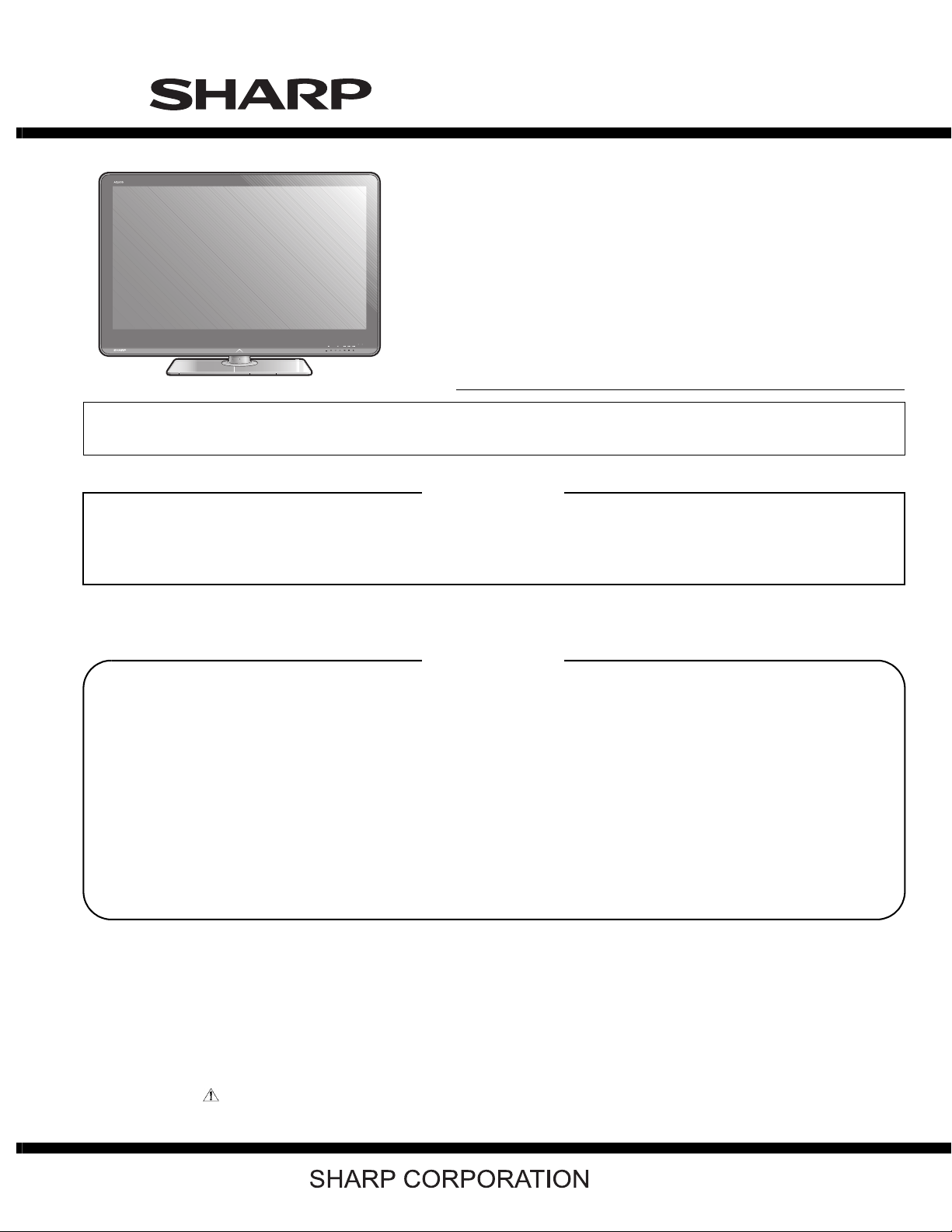
LC-40/46LX814E, LC-40/46LU824E
SERVICE MANUAL
No. S00N840LX814E
LCD COLOUR TELEVISION
LC-40LX814E
LC-46LX814E
LC-40LU824E
MODELS
In the interests of user-safety (Required by safety regulations in some countries) the set should be restored to its original condition and only parts identical to those specified should be used.
LC-46LU824E
OUTLINE
This Service Manual covers the differences from LC-40/46LE814E, LC-40/46LE824E.
For other technical information, refer to the LC-40/46LE814E, LC-40/46LE824E (No. S90K840LE814E) Service
Manual.
CONTENTS
OUTLINE AND DIFFERENCES FROM BASE MODEL
OUTLINE.................................................................... i
DIFFERENCES FROM BASE MODEL
(LC-40LX814E) .......................................................... i
DIFFERENCES FROM BASE MODEL
(LC-46LX814E) .......................................................... i
DIFFERENCES FROM BASE MODEL
(LC-40LU824E) ......................................................... ii
DIFFERENCES FROM BASE MODEL
(LC-46LU824E) ......................................................... ii
SAFETY PRECAUTION
IMPORTANT SERVICE SAFETY
PRECAUTION...........................................................iii
Precautions for using lead-free solder ..................... iv
End of life disposal.................................................... v
OUTLINE
MAJOR SERVICE PARTS ....................................... vi
Parts Guide
Parts marked with " " are important for maintaining the safety of the set. Be sure to replace these parts with specified ones for maintaining the
safety and performance of the set.
This document has been published to be used for
after sales service only.
The contents are subject to change without notice.
Page 2
LC-40/46LX814E, LC-40/46LU824E
LC-40/46LX814E, LC-40/46LU824E
OUTLINE AND DIFFERENCES FROM BASE MODEL
Service Manual
OUTLINE
This Service Manual covers the differences from LC-40/46LE814E, LC-40/46LE824E.
For other technical information, refer to the LC-40/46LE814E, LC-40/46LE824E (No. S90K840LE814E) Service Manual.
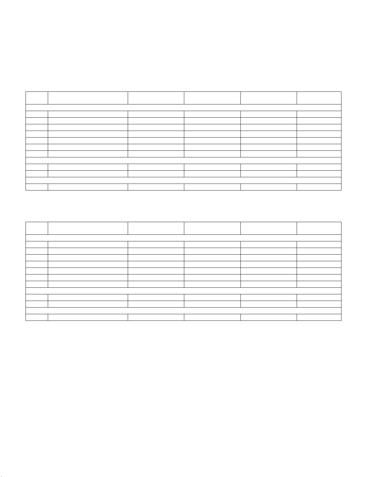
DIFFERENCES FROM BASE MODEL (LC-40LX814E)
Ref No. Description
PRINTED WIRING BOARD ASSEMBLIES
N MAIN Unit DKEYDF455FM11 ← — No change
N ICON Unit DUNTKF493FM03 ← — No change
N R/C, LED Unit DUNTKF494FM02 ← — No change
N POWER/LED CONTROL Unit RUNTKA685WJQZ ← — No change
N TOUCH SENSOR Unit RUNTKA692WJQZ ← — No change
N LCD CONTROL Unit RUNTK4512TPZC ← — No change
LCD PANEL MODULE
N 40” LCD Panel Module Unit R1LK400D3LWF2Y ← — No change
CABINET PARTS
1 Front Cabinet Ass'y CCABAC527WJ1A CCABAC527WJ1C D Changed
LC-40LE814E
(No. S90K840LE814E)
LC-40LX814E
(No. S00N840LX814E)
Interchangeability Note
DIFFERENCES FROM BASE MODEL (LC-46LX814E)
Ref No. Description
PRINTED WIRING BOARD ASSEMBLIES
N MAIN Unit DKEYDF455FM11 ← — No change
N ICON Unit DUNTKF493FM03 ← — No change
N R/C, LED Unit DUNTKF494FM02 ← — No change
N POWER/LED CONTROL Unit RUNTKA686WJQZ ← — No change
N TOUCH SENSOR Unit RUNTKA692WJQZ ← — No change
N LCD CONTROL Unit RUNTK4512TPZG ← — No change
LC-46LE814E
(No. S90K840LE814E)
LC-46LX814E
(No. S00N840LX814E)
Interchangeability Note
LCD PANEL MODULE
N 46” LCD Panel Module Unit R1LK460D3LWG2Y ← — No change
CABINET PARTS
1 Front Cabinet Ass'y CCABAC528WJ1A CCABAC528WJ1C D Changed
i
Page 3
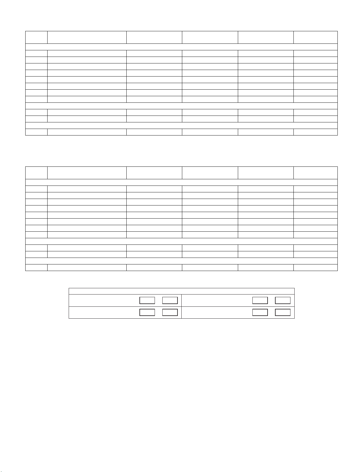
DIFFERENCES FROM BASE MODEL (LC-40LU824E)
LC-40/46LX814E, LC-40/46LU824E
Ref No. Description
PRINTED WIRING BOARD ASSEMBLIES
N MAIN Unit DKEYDF455FM12 ← — No change
N ICON Unit DUNTKF493FM03 ← — No change
N LOGO Unit DUNTKF493FM04 ← — No change
N R/C, LED Unit DUNTKF494FM02 ← — No change
N POWER/LED CONTROL Unit RUNTKA685WJQZ ← — No change
N TOUCH SENSOR Unit RUNTKA761WJQZ ← — No change
N LCD CONTROL Unit RUNTK4512TPZC ← — No change
LCD PANEL MODULE
N 40” LCD Panel Module Unit R1LK400D3LWF0Y ← — No change
CABINET PARTS
1 Front Cabinet Ass'y CCABAC621WJ12 CCABAC621WJ13 D Changed
LC-40LE824E
(No. S90K840LE814E)
LC-40LU824E
(No. S00N840LX814E)
Interchangeability Note
DIFFERENCES FROM BASE MODEL (LC-46LU824E)
Ref No. Description
PRINTED WIRING BOARD ASSEMBLIES
N MAIN Unit DKEYDF455FM12 ← — No change
N ICON Unit DUNTKF493FM03 ← — No change
N LOGO Unit DUNTKF493FM04 ← — No change
N R/C, LED Unit DUNTKF494FM02 ← — No change
N POWER/LED CONTROL Unit RUNTKA686WJQZ ← — No change
N TOUCH SENSOR Unit RUNTKA761WJQZ ← — No change
N LCD CONTROL Unit RUNTK4512TPZG ← — No change
LC-46LE824E
(No. S90K840LE814E)
LC-46LU824E
(No. S00N840LX814E)
Interchangeability Note
LCD PANEL MODULE
N 46” LCD Panel Module Unit R1LK460D3LWG0Y ← — No change
CABINET PARTS
1 Front Cabinet Ass'y CCABAC612WJ12 CCABAC612WJ13 D Changed
Interchangeability
Completely interchangeableA:
Interchangeable from
B:
OLD to NEW
ψ
=
NEWOLD
NEWOLD
Interchangeable from
C:
NEW to OLD
Not interchangeableD:
ψ
NEW OLD
X
OLDNEW
ii
Page 4
LC-40/46LX814E, LC-40/46LU824E
LC-40/46LX814E, LC-40/46LU824E
SAFETY PRECAUTION
Service Manual
IMPORTANT SERVICE SAFETY PRECAUTION
Service work should be performed only by qualified service technicians who are thoroughly familiar with all safety checks and the
servicing guidelines which follow:
WARNING
1. For continued safety, no modification of any circuit should be
attempted.
2. Disconnect AC power before servicing.
CAUTION:
FOR CONTINUED PROTECTION AGAINST A
RISK OF FIRE REPLACE ONLY WITH SAME
TYPE FUSE.
• Use an AC voltmeter having with 5000 ohm per volt, or higher, sensitivity or measure the AC voltage drop across the resistor.
• Connect the resistor connection to all exposed metal parts having a
return to the chassis (antenna, metal cabinet, screw heads, knobs
and control shafts, escutcheon, etc.) and measure the AC voltage
drop across the resistor.
All checks must be repeated with the AC cord plug connection
reversed. (If necessary, a nonpolarized adaptor plug must be used
only for the purpose of completing these checks.)
Any reading of 1.05 V peak (this corresponds to 0.7 mA peak AC.)
or more is excessive and indicates a potential shock hazard which
must be corrected before returning the monitor to the owner.
40 inch model: F7000, F7001 (3.15A/250V)
46 inch model: F7000, F7001 (5A/250V)
DVM
BEFORE RETURNING THE RECEIVER (Fire & Shock Hazard)
Before returning the receiver to the user, perform the following
safety checks:
3. Inspect all lead dress to make certain that leads are not pinched,
and check that hardware is not lodged between the chassis and
other metal parts in the receiver.
4. Inspect all protective devices such as non-metallic control knobs,
insulation materials, cabinet backs, adjustment and compartment
covers or shields, isolation resistor-capacitor networks, mechanical
insulators, etc.
5. To be sure that no shock hazard exists, check for leakage current in
the following manner.
• Plug the AC cord directly into a 220~240 volt AC outlet.
• Using two clip leads, connect a 1.5k ohm, 10 watt resistor paralleled by a 0.15µF capacitor in series with all exposed metal cabinet
parts and a known earth ground, such as electrical conduit or electrical ground connected to an earth ground.
///////////////////////////////////////////////////////////////////////////////////////////////////////////////////////////////////////////////////////////////////////////////////////////////////////////////////////////////////////////
TO EXPOSED
METAL PARTS
SAFETY NOTICE
Many electrical and mechanical parts in LCD colour television have
special safety-related characteristics.
These characteristics are often not evident from visual inspection, nor
can protection afforded by them be necessarily increased by using
replacement components rated for higher voltage, wattage, etc.
Replacement parts which have these special safety characteristics are
identified in this manual; electrical components having such features
are identified by “ ” and shaded areas in the Replacement Parts
List and Schematic Diagrams.
///////////////////////////////////////////////////////////////////////////////////////////////////////////////////////////////////////////////////////////////////////////////////////////////////////////////////////////////////////////
For continued protection, replacement parts must be identical to those
used in the original circuit.
The use of a substitute replacement parts which do not have the same
safety characteristics as the factory recommended replacement parts
shown in this service manual, may create shock, fire or other hazards.
AC SCALE
1.5k ohm
10W
0.15µF
TEST PROBE
CONNECT TO
KNOWN EARTH
GROUND
iii
Page 5
LC-40/46LX814E, LC-40/46LU824E
Precautions for using lead-free solder
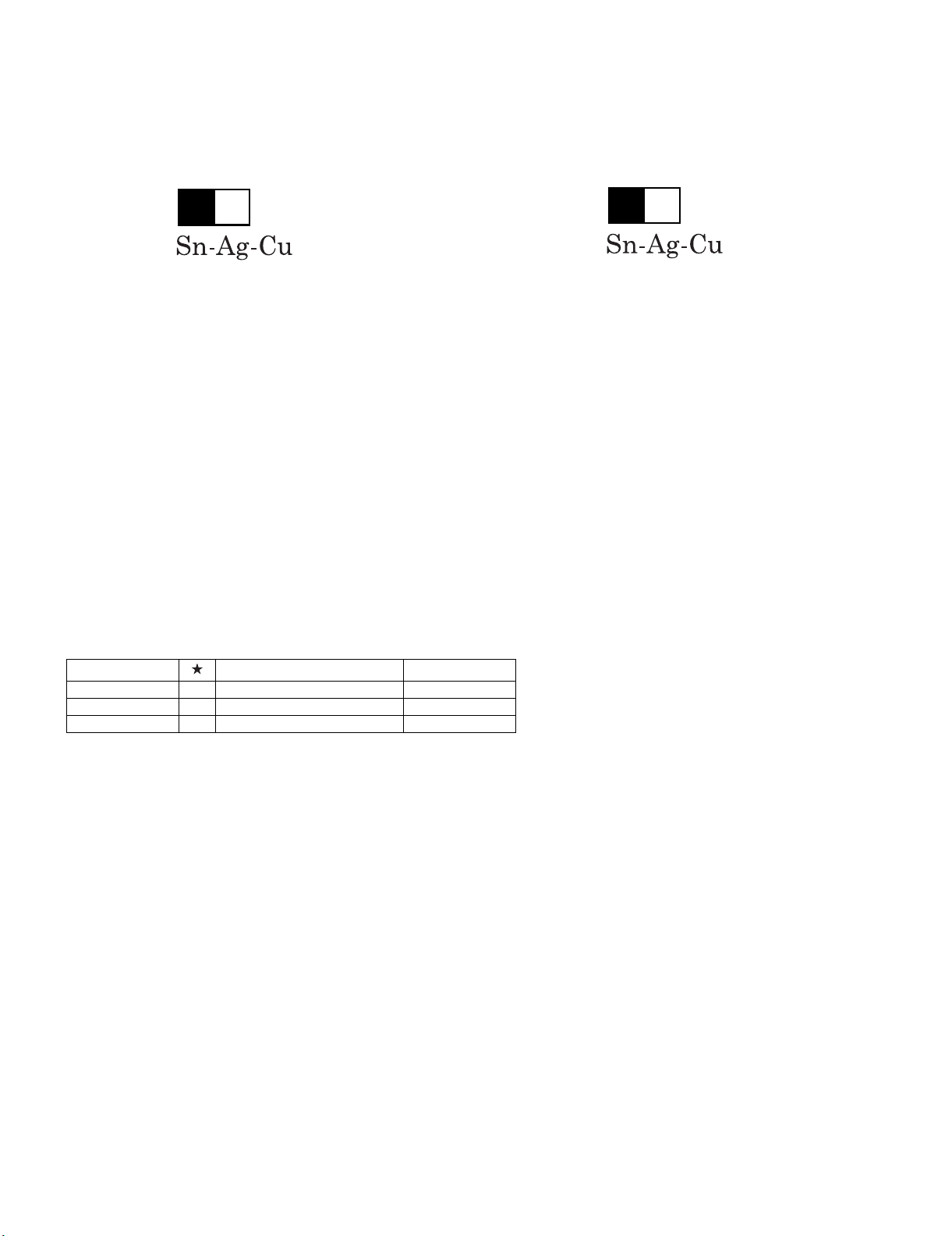
Employing lead-free solder
• “PWBs” of this model employs lead-free solder. The LF symbol indicates lead-free solder, and is attached on the PWBs and service manuals. The
alphabetical character following LF shows the type of lead-free solder.
Example:
L Fa
Indicates lead-free solder of tin, silver and copper.
Indicates lead-free solder of tin, silver and copper.
L F a/a
Using lead-free wire solder
• When fixing the PWB soldered with the lead-free solder, apply lead-free wire solder. Repairing with conventional lead wire solder may cause damage or accident due to cracks.
As the melting point of lead-free solder (Sn-Ag-Cu) is higher than the lead wire solder by 40 °C, we recommend you to use a dedicated soldering
bit, if you are not familiar with how to obtain lead-free wire solder or soldering bit, contact our service station or service branch in your area.
Soldering
• As the melting point of lead-free solder (Sn-Ag-Cu) is about 220 °C which is higher than the conventional lead solder by 40 °C, and as it has poor
solder wettability, you may be apt to keep the soldering bit in contact with the PWB for extended period of time. However, Since the land may be
peeled off or the maximum heat-resistance temperature of parts may be exceeded, remove the bit from the PWB as soon as you confirm the
steady soldering condition.
Lead-free solder contains more tin, and the end of the soldering bit may be easily corroded. Make sure to turn on and off the power of the bit as
required.
If a different type of solder stays on the tip of the soldering bit, it is alloyed with lead-free solder. Clean the bit after every use of it.
When the tip of the soldering bit is blackened during use, file it with steel wool or fine sandpaper.
• Be careful when replacing parts with polarity indication on the PWB silk.
Lead-free wire solder for servicing
Part No. Description Code
ZHNDAi123250E J φ0.3mm 250g (1roll) BL
ZHNDAi126500E J φ0.6mm 500g (1roll) BK
ZHNDAi12801KE J φ1.0mm 1kg (1roll) BM
iv
Page 6
LC-40/46LX814E, LC-40/46LU824E
End of life disposal
End of life disposal
v
Page 7
LC-40/46LX814E, LC-40/46LU824E
LC-40/46LX814E, LC-40/46LU824E
OUTLINE
Service Manual
MAJOR SERVICE PARTS
PWB UNIT
Ref No. Parts Code Description
N DKEYDF455FM11 MAIN Unit (LC-40LX814E)(LC-46LX814E) (*1)
N DKEYDF455FM12 MAIN Unit (LC-40LU824E)(LC-46LU824E) (*1)
N DUNTKF493FM03 ICON Unit
N DUNTKF493FM04 LOGO Unit (LC-40LU824E)(LC-46LU824E)
N DUNTKF494FM02 R/C, LED Unit
N RUNTKA685WJQZ POWER/LED CONTROL Unit (LC-40LX814E)(LC-40LU824E)
N RUNTKA686WJQZ POWER/LED CONTROL Unit (LC-46LX814E)(LC-46LU824E)
N RUNTKA692WJQZ TOUCH SENSOR Unit (LC-40LX814E)(LC-46LX814E)
N RUNTKA761WJQZ TOUCH SENSOR Unit (LC-40LU824E)(LC-46LU824E) (*2)
N RUNTK4512TPZC LCD CONTROL Unit (LC-40LX814E)(LC-40LU824E)
N RUNTK4512TPZG LCD CONTROL Unit (LC-46LX814E)(LC-46LU824E)
NOTE: (*1) Replace MAIN Unit (DKEYDF455FM11, DKEYDF455FM12) in case of IC8401 or IC3302 failure.
(*2) TOUCH SENSOR Unit (RUNTKA761WJQZ) reuse will be impossible, once it is stuck on front cabinet and exfoliates.
Therefore, please exchange of a TOUCH SENSOR Unit in the case of front cabinet exchange.
OTHER UNIT
Ref No. Parts Code Description
N R1LK400D3LWF2Y 40” LCD Panel Module Unit (LC-40LX814E)
N R1LK460D3LWG2Y 46” LCD Panel Module Unit (LC-46LX814E)
N R1LK400D3LWF0Y 40” LCD Panel Module Unit (LC-40LU824E)
N R1LK460D3LWG0Y 46” LCD Panel Module Unit (LC-46LU824E)
IC FOR EXCLUSIVE USE OF THE SERVICE
Ref No. Parts Code Description Q’ty
IC501 RH-iXD108WJQZS IC (EDID for PC) 1
IC2002 RH-iXC786WJNJQ IC (Monitor MICON) 1
SERVICE JIGS
Ref No. Parts Code Description Q’ty
N QCNW-G616WJQZ Main Unit to LCD Control Unit (LW) 1
N QCNW-G625WJQZ LCD Control Unit to Power Unit (PL) 1
N QCNW-H184WJQZ Main Unit to Power Unit (PD) 1
N QCNW-H185WJQZ Main Unit to Power Unit (LB) 1
N QCNW-K594WJQZ Main Unit to R/C, LED Unit (RA) 1
N QCNW-K595WJQZ Main Unit to Speaker (SP) 1
N QCNW-K596WJQZ Main Unit to LOGO Unit (RL) (LC-40LU824E)(LC-46LU824E) 1
N QCNW-K597WJQZ Main Unit to Woofer (SB) 1
vi
Page 8

LC-40/46LX814E, LC-40/46LU824E
vii
Page 9

PartsGuide
LC-40/46LX814E, LC-40/46LU824E
PARTS GUIDE
No. S00N840LX814E
LCD COLOUR TELEVISION
LC-40LX814E
LC-46LX814E
LC-40LU824E
CONTENTS
[1] PRINTED WIRING BOARD
ASSEMBLIES
[2] LCD PANEL MODULE
[3] CABINET PARTS (LC-40LX814E)
[4] CABINET PARTS (LC-46LX814E)
[5] CABINET PARTS (LC-40LU824E)
[6] CABINET PARTS (LC-46LU824E)
MODELS
LC-46LU824E
Parts marked with " " are important for maintaining the safety of the set. Be sure to replace these
parts with specified ones for maintaining the safety and performance of the set.
This document has been published to be used
for after sales service only.
The contents are subject to change without notice.
Page 10

LC-40/46LX814E, LC-40/46LU824E
NO. PARTS CODE
PRICE
RANK
[1] PRINTED WIRING BOARD ASSEMBLIES
N DKEYDF455FM11 CG N P MAIN Unit (LC-40LX814E)(LC-46LX814E)
N DKEYDF455FM12 CL N P MAIN Unit (LC-40LU824E)(LC-46LU824E)
N DUNTKF493FM03 AM N P ICON Unit
N DUNTKF493FM04 AN N P LOGO Unit (LC-40LU824E)(LC-46LU824E)
N DUNTKF494FM02 AP N P R/C, LED Unit
!
!
N RUNTKA685WJQZ BT N P POWER/LED CONTROL Unit (LC-40LX814E)(LC-40LU824E)
N RUNTKA686WJQZ BV N P POWER/LED CONTROL Unit (LC-46LX814E)(LC-46LU824E)
N RUNTKA692WJQZ AU N P TOUCH SENSOR Unit (LC-40LX814E)(LC-46LX814E)
N RUNTKA761WJQZ BC N P TOUCH SENSOR Unit (LC-40LU824E)(LC-46LU824E)
N RUNTK4512TPZC CA P LCD CONTROL Unit (LC-40LX814E)(LC-40LU824E)
N RUNTK4512TPZG N P LCD CONTROL Unit (LC-46LX814E)(LC-46LU824E)
[2] LCD PANEL MODULE
N R1LK400D3LWF2Y DM N P 40" LCD Panel Module Unit (LC-40LX814E)
N R1LK460D3LWG2Y DV N P 46" LCD Panel Module Unit (LC-46LX814E)
N R1LK400D3LWF0Y DM N P 40" LCD Panel Module Unit (LC-40LU824E)
N R1LK460D3LWG0Y DX N P 46" LCD Panel Module Unit (LC-46LU824E)
NEW
MARK
PAR T
DELIVERY
DESCRIPTION
2
Page 11

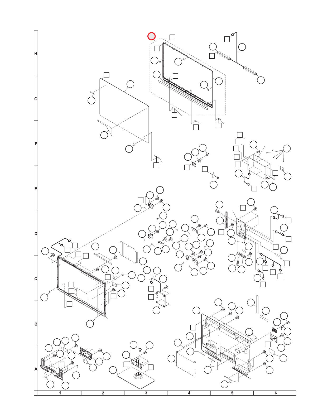
[3] CABINET PARTS (LC-40LX814E)
48
46
41
15
5
20
40
46
32
2-3
2-2
39
39
33
25
13
11
44
44
14
44
12
51
51
10
44
44
44
44
45
17
45
44
14
44
23
22
17
16
17
44
27
29
53
18
7
44
44
44
56
21
21
65
28
36
6
31
30
37
35
8
26
44
16
16
9
16
4
16
44
44
44
44
44
38
38
46
19
47
2
2-4
2-9
2-9
2-7
2-6
2-8
2-1
2-5
59
61
G
k
a
L
J
B
j
F
G
E
40" LCD
Panel Module Unit
g
f
h
K
POWER Unit
F
n
m
g
f
j
E
k
h
m
n
a
MAIN
Unit
d
b
p
K
C
C
B
X3
X3
X2
X1
A
A
X1
X3
Note:
Be sure to attach this insulation sheet. (Ref No. 2-6, 25, 53)
Otherwise there is a risk of electric shock.
Z
Z
1-1
1
R/C,
LED Unit
TOUCH
SENSOR
Unit
d
ICON
Unit
p
b
L
J
1-2
1-3
58
63
64
52
52
50
LC-40/46LX814E, LC-40/46LU824E
3
Page 12

LC-40/46LX814E, LC-40/46LU824E
NO. PARTS CODE
PRICE
RANK
NEW
MARK
PAR T
DELIVERY
[3] CABINET PARTS (LC-40LX814E)
1 CCABAC527WJ1C N P Front Cabinet Ass'y
DESCRIPTION
4
Page 13

[4] CABINET PARTS (LC-46LX814E)
48
50
43
16
48
21
49
74
74
5
72
48
40
46
40
17
9
52
46
46
17
4
46
17
22
42
37
46
31
29
33
57
7
39
23
6
46
30
38
34
32
46
46
71
70
73
66
69
67
68
23
8
28
46
1-1
41
41
35
47
47
46
13
46
19
19
12
46
46
10
55
47
25
24
11
46
46
19
19
19
19
46
15
14
46
27
46
46
46
61
65
63
64
B
G
h
F
k
j
POWER
Unit
g
f
m
MAIN
Unit
h
d
b
p
Z
k
a
E
K
m
a
L
C
C
46" LCD
Panel Module Unit
j
Y
G
g
f
B
F
J
E
K
X3
X3
X1
X2
A
A
X1
X3
Note:
Be sure to attach this insulation sheet. (Ref No. 27, 57, 71)
Otherwise there is a risk of electric shock.
Z
Y
1
R/C,
LED Unit
TOUCH
SENSOR
Unit
d
ICON
Unit
p
b
L
J
1-2
1-3
58
59
60
18
51
51
53
53
LC-40/46LX814E, LC-40/46LU824E
5
Page 14

LC-40/46LX814E, LC-40/46LU824E
NO. PARTS CODE
PRICE
RANK
NEW
MARK
PAR T
DELIVERY
[4] CABINET PARTS (LC-46LX814E)
1 CCABAC528WJ1C N P Front Cabinet Ass'y
DESCRIPTION
6
Page 15

[5] CABINET PARTS (LC-40LU824E)
48
46
41
15
5
20
40
46
32
2-3
2-2
39
39
33
1-4
1-5
1-1
3
25
13
11
44
44
14
44
12
10
44
44
44
44
45
17
45
44
14
44
23
22
49
49
17
16
17
44
27
29
53
7
44
44
44
56
21
21
65
28
36
6
31
30
34
37
35
8
26
44
16
16
9
16
4
16
44
44
44
44
44
38
38
46
19
47
2
2-4
2-9
2-9
2-7
2-6
2-8
2-1
2-5
59
61
G
k
a
L
H
L
R/C, LED Unit
LOGO
Unit
ICON
Unit
b
d
TOUCH
SENSOR
Unit
e
p
J
J
H
B
j
F
G
E
40" LCD
Panel Module Unit
g
f
h
K
POWER
Unit
F
n
m
g
f
j
E
k
h
m
n
a
MAIN
Unit
d
b
e
p
K
C
C
B
X3
X3
X2
X1
A
A
X1
X3
Note:
Be sure to attach this insulation sheet. (Ref No. 2-6, 25, 53)
Otherwise there is a risk of electric shock.
1-5
1-5
1-5
1-5
Z
Z
54
55
58
63
64
18
51
51
52
52
50
1
LC-40/46LX814E, LC-40/46LU824E
7
Page 16

LC-40/46LX814E, LC-40/46LU824E
NO. PARTS CODE
PRICE
RANK
NEW
MARK
PAR T
DELIVERY
[5] CABINET PARTS (LC-40LU824E)
1 CCABAC621WJ13 N P Front Cabinet Ass'y
DESCRIPTION
8
Page 17
[6] CABINET PARTS (LC-46LU824E)
48
50
43
16
48
21
49
74
74
5
72
48
40
46
40
17
9
52
46
46
17
4
46
17
22
42
37
46
31
29
33
57
7
39
23
6
46
30
38
34
32
36
46
60
46
71
70
73
66
69
67
68
23
8
28
46
1-4
1-5
1-5
1-5
3
59
1-1
41
41
35
47
47
46
46
13
46
19
19
12
46
46
10
55
47
25
24
11
46
46
19
19
19
51
51
19
46
15
14
54
54
46
27
56
46
46
46
61
65
63
64
B
G
h
F
k
j
POWER
Unit
g
f
m
MAIN
Unit
h
d
b
p
Z
k
a
e
E
K
m
J
H
J
L
LOGO
Unit
ICON
Unit
e
p
R/C, LED Unit
b
d
TOUCH
SENSOR
Unit
a
L
C
C
46" LCD
Panel Module Unit
j
Y
G
g
f
B
F
H
E
K
X3
X3
X1
X2
A
A
X1
X3
Note:
Be sure to attach this insulation sheet. (Ref No. 27, 57, 71)
Otherwise there is a risk of electric shock.
Z
Y
62
44
45
58
18
53
53
1
LC-40/46LX814E, LC-40/46LU824E
9
Page 18

LC-40/46LX814E, LC-40/46LU824E
NO. PARTS CODE
PRICE
RANK
NEW
MARK
PAR T
DELIVERY
[6] CABINET PARTS (LC-46LU824E)
1 CCABAC612WJ13 N P Front Cabinet Ass'y
DESCRIPTION
10
Page 19

MEMO
LC-40/46LX814E, LC-40/46LU824E
COPYRIGHT©XXXX BYSHARP CORPORATION
ALL RIGHTS RESERVED.
No part of this publication may be reproduced,
stored in a retrieval system, or transmitted in
any form or by any means, electronic, mechanical,
photocopying, recording, or otherwise, without
prior written permission of the publisher.
Page 20

LC-40/46LX814E, LC-40/46LU824E
COPYRIGHT 2010 BY SHARP CORPORATION
ALL RIGHTS RESERVED.
No part of this publication may be reproduced,
stored in a retrieval system, or transmitted in
any form or by any means, electronic, mechanical,
photocopying, recording, or otherwise, without
prior written permission of the publisher.
Oct. 2010
SH. KD
SHARP CORPORATION
AV Systems Group
CS Promotion Center
Yaita, Tochigi 329-2193, Japan
 Loading...