

Page 1
TopPage
xxxxxxxxx
LC-37SB24U
SERVICE MANUAL
No. S38H3LC37SB24
LCD COLOR TELEVISION
MODEL
In the interests of user-safety (Required by safety regulations in some countries) the set should be restored to its original condition and only parts identical to those specified should be used.
LC-37SB24U
OUTLINE
This Service Manual covers the differences from LC-37D44U. For other technical information, refer to the LC-37D44U
(No. S18D7LC37D44U) Service Manual.
CONTENTS
SAFETY PRECAUTION
IMPORTANT SERVICE SAFETY PRE-
CAUTION ............................................................i
PRECAUTIONS A PRENDRE LORS DE
LA REPARATION...............................................ii
OUTLINE AND MODIFIED PARTS LIST
OUTLINE ..........................................................iii
MODIFIED PARTS LIST...................................iii
Parts Guide
Parts marked with " " are important for maintaining the safety of the set. Be sure to replace these parts with specified ones for maintaining the
safety and performance of the set.
This document has been published to be used for
after sales service only.
The contents are subject to change without notice.
Page 2
LC-37SB24U
LC37SB24U
SAFETY PRECAUTION
Service Manual
IMPORTANT SERVICE SAFETY PRECAUTION
Service work should be performed only by qualified service technicians who are thoroughly familiar with all safety checks and the
servicing guidelines which follow:
WARNING
1. For continued safety, no modification of any circuit should be
attempted.
2. Disconnect AC power before servicing.
CAUTION: FO R C O N T I N U E D PROTECTION
AGAINST A RISK OF FIRE REPLACE ONLY WITH
SAME TYPE FUSE.
F7101 (250V 6.3A)
• Use an AC voltmeter having with 5000 ohm per volt, or higher, sensitivity or measure the AC voltage drop across the resistor.
• Connect the resistor connection to all exposed metal parts having a
return to the chassis (antenna, metal cabinet, screw heads, knobs
and control shafts, escutcheon, etc.) and measure the AC voltage
drop across the resistor.
All checks must be repeated with the AC cord plug connection
reversed. (If necessary, a nonpolarized adaptor plug must be used
only for the purpose of completing these checks.)
Any reading of 0.75 Vrms (this corresponds to 0.5 mA rms AC.) or
more is excessive and indicates a potential shock hazard which
must be corrected before returning the monitor to the owner.
F7102 (250V 1A)
DVM
BEFORE RETURNING THE RECEIVER (Fire &
Shock Hazard)
Before returning the receiver to the user, perform the following
safety checks:
3. Inspect all lead dress to make certain that leads are not pinched,
and check that hardware is not lodged between the chassis and
other metal parts in the receiver.
4. Inspect all protective devices such as non-metallic control knobs,
insulation materials, cabinet backs, adjustment and compartment
covers or shields, isolation resistor-capacitor networks, mechanical
insulators, etc.
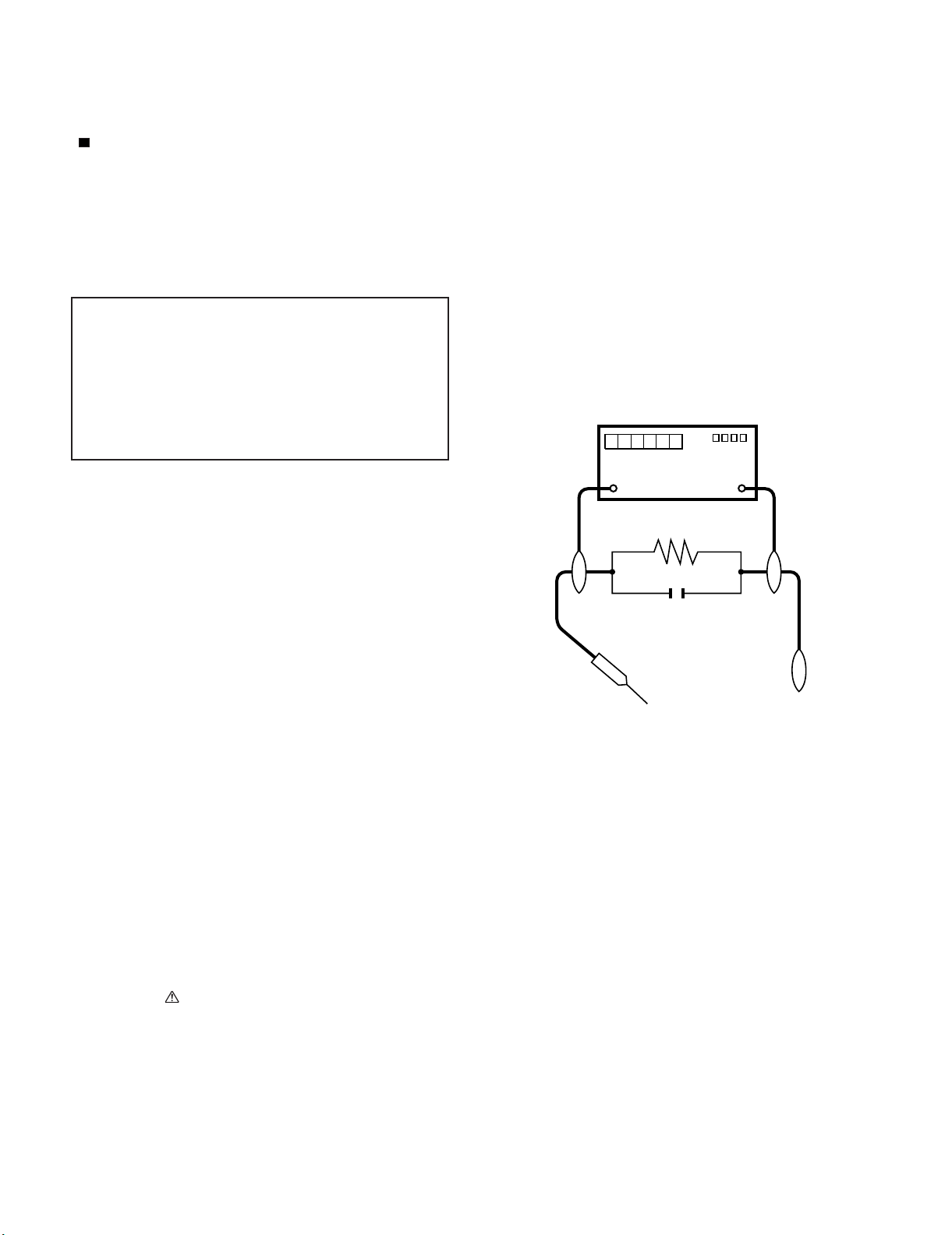
5. To be sure that no shock hazard exists, check for leakage current in
the following manner.
• Plug the AC cord directly into a 120 volt AC outlet.
• Using two clip leads, connect a 1.5k ohm, 10 watt resistor paralleled by a 0.15µF capacitor in series with all exposed metal cabinet
parts and a known earth ground, such as electrical conduit or electrical ground connected to an earth ground.
///////////////////////////////////////////////////////////////////////////////////////////////////////////////////////////////////////////////////////////////////////////////////////////////////////////////////////////////////////////
TO EXPOSED
METAL PARTS
AC SCALE
1.5k ohm
10W
0.15µF
TEST PROBE
CONNECT TO
KNOWN EARTH
GROUND
SAFETY NOTICE
Many electrical and mechanical parts in LCD color television have
special safety-related characteristics.
These characteristics are often not evident from visual inspection, nor
can protection afforded by them be necessarily increased by using
replacement components rated for higher voltage, wattage, etc.
Replacement parts which have these special safety characteristics are
identified in this manual; electrical components having such features
are identified by " " and shaded areas in the Replacement Parts List
and Schematic Diagrams.
///////////////////////////////////////////////////////////////////////////////////////////////////////////////////////////////////////////////////////////////////////////////////////////////////////////////////////////////////////////
For continued protection, replacement parts must be identical to those
used in the original circuit.
The use of a substitute replacement parts which do not have the same
safety characteristics as the factory recommended replacement parts
shown in this service manual, may create shock, fire or other hazards.
i
Page 3
LC-37SB24U
PRECAUTIONS A PRENDRE LORS DE LA REPARATION
Ne peut effectuer la réparation qu' un technicien spécialisé qui s'est parfaitement accoutumé à toute vérification de sécurité et aux
conseils suivants.
•
AVERTISSEMENT
1.
N'entreprendre aucune modification de tout circuit. C'est dangereux.
2.
Débrancher le récepteur avant toute réparation.
PRECAUTION: POUR LA PROTECTION CONTINUE CONTRE LES RISQUES D'INCENDIE,
REMPLACER LE FUSIBLE
F7101 (250V 6.3A)
F7102 (250V 1A)
VERIFICATIONS CONTRE L'INCEN-DIE ET LE
CHOC ELECTRIQUE
Avant de rendre le récepteur à l'utilisateur, effectuer les vérifications suivantes.
Inspecter tous les faisceaux de câbles pour s'assurer que les fils
3.
ne soient pas pincés ou qu'un outil ne soit pas placé entre le châssis et les autres pièces métalliques du récepteur.
4.
Inspecter tous les dispositifs de protection comme les boutons de
commande non-métalliques, les isolants, le dos du coffret, les couvercles ou blindages de réglage et de compartiment, les réseaux
de résistancecapacité, les isolateurs mécaniques, etc.
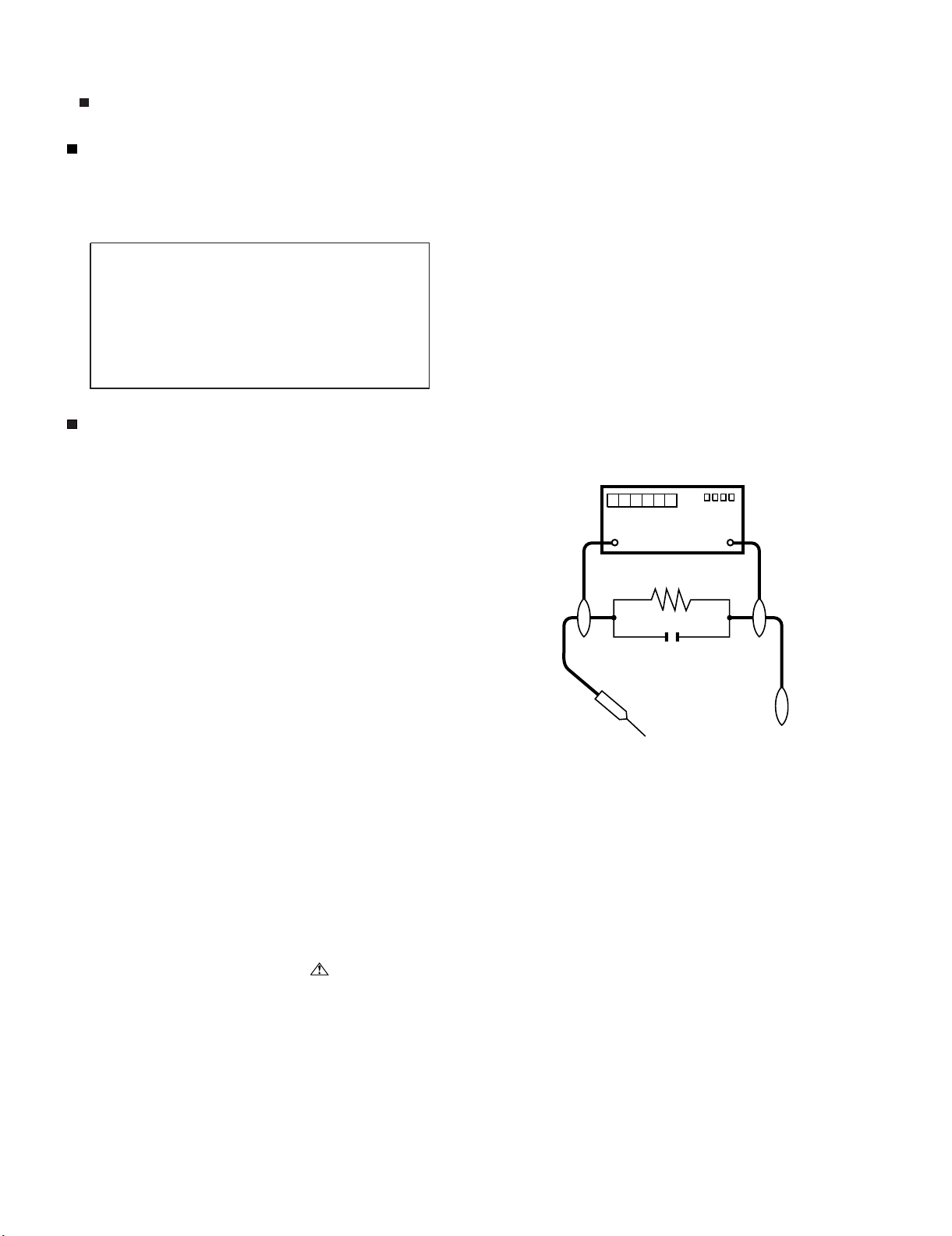
5.
S'assurer qu'il n'y ait pas de danger d'électrocution en vérifiant la
fuite de courant, de la facon suivante:
•
Brancher le cordon d'alimentation directem-ent à une prise de courant de 120V. (Ne pas utiliser de transformateur d'isolation pour
cet essai).
A l'aide de deux fils à pinces, brancher une résistance de 1.5 kΩ
10 watts en parallèle avec un condensateur de 0.15µF en série
avec toutes les pièces métalliques exposées du coffret et une terre
connue comme une conduite électrique ou une prise de terre
branchée à la terre.
•
Utiliser un voltmètre CA d'une sensibilité d'au moins 5000Ω/V pour
mesurer la chute de tension en travers de la résistance.
•
Toucher avec la sonde d'essai les pièces métalliques exposées qui
présentent une voie de retour au châssis (antenne, coffret métallique, tête des vis, arbres de commande et des boutons, écusson,
etc.) et mesurer la chute de tension CA en-travers de la résistance.
Toutes les vérifications doivent être refaites après avoir inversé la
fiche du cordon d'alimentation. (Si nécessaire, une prise
d'adpatation non polarisée peut être utilisée dans le but de terminer ces vérifications.)
La tension de pointe mesurèe ne doit pas dépasser 0.75V (correspondante au courant CA de pointe de 0.5mA).
Dans le cas contraire, il y a une possibilité de choc électrique qui
doit être supprimée avant de rendre le récepteur au client.
DVM
ECHELLE CA
1.5k ohm
10W
µ
F
0.15
SONDE D'ESSAI
AUX PIECES
METALLIQUES
EXPOSEES
/////////////////////////////////////////////////////////////////////////////////////////////////////////////////////////////////////////////////////////////////////////////////////////////////////////////////////////////////////////////
BRANCHER A UNE
TERRE CONNUE
AVIS POUR LA SECURITE
De nombreuses pièces, électriques et mécaniques, dans les téléviseur ACL présentent des caractéristiques spéciales relatives à la sécurité, qui ne sont souvent pas évidentes à vue. Le degré de protection ne peut pas être nécessairement augmentée en utilisant des
pièces de remplacement étalonnées pour haute tension, puissance,
etc.
Les pièces de remplacement qui présentent ces caractéristiques sont
identifiées dans ce manuel; les pièces électriques qui présentent ces
particularités sont identifiées par la marque " " et hachurées dans la
liste des pièces de remplacement et les diagrammes schématiques.
/////////////////////////////////////////////////////////////////////////////////////////////////////////////////////////////////////////////////////////////////////////////////////////////////////////////////////////////////////////////
Pour assurer la protection, ces pièces doivent être identiques à celles
utilisées dans le circuit d'origine. L'utilisation de pièces qui n'ont pas
les mêmes caractéristiques que les pièces recommandées par l'usine,
indiquées dans ce manuel, peut provoquer des électrocutions, incendies, radiations X ou autres accidents.
ii
Page 4

LC-37SB24U
LC37SB24U
OUTLINE AND MODIFIED PARTS LIST
Service Manual
OUTLINE
This Service Manual covers the differences from LC-37D44U. For other technical information, refer to the LC-37D44U (No. S18D7LC37D44) Service
Manual.
MODIFIED PARTS LIST
Ref.No. Description No. S18D7LC37D44U (Base Models) No. S38H3LC37SB24 (This Model) Remarks
PRINTED WIRING BOARD ASSEMBLIES
N R/C, LED Unit DUNTKE264FM02 DUNTKE264FM02 No Changes
N KEY Unit DUNTKE266FM02 DUNTKE266FM02 No Changes
N MAIN Unit DUNTKE450FM01 DUNTKE450FM01 No Changes
N POWER Unit RDENCA272WJQZ RDENCA272WJQZ No Changes
N INVERTER Unit RUNTKA418WJQZ RUNTKA418WJQZ No Changes
LCD PANEL
N 37" Wide LCD Panel Module Unit R1LK370T3GW20Z R1LK370T3GW20Z No Changes
CABINET PARTS
Refer to Parts List.
SUPPLIED ACCESSORIES
Refer to Parts List.
PAC K I NG PAR T S
Refer to Parts List.
Service Jigs
No Changes
iii
Page 5

PartsGuide
LC-37SB24U
PARTS GUIDE
No. S38H3LC37SB24
LCD COLOR TELEVISION
Note:
The reference numbers on the PWB
are arranged in alphabetical order.
[1] CABINET AND MECHANICAL
PARTS
[2] SUPPLIED ACCESSORIES
MODEL
CONTENTS
LC-37SB24U
[3] PACKING PARTS
(NOT REPLACEMENT ITEM)
Parts marked with " " are important for maintaining the safety of the set. Be sure to replace these
parts with specified ones for maintaining the safety and performance of the set.
This document has been published to be used
for after sales service only.
The contents are subject to change without notice.
Page 6

LC-37SB24U
[1] CABINET AND MECHANICAL PARTS
7
1-5
1-1
1-8
38
1-5
1-5
1-9
1-7
1-4
1-2
32
1
1-5
1-5
1-7
34
KEY Unit
45
30
1-5
1-3
13
34
35
INVERTER Unit
31
R/C, LED Unit
42
2
20
45
36
37
3
49
36
37
39
6
2-2
27
41
POWER Unit
43
45
38
26
33
17
12
45
10
19
45
45
14
28
12
14
21
14
18
43
11
24
45
45
44
MAIN Unit
4
40
2-1
21
9
46
29
22
23
45
45
25
46
47
17
47-2
47-1
47-3
42
5
48
45
11
43
16
16
10
8
45
43
47-3
2
Page 7

LC-37SB24U
NO. PARTS CODE
PRICE
RANK
NEW
MARK
PAR T
DELIVERY
[1] CABINET AND MECHANICAL PARTS
1 CCABAC052WJ31 BV N X Front Cabinet Ass'y
1-1 Not Available - N - Front Cabinet
1-2 Not Available - N - 37" Centert Dec.
1-3 Not Available - - LED Dec.
1-4 HPNLSA173WJKA AS N X Speaker Net
1-5 PSPAHB408WJZZ AC X Spacer, x6
1-6 Not Available - - Spacer
1-7 PSPAZB833WJZZ AD X Speaker Spacer
1-8 TLABZA635WJZZ AC J E-Star Label
1-9 XJPSN30P08XS0 AA J Screw, x3
2 CCABBB272WJ01 N X Rear Cabinet Ass'y
2-1 Not Available - N - Rear Cabinet
2-2 HINDPC686WJSA AG X Terminal Label
3 R1LK370T3GW20Z EC N J 37" Wide LCD Panel Module Unit
4 GCOVAC612WJ3A AK N X Bottom Cover
5 HINDPB715WJSA AF X Terminal Label
6 HINDPC788WJSA AE N X Model Label
7 JBTN-A718WJ3A AF X Operation Button
8 LANGKB343WJZZ AR N X Stand Fix Angle
9 LANGKB346WJFW AH N X Heat Sink Fix Angle
10 LANGKB366WJFW AD N X LCD Fix Angle-T, x2
11 LANGKB367WJFW AD N X LCD Fix Angle-B, x2
12 LANGTA478WJZZ AR N X VESA Angle-L, x2
13 PSLDMB359WJZZ AG N X Shield
14 LHLDWA143WJKZ AC J Wire Holder, x3
16 LHLDWA175WJUZ AC J Wire Holder, x2
17 LHLDZA928WJ3Z AG N X Main PWB Holder, x2
18 LHLDZA933WJKZ AB N J Wire Holder
19 LHLDZA934WJKZ AB N J Wire Holder, x6
20 NSFTZ0134CEFW AD J Shaft (for DVI), x2
21 PCLICA004WJKZ AC J Rivet, x4
22 PMLT-A534WJZZ AC N X Absorber
23 PMLT-A533WJZZ AD N X Absorber
24 PRDARA495WJFW AH X
25 PRDARA510WJFW AR X Heat Sink A
26 PSLDMB275WJZZ AQ N X Main Shield
27 PSPAKA237WJ00 AA X Spacer, x4
28 PSPAZB086WJKZ AD J Spacer, x2
29 PSPAZA917WJKZ AH J Spacer
30 QCNW-G729WJQZ AF N X Connecting Cord (KEY - MAIN)
31 QCNW-G730WJQZ AK N X Connecting Cord (LED - MAIN)
32 QCNW-H284WJPZ AL N X Connecting Cord (SP - MAIN)
33 QCNW-G732WJQZ AM N X Connecting Cord (POWER - MAIN)
34 PSLDMB360WJZZ AE N X Shield
35 PSPAZB202WJKZ AB J Spacer (for INV PWB)
36 QPWBME513WJPZ AQ N X Connecting Cord (LCD-FPC-MAIN), x2
37 RCORFA061WJZZ AG J Core, x2
38 RSP-ZA310WJZZ AQ N X Speaker (L/R), x2
39 Not Available - N - Serial No. Label (Back)
40 XBPS830P06000 AA J Screw (for HDMI), x2
41 XEBS930P10000 AA J Screw (for S-Terminal)
42 XEBS940P16000 AB J Screw (for CAB A B), x4
43 XEBSN40P10000 AB J Screw (for CAB A PANEL), x4
44 XHPS730P16WS0 AB N J Screw (for MAIN PWB), x4
45 XHPS830P06WS0 AA N J Screw (for Heat Sink), x32
46 XHPS830P10WS0 AB J Screw (for MAIN PWB2), x2
47 CDAI-A441WJ03 BF N X Stand Unit
47-1 Not Available - N - Stand Base Ass'y
47-2 Not Available - N - Stand Support Ass'y
47-3 Not Available - N - Screw (for Stand), x9
48 Not Available - N - Serial No. Label (Side)
49 XBPS940P10JS0 AB J Screw (for CAB B Chassis), x6
Heat Sink B
DESCRIPTION
3
Page 8

LC-37SB24U
[2] SUPPLIED ACCESSORIES
X3
X2X9
X4
NO. PARTS CODE
[2] SUPPLIED ACCESSORIES
X1 LHLDWA173WJKZ AE J Cable Clamp
!
X2 QACCDA039WJPZ AQ J AC Cord
X3 RRMCGA667WJSA AP N X Remote Control Unit
X4 TCADEA243WJZZ AD N X Enquete Card
X5 TCAUHA367WJZZ AD N X Child Safety Card
X6 TINS-D600WJZZ AE N X Operation Manual (English)
X7 TINS-D601WJZZ AE N X Operation Manual (French)
X8 TINS-D602WJZZ AE N X Operation Manual (Spanish)
X9 Not Available - - "AA" Size Batteries
X10 CDAI-A441WJ03 BF N X Stand Unit
X10-1 Not Available - N - Tool for Stand
X5
PRICE
RANK
NEW
MARK
PAR T
DELIVERY
X1
X10
X10-1
DESCRIPTION
X6
X7
X8
4
Page 9

[3] PACKING PARTS (NOT REPLACEMENT ITEM)
S8
S9
S7
S7
S3
LC-37SB24U
S4
S5
S6
S10
S2
S7
S7
S1
NO. PARTS CODE
PRICE
RANK
NEW
MARK
PAR T
DELIVERY
[3] PACKING PARTS (NOT REPLACEMENT ITEM)
S1 SPAKCE165WJZZ - N - Packing Case
S2 SPAKCE206WJZZ - N - Stand Case
S3 SPAKPB046WJZZ - - Wrapping Paper
S4 SPAKPB053WJZZ - N - Mirror Mat Sup
S5 SPAKPB054WJZZ - N - Mirror Mat Base
S6 SPAKAA373WJZZ - N - Cover Sheet
S7 SPAKXB804WJZZ - - Packing Add.
S8 SSAKA0101GJZZ - - Polyethylene Bag
S9 SSAKAA032WJZZ - - Polyethylene Bag
S10 SSAKHA042WJZZ - N - Polyethylene Bag for Screw
S11 TLABKA009WJZZ - - No. Label
S11
DESCRIPTION
5
Page 10

LC-37SB24U
COPYRIGHT © 2008 BY SHARP CORPORATION
ALL RIGHTS RESERVED.
No Part of this publication may be reproduced,
stored in a retrieval system, or transmitted in
any from or by any means, electronic, mechanical,
photocopying, recording, or otherwise, without
prior written permission of the publisher.
Mar. 2008
TQ2473-S SH. DS
SHARP CORPORATION
AV Systems Group
CS Promotion Center
Yaita,Tochigi 329-2193, Japan
 Loading...