

Page 1

LC-37HV4E
LCD COLOUR TELEVISION
LCD-FARBFERNSEHGERÄT
ENGLISH
DEUTSCH
TÉLÉVISION COULEUR À ÉCRAN
À CRISTAUX LIQUIDES (LCD)
OPERATION MANUAL
BEDIENUNGSANLEITUNG
MODE D’EMPLOI
FRANÇAIS
Page 2

This equipment complies with the requirements of Directive 89/336/EEC and 73/23/EEC as amended by 93/68/
EEC.
Dieses Gerät entspricht den Anforderungen der EG-Richtlinien 89/336/EWG und 73/23/EWG mit Änderung 93/
68/EWG.
Ce matériel répond aux exigences contenues dans les directives 89/336/CEE et 73/23/CEE modifiées par la
directive 93/68/CEE.
Dit apparaat voldoet aan de eisen van de richtlijnen 89/336/EEG en 73/23/EEG, gewijzigd door 93/68/EEG.
Dette udstyr overholder kravene i direktiv nr. 89/336/EEC og 73/23/EEC med tillæg nr. 93/68/EEC.
Quest’ apparecchio è conforme ai requisiti delle direttive 89/336/EEC e 73/23/EEC, come emendata dalla
direttiva 93/68/EEC.
« В„Н·Щ‹ЫЩ·ЫБ ·ıЩfi ·МЩ·ФНТflМВЩ·И ЫЩИЪ ··ИЩfiЫВИЪ Щ˘М Ф‰Б„И˛М ЩБЪ EıТ˘·˙НfiЪ EМ˘ЫБЪ 89/336/EOK Н·И
73/23/EOK, ¸˘Ъ ФИ Н·МФМИЫПФfl ·ıЩФfl ЫıПОБТ˛ЛБН·М ·¸ ЩБМ Ф‰Б„fl· 93/68/EOK.
Este equipamento obedece às exigências das directivas 89/336/CEE e 73/23/CEE, na sua versão corrigida pela
directiva 93/68/CEE.
Este aparato satisface las exigencias de las Directivas 89/336/CEE y 73/23/CEE, modificadas por medio de la
93/68/CEE.
Denna utrustning uppfyller kraven enligt riktlinjerna 89/336/EEC och 73/23/EEC så som kompletteras av 93/68/
EEC.
Dette produktet oppfyller betingelsene i direktivene 89/336/EEC og 73/23/EEC i endringen 93/68/EEC.
Tämä laite täyttää direktiivien 89/336/EEC ja 73/23/EEC vaatimukset, joita on muutettu direktiivillä 93/68/EEC.
SPECIAL NOTE FOR USERS IN THE U.K.
The mains lead of this product is fitted with a non-rewireable (moulded) plug incorporating a 3A fuse. Should
the fuse need to be replaced, a BSI or ASTA approved BS 1362 fuse marked
as above, which is also indicated on the pin face of the plug, must be used.
Always refit the fuse cover after replacing the fuse. Never use the plug without the fuse cover fitted.
In the unlikely event of the socket outlet in your home not being compatible with the plug supplied, cut off the
mains plug and fit an appropriate type.
DANGER:
The fuse from the cut-off plug should be removed and the cut-off plug destroyed immediately and disposed of
in a safe manner.
Under no circumstances should the cut-off plug be inserted elsewhere into a 13A socket outlet, as a serious
electric shock may occur.
To fit an appropriate plug to the mains lead, follow the instructions below:
IMPORTANT:
The wires in the mains lead are coloured in accordance with the following code:
Blue: Neutral
Brown: Live
As the colours of the wires in the mains lead of this product may not correspond with the coloured markings
identifying the terminals in your plug, proceed as follows:
• The wire which is coloured blue must be connected to the plug terminal which is marked N or coloured black.
• The wire which is coloured brown must be connected to the plug terminal which is marked L or coloured red.
Ensure that neither the brown nor the blue wire is connected to the earth terminal in your three-pin plug.
Before replacing the plug cover make sure that:
• If the new fitted plug contains a fuse, its value is the same as that removed from the cut-off plug.
• The cord grip is clamped over the sheath of the mains lead, and not simply over the lead wires.
IF YOU HAVE ANY DOUBT, CONSULT A QUALIFIED ELECTRICIAN.
or and of the same rating
Page 3

LC-37HV4E
LCD COLOUR TELEVISION
ENGLISH
OPERATION MANUAL
Contents
Contents …………………………………………………… 1
Dear SHARP customer …………………………………… 2
Important Safety Precautions ………………………… 2
Supplied accessories …………………………………… 4
Preparation ………………………………………………… 5
Attaching the speakers ……………………………… 5
Where to place the System…………………………… 6
Setting the System …………………………………… 7
Setting the Display on the wall ……………………… 9
Setting the AVC System with the stand …………… 9
Inserting the batteries ………………………………… 10
Using the remote control unit ………………………… 10
Cautions regarding remote control unit ……… 10
Part names …………………………………………………11
Display ………………………………………………… 11
AVC System …………………………………………… 12
Remote control unit …………………………………… 13
Watching TV ……………………………………………… 14
Basic connection ……………………………………… 14
Connecting to an antenna ……………………… 14
Connecting to the power outlet ………………… 14
Turning on the power ………………………………… 15
Turning off the power ………………………………… 15
Initial auto installation ………………………………… 16
Simple button operations for changing channels … 18
Using Flashback (A) on the remote control unit … 18
Simple button operation for changing
volume/sound …………………………………… 19
Basic adjustment settings ………………………………22
AV input mode menu items …………………………… 22
PC input mode menu items ………………………… 22
Auto installation ……………………………………… 23
Programme setup……………………………………… 24
Auto search ……………………………………… 24
Manual setting for each channel ……………… 25
Fine tuning …………………………………… 26
Colour system ……………………………… 27
Sound system (Broadcasting system) …… 27
Labelling channels ………………………… 27
Skipping channels ………………………… 28
Setting the decoder ………………………… 28
Setting the child lock ……………………… 28
Sort ………………………………………………… 29
Language setting for on-screen display …………… 30
Picture adjustments …………………………………… 31
C.M.S. (Colour Management System) ………… 32
Colour temperature ……………………………… 33
Black ……………………………………………… 33
Monochrome ……………………………………… 34
Film mode ………………………………………… 34
I/P setting ………………………………………… 35
DNR (Digital Noise Reduction) ………………… 35
Audio adjustment ……………………………………… 36
Sound adjustment ……………………………… 36
Surround…………………………………………… 36
ENGLISH
Power control ………………………………………… 37
Power control for AV source …………………… 37
Power control for PC source …………………… 39
Using external equipment ……………………………… 40
Watching a decoder image ………………………… 41
Connecting a decoder …………………………… 41
Displaying a programme ………………………… 41
Watching a VCR image ……………………………… 42
Connecting a VCR ……………………………… 42
Displaying a VCR image ………………………… 42
Using AV Link function ……………………………… 43
Watching a DVD image ……………………………… 44
Connecting a DVD player ……………………… 44
Displaying a DVD image ………………………… 44
Enjoying a game console and viewing camcorder
images …………………………………………… 45
Connecting a game console or camcorder …… 45
Displaying an image of the game console or
camcorder …………………………………… 45
Viewing an image from a PC ………………………… 46
Connecting a PC ………………………………… 46
Displaying an image from a PC ………………… 46
Connecting external speakers ……………………… 47
Selecting speakers ……………………………… 48
Useful adjustment settings ………………………………49
Image position (for TV/AV input mode) ……………… 49
Moving the picture on the screen …………………… 50
Auto Sync. adjustment (PC input mode only) ……… 51
Fine Sync. adjustment (PC input mode only) ……… 51
Input signal source …………………………………… 52
Colour system setting (for TV/AV input mode) …… 53
AV mode selection …………………………………… 53
WIDE mode (for TV/AV input mode) ………………… 54
WIDE mode (for PC input mode) …………………… 55
Input signal (PC input mode only) …………………… 56
Wide screen signalling (WSS)
(for TV/AV input mode) …………………………… 57
Picture aspect ratio (for TV/AV input mode) ……… 57
Rotate …………………………………………………… 58
Audio out ……………………………………………… 59
Sleep timer …………………………………………… 59
Cool climate …………………………………………… 60
Password setting for child lock
(for TV/AV input mode) …………………………… 61
Useful features …………………………………………… 62
Dual screen functions ………………………………… 62
Teletext function ……………………………………… 64
Appendix ………………………………………………… 67
Troubleshooting ……………………………………… 67
PC compatibility chart ………………………………… 68
RS-232C port specifications ………………………… 69
Connecting pin assignments for SCART …………… 71
Specifications ………………………………………… 72
Optional accessories ………………………………… 72
Dimensional drawings …………………………………… 73
1
Page 4

Dear SHARP customer
Thank you for your purchase of the SHARP LCD colour TV product. To ensure safety and many years of troublefree operation of your product, please read the Important Safety Precautions carefully before using this product.
Important Safety Precautions
Electricity is used to perform many useful functions, but it can also cause personal injuries and property
damage if improperly handled. This product has been engineered and manufactured with the highest
priority on safety. However, improper use can result in electric shock and/or fire. In order to prevent potential
danger, please observe the following instructions when installing, operating and cleaning the product. To
ensure your safety and prolong the service life of your LCD colour TV product, please read the following
precautions carefully before using the product.
1. Read instructions—All operating instructions must be read and understood before the product is operated.
2. Keep this manual in a safe place—These safety and operating instructions must be kept in a safe place for
future reference.
3. Observe warnings—All warnings on the product and in the instructions must be observed closely.
4. Follow instructions—All operating instructions must be followed.
5. Attachments—Do not use attachments not recommended by the manufacturer. Use of inadequate attachments
can result in accidents.
6. Power source—This product must operate on a power source specified on the specification label. If you are
not sure of the type of power supply used in your home, consult your dealer or local power company.
7. AC cord protection—The AC cords must be routed properly to prevent people from stepping on them or
objects from resting on them. Check the cords at the plugs and product.
8. Overloading—Do not overload AC outlets or extension cords. Overloading can cause fire or electric shock.
9. Entering of objects and liquids—Never insert an object into the product through vents or openings. High
voltage flows in the product, and inserting an object can cause electric shock and/or short internal parts. For
the same reason, do not spill water or liquid on the product.
10. Servicing—Do not attempt to service the product yourself. Removing covers can expose you to high voltage
and other dangerous conditions. Request a qualified service person to perform servicing.
11. Repair—If any of the following conditions occurs, unplug the AC cord from the AC outlet, and request a
qualified service person to perform repairs.
a. When the AC cord or plug is damaged.
b. When a liquid was spilled on the product or when objects have fallen into the product.
c. When the product has been exposed to rain or water.
d. When the product does not operate properly as described in the operating instructions.
Do not touch the controls other than those described in the operating instructions. Improper adjustment
of controls not described in the instructions can cause damage, which often requires extensive adjustment
work by a qualified technician.
e. When the product has been dropped or damaged.
f. When the product displays an abnormal condition. Any noticeable abnormality in the product indicates
that the product needs servicing.
12. Replacement parts—In case the product needs replacement parts, make sure that the service person uses
replacement parts specified by the manufacturer, or those with the same characteristics and performance as
the original parts. Use of unauthorized parts can result in fire, electric shock and/or other danger.
13. Safety checks—Upon completion of service or repair work, request the service technician to perform safety
checks to ensure that the product is in proper operating condition.
14. Wall or ceiling mounting—When mounting the product on a wall or ceiling, be sure to install the product
according to the method recommended by the manufacturer.
15. Unplug the AC cord from the AC outlet before installing the speakers.
2
Page 5

Important Safety Precautions
• Cleaning—Unplug the AC cord from the AC outlet before cleaning the product.
Use a damp cloth to clean the product. Do not use liquid cleaners or aerosol
cleaners.
• Water and moisture—Do not use the product near water, such as bathtub,
washbasin, kitchen sink, laundry tub, swimming pool and in a wet basement.
• Stand—Do not place the product on an unstable cart, stand, tripod or table. Doing
so can cause the product to fall, resulting in serious personal injuries as well as
damage to the product. Use only a cart, stand, tripod, bracket or table recommended
by the manufacturer or sold with the product. When mounting the product on a
wall, be sure to follow the manufacturer’s instructions. Use only the mounting
hardware recommended by the manufacturer.
• When relocating the product placed on a cart, it must be moved with utmost care.
Sudden stops, excessive force and uneven floor surface can cause the product to
fall from the cart.
• Ventilation—The vents and other openings in the cabinet are designed for ventilation.
Do not cover or block these vents and openings since insufficient ventilation can
cause overheating and/or shorten the life of the product. Do not place the product
on a bed, sofa, rug or other similar surface, since they can block ventilation openings.
This product is not designed for built-in installation; do not place the product in an
enclosed place such as a bookcase or rack, unless proper ventilation is provided
or the manufacturer’s instructions are followed.
• The LCD panel used in this product is made of glass. Therefore, it can break when
the product is dropped or applied with impact. Be careful not to be injured by
broken glass pieces in case the LCD panel breaks.
• Heat sources—Keep the product away from heat sources such as radiators, heaters,
stoves and other heat-generating products (including amplifiers).
The LCD panel is a very high technology product with 3,147,264 thin film transistors, giving you fine picture
details.
Occasionally, a few non-active pixels may appear on the screen as a fixed point of blue, green or red.
Please note that this does not affect the performance of your product.
Precautions when transporting the Display
When transporting the Display, never carry it by holding onto the speakers. Be sure to always carry the
Display by two people holding it with two hands—one hand on each side of the display.
3
Page 6
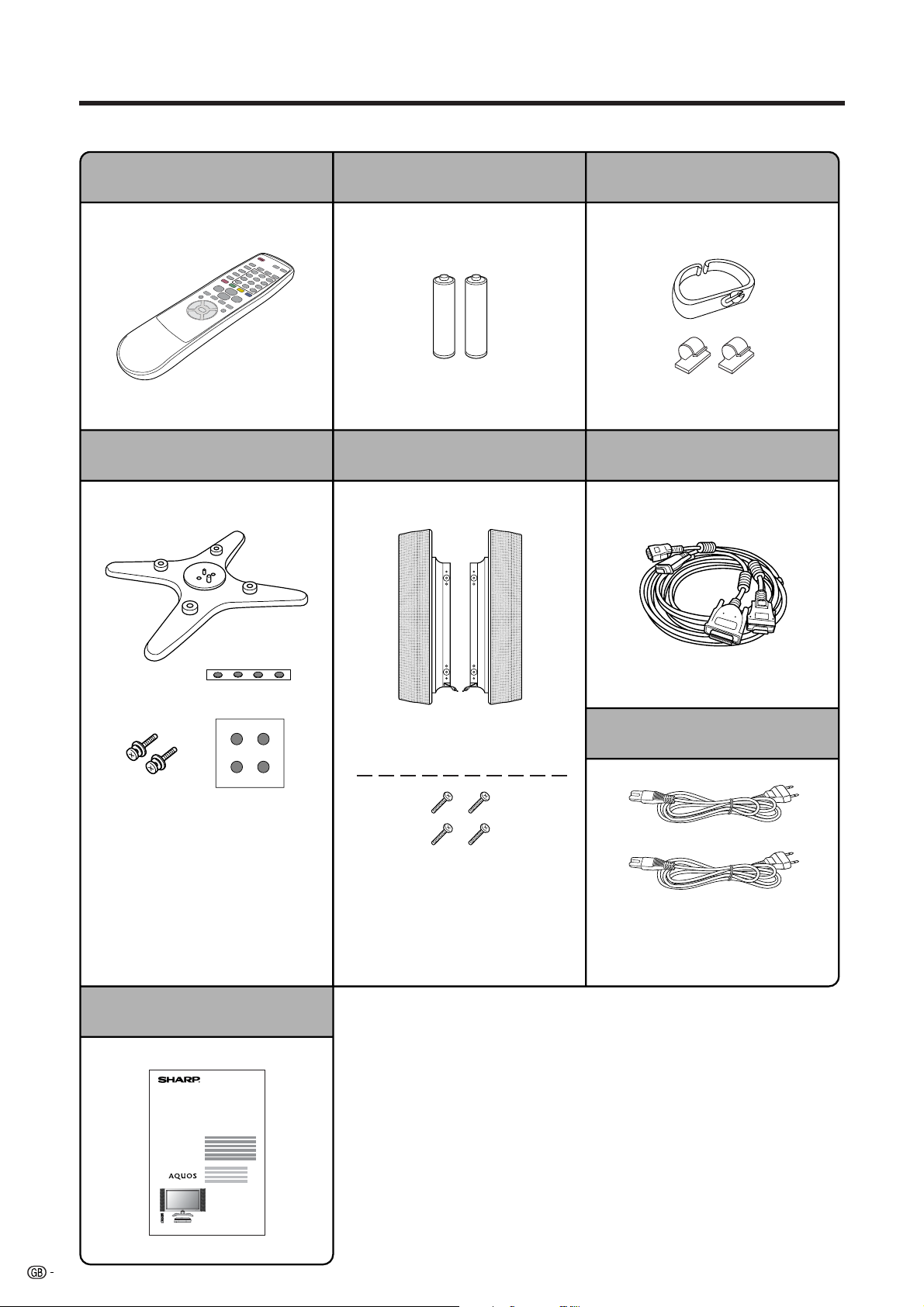
Supplied accessories
Make sure the following accessories are provided with the product.
Remote control unit (g1)
Page 10 Page 10 Page 8
Stand unit (for AVC System) (g1) System cable (g1)
LR6 (“AA” size) Alkaline battery (g2)
Speaker unit (g1)
Cable clamp (Large g1, Small g2)
Stand (g1)
Stand cushion (g4)
Stand spacer (g4)
Stand screw (g2)
Page 9
Operation manual
LC-37HV4E
Speaker (Lg1, Rg1)
Speaker screw (g4)
Page 5
Page 7
AC cord (g2)
Product shape varies in some
countries.
Page 7
4
Page 7
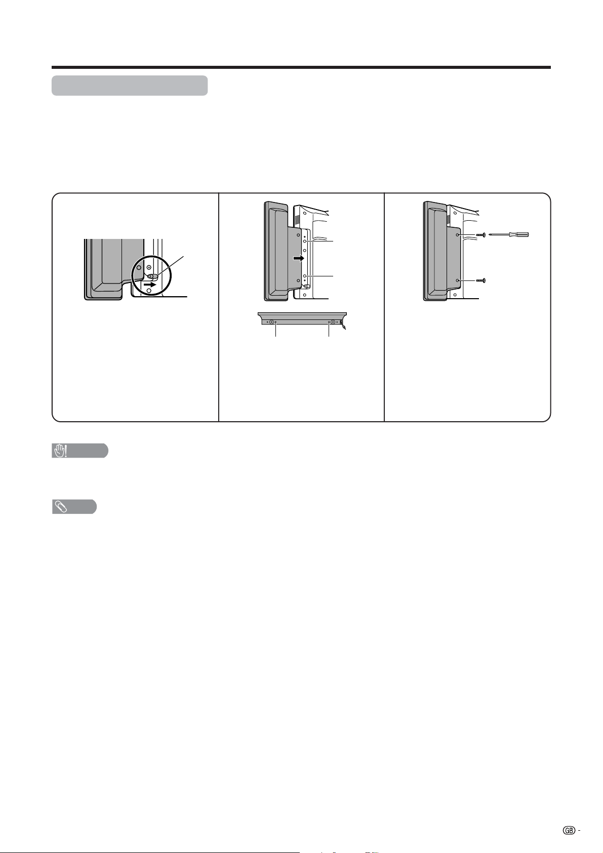
Preparation
Attaching the speakers
The supplied speaker unit can be attached to or detached from the Display. It must be attached unless you use
external amplifier/speakers.
Before attaching (or detaching) speakers, unplug the AC cord from the AC outlet.
Be sure to attach or detach the speakers with two or more people.
Example: Attaching right speaker.
123
Speaker
plug
Insert the speaker plug into the
terminal on the Display.
• Make sure that the speaker plug
is inserted completely.
CAUTION
• The speaker terminals on the Display are only for the supplied speaker unit. Do not connect any third party plug to the
terminal or speaker to the Display.
• Do not handle or move the Display by the speakers.
NOTE
• Perform the same steps for both left and right speakers.
• To detach the speakers, perform the above steps in reverse order.
• You can connect your own amplifier/speakers to the Display. See page 47 for connecting external speakers.
Take hold of the speaker and
slowly slide it to the Display.
• Make sure that the two bulges of
the speaker align with the holes
on the Display.
Hole
Hole
BulgeBulge
Fasten the screws to secure the
speaker in place.
• Use a screwdriver.
• Perform the same steps for
attaching left speaker.
5
Page 8
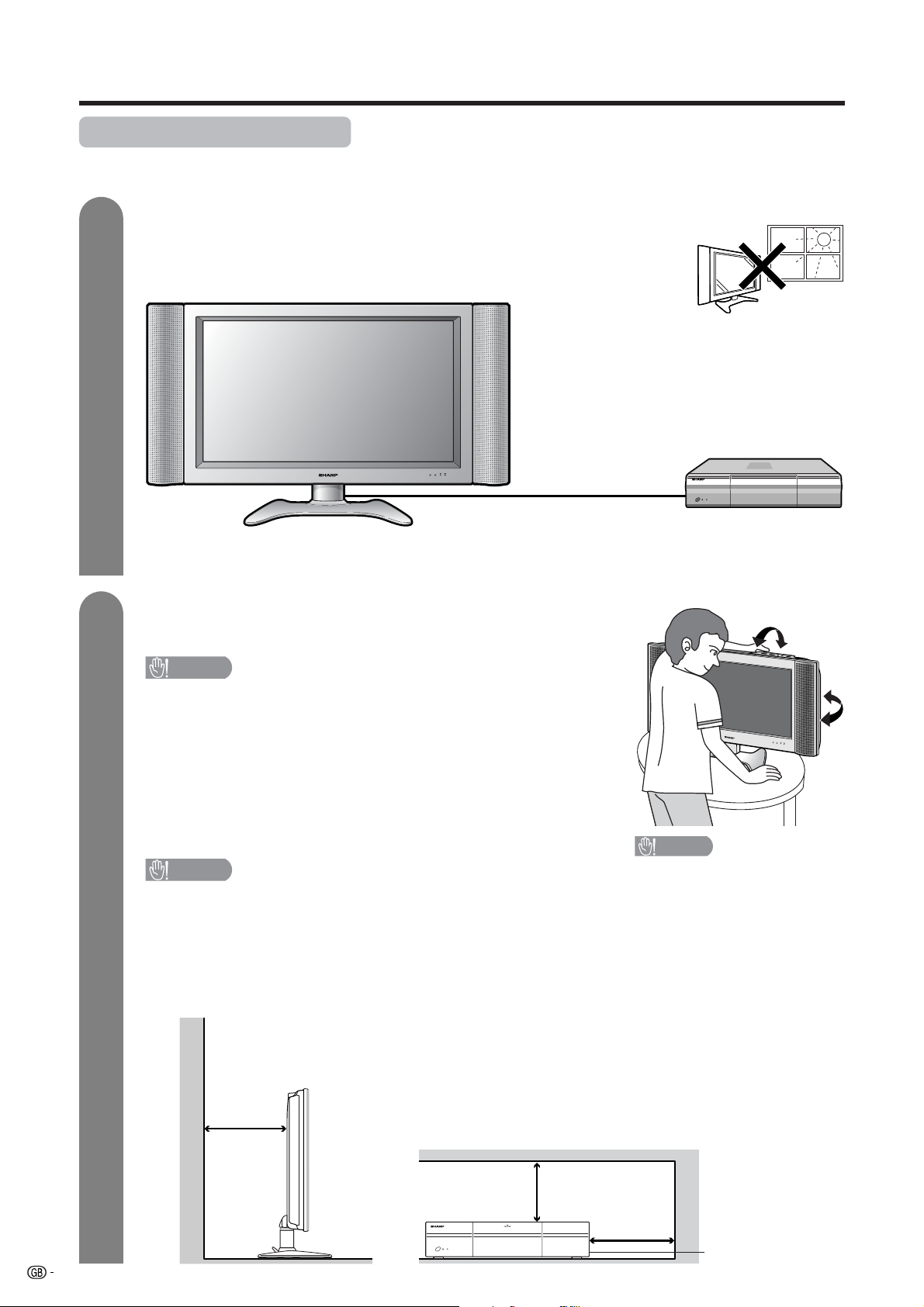
Preparation
Where to place the System
“System” means the Display and AVC System. First select the location where to place the System.
1
2
Selecting the location of the System
• Select a place with no direct sunlight and good ventilation.
• The Display and the AVC System are connected by the system cable.
(See page 7 for details.)
System cable
If you want to keep a longer distance between the
Display
Display and AVC System, please purchase the
optional system cable AN-07SC1 (about 7 meters).
(See page 72.)
Setting the System in place
Handling the Display
CAUTION
• The Display is very heavy. Move it with two or more people.
• Do not remove the stand from the Display unless using an
optional bracket to mount it.
• When moving, put your hands on the Display, but never on the
Display speakers.
• Keep enough space above and behind the Display.
AVC System
Handling the AVC System
CAUTION
• Do not put a VCR or other device on the AVC System.
• Keep enough space above and on the sides of the AVC System.
• Do not block the ventilation openings on the top and left side,
and the exhaust fan on the right side.
• Do not spread a thick cloth beneath the AVC System, or cover it
with one, as this can cause overheating and result in malfunction.
CAUTION
Adjust the screen with both
hands. Put one hand on the
Display and tilt the screen
while steadying the stand
with your other hand.
You can adjust the screen
vertically up to 4 degrees
forward or 6 degrees backward, or rotate 10 degrees
horizontally.
10 cm
or more
Keep enough space
5 cm or more
5 cm or more
on both sides
There is an exhaust fan
6
on the right side.
Page 9
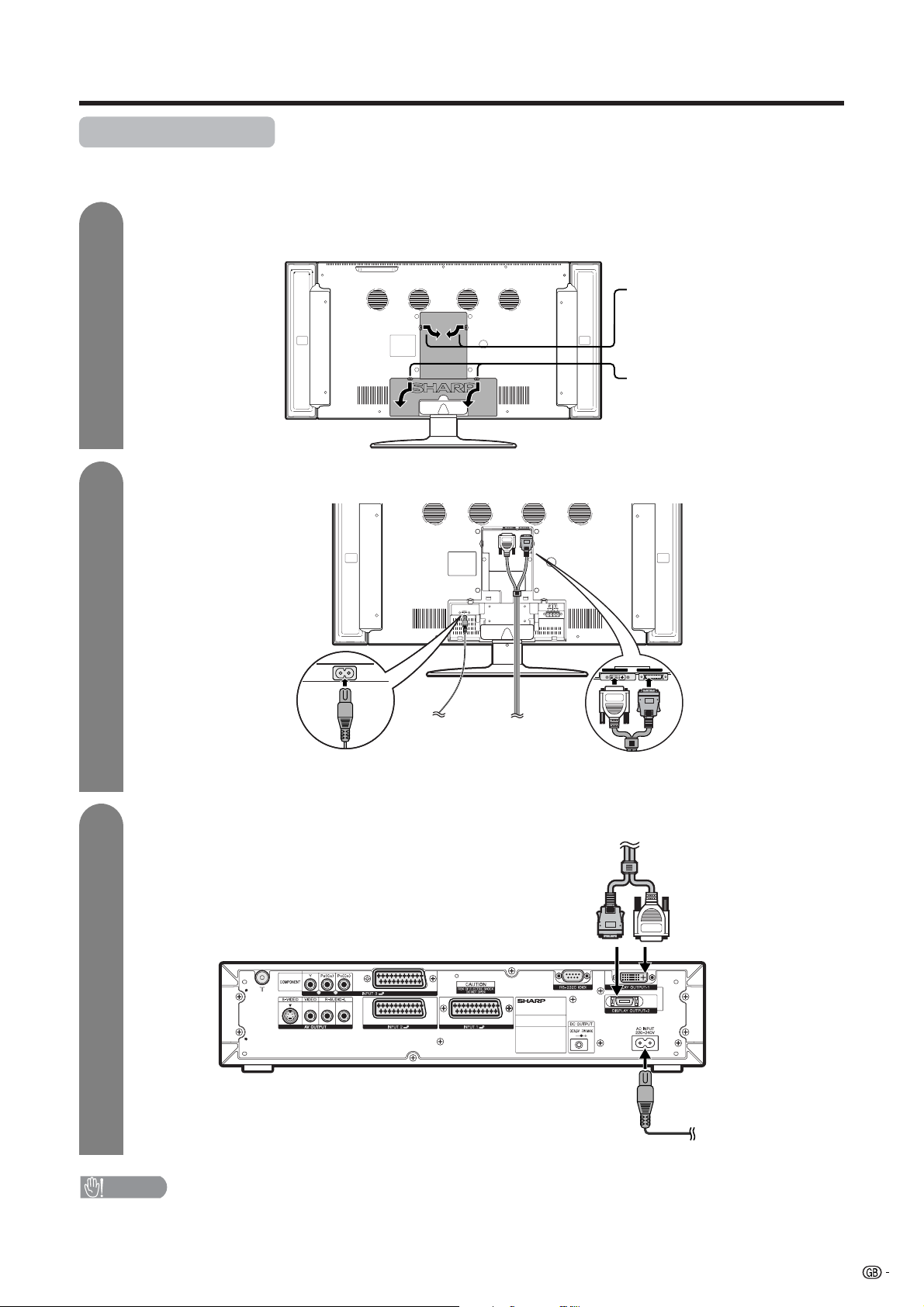
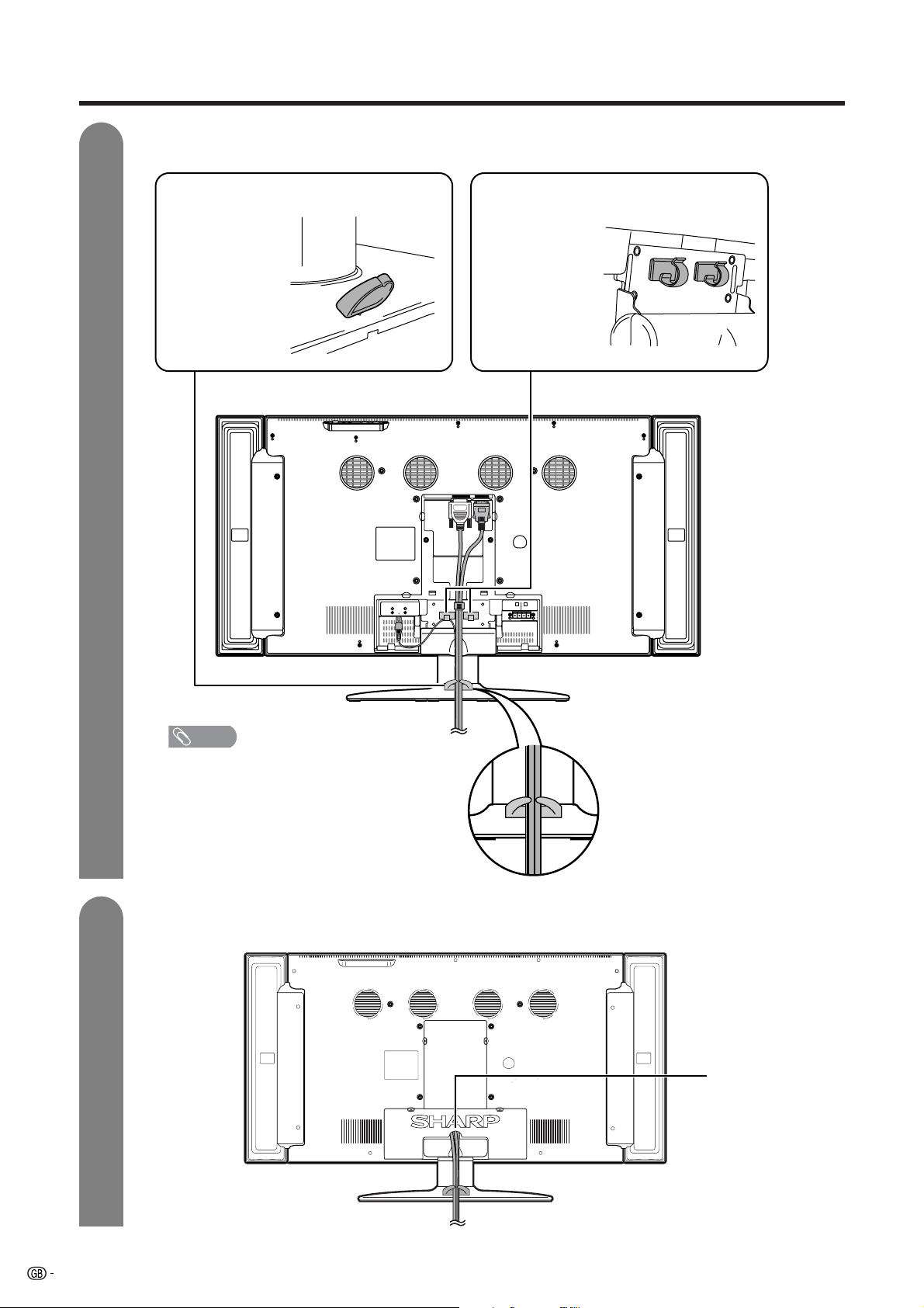
Preparation
Setting the System
After putting the Display and the AVC System in place, connect the system cables and AC cords. Use the
cable clamps for bundling the cables.
1
2
Removing the terminal cover
Display (rear view)
Connecting the system cable and the AC cord to the Display
AC INPUT
110V–240V
DISPLAY INPUT1 DISPLAY INPUT2
Press the two hooks
toward the centre of the
Display and remove the
cover toward you.
Press down the two
upper hooks to remove
the cover toward you.
3
Connect the plug into
AC cord System cable
the terminal and secure
it by tightening the
(WHITE)
thumb screws.
Connecting the system cable and the AC cord to the AVC System
System cable
(GREY) (WHITE)
AVC System (rear view)
AC cord
(GREY)
Connect the plug firmly
until the hooks on both
sides click.
CAUTION
• TO PREVENT RISK OF ELECTRIC SHOCK, DO NOT TOUCH UN-INSULATED PARTS OF ANY CABLES WITH THE
AC CORD CONNECTED.
7
Page 10
Preparation
4
Attaching the clamps and bundling the cables with the clamp
Cable clamp (Large)
Insert the cable
clamp in the hole
on the Display leg
as shown.
Cable clamp (Small)
Peel off the seal
on the back and
attach as shown.
Display (rear view)
5
NOTE
• The small clamp on the right is used for
bundling external speakers. (See page 47.)
Closing the terminal cover
Cables come out
from the small
opening.
8
Page 11
Preparation
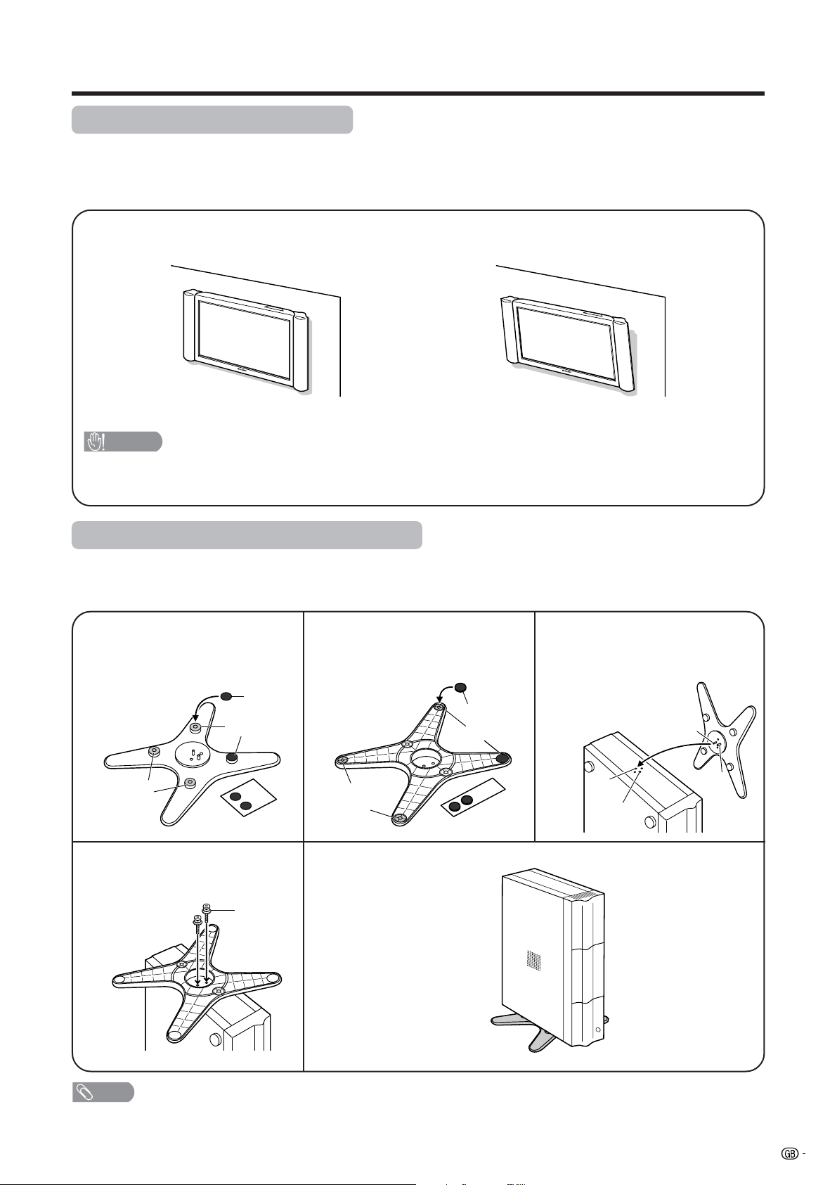
Setting the Display on the wall
Using an optional bracket to mount the Display
• You can ask a qualified service personnel about using an optional AN-37AG1 bracket to mount the Display
to the wall.
• Carefully read the instructions that come with the bracket before beginning work.
Hanging on the wall
AN-37AG1 wall mount bracket. (See the bracket instructions for details.)
Vertical mounting Angular mounting
CAUTION
• Installing the LCD Colour TV requires special skill that should only be performed by qualified service personnel.
Customers should not attempt to do the work themselves. SHARP bears no responsibility for improper mounting or
mounting that results in accident or injury.
Setting the AVC System with the stand
How to install the AVC System vertically using the stand unit.
• Use the supplied stand unit for installing the AVC System vertically in an upright position.
Stick each spacer to the
stand as shown.
1
Peel each spacer
away from the
paper and attach
to the four bulging
areas on the stand.
Bulge
Attach the stand using the
stand screws as shown.
4
Stand
spacer
Bulge
Stand screw
Attach each cushion to
the stand as shown.
2
Peel each cushion
away from the
paper and attach
to the four areas at
the bottom.
Attaching point
Stand cushion
Attaching point
The AVC System installed
vertically with the stand.
Fit the stand to the AVC
System.
3
Insert the stand into the AVC
System, making sure that the
thick and thin bulges of the
stand align with the big and
small holes on the AVC
System.
Small
hole
Big hole
Thin bulge
Thick
bulge
NOTE
• When mounting the AVC System vertically, always use the supplied stand. Be careful not to block vent holes when
standing up directly on the floor or a flat surface as this can result in equipment failure.
9
Page 12
Preparation
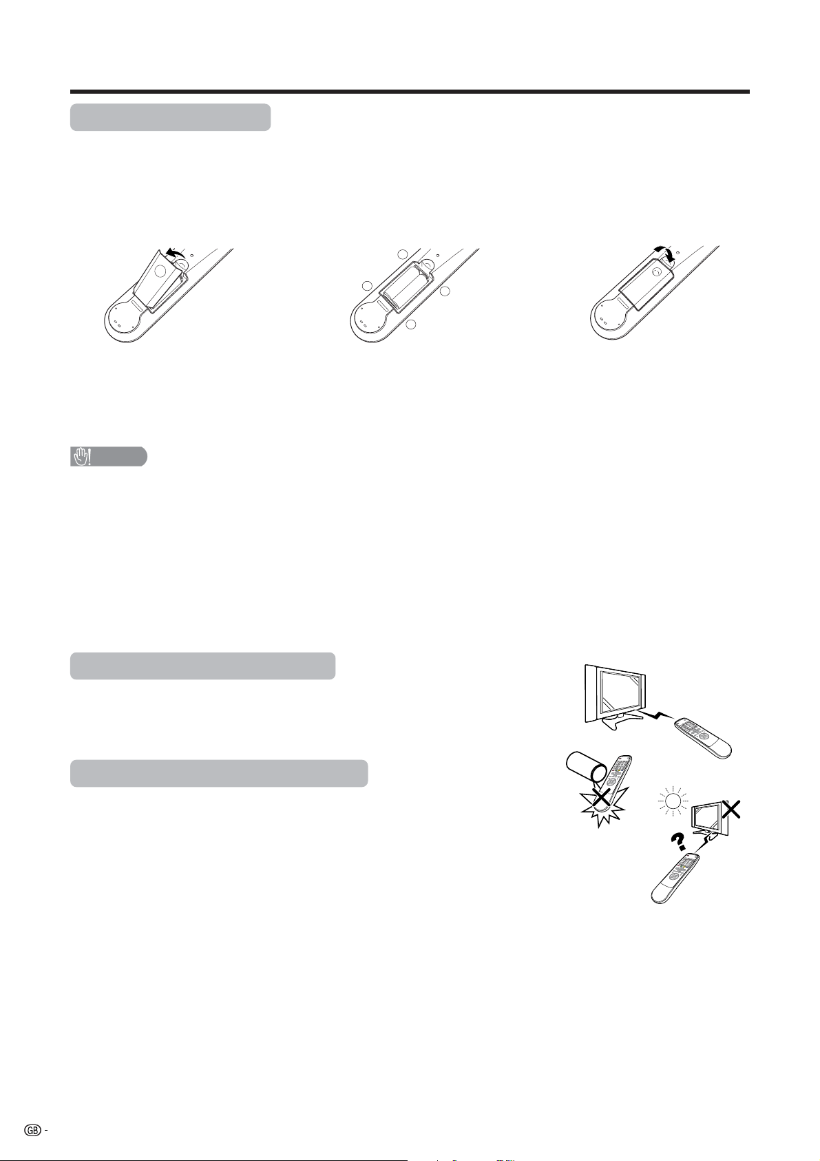
Inserting the batteries
Before using the System for the first time, insert two LR6 (“AA” size) Alkaline batteries (supplied). When the
batteries become depleted and the remote control fails to operate, replace the batteries with new LR6 (“AA”
size) Alkaline batteries.
1 Open the battery cover. 2 Insert two supplied LR6 (“AA” size)
Alkaline batteries.
+
_
• Place batteries with their terminals
corresponding to the (e) and (f)
indications in the battery compartment.
CAUTION
Improper use of batteries can result in chemical leakage or explosion. Be sure to follow the instructions below.
• Do not use manganese batteries. When you replace the batteries, use alkaline ones.
• Place the batteries with their terminals corresponding to the (e) and (f) indications.
• Do not mix batteries of different types. Different types of batteries have different characteristics.
• Do not mix old and new batteries. Mixing old and new batteries can shorten the life of new batteries or cause
chemical leakage in old batteries.
• Remove batteries as soon as they have worn out. Chemicals that leak from batteries can cause a rash. If you
find any chemical leakage, wipe thoroughly with a cloth.
• The batteries supplied with this product may have a shorter life expectancy due to storage conditions.
• If you will not be using the remote control unit for an extended period of time, remove the batteries from it.
_
+
3 Close the battery cover.
Using the remote control unit
Use the remote control unit by pointing it towards the remote sensor window.
Objects between the remote control unit and sensor window may prevent proper
operation.
Cautions regarding remote control unit
• Do not expose the remote control unit to shock.
In addition, do not expose the remote control unit to liquids, and do not place
in an area with high humidity.
• Do not install or place the remote control unit under direct sunlight.
The heat may cause deformation of the unit.
• The remote control unit may not work properly if the remote sensor window of
the Display is under direct sunlight or strong lighting. In such case, change
the angle of the lighting or Display, or operate the remote control unit closer to
the remote sensor window.
10
Page 13
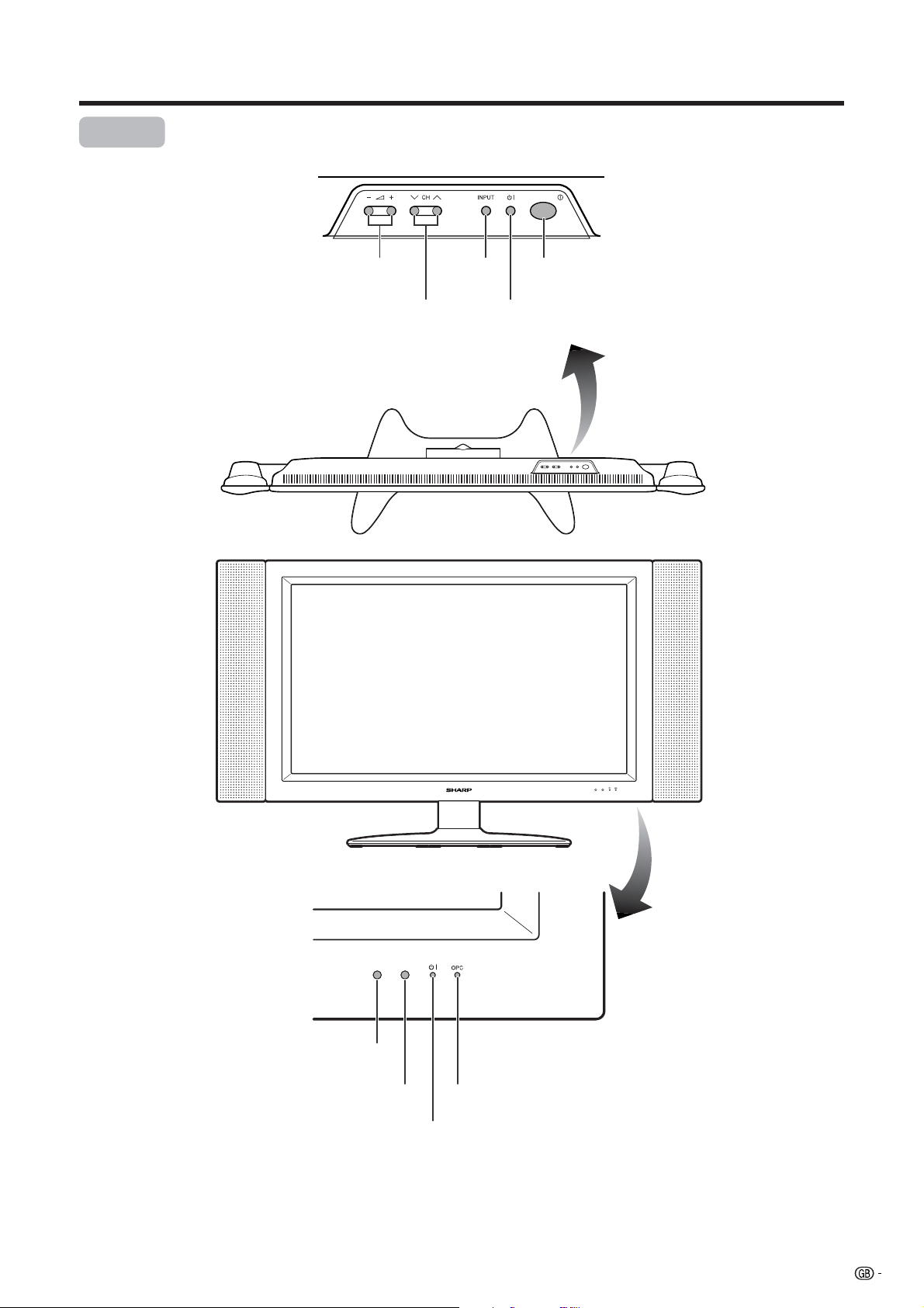
Part names
Display
VOLUME buttons
( il/k )
CHANNEL buttons
(CHs/r)
INPUT
button
STANDBY/ON button
(B)
MAIN POWER
button
Remote control sensor
OPC sensor
STANDBY/ON indicator
OPC indicator*
*OPC: Optical Picture Control
(See Pages 37 and 39.)
11
Page 14
Part names
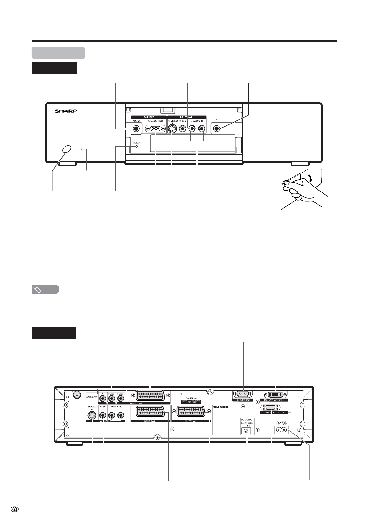
AVC System
Front view
PC INPUT terminal (AUDIO)
INPUT 4 terminal (VIDEO)
Headphone
(When connecting headphones,
the sound from the speakers is
muted.)
STANDBY/ON indicator
POWER button
PC INPUT terminal
(ANALOG RGB)
CLEAR*
INPUT 4 terminals (AUDIO)
INPUT 4 terminal (S-VIDEO)
(How to open the door)
* If the AVC System is switched on but it does not appear to be operating correctly, it may need resetting. In this
case, press CLEAR, shown in the diagram, lightly with the end of a ballpoint pen or other pointed object.
This will reset the System as shown below.
• AV MODE resets to USER.
• TV channel resets to channel 1.
• Dual screen resets to normal.
• Audio setting initialises.
• SRS resets to OFF.
• Image position is initialised.
NOTE
• Pressing CLEAR will not work if the System is in standby mode (indicator lights red).
• Pressing CLEAR will not delete channel preset or password. See page 61 for clearing the password when you know it.
See page 75 for initialising to the factory preset values when you forget your password.
Rear view
INPUT 3 terminals (Y, P
B(CB), PR(CR))
RS-232C terminal
ANTENNA INPUT terminal
AV OUTPUT terminal
(S-VIDEO)
12
INPUT 3 terminal (SCART)
AV OUTPUT terminals
(AUDIO)
AV OUTPUT terminal
(VIDEO)
INPUT 1 terminal
(SCART)
INPUT 2 terminal (SCART)
DISPLAY OUTPUT1 terminal
DISPLAY OUTPUT2
terminal
DC OUTPUT terminal
(Terminal for expanded
functionality in the near
future.)
AC INPUT terminal
Page 15
Part names
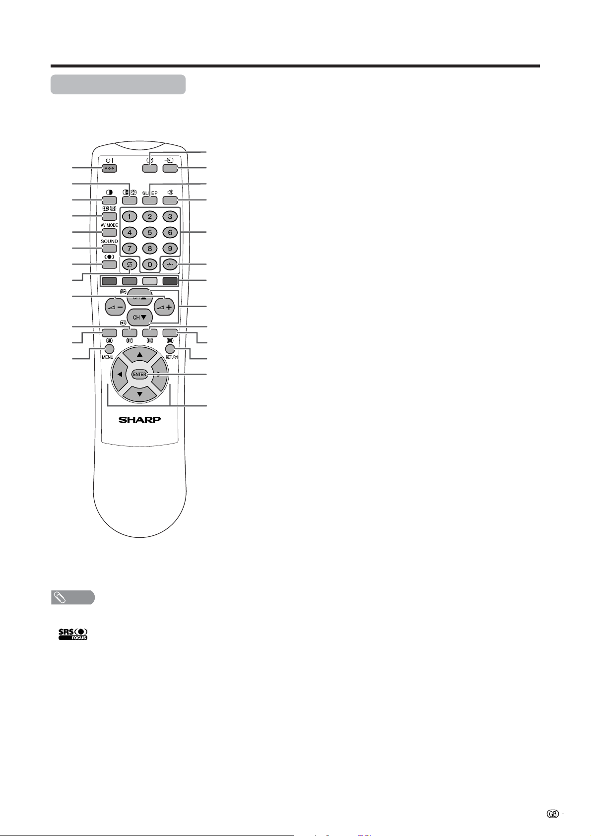
Remote control unit
13
1
2
3
14
15
16
4
5
17
6
7
8
18
19
9
20
10
11
12
21
22
23
24
25
NOTE
• When using the remote control unit, point it
at the Display.
*
is a trademark of SRS Labs, Inc.
FOCUS technology is incorporated under
license from SRS Labs, Inc.
1 B (STANDBY/ON)
To switch the power on and off. (See page 15.)
2 du (FREEZE/HOLD for TELETEXT)
TV/External input mode: Change the still image mode.
TELETEXT mode: Freeze a multi-page on screen while other
pages are automatically updated. Press d again to return to the
normal image. (See pages 63 and 64.)
3 c (DUAL screen)
Set the dual picture mode. Press c again to return to normal view.
(See page 62.)
4 fv (WIDE MODE/ T/B/F)
TV/External input mode: Change the wide image mode. (See pages
54 and 55.)
TELETEXT mode: Set the area of magnification. (full/upper half/
lower half) (See page 64.)
5 AV MODE
Select a video setting: AV MODE (STANDARD, DYNAMIC, MOVIE,
GAME, USER), PC MODE (STANDARD, USER) (See page 53.)
6 SOUND
Select the sound multiplex mode. (See page 21.)
7 h (SRS and FOCUS)*
Select SRS and FOCUS sound system. (See page 20.)
8 A (Flashback)
Press to return to the previous channel in normal viewing mode.
Press to return to the previous page in TELETEXT mode. (See page
18.)
9 il/ik (VOLUME)
Set the volume. (See page 19.)
10 k (Reveal hidden for TELETEXT)
TELETEXT mode: Display hidden characters. (See page 64.)
11 j (SUBPAGE for TELETEXT)
TELETEXT mode: Change the picture mode for sub-page selecting.
(See page 65.)
12 MENU
Display the MENU screen.
13 C (CHANNEL INFORMATION)
Display the channel information and time. (See page 66 for details
on the time display.)
14 b (INPUT SOURCE)
Select an input source. (TV, INPUT 1, INPUT 2, INPUT 3, INPUT 4,
PC) (See pages 41, 42, 44-46 and 52.)
15 SLEEP
Set the Sleep timer. (See page 59.)
16 e (MUTE)
Mute the sound. (See page 19.)
17 0 – 9
TV/External input mode: Set the channel.
TELETEXT mode: Set the page.
18 o (Digit for channel select)
Change the digits of the selected TV channel. (See page 18.)
19 Colour (RED/GREEN/YELLOW/BLUE)
TELETEXT mode: Select a page. (See page 64.)
20 CHa/CHb(w/x )
TV/External input mode: Select the channel.
TELETEXT mode: Set the page. (See page 64.)
21 l (TOP Overview for TELETEXT)
TELETEXT mode: Display an index page for CEEFAX/FLOF
information. TOP Overview for TOP programme. (See page 65.)
22 m (TELETEXT)
Select the TELETEXT mode. (all TV image, all TEXT image, TV/TEXT
image) (See pages 64 and 65.)
23 RETURN
MENU mode: Return to the previous menu screen.
24 ENTER
Execute a command.
Return to the initial image position after moving with a/b/c/d.
25 a/b/c/d (Cursor)
Select a desired item on the setting screen.
Move the picture on the screen.
13
Page 16
Watching TV
Simple operations for watching a TV programme
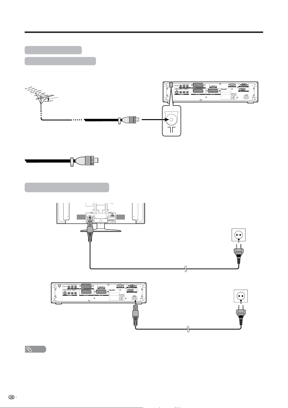
Basic connection
Connecting to an antenna
To enjoy a clearer picture, use an outdoor antenna. The following is a brief explanation of the types of connections
that are used for coaxial cable.
Standard DIN45325 plug (IEC169-2)
75-ohm coaxial cable (round cable)
(commercially available)
Antenna cables–commercially available
If your outdoor antenna uses a 75-ohm coaxial cable with a standard DIN45325
plug (IEC 169-2), plug it into the ANTENNA INPUT terminal at the rear of the
AVC System.
Connecting to the power outlet
Display (rear view)
AVC System (rear view)
Product shape varies
in some countries.
Product shape varies
in some countries.
NOTE
• Always turn off the main power of Display and AVC System when connecting the AC cords.
• Disconnect the AC cords from the AC outlet, Display and AVC System if the System will not be used for a long period of
time.
14
Page 17

Watching TV
Display
STANDBY/ON button
STANDBY/ON indicator
AVC System
STANDBY/ON indicator
POWER
MAIN POWER
Turning on the power
1
2
When turning the AVC System on first
1
2
• The initial auto installation starts when the System powers on for the first
time. If the System has been turned on before, the initial auto installation
will not be invoked. See page 23 to try auto installation from the Setup
menu.
Press MAIN POWER on the Display.
• The STANDBY/ON indicator on the Display flashes red.
Press POWER on the AVC System.
• The System turns the power on.
• The STANDBY/ON indicator on the Display lights up
green and the one on the AVC System lights up green.
• If the STANDBY/ON indicators still light up red, press
B on the remote control unit or STANDBY/ON button
on the Display to turn the System on.
Press POWER on the AVC System.
• The STANDBY/ON indicator on the AVC System lights
up red.
Press MAIN POWER on the Display.
• The System turns the power on.
• The STANDBY/ON indicator on the Display lights up
green and the one on the AVC System lights up green.
• If the STANDBY/ON indicators still light up red, press
B on the remote control unit or STANDBY/ON button
on the Display to turn the System on.
NOTE
Display status indicator
Off
Flashing red
Red
Green
Power off
AVC System does not turn on or its AC cord is disconnected.
The System is in standby mode.
The System is on.
Turning off the power
1
2
3
• If you are not going to use this System for a long period of time, be sure to
remove the AC cords from the power outlet.
• Weak electric power is still consumed even when both MAIN POWER and
POWER are turned off.
• When the STANDBY/ON indicator lights up red, it takes about 10 to 15
seconds for the indicator to turn off if POWER on the AVC System is turned
“Off” or the AC cord is unplugged from the AC outlet.
Press B on the remote control unit or STANDBY/
ON button on the Display.
• The System enters standby mode and the image on the
screen disappears.
• Both STANDBY/ON indicators change from green to red.
Press POWER on the AVC System.
• The STANDBY/ON indicator on the AVC System turns
off and the one on the Display flashes red.
Press MAIN POWER on the Display.
• The STANDBY/ON indicator on the Display gradually
turns off.
NOTE
AVC System status indicator
Off
Red
Green
Power off
Only the AVC System is in standby mode or the System is in standby mode.
The System is on.
15
Page 18

Watching TV
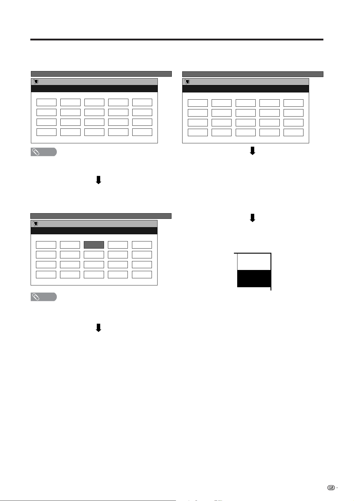
Initial auto installation
When the System powers on for the first time after
purchase, the initial auto installation is invoked. You
can automatically set language, country and channels
in successive operations.
NOTE
• The initial auto installation functions only once. If the initial
auto installation is not completed, you can perform it again.
See page 23 to try auto installation from the setup menu.
• The initial auto installation stops by pressing RETURN.
1
2
Setting the on-screen display language
1 Press a/b/c/d to select the desired
language listed on the screen.
2 Press ENTER to enter the setting.
TV MENU
Setup
Auto Installation - Language
English Deutsch Français
Setting the country or area
1 Press a/b/c/d to select your country
or area listed on the screen.
2 Press ENTER to enter the setting.
• The programme auto search starts at the same
time.
TV MENU
Setup
Auto Installation - Country
Austria Belgium
Denmark Finland
After this setting, auto search starts with the following
order.
1 Programme auto search
2 Auto labelling
3 Auto sorting
4 Preset download
You do not need to do anything during the auto search.
(Go to the next page.)
NOTE
• The illustrations and on-screen displays in this manual
are for explanation purposes and may vary slightly from
the actual operations.
16
Page 19
Watching TV
Automatic channel searching
Channel auto search finds all channels viewable in
your area.
TV MENU
Setup
Auto Installation Programme Setup “Auto”
01 55.25 02 85.25 03 102.25
NOTE
• If no channel is found, “No programme found. Is antenna
connected properly?” displays. And the auto installation
finishes.
Automatic channel labelling
After finding TV channels, the System starts naming
each TV channel found.
TV MENU
Setup
Auto Installation Programme Setup “Auto”
01 SAT.1 02 PR07 03 KABEL
Automatic channel sorting
When channel auto labelling finishes, the System starts
sorting the labelled channels.
TV MENU
Setup
Auto Installation Programme Setup “Auto”
01 SAT.1 02 PR07 03 KABEL
Preset download
When auto sorting finishes, the System automatically
downloads and stores each sorted channel.
• When a VCR is connected via INPUT 2, the System sends
all preset channel information to the VCR. (See pages 42
and 43.)
• “Auto Installation completed.” displays. After that, the
screen changes to the auto installation menu.
Watching TV
The setup menu disappears and you can watch the
programme on channel 1.
NOTE
• The System can only name channels where the channel
labelling information is provided. If channel information is
not provided, the System displays “-----”.
SAT.1
1
PAL
B/G
17
Page 20
Watching TV
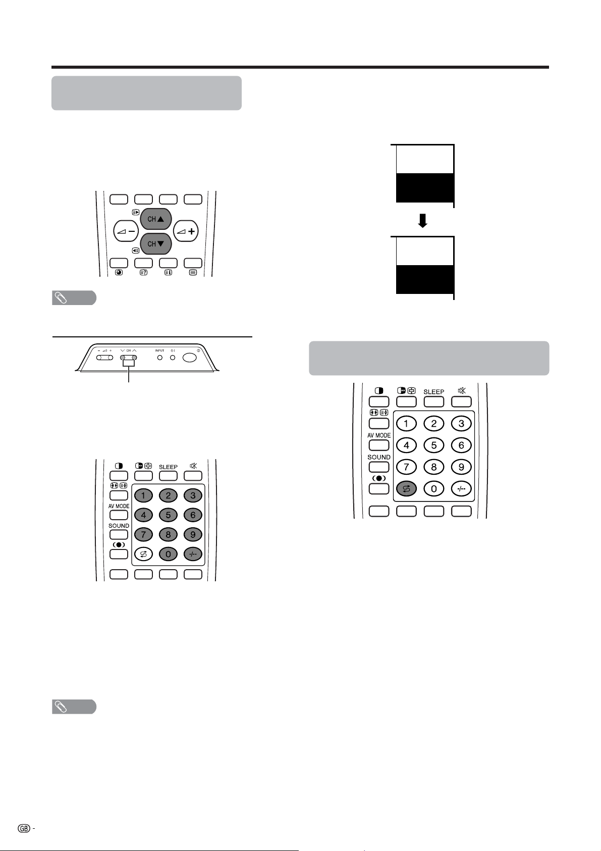
Simple button operations for
changing channels
You can change channels in several ways.
aa
Using CH
• Press CH
• Press CH
NOTE
• CHs/r on the Display operates the same as CH
the remote control unit.
bb
a/
bon the remote control unit
aa
bb
aa
a to increase channel number.
aa
bb
b to decrease channel number.
bb
bb
b/
bb
aa
aon
aa
Channel display
Channel display changes approximately after 3
seconds as shown below.
SAT.1
12
PAL
B/G
(Example)
SAT.1
12
MONO
Using Flashback (A) on the remote
control unit
CHs/r
Using 0 – 9 on the remote control unit
Select the channels directly by pressing buttons 0 to
9.
a
To select a 1-digit channel (e.g. channel 2):
• Press 2.If
change, press o to switch over to the 1-digit select
mode and press 2 again.
To select a 2-digit channel (e.g. channel 12):
• Press o to set the 2-digit select mode. Press 1,
followed by 2.
“2” is indicated and the picture does not
Press A to switch the currently tuned channel to the
previously tuned channel.
Press A again to switch back to the currently tuned
channel.
NOTE
• Complete this procedure within 3 seconds, otherwise the
selection will not be made on the 2-digit channel mode.
When viewing Teletext information
View a page directly which is 3-digit page number from
100 to 899 by pressing buttons 0 to 9. With Teletext,
you do not use o. (See page 65).
18
Page 21
Watching TV
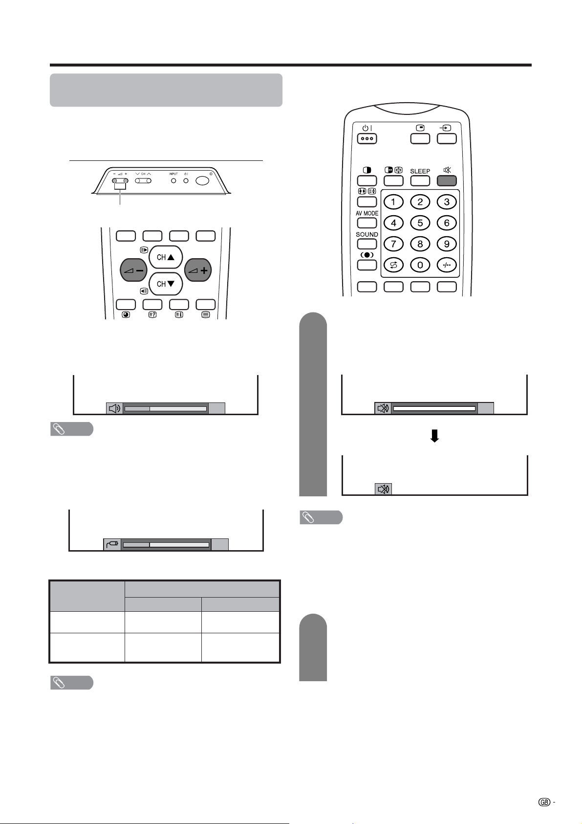
Simple button operation for changing
volume/sound
Changing the volume
You can change the volume on the Display or on the
remote control unit.
ll
l/
ll
kk
k
kk
kk
k.
kk
ll
l.
ll
i
• To increase the volume, press i
• To decrease the volume, press i
Using e on the remote control unit
e mutes the current sound output.
1
Press e.
•“e” has been displayed on the screen for 30
minutes, and the sound is silenced.
20
NOTE
• “TV”, “INPUT1”, “INPUT2”, “INPUT3”, “INPUT4” and “PC”
modes can each store volume adjustment values
separately.
When “Audio Out” is set to “Variable”, the indicator on
the screen changes as shown below.
20
Audio status
Output device
Speaker
AV OUTPUT
NOTE
• See page 59 for details on the audio out function.
Variable sound
Constant as
specified
Audio out
VariableFixed
Mute
Variable sound
Mute
0
NOTE
• Within 30 minutes of pressing e, mute can be canceled
by using one of the two methods below.
• Pressing i
A can also cancel the mute.
• Changing channels can also cancel the mute.
• Mute will be canceled after 30 minutes have elapsed.
However, the System will not suddenly output a loud
sound as the volume level is set to 0 automatically.
2
ff
f/i
ff
ee
e, SOUND, CH
ee
aa
bb
a/CH
b, 0 – 9, b or
aa
bb
Within 30 minutes, Press e again to cancel
the mute.
• Before 30 minutes, the volume level returns to
the previous setting.
• After 30 minutes, increase the volume level by
pressing ie.
19
Page 22
Watching TV
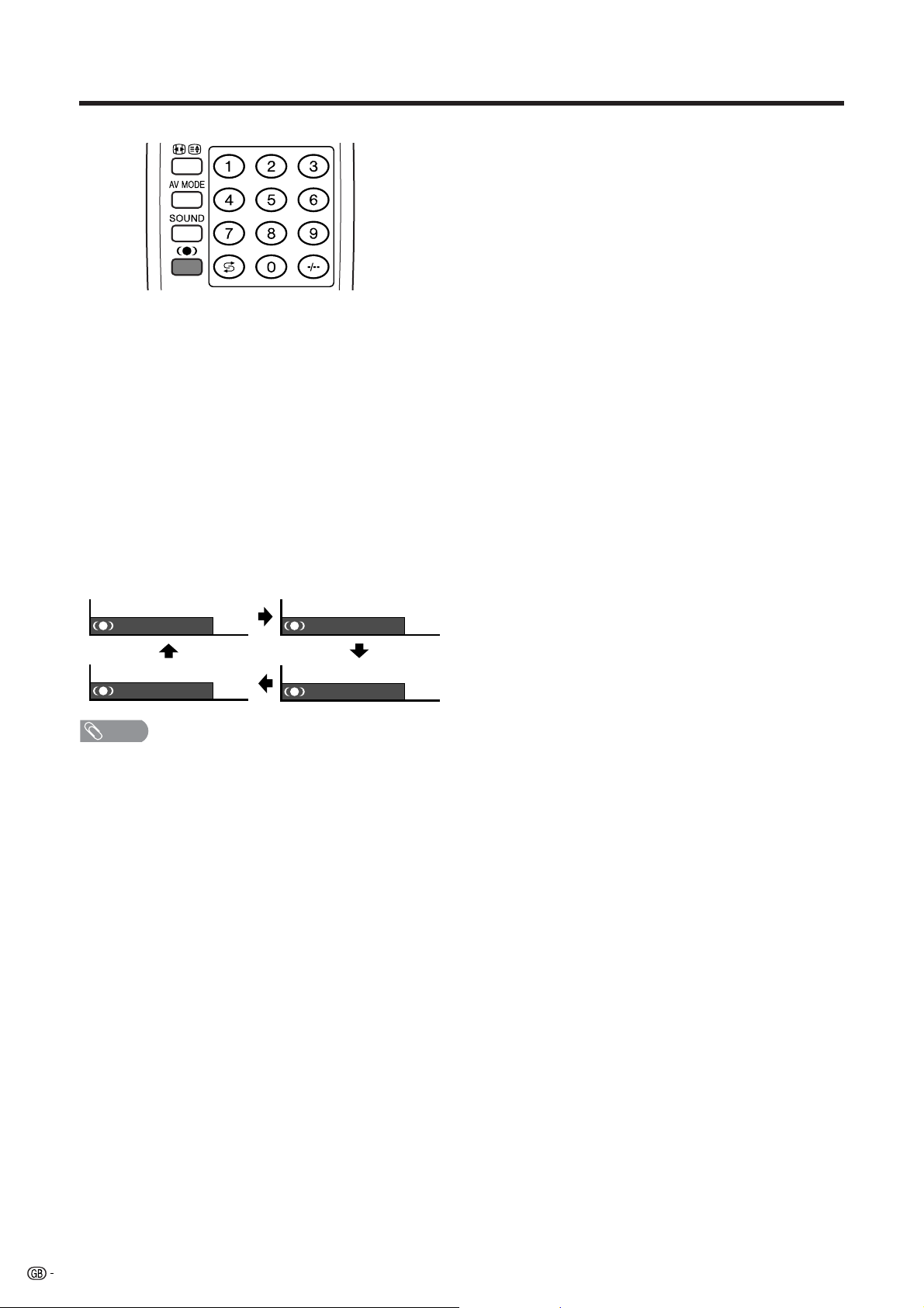
Using h on the remote control unit
h produces SRS and FOCUS effect from the
speakers.
Each time you press h, the mode changes among
SRS, FOCUS, FOCUSeSRS and OFF.
SRS sound options
• SRS (Sound Retrieval System): Creates more a
natural sound retrieving the spatial information from
any stereo recording and restoring the original threedimensional sound field.
• FOCUS: Repositions a sound image from two
speakers to a more optimal listening position or
height without moving them.
• FOCUSeSRS: Produces both SRS and FOCUS
effects.
• OFF: Outputs the normal sound.
: OFF
: FOCUS+SRS
NOTE
• You can have the same settings by choosing “Surround”
on the menu items. (See page 36.)
: SRS
: FOCUS
20
Page 23
Watching TV
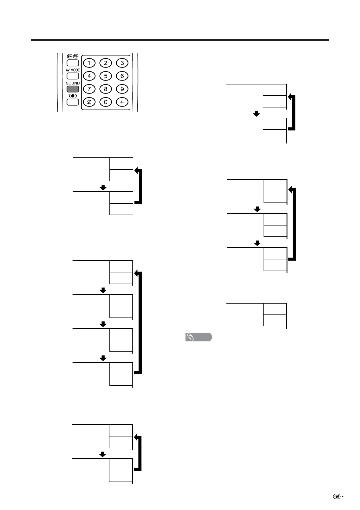
Using SOUND on the remote control unit
In the NICAM TV broadcasts
When receiving a stereo signal
Each time you press SOUND, the mode switches
between NICAM STEREO and MONO.
Stereo mode
BBC2
99
NICAM
STEREO
BBC2
99
MONO
When receiving a bilingual signal
Each time you press SOUND, the mode switches
among NICAM CH A, NICAM CH B, NICAM CH AB
and MONO.
Bilingual mode
BBC2
99
NICAM
CH A
BBC2
99
NICAM
CH B
BBC2
99
NICAM
CH AB
BBC2
99
In the TV mode of IGR TV broadcasts
When receiving a stereo signal
Each time you press SOUND, the mode switches
between STEREO and MONO.
Stereo mode
BBC2
99
STEREO
BBC2
99
MONO
When receiving a bilingual signal
Each time you press SOUND, the mode switches
among CH A, CH B and CH AB.
Bilingual mode
BBC2
99
CH A
BBC2
99
CH B
BBC2
99
CH AB
When receiving a monaural signal
When you press SOUND, “MONO” displays.
Monaural mode
BBC2
99
MONO
NOTE
• When no signal is input, the sound mode will display
“MONO”.
• “BBC2” and “99” are tentative network name and channel.
MONO
When receiving a monaural signal
Each time you press SOUND, the mode switches
between NICAM MONO and MONO.
Monaural mode
BBC2
99
NICAM
MONO
BBC2
99
MONO
21
Page 24
Basic adjustment settings
AV input mode menu items
List of AV menu items to help you with
operations
Picture
Contrast ......................................... Page 31
Brightness ..................................... Page 31
Colour ............................................ Page 31
Tint ................................................. Page 31
Sharpness...................................... Page 31
Advanced
C.M.S. ................................... Page 32
Colour Temp ........................ Page 33
Black .................................... Page 33
Monochrome ....................... Page 34
Film Mode ............................ Page 34
I/P Setting ............................ Page 35
DNR ...................................... Page 35
Audio
PC input mode menu items
List of PC menu items to help you with
operations
Picture
Contrast ......................................... Page 31
Brightness ..................................... Page 31
Red ................................................. Page 31
Green.............................................. Page 31
Blue ................................................ Page 31
C.M.S. ............................................. Page 32
Audio
Treble.............................................. Page 36
Bass ............................................... Page 36
Balance .......................................... Page 36
Surround ........................................ Page 36
Speaker .......................................... Page 48
Power control
Power Save .................................... Page 37
No Signal off .................................. Page 38
No Operation off ........................... Page 38
Setup
Auto Installation ............................ Page 23
Programme Setup .................. Pages 24-29
Child Lock...................................... Page 61
Position .......................................... Page 49
WSS ................................................ Page 57
4:3 Mode ........................................ Page 57
Rotate ............................................. Page 58
Language ....................................... Page 30
Treble.............................................. Page 36
Bass ............................................... Page 36
Balance .......................................... Page 36
Surround ........................................ Page 36
Speaker .......................................... Page 48
Power control
Power Save .................................... Page 39
Power Management ...................... Page 39
Setup
Input Signal ................................... Page 56
Auto Sync. ..................................... Page 51
Fine Sync. ...................................... Page 51
Rotate ............................................. Page 58
Language ....................................... Page 30
22
Option
Input Select.................................... Page 52
Audio Out....................................... Page 59
Cool Climate .................................. Page 60
Colour System............................... Page 53
Option
Audio Out....................................... Page 59
Cool Climate .................................. Page 60
Page 25

Basic adjustment settings
Auto installation
You can run auto installation again, even after setting
up the preset channels.
4
5
Press a/b to select “Auto Installation”, and
then press ENTER.
TV MENU
Setup Option
Auto Installation
Programme Setup
Child Lock
Position
WSS
4:3 Mode [Normal]
Rotate
Language
[Off]
[Normal]
[English]
Press c/d to select “Yes”, and then press
ENTER.
TV MENU
Setup
Auto Installation
NoYes
1
2
3
Press MENU and the TV MENU screen
displays.
Press c/d to select “Setup”.
If you already set the password for child lock,
go to step 3. If not, skip to step 4.
• See page 61 for setting password.
TV MENU
Setup Option
Password
Press a/b to select “Password”, and then
press ENTER.
Child Lock Password
––––
6
You can set language and country the same
as in the initial auto installation. Follow steps
1 and 2 on page 16. After this setting, auto
search starts with the following order.
1 Programme auto search
2 Auto labelling
3 Auto sorting
4 Preset download
You do not need to do anything during the
auto search.
Enter your 4-digit password with 0 - 9 on the
remote control unit.
23
Page 26

Basic adjustment settings
Programme setup
You can run the auto installation procedure again at
any time, by accessing the Setup menu, then
Programme Setup. Channels can be tuned
automatically or manually.
Auto search
You can also automatically search and download TV
channels by performing the procedure below. This is
the same function as from programme auto search to
preset download in auto installation on page 23.
1
Press MENU and the TV MENU screen
displays.
5
Press c/d to select “Yes”, and then press
ENTER.
• Auto search starts with the following order.
1 Programme auto search
2 Auto labelling
3 Auto sorting
4 Preset download
NOTE
• See page 17 for details.
2
3
4
Press c/d to select “Setup”.
• If password is already set, you are asked to
enter it. Follow the same steps as explained in
“Auto installation”. (See steps 2 and 3 on page
23.)
Press a/b to select “Programme Setup”,
and then press ENTER.
TV MENU
Setup Option
Auto Installation
Programme Setup
Child Lock
Position
WSS
4:3 Mode [Normal]
Rotate
Language
[Off]
[Normal]
[English]
Press a/b to select “Auto Search”, and then
press ENTER.
TV MENU
Setup
Programme Setup
Auto Search
Manual Adjust
Sort
24
Yes No
Page 27

Basic adjustment settings
Manual setting for each channel
You can set some channel items manually. They are
Fine (TV frequency), Colour sys., Sound sys., Label
(Network name), Skip, Decoder and Lock (Child Lock).
1
2
3
Press MENU and the TV MENU screen
displays.
Press c/d to select “Setup”.
• If password is already set, you are asked to
enter it. Follow the same steps as explained in
“Auto installation”. (See steps 2 and 3 on page
23.)
Press a/b to select “Programme Setup”,
and then press ENTER.
TV MENU
Setup Option
Auto Installation
Programme Setup
Child Lock
Position
WSS
4:3 Mode [Normal]
Rotate
Language
[Off]
[Normal]
[English]
Programme Setup “Manual” menu
TV MENU
Setup
Programme Setup “Manual”
01 SAT.1 02 PR07 03 KABEL
Next
NOTE
• When you exit Programme Setup “Manual” menu, preset
download automatically runs if you change information
on that menu.
You can select one of the following settings.
1 Fine (See page 26.)
2 Colour system (See page 27.)
3 Sound system (See page 27.)
4 Label (See page 27.)
5 Skip (See page 28.)
6 Decoder (See page 28.)
7 Lock (See page 28.)
4
5
Press a/b to select “Manual Adjust”, and
then press ENTER.
TV MENU
Setup
Programme Setup
Auto Search
Manual Adjust
Sort
Yes No
Press c/d to select “Yes”, and then press
ENTER.
25
Page 28
Basic adjustment settings
TV MENU
Setup
Programme Setup “Manual”
Fine
Colour sys.
Sound sys.
Label
Skip
Decoder
Lock
[179.25]
[AUTO]
[B/G]
[Off]
[SAT.1]
[Off]
[Off]
179.25
Manual setting for each channel (continued)
Fine tuning
1
2
3
Press a/b/c/d to select the channel you
want to edit, and then press ENTER.
• The selected channel information displays.
Press a/b to select “Fine”, and then press
ENTER.
Press c/d to adjust the frequency, and then
press ENTER.
• Adjust while checking the background picture
as a reference.
• Instead of the above, you can also set by
directly entering the frequency number of the
channel with 0 – 9.
a
• 179.25 MHz: Press 1 s 7 s 9 s 2 s 5 s
ENTER.
• 49.25 MHz: Press 4 s 9 s 2 s 5 s ENTER.
26
Page 29

Basic adjustment settings
Manual setting for each channel (continued)
Colour system
1
Press a/b/c/d to select the channel you
want to edit, and then press ENTER.
• The selected channel information displays.
2
Press a/b to select “Colour sys.”, and then
press ENTER.
• Receivable colour systems are listed.
Colour system menu
TV MENU
Setup
Programme Setup “Manual”
Fine
Colour sys.
Sound sys.
Label
Skip
Decoder
Lock
[179.25]
[AUTO]
[B/G]
[SAT.1]
[Off]
[Off]
[Off]
AUTO
PAL
SECAM
NTSC 4.43
PAL-60
3
Press a/b to select the optimum sound
system, and then press ENTER.
NOTE
• If you adjust this setting, please check the colour system
information. (See left column.)
Labelling channels
When a TV channel sends its Network Name, the auto
installation detects the information and assigns a name
to it. However, you can change individual channel
names.
1
Press a/b/c/d to select the channel you
want to edit, and then press ENTER.
• The selected channel information displays.
2
Press a/b to select “Label”, and then press
ENTER.
• Alphabets and numbers are listed.
Labelling menu
TV MENU
Setup
Programme Setup “Manual”
Fine
Colour sys.
Sound sys.
Label
Skip
Decoder
Lock
[179.25]
[AUTO]
[B/G]
[SAT.1]
[Off]
[Off]
[Off]
B
D
A
C
K
U
0123456789
E
M
O
L
N
W
Y
V
X
F
P
Z
H
G
R
Q
+
–_
I
S
.
J
T
CLEAR
BACK
END
3
Press a/b to select the optimum colour
system, and then press ENTER.
Sound system (Broadcasting system)
1
Press a/b/c/d to select the channel you
want to edit, and then press ENTER.
• The selected channel information displays.
2
Press a/b to select “Sound sys.”, and then
press ENTER.
• Receivable sound systems (Broadcasting
systems) are listed.
Sound menu
TV MENU
Setup
Programme Setup “Manual”
Fine
Colour sys.
Sound sys.
Label
Skip
Decoder
Lock
[179.25]
[AUTO]
[B/G]
[SAT.1]
[Off]
[Off]
[Off]
B/G
D/K
I
L
L’
3
4
Press a/b/c/d to select each character
of the new name for the channel, and then
press ENTER.
Repeat the above until the name is fully spelt
out.
• The name can be 5 characters or less.
27
Page 30
Basic adjustment settings
TV MENU
Setup
Programme Setup “Manual”
Fine
Colour sys.
Sound sys.
Label
Skip
Decoder
Lock
[179.25]
[AUTO]
[B/G]
[Off]
[SAT.1]
[Off]
[Off]
Off
INPUT1
INPUT2
INPUT3
Manual setting for each channel (continued)
Skipping channels
Channels with “Skip” set to “On” are passed over when
using CHa/CHb even if selected while watching the
image from the TV.
1
2
3
Setting the decoder
When connecting a decoder to the unit, you need to
assign the terminal input.
Press a/b/c/d to select the channel you
want to edit, and then press ENTER.
• The selected channel information displays.
Press a/b to select “Skip”, and then press
ENTER.
• Skip menu displays.
Skip menu
TV MENU
Setup
Programme Setup “Manual”
Fine
Colour sys.
Sound sys.
Label
Skip
Decoder
Lock
[179.25]
[AUTO]
[B/G]
[SAT.1]
[Off]
[Off]
[Off]
Off
On
Press a/b to set “Skip” to “On”, and then
press ENTER.
2
Press a/b to select “Decoder”, and then
press ENTER.
• Terminal inputs information displays.
Decoder menu
3
Press a/b to set “Decorder” to “INPUT1”,
“INPUT2” or “INPUT3”, and then press
ENTER.
NOTE
• “Off” is factory preset value.
Setting the child lock
You can block the viewing of any channel.
1
Press a/b/c/d to select the channel you
want to edit, and then press ENTER.
• The selected channel information displays.
2
Press a/b to select “Lock”, and then press
ENTER.
• Child lock menu displays.
Lock menu
TV MENU
Setup
Programme Setup “Manual”
Fine
Colour sys.
Sound sys.
Label
Skip
Decoder
Lock
[179.25]
[AUTO]
[B/G]
[SAT.1]
[Off]
[Off]
[Off]
Off
On
28
1
Press a/b/c/d to select the channel you
want to edit, and then press ENTER.
• The selected channel information displays.
3
Press a/b to set “Lock” to “On”, and then
press ENTER.
NOTE
• Even when this function is switched “On”, it will not work if
a password has not been set. See page 61 for details on
password setting.
• When “Lock” is set to “On” for a channel, “Child Lock Has
Been Activated.” displays , and the image and sound of
the channel is blocked.
• When pressing ENTER while “Child Lock Has Been
Activated.” displays, password input menu will display.
Inputting the correct password lifts the child lock
temporarily until the power is turned off.
Page 31

Basic adjustment settings
Sort
Channel positions can be sorted freely.
1
2
3
Press MENU and the TV MENU screen
displays.
Press c/d to select “Setup”.
• If password is already set, you are asked to
enter it. Follow the same steps as explained in
“Auto installation”. (See steps 2 and 3 on page
23.)
Press a/b to select “Programme Setup”,
and then press ENTER.
7
Move it to the desired position by pressing
a/b/c/d, and then press ENTER.
8
Repeat the steps 6 and 7 until all desired
channels are sorted.
TV MENU
Setup
Programme Setup “Sort”
0106SAT.1 KABEL
02 03 04 05
Sort menus
01 SAT.1
Next
4
TV MENU
Setup Option
Auto Installation
Programme Setup
Child Lock
Position
WSS
4:3 Mode [Normal]
Rotate
Language
[Off]
[Normal]
[English]
Press a/b to select “Sort”, and then press
ENTER.
• The channels are listed. Black ones are set
“Skip” to “Off” and blue are set “Skip” to “On”.
TV MENU
Setup
Programme Setup
Auto Search
Manual Adjust
Sort
Yes No
TV MENU
Setup
Programme Setup “Sort”
02 KABEL
01 SAT.1 KABEL02
Next
TV MENU
Setup
Programme Setup “Sort”
01 KABEL
5
6
Press c/d to select “Yes”, and then press
ENTER.
Press a/b/c/d to select the channel you
want to move, and then press ENTER.
01 KABEL SAT.102
Next
29
Page 32

Basic adjustment settings
Language setting for on-screen
display
You can also select a language from setup menu.
Select from among 12 languages: English, German,
French, Italian, Spanish, Dutch, Swedish, Portuguese,
Greek, Finnish, Russian and Turkish.
AV Input mode
1
2
3
4
Press MENU and the TV MENU screen
displays.
Press c/d to select “Setup”.
• If password is already set, you are asked to
enter it. Follow the same steps as explained in
“Auto installation”. (See steps 2 and 3 on page
23.)
Press a/b to select “Language”, and then
press ENTER.
TV MENU
Setup Option
Auto Installation
Programme Setup
Child Lock
Position
WSS
4:3 Mode [Normal]
Rotate
Language
[Off]
[Normal]
[English]
Press a/b/c/d to select the desired
language listed on the screen, and then
press ENTER.
TV MENU
Setup
Language
1
2
3
4
PC Input mode
Press MENU and the PC MENU screen
displays.
Press c/d to select “Setup”. Then you are
asked to enter the password for child lock.
(If you have not set the password yet, skip to
step 3.)
• See page 61 for setting password.
PC MENU
Setup Option
Password
Input Signal
Auto Sync.
Press a/b to select “Password”, and then
press ENTER.
Child Lock Password
Enter your 4-digit password with 0 – 9 on the
remote control unit.
Press a/b to select “Language”, and then
press ENTER.
PC MENU
Setup Option
Input Signal
Auto Sync.
Fine Sync.
Rotate
Language
[Normal]
[English]
Press a/b/c/d to select the desired
language listed on the screen, and then
press ENTER.
PC MENU
Setup
Language
English Deutsch Français
––––
30
English Deutsch Français
Page 33

Basic adjustment settings
Picture adjustments
Adjust the picture to your preference with the following
picture settings.
Adjustments items for AV source
TV MENU
Picture Audio
1
Press MENU and the TV MENU (PC MENU)
screen displays.
2
3
Press c/d to select “Picture”.
• Picture menu displays.
Press a/b to select a specific adjustment
item.
4
Press c/d to adjust the item to your desired
position.
NOTE
• When all adjustments set to factory preset values,
1 Press a/b to select “Reset”, and then press ENTER.
2 Press c/d to select “Yes”, and then press ENTER.
Adjustments items for PC source
PC MENU
Picture Audio
USER
Contrast
Brightness
Colour
Tint
Sharpness
Advanced
Reset
Selected item
Contrast
Brightness
Colour
Tint
Sharpness
[+30]
0
[0]
–30
[0]
–30
[0]
–30
[0]
–10
cbutton
For less contrast
For less brightness
For less colour
intensity
Skin tones become
purplish
For less sharpness
+40
+40
+30
+30
+30
+10
dbutton
For more contrast
For more brightness
For more colour
intensity
Skin tones become
greenish
For more sharpness
USER
Contrast
Brightness
Red
Green
Blue
C. M. S.
Reset
Selected item
Contrast
Brightness
Red
Green
Blue
[+30]
0
[0]
–30
[0]
–30
[0]
–30
[0]
–30
cbutton
For less contrast
For less brightness
For weaker red
For weaker green
For weaker blue
+40
+40
+30
+30
+30
+30
dbutton
For more contrast
For more brightness
For stronger red
For stronger green
For stronger blue
NOTE
• Select “Advanced” and then press ENTER to set “C.M.S.”,
“Colour Temp”, “Black”, “Monochrome”, “Film Mode”, “I/P Setting”
or “DNR”. See pages 32 to 35.
31
Page 34

Basic adjustment settings
C.M.S. (Colour Management System)
Colour tone is managed using the six-colour
adjustment setting.
AV input mode
1
2
Press MENU and the TV MENU screen
displays.
Press c/d to select “Picture”.
• Picture menu displays.
5
Press a/b to select a specific adjustment
item.
TV MENU
Picture
Advanced [USER]
6
C. M. S.
Changing reds
closer to
magenta or yellow.
Reset
R
Y
G
C
B
M
[ 0]
[ 0]
[ 0]
[ 0]
[ 0] –30
[ 0] –30
–30
–30
–30
–30
Press c/d to adjust the item to your desired
+30
+30
+30
+30
+30
+30
position.
NOTE
• For resetting all adjustment items to the factory preset
values, press a/b to select “Reset”, and then press
ENTER.
PC input mode
1
Press MENU and the PC MENU screen
displays.
3
4
Press a/b to select “Advanced”, and then
press ENTER.
TV MENU
Picture Audio
USER
Contrast
Brightness
Colour
Tint
Sharpness
Advanced
Reset
Press a/b to select “C.M.S.”, and then press
ENTER.
TV MENU
Picture
Advanced [USER]
C. M. S.
Colour Temp
Black
Monochrome
Film Mode
I/P Setting
DNR
[+30]
[0]
[0]
[0]
[0]
–30
–30
–30
–10
R
Y
G
C
B
M
0
[ 0]
[ 0]
[ 0]
[ 0]
[ 0] –30
[ 0] –30
–30
–30
–30
–30
+40
+30
+30
+30
+10
+30
+30
+30
+30
+30
+30
2
Press c/d to select “Picture”.
• Picture menu displays.
3
Press a/b to select “C.M.S.”, and then
press ENTER.
4
Press a/b to select a specific adjustment
item.
PC MENU
Picture
C. M. S. [USER]
+30
+30
+30
+30
+30
+30
5
R
[ 0]
Changing reds
closer to
magenta or yellow.
Reset
Y
G
C
B
M
[ 0]
[ 0]
[ 0]
[ 0] –30
[ 0] –30
–30
–30
–30
–30
Press c/d to adjust the item to your desired
position.
NOTE
• For resetting all adjustment items to the factory preset
values, press a/b to select “Reset”, and then press
ENTER.
32
Page 35

Basic adjustment settings
Colour temperature
Adjusts the colour temperature to give the best white
image.
1
2
3
Press MENU and the TV MENU screen
displays.
Press c/d to select “Picture”.
• Picture menu displays.
Press a/b to select “Advanced”, and then
press ENTER.
TV MENU
Picture Audio
Black
Allows you to select a level for automatic adjustment
of a black areas of the image to suit viewing conditions.
1
Press MENU and the TV MENU screen
displays.
2
3
Press c/d to select “Picture”.
• Picture menu displays.
Press a/b to select “Advanced”, and then
press ENTER.
TV MENU
Picture Audio
USER
Contrast
Brightness
Colour
Tint
Sharpness
Advanced
Reset
[+30]
[0]
[0]
[0]
[0]
–30
–30
–30
–10
0
+40
+30
+30
+30
+10
4
5
USER
Contrast
Brightness
Colour
Tint
Sharpness
Advanced
Reset
Press a/b to select “Colour Temp”, and then
press ENTER.
TV MENU
Picture
Advanced [USER]
C. M. S.
Colour Temp
Black
Monochrome
Film Mode
I/P Setting
DNR
Press a/b to select the desired level, and
then press ENTER.
[+30]
[0]
[0]
[0]
[0]
–30
–30
–30
–10
0
High
Mid-High
Mid
Mid-Low
Low
+40
+30
+30
+30
+10
4
5
Press a/b to select “Black”, and then press
ENTER.
TV MENU
Picture
Advanced [USER]
C. M. S.
Colour Temp
Black
Monochrome
Film Mode
I/P Setting
DNR
Off
High
Low
Press a/b to select the desired level, and
then press ENTER.
Selected item
High
Mid-High
Mid
Mid-Low
Low
Description
White with Bluish tone
White with Reddish tone
33
Page 36

Basic adjustment settings
Monochrome
For viewing a video in monochrome.
1
2
3
Press MENU and the TV MENU screen
displays.
Press c/d to select “Picture”.
• Picture menu displays.
Press a/b to select “Advanced”, and then
press ENTER.
TV MENU
Picture Audio
Film mode
Automatically detects a film-based source (originally
encoded at 24 frames/second), analyses it then
recreates each still film frame for high-definition picture
quality.
1
Press MENU and the TV MENU screen
displays.
2
3
Press c/d to select “Picture”.
• Picture menu displays.
Press a/b to select “Advanced”, and then
press ENTER.
TV MENU
Picture Audio
USER
Contrast
Brightness
Colour
Tint
Sharpness
Advanced
Reset
[+30]
[0]
[0]
[0]
[0]
–30
–30
–30
–10
0
+40
+30
+30
+30
+10
4
5
USER
Contrast
Brightness
Colour
Tint
Sharpness
Advanced
Reset
Press a/b to select “Monochrome”, and
then press ENTER.
TV MENU
Picture
Advanced [USER]
C. M. S.
Colour Temp
Black
Monochrome
Film Mode
I/P Setting
DNR
Press c/d to select “On”, and then press
ENTER.
[+30]
[0]
[0]
[0]
[0]
0
–30
–30
–30
–10
On Off
+40
+30
+30
+30
+10
4
Press a/b to select “Film Mode”, and then
press ENTER.
• Some items may be greyed out. They are not
selectable.
TV MENU
Picture
Advanced [USER]
C. M. S.
Colour Temp
Black
5
Monochrome
Film Mode
I/P Setting
DNR
Press c/d to select “On”, and then press
On Off
ENTER.
NOTE
• Set the Film Mode to “On” manually to detect a film-based
source (originally encoded 24 frames/second) when input
source has vertical frequency of 50 Hz (e.g. PAL, SECAM
etc.) .
34
Page 37

Basic adjustment settings
I/P setting
Adjusting the image and input signal can give you a
more beautiful picture.
1
2
3
Press MENU and the TV MENU screen
displays.
Press c/d to select “Picture”.
• Picture menu displays.
Press a/b to select “Advanced”, and then
press ENTER.
DNR (Digital Noise Reduction)
Produces a clearer video image.
1
Press MENU and the TV MENU screen
displays.
2
3
Press c/d to select “Picture”.
• Picture menu displays.
Press a/b to select “Advanced”, and then
press ENTER.
TV MENU
Picture Audio
USER
Contrast
Brightness
Colour
Tint
Sharpness
Advanced
Reset
[+30]
[0]
[0]
[0]
[0]
0
–30
–30
–30
–10
+40
+30
+30
+30
+10
4
Press a/b to select “I/P Setting”, and then
press ENTER.
• Some items may be greyed out. They are not
selectable.
TV MENU
Picture
Advanced [USER]
C. M. S.
Colour Temp
Black
5
Monochrome
Film Mode
I/P Setting
DNR
Press c/d to select “Interlace” or
Interlace Progressive
“Progressive”, and then press ENTER.
Selected item
Use this setting when you cannot get a clear
Interlace
Progressive
picture with Progressive. (Especially suitable for
media with special effects like game software.)
Normally, you should select this setting.
NOTE
• The I/P Setting is set to Progressive when Film Mode is “On”.
Description
4
5
Press a/b to select “DNR”, and then press
ENTER.
• Some items may be greyed out. They are not
selectable.
TV MENU
Picture
Advanced [USER]
C. M. S.
Colour Temp
Black
Monochrome
Film Mode
I/P Setting
DNR
Off
High
Low
Press a/b to select the desired level, and
then press ENTER.
35
Page 38

Basic adjustment settings
Audio adjustment
Sound adjustment
You can adjust the sound quality to your preference
with the following settings.
1
2
3
4
Press MENU and the TV MENU (PC MENU)
screen displays.
Press c/d to select “Audio”.
• Audio menu displays.
TV MENU
Audio Power control
USER
Treble
Bass
Balance
Surround
Speaker [Detachable]
Reset
[0]
–15
[0]
–15
[0]
L
Press a/b to select a specific adjustment
item.
Press c/d to adjust the item to your desired
position.
+15
+15
R
[Off]
Surround
You can also produce SRS and Focus effects from the
“Audio” setting.
1
Press MENU and the TV MENU (PC MENU)
screen displays.
2
3
Press c/d to select “Audio”.
• Audio menu displays.
Press a/b to select “Surround”, and then
press ENTER.
TV MENU
Audio Power control
USER
+15
+15
R
[Off]
[Detachable]
4
Treble
Bass
Balance
Surround
Speaker
Reset
Press a/b to select the desired level, and
[0]
–15
[0]
–15
[0]
L
then press ENTER.
TV MENU
Audio
Surround [USER]
Off
SRS
FOCUS
FOCUS + SRS
NOTE
• You can choose SRS and FOCUS by pressing h on
the remote control unit. See page 20 for SRS and FOCUS.
Selected item
Treble
Bass
Balance
cbutton
For weaker treble
For weaker bass
Decrease audio from
the right speaker
dbutton
For stronger treble
For stronger bass
Decrease audio from
the left speaker
NOTE
• For resetting all adjustment items to factory preset values,
press a/b to select “Reset”, press ENTER, press c/d
to select “Yes”, and then press ENTER.
36
Page 39

Basic adjustment settings
Power control
Power Control setting allows you to reduce the display
brightness to save energy.
Power control for AV source
Power save
When set to “Manual” or “Auto”, power consumption
is reduced by decreasing backlight brightness.
1
2
3
4
Press MENU and the TV MENU screen
displays.
Press c/d to select “Power control”.
• Power control menu displays.
Press a/b to select “Power Save”, and then
press ENTER.
TV MENU
Power control Setup
Power Save
No Signal Off
No Operation Off [Disable]
[Manual]
[Disable]
Press c/d to select the desired backlight
brightness, and then press ENTER.
TV MENU
Power control
Power Save
Manual [0] –4 +4
Auto
NOTE
• When setting to “Auto”, the OPC indicator lights up green,
senses the surrounding light and automatically adjusts
the backlight brightness. Make sure no object obstructs
the OPC sensor, which could affect its ability to sense
surrounding light.
37
Page 40

Basic adjustment settings
No signal off
When set to “Enable”, the power will automatically shut
down if no signal inputs for 15 minutes.
1
Press MENU and the TV MENU screen
displays.
2
3
Press c/d to select “Power control”.
• Power control menu displays.
Press a/b to select “No Signal Off”, and
then press ENTER.
TV MENU
Power control Setup
No operation off
When set to “Enable”, the power will automatically shut
down if there is no operation for 3 hours.
1
Press MENU and the TV MENU screen
displays.
2
3
Press c/d to select “Power control”.
• Power control menu displays.
Press a/b to select “No Operation Off”, and
then press ENTER.
TV MENU
Power control Setup
[Manual]
[Disable]
4
Power Save
No Signal Off
No Operation Off [Disable]
Press c/d to select “Enable”, and then
press ENTER.
TV MENU
Power control
No Signal Off
DisableEnable
• Five minutes before the power shuts down,
remaining time displays every minute.
NOTE
• “Disable” is factory preset value.
• When a TV programme finishes, and the AVC System
receives signal input, this function may not operate.
[Manual]
[Disable]
4
Power Save
No Signal Off
No Operation Off [Disable]
Press c/d to select “Enable”, and then
press ENTER.
TV MENU
Power control
No Operation Off
• Five minutes before the power shuts down,
remaining time displays every minute.
NOTE
• “Disable” is factory preset value.
DisableEnable
38
Page 41

Basic adjustment settings
Power control for PC source
Power control allows you to reduce display brightness
and save energy.
Power save
1
2
Press MENU and the PC MENU screen
displays.
Press c/d to select “Power control”.
• Power control menu displays.
Power management
When set, the power will automatically shut down.
1
Press MENU and the PC MENU screen
displays.
2
3
Press c/d to select “Power control”.
• Power control menu displays.
Press a/b to select “Power Management”,
and then press ENTER.
PC MENU
Power control Setup
4
Power Save
Power Management
Press a/b to select “Mode1” or “Mode2”,
[Manual]
[Off]
and then press ENTER.
PC MENU
Power control
Power Management
3
Press a/b to select “Power Save”, and then
press ENTER.
PC MENU
Power control Setup
4
Power Save
Power Management
Press c/d to select the desired backlight
[Manual]
[Off]
brightness, and then press ENTER.
PC MENU
Power control
Power Save
Manual [0] –4 +4
Auto
NOTE
• When setting to “Auto”, the OPC indicator lights up green,
senses the surrounding light and automatically adjusts
the backlight brightness. Make sure no object obstructs
the OPC sensor, which could affect its ability to sense
surrounding light.
Selected item
Off
Mode1
Mode2
Off
Mode1
Mode2
Description
• No power management
• Factory preset value.
• If no signal inputs for 8 minutes, the power
shuts down.
• Even if you start using the PC and the signal
inputs again, the System stays off.
• The System turns on again by pressing
STANDBY/ON button on the Display or B
on the remote control unit. (See page 15.)
• If no signal inputs for 8 seconds, the power
shuts down.
• When you start using the PC and the signal
inputs again, the System turns on.
39
Page 42

Using external equipment
You can connect many types of external equipment to your System, like a decoder, VCR, DVD player, PC, game
console and camcorder. To view external source images, select the input source from b on the remote
control unit or INPUT on the Display.
Display
(rear view)
DVD player
AVC System
(rear view)
AV Receiver
VCR Decoder
(Built-in Tuner Amp)
AVC System
(front view)
PC
CAUTION
• To protect all equipment, always turn off the AVC System before connecting to a decoder, VCR, DVD player, PC, game
console, camcorder or other external equipment.
• The S-video signal only outputs when “INPUT2” or “INPUT3” is selected for “Y/C”, or when from the INPUT 4 terminal (SVIDEO). Only the S-video signal can output from the INPUT 4 terminal (S-VIDEO).
NOTE
• Please refer to the relevant operation manual (DVD player, PC, etc.) carefully before making connections.
Game console/Camcorder
40
Page 43

Using external equipment
Watching a decoder image
Connecting a decoder
You can use the INPUT 1 terminal when connecting a decoder and other audiovisual equipment.
AVC System (rear view)
SCART cable
(commercially available)
Decoder
TV MENU
Option
Input Select
INPUT SOURCE
TV
INPUT1
INPUT2
INPUT3
INPUT4
PC
Displaying a programme
To watch a decoder image, select “INPUT1” from the
“INPUT SOURCE” menu using b on the remote
control unit or INPUT on the Display.
Then select “INPUT1” on “Input Select” in the “Option”
menu to set the correct input signal type. (See page
52.)
The setting is stored and can be selected in the “INPUT
SOURCE” menu.
NOTE
• Each time b is pressed, the input source toggles.
• If the decoder image does not come in clearly, you may
need to change the input signal type setting on the “Input
Select” menu.
• It is recommended to connect to the INPUT 1 terminal
when using a decoder for ground wave signal input. If
INPUT1 signals are preset in auto installation or
programme setup, make sure to set “Decoder” to
“INPUT1” in the Programme Setup “Manual” menu. (See
page 28.)
• Refer to your decoder operation manual for the signal type.
(For INPUT1 signal)
RGBCVBS
41
Page 44

Using external equipment
Watching a VCR image
Connecting a VCR
You can use the INPUT 2 terminal when connecting a VCR and other audiovisual equipment.
If your VCR supports TV-VCR advanced “AV Link” systems (see page 43), you can connect the VCR to the
INPUT 2 terminal on the AVC System using the fully-wired SCART cable.
AV Link advanced system
• Download tuning information directly from TV to VCR (Preset download).
• While watching TV, you can record a programme with a one-touch press of the VCR recording button. (WYSIWYR*)
* Refer to your VCR operation manual as some VCRs have an exclusive key for WYSIWYR. See page 43 for details on
“WYSIWYR”.
• When you press the play button on the VCR, the TV automatically turns on from standby and displays a VCR image.
• When you press the system standby button on the VCR, the TV also enters standby mode.
NOTE
• TV-VCR advanced “AV Link” systems may not compatible with some external sources.
• It is recommended to connect to the INPUT 2 terminal when using a decoder for ground wave signal input with a VCR. If
INPUT 2 signals preset in auto installation or programme setup, make sure to set “Decoder” to “INPUT2” in the Programme
Setup “Manual” menu. (See page 28.)
AVC System (rear view)
TV MENU
Option
Input Select
SCART cable
(commercially available)
INPUT SOURCE
TV
INPUT1
INPUT2
INPUT3
INPUT4
PC
SCART cable (commercially available)
VCR
Decoder
Displaying a VCR image
To watch a VCR image, select “INPUT2” from the
“INPUT SOURCE” menu using b on the remote
control unit or INPUT on the Display.
Then select “INPUT2” on “Input Select” in the menu to
set the correct input signal type. (See page 52.)
The setting is stored and can be selected in the “INPUT
SOURCE” menu.
NOTE
• Each time b is pressed, the input source toggles.
• If the VCR image does not come in clearly, you may need
to change the input signal type setting on the “Input Select”
menu.
• Refer to your VCR operation manual for the signal type.
42
CVBSY/C
(For INPUT2 signal)
Page 45
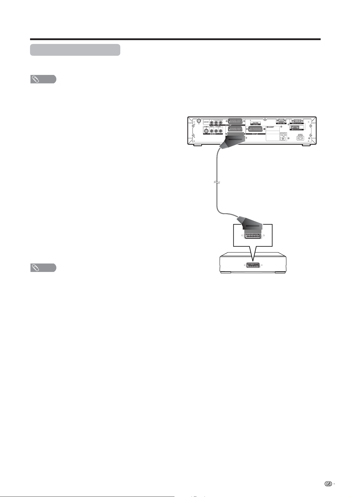
Using external equipment
Using AV Link function
This System incorporates four typical AV Link functions for smooth connections between AVC System and other
audiovisual equipment.
NOTE
• Only works when the audiovisual equipment is connected to the INPUT 2 terminal on the AVC System with AV Link via a
fully wired SCART.
One Touch Play
While the System is in standby mode, it automatically
turns on and plays back the image from the audiovisual
source (e.g. VCR, DVD).
System Standby
When the connected audiovisual equipment (e.g. VCR,
DVD) enters standby mode, so does the System.
WYSIWYR (What You See Is What You Record)
When the remote control unit of the connected VCR
has the WYSIWYR button, you can automatically start
recording by pressing the WYSIWYR button.
Preset Download
Automatically transfers the channel preset information
from the tuner on the System to the one on the
connected audiovisual equipment (e.g. VCR) via the
INPUT 2 terminal.
NOTE
• Refer to operation manuals of each external equipment
for the details.
AVC System (rear view)
SCART cable
(commercially available)
VCR
43
Page 46

Using external equipment
Watching a DVD image
Connecting a DVD player
You can use the INPUT 3 terminal when connecting to a DVD player and other audiovisual equipment.
AVC System (rear view)
SCART cable
(commercially available)
When using component
cable, select
“COMPONENT” for “Input
Select” in the menu.
DVD player
Component cable (commercially available)
TV MENU
Option
Input Select
INPUT SOURCE
TV
INPUT1
INPUT2
INPUT3
INPUT4
PC
Displaying a DVD image
To watch a DVD image, select “INPUT3” from “INPUT
SOURCE” menu using b on the remote control unit
or INPUT on the Display.
Then select “INPUT3” on “Input Select” in the menu to
set the correct input signal type. (See page 52.)
The setting is stored and can be selected in the “INPUT
SOURCE” menu.
NOTE
• Each time b is pressed, the input source toggles.
• If the DVD image does not come in clearly, you may need
to change the input signal type setting on the “Input Select”
menu.
• Refer to your DVD player operation manual for the signal
type.
44
COMPONENT
Y/C
CVBS
RGB
(For INPUT3 signal)
Page 47
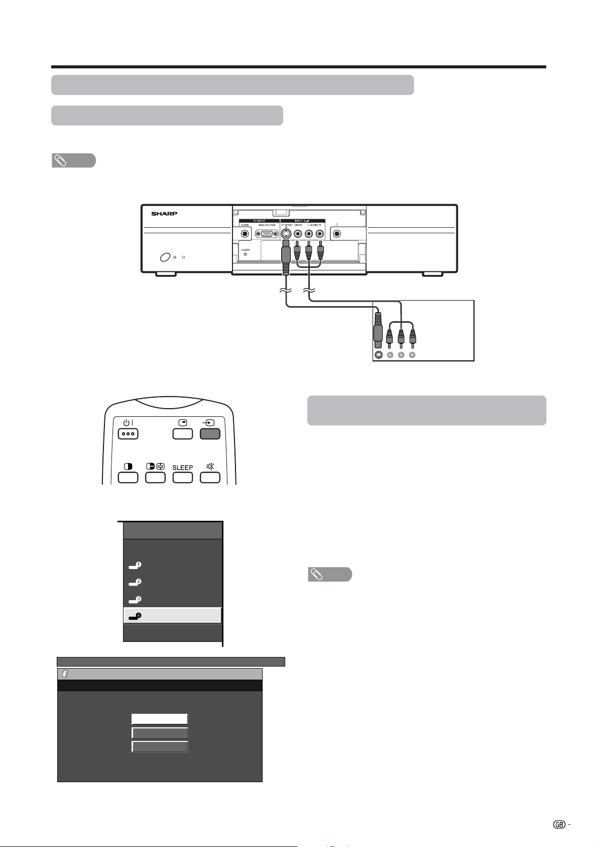
Using external equipment
Enjoying a game console and viewing camcorder images
Connecting a game console or camcorder
A game console, camcorder and some other audiovisual equipment are conveniently connected using the
INPUT 4 terminals.
NOTE
• The S-video terminal has priority over the video terminals.
AVC System (front view)
Composite video cable
(commercially available)
S-video cable
(commercially available)
INPUT SOURCE
TV
INPUT1
INPUT2
INPUT3
INPUT4
PC
Game console/Camcorder
Displaying an image of the game console or
camcorder
To connect a game console or view a camcorder, select
“INPUT4” from the “INPUT SOURCE” menu using b
on the remote control unit or INPUT on the Display.
Then select “INPUT4” on “Input Select” in the menu to
set the correct input signal type. (See page 52.)
The setting is stored and can be selected on the
“INPUT SOURCE” menu.
NOTE
• Each time b is pressed, the input source toggles.
TV MENU
Option
Input Select
AUTO
S-Video
Video
(For INPUT4 signal)
45
Page 48
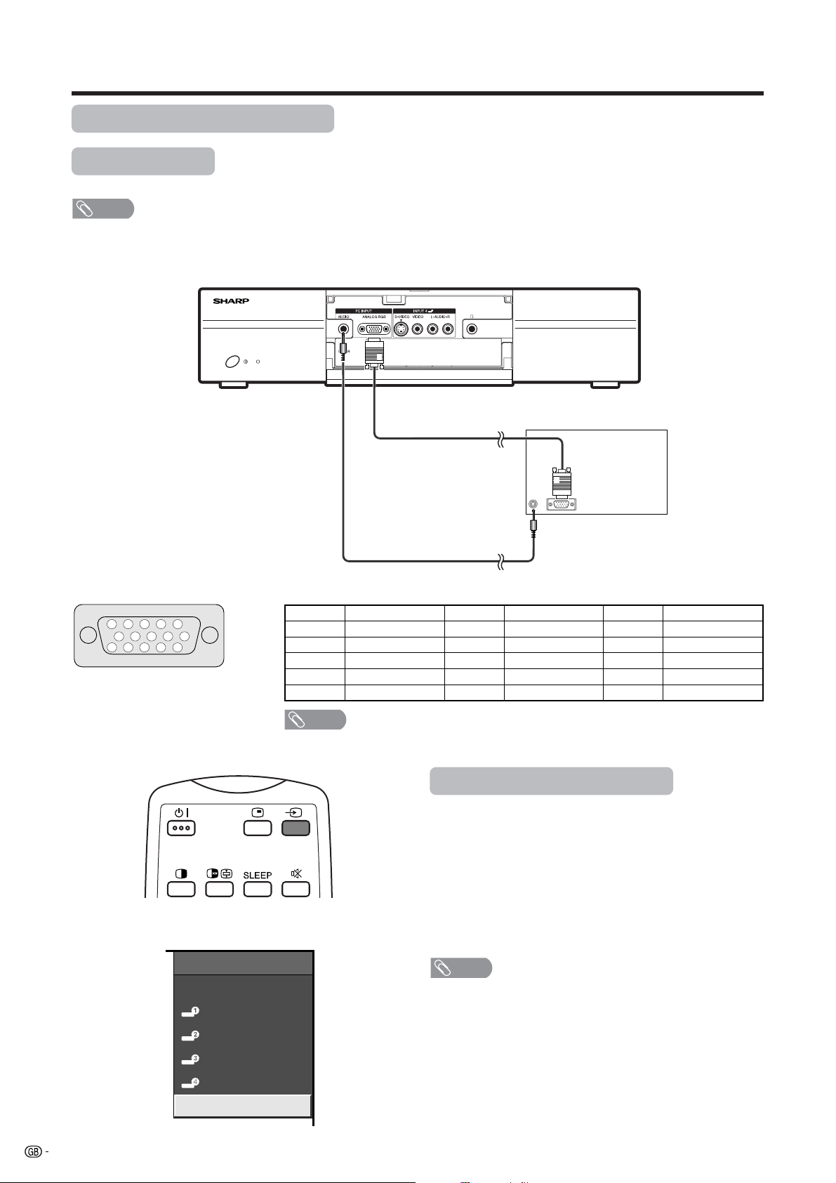
Using external equipment
Viewing an image from a PC
Connecting a PC
Use the PC terminals to connect a PC.
NOTE
• The PC input terminals are DDC1/2B-compatible.
• Refer to page 68 for a list of PC signals compatible with the System.
AVC System (front view)
RGB cable
(commercially available)
Signal names for 15-pin mini D-sub connecter
5
4 321
10
9
15
141312
6
7
8
11
Pin No. Signal name Pin No. Signal name Pin No. Signal name
1 R 6 GND (Ground) q Not connected
2 G 7 GND (Ground) w SDA
3 B 8 GND (Ground) e HD
4 Not connected 9 +5V r VD
5 CSYNC 0 GND (Ground) t SCL
NOTE
• Macintosh adaptor may be required for use for some Macintosh computers.
ø 3.5 mm stereo minijack cable
(commercially available)
Displaying an image from a PC
To view an image from a PC, select “PC” from the
“INPUT SOURCE” menu using b on the remote
control unit or INPUT on the Display.
When connecting to a PC, the correct input signal type
is automatically detected. (See page 56.) If the PC
image does not come in clearly, you may need to set
the Auto Sync. adjustment in the “Setup” menu. (See
page 51.)
PC
46
INPUT SOURCE
TV
INPUT1
INPUT2
INPUT3
INPUT4
PC
NOTE
• Each time b is pressed, the input source toggles.
Page 49

Using external equipment
Connecting external speakers
Rear view
RED BLACKBLACK RED
When using external speakers
• Change the speaker setting to external speakers. (See
page 48.)
Make sure to connect the speaker jack and cable
polarity (L, +) properly
• The speaker jacks have plus (L) and minus (+) polarity.
• Plus is red and minus is black.
• The cables are also divided into plus and minus.
• When connecting the left/right speakers, be sure to
connect the plus/minus jacks with the correct cables.
How to connect the speaker cable
Pull up the lid.
11
1
11
Insert the edge of the
22
2
22
cable.
Put the lid back down.
33
3
33
• Bundle the cables of the external
speakers with clamps as shown above.
CAUTION
• Make sure external speakers have 8 ohm and 10 watt
specifications.
• Connect the plus/minus jacks with the correct cables.
Incorrect connection may cause a short.
NOTE
• See page 8 for bundling the cables of the external
speakers.
• Unplug the AC cord from the AC outlet before installing
the speakers.
47
Page 50

Using external equipment
Selecting speakers
You can output audio using the supplied speakers
(detachable) or other external speakers.
1
2
3
4
Press MENU and the TV MENU (PC MENU)
screen displays.
Press c/d to select “Audio”.
• Audio menu displays.
Press a/b to select “Speaker”, and then
press ENTER.
TV MENU
Audio Power control
USER
Treble
Bass
Balance
Surround
Speaker
Reset
–15
[0]
[0]
–15
[0]
L
Press c/ d to select “External” or
“Detachable”, and then press ENTER.
TV MENU
Audio
Speaker
+15
+15
R
[Off]
[Detachable]
48
DetachableExternal
Page 51

Useful adjustment settings
Image position (for TV/AV input mode)
For adjusting a picture’s horizontal and vertical
position.
1
2
Press MENU and the TV MENU screen
displays.
Press c/d to select “Setup”.
• If password is already set, you are asked to
enter it. Follow the same steps as explained in
“Auto installation”. (See steps 2 and 3 on page
23.)
NOTE
• For resetting all adjustment items to the factory preset
values, press a/b to select “Reset”, and then press
ENTER.
• Adjustments are stored separately according to input
source.
• You can easily move the image position as shown on page
50, but when the power is switched off the image will return
to the previously memorised position.
• This function is available for AV input mode and TV tuner
mode.
Selected item
H-Pos.
V-Pos.
Centres the image by moving it to the left or
right.
Centres the image by moving it up or down.
Description
3
4
Press a/b to select “Position”, and then
press ENTER.
TV MENU
Setup Option
Auto Installation
Programme Setup
Child Lock
Position
WSS
4:3 Mode [Normal]
Rotate
Language
[Off]
[Normal]
[English]
Press a/b to select “H-Pos.” or “V-Pos.”.
TV MENU
Setup
Position
H-Pos. [0] –10 +10
V-Pos. [0] –30
Reset
+30
5
Press c/d to adjust the item to your desired
position.
49
Page 52

Useful adjustment settings
Moving the picture on the screen
You can move the picture around on the screen.
Press a/b/c/d to move an image on the screen to
the desired position. Press ENTER to return to the initial
image position.
NOTE
• While pressing a/b/c/ d, an on-screen image,
“Adjusting Position” displays to the desired position.
• This setting cannot be stored. Once the System shuts
down or enters standby mode, the setting is erased. To
move the picture around the screen again, you must
perform the above procedure again.
• The image position setting using the steps on page 49
can be stored. Select either according to your objectives.
• “TV”, “INPUT1”, “INPUT2”, “INPUT3” and “INPUT4” can
each adjust the image position setting on this page. The
same for WIDE modes.
• An on-screen image from a PC source cannot be moved
around.
• Even when the image fills the screen, its position can be
adjusted with this function.
50
Page 53
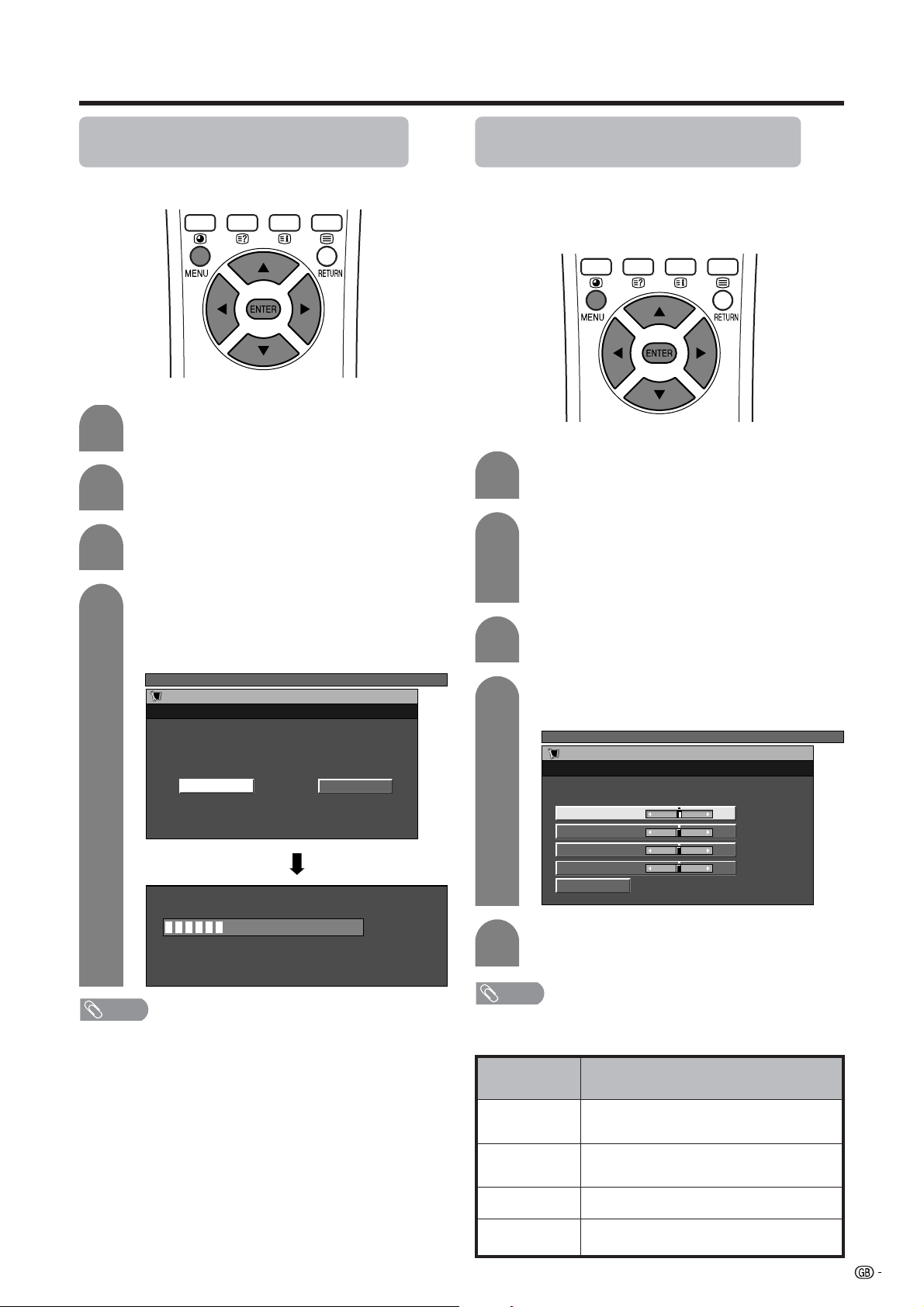
Useful adjustment settings
Auto Sync. adjustment (PC input
mode only)
For automatically adjusting the PC image.
1
2
3
4
Press MENU and the PC MENU screen
displays.
Press c/d to select “Setup”.
• Setup menu displays.
Press a/b to select “Auto Sync.”, and then
press ENTER.
Press c/d to select “Yes”, and then press
ENTER.
• Auto Sync. starts and “Adjusting the image”
displays.
PC MENU
Setup
Auto Sync.
NoYes
Fine Sync. adjustment (PC input
mode only)
Ordinarily you can easily adjust the picture as
necessary to change image position using Auto Sync.
In some cases, however, manual adjustment is needed
to optimise the image.
1
2
3
4
Press MENU and the PC MENU screen
displays.
Press c/d to select “Setup”.
• If password is already set, you are asked to
enter it. Follow the same step as explained in
“Language setting for on-screen display (PC
input mode)”. (See step 2 on page 30.)
Press a/b to select “Fine Sync.”, and then
press ENTER.
Press a/b to select the specific
adjustment item.
PC MENU
Setup
Fine Sync.
30%
NOTE
• When Auto Sync. is successful, “Auto Sync completed
successfully” displays. If not, Auto Sync. failed.
• Auto Sync. may fail even if “Auto Sync completed
successfully” displays.
• Auto Sync. is likely to succeed when an input PC image
has wide vertical stripes (ex. pattern with high contrast
stripes, or cross-hatched).
It may fail when an input PC image is solid (low contrast).
• Be sure to connect the PC to the AVC System and switch
it on before starting Auto Sync.
H-Pos. [0] –90 +90
+60
+90
+20
5
V-Pos.
[0]
–60
Clock
[0]
–90
Phase
[0]
–20
Reset
Press c/d to adjust the item to your
desired position.
NOTE
• For resetting all adjustment items to the factory preset
values, press a/b to select “Reset”, and then press
ENTER.
Selected item
H-Pos.
V-Pos.
Clock
Phase
Centres the image by moving it to the left or
right.
Centres the image by moving it to the up or
down.
Adjusts the clock frequency.
Adjusts the clock phase.
Description
51
Page 54

Useful adjustment settings
Input signal source
Input selection
Can use for selecting the input source.
4
Press a/b/c/d to select a signal type you
want to set, and then press ENTER.
• If the selected signal type is incorrect, an image
does not display or no colour image displays.
For INPUT 1 signal
TV MENU
Option
Input Select
RGBCVBS
For INPUT 2 signal
TV MENU
Option
Input Select
CVBSY/C
1
Press b on the remote control unit or
INPUT on the Display.
• INPUT SOURCE menu displays.
2
Press b on the remote control unit or
INPUT on the Display to select the input
source.
• An image from the selected source
automatically displays.
• You can also select the input source by
pressing a/b.
Input signal setting
For setting the signal type of external equipment.
1
2
3
Press MENU and the TV MENU screen
displays.
Press c/d to select “Option”.
• Option menu displays.
Press a/b to select “Input Select”, and then
press ENTER.
TV MENU
Option
Input Select
Audio Out
Cool Climate
Colour System
[Fixed]
[Off]
[AUTO]
For INPUT 3 signal
TV MENU
Option
Input Select
COMPONENT
Y/C
CVBS
RGB
For INPUT 4 signal
TV MENU
Option
Input Select
AUTO
S-Video
Video
NOTE
• If no (colour) image displays, try to change the other
signal type.
• Check the operation manual of the external equipment
for the signal type.
52
Page 55

Useful adjustment settings
Colour system setting (for TV/AV
input mode)
You can change the colour system to one that is
compatible with the image on the screen.
1
2
3
Press MENU and the TV MENU screen
displays.
Press c/d to select “Option”.
• Option menu displays.
Press a/b to select “Colour System”, and
then press ENTER.
TV MENU
Option
AV mode selection
AV mode gives you five viewing options to choose from
to best match the system environment, which can vary
due to factors like room-brightness, type of programme
watched or the type of image input from external
equipment.
1
2
AV MODE: STANDARD AV MODE: DYNAMIC
Press AV MODE.
• Present AV mode displays.
Press AV MODE again before the mode
displayed on the screen disappears.
• The mode changes as shown below.
AV input mode
Input Select
[Fixed]
[Off]
[AUTO]
4
Audio Out
Cool Climate
Colour System
Press a/b to select a compatible video
signal system of your equipment, and then
press ENTER.
• Some items may be greyed out. They are not
selectable.
TV MENU
Option
Colour System
AUTO
PAL
SECAM
NTSC 3.58
NTSC 4.43
PAL-60
NOTE
• Factory preset value is “AUTO”.
• If “AUTO” is selected, colour system for each channel is
automatically set. If an image does not display clearly,
select another colour system (e.g. PAL, NTSC 4.43).
• This function is available for AV input mode and TV tuner
mode.
AV MODE: USER
AV MODE: STANDARD
Selected item
STANDARD
DYNAMIC
MOVIE
GAME
USER
AV MODE: MOVIE
AV MODE: GAME
PC input mode
AV MODE: USER
Description
For a highly defined image in a normally
bright room
For a clear-cut image emphasising high
contrast for sports viewing
For a movie
Lowers image brightness for easier viewing.
Allows the user to customise settings as
desired. You can set the mode for each
input source.
53
Page 56

Useful adjustment settings
WIDE MODE
Normal
Full 14:9
Zoom 14:9
Panorama
Full
Cinema 16:9
Cinema 14:9
WIDE mode (for TV/AV input mode)
Manual Selection
1
Press f.
• The WIDE MODE menu displays.
• The menu lists the wide mode options selectable
for the type of video signal currently received.
2
Auto Selection
If you set “WSS” and “4:3 Mode” in the Setup menu on
page 57, the optimum WIDE mode is automatically
chosen for every broadcast containing the WSS
information.
“WSS” menu
To enable Auto Selection, set “WSS” in the Setup menu
to “On”. (See page 57.)
“4:3 Mode” menu
To set the type of the wide screen, select “Normal” or
“Panorama” in the 4:3 Mode menu. (See page 57.)
Press f or a/b while the WIDE MODE
menu displays on the screen.
• As you toggle down the options, each is
immediately reflected on the Display. No need
to press ENTER.
4:3 Mode set to “Normal” 4:3 Mode set to “Panorama”
Selected item
Normal
Full 14:9
Zoom 14:9
Panorama
Full
Cinema 16:9
Cinema 14:9
For 4:3 “standard” pictures. A side bar appears on each side.
For 14:9 squeeze pictures. A thin side bar appears on each side.
For 14:9 letterbox pictures. A thin side bar appears on each side, and you may also see bars on
the top and bottom with some programmes.
In this mode the picture is progressively stretched toward each side of the screen.
For 16:9 squeeze pictures.
For 16:9 letterbox pictures. Bars may appear on the top and bottom with some programmes.
For 14:9 letterbox pictures. Bars may appear on the top and bottom with some programmes.
Normal Full 14:9
NOTE
• If the broadcast signal contains no WSS information, Auto
Selection will not function even when the WSS option is
enabled.
• This function is available for AV input mode and TV tuner
mode.
Description
Zoom 14:9
54
Panorama
FullCinema 16:9Cinema 14:9
Page 57

Useful adjustment settings
a
Screen size images.
Input Signal
a
Input signal
(640m480)
WIDE MODE
Normal
Full
WIDE mode (for PC input mode)
You can select the screen size.
NOTE
• Connect the PC before making adjustments. (See page
46.)
• Selectable screen size may vary with input signal type.
Dot by Dot
Cinema
Input signal
(1024m768)
1
2
Press f.
• The WIDE MODE menu displays.
Press f or a/b to select a desired item on
the menu.
WIDE MODE
Full
Dot by Dot
Cinema
Normal Full CinemaDot by Dot
640g480 Keeps the original
Input Signal
1024g768
aspect ratio in a full
screen display.
Normal Full CinemaDot by Dot
An image fully fills
the screen.
An image fully fills
the screen.
Detects the
resolution of the
signal and displays
an image with the
same number of
pixels on the screen.
Detects the
resolution of the
signal and displays
an image with the
same number of
pixels on the screen.
Keeps the original
aspect ratio in a full
screen display. The
top and bottom of
the image is slightly
cropped.
Keeps the original
aspect ratio in a full
screen display. The
top and bottom of
the image is slightly
cropped.
55
Page 58

Useful adjustment settings
Input signal (PC input mode only)
• Some input signals may have to be registered manually
to display properly.
• The pairs of input signals (resolutions) in the list below
are not distinguishable when received. In such case, you
have to set the correct signal manually. After setting once,
it will display when the same signal (resolution) is input
again.
640g400
640g480
1024g768
NOTE
• You can only select the “Input Signal” on the Setup menu
when receiving one of the 6 input signals listed above.
720g400
848g480
1280g768
1
2
3
4
Press MENU and the PC MENU screen
displays.
Press c/d to select “Setup”.
• Setup menu displays.
Press a/b to select “Input Signal” and then
press ENTER.
PC MENU
Setup Option
Input Signal
Auto Sync.
Fine Sync.
Rotate
Language
[Normal]
[English]
Press a/b to select the desired input signal
on the display.
PC MENU
Setup
Input Signal
640 x 480
848 x 480
(Example)
56
Page 59

Useful adjustment settings
Wide screen signalling (WSS) (for
TV/AV input mode)
WSS allows a television to switch automatically among
the different screen formats.
1
2
3
Press MENU and the TV MENU screen
displays.
Press c/d to select “Setup”.
• If password is already set, you are asked to
enter it. Follow the same steps as explained in
“Auto installation”. (See steps 2 and 3 on page
23.)
Press a/b to select “WSS”, and then press
ENTER.
TV MENU
Setup Option
Auto Installation
Programme Setup
Child Lock
Position
WSS
4:3 Mode [Normal]
Rotate
Language
[Off]
[Normal]
[English]
Picture aspect ratio (for TV/AV input
mode)
The WSS signal has 4:3 auto-switching that allows you
to select between Normal and Panorama.
1
2
3
4
Press MENU and the TV MENU screen
displays.
Press c/d to select “Setup”.
• If password is already set, you are asked to
enter it. Follow the same steps as explained in
“Auto installation”. (See steps 2 and 3 on page
23.)
Press a/b to select “4:3 Mode”, and then
press ENTER.
TV MENU
Setup Option
Auto Installation
Programme Setup
Child Lock
Position
WSS
4:3 Mode [Normal]
Rotate
Language
[Off]
[Normal]
[English]
Press c/d to select “Normal” or
“Panorama”, and then press ENTER.
TV MENU
Setup
4:3 Mode
NormalPanorama
4
Press c/d to select “On” or “Off”, and then
press ENTER.
TV MENU
Setup
WSS
OffOn
WSS signal 4:3 screen
4:3 mode “Normal”
Selected item
Normal
Panorama
Normal range keeping 4:3 or 16:9 aspect
ratio
Wide image without side bars
4:3 mode “Panorama”
Description
NOTE
• Try to set WIDE mode if an image does not switch to the correct screen format. When the broadcast signal contains no
WSS information, the function will not work even if enabled. See page 54.
• This function is available for AV input mode and TV tuner mode.
57
Page 60

Useful adjustment settings
Rotate
You can set the orientation of the picture.
AV input mode
1
2
3
4
Press MENU and the TV MENU screen
displays.
Press c/d to select “Setup”.
• If password is already set, you are asked to
enter it. Follow the same steps as explained in
“Auto installation”. (See steps 2 and 3 on page
23.)
Press a/b to select “Rotate”, and then press
ENTER.
TV MENU
Setup Option
Auto Installation
Programme Setup
Child Lock
Position
WSS
4:3 Mode [Normal]
Rotate
Language
[Off]
[Normal]
[English]
Press a/b to select the desired mode, and
then press ENTER.
TV MENU
Setup
Rotate
1
2
3
PC input mode
Press MENU and the PC MENU screen
displays.
Press c/d to select “Setup”.
• If password is already set, you are asked to
enter it. Follow the same step as explained in
“Language setting for on-screen display (PC
input mode)”. (See step 2 on page 30.)
Press a/b to select “Rotate”, and then press
ENTER.
PC MENU
Setup Option
Input Signal
Auto Sync.
Fine Sync.
Rotate
Language
[Normal]
[English]
Normal
Mirror
Upside Down
Rotate
[Normal]: normal image.
[Mirror]: mirror image.
[Upside Down]: upside
down image.
ABC
4
ABC
NOTE
• If you choose “Mirror” or “Rotate”, the sound orientation also changes.
ABC
Press a/b to select the desired mode, and
then press ENTER.
PC MENU
Setup
Rotate
Normal
Mirror
Upside Down
Rotate
[Rotate]: rotated image.
ABC
58
Page 61

Useful adjustment settings
Audio out
Allows you to select what controls the audio output.
1
2
Press MENU and the TV MENU (PC MENU)
screen displays.
Press c/d to select “Option”.
• Option menu displays.
Selected item
Fixed
Variable
• Sound via speakers is adjusted with
il/k on the remote control unit or the
Display.
• Sound via the AV OUTPUT terminal is not
adjustable and constantly outputs.
• Sound via the AV OUTPUT terminal is
adjusted with il/k on the remote
control unit or the Display.
• Sound via speakers is muted.
Description
Sleep timer
Allows you to set a time when the TV automatically
switches to standby.
3
4
Press a/b to select “Audio Out”, and then
press ENTER.
TV MENU
Option
Input Select
Audio Out
Cool Climate
Colour System
(On-screen display for AV input mode.)
PC MENU
Option
Audio Out
Cool Climate
(On-screen display for PC input mode.)
[Fixed]
[Off]
[AUTO]
[Fixed]
[Off]
Press c/d to select “Fixed” or “Variable”,
and then press ENTER.
TV MENU
Option
Audio Out
1
2
Press SLEEP.
• Remaining time displays when sleep timer has
been set.
Sleep Timer: Remain 120
Each time you press SLEEP, the remaining
time switches as shown below.
• When the time has been set, countdown
automatically starts.
• Five minutes before the preset of time expires,
the remaining time displays each minute.
30 60 90
0
120
(minutes)
VariableFixed
NOTE
• Select “0” by pressing SLEEP to cancel the sleep timer.
59
Page 62

Useful adjustment settings
Cool climate
Improves LCD response when viewing fast-moving
images. The effect is greater at low room temperatures
(at or below 15˚C/59˚F).
1
2
3
4
AV input mode
Press MENU and the TV MENU screen
displays.
Press c/d to select “Option”.
• Option menu displays.
Press a/b to select “Cool Climate”, and then
press ENTER.
TV MENU
Option
Input Select
Audio Out
Cool Climate
Colour System
Press c/d to select “On”, and then press
ENTER.
TV MENU
Option
Cool Climate
[Fixed]
[Off]
[AUTO]
1
2
3
4
PC input mode
Press MENU and the PC MENU screen
displays.
Press c/d to select “Option”.
• Option menu displays.
Press a/b to select “Cool Climate”, and then
press ENTER.
PC MENU
Option
Audio Out
Cool Climate
Press c/d to select “On”, and then press
ENTER.
PC MENU
Option
Cool Climate
[Fixed]
[Off]
OffOn
NOTE
• Cool climate may cause image noise. If this occurs turn
the function “Off”.
60
OffOn
NOTE
• Cool climate may cause image noise. If this occurs turn
the function “Off”.
Page 63

Useful adjustment settings
Password setting for child lock (for
TV/AV input mode)
Allows you to use a password to protect certain settings
from being accidentally changed.
Setting a password
1
2
3
Press MENU and the TV MENU screen
displays.
Press c/d to select “Setup”.
• Setup menu displays.
Press a/b to select “Child Lock”, and then
press ENTER.
TV MENU
Setup Option
Auto Installation
Programme Setup
Child Lock
Position
WSS
4:3 Mode [Normal]
Rotate
Language
[Off]
[Normal]
[English]
6
Enter the same 4-digit number as in step 5
to confirm.
• “The new password is registered.” displays.
NOTE
• To view a locked channel (Lock setting in Programme
Setup “Manual” is set to “On”), you must enter a password.
(See page 28.) When you select a locked channel, a
password prompt message pops up. Press ENTER to
display the password input window.
Clearing the password
Allows you to clear your password.
1
2
3
Press MENU and the TV MENU screen
displays.
Press c/d to select “Setup”.
• You are asked to enter the password. Follow
the same steps as explained in “Auto
installation” (See steps 2 and 3 on page 23.)
Press a/b to select “Child Lock”, and then
press ENTER.
TV MENU
Setup Option
Auto Installation
Programme Setup
Child Lock
Position
WSS
4:3 Mode [Normal]
Rotate
Language
[Off]
[Normal]
[English]
4
5
Press a/b to select “Password”, and then
press ENTER.
TV MENU
Setup
Child Lock
Password
Password Clear
Enter the 4-digit number as a password using
0 – 9.
TV MENU
Setup
Child Lock
New Password
Reconfirm
–––
–
––––
4
Press a/b to select “Password Clear”, and
then press ENTER.
5
Press c/d to select “Yes”, and then press
ENTER.
• Your password is cleared.
TV MENU
Setup
Child Lock
Password
Password Clear
Yes No
NOTE
• As a precautionary measure, make a note of your
password and keep it in a familiar place. If you lose or
forget your password, initialise the System to return
all settings except for the TV channel settings to factory
preset values. (See page 75.)
• This function is available for AV input mode and TV tuner
mode.
61
Page 64

Useful features
Dual screen functions
Allows you to display two pictures on the screen at
one time.
Dual screen
You can display two same-sized pictures except when
inputting from a PC INPUT terminal.
3
4
• This function does not work under the following input
conditions:
1PC INPUT mode,
2Two pictures from the same source (e.g. INPUT 1 and
3Two pictures with different vertical frequency (e.g. PAL
• When this function is not available, “No dual screen display
available.” will display.
Press b to select another input source on
the active screen.
• A selected image displays.
Press c to exit dual screen.
NOTE
INPUT 1),
and PAL-60).
1
2
Press c.
• Dual screen displays and a selected input
source image displays.
z
z
Press c/d to set either screen to be active.
•“z” displays on the active screen, which has
sound output.
62
Page 65

Useful features
Picture and still image
You can display two same-sized pictures – one moving
and one still – when inputting from an AV source.
1
2
3
• This function does not work in PC input mode.
• When this function is not available, “No still image display
available.” will display.
• The still image automatically goes out after 30 minutes.
Press d.
• A moving image displays on the left screen and
a still image displays on the right screen. The
still image is one frame captured from a moving
image at the moment you press d.
FREEZE
Update the still image by pressing ENTER.
• Each time you press ENTER, the image on the
right screen updates.
Press d to exit still image.
NOTE
63
Page 66

Useful features
Teletext function
What is Teletext?
Teletext broadcasts pages of information and
entertainment to specially equipped television sets.
Your System receives Teletext signals broadcast by a
TV network, and decodes them into graphical format
for viewing. News, weather and sports information,
stock exchange prices and programme previews are
among the many services available.
Teletext mode
Teletext is turned on/off with m on the remote control
unit. You can operate your System in Teletext mode
directly by inputting commands with the remote control
unit.
TELETEXT
TELETEXT
When viewing the Teletext information
• Press CH
• Press CH
aa
a (w) to increase the page number.
aa
bb
b (x) to decrease the page number.
bb
Turning on and off Teletext
1
2
3
Select a TV channel or external input source
providing the Teletext programme.
Press m to display the Teletext.
Press m again to display the Teletext on the
right screen and normal image on the left
screen.
• Each time you press m, the screen switches
as shown upper right.
• If you select a programme with no Teletext
signal, “No Teletext available.” displays.
• The same message displays during dual
screen or other modes if no Teletext signal is
available.
Button functions
Colour (RED/GREEN/YELLOW/BLUE):
You can select a group or block of pages displayed in
the coloured brackets at the bottom of the screen by
pressing the corresponding Colour (RED/GREEN/
YELLOW/BLUE) on the remote control unit.
TELETEXT
GREEN
RED
0 – 9:
Directly select any page from 100 to 899 by using 0 –
9.
v:
Each time you press v, the TELETEXT image switches
as shown below.
Full
Upper half
k:
To reveal hidden information such as an answer to a
quiz, press k.
• Press k again to hide the information.
u:
To stop updating Teletext pages automatically, press
u.
• Press u again to release the hold mode.
Lower half
YELLOW BLUE
64
Page 67

Useful features
Displaying Subpages
You can display several subpages as they are
transmitted.
Displaying TOP Overview
When receiving TOP Teletext, you can read a TOP text
overview.
1
2
3
Press m to display Teletext.
Press l to display the TOP Overview as
shown below.
TOP Overview screen
INDEX
BLOCK PAGES
TV PROGRAMS
COLOR BAR
WEATHER
NEWS
MOVIE
LOCAL
SPORTS
BLOCK 1
BLOCK 2
BLOCK 3
GROUP PAGES
FOOT BALL
BASKETBALL
TENNIS
SKI
JUDO
SWIM
GROUP 1
GROUP 2
GROUP 3
GROUP 4
Select the desired block or group by using
a/b/c/d.
1
2
3
Press m to display Teletext.
Press j to display the subpage as shown
below.
Subpage screen
203 203TEXT 01:44:37
–+
0005 ‹‹ 02 03 04 05 06
Select the desired subpage by using c/d/
RED/GREEN.
• 0 – 9 directly selects the desired subpage.
4
5
Press ENTER to display the selected block
or group pages.
Press l to exit the TOP Overview screen.
4
Press j to exit the subpage screen.
aa
• If you press CH
page will change to the next/previous page and
simultaneously exit the subpage screen.
bb
a/CH
b(w/x), the present
aa
bb
65
Page 68

Useful features
Time display
You can display the time information included in the
Teletext. Follow the steps below to display the time.
1
• The time is not captured when a selected channel has no
Teletext information.
2
3
4
• The time display cannot be stored once the power is
turned off. When you turn on the power, perform steps 1 –
4 again.
Select a TV channel providing Teletext
information.
(The time information is automatically
captured.)
NOTE
Press C. The channel display will appear
on the Display.
Press C again within the three-second
interval the channel display is on the screen.
Time information will display on the lower left
of the screen for about three seconds.
Even when you change the TV channel, you
can display the time information with steps
2 – 3 above.
NOTE
66
Page 69

Appendix
Troubleshooting
Problem Possible Solution
• No power.
• Unit cannot be operated.
• Remote control unit does not
operate.
• Picture is cut off.
• Strange colour, light colour, or
dark, or colour misalignment.
• Make sure the Display and the AVC System are connected correctly. (See page
7.)
• Check if you pressed B on the remote control unit. (See page 15.)
If the indicator on the Display lights up red, press B.
• Is the AC cord disconnected? (See page 14.)
• Has the main power been turned on? (See page 15.)
• External influences such as lightning, static electricity, etc., may cause improper
operation. In this case, operate the unit after first turning the power of the Display
and the AVC System, or unplugging the AC cord and re-plugging it in after 1 or
2 minutes.
• Are batteries inserted with polarity (e, f) aligned? (See page 10.)
• Are batteries worn out? (Replace with new batteries.)
• Are you using it under strong or fluorescent lighting?
• Is a fluorescent light illuminated to remote control sensor?
• Is the image position correct? (See pages 49 and 50.)
• Are screen mode adjustments such as picture size made correctly? (See pages
54 to 57.)
• Adjust the picture tone. (See pages 31 to 35 and 60.)
• Is the room too bright? The picture may look dark in a room that is too bright.
• Check the colour system setting. (See pages 27 and 53.)
• Check the input signal setting. (See page 52.)
• Power is suddenly turned off.
• No picture.
• No sound.
• The unit’s internal temperature has increased.
Remove any objects blocking vent or clean.
• Check the power control setting. (See pages 37 to 39.)
• Check the sleep timer setting. (See page 59.)
• Is connection to other components correct? (See pages 40 to 46.)
• Has input signal setup been done correctly after connection? (See page 52.)
• Is the correct input selected? (See page 52.)
• Is a non-compatible signal being input? (See page 68.)
• Is picture adjustment correct? (See pages 31 to 35.)
• Is the volume too low? (See page 19.)
• Is “Variable” selected in “Audio Out”? (See page 59.)
Cautions regarding use in high and low temperature environments
• When the unit is used in a low temperature space (e.g. room, office), the picture may leave trails or appear
slightly delayed. This is not a malfunction, and the unit will recover when the temperature returns to normal.
• Do not leave the unit in a hot or cold location. Also, do not leave the unit in a location exposed to direct sunlight
or near a heater, as this may cause the cabinet to deform and the LCD panel to malfunction.
Storage temperature: –20°C to +60°C (–4°F to +140°F).
67
Page 70

Appendix
PC compatibility chart
Resolution Frequency
640g400
720g400
640g480
800g600
832g624
1024g768
1280g768
1280g1024 60 Hz
85 Hz
70 Hz
85 Hz
60 Hz
65 Hz
72 Hz
75 Hz
85 Hz
56 Hz
60 Hz
72 Hz
75 Hz
85 Hz
74.5 Hz
60 Hz
70 Hz
75 Hz
85 Hz
60 Hz
Remarks
Macintosh 13 (67 Hz)
Macintosh 16
Macintosh 19
Apple and Macintosh are registered trademarks
of Apple Computer, Inc.
DDC is a registered trademark of Video Electronics
Standards Association.
Power Management is a registered trademark of
Sun Microsystems, Inc.
VGA and XGA are registered trademarks of
International Business Machines Co., Inc.
68
Page 71

Appendix
RS-232C port specifications
PC Control of the System
• When a program is set, the display can be controlled from the PC using the RS-232C terminal.
The input signal (PC/video) can be selected, the volume can be adjusted and various other adjustments and
settings can be made, enabling automatic programmed playing.
• Attach an RS-232C cable cross-type (commercially available) to the supplied Din-D/sub RS-232C for the
connections.
NOTE
• This operation system should be used by a person who is accustomed to using PCs.
Communication conditions
Set the RS-232C communications settings on the PC to match the display’s communications conditions. The
display's communications settings are as follows:
Baud rate:
Data length:
Parity bit:
Stop bit:
Flow control:
Communication procedure
Send the control commands from the PC via the RS-232C connector.
The Display operates according to the received command and sends a response message to the PC.
Do not send multiple commands at the same time. Wait until the PC receives the OK response before sending
the next command.
9,600 bps
8 bits
None
1 bit
None
Command format
Eight ASCII codes e CR
C1 C2 C3 C4 P1 P2 P3 P4
Parameter
Input the parameter values, aligning left, and fill with blank(s) for the remainder. (Be sure that four values are input for the
parameter.)
When the input parameter is not within an adjustable range, “ERR” returns. (Refer to “Response code format”.)
No problem to input any numerical value for “x” on the table.
Command 4-digits: Command. The text of four characters.
Parameter 4-digits: Parameter 0 – 9, x, blank, ?
Return codeCommand 4-digits Parameter 4-digits
0
0009
– 30
100
0055
When “?” is input for some commands, the present setting value responds.
?
????
69
Page 72

Appendix
Response code format
Normal response
OK
Problem response (communication error or incorrect command)
ERR
Commands
Return code (0DH)
Return code (0DH)
CONTROL ITEM COMMAND PARAMETER
P
O
W
R
POWER SETTING
INPUT SELECTION A
INPUT SELECTION B
AV MODE
SELECTION
VOLUME
POSITION
I
I
I
I
I
I
I
I
I
I
I
I
I
A
A
A
A
A
A
V
H
H
V
V
C
P
0
T
G
D
x
T
V
D
0
T
V
D
*
A
V
D
*
P
C
D
x
N
P
1
0
N
P
1
1
N
P
2
0
N
P
2
1
N
P
3
0
N
P
3
1
N
P
3
2
N
P
3
3
V
M
D
0
V
M
D
1
V
M
D
2
V
M
D
3
V
M
D
4
V
M
D
5
O
L
M
*
P
O
S
*
P
O
S
*
P
O
S
*
P
O
S
*
L
C
K
*
H
S
E
*
POWER OFF (STANDBY)
_
_
_
INPUT SWITCHING (TOGGLE)
TV (CHANNEL FIXED)
_
_
_
TV (CHANNEL SELCTION) (1 – 99)
*
_
_
INPUT1 – 4 (1 – 4)
_
_
_
PC
INPUT1 (CVBS)
_
_
_
INPUT1 (RGB)
_
_
_
INPUT2 (CVBS)
_
_
_
INPUT2 (Y/C)
_
_
_
INPUT3 (CVBS)
_
_
_
INPUT3 (Y/C)
_
_
_
INPUT3 (RGB)
_
_
_
INPUT3 (COMPONENT)
_
_
_
TOGGLE
_
_
_
STANDARD
_
_
_
DYNAMIC
_
_
_
MOVIE
_
_
_
GAME
_
_
_
USER
_
_
_
VOLUME (0 – 60)
*
_
_
H-POSITION (AV) (10 – 10)
*
*
_
H-POSITION (PC) (90 – 90)
*
*
_
V-POSITION (AV) (30 – 30)
*
*
_
V-POSITION (PC) (60 – 60)
*
*
_
CLOCK (90 – 90)
*
*
_
PHASE (20 – 20)
*
*
_
CONTROL
CONTENTS
CONTROL ITEM COMMAND PARAMETER
WIDE MODE
SRS
DUAL SCREEN
CHANNEL
TEXT
W
I
D
E
0
W
I
D
E
1
W
I
D
E
2
W
I
D
E
3
W
I
D
E
4
W
I
D
E
5
W
I
D
E
6
W
I
D
E
7
W
I
D
E
8
W
I
D
E
9
W
I
D
E
1
W
I
D
E
1
S
R
S
S
0
S
R
S
S
1
S
R
S
S
2
S
R
S
S
3
S
R
S
S
4
T
W
I
N
0
T
W
I
N
1
D
C
C
H
*
C
H
U
P
x
C
H
D
W
x
T
E
X
T
0
T
E
X
T
1
D
C
P
G
*
TOGGLE
_
_
_
NORMAL
_
_
_
FULL 14:9
_
_
_
ZOOM 14:9
_
_
_
PANORAMA
_
_
_
FULL
_
_
_
CINEMA 16:9
_
_
_
CINEMA 14:9
_
_
_
NORMAL
_
_
_
FULL
_
_
_
DOT BY DOT
0
_
_
CINEMA
1
_
_
TOGGLE
_
_
_
OFF
_
_
_
SRS
_
_
_
FOCUS
_
_
_
SRS FOCUS
_
_
_
DUAL SCREEN OFF
_
_
_
DUAL SCREEN ON
_
_
_
DIRECT CHANNEL (1 – 99)
*
_
_
CHANNEL UP
CHANNEL DOWN
TEXT OFF
_
_
_
TEXT ON (TOGGLE)
_
_
_
DIRECT PAGE JUMP (100 – 899)
*
*
_
CONTROL
CONTENTS
NOTE
• If an underbar (_) appears in the parameter column, enter a space.
• If an asterisk (*) appears, enter a value in the range indicated in brackets under CONTROL CONTENTS.
70
Page 73

Appendix
Connecting pin assignments for SCART
Various audio and video devices may be connected via the SCART terminals.
13579111315171921
2468101214161820
SCART (INPUT 1)
1. Audio right output
(TV Monitor out)
2. Audio right input
3. Audio left output
(TV Monitor out)
4. Common earth for audio
5. Earth for blue
6. Audio left input
7. Blue input
8. Audio-video control
9. Earth for green
10. Not used
11. Green input
12. Not used
13. Earth for red
14. Not used
15. Red input
16. Red/Green/Blue control
17. Earth for video
18. Earth for Red/Green/Blue
19. Video output
20. Video input
21. Plug shield
control
(TV Monitor out)
SCART (INPUT 2)
1. Audio right output
2. Audio right input
3. Audio left output
4. Common earth for audio
5. Earth
6. Audio left input
7. Not used
SCART (INPUT 3)
1. Audio right output
2. Audio right input
3. Audio left output
4. Common earth for audio
5. Earth
6. Audio left input
7. Blue input
8. Audio-video control
9. Earth
10. AV LINK control
11. Not used
12. Not used
13. Earth
14. Not used
8. Audio-video control
9. Earth
10. Not used
11. Green input
12. Not used
13. Earth
14. Not used
15. Chroma S-Video input
16. Not used
17. Earth for video
18. Earth
19. TV Monitor output
20. Video input/S-video input
21. Plug shield
15. Red input/Chroma S-Video
input
16. Red/Green/Blue control
17. Earth for video
18. Earth
19. TV Monitor output
20. Video input/S-video input
21. Plug shield
71
Page 74

Appendix
Specifications
Item 37o LCD COLOUR TV, Model:LC-37HV4E
LCD panel 37o Advanced Super View & BLACK TFT LCD
Number of dots 3,147,264 dots (1366 g 768 g 3 dots)
Video Colour System PAL/SECAM/NTSC 3.58/NTSC 4.43/PAL 60
TV
Function
TV-standard (CCIR)
Receiving
Channel
VHF/UHF
CATV
B/G, D/K, I, L/L’
E2–E69ch, F2–F10ch, I21–I69ch, IR A–IR Jch
Hyper-band, S1–S41ch
TV-Tuning System
STEREO/BILINGAL NICAM/IGR
Brightness 430 cd/m
Backlight 60,000 hours (at Manual 0 position)
Viewing angles H : 170° V : 170°
Audio amplifier 10W g 2
Speakers Ø 8 cm 2pcs
Terminals SCART (AV in, RGB in, TV out)
OSD language
AVC
System
Rear INPUT 1
INPUT 2
INPUT 3
ANTENNA 75 q Din Type
AV OUTPUT Audio (Variable, Fixed), S-VIDEO out, AV out
DC OUTPUT DC6.5V 7W MAX
Front
INPUT 4 S-VIDEO, AV in
PC
Headphones
Auto Preset 99 ch, Auto Label, Auto Sort
2
SCART (AV in/out, S-VIDEO in, AV Link)
SCART (AV in/out, S-VIDEO in, RGB in), Component
15 Pin mini D-Sub, Audio in (Ø 3.5mm jack)
Ø 3.5mm jack
English/German/French/Italian/Spanish/Dutch/Swedish/Portuguese/Greek/
Finnish/Russian/Turkish
Power Requirement
Power
Consumption
Weight
Accessories
• As a part of policy of continuous improvement, SHARP reserves the right to make design and specification changes for
product improvement without prior notice. The performance specification figures indicated are nominal values of production
units. There may be some deviations from these values in individual units.
AVC System
Display
AVC System
Display
Optional accessories
The listed optional accessories are available for the LCD
colour TV. Please purchase them at your nearest shop.
• Additional optional accessories may be available in near
future. When purchasing, please read the newest
catalogue for compatibility and check the availability.
72
AC 220–240 V, 50/60 Hz
32 W (0.7W Standby)
138 W (0.9W Standby) (Method IEC60107)
5.4 kg (w/o stand), 5.5 kg (with stand)
16.5 kg (Display only), 19.9 kg (with Display and speakers), 24.0 kg (with
Display, speakers and stand)
Operation manual, Remote control unit (g1), System cable (g1), AC cord
(g2), LR6 (“AA” size) Alkaline battery (g2), Stand unit (g1), Speaker (Lg1,
Rg1), Speaker screw (g4), Cable clamp (Large g1, Small g2)
No.
1 AN-37AG1
2 AN-07SC1
Part name Part number
Wall mount bracket
System cable
(7 meters)
Page 75

Dimensional drawings
Display
117.5
819.6
545
948
460.8
117.5
Unit: mm
305
82
87.5
87.5
587
697
1184
200
408.5
110200183.5
305545
73
Page 76
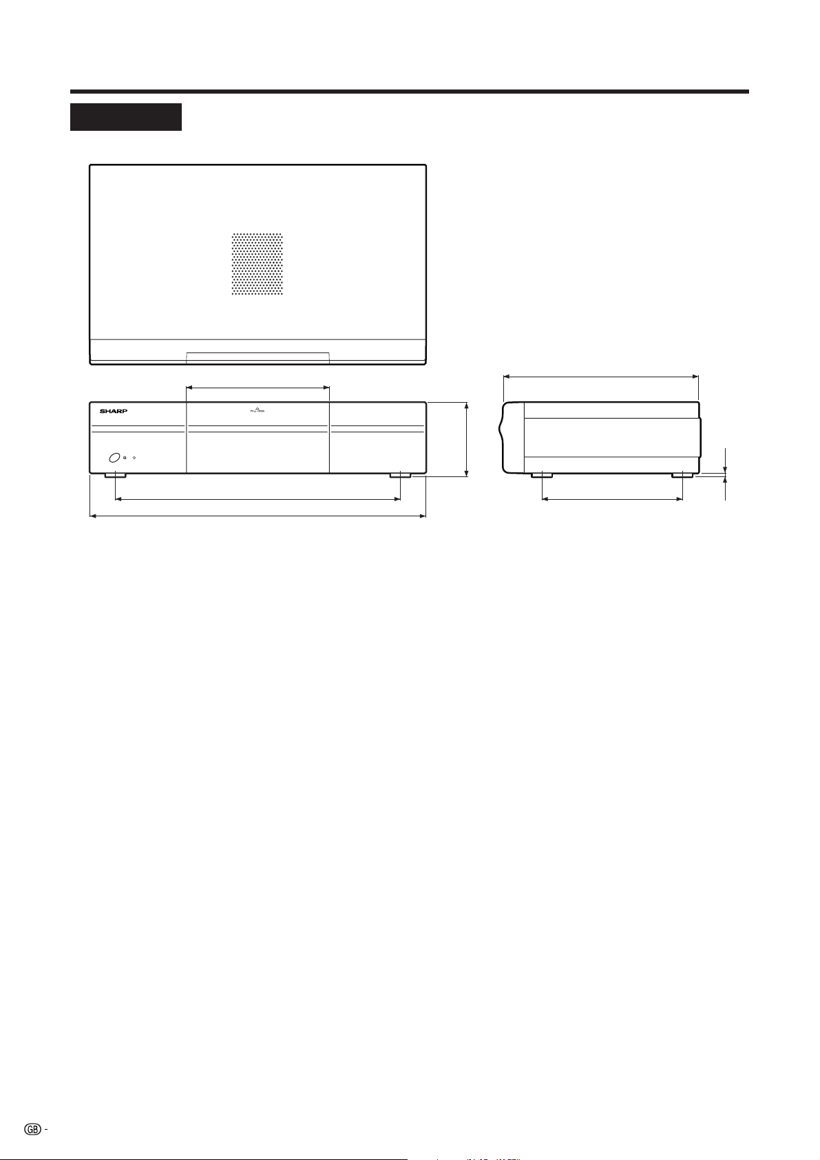
Dimensional drawings
AVC System
183
365
430
Unit: mm
250
95
5
180
74
Page 77

HOW TO SET THE FACTORY PRESETS
Press and hold down CLEAR on the AVC System while it is in standby mode. Then press STANDBY/ON
button on the Display or B on the remote control unit to turn the System on.
All setting items (except TV channel) return to the factory presetting.
NOTE
• Running the factory presetting operation also clears the password.
You can run the Auto Installation again by using the following steps.
1 Turn on the power of the Display and the AVC System.
2 Press MENU. (Make sure the menu screen displays.)
3 Press b to select “Setup”.
4 Press ENTER.
NOTE
• If the password setting screen displays, you need to enter your password.
• If you forget your password, refer to HOW TO SET THE FACTORY PRESETS above.
5 Press a/b to select “Auto Installation”.
6 Press ENTER.
“Auto Installation completed” displays. After that, the screen changes to the TV mode.
The password is .
NOTE
• As a precautionary measure, make a note of your password above, scissor it from this manual, and keep it in a familiar
place.
75
Page 78

SHARP CORPORATION
A
Printed on post-consumer recycled paper.
Gedruckt auf Nachverbraucher-Recyclingpapier.
Imprimé sur du papier recyclé.
Printed in Japan
Gedruckt in Japan
Imprimé au Japon
TINS-A476WJZZ
03P01-JKG
 Loading...