

Page 1

LC-32/40/46LE705E/S, LU705E/S, LX705E, LC-52LE705E/S
SERVICE MANUAL
No. SX9D1LC32L705
LCD COLOUR TELEVISION
LC-32LE705E/S, LC-32LU705E/S
LC-32LX705E
LC-40LE705E/S, LC-40LU705E/S
LC-40LX705E
LC-46LE705E/S, LC-46LU705E/S
LC-46LX705E
MODELS
In the interests of user-safety (Required by safety regulations in some countries) the set should be restored to its original
condition and only parts identical to those specified should be used.
LC-52LE705E/S
OUTLINE
LC-32/40/46LE705E/S, LU705E/S, LX705E, LC-52LE705E/S has been issued to cover the modifications of some parts in reference
to redesigned LCD panel module of Model LC-32/40/46/52LE700E/S. In this Service Manual, the modifications from Model LC-32/
40/46/52LE700E/S (No. S89B4LC32L700) are focused on. For what is left out herein, please refer back to the Service Manual of
the previous model LC-32/40/46/52LE700E/S (No. S89B4LC32L700).
CONTENTS
OUTLINE AND DIFFERENCES FROM BASE MODEL
OUTLINE.............................................................i
LIST OF CHANGED PARTS
(LC-32LE705E/S, LU705E/S, LX705E)...............i
LIST OF CHANGED PARTS
(LC-40LE705E/S, LU705E/S, LX705E)..............ii
LIST OF CHANGED PARTS
(LC-46LE705E/S, LU705E/S, LX705E).............iii
LIST OF CHANGED PARTS
(LC-52LE705E/S)..............................................iv
SAFETY PRECAUTION
IMPORTANT SERVICE SAFETY
PRECAUTION....................................................v
Precautions for using lead-free solder ..............vi
End of life disposal ........................................... vii
CHAPTER 3. MAJOR IC INFORMATIONS
[1] MAJOR IC INFORMATIONS .........................3-1
CHAPTER 4. OVERALL WIRING/SYSTEM BLOCK
DIAGRAM
[1] OVERALL WIRING DIAGRAM ......................4-1
[2] SYSTEM BLOCK DIAGRAM .........................4-5
CHAPTER 5. PRINTED WIRING BOARD
ASSEMBLIES
[1] MAIN Unit ......................................................5-1
CHAPTER 6. SCHEMATIC DIAGRAM
[1] DESCRIPTION OF SCHEMATIC
DIAGRAM...................................................... 6-1
[2] SCHEMATIC DIAGRAM................................6-2
CHAPTER 1. REMOVING OF MAJOR PARTS
[1] REMOVING OF MAJOR PARTS ................... 1-1
CHAPTER 2. ADJUSTMENT
[1] ADJUSTMENT PROCEDURE ....................... 2-1
Parts marked with " " are important for maintaining the safety of the set. Be sure to replace these parts with specified ones for maintaining the
safety and performance of the set.
Parts Guide
This document has been published to be used for
after sales service only.
The contents are subject to change without notice.
Page 2
LC-32/40/46LE705E/S, LU705E/S, LX705E, LC-52LE705E/S
LC-32LE705E
OUTLINE AND DIFFERENCES FROM BASE MODEL
Service Manual
OUTLINE
LC-32/40/46LE705E/S, LU705E/S, LX705E, 52LE705E/S has been issued to cover the modifications of some parts in reference to redesigned LCD
panel module of Model LC-32/40/46/52LE700E/S. In this Service Manual, the modifications from Model LC-32/40/46/52LE700E/S (No.
S89B4LC32L700) are focused on. For what is left out herein, please refer back to the Service Manual of the previous model LC-32/40/46/52LE700E/
S (No. S89B4LC32L700).
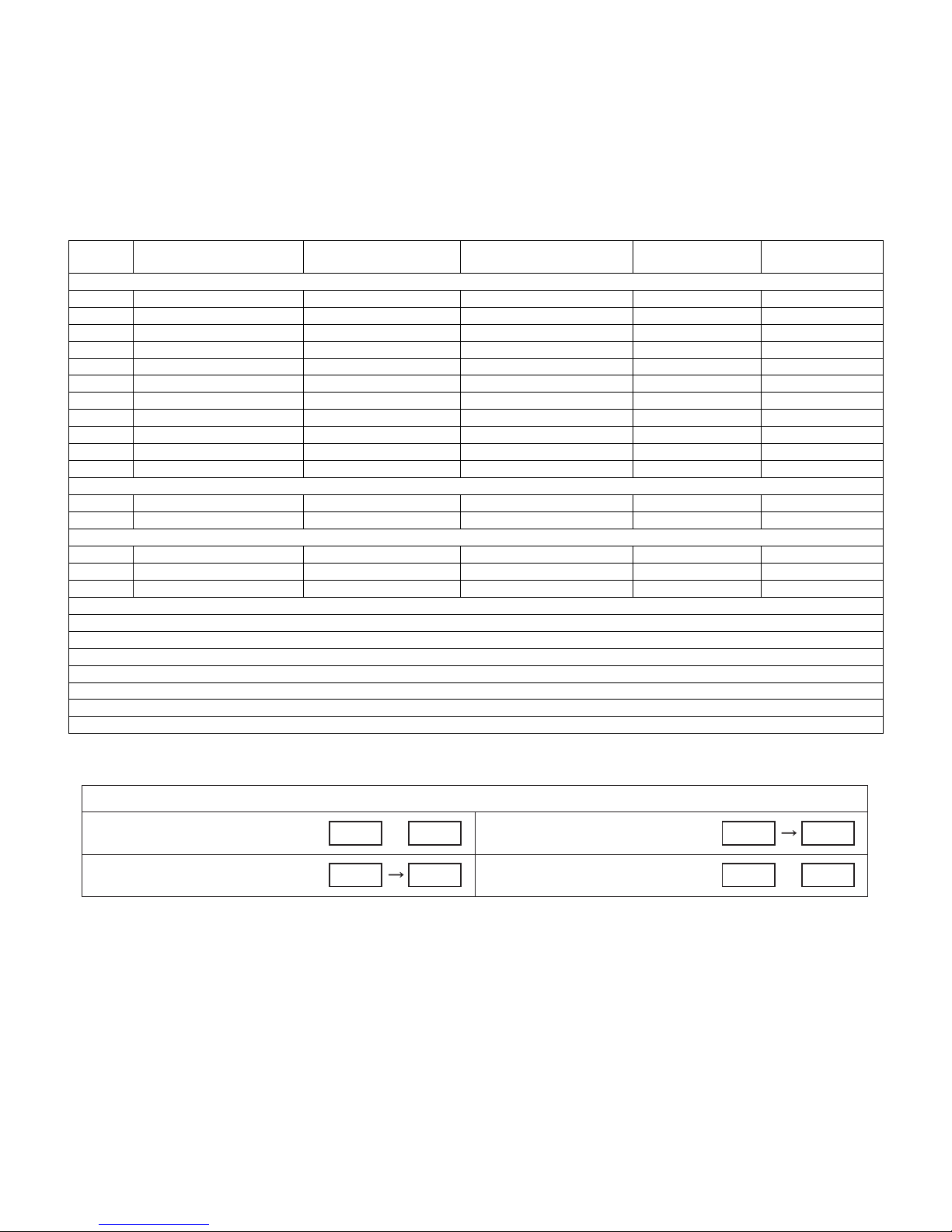
LIST OF CHANGED PARTS (LC-32LE705E/S, LU705E/S, LX705E)
Ref No. Description LC-32LE/LU/LX700E/S
(No. S89B4LC32L700)
PRINTED WIRING BOARD ASSEMBLIES
MAIN Unit DUNTKF306FM01 DKEYDF306FM10 D Changed
KEY Unit DUNTKE266FM18 ← — No change
R/C, LED Unit DUNTKF308FM02 ← — No change
ICON Unit DUNTKF314FM02 ← — No change
POWER Unit RUNTKA619WJQZ ← — No change
LCD Control Unit RUNTK4225TPZU ← — No change
LED5-PWB1 Unit RUNTKA655WJ01 ← — No change
LED5-PWB2 Unit RUNTKA655WJ02 ← — No change
LED8-PWB1 Unit RUNTKA658WJ01 ← — No change
LED8-PWB2 Unit RUNTKA658WJ02 ← — No change
LCD PANEL
32" LCD Panel Module Unit DLCUCA001FM03 ← — No change
MAIN Unit
IC2002 IC RH-iXC786WJN5Q RH-iXC786WJNAQ D Changed
IC3302 IC RH-iXC773WJQZQ RH-iXC951WJQZQ D Changed
CABINET AND MECHANICAL PARTS
Please refer to a Parts list
LCD MODULE Assembly
Please refer to a Parts list
SUPPLIED ACCESSORIES
Please refer to a Parts list
PACKING PARTS (NOT REPLACEMENT ITEM)
Please refer to a Parts list
NOTE: If it is necessary to replace IC8401 and IC3302, replace the main unit.
LC-32LE/LU705E/S/LX705E
(No. SX9D1LC32L705 )
Interchangeability Note
Completely interchangeableA:
Interchangeable from
B:
OLD to NEW
Interchangeability
=
NEWOLD
NEWOLD
Interchangeable from
C:
NEW to OLD
Not interchangeableD:
i
NEW OLD
X
OLDNEW
Page 3

LC-32/40/46LE705E/S, LU705E/S, LX705E, LC-52LE705E/S
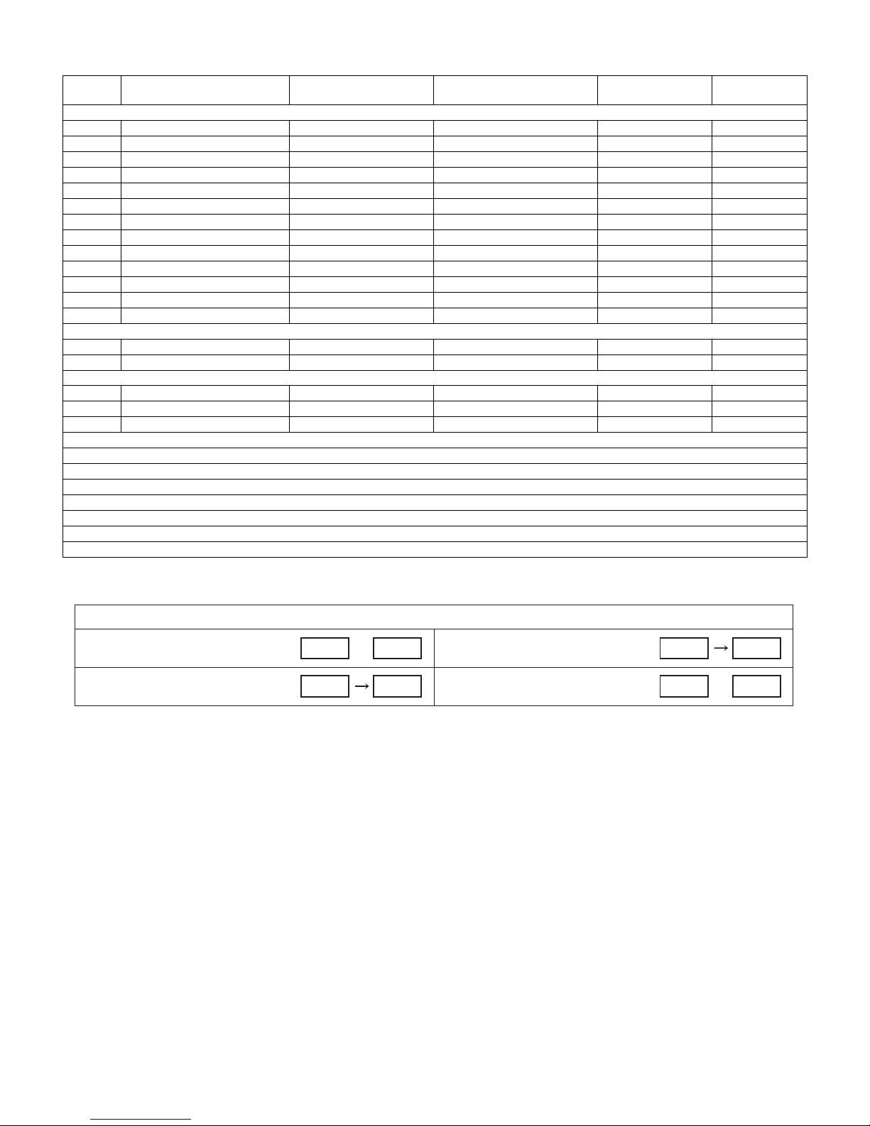
LIST OF CHANGED PARTS (LC-40LE705E/S, LU705E/S, LX705E)
Ref No. Description LC-40LE/LU/LX700E/S
(No. S89B4LC32L700)
PRINTED WIRING BOARD ASSEMBLIES
MAIN Unit DUNTKF306FM01 DKEYDF306FM10 D Changed
KEY Unit DUNTKE266FM18 ← — No change
R/C, LED Unit DUNTKF308FM02 ← — No change
ICON Unit DUNTKF314FM02 ← — No change
POWER Unit RUNTKA642WJQZ ← — No change
LCD Control Unit RUNTK4225TPZU ← — No change
LED5-PWB1 Unit RUNTKA655WJ01 ← — No change
LED5-PWB2 Unit RUNTKA655WJ02 ← — No change
LED6-PWB1 Unit RUNTKA656WJ01 ← — No change
LED6-PWB2 Unit RUNTKA656WJ02 ← — No change
LCD PANEL
40" LCD Panel Module Unit DLCUCA002FM07 ← — No change
MAIN Unit
IC2002 IC RH-iXC786WJN5Q RH-iXC786WJNAQ D Changed
IC3302 IC RH-iXC773WJQZQ RH-iXC951WJQZQ D Changed
CABINET AND MECHANICAL PARTS
Please refer to a Parts list
LCD MODULE Assembly
Please refer to a Parts list
SUPPLIED ACCESSORIES
Please refer to a Parts list
PACKING PARTS (NOT REPLACEMENT ITEM)
Please refer to a Parts list
NOTE: If it is necessary to replace IC8401 and IC3302, replace the main unit.
LC-40LE/LU705E/S/LX705E
(No. SX9D1LC32L705)
Interchangeability Note
Completely interchangeableA:
Interchangeable from
B:
OLD to NEW
Interchangeability
=
NEWOLD
NEWOLD
Interchangeable from
C:
NEW to OLD
Not interchangeableD:
NEW OLD
X
OLDNEW
ii
Page 4
LC-32/40/46LE705E/S, LU705E/S, LX705E, LC-52LE705E/S
LIST OF CHANGED PARTS (LC-46LE705E/S, LU705E/S, LX705E)
Ref No. Description LC-46LE/LU/LX700E/S
(No. S89B4LC32L700)
PRINTED WIRING BOARD ASSEMBLIES
MAIN Unit DUNTKF306FM01 DKEYDF306FM10 D Changed
KEY Unit DUNTKE266FM18 ← — No change
R/C, LED Unit DUNTKF308FM02 ← — No change
ICON Unit DUNTKF314FM02 ← — No change
POWER Unit RUNTKA643WJQZ ← — No change
LCD Control Unit RUNTK4225TPZU ← — No change
LED5-PWB1 Unit RUNTKA655WJ01 ← — No change
LED5-PWB2 Unit RUNTKA655WJ02 ← — No change
LED6-PWB1 Unit RUNTKA656WJ01 ← — No change
LED6-PWB2 Unit RUNTKA656WJ02 ← — No change
LED8-PWB1 Unit RUNTKA658WJ01 ← — No change
LED8-PWB2 Unit RUNTKA658WJ02 ← — No change
LCD PANEL
46" LCD Panel Module Unit DLCUCA003FM07 ← — No change
MAIN Unit
IC2002 IC RH-iXC786WJN5Q RH-iXC786WJNAQ D Changed
IC3302 IC RH-iXC733WJQZQ RH-iXC951WJQZQ D Changed
CABINET AND MECHANICAL PARTS
Please refer to a Parts list
LCD MODULE Assembly
Please refer to a Parts list
SUPPLIED ACCESSORIES
Please refer to a Parts list
PACKING PARTS (NOT REPLACEMENT ITEM)
Please refer to a Parts list
NOTE: If it is necessary to replace IC8401 and IC3302, replace the main unit.
LC-46LE/LU705E/S/LX705E
(No. SX9D1LC32L705)
Interchangeability Note
Completely interchangeableA:
Interchangeable from
B:
OLD to NEW
Interchangeability
=
NEWOLD
NEWOLD
Interchangeable from
C:
NEW to OLD
Not interchangeableD:
NEW OLD
X
OLDNEW
iii
Page 5

LIST OF CHANGED PARTS (LC-52LE705E/S)
LC-32/40/46LE705E/S, LU705E/S, LX705E, LC-52LE705E/S
Ref No. Description LC-52LE700E/S
(No. S89B4LC32L700)
PRINTED WIRING BOARD ASSEMBLIES
MAIN Unit DUNTKF306FM01 DKEYDF306FM10 D Changed
KEY Unit DUNTKE266FM18 ← — No change
R/C, LED Unit DUNTKF308FM02 ← — No change
ICON Unit DUNTKF314FM02 ← — No change
POWER Unit RUNTKA643WJQZ ← — No change
LCD Control Unit RUNTK4225TPZU ← — No change
LED6-PWB1 Unit RUNTKA656WJ01 ← — No change
LED6-PWB2 Unit RUNTKA656WJ02 ← — No change
LED8-PWB1 Unit RUNTKA658WJ01 ← — No change
LED8-PWB2 Unit RUNTKA658WJ02 ← — No change
LCD PANEL
52" LCD Panel Module Unit DLCUCA004FM07 ← — No change
MAIN Unit
IC2002 IC RH-iXC786WJN5Q RH-iXC786WJNAQ D Changed
IC3302 IC RH-iXC733WJQZQ RH-iXC951WJQZQ D Changed
CABINET AND MECHANICAL PARTS
Please refer to a Parts list
LCD MODULE Assembly
Please refer to a Parts list
SUPPLIED ACCESSORIES
Please refer to a Parts list
PACKING PARTS (NOT REPLACEMENT ITEM)
Please refer to a Parts list
NOTE: If it is necessary to replace IC8401 and IC3302, replace the main unit.
LC-52LE705E/S
(No. SX9D1LC32L705)
Interchangeability Note
Completely interchangeableA:
Interchangeable from
B:
OLD to NEW
Interchangeability
=
NEWOLD
NEWOLD
Interchangeable from
C:
NEW to OLD
Not interchangeableD:
NEW OLD
X
OLDNEW
iv
Page 6

LC-32/40/46LE705E/S, LU705E/S, LX705E, LC-52LE705E/S
LC-32LE705E
SAFETY PRECAUTION
Service Manual
IMPORTANT SERVICE SAFETY PRECAUTION
Service work should be performed only by qualified service technicians who are thoroughly familiar with all safety checks and the
servicing guidelines which follow:
WARNING
1. For continued safety, no modification of any circuit should be
attempted.
2. Disconnect AC power before servicing.
CAUTION:
FOR CONTINUED PROTECTION AGAINST A
RISK OF FIRE REPLACE ONLY WITH SAME
TYPE FUSE.
32 inch model: F7001, F7002 (2.5A/250V)
40 inch model: F7001, F7002 (5A/250V)
46/52 inch model: F7001, F7002 (6.3A/250V)
BEFORE RETURNING THE RECEIVER
(Fire & Shock Hazard)
Before returning the receiver to the user, perform the following
safety checks:
3. Inspect all lead dress to make certain that leads are not pinched,
and check that hardware is not lodged between the chassis and
other metal parts in the receiver.
4. Inspect all protective devices such as non-metallic control knobs,
insulation materials, cabinet backs, adjustment and compartment
covers or shields, isolation resistor-capacitor networks, mechanical
insulators, etc.
5. To be sure that no shock hazard exists, check for leakage current in
the following manner.
• Plug the AC cord directly into a 220~240 volt AC outlet.
• Using two clip leads, connect a 1.5k ohm, 10 watt resistor paralleled by a 0.15µF capacitor in series with all exposed metal cabinet
parts and a known earth ground, such as electrical conduit or electrical ground connected to an earth ground.
• Use an AC voltmeter having with 5000 ohm per volt, or higher, sensitivity or measure the AC voltage drop across the resistor.
• Connect the resistor connection to all exposed metal parts having a
return to the chassis (antenna, metal cabinet, screw heads, knobs
and control shafts, escutcheon, etc.) and measure the AC voltage
drop across the resistor.
All checks must be repeated with the AC cord plug connection
reversed. (If necessary, a nonpolarized adaptor plug must be used
only for the purpose of completing these checks.)
Any reading of 1.05 V peak (this corresponds to 0.7 mA peak AC.)
or more is excessive and indicates a potential shock hazard which
must be corrected before returning the monitor to the owner.
DVM
AC SCALE
1.5k ohm
10W
0.15µF
TEST PROBE
///////////////////////////////////////////////////////////////////////////////////////////////////////////////////////////////////////////////////////////////////////////////////////////////////////////////////////////////////////////
SAFETY NOTICE
Many electrical and mechanical parts in LCD color television have
special safety-related characteristics.
These characteristics are often not evident from visual inspection, nor
can protection afforded by them be necessarily increased by using
replacement components rated for higher voltage, wattage, etc.
Replacement parts which have these special safety characteristics are
identified in this manual; electrical components having such features
are identified by “ ” and shaded areas in the Replacement Parts
List and Schematic Diagrams.
///////////////////////////////////////////////////////////////////////////////////////////////////////////////////////////////////////////////////////////////////////////////////////////////////////////////////////////////////////////
TO EXPOSED
METAL PARTS
For continued protection, replacement parts must be identical to those
used in the original circuit.
The use of a substitute replacement parts which do not have the same
safety characteristics as the factory recommended replacement parts
shown in this service manual, may create shock, fire or other hazards.
CONNECT TO
KNOWN EARTH
GROUND
v
Page 7

LC-32/40/46LE705E/S, LU705E/S, LX705E, LC-52LE705E/S
Precautions for using lead-free solder
Employing lead-free solder
• “PWBs” of this model employs lead-free solder. The LF symbol indicates lead-free solder, and is attached on the PWBs and service manuals. The
alphabetical character following LF shows the type of lead-free solder.
Example:
L Fa
Indicates lead-free solder of tin, silver and copper.
Indicates lead-free solder of tin, silver and copper.
L F a/a
Using lead-free wire solder
• When fixing the PWB soldered with the lead-free solder, apply lead-free wire solder. Repairing with conventional lead wire solder may cause damage or accident due to cracks.
As the melting point of lead-free solder (Sn-Ag-Cu) is higher than the lead wire solder by 40 °C, we recommend you to use a dedicated soldering
bit, if you are not familiar with how to obtain lead-free wire solder or soldering bit, contact our service station or service branch in your area.
Soldering
• As the melting point of lead-free solder (Sn-Ag-Cu) is about 220 °C which is higher than the conventional lead solder by 40 °C, and as it has poor
solder wettability, you may be apt to keep the soldering bit in contact with the PWB for extended period of time. However, Since the land may be
peeled off or the maximum heat-resistance temperature of parts may be exceeded, remove the bit from the PWB as soon as you confirm the
steady soldering condition.
Lead-free solder contains more tin, and the end of the soldering bit may be easily corroded. Make sure to turn on and off the power of the bit as
required.
If a different type of solder stays on the tip of the soldering bit, it is alloyed with lead-free solder. Clean the bit after every use of it.
When the tip of the soldering bit is blackened during use, file it with steel wool or fine sandpaper.
• Be careful when replacing parts with polarity indication on the PWB silk.
Lead-free wire solder for servicing
Part No. Description Code
ZHNDAi123250E J φ0.3mm 250g (1roll) BL
ZHNDAi126500E J φ0.6mm 500g (1roll) BK
ZHNDAi12801KE J φ1.0mm 1kg (1roll) BM
vi
Page 8

LC-32/40/46LE705E/S, LU705E/S, LX705E, LC-52LE705E/S
End of life disposal
End of life disposal
A. Information on Disposal for Users (private households)
1. In the European Union
Attention: If you want to dispose of this equipment, please do not use the ordinary dust bin!
Used electrical and electronic equipment must be treated separately and in accordance with legislation that
requires proper treatment, recovery and recycling of used electrical and electronic equipment.
Following the implementation by member states, private households within the EU states may return their
used electrical and electronic equipment to designated collection facilities free of charge*. In some countries*
your local retailer may also take back your old product free of charge if you purchase a similar new one.
Attention: Your
product is marked
with this symbol.
It means that used
electrical and
electronic products
should not be
mixed with general
household waste.
There is a separate
collection system for
these products.
*) Please contact your local authority for further details.
If your used electrical or electronic equipment has batteries or accumulators, please dispose of these
separately beforehand according to local requirements.
By disposing of this product correctly you will help ensure that the waste undergoes the necessary treatment,
recovery and recycling and thus prevent potential negative effects on the environment and human health
which could otherwise arise due to inappropriate waste handling.
2. In other Countries outside the EU
If you wish to discard this product, please contact your local authorities and ask for the correct method of
disposal.
For Switzerland: Used electrical or electronic equipment can be returned free of charge to the dealer, even if
you don’t purchase a new product. Further collection facilities are listed on the homepage of www.swico.ch
or www.sens.ch.
B. Information on Disposal for Business Users
1. In the European Union
If the product is used for business purposes and you want to discard it:
Please contact your SHARP dealer who will inform you about the take-back of the product. You might be
charged for the costs arising from take-back and recycling. Small products (and small amounts) might be
taken back by your local collection facilities.
For Spain: Please contact the established collection system or your local authority for take-back of your used
products.
2. In other Countries outside the EU
If you wish to discard of this product, please contact your local authorities and ask for the correct method of
disposal.
The battery supplied with this product contains traces of Lead.
For EU: The crossed-out wheeled bin implies that used batteries should not be put to the general household
waste! There is a separate collection system for used batteries, to allow proper treatment and recycling in
accordance with legislation. Please contact your local authority for details on the collection and recycling
schemes.
For Switzerland: The used battery is to be returned to the selling point.
For other non-EU countries: Please contact your local authority for correct method of disposal of the used
battery.
vii
Page 9

LC-32LE705E
CHAPTER 1. REMOVING OF MAJOR PARTS
Service Manual
[1] REMOVING OF MAJOR PARTS
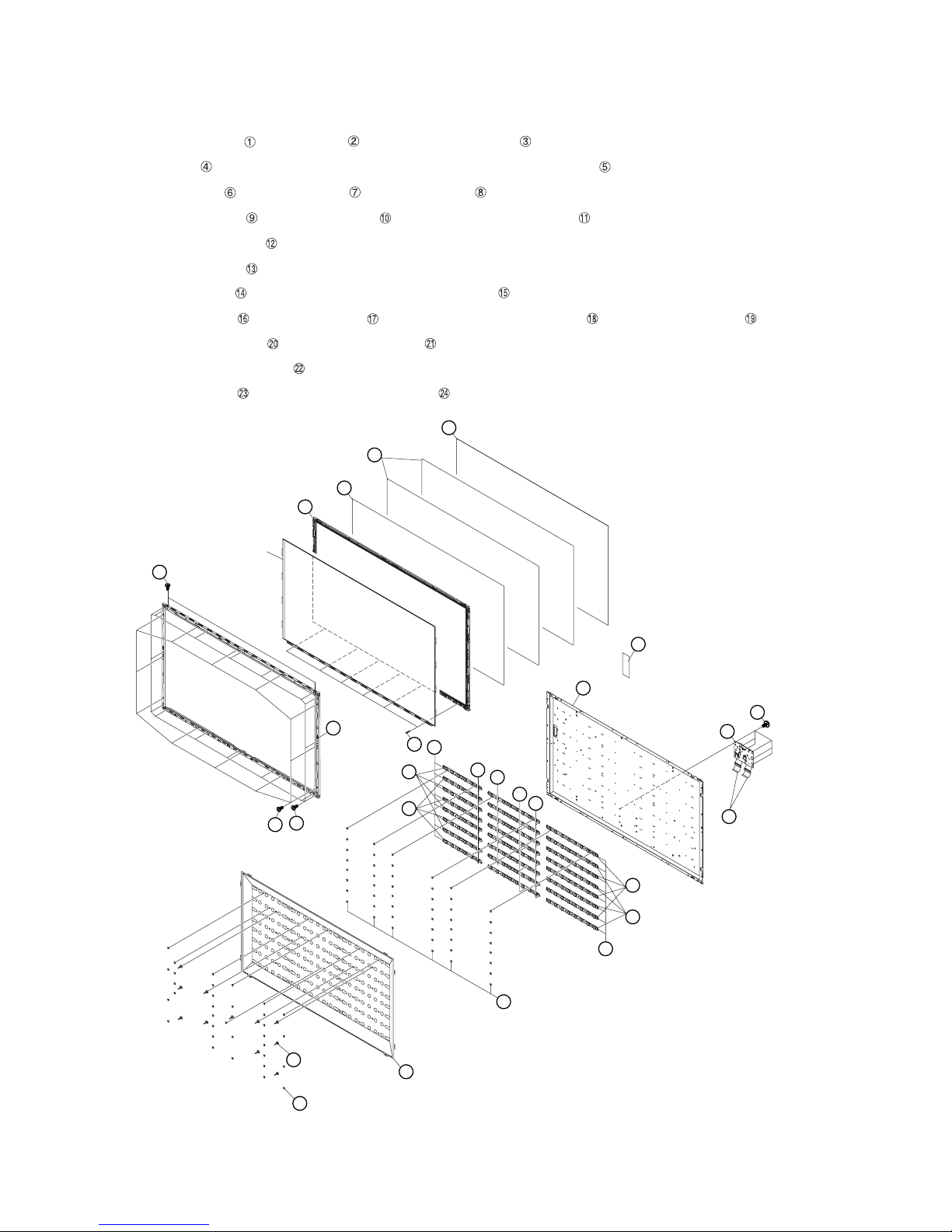
1. Removing of Bezel Ass’y, Panel Chassis Ass’y, Optical Sheet, Lens Sheet, Diffusion Plate, Back Light Chas-
sis and LCD Control Unit (32 inch models).
NOTE: A clean booth is required for repair of the component units and/ or parts (LCD Panel HIRAKI, LED PWB etc.) inside the LCD panel module
unit.
1. Remove the 10 lock screws ,10 lock screws and detach the Bezel Ass’y .
2. Detach the 32” LCD Panel HIRAKI Unit and Panel Chassis Ass’y .
3. Detach the Optical sheet and Lens Sheet and Micro Lens Sheet Diffusion Plate .
4. Remove the 16 Push Rivets and 4 Support Pins and detach the Reflection Sheet .
5. Remove the 32 Push Rivets .
6. Remove the 8 Terminators and 8 connections and detach the 4 LED8 PWB1 Units and 4 LED8 PWB2 Units .
7. Detach the 4 LED5 PWB1 Units and 4 LED5 PWB2 Units .
8. Disconnect the connecting cords from the 8 connectors of the LED5 PWB1/2 Unit.
9. Detach the Back Light Chassis .
10.Detach the 2 Connecting Cord and 2 Ferrite Core .
LC-32/40/46LE705E/S, LU705E/S, LX705E, LC-52LE705E/S
11.Remove the 6 lock screws and detach the LCD Control Unit
5
Optical Sheet
32" LCD
Panel HIRAKI Unit
Bezel Ass'y
3
Panel Chassis
Ass'y
1
Lens Sheet
4
2
Micro Lens Sheet
6
19
18
17
14
7
Diffusion Plate
LCD Control
Unit
Back Light
Chassis
20
8
23
24
Connecting Cord
Ferrite Core
21
22
Support Pin
Push Rivet
9
10
16
15
13
12
Reflection Sheet
11
1 – 1
Page 10
LC-32/40/46LE705E/S, LU705E/S, LX705E, LC-52LE705E/S
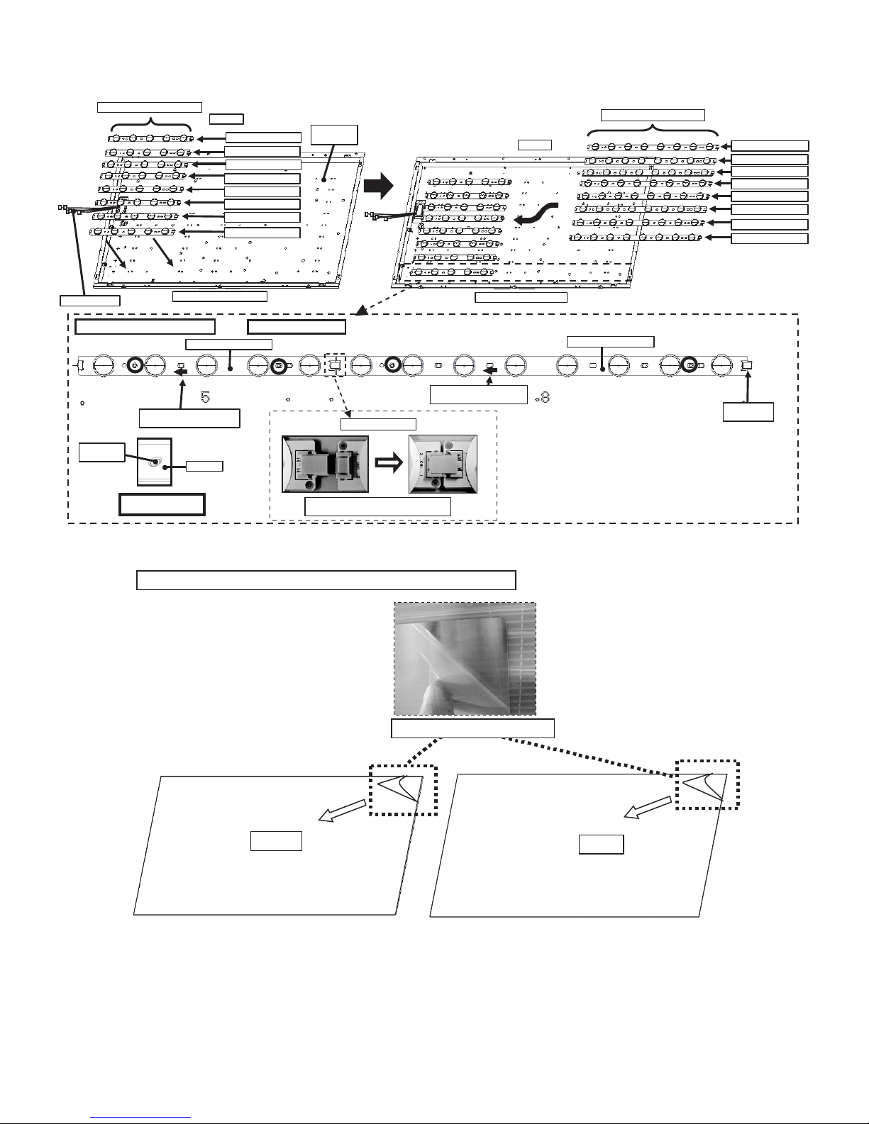
2. Handling notes (32 inch models).
1. Set and connect LED-PWBs.
RUNTKA655WJ01 / WJ02
WIRE HA RNES S
Set and connect LED-PWBs
LED-PWB set direction
(arrow mark to harness side)
Boss o f
BL-CHASSIS
Boss fitting
(showing in blue c ircl es)
Top Sid e
RUNTKA655WJ01
RUNTKA655WJ02
RUNTKA655WJ01
RUNTKA655WJ02
RUNTKA655WJ01
RUNTKA655WJ02
RUNTKA655WJ01
RUNTKA655WJ02
Bottom Side (C-PWB s ide)
RUNTKA655WJ01/02
LED-PWB
INSIDE of
BL-CHASSIS
*Same for other 7 lines.
Insert the connector hor izont ally mutually.
Do not addinadequate power.
Connect LED -PW Bs
Bottom Side (C-PWB side)
LED-PWB set direction
(arrow mark to harnes s s ide)
Top Sid e
RUNTKA658WJ01 / WJ02
RUNTKA658 WJ01 /02
RUNTKA658WJ01
RUNTKA658WJ02
RUNTKA658WJ01
RUNTKA658WJ02
RUNTKA658WJ01
RUNTKA658WJ02
RUNTKA658WJ01
RUNTKA658WJ02
TERMINATOR
is Attach ed
2. Peel off the lamination film of LENS SHEET on the both sides.
Pee l off the lamina tion film of LENS SHEET on the both sides.
FRONT
Pee l off the lamination film.
BACK
1 – 2
Page 11

LC-32/40/46LE705E/S, LU705E/S, LX705E, LC-52LE705E/S
3. Removing of Bezel Ass’y, Panel Chassis Ass’y, Lens Sheet, Diffusion Plate, Back Light Chassis and LCD
Control Unit (40 inch models).
NOTE: A clean booth is required for repair of the component units and/ or parts (LCD Panel HIRAKI, LED PWB etc.) inside the LCD panel module
unit.
1. Remove the 14 lock screws ,12 lock screws and detach the Bezel Ass’y .
2. Remove the 4 Clips and detach the 40” LCD Panel HIRAKI Unit and Panel Chassis Ass’y .
3. Detach the DBEF Sheet and 2 Lens Sheet and Diffusion Plate .
4. Remove the 20 Push Rivets and 8 Support Pins and detach the Reflector Sheet .
5. Detach the 2 Connection Cords .
6. Remove the 42 Push Rivets .
7. Detach the Bush Cap Unit and connecting cords from the 7 Connectors of the LED5-PWB1/2 Unit.
8. Remove the 7 Terminators and 14 connections and detach the 8 LED6-PWB1 Units and 6 LED6-PWB2 Units .
9. Detach the 4 LED5-PWB1 Units and 3 LED5-PWB2 Units .
10.Detach the Back Light Chassis Ass’y .
11.Detach the 2 Ferrite Cores .
12.Remove the 6 lock screws and detach the LCD Control Unit .
Diffusion Plate 8
Lens Sheet 7
Panel Chassis Ass'y
40" LCD Panel HIRAKI Unit
3 Bezel Ass'y
1
DBEF Sheet 6
5
2
14 Bush Cap Unit
22
Back Light Chassis Ass'y
Clip4
15
21
20
17
18
19
17
19
18
16
25LCD Control Unit
2324Ferrite Core
12 Connecting Cord
13
Support Pin10
Reflector Sheet11
Push Rivet9
1 – 3
Page 12
LC-32/40/46LE705E/S, LU705E/S, LX705E, LC-52LE705E/S
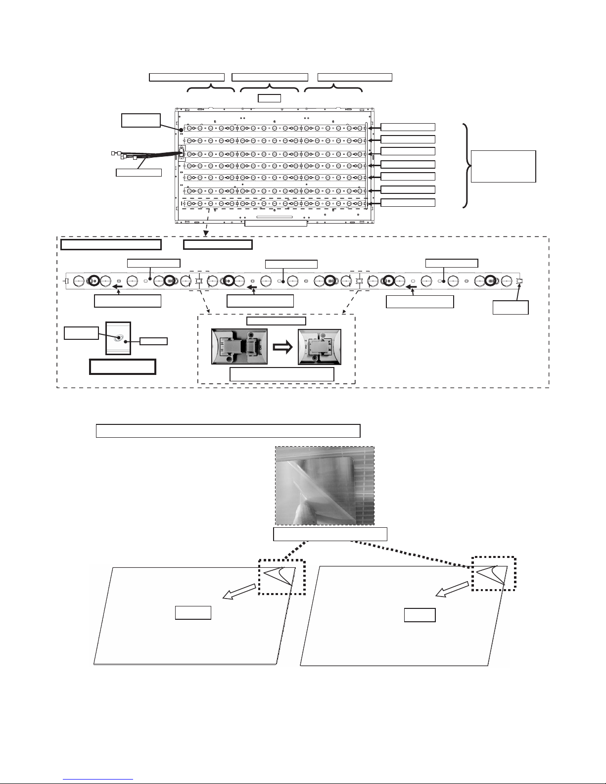
4. Handling notes (40 inch models).
1. Set and connect LED-PWBs.
INSIDE of
BL-CHASSIS
WIRE HARNESS
Set and connect LED-PWBs
RUNTKA655WJ**
LED-PWB set direction
(arrow mark to harness side)
Boss of
BL-CHASSIS
(showing in blue circles)
Boss fitting
LED-PWB
RUNTKA655WJ01 / WJ02
*Same for other lines.
RUNTKA656WJ01 / WJ02 RU NTKA656WJ01 / WJ02
Top Side
Bottom Side (C-PWB side)
RUNTKA656WJ**
LED-PWB set direction
(arrow mark to harness side)
Connect LED-PWBs
Insert the connector horizontally mutually.
Do not add impossible power.
RUNTKA***WJ01
RUNTKA***WJ02
RUNTKA***WJ01
RUNTKA***WJ02
RUNTKA***WJ01
RUNTKA***WJ02
RUNTKA***WJ01
RUNTKA656WJ**
LED-PWB set direction
(arrow mark to harness side)
㧨CAUTION㧪
It being alternated
RUNTKA***WJ01
and RUNTKA***WJ02.
TERMINATOR
is Attached
2. Peel off the lamination film of LENS SHEET on the both sides.
Pee l off the lamina tion film of LENS SHEET on the both sides.
FRONT
Pee l off the lamination film.
BACK
1 – 4
Page 13

LC-32/40/46LE705E/S, LU705E/S, LX705E, LC-52LE705E/S
5. Removing of Bezel Ass’y, Panel Chassis Ass’y, Lens Sheet, Diffusion Plate, Back Light Chassis and LCD
Control Unit (46 inch models).
NOTE: A clean booth is required for repair of the component units and/ or parts (LCD Panel HIRAKI, LED PWB etc.) inside the LCD panel module
unit.
1. Remove the 10 lock screws ,16 lock screws and detach the Bezel Ass’y .
2. Remove the 4 Clips and detach the 46” LCD Panel HIRAKI Unit and Panel Chassis Ass’y .
3. Detach the DBEF Sheet and 2 Lens Sheet and Diffusion Plate .
4. Remove the 23 Push Rivets and 11 Support Pins and detach the Reflector Sheet .
5. Detach the 2 Connection Cords .
6. Remove the 48 Push Rivets .
7. Detach the Bush Cap Unit and connecting cords from the 8 connectors of the LED5-PWB1/2 Unit.
8. Remove the 8 Terminators and 16 connections and detach the 4 LED8-PWB1 Units , 4 LED8-PWB2 Units , 4 LED6-PWB1 Units
and 4 LED6-PWB2 Units .
9. Detach the 4 LED5-PWB1 Units and 4 LED5-PWB2 Units .
10.Detach the Back Light Chassis .
11.Detach the 2 Ferrite Cores .
12.Remove the 6 lock screws and detach the LCD Control Unit .
Diffusion Plate 8
Lens Sheet 7
Panel Chassis Ass'y 5
46" LCD Panel HIRAKI Unit
3 Bezel Ass'y
1
DBEF Sheet 6
2
14 Bush Cap Unit
24 Back Light Chassis
4
Clip
15
22
23
17
20
21
17
18
19
16
27LCD Control Unit
2526Ferrite Core
12 Connecting Cord
Support Pin10
Push Rivet9
13
Reflector Sheet11
1 – 5
Page 14

LC-32/40/46LE705E/S, LU705E/S, LX705E, LC-52LE705E/S
6. Handling notes (46 inch models).
1. Set and connect LED-PWBs.
INSIDE of
BL-CHASSIS
WIRE HARNESS
Set and connect LED-PWBs
RUNTKA655WJ**
LED-PWB set direction
(arrow mark to harness side)
Boss of
BL-CHASSIS
LED-PWB
RUNTKA655WJ01 / WJ02
*Same for other lines.
LED-PWB set direction
(arrow mark to harness side)
Connect LED-PWBs
RUNTKA656WJ01 / WJ02 R UNTKA658WJ01 / WJ02
Top Side
Bottom Side (C-PWB side)
RUNTKA656WJ**
LED-PWB set direction
(arrow mark to harness side)
RUNTKA***WJ01
RUNTKA***WJ02
RUNTKA***WJ01
RUNTKA***WJ02
RUNTKA***WJ01
RUNTKA***WJ02
RUNTKA***WJ01
RUNTKA***WJ02
㧨CAUTION㧪
It being alternated
RUNTKA***WJ01
and RUNTKA***WJ02.
RUNTKA658WJ**
TERMINATOR
is Attached
Boss fitting
(showing in blue circles)
Insert the connector horizontally mutually.
Do not add impossible power.
2. Peel off the lamination film of LENS SHEET on the both sides.
Pee l off the lamina tion film of LENS SHEET on the both sides.
FRONT
Pee l off the lamination film.
BACK
1 – 6
Page 15
LC-32/40/46LE705E/S, LU705E/S, LX705E, LC-52LE705E/S
7. Removing of Bezel Ass’y, Panel Chassis Ass’y, Lens Sheet, Diffusion Plate, Back Light Chassis and LCD
Control Unit (52 inch models).
NOTE: A clean booth is required for repair of the component units and/ or parts (LCD Panel HIRAKI, LED PWB etc.) inside the LCD panel module
unit.
1. Remove the 12 lock screws ,18 lock screws and detach the Bezel Ass’y .
2. Remove the 6 Clips and detach the 52” LCD Panel HIRAKI Unit and Panel Chassis Ass’y .
3. Detach the DBEF Sheet and 2 Lens Sheets and Diffusion Plate .
4. Remove the 33 Push Rivets and 11 Support Pins and detach the Reflection Sheet .
5. Detach the 2 Connection Cords .
6. Remove the 48 Push Rivets .
7. Detach the Bush Cap Unit and connecting cords from the 8 connectors of the LED6-PWB1/2 Unit.
8. Remove the 8 Terminators and 16 connections and detach the 8 LED8-PWB1 Units and 8 LED8-PWB2 Units .
9. Detach the 4 LED6-PWB1 Units and 4 LED6-PWB2 Units .
10.Detach the Back Light Chassis Ass’y .
11.Remove the 6 lock screws and detach the LCD Control Unit .
Diffusion Plate 8
Lens Sheet 7
DBEF Sheet 6
Panel Chassis Ass'y 5
52" LCD Panel HIRAKI Unit
2
14 Bush Cap Unit
22 Back Light Chassis Ass'y
23
3 Bezel Ass'y
2
1
Clip
4
15
20
21
17
18
19
17
16
LCD Control Unit
18
19
24
12 Connecting Cord
Support Pin10
Push Rivet9
13
Reflection Sheet11
1 – 7
Page 16

LC-32/40/46LE705E/S, LU705E/S, LX705E, LC-52LE705E/S
8. Handling notes (52inch models).
1. Set and connect LED-PWBs.
INSIDE of
BL-CHASSIS
WIRE HARNESS
Set and connect LED-PWBs
RUNTKA656WJ**
LED-PWB set direction
(arrow mark to harness side)
Boss of
BL-CHASSIS
LED-PWB
RUNTKA656WJ01 / WJ02
*Same for other lines.
Connect LED-PWBs
RUNTKA658WJ01 / WJ02 RU NTKA658WJ01 / WJ02
Top Side
Bottom Side (C-PWB side)
RUNTKA658WJ**
LED-PWB set direction
(arrow mark to harness side)
RUNTKA***WJ01
RUNTKA***WJ02
RUNTKA***WJ01
RUNTKA***WJ02
RUNTKA***WJ01
RUNTKA***WJ02
RUNTKA***WJ01
RUNTKA***WJ02
RUNTKA658WJ**
LED-PWB set direction
(arrow mark to harness side)
㧨CAUTION㧪
It being alternated
RUNTKA***WJ01
and RUNTKA***WJ02.
TERMINATOR
is Attached
Boss fitting
(showing in blue circles)
Insert the connector horizontally mutually.
Do not add impossible power.
2. Peel off the lamination film of LENS SHEET on the both sides.
Pee l off the lamina tion film of LENS SHEET on the both sides.
FRONT
Pee l off the lamina tion film.
BACK
1 – 8
Page 17

LC-32LE705E
CHAPTER 2. ADJUSTMENT
Service Manual
[1] ADJUSTMENT PROCEDURE
1. Adjustment method after PWB and/or IC replacement due to repair
The unit is set to the optimum at the time of shipment from the factory.
If any value should become improper or any adjustment is necessary due to the part replacement, make an adjustment according to the following procedure.
1. Procure the following units in order to replace the main unit, IC3302 and IC8401.
MAIN UNIT for service: DKEYDF306FM10
NOTE: [Caution when replacing ICs in the main unit (IC501,IC2002)]
The above ICs are EEPROMs storing the EDID data of PC, and Monitor microcomputer.
Before replacing the relevant part, procure the following parts in which the data have been rewritten.
IC501 RH-iXC697WJQZS PC
IC2002 RH-IXC786WJNAQ Monitor microcomputer
NOTE: [Caution when replacing ICs in the main unit (IC8401,IC3302)]
When replacing either IC8401 or IC3302, exchange MAIN units for DKEYDF306FM10
Each part should not be individually exchanged.
IC8401 RH-IXC147WJQZQ Flash
IC3302 RH-IXC951WJQZQ Main CPU
NOTE: HDMI ROM Writing
After replacing IC1504, execute “HDMI EDID WRITE” on the page 5/17
Please execute it after checking MODEL NAME & INCH SIZE. are correct.
The ROM data based on information of MODEL NAME & INCH SIZE
1) Enter the process adjustment mode in AVC.
2) Use the cursor keys ( / ) and P keys ( / ) of R/C to select the item [HDMI EDID WRITE] on the page 5/17.
LC-32/40/46LE705E/S, LU705E/S, LX705E, LC-52LE705E/S
2. After replacing the LCD panel or LCD control/MAIN UNIT, check MODEL NAME in the following procedure.
1) Enter the process adjustment mode in AVC.
2) Use the cursor keys ( / ) and P keys ( / ) of R/C to select the item [MODEL NAME] on the page 17/17.
3) Verify that the Model name is displayed.
4) If the Model name doesn't match, select the values of the Model nmae with the VOL(+/-) keys.
5) After selection in Step 4), press the OK key, and it is completed with OK displayed.
3. After replacing the LCD panel or LCD control UNIT, check PANEL_SIZE in the following procedure.
1) Enter the process adjustment mode in AVC.
2) Use the cursor keys ( / ) and P keys ( / ) of R/C to select the item [PANEL_SIZE] on the page 17/17.
3) Verify that the panel size is displayed.
4) If the size doesn't match, select the values of the panel size with the VOL(+/-) keys.
5) After selection in Step 4), press the OK key, and it is completed with OK displayed.
4. After replacing the LCD panel or LCD control PWB, adjust the VCOM in the following procedure.
1) Enter the process adjustment mode.
2) Use the cursor keys ( / ) and P ( / ) of R/C to select the item [VCOM ADJ] on the page 10/17.
3) Press the OK key to verify that the adjustment pattern is displayed.
4) Use the +/- keys of VOL of R/C to adjust the flicker in the center of the screen to minimum.
5) When the optimal state is achieved in Step 4, press the OK key to turn the pattern to OFF.
2 – 1
Page 18

LC-32/40/46LE705E/S, LU705E/S, LX705E, LC-52LE705E/S
2. List of adjustment process mode menu
The character string in brackets [ ] will appear as a page title in the adjustment process menu header.
Page Line Item Description Remarks (adjustment detail, etc.)
1/17
1 MAIN Version Main software version.
2 BOOT Version BOOT Version.
3 Monitor Version Monitor software version.
4 T-CON/H.264 Version T-CON/H.264 Version.
5 CPLD Version CPLD Version.
6 LED T-CON Version LED T-CON Version.
7 CI+INFO CI+ Key Information.
8 SECURE BOOT MAIN IC is applied to SECURE BOOT.
9 EQ DATA CHECKSUM Audio data checksum.
10 LAMP ERROR Number of termination due to lamp error.
11 MONITOR ERR CAUSE Last error standby cause.
12 NORMAL STANDBY CAUSE Situation that became standby at the end. (Excluding the error)
13 ERROR STANDBY CAUSE Error standby cause.
2/17
1 INDUSTRY INIT Enter Initialization to factory settings execution.
2 INDUSTRY INIT(-Hotel) OFF Initialization to factory settings execution.(Hotel mode is excluded)
3 PUBLIC MODE OFF Hotel mode ON/OFF setting .
4 Center Acutime 5H 0M Main operating hours.
5 RESET OFF Main operating hours reset.
6 Backlight Acutime 19H 35M Backlight operating hours.
7 RESET OFF Backlight operating hours reset.
8 LAMP ERROR RESET OFF Lamp error reset.
9 ADJ PARAM SET Enter ADJ PARAM SET.
10 VIC XPOS 0 X-coordinate setting for VIC READ.
11 VIC YPOS 0 Y-coordinate setting for VIC READ.
12 VIC SIGNAL TYPE MAIN Signal type setting for VIC READ.
13 VIC READ OFF Picture level acquisition function.
3/17
1 RF AGC ADJ Enter RF-AGC auto adjustment execution.
2 TUNER ADJ Enter TUNER auto adjustment execution.
3 PAL+TUNER ADJ Enter PAL TUNER auto adjustment execution.
4 RF AGC 16 RF-AGC auto adjustment execution. (CA-8CH)
5 TUNER ADJ(SMPTE) Enter TUNER auto adjustment execution. (SMPTE)
6 PAL+TUNER ADJ(SMPTE) Enter PAL TUNER auto adjustment execution. (SMPTE)
TUNER ADJ(SMPTE CH57) Enter TUNER auto adjustment execution. (SMPTE CH57)
7 PAL+TUNER ADJ(SMPTE CH57) Enter PAL TUNER auto adjustment execution. (SMPTE CH57)
8 TUNER CONTRAST A_GAIN 14 TUNER signal level adjustment.
9 TUNER CONTRAST D_GAIN 2048 TUNER signal level adjustment.
10 TUNER CONTRAST OFFSET 256 TUNER signal level adjustment.
11 RF AGC READ OFF Reading value of RF-AGC voltage.
4/17
1 PAL ADJ Enter PAL adjustment.
2 SECAM ADJ Enter SECAM adjustment.
3 N358 ADJ Enter N358 adjustment.
4 PAL CONTRAST A_GAIN 14 PAL contrast adjustment.
5 PAL CONTRAST D_GAIN 2048 PAL contrast adjustment.
6 PAL CONTRAST OFFSET 256 PAL contrast adjustment.
7 SECAM CONTRAST A_GAIN 14 SECAM contrast adjustment.
8 SECAM CONTRAST D_GAIN 2048 SECAM contrast adjustment.
9 SECAM CONTRAST OFFSET 256 SECAM contrast adjustment.
10 N358 CONTRAST A_GAIN 14 N358 contrast adjustment.
11 N358 CONTRAST D_GAIN 2048 N358 contrast adjustment.
12 N358 CONTRAST OFFSET 256 N358 contrast adjustment.
5/17
1 HDMI CEC TEST Enter HDMI CEC test.
2 INSPECT USB TERM Enter Reading inspection of USB memory terminal .
3 HDMI EDID WRITE Enter HDMI EDID WRITING.
4 MONIDATA READ[TEMP/OPC] OFF MONITOR Temperature/ OPC Acquisition tool.
5 CAUSE RESET Enter Reset of standby cause .
(Level appears in green on the upper right)
2 – 2
Page 19

LC-32LE705E
CHAPTER 3. MAJOR IC INFORMATIONS
Service Manual
[1] MAJOR IC INFORMATIONS
1. DESCRIPTION OF MAJOR ICs
Ref No. Name Part Code Description
[MAIN UNIT]
LC-32/40/46LE705E/S, LU705E/S, LX705E, LC-52LE705E/S
IC8401 RH-iXC721WJQZQ Flash This IC is 1GB NAND flash memory.
IC3302 RH-iXC951WJQZQ Main CPU This IC is Video Processor & MAIN CPU.
IC2002 RH-iXC786WJQZQ
IC3501/
3502
for service
(RH-iXC786WJNAQ)
RH-iXC790WJQZQ DDR This IC is 512Mb DDR2 SDRAM.
UCOM The monitor microprocessor is intended to communicate with the main CPU and to
This IC stores the software data that processes the system of TV such as the
graphic processing, the LCD controls, and backlights etc.
In this IC, the decode processing and the video signal processing are done.
Moreover, OSD is generated here and added to a picture signal.
operate the system. It also controls power of the entire system.
This IC operates as a memory of IC3302 (Video Processor). ***
3 – 1
Page 20

LC-32/40/46LE705E/S, LU705E/S, LX705E, LC-52LE705E/S
— MEMO —
3 – 2
Page 21

LC-32/40/46LE705E/S, LU705E/S, LX705E, LC-52LE705E/S
4 – 1
LC-32LE705E
Service Manual
CHAPTER 4. OVERALL WIRING/SYSTEM BLOCK DIAGRAM
[1] OVERALL WIRING DIAGRAM
1
23
1097654
8
J
A
B
C
D
E
F
G
H
I
1311 191816151412 17
OVERALL WIRING DIAGRAM (LC-32LE705E/S, LU705E/S, LX705E)
MAIN UNIT for service
(DKEYDF306FM)
QCNW-K269WJQZ
Page 22

LC-32/40/46LE705E/S, LU705E/S, LX705E, LC-52LE705E/S
4 – 2
1
23
1097654
8
J
A
B
C
D
E
F
G
H
I
1311 191816151412 17
OVERALL WIRING DIAGRAM (LC-40LE705E/S, LU705E/S, LX705E)
MAIN UNIT for service
(DKEYDF306FM)
QCNW-K271WJQZ
RUNTKA642WJQZ
Page 23

LC-32/40/46LE705E/S, LU705E/S, LX705E, LC-52LE705E/S
4 – 3
1
23
1097654
8
J
A
B
C
D
E
F
G
H
I
1311 191816151412 17
OVERALL WIRING DIAGRAM (LC-46LE705E/S, LU705E/S, LX705E)
MAIN UNIT for service
(DKEYDF306FM)
QCNW-K273WJQZ
RUNTKA643WJQZ
Page 24

LC-32/40/46LE705E/S, LU705E/S, LX705E, LC-52LE705E/S
4 – 4
1
23
1097654
8
J
A
B
C
D
E
F
G
H
I
1311 191816151412 17
OVERALL WIRING DIAGRAM (LC-52LE705E/S)
MAIN UNIT for service
(DKEYDF306FM)
RUNTKA643WJQZ
Page 25

LC-32/40/46LE705E/S, LU705E/S, LX705E, LC-52LE705E/S
4 – 5
[2] SYSTEM BLOCK DIAGRAM
1
23
1097654
8
J
A
B
C
D
E
F
G
H
I
1311 191816151412 17
SYSTEM BLOCK DIAGRAM (LC-32LE705E/S, LU705E/S, LX705E)
OFL1
LR_OUT
SDA.SCL(400Hz)
UR+13.5V
Spliter
IXC790WJ
IC506
SC2_Y/C
PDD[0:7]
HDMI_4
PNL_EN
CNVss
PS_ON
EXT5
USB
CPU1.2V
S153
LVDS_OUT
PM_REQ,CBOOTS
BU+3.3V
TVPOW
(10pin)
1920x1080
LED_OPC
SC1505
27MHz
DDC_4
SPDIF_OUT
AC_DET
MONITOR_MICON
IC3502
R
EXT6
BU+3.3V
RS_BUF_CNT
HV_MODE
SPK_OUT_L/R
RS232CTxRx
SC503
20MHz
CIController
OPT_OUT
TA2+/-,TB2+/-,TC2+/-,TCLK2+/-,TD2+/-,TE2+/-
RC
Disclete
(MINI_PLUG)
(12pin)
DET_SYNC
AV_LINK_O
SC2_IN_L/R
J50
BR24C21F
DDC_1
S155
SIF
Disclete
ANALOG_RGB
RESET
POWR_LED
J504
S+13.5V
Disclete
TUNER_OUT_L/R
SLOWSW2
INTERFACE)
COMP_YPbPr
D3.3V
SP_L
IC2002
BU3.3V
SC2_Y/C
DDC_2
HDMI-3
PC_RGB
RMC101
LCD_EN
LCD_CONTROLLER
TA1+/-,TB1+/-,TC1+/-,TCLK1+/-,TD1+/-,TE1+/-,
CH-DOWN
AUDIO_OUTPUT
TU1101
IXC790WJ
RXD/TXD
MUTE
SW_TMDS_D2
SC1_IN_L/R
RS-232C
IC8401
G/B
IR
D1.05V
RA(P102)
HDMI_2
POW13V
IC2601
EXT4
1066Mbit
YPbPr/LR
SW.
IXC147WJQZQ
LR_OUT
LP(P2602)
CPU_UARXD0_RS
S24C508J
AMP13V
PNL_IC2_EN
LED_OPC
PE
R/C,LED UNIT
M3221EIP-1Y
SC502
(5pin)
BU+5V
SW
7WH126FU
CH-UP
SC501
KEY2
GPFSV51V
LB(CN7008)
D3.3V
(12pin)
IC507
CI_CEB,CI_RB
KM(P151)
IC1504
ANT_POW
MONITOR_L/R
OPC
D_POW
(COMMON
20MHz
IR_PASS
S+8V
SC1_CVBS/Y
X3302
SW.
PC_H/Vsync
LNB_SHORT
3.3V
IC3302
TC7SH00U
SM_POW
(4pin)
RGB
IC2007
EXT1(CVBS/YC/RGB)
IR_SW.
TU_CVBS_OUT_MUTE
POWER
DIGITAL
INPUT
EEPROM
POWER_SUPPLY
PD(P9601)
SC1502
FLASH
MUTE
OPC
PD(CN7003)
MUTE
VOL-DOWN
POWER_UNIT
M24C64WN
BU+3.3V
EXT8
EXT2(CVBS/YC)
VCOM_WP
OPC
STB
PM_REQ,CBOOTS
OPC
TUNEROUT
OFL1
KEY1
RGB
KEY2
TUNER_OUT
HP_PLUG
USB
IC2701
IFAGC
RXD/TXD_CPU
W_PROT_M
MONITOR_OUT_L/R
P2701
MUTE_A_ALL
Disclete
SW_TMDS_D0P/N
LAMP_ERR
AV_LINK
CVBSBYPASS
LCD_PANEL
DET_SYNC
BU+5V
N_SRESET
D520
TUNER_CVBS_SEL
EXE_LED1
MONITOR_L/R
COMP_YPbPr
SIF
X2002
DET_POW1_13V
IC504
PNL_ROM_EN
SC1FSW
(PC)
KEY1
KM(P2002)
PNL+12V
FS/FB
CVBS_IN_L/R
J501
POW_SW
CVBS/LR
IC4405
PC_RGB
D_IFIN P/N
IC8455
MAIN_SYSTEM
CNVss
I2C1_SCL
ERR_PNL
CEC_O12
TUNER
S154
CNVss
IC503
MM1507XN
MAINUNIT
EXT3(COMP/AUD)
STB
IC8452
IC508
AUDIO_OUT
T7SET08
SW_TMDS_D1
TS_CI_OUT
(4pin)
IC501
HDMI-2
SLOWSW1
EXT4/6
AV_LINK_I
S151
D1.8V
TUNER_SDA/SCL
SP_R
EXE_LED
MUTE
PNL_WP
27MHz
D3.3V
PL(CN7004)
SII9287
(15pin)
KEYUNIT
CVBS_YU_OUT
AHC1G08W
TS_CPU_OUT
SC2_CVBS/Y
AV_OUT
etc.
IXC951WJQZQ
PC/HDMI_L/R
SC1FSW
SC4401
(9pin)
DET
HC2G66DP
FS/
IC2008
YDA148QZ
RA(P2003)
GSP
CVBS/LR
USB_DP/N
SPK_OUT
SW_TMDS_CLKP/N
I2C1_SDA
IXC786WJ
MM1756AU
MUTE
CIRCUIT
HP_L/R
OPTOUT
VOL-UP
HDMI-SW
D_POW
X4401
SC1_Y/C
TUNER_CVBS
COMP_IN_L/R
UCOM_RST
TH2001
DigitalAV decode
PC_H/Vsync
R/C
D_IFIN P/N
IC8454
IFAGC
LB(P9602)
VCOM_SCL/SDA
CI
AHC1G08W
SENSOR
S80927NM
CIEN,CIDET
CPU_UATXD0_RS
CVBS_MONI_OUT
POWG_LED
PL(P4804)
SC2_CVBS_Y
AV_LINK
TMDS_Rx/I2C_SINK
J3301
DET_POW2_PNL12V
512Mbit
D103
RECEVER
(41pin)
TUNER_OUT_L/R
MM1506XN
HDMI2/PC
(10pin)
TUNER_CVBS
OUTPUT(AUDIO)
EEPROM
RS_BUF_CNT
BUSY/CE/EPM/SCLK
IC2004
CEC_LINE
LW(SC4801)
AUDIO(R/L)
IC2001
LINEREG
SC1_CVBS_Y
IC2009
LNB_SHORT
EXE_LED
1066Mbit
CI_CNT_RESET
MONITOROUT
GCK
(4pin)
D5V
LP(P4803)
(41pin)
S156
DDR2
D3.3V
EXT7
AV_LINK
LCX157FT
IC3301
SLOWSW1
RGB
VON
SC2_IN_L/R
LED_G
IC101
X2001
PC/HDMI_L/R
CPU_TXD_UCOM
LW(P2601)
MUTE_A_ALL
SC1_Y/C
HP
TS_CI_IN
RESET
COMP_IN_L/R
QSTEMP
STBY_POW
(9pin)
DDR2
J503/503
RXD/TXD_DBCG
BD6538G
DET_POW3_D3V3
TS_CPU_IN
CVBS/LR
CEC_I12
(15pin)
CVBS_IN
HP_L/R
ANT_5V_SW
SC1_IN_L/R
BACK-UP_SYSTEM
SLOWSW2
MENU
MT8295
AC_DET
SW
OPT_OUT
HDMI_1
RGB
OPC+3.3V
LCDPANEL UNIT
S157
EEPROM
SPAMP
MUX
IC3501
N_CPU_RST
HDMI-1
S152
J505
SP
SC1503
D102
LED_R
CVBS__IN
CI_D[7:0]/CI_A[14:0]
CVBS_IN_L/R
SC1_V_OUT
N_SRESET
SC2_V_OUT
EXT8
HDMI-4
SC1501
IC1102
LV4053FT
IF_DEMIX
DVB-CSEL
27MHz
Demodulator
X1101
STV0297E
IC1106
DVB-C
FE_RST
DDC_3
HDMI_3
ICONUNIT
IM(P101)
(2pin)
D5V
Q2002
SW.
RN4901
ILL_LED
IM(P201)
(2pin)
SDA1.SCL1
LAMP_ERR
CPU_UATXD2_UCOM
CPU_UARXD2_UCOM
CPU_RXD_UCOM
GCK
GSP
PNL_POW
PNL_POW
PNL_12V
LA1(CN7006)
(12pin)
LA2(CN7007)
(6pin)
T-CONUNIT
PS_ON
STBY_CONV.
156V
NOISE_FILTER
BU+5V
MAIN_CONV.
13V
13V
AC_INLET
BU5V
PFC
CONTROL
156V
AC-DET
3.3V
SCL/SDABL
(3pin)
SA(CN7001)
VSYNC
OFL
U7701
IR2E59
SCL/SDABL
LEDDRIVER
BL_ON
V13CTL
STB
ERROR
LCMXO1200
HSYNC
Reset
CONTROLER
U7702
LEDDRIVER
SCLC/SIN/SOUT
(CN7603)
(CN7604) (CN7601/7602)
Spliter
HC2G66DP
IC9611
IC4401/2/3
Buffer
LCX244FT
DVBC
CEC_LINE
BU+3.3V
OPT+3.3V
Page 26

LC-32/40/46LE705E/S, LU705E/S, LX705E, LC-52LE705E/S
4 – 6
1
23
1097654
8
J
A
B
C
D
E
F
G
H
I
1311 191816151412 17
SYSTEM BLOCK DIAGRAM (LC-40LE705E/S, LU705E/S, LX705E)
1920x1080
LCD_CONTROLLER
LB(CN7605)
(12pin)
3.3V
(4pin)
PD(CN7501)
POWER_UNIT
LCD_PANEL
PNL+12V
PL(CN7503)
(15pin)
PL(P4804)
(41pin)
LW(SC4801)
(4pin)
LP(P4803)
(9pin)
LCDPANEL UNIT
PNL_12V
LA1(CN7606)
(10pin)
LA2(CN7607)
(10pin)
T-CONUNIT
PS_ON
STBY_CONV.
204V
NOISE_FILTER
BU+5V
MAIN_CONV.
13V
13V
AC_INLET
BU5V
PFC
CONTROL
204V
AC-DET
3.3V
(3pin)
SA(CN7002)
VSYNC
OFL
U7801
IR2E59
SCL/SDABL
LEDDRIVER
BL_ON
V13CTL
STB
ERROR
LCMXO1200
HSYNC
Reset
CONTROLER
U7802
LEDDRIVER
SCLC/SIN/SOUT
(CN7603)
(CN7604) (CN7601/7602)
SW_TMDS_D0P/N
KEYUNIT
SC1505
PC_H/Vsync
PC_RGB
SPDIF_OUT
GCK
LNB_SHORT
RXD/TXD
J503/503
RGB
MT8295
DDR2
27MHz
RS-232C
(PC)
OPT_OUT
1066Mbit
MENU
LAMP_ERR
EXT4/6
IC1106
J505
EXT4
LED_OPC
(5pin)
J501
TUNER_OUT
20MHz
HC2G66DP
DVB-CSEL
MONITOROUT
S151
CH-DOWN
CPU_UARXD2_UCOM
FS/
IFAGC
SPK_OUT_L/R
DET_SYNC
EXE_LED
(2pin)
MAINUNIT
OPT+3.3V
BU+3.3V
RXD/TXD_CPU
TS_CI_OUT
TUNER_OUT_L/R
IC2701
D1.8V
X2002
IC2001
COMP_YPbPr
CVBS_IN_L/R
HDMI_3
PNL_POW
PNL_POW
IC2004
LCD_EN
ANALOG_RGB
SW.
MM1756AU
SPK_OUT
IC3302
USB
SC2_CVBS_Y
RS_BUF_CNT
STBY_POW
KM(P151)
HP
BUSY/CE/EPM/SCLK
UCOM_RST
GSP
Buffer
SC4401
D_POW
LED_OPC
SP_L
OUTPUT(AUDIO)
SC1_IN_L/R
(9pin)
STV0297E
COMP_YPbPr
D3.3V
DVB-C
YPbPr/LR
ILL_LED
(15pin)
AV_LINK
EXT6
(2pin)
MAIN_SYSTEM
LINEREG
SLOWSW1
TUNER_OUT_L/R
LNB_SHORT
(12pin)
J504
IC504
CVBS/LR
R/C,LED UNIT
AUDIO_OUT
VOL-UP
SENSOR
X1101
EXT7
CPU_TXD_UCOM
D1.05V
CVBS_IN_L/R
CI_CNT_RESET
IC508
LP(P2602)
DDR2
S156
(41pin)
PS_ON
EXT3(COMP/AUD)
COMP_IN_L/R
CIController
RESET
MUTE
SC1_IN_L/R
20MHz
IC501
AHC1G08W
INTERFACE)
RGB
IC8452
AV_LINK_O
AV_LINK_I
USB_DP/N
D5V
PD(P9601)
HV_MODE
SM_POW
CEC_LINE
SW.
PDD[0:7]
TU1101
TMDS_Rx/I2C_SINK
BU+5V
LR_OUT
GSP
BU3.3V
CPU_UATXD2_UCOM
S155
POWER_SUPPLY
IC8401
MUTE
OFL1
BU+3.3V
Spliter
27MHz
IR_SW.
D102
SC1502
HDMI_4
LED_G
IXC790WJ
SW_TMDS_D1
IC3301
DigitalAV decode
DET_SYNC
RESET
COMP_IN_L/R
CPU1.2V
MONITOR_L/R
I2C1_SDA
S153
HDMI-1
CPU_RXD_UCOM
FLASH
AUDIO_OUTPUT
SP
QSTEMP
TU_CVBS_OUT_MUTE
SC2_Y/C
IC2002
IXC147WJQZQ
HC2G66DP
RGB
LVDS_OUT
RA(P102)
SC1_V_OUT
N_CPU_RST
OPTOUT
OPC
MUTE_A_ALL
DDC_2
TUNER_CVBS_SEL
TH2001
S152
IC2601
S24C508J
MUTE_A_ALL
HDMI2/PC
AUDIO(R/L)
CIRCUIT
SC501
BU+5V
EEPROM
KEY1
PNL_IC2_EN
IC9611
PE
BU+3.3V
J50
SW_TMDS_D2
CIEN,CIDET
PC/HDMI_L/R
SW_TMDS_CLKP/N
LAMP_ERR
Q2002
TUNER
D520
IXC951WJQZQ
EXT8
LW(P2601)
KEY2
RMC101
CPU_UARXD0_RS
RS232CTxRx
SC1503
MONITOR_L/R
D_POW
S+8V
CEC_O12
EEPROM
LV4053FT
HP_PLUG
IXC786WJ
FE_RST
SPAMP
EXE_LED1
1066Mbit
IC506
POWER
DDC_1
CNVss
VCOM_SCL/SDA
CVBS_MONI_OUT
STB
N_SRESET
IC507
IC3501
SLOWSW2
TUNEROUT
(10pin)
SC1FSW
IC8454
AV_LINK
UR+13.5V
TA2+/-,TB2+/-,TC2+/-,TCLK2+/-,TD2+/-,TE2+/-
CVBS/LR
GPFSV51V
TUNER_SDA/SCL
PM_REQ,CBOOTS
X4401
DDC_4
D103
OPT_OUT
SC1_CVBS_Y
IC4405
PC_RGB
SC1_Y/C
N_SRESET
D3.3V
SCL/SDABL
(MINI_PLUG)
KM(P2002)
POW_SW
TS_CI_IN
MUTE
TUNER_CVBS
TS_CPU_OUT
PNL_EN
D3.3V
HP_L/R
CVBS_IN
PC/HDMI_L/R
TC7SH00U
MUTE
S80927NM
SC502
AV_LINK
SII9287
CVBSBYPASS
SP_R
PM_REQ,CBOOTS
RC
IC2009
KEY2
EXT5
OPC
IC1504
Disclete
IF_DEMIX
CI_CEB,CI_RB
HDMI_1
SW.
SLOWSW2
CVBS/LR
CVBS_YU_OUT
IC101
SC2_V_OUT
D_IFIN P/N
IC4401/2/3
R/C
(4pin)
USB
CNVss
OPC
W_PROT_M
Demodulator
SW
M3221EIP-1Y
PNL_WP
IC2007
Disclete
TUNER_CVBS
SLOWSW1
EEPROM
IC8455
RGB
SDA.SCL(400Hz)
EXT8
GCK
IC3502
SC1501
ANT_5V_SW
(10pin)
AC_DET
27MHz
IM(P201)
RA(P2003)
SC1_Y/C
AC_DET
X2001
MUTE
BD6538G
S154
YDA148QZ
ERR_PNL
HDMI-2
TA1+/-,TB1+/-,TC1+/-,TCLK1+/-,TD1+/-,TE1+/-,
S+13.5V
etc.
LCX157FT
AV_OUT
DET_POW3_D3V3
MM1506XN
OFL1
CNVss
SC2_IN_L/R
EXT2(CVBS/YC)
D3.3V
R
SW
CEC_I12SIF
STB
HDMI-3
T7SET08
X3302
7WH126FU
IFAGC
POW13V
DVBC
CEC_LINE
CI_D[7:0]/CI_A[14:0]
RECEVER
TS_CPU_IN
S157
RN4901
HP_L/R
SC1FSW
SDA1.SCL1
DET_POW2_PNL12V
SIF
Disclete
HDMI-SW
D_IFIN P/N
IM(P101)
EXT1(CVBS/YC/RGB)
Disclete
VOL-DOWN
PNL_ROM_EN
MUX
LCX244FT
ANT_POW
D5V
PC_H/Vsync
POWG_LED
SC2_IN_L/R
BACK-UP_SYSTEM
EXE_LED
IXC790WJ
MONITOR_OUT_L/R
CPU_UATXD0_RS
FS/FB
Spliter
IC503
VCOM_WP
J3301
IR_PASS
LB(P9602)
CI
DDC_3
POWR_LED
KEY1
BR24C21F
TVPOW
OPC
CVBS__IN
DIGITAL
BU+3.3V
MONITOR_MICON
I2C1_SCL
P2701
(COMMON
RS_BUF_CNT
VON
OPC+3.3V
SC2_CVBS/Y
IC1102
512Mbit
HDMI-4
G/B
LR_OUT
DET_POW1_13V
IC2008
AHC1G08W
M24C64WN
CH-UP
IR
SC2_Y/C
SC503
AMP13V
SC1_CVBS/Y
DET
LED_R
MM1507XN
HDMI_2
INPUT
RXD/TXD_DBCG
ICONUNIT
Page 27

LC-32/40/46LE705E/S, LU705E/S, LX705E, LC-52LE705E/S
4 – 7
1
23
1097654
8
J
A
B
C
D
E
F
G
H
I
1311 191816151412 17
SYSTEM BLOCK DIAGRAM (LC-46LE705E/S, LU705E/S, LX705E, LC-52LE705E/S)
1920x1080
LCD_CONTROLLER
LB(CN7605)
(12pin)
3.3V
(4pin)
PD(CN7001)
POWER_UNIT
LCD_PANEL
PNL+12V
PL(CN7003)
(15pin)
PL(P4804)
(41pin)
LW(SC4801)
(4pin)
LP(P4803)
(9pin)
LCDPANEL UNIT
PNL_12V
LA2(CN7007)
(10pin)
LA3(CN7008)
(6pin)
T-CONUNIT
PS_ON
STBY_CONV.
228V
NOISE_FILTER
BU+5V
MAIN_CONV.
13V
13V
AC_INLET
BU5V
PFC
CONTROL
228V
AC-DET
3.3V
(3pin)
SA(CN7002)
VSYNC
OFL
U7801
IR2E59
SCL/SDABL
LEDDRIVER
BL_ON
V13CTL
STB
ERROR
LCMXO1200
HSYNC
Reset
CONTROLER
U7802
LEDDRIVER
(10pin)
LA1(CN7606)
SCLC/SIN/SOUT
U7803
IR2E59
LEDDRIVER
(CN7604)
(CN7603)
(CN7601/7602)
LCX244FT
IFAGC
S153
CVBS_MONI_OUT
W_PROT_M
IXC951WJQZQ
SC2_Y/C
Disclete
YDA148QZ
TS_CPU_IN
IC507
X3302
DET_POW2_PNL12V
LINEREG
KM(P2002)
(2pin)
CPU_TXD_UCOM
RS-232C
VCOM_SCL/SDA
J504
BU+3.3V
HP
SC503
AC_DET
J3301
CPU_RXD_UCOM
RA(P2003)
RESET
DET
UR+13.5V
DDC_3
J503/503
OFL1
AHC1G08W
CVBS_IN
D5V
ANT_5V_SW
MONITOR_MICON
RGB
CH-UP
YPbPr/LR
CI
OPC
MONITOROUT
R/C
SLOWSW2
IC2008
TUNEROUT
VOL-UP
IC508
RXD/TXD_DBCG
27MHz
MONITOR_OUT_L/R
RA(P102)
CEC_I12
GSP
SC1_IN_L/R
TA1+/-,TB1+/-,TC1+/-,TCLK1+/-,TD1+/-,TE1+/-,
DET_POW1_13V
SLOWSW1
IC8452
CVBS/LR
FS/
CVBS/LR
MAINUNIT
COMP_IN_L/R
IC8454
IC101
BU+3.3V
COMP_IN_L/R
IC1102
(15pin)
POWER_SUPPLY
USB
DDR2
IC504
EXT4/6
T7SET08
HDMI2/PC
SCL/SDABL
EXT1(CVBS/YC/RGB)
HDMI_3
SC1_Y/C
GSP
SENSOR
SP
SW_TMDS_D1
CPU_UARXD0_RS
Buffer
BU+5V
IC3501
COMP_YPbPr
HP_L/R
D1.05V
Spliter
MUX
(5pin)
IC3502
DVB-CSEL
Q2002
RGB
OPC
CI_CEB,CI_RB
R
Spliter
PC/HDMI_L/R
AV_LINK
BACK-UP_SYSTEM
VON
TUNER_CVBS
MM1506XN
SW.
EXT6
MUTE
D3.3V
GCK
ICONUNIT
LNB_SHORT
LCX157FT
IXC790WJ
BU3.3V
HDMI-SW
IC2001
LED_G
PC_RGB
7WH126FU
IC4405
IR_SW.
IC2701
TUNER_OUT
BU+3.3V
FS/FB
ILL_LED
RS_BUF_CNT
SC2_IN_L/R
SW_TMDS_CLKP/N
512Mbit
UCOM_RST
IC4401/2/3
EXT7
RGB
SC2_CVBS_Y
CNVss
SW.
CPU1.2V
HDMI_1
SLOWSW1
D5V
KEY1
SC1501
27MHz
RS_BUF_CNT
20MHz
IM(P201)
EXE_LED
IC2009
EXE_LED
SC1503
EXT5
HDMI_2
TS_CPU_OUT
N_CPU_RST
D3.3V
TUNER_SDA/SCL
SC502
P2701
SDA.SCL(400Hz)
RN4901
R/C,LED UNIT
S155
IC3301
PC_RGB
CEC_LINE
IF_DEMIX
HP_PLUG
D_POW
POW13V
MM1507XN
PE
CVBS_IN_L/R
S154
Demodulator
PNL_IC2_EN
STV0297E
AC_DET
SW_TMDS_D0P/N
SC2_Y/C
OPC
1066Mbit
CVBS__IN
CNVss
X4401
IXC786WJ
TUNER
X2002
SDA1.SCL1
AUDIO(R/L)
D_IFIN P/N
CIController
(2pin)
D102
D1.8V
HDMI-3
PD(P9601)
IFAGC
CPU_UARXD2_UCOM
OUTPUT(AUDIO)
PNL_ROM_EN
SC1FSW
SC1_Y/C
MONITOR_L/R
CPU_UATXD2_UCOM
DDC_1
PS_ON
MM1756AU
(10pin)
MUTE
RMC101
QSTEMP
AMP13V
IC2007
LV4053FT
BUSY/CE/EPM/SCLK
IM(P101)
CEC_O12
LED_OPC
S24C508J
LAMP_ERR
EEPROM
RXD/TXD
X1101
IR
PNL_EN
SM_POW
PDD[0:7]
I2C1_SCL
FLASH
PC/HDMI_L/R
GPFSV51V
D_POW
KM(P151)
IC2004
KEY2
MAIN_SYSTEM
SIF
IC2002
HDMI_4
GCK
IC2601
CVBSBYPASS
SC1502
HC2G66DP
SP_R
M3221EIP-1Y
COMP_YPbPr
27MHz
ERR_PNL
DDC_2
DIGITAL
LED_R
VOL-DOWN
IXC147WJQZQ
HV_MODE
HDMI-1
CPU_UATXD0_RS
IC9611
AV_LINK_I
OPT_OUT
PM_REQ,CBOOTS
OFL1
STBY_POW
MUTE
CI_D[7:0]/CI_A[14:0]
(PC)
SPK_OUT_L/R
DVBC
AHC1G08W
POWER
D103
LAMP_ERR
N_SRESET
S152
CNVss
USB
OPC
S157
AV_LINK
LCD_EN
IC1504
(COMMON
IC506
DigitalAV decode
SC1505
RGB
EXT2(CVBS/YC)
BD6538G
HDMI-4
TH2001
SC2_CVBS/Y
IC1106
MT8295
TS_CI_OUT
IC8455
CH-DOWN
CIRCUIT
MUTE_A_ALL
SII9287
TUNER_CVBS
Disclete
HP_L/R
CVBS_IN_L/R
TU_CVBS_OUT_MUTE
TUNER_CVBS_SEL
D520
CIEN,CIDET
N_SRESET
OPT+3.3V
SIF
DET_POW3_D3V3
AUDIO_OUTPUT
SC1_V_OUT
SPDIF_OUT
(MINI_PLUG)
EXE_LED1
20MHz
SPK_OUT
INPUT
TMDS_Rx/I2C_SINK
Disclete
AV_LINK
LED_OPC
MUTE_A_ALL
OPC+3.3V
SP_L
SC2_V_OUT
J501
SW_TMDS_D2
STB
DET_SYNC
Disclete
RC
CI_CNT_RESET
AV_OUT
SC1FSW
X2001
EXT4
OPT_OUT
BU+5V
RECEVER
POWR_LED
TC7SH00U
EEPROM
PNL_POW
SC501
MUTE
RXD/TXD_CPU
SW
ANT_POW
M24C64WN
TS_CI_IN
DDC_4
CEC_LINE
MUTE
EXT8
SC2_IN_L/R
S+8V
TA2+/-,TB2+/-,TC2+/-,TCLK2+/-,TD2+/-,TE2+/-
1066Mbit
S151
SW
EXT8
VCOM_WP
DVB-C
J50
(4pin)
DET_SYNC
LW(P2601)
OPTOUT
BU+3.3V
INTERFACE)
S80927NM
STB
AUDIO_OUT
etc.
CVBS_YU_OUT
SC1_CVBS/Y
POW_SW
IC3302
ANALOG_RGB
G/B
TUNER_OUT_L/R
AV_LINK_O
KEY1
IC501
MONITOR_L/R
EXT3(COMP/AUD)
(10pin)
I2C1_SDA
SC4401
PC_H/Vsync
D3.3V
IR_PASS
IC8401
LR_OUT
KEY2
USB_DP/N
KEYUNIT
DDR2
PNL_WP
TVPOW
J505
RESET
SLOWSW2
BR24C21F
LP(P2602)
(12pin)
IXC790WJ
EEPROM
SC1_IN_L/R
LB(P9602)
LNB_SHORT
RS232CTxRx
(9pin)
POWG_LED
TUNER_OUT_L/R
PM_REQ,CBOOTS
D_IFIN P/N
S156
S+13.5V
SC1_CVBS_Y
LVDS_OUT
IC503
HDMI-2
MENU
FE_RST
(41pin)
HC2G66DP
PNL_POW
CVBS/LR
D3.3V
SW.
SPAMP
TU1101
LR_OUT
PC_H/Vsync
Page 28

LC-32/40/46LE705E/S, LU705E/S, LX705E, LC-52LE705E/S
5 – 1
LC-32LE705E
Service Manual
CHAPTER 5. PRINTED WIRING BOARD ASSEMBLIES
[1] MAIN Unit
MAIN Unit (Side A)
123456789
A
B
C
D
E
F
G
H
I
J
10 11 12 13 14 15 16 17 18 19 20 21
Page 29

LC-32/40/46LE705E/S, LU705E/S, LX705E, LC-52LE705E/S
5 – 2
MAIN Unit (Chip Side A)
SG1530
C8455
SG1531
SG1532
C8456
C8457
C8458
L3301
C1507
C1120
C1123
C1124
R600
Q1509
C1125
R601
R602
R603
D1103
D1104
R604
C1129
R605
R606
R1103
R607
R1104
C8468
R1105
C8469
R1106
C1130
R1108
IC1101
C1131
IC1102
C1132
IC1103
C1133
IC1104
C8470
R610
Q9601
C8471
R611
Q9602
IC1106
R612
Q9604
C1138
R1110
R614
R1111
R615
R1112
Q8472
R616
R1113
R617
R1114
C1524
R618
D8454
R1115
C1525
R619
D8455
R1116
D8456
R8452
R8453
D8457
C1140
R8454
C1141
R8455
D1505
R8457
IC8451
R621
IC8452
R622
C1147
R623
R1120
C1148
R624
IC8454
C1531
IC8455
R1509
R625
IC1501
R1122
R626
IC1502
IC1503
IC1504
C1534
C4414
D1510
R1125
R629
R1126
IC1506
R1127
R1128
C9621
R8465
C9622
R8466
D1517
C9623
R8467
R1514
R630
R8468
C9625
R631
C1155
R8469
R1516
R632
C1156
R633
R1518
R1130
R634
R1519
C1159
R635
R1132
R636
R9603
R1133
R637
R9604
C4424
R8470
R638
C4425
R639
R1136
R1137
R8473
R1138
IC9601
C9631
R1139
R4401
X2001
IC9602
R4402
X2002
R8476
IC9603
R4403
R8477
C9634
D9610
IC9604
R1524
R640
R8478
C1165
IC9605
D9611
R641
P2701
R8479
D9612
IC9606
R1526
R4406
R642
D9613
C9637
R1527
C1167
IC9607
R643
IC9608
R1140
C9638
R644
IC9609
C9639
R647
R648
R649
IC4405
R8482
R1147
R8483
IC9610
C9640
R1148
R8484
R8485
IC9611
R9619
R1149
C9641
R8486
C1173
R4414
R1536
R4416
R1537
C9647
R4417
R9620
R9621
R1539
R4419
C9649
R1154
R9628 C9651
R9629
R1541
R1543
C9654
C9655
C9657
R9630
C2704
C9659
R9631
C2705
C2706
Q2702
Q2703
C2707
C2708
C2709
R9638
C9660
R1550
C9661
R4431R4432
C9663
R4433
C9664
C2710
C2711
C2712
C2713
R1558
R9640
C2714
R1559
R4439
C2715
C2716
C2717
C2718
C2719
R4440
R1560
R1561
R4442R4443
R1564
R4444
C2720
R1565
C2721C2722
C2723
R4448
C2724
VA3301
C2725
D2701
VA3302
D2702
C2726
D2703
C2727
C2728
D2704
P3301
D2705
C2729
R2701
D2706
R4450
R2704
FB2611
R4451
R2705
R4452
FB2612
R2706
R2707
FB2614
C2730
R2708
R2709
C2731
IC2701
C2732
FB2617
C2733
R4458
C2734
R4459
C2735 C2736
C2737
C2738
R2710
C2739
Q505
Q506
Q507Q508
R2714
R4461
R2715
FB2621
Q509
R4462
R1582
R2716
FB2622
R4463
R2717
FB2623
R1584
R2718
FB2624
C8501
R2719
FB2625
C8502
FB2626
C8503
FB2627
FB2628
FB2629
L2601
C8506
L2602L2603
C8508
R2720
L2604
C3301
C8509
L501
R2721
L2605
C3302
L502
R2722
L2606
L503
R2723
R9678
C3304
L504
FB2630
R2724
FB2631
R2725
C3306
C3308
C3309
R2729
C3503
C3310
R2730
R9686
R9687
FL501
FL502
FL503
FL504
FL505
FL506
FL507FL508
FL509
D8501
D8502
D8503
D8504
C3321
R8501
R8502
C3323
R8503
R8504
FL510
D3301
FL511
R8505
C3326
R8506
FL512
D3303
R8507
FL513
FL514
R8508
R8509
FL515
IC8501
VA501
D3306
FL516
VA502
FL517
VA503
D3308
VA504
D3309
VA505
R3305
VA506
R3306
VA507
R3308
VA508
R3309
C3331
IC3301
VA509
R8511
IC3302
R8512
IC3303
R8513
R8514
D3311
R3501
X1101
R8515
R3502
R8516
R8517
D3314
R8518
VA510
D3315
R8519
D3316
R3506
R3312
D3317
R3507
R3313
R3508
R3314
D3319
IC3501
FB501
IC3502
FB502
R3316
FB503
R8520
FB504
FB505
R8521
R8522
FB506
R8523
FB507
D3320
FB508
R3511
D3321
FB509
R3512
D3323
C3347
D3324
D3325
R3321 R3322
D3326
R3323
D3328
FB510
D3329
FB511
R501
R3325
R502
FB512
R503
FB513
R504
FB514
FB515
R505
R506
FB516
R507
FB517
R508
FB518
FB519
R509
FB520
R510
R511
FB521
R512
FB522
R513
FB524
R514
R515
R516
FB526
R517
R518
FB528
R519
FB529
C3367
P2001
R3342
P2002
P2003
R3343
FB530
R3344
R520
R3345
X4401
R521
FB531
R3346
R522
FB532
R3347
FB533
R523
R3348
C3370
R524
FB534
R3349
C3371
FB535
R525
C3372
R526
R527
C3374
R528
R529
C3376
C3377
R3350
C3378
C3379
R3351
L1102
R3353
R3354
R530
R3355
R531
R3356
SC8452
R532
R3357
R533
R3358
R534
R3359
FB9601
R535
SC1501
C3382
FB9602
R536
SC1502
FB9603
C3383
R537
SC1503
FB9604
C3384
SC1504
R538
C3385
FB9605
SC1505
LUG9601
R539
FB9606
LUG9602
FB9607
LUG9603
R3360
LUG9604
R3361
LUG9605
C501
R3362
C502
LUG9607
R3363
C503
R3364
LUG9608
R540
R541
P2601
R3366
P2602
Q2002
R542
R3367
P2603
R543
C507
Q2003
C3390
R3368
C508
R544
Q2004
C3391
FL3301
L1501
R545
C2009
C3392
FL3302
L1502
R546
C3393
R547
L1503
C3394
R548
L1504
C3395
R549
C3396
C3397
R3370
C3398
C510
R3371
C3399
C511
C2011
R3372
C2014
R550
R551
C2015
R552
R3377
C517
R553
R3378
R554
R3379
R555
C519
R556
R557
R558
R559
R3380
C520
R3381
C521
R3382
L9602
C522
R3383
C523
R3384
L9604
R560
C524
L9605
R561
C2025
C525
C2602
L9606
C526
C2026
R562
C527
D2003
R563
R564
C528
R565 C529
R566
R567
R568
D2008
R569
C530C531
C2031
C532
IC2002
C2032
C533
C2033
C534
R570
C2034
R3395
C535
R571
C2035
C536
C2036
C537
R574
C538
IC2008
C539
R575
C2039
R576
R2012
R578
R579
R2016
R2017
C540
TH2001
R2019
C541
TH2002
R580
R581
C546
R582
R583
C547
C548
R584
R2021
C549
R585
R586
R587
R588
R589
FB2701
FB2702
FB2703
R2604
C550
R2028
FB2704
C551
R2605
FB2705
C552
R2606
FB2706
C553
R2607
FB2707
R590
C554
FB2708
IC2601
R591
C555R592
C556
R593
C557
C558
R594
C559
R595
R596
R597
R598
R2034
R599
R2035
R2036
C560
C561
D501
R2039
C562
D502
C563
D503
D504
C564
D505
C565
C566
D506
D507
C567
C568
D508
D509
R2041
C569
R2042
R2043
R2045
D510
C570
X8501
D511
C571
D512
C572
C573
D513
D514
C574
D515
L2701
C575
C576
L2702
L2703
C3400
L2704
C3401
R2051
X3302
C3402
C3403
R2053
C3404
C3405
C3406
R2632
C3407
R2634
IC501
D521
C581
R2059
C582
D522
IC503
C583
R2638
IC504
C585
IC505
D526
D527
IC507
C587
C588
IC508
C589
R2062
R2063
R2064
C590
D530
C591
C592
C593
IC8401
FB3301
IC8402
FB3302
R2073
C1101
C1102
C1103
C1105
C1106
C1107
C1108
Q1104
C1109
Q1106 Q1107
SG1525
SG1526 SG1527
R2088
SG1528
P9601
SG1529
P9602
C1113
P9603
C1114
C1115
L8501
C1116
L8502
C1117
123456789
A
B
C
D
E
F
G
H
I
J
10 11 12 13 14 15 16 17 18 19 20 21
Page 30

LC-32/40/46LE705E/S, LU705E/S, LX705E, LC-52LE705E/S
5 – 3
MAIN Unit (Side B)
123456789
A
B
C
D
E
F
G
H
I
J
10 11 12 13 14 15 16 17 18 19 20 21
Page 31

LC-32/40/46LE705E/S, LU705E/S, LX705E, LC-52LE705E/S
5 – 4
MAIN Unit (Chip Side B)
C1118
C1508
Q1504
C1509
Q1505
Q1506
Q1507
C8460
Q1508
D1101
C8461
D1102
C1126
C8462
C1127
C1128
C1510
D1105
C1511
R1101 R1102
C1512
C1513
C1514
R608
C1515
R609
C1516
C1517
R1107
C1518
C1519
C9601
R1109
C9602
C9603
C9604
C1134
C1135
C9605
C9606
C1136
C9607
C1137
IC1107
R613
C9608
C1520
C1139
C9609
C1521
C4401
C1522
C4402
C4403
Q9607
C1523
Q9608
C4404
Q9609
Q4401
R8451
D1501
C4405
D1502
C1526
C4406
R1117
C1527
C4407
D1503
C9610
D1504
R1118
C4408
C1528
R1119
C9611
C1529
R1501
C4409
C9612
C1142
R8456
D1506
R1502
C9613
D1507
C1143
R1503
C9614
C1144
R1504
Q9610
R8458
D1508
R620
C9615
D1509
C1145
R8459
R1505
C1146
C9616
R1506
R1507
C9617
C9618
C1530
C4410
R1508
C9619
C1149
R1121
C4411
C4412
R1123
R627
C4413
R1124
R628
C4415
R8461
IC1505
D1511
D1512
C4416
R8462
C4417
R8463 R8464
C4418
C1150
C9620
R1510
R1129
C4419
R1511
C1151
D1516
C1152
R1512
C1153
R1513
C9624
C1154
D9601
D9602
C9626
C9627
D9603
R1517
C1157
C9628
D9604
C4420
C1158
R9601
C9629
R1131
D9605
C4421
R9602
D9606
C4422
D9607
C4423
R1134
D9608
R9605
R1135
D9609
D1521
C4426
R8472
D1522
R9607
D1523
C9630
C1160
R8474
D1524
C1161
D1525
D1526
C9632
R1522
C9633
D1527
D1528
R4404
D1529
C9635
R4405
C1166
C9636
R4407
D9614
R9610
R1528
R4408
D9615
R1529
IC4401
R645
R1141
R4409
D9616
R9612
R1142
R646
IC4402
R1143
R9613
IC4403
R9614
R1144
D1530
R8480
IC4404
R9615
R1145
R8481
R9616
R1146
R9617
R1530
R4410
R1531
C1171
R4411
R4412
C1172
C9642
R1532
C9643
R4413
R8487
C9644
R4415
C9645
R1535
C9646
C9648
R1538
R4418
R1151
R1152
R9622
R1153
R9623
R9624
R9625
FB2001
R9626
FB2002
FB2003
C9650
R4420
R1540
FB2004
R4421
FB2005
C9652
R1542
FB2006
R4422
FB2007
R4423
R1544
R4424
FB2008
R1545
FB2009
C2701
R4425
C9656
R1546
C2702
R4426
R1547
R4427
C2703
C9658
R4428
R1548
R1549
R4429
Q2701
R9632
R9633
R9634
FB2010
Q2704
R9635
FB2011
R9636
FB2012
R9637
FB2013
R4430
FB2014
R1551
R9639
C9662
R1552
R1553
R1554
R4434
R1555
C9665
R4435
C9666
R1556
R4436
R1557
R4437
R4438
R9641
R9642
R9643
R9644
R9645R9646
R9647
R9648
R9649
R4441
R4445
R4446R4447
R9650
R4449
R9651
R9652
R9656
R2702
R9657
R2703
D2707
R9658
FB2610
R4453
FB2613
R4454
R4455
FB2616
R4456
R4457
Q501 Q502Q503
R9664
Q504
R9665
R2711
R9666
R2712
R2713
R4460
R9669
R4464
R4465
R4466
R4467
R9670
C8504
R4468
R9671
R4469
C8505
R9672
R9673
C8507
R9675
R9676
R9677
C3303
C3305
R9679
R2726
R2727
C3307
R2728
C8510
C8511
C8512
C3501
R9681
C3502
R9682
R9683
C3504
C3505
C3311
R9685
C3312
C3506
C3313
C3507
C3314
C3508
C3315
C3509
C3316
C3317
C3318
C3319
C3510
C3511
C3512
C3513
C3320
C3514
C3515
C3322
C3516
C3517
C3324
C3518
C3519
C3325
C3327
D3304
C3328
R3301
C3329
D3305
R3302
R3303
D3307
R3304
C3520
C3521
C3522
C3523
R3307
C3330
C3524
R8510
C3525
D3501
C3332
C3333
C3334
D3310
C3335
C3336
D3312
D3313
R3503
C3337
R3310
R3504
C3338
R3311
R3505
C3339
D3318
R3509
R3315
R3317
C3340
R3318
C3341
R3319
C3342
C3343
C3344
R3510
C3345
C3346
D3322
R3320
C3348
C3349
D3327
R3324
R3326
R3327
R3328
C3350
R3329
C3351
C3352
FB1102
C3353
D3330
C3354
C3355
C3356
C3357
C3358
C3359
R3332
R3333
R3334
R3335
R3336
R3337
FB523
C3360
C3361
FB525
C3362
C3363
FB527
C3364
C3365
C3366
C3368
R3340
R3341
C3369
FB1504
FB1506
FB1507
FB1508
FB1509
C3373
C3375
FB1510
L1101
R3352
FB1512
L1103
L1104
L1106
L1107
C3380
L1108
C3381
C3386
C3387
FB9608
C3388
C3389
FB4401
C2001
FB4402
C2002
FB4403
C2003
FB4404
C2004
FB4405
R3365
Q2001
C2005
C2006
C2007
C2008
R3369
Q2005
Q2006
FL3303
FL3304
C2010
C2012
R3373
C2013
R3374
FL3501
R3375
R3376
FL3502
C2016
C2017
C2018
C2019
C2020
C2021
C2022
C2023
C2024
D2001
C2027
C2028
R3389
C2029
R2001
R2002
Q2603
D2007
R2003
R2004
D2009
R2005
R2006
R2007
R3390
R2008
C2030
IC2001
R2009
R3391
IC2003
IC2004
IC2005
R3396
R572
IC2006
R573
IC2007
C2037
R2010
C2038
R2011
IC2009
R577
R2013
R2014
R2015
IC2010
R2018
C542
C543
C544
C545
R2020
R2022
R2023
R2024
R2025
R2601
R2026
R2602
R2603
R2027
R2029
R2608
R2030
R2031
R2032
R2033
R2611
R2612
R2613
R2037
R2038
R2615
R2616
R2617
R2618
R2619
R2040
R2620
R2044
R2621
R2046
R2047
R2623
R2048
R2624
R2049
R2625
R2626
R2627
R2628
R2629
D516
D517
C577
D518
C578
R2050
X3301
D519
C579
R2052
R2630
R2054
R2631
R2056
R2633
R2057
C3408
R2058
C580
R2635
R2636
R2637
D523
C584
D524
R2639
D525
C586
IC506
D528
R2060
D529
IC509
R2061
R2640
FB8501
R2065
R2641
FB8502
R2066
R2642
FB8503
R2067
R2643
R2068
R2069
FB3303
FB3304
R2070
FB3305
R2071
FB3306
R2072
FB3307
FB3308
R2074
R2075
R2076
R2077
R2078
R2079
C1104
Q1101
Q1102
Q1103
Q1105
R2084
R2085
R2086R2087
C1110
C1111
C1112
C8451
C8452
C8453
123456789
A
B
C
D
E
F
G
H
I
J
10 11 12 13 14 15 16 17 18 19 20 21
Page 32

LC-32/40/46LE705E/S, LU705E/S, LX705E, LC-52LE705E/S
6 – 1
LC-32LE705E
Service Manual
CHAPTER 6. SCHEMATIC DIAGRAM
[1] DESCRIPTION OF SCHEMATIC DIAGRAM
1. VOLTAGE MEASUREMENT CONDITION:
1) The voltages at test points are measured on exclusive AC adaptor and the stable supply voltage of AC 220-240V. Signals are fed by a color bar signal generator for servicing purpose and the above voltages are measured with a 20k ohm/V tester.
2. INDICATION OF RESISTOR & CAPACITOR:
RESISTOR
1) The unit of resistance "Ω" is omitted.
(K=kΩ=1000Ω, M=MΩ).
2) All resistors are ± 5%, unless otherwise noted.
(K= ± 10%, F= ± 1%, D= ± 0.5%)
3) All resistors are 1/16W, unless otherwise noted.
CAPACITOR
1) All capacitors are µF, unless otherwise noted.
(P=pF=µµF).
2) All capacitors are 50V, unless otherwise noted.
CAUTION:
This circuit diagram is original one, therefore there may be a slight
difference from yours.
SAFETY NOTES:
1) DISCONNECT THE AC PLUG FROM THE AC OUTLET
BEFORE REPLACING PARTS.
2) SEMICONDUCTOR HEAT SINKS SHOULD BE REGARDED AS
POTENTIAL SHOCK HAZARDS WHEN THE CHASSIS IS
OPERATING.
IMPORTANT SAFETY NOTICE:
PARTS MARKED WITH " " ( ) ARE IMPORTANT
FOR MAINTAINING THE SAFETY OF THE SET. BE SURE TO
REPLACE THESE PARTS WITH SPECIFIED ONES FOR MAINTAINING THE SAFETY AND PERFORMANCE OF THE SET.
Page 33

LC-32/40/46LE705E/S, LU705E/S, LX705E, LC-52LE705E/S
6 – 2
[2] SCHEMATIC DIAGRAM
1. MAIN Unit-4
123456789
A
B
C
D
E
F
G
H
I
J
10 11 12 13 14 15 16 17 18 19 20 21
Page 34

LC-32/40/46LE705E/S, LU705E/S, LX705E, LC-52LE705E/S
6 – 3
2. MAIN Unit-11
1
23
1097654
8
J
A
B
C
D
E
F
G
H
I
1311 191816151412 17
Page 35

PartsGuide
LC-32/40/46LE705E/S, LU705E/S, LX705E, LC-52LE705E/S
PARTS GUIDE
No. SX9D1LC32L705
LCD COLOUR TELEVISION
LC-32LE705E/S, LC-32LU705E/S
LC-32LX705E
LC-40LE705E/S, LC-40LU705E/S
Note:
The reference numbers on the PWB
are arranged in alphabetical order.
[1] PRINTED WIRING BOARD
ASSEMBLIES
[2] LCD PANEL
[3] DKEYDF306FM10 (MAIN Unit)
[4] CABINET AND MECHANICAL
PARTS (LC-32LE/LU/LX705)
[5] LCD PANEL MODULE UNIT
(LC-32LE/LU/LX705)
[6] CABINET AND MECHANICAL
PARTS (LC-40LE/LU/LX705)
[7] LCD PANEL MODULE UNIT
(LC-40LE/LU/LX705)
MODELS
LC-40LX705E
LC-46LE705E/S, LC-46LU705E/S
LC-46LX705E
LC-52LE705E/S
CONTENTS
[9] LCD PANEL MODULE UNIT
(LC-46LE/LU/LX705)
[10] CABINET AND MECHANICAL
PARTS (LC-52LE705)
[11] LCD PANEL MODULE UNIT
(LC-52LE705)
[12] SUPPLIED ACCESSORIES
[13] PACKING PARTS
(NOT REPLACEMENT ITEM)
(LC-32/40LE/LU/LX705)
[14] PACKING PARTS
(NOT REPLACEMENT ITEM)
(LC-46LE/LU/LX705, LC-52LE705)
[8] CABINET AND MECHANICAL
PARTS (LC-46LE/LU/LX705)
Parts marked with " " are important for maintaining the safety of the set. Be sure to replace these
parts with specified ones for maintaining the safety and performance of the set.
[15] SERVICE JIGS
(USE FOR SERVICING)
This document has been published to be used
for after sales service only.
The contents are subject to change without notice.
Page 36

LC-32/40/46LE705E/S, LU705E/S, LX705E, LC-52LE705E/S
NO. PARTS CODE
PRICE
RANK
[1] PRINTED WIRING BOARD ASSEMBLIES
N DKEYDF306FM10 CD N P MAIN Unit (DUNTKF306FM10)
N DUNTKE266FM18 AR P KEY Unit
N DUNTKF308FM02 AL P R/C, LED Unit
N DUNTKF314FM02 AL P ICON Unit
!
!
!
N RUNTKA619WJQZ BS P POWER Unit (for 32 inch model)
N RUNTKA642WJQZ P POWER Unit (for 40 inch model)
N RUNTKA643WJQZ P POWER Unit (for 46/52 inch model)
N RUNTK4225TPZU BR N P LCD Control Unit
N RUNTKA655WJ01 AU N J LED5-PWB1 Unit (for 32/40/46 inch model)
N RUNTKA655WJ02 AU N J LED5-PWB2 Unit (for 32/40/46 inch model)
N RUNTKA656WJ01 AW N J LED6-PWB1 Unit (for 40/46/52 inch model)
N RUNTKA656WJ02 AW N J LED6-PWB2 Unit (for 40/46/52 inch model)
N RUNTKA658WJ01 AX N J LED8-PWB1 Unit (for 32/46/52 inch model)
N RUNTKA658WJ02 AX N J LED8-PWB2 Unit (for 32/46/52 inch model)
[2] LCD PANEL
N DLCUCA001FM03 DL P 32"LCD Panel Module Unit (for 32 inch model)
N DLCUCA002FM07 DS N P 40"LCD Panel Module Unit (for 40 inch model)
N DLCUCA003FM07 DR N P 46"LCD Panel Module Unit (for 46 inch model)
N DLCUCA004FM07 DU N P 52"LCD Panel Module Unit (for 52 inch model)
[3] DKEYDF306FM10 (MAIN Unit)
IC2002 RH-iXC786WJNAQ J IC R5F364A6NFB (Monitor Micon)
IC8401 Not Available - - IC K9F1208U0C-PCB0 *PWB replacement item
IC3302 Not Available - - IC MT5391DWCJ (MAIN CPU) *PWB replacement item
NEW
MARK
PAR T
DELIVERY
DESCRIPTION
2
Page 37

LC-32/40/46LE705E/S, LU705E/S, LX705E, LC-52LE705E/S
䎜
䎜
䎜
䎥
䎃
䎥
䎃
䎦
䎃
䎤
䎃
䎤
䎃
䎥
䎃
䎦
䎃
䎥
䎃
䎤
䎃
䎤
䎃
䎭
䎃
䎭
䎃
䎬䎦䎲䎱䎃䎸䏑䏌䏗
䏋
䎃
䎵䎒䎦䎏䎃䎯䎨䎧䎃䎸䏑䏌䏗
䏄
䎃
䏋
䎃
䏆
䎃
䏈
䎃
䏍
䎃
䏉
䎃
䏊
䎃
䎖䎕䎅䎃䎯䎦䎧䎃䎳䏄䏑䏈䏏䎃䎰䏒䏇䏘䏏䏈䎃䎸䏑䏌䏗
䎮䎨䎼䎃䎸䏑䏌䏗
䏅
䎃
䎧
䎃
䎩
䎃
䎪
䎃
䎔
䎔䎐䎖
䎔䎐䎔䎕
䎔䎐䎕䎐䎔
䎔䎐䎕䎐䎗
䎔䎐䎕䎐䎘
䎔䎐䎔
䎕䎓
䎕䎘
䎕䎛
䎗
䎕䎜
䎕䎖
䎖䎐䎕
䎖䎐䎔
䎖䎐䎖
䎖
䎔䎜
䎔䎓
䎗䎖
䎗䎖
䎗䎕
䎗䎕
䎔䎔
䎖䎓
䎖䎔
䎗䎓
䎕䎐䎕
䎖䎙
䎖䎚
䎕
䎕䎐䎔
䎕䎐䎙
䎕䎐䎗
䎕䎐䎘
䎕䎐䎘
䎩
䎃
䎘
䎘䎐䎔
䎘䎐䎖
䎘䎐䎕
䎖䎘
䎖䎘
䎖䎗
䎖䎜
䎖䎜
䎔䎙
䎖䎜
䎕䎚
䏅
䎃
䏆
䎃
䏄
䎃
䏊
䎃
䏉
䎃
䎕䎕
䎕䎗
䎔䎚
䎔䎛
䏌
䎃
䏇
䎃
䎰䎤䎬䎱䎃䎸䏑䏌䏗
䎕䎐䎖
䎨
䎃
䎨
䎃
䎕䎐䎙
䎨
䎃
䎨
䎃
䎖䎜
䎙
䎖䎜
䎪
䎃
䎪
䎃
䎙
䎗䎐䎔
䎗䎐䎕
䎧
䎃
䎕䎔
䎕䎙
䏇
䎃
䎔䎕
䏌
䎃
䎖䎜
䎚
䎖䎜
䎗䎔
䎳䎲䎺䎨䎵䎃䎸䏑䏌䏗
䏎
䎃
䎔䎐䎕䎐䎖
䎔䎐䎕䎐䎕
䎔䎐䎗
䎔䎐䎜
䎔䎐䎕
䎔䎗
䎔䎗
䏍
䎃
䎛
䎛
䎔䎓
䎔䎘
䎔䎐䎙
䎔䎐䎔䎕
䎔䎐䎔䎔
䎔䎐䎔䎔
䎔䎐䎔䎓
䎔䎐䎔䎕
䎔䎐䎔䎖
䎔䎐䎛
䎔䎖
䎔䎐䎚
[4] CABINET AND MECHANICAL PARTS (LC-32LE/LU/LX705)
3
Page 38

LC-32/40/46LE705E/S, LU705E/S, LX705E, LC-52LE705E/S
NO. PARTS CODE
PRICE
RANK
NEW
MARK
PAR T
DELIVERY
[4] CABINET AND MECHANICAL PARTS (LC-32LE/LU/LX705)
1 CCABAC371WJ15 BK N P Front Cabinet Ass'y (LC-32LE705)
1 CCABAC371WJ14 BK N P Front Cabinet Ass'y (LC-32LU705)
1 CCABAC371WJ18 BK P Front Cabinet Ass'y (LC-32LX705)
1-1 Not Available - - Front Cabinet
1-2 Not Available - - Front Decoration Ass'y (LC-32LE705)
1-2 Not Available - - Front Decoration Ass'y (LC-32LU705)
1-2 Not Available - - Front Decoration Ass'y (LC-32LX705)
1-2-1 HBDGBA070WJSA AF J SHARP Badge
1-2-2 Not Available - - Center Decoration (LC-32LE705)
1-2-2 Not Available - - Center Decoration (LC-32LU705)
1-2-2 Not Available - - Center Decoration (LC-32LX705)
1-2-3 Not Available - - Front Decoration
1-2-4 Not Available - N - Tape 5*3
1-2-5 Not Available - N - Double Tape, x4
1-3 Not Available - - LED Decoration
1-4 Not Available - - Diffusion Sheet
1-6 Not Available - - Double Tape
1-7 Not Available - - Tape : 30*10
1-8 Not Available - - Tape : 60*10
1-9 XEBS730P08000 AA J Screw for Decoration, x4
1-10 Not Available - N - Himeron, x2
1-11 Not Available - N - Himeron, x5
1-12 Not Available - N - Tape : 185*18, x3
1-13 TLABZB406WJZZ AC P ECO Label
2 CCABBB619WJ11 BG P Rear Cabinet Ass'y
2-1 Not Available - - Rear Cabinet
2-2 Not Available - - Terminal Label
2-3 Not Available - - VESA Angle Top, x2
2-4 Not Available - - VESA Angle Bottom, x2
2-5 Not Available - - Himeron, x2
2-6 XEBS730P08000 AA J Screw for VESA Angle, x4
3 CBTN-A844WJ11 AH P Control Button Ass'y
3-1 Not Available - - Control Button Label
3-2 Not Available - -
3-3 Not Available - N - Spacer, x2
4 CCOVAD472WJ11 AK P Bottom Cover Ass'y
4-1 Not Available - - Bottom Cover
4-2 Not Available - - Reflect Sheet
5 CANGKC375WJ01 AL P Side Terminal Angle Ass'y
5-1 Not Available - - Side Terminal Label
5-2 Not Available - - Side Terminal Angle
5-3 Not Available - - Heat Protect Sheet
6 LANGKC345WJFW AN P Support Angle, x2
7 LHLDQA001WJ1A AF P ECO Switch Holder
8 LHLDWA289WJKZ AC N J Wire Holder, x3
9 LHLDWA175WJUZ AC J Wire Holder, x5
10 LHLDWA176WJUZ AC J Wire Holder for FFC, x2
11 LHLDWA280WJKZ AC N J Wire Holder
12 LHLDZA587WJKZ AC J PWB Spacer, x4
13 LX-WZA066WJKZ AB P Washer
14 NSFTZA284WJFW AC J Shaft for D-SUB, x4
15 PMLT-A608WJZZ AB P Gasket:8x16x5.5
16 PSLDMB665WJFW AM P MAIN Shield
17 QCNW-J895WJQZ AG P Connecting Cord (PD)
18 QCNW-J915WJQZ AG P Connecting Cord (LB)
19 QCNW-H324WJQZ AE P Connecting Cord (KM)
20 QCNW-J805WJQZ AF P Connecting Cord (RA)
21 QCNW-K028WJQZ AD P Connecting Cord (PL)
22 QCNW-K269WJQZ AS N P Connecting Cord (LW)
23 QCNW-J893WJQZ AF P Connecting Cord (SP)
24 QCNW-J809WJQZ AF P Connecting Cord (LP)
25 QCNW-J837WJQZ AD P Connecting Cord (IM)
26 QCNW-J996WJQZ AU P Connecting Cord (AS)
27 QEARPA339WJFW AB P Earth Plate
28 RSP-ZA391WJZZ AP J Speaker-L
29 RSP-ZA392WJZZ AP J Speaker-R
30 TLABNC117WJZZ AA P Model Label
TLABK0023TAZZ AA J BAR CODE LABEL
31
34 XBBS730P04000 AA J Screw (for Tuner)
35 XBPS730P06000 AA J Screw (for HDMI), x4
36 XEBS730P08000 AA J Screw (for SCART)
37 XEBS740P16000 AA P Screw (for Front/Rear Cabinet), x4
39 XHPS730P06WS0 AA J Screw (for PWB/Support Angle), x18
40 XHPS730P10WS0 AA P Screw (for Rear Cabinet/LCD), x8
41 XWHS735-05120 AA P Washer
42 PCUSGA079WJZZ AA P Spacer, x2
43 XEBS740P12000 AD J Screw, x2
Control Button
DESCRIPTION
4
Page 39

LC-32/40/46LE705E/S, LU705E/S, LX705E, LC-52LE705E/S
䎔䎐䎖䎓
䎬
䎃
䎬
䎃
䎔䎐䎔
䎔䎐䎖
䎔䎐䎖
䎔䎐䎕
䎔䎐䎜
䎔䎐䎘
䎔䎐䎗
䎔䎐䎚
䎔䎐䎙
䎔䎐䎙
䎔䎐䎚
䎔䎐䎕䎓
䎔䎐䎔䎜
䎔䎐䎕䎔
䎔䎐䎕䎕
䎔䎐䎕䎖
䎔䎐䎕䎘
䎔䎐䎕䎗
䎔䎐䎕䎙
䎔䎐䎕䎛
䎔䎐䎕䎚
䎔䎐䎕䎜
䎔
䎔䎐䎔䎘
䎔䎐䎔䎚
䎔䎐䎔䎘
䎔䎐䎔䎘
䎔䎐䎔䎚
䎔䎐䎔䎘
䎔䎐䎔䎘
䎔䎐䎔䎘
䎔䎐䎔䎚
䎔䎐䎔䎚
䎔䎐䎔䎘
䎔䎐䎔䎘
䎔䎐䎛
䏎
䎃
䎫
䎃
䎫
䎃
䎔䎐䎔䎘
䎔䎐䎔䎔
䎔䎐䎔䎖
䎔䎐䎔䎗
䎔䎐䎔䎘
䎔䎐䎔䎕
䎔䎐䎔䎓
䎔䎐䎔䎘
䎔䎐䎔䎘
䎔䎐䎔䎙
䎔䎐䎔䎘
䎔䎐䎔䎘
䎔䎐䎔䎘
䎔䎐䎔䎘
䎔䎐䎔䎘
䎔䎐䎔䎘
䎔䎐䎔䎘
䎔䎐䎔䎘
䎔䎐䎔䎘
䎔䎐䎔䎘
䎔䎐䎔䎘
䎔䎐䎔䎘
䎔䎐䎔䎘
䎔䎐䎔䎘
䎔䎐䎔䎘
䎔䎐䎔䎘
䎔䎐䎔䎘
䎔䎐䎔䎘
䎔䎐䎔䎘
䎔䎐䎔䎘
䎔䎐䎔䎘
䎔䎐䎔䎘
䎔䎐䎔䎘
䎔䎐䎔䎘
䎔䎐䎔䎘
䎔䎐䎔䎘
䎔䎐䎔䎘
䎔䎐䎔䎘
䎔䎐䎔䎘
䎔䎐䎔䎘
䎔䎐䎔䎘
䎔䎐䎔䎘
䎔䎐䎔䎘
䎔䎐䎔䎘
䎔䎐䎔䎘
䎔䎐䎔䎘
䎔䎐䎔䎘
䎔䎐䎔䎘
䎔䎐䎔䎘
䎔䎐䎔䎘
䎔䎐䎔䎘
䎔䎐䎔䎘
䎔䎐䎔䎘
䎔䎐䎔䎘
䎔䎐䎔䎘
䎔䎐䎔䎘
䎔䎐䎔䎘
䎔䎐䎔䎘
䎔䎐䎔䎘
PUSH RIVET
Insert PUSH RIVET.
LED-PWB
Insert it well to the depths.
Not bei ng flo at.
䎔䎐䎔䎘
䎬䏑䏖䏈䏕䏗䎃䎳䎸䎶䎫䎃䎵䎬䎹䎨䎷䎋䎖䎕䎃䏏䏒䏆䏄䏗䏌䏒䏑䏖䎌
䎔䎐䎔䎘
䎬䏑䏖䏈䏕䏗䎃䎳䎸䎶䎫䎃䎵䎬䎹䎨䎷䎋䎔䎙䎃䏏䏒䏆䏄䏗䏌䏒䏑䏖䎌䎃䏄䏑䏇 䎬䏑䏖䏈䏕䏗䎃䎶䎸䎳䎳䎲䎵䎷䎃䎳䎬䎱䎃䎋䎗䎃䏏䏒䏆䏄䏗䏌䏒䏑䏖䎌
䎔䎐䎔䎚
䎔䎐䎔䎘
PUSH RIVET
SUPPORT PIN
Insert PUSH RIVET.
16 locations
4 locations
Insert SUPPORT PIN.
In the insertion place (32places),
there is a circle marking
by silk-screen printing on LED-PWB.
Fasten LED-PWBs with PUSH RIVETs x 32
䎔䎐䎔䎚
䎔䎐䎔䎚
䎔䎐䎔䎚
䎔䎐䎔䎚
䎔䎐䎔䎚
2st.
2st.
1st.
1st.
䎔䎐䎔䎛
[5] LCD PANEL MODULE UNIT (LC-32LE/LU/LX705)
5
Page 40

LC-32/40/46LE705E/S, LU705E/S, LX705E, LC-52LE705E/S
NO. PARTS CODE
PRICE
RANK
NEW
MARK
PAR T
DELIVERY
[5] LCD PANEL MODULE UNIT (LC-32LE/LU/LX705)
1 DLCUCA001FM03 DL P 32" LCD Panel Module Unit
1-1 PRDARA787WJZZ BA P Back Light Chassis
1-2 LHLDWA284WJKZ AC J Bush Base
1-3 LHLDWA280WJKZ AC N J Wire Holder, x2
1-4 RUNTK4225TPZU BR N P LCD Control Unit
1-5 XHPS730P06WS0 AA J Screw, x6
1-6 QCNW-H089WJQZ AG N J Connecting Cord, x2
1-7 RCORFA061WJZZ AG J Ferrite Core, x2
1-8 QCNW-J644WJQZ AN N P Wire Harness
1-9 CHLDWA285WJ01 AC J Bush Cap Unit
1-10 RUNTKA658WJ01 AX N J LED8 PWB1 Unit, x4
1-11 RUNTKA658WJ02 AX N J LED8 PWB2 Unit, x4
1-12 QCNCWA958WJZZ AD N J Terminator, x8
1-13 RUNTKA655WJ01 AU N J LED5 PWB1 Unit, x4
1-14 RUNTKA655WJ02 AU N J LED5 PWB2 Unit, x4
1-15 LHLDZB497WJKZ AC N J Push Rivet, x48
1-16 PMiR-A284WJZZ AS N P Reflection Sheet
1-17 LHLDZB496WJKZ AC N J Support Pin, x4
1-18 PCOVUA183WJZZ AU N P Diffusion Plate
1-19 PSHEPA973WJZZ AZ N P Lens Sheet
1-20 PSHEPA963WJZZ BD N P Optical Sheet
1-21 CHLDZB528WJ01 AW N P Panel Chassis Ass'y
1-22 R1LK315D3FZE2Y N P 32" LCD Panel HIRAKI Unit
1-23 CANGKC321WJ01 AL P Bezel Ass'y (Top)
1-24 CANGKC326WJ01 AM N P Bezel Ass'y (Bottom)
1-25 CANGKC327WJ01 AH N P Bezel Ass'y (L)
1-26 CANGKC328WJ01 AH N P Bezel Ass'y (R)
1-27 LX-EZA028WJF9 AB J Screw, x10
1-28 LX-HZA039WJF7 AB J Screw, x10
1-29 TLABN2229TPZZ AA J Bar Code Label
1-30 PSHEPB013WJZZ AT N P Micro Lens Sheet
DESCRIPTION
6
Page 41

LC-32/40/46LE705E/S, LU705E/S, LX705E, LC-52LE705E/S
䎔䎗
䎔䎓
䏆
䎃
䎥
䎃
䎥
䎃
䎦
䎃
䎤
䎃
䎤
䎃
䎥
䎃
䎦
䎃
䎥
䎃
䎤
䎃
䎤
䎃
䎭
䎃
䎭
䎃
䎬䎦䎲䎱䎃䎸䏑䏌䏗
䏋
䎃
䎵䎒䎦䎏䎃䎯䎨䎧䎃䎸䏑䏌䏗
䏄
䎃
䏋
䎃
䎔
䎔䎐䎔
䎔䎐䎜
䎔䎐䎚
䎔䎐䎘
䎔䎐䎛
䎔䎐䎛
䎔䎐䎛
䎔䎐䎙
䏈
䎃
䏉
䎃
䏊
䎃
䎮䎨䎼䎃䎸䏑䏌䏗
䏅
䎃
䎗
䎖䎐䎕
䎖䎐䎔
䎖
䎗䎓䎅䎃䎯䎦䎧䎃䎳䏄䏑䏈䏏䎃䎰䏒䏇䏘䏏䏈䎃䎸䏑䏌䏗
䎖䎓
䎕䎐䎕
䎖䎘
䎕
䎕䎐䎔
䎕䎐䎖
䎧
䎃
䎩
䎃
䏆䎃
䎃
䎧
䎃䎃
䎔䎛
䏇
䎃
䏈
䎃
䎳䎲䎺䎨䎵䎃䎸䏑䏌䏗
䏌
䎃
䏎
䎃
䎔䎐䎖
䎔䎐䎕䎐䎖
䎔䎐䎕䎐䎔
䎕䎓
䎕䎘
䎕䎖
䎕䎜
䎗䎐䎔
䎕䎛
䎗䎐䎕
䎗䎔
䎖䎔
䎖䎚
䎖䎜
䎩
䎃
䏄
䎃
䏊
䎃
䏉
䎃
䏌
䎃
䏇
䎃
䎰䎤䎬䎱䎃䎸䏑䏌䏗
䎔䎚
䎗䎔
䎕䎕
䎕䎗
䎨
䎃
䎙
䎖䎙
䎪
䎃
䎙
䎪
䎃
䎙䎐䎔
䎙䎐䎔
䎙䎐䎔
䎙䎐䎔
䎙䎐䎕
䎙䎐䎕
䎙䎐䎖
䎙䎐䎖
䎙䎐䎖
䎙䎐䎖
䎕䎔
䎗䎕
䎗䎕
䎗䎔
䎔䎕
䎚
䎗䎙
䎚
䎖䎛
䎖䎚
䎖䎚
䎔䎜
䎔䎐䎕䎐䎕
䎔䎐䎕
䎪
䎃
䎨
䎃
䎨
䎃
䎗䎔
䎗䎔
䎔䎐䎗
䏅
䎃
䎕䎙
䎖䎙
䎛
䏍
䎃
䎔䎔
䎔䎔
䎗䎗
䎜
䎜
䎜
䎘
䎘䎐䎔
䎘䎐䎕
䎖䎘
䎖䎘
䎗䎘
䎗䎖
䎖䎗
䎗䎔
䎗䎔
䎔䎙
䎔䎖
䎔䎖
䎔䎘
䎕䎚
䏍
䎃
䎘䎐䎖
䎔䎗
䎔䎗
䎖䎛
䎖䎛
䎔䎐䎕䎐䎗
[6] CABINET AND MECHANICAL PARTS (LC-40LE/LU/LX705)
7
Page 42

LC-32/40/46LE705E/S, LU705E/S, LX705E, LC-52LE705E/S
NO. PARTS CODE
PRICE
RANK
NEW
MARK
PAR T
DELIVERY
DESCRIPTION
[6] CABINET AND MECHANICAL PARTS (LC-40LE/LU/LX705)
1 CCABAC372WJ15 BM N P Front Cabinet Ass'y (LC-40LE705)
1 CCABAC372WJ14 BM N P Front Cabinet Ass'y (LC-40LU705)
1 CCABAC372WJ18 BM P Front Cabinet Ass'y (LC-40LX705)
1-1 Not Available - - Front Cabinet
1-2 Not Available - - Front Decoration Ass'y (LC-40LE705)
1-2 Not Available - - Front Decoration Ass'y (LC-40LU705)
1-2 Not Available - - Front Decoration Ass'y (LC-40LX705)
1-2-1 HBDGBA070WJSA AF J SHARP Badge
1-2-2 Not Available - - Front Decoration
1-2-3 Not Available - - Center Decoration (LC-40LE705)
1-2-3 Not Available - - Center Decoration (LC-40LU705)
1-2-3 Not Available - - Center Decoration (LC-40LX705)
1-2-4 Not Available - N - Tape 5*3
1-3 Not Available - - LED Decoration
1-4 Not Available - - Diffusion Sheet
1-5 Not Available - - Front Cabinet Spacer, x2
1-6 Not Available - - Double Tape, x3
1-7 XEBSN40P10000 AB J Screw for Decoration, x6
1-8 Not Available - N - Double side tap, x5
1-9 TLABZB406WJZZ AC P ECO Label
2 CCABBB618WJ11 BH N P Rear Cabinet Ass'y
2-1 Not Available - - Rear Cabinet
2-2 Not Available - - Terminal Label
2-3 Not Available - - Rear Cabinet Spacer, x2
3 CBTN-A844WJ11 AH P Control Button Ass'y
3-1 Not Available - - Control Button Label
3-2 Not Available - - Control Button
4 CCOVAD464WJ11 AM N P Bottom Cover Ass'y
4-1 Not Available - - Bottom Cover
4-2 Not Available - - Reflect Sheet
5 CANGKC375WJ01 AL P Side Terminal Angle Ass'y
5-1 Not Available - - Side Terminal
5-2 Not Available - - Side Terminal Angle
5-3 Not Available - -
6 CANGKC424WJ02 AT P Support Angle Ass'y, x2
6-1 Not Available - - VESA Bracket, x2
6-2 Not Available - - Support Angle
6-3 XHPS730P06WS0 AA J Screw for VESA Bracket, x4
7 LANGKC480WJFW AB N P Side Lug, x2
8 LHLDQA001WJ1A AF P ECO Switch Holder
9 LHLDWA175WJUZ AC J Wire Holder, x4
10 LHLDWA176WJUZ AC J Wire Holder
11 LHLDWA289WJKZ AC N J Wire Holder, x3
12 LHLDZA587WJKZ AC J PWB Spacer, x2
13 NSFTZA284WJFW AC J Shaft for D-SUB, x4
14 PCUSGA079WJZZ AA P Screw Cushion, x6
15 PMLT-A608WJZZ AB P Gasket:8x16x5.5
16 PSLDMB665WJFW AM P MAIN Shield
17 QCNW-J903WJQZ AK J Connecting Cord (PD)
18 QCNW-J917WJQZ AK J Connecting Cord (LB)
19 QCNW-J979WJQZ AE P Connecting Cord (KM)
20 QCNW-J805WJQZ AF P Connecting Cord (RA)
21 QCNW-G178WJQZ AG J Connecting Cord (PL)
22 QCNW-K271WJQZ AT N P Connecting Cord (LW)
23 QCNW-J901WJQZ AH P Connecting Cord (SP)
24 QCNW-J712WJQZ AF P Connecting Cord (LP)
25 QCNW-J838WJQZ AF J Connecting Cord (IM)
26 QCNW-J996WJQZ AU P Connecting Cord (AS)
27 QEARPA339WJFW AB P Earth Plate
28 RSP-ZA391WJZZ AP J Speaker-L
29 RSP-ZA392WJZZ AP J Speaker-R
30 TLABNC117WJZZ AA P Model Label
31 TLABK0023TAZZ AA J Bar Code Label
34 XBBS730P04000 AA J Screw for Tuner
35 XBPS730P06000 AA J Screw for HDMI, x4
36 XBPS730P06WS0 AA J Screw for ECO Switch
37 XEBS730P08000 AA J Screw, x5
XEBS740P12000 AD J Screw for Front Cabinet/LCD, x6
38
39 XEBS740P16000 AA P Screw for Front/Rear Cabinet, x5
41 XHPS730P06WS0 AA J Screw for PWB/Support Angle, Rear Cabinet/LCD, x33
42 XWHS735-05120 AA P PWB Washer, x2
43 PCLiCA004WJKZ AC J Rivet
44 PFLT-A079WJZZ AD P FELT 20*70
45 PSLDMB651WJZZ AC P Condutr :10X60
46 PSPAZC409WJZZ AC N P Gum Cushion
Heat Protect Sheet
8
Page 43

LC-32/40/46LE705E/S, LU705E/S, LX705E, LC-52LE705E/S
[7] LCD PANEL MODULE UNIT (LC-40LE/LU/LX705)
1-28
1-32
1-26
1-27
1-31
1-16
1
1-24
1-20
1-22
1-18
1-19
1-33
1-34
1-23
1-29
1-21
1-1
1-8
1-2
1-25
1-7
1-4
1-3
a
b
1-30
1-15
1-15
1-11
1-10
a
1-9
1-6
1-12
1-13
b
1-5
1-15
1-17
1-15
1-17
1-15
1-15
Insert PUSH RIVET (20 locations) and Insert SUPPORT PIN (8 locations)1-17
1-15
1-15
1-15
1-17
1-15
1-15
1-15
1-15
1-17
1-15
1-15
1-17
1-15
1-17
1-15
1-15
1-17
1-17
1-15
1-15
1-15
1-15
1-15
1-15
1-15
1-13
1-12
1-14
1-17
1-15
1-17
1-15
1-15
1-17
1-15
1-17
1-15
1-15
1-17
1-15
1-17
1-15
Insert PUSH RIVET.
20 locations
1-15
1-17
1-15
1-15
1-15
1-15
1-15
1-17
1-15
1-15
PUSH RIVET
Insert SUPPORT PIN.
8 locations
1-17
PUSH RIVET
Inse rt PU SH RIVET.
1-15
1-15
1-15
1-15
1-15
1-15
1-15
1-15
LED-PWB
1-15
Insert PUSH RIVET (42 locations)
1-15
1-15
1-15
1-15
1-15
1-15
1-15
1-15
1-15
1-15
1-15
1-15
1-15
1-15
1-15
1-15
1-15
1-15
1-15
1-15
1-15
Fasten LED-PWBs with PUSH RIVETs x 42
In the insertion place (48 places),
there is a circle marking
by silk-screen printing on LED-PWB.
1-15
1-15
1-15
1-15
1-15
1-15
1-15
1-15
1-15
1-15
1-15
1-15
1-15
1-15
SUPPORT PIN
9
Insert it well to the depths.
Not bein g float .
Page 44

LC-32/40/46LE705E/S, LU705E/S, LX705E, LC-52LE705E/S
NO. PARTS CODE
PRICE
RANK
NEW
MARK
PAR T
DELIVERY
[7] LCD PANEL MODULE UNIT (LC-40LE/LU/LX705)
1 DLCUCA002FM07 DS N P 40" LCD Panel Module Unit
1-1 CRDARA848WJ01 BD N P Back Light Chassis
1-2 LHLDWA284WJKZ AC J Bush Base
1-3 RUNTK4225TPZU BR N P LCD Control Unit
1-4 XBPS730P06WS0 AA J Screw, x6
1-5 QCNW-H089WJQZ AG N J Connecting Cord, x2
1-6 RCORFA061WJZZ AG J Ferrite Core, x2
1-7 QCNW-K251WJQZ AQ N J Wire Harness
1-8 CHLDWA285WJ01 AC J Bush Cap Unit
1-9 LHLDWA280WJKZ AC N J Wire Holder, x3
1-10 RUNTKA655WJ01 AU N J LED5 PWB1 Unit, x4
1-11 RUNTKA655WJ02 AU N J LED5 PWB2 Unit, x3
1-12 RUNTKA656WJ01 AW N J LED6 PWB1 Unit, x8
1-13 RUNTKA656WJ02 AW N J LED6 PWB2 Unit, x6
1-14 QCNCWA958WJZZ AD N J Terminator, x7
1-15 LHLDZB497WJKZ AC N J Push Rivet, x62
1-16 PMiR-A275WJZZ AV N P Reflector Sheet
1-17 LHLDZB496WJKZ AC N J Support Pin, x8
1-18 PCOVUA185WJZZ AZ J Diffusion Plate
1-19 PSHEPA965WJZZ AY J Lens Sheet, x1
1-20 CHLDZB517WJ02 AN N J Panel Chassis Ass'y (Top)
1-21 CHLDZB518WJ02 AP N J Panel Chassis Ass'y (Bottom)
1-22 CHLDZB519WJ02 AL N J Panel Chassis Ass'y (L)
1-23 CHLDZB520WJ02 AL N J Panel Chassis Ass'y (R)
1-24 R1LK400D3FZB2Y CT N P 40" LCD Panel HIRAKI Unit
1-25 LHLDZ3785TPZZ AC J Clip, x4
1-26 CANGKC337WJ02 AN N P Bezel Ass'y (Top)
1-27 CANGKC338WJ01 AN J Bezel Ass'y (Bottom)
1-28 CANGKC339WJ01 AK J Bezel Ass'y (L)
1-29 CANGKC340WJ01 AK J Bezel Ass'y (R)
1-30 LX-EZA028WJF9 AB J Screw, x12
1-31 LX-BZA213WJF7 AA J Screw, x14
1-32 TLABN2229TPZZ AA J Bar Code Label
1-33 PSHEPB027WJZZ BD N J
1-34 PSHEPB010WJZZ BP P DBEF Sheet
Lens Sheet
DESCRIPTION
10
Page 45

䎔䎗
䎔䎓
䎥
䎃
䎥
䎃
䎦
䎃
䎤
䎃
䎤
䎃
䎥
䎃
䎦
䎃
䎥
䎃
䎤
䎃
䎤
䎃
䎬䎦䎲䎱䎃䎸䏑䏌䏗
䎵䎒䎦䎏䎃䎯䎨䎧䎃䎸䏑䏌䏗
䎗䎙䎅䎃䎯䎦䎧䎃䎳䏄䏑䏈䏏䎃䎰䏒䏇䏘䏏䏈䎃䎸䏑䏌䏗
䎭
䎃
䎮䎨䎼䎃䎸䏑䏌䏗
䏅
䎃
䎖䎐䎕
䎖䎐䎖
䎖䎐䎔
䎖
䏄
䎃
䏋
䎃
䏆
䎃
䏈
䎃
䏊
䎃
䎔
䎔䎐䎖
䎔䎐䎜
䎔䎐䎔
䎔䎐䎚
䏋
䎃
䎖䎔
䎗䎐䎔
䎕䎘
䎔䎙
䎖䎓
䎖䎕
䎗
䎕䎚
䎕䎖
䏉
䎃
䎔䎜
䎖䎛
䎗䎓
䎗䎓
䎗䎕
䎗䎖
䎗䎗
䎨
䎃
䎨
䎃
䎖䎚
䎖䎜
䎕䎐䎔
䎕䎐䎗
䎕
䎧
䎃
䎩
䎃
䎛
䎜
䎛
䎗䎘
䎛
䎕䎐䎕
䏊
䎃
䏉
䎃
䎕䎗
䎕䎙
䎕䎔
䎕䎕
䏌
䎃
䏇
䎃
䎧
䎃
䎳䎲䎺䎨䎵䎃䎸䏑䏌䏗
䏌
䎃
䏇
䎃
䏈
䎃
䎕䎓
䎗䎔
䎔䎔
䏎
䎃
䎪
䎃
䎨
䎃
䎪
䎃
䎙䎐䎔
䎙䎐䎖
䎙䎐䎖
䎙䎐䎗
䎗䎔
䎙䎐䎔
䎙䎐䎗
䎗䎔
䎙䎐䎔
䎙䎐䎔
䎙䎐䎕
䎙䎐䎗
䎙䎐䎗
䎙
䎙
䎪
䎃
䎔䎐䎕䎐䎖
䎔䎐䎕䎐䎕
䎔䎐䎛
䎔䎐䎘
䎔䎐䎘
䎔䎐䎕
䎔䎐䎕䎐䎔
䎔䎐䎗
䎗䎐䎕
䎩
䎃
䎗䎔
䏅
䎃
䏆
䎃
䏄
䎃
䎰䎤䎬䎱䎃䎸䏑䏌䏗
䎔䎚
䎔䎖
䎕䎛
䎗䎔
䎚
䏍
䎃
䏍
䎃
䎔䎓
䎘
䎘䎐䎔
䎘䎐䎕
䎖䎙
䎖䎙
䎖䎘
䎗䎔
䎗䎔
䎔䎛
䎔䎕
䎔䎕
䎔䎘
䎕䎜
䎔䎐䎙
䎗䎔
䎭
䎃
䎘䎐䎖
䎨
䎃
䎗䎙
䎗䎘
LC-32/40/46LE705E/S, LU705E/S, LX705E, LC-52LE705E/S
[8] CABINET AND MECHANICAL PARTS (LC-46LE/LU/LX705)
11
Page 46

LC-32/40/46LE705E/S, LU705E/S, LX705E, LC-52LE705E/S
NO. PARTS CODE
PRICE
RANK
NEW
MARK
PAR T
DELIVERY
[8] CABINET AND MECHANICAL PARTS (LC-46LE/LU/LX705)
1 CCABAC378WJ15 BM N P Front Cabinet Ass'y (LC-46LE705)
1 CCABAC378WJ14 BM N P Front Cabinet Ass'y (LC-46LU705)
1 CCABAC378WJ18 BM P Front Cabinet Ass'y (LC-46LX705)
1-1 Not Available - - Front Cabinet
1-2 Not Available - - Front Decoration Ass'y (LC-46LE705)
1-2 Not Available - - Front Decoration Ass'y (LC-46LU705)
1-2 Not Available - - Front Decoration Ass'y (LC-46LX705)
1-2-1 Not Available - - SHARP Badge
1-2-2 Not Available - - Center Decoration (LC-46LE705)
1-2-2 Not Available - - Center Decoration (LC-46LU705)
1-2-2 Not Available - - Center Decoration (LC-46LX705)
1-2-3 Not Available - - Front Decoration
1-3 Not Available - - LED Decoration
1-4 Not Available - - Diffusion Sheet
1-5 Not Available - - Spacer 220*5*0.5, x4
1-6 Not Available - - Double Tape
1-7 Not Available - - Adhesive 150*5
1-8 XEBSN40P10000 AB J Screw for Decoration, x6
1-9 TLABZB406WJZZ AC P ECO Label
2 CCABBB617WJ11 BM N P Rear Cabinet Ass'y
2-1 Not Available - - Rear Cabinet
2-2 Not Available - - Terminal Label
2-4 Not Available - - Spacer 220*5*0.5, x2
3 CBTN-A844WJ11 AH P Control Button Ass'y
3-1 Not Available - - Control Button Label
3-2 Not Available - - Control Button
3-3 Not Available - N - Spacer, x2
4 CCOVAD479WJ11 AM N P Bottom Cover Ass'y
4-1 Not Available - - Bottom Cover
4-2 Not Available - - Reflect Sheet
5 CANGKC375WJ01 AL P Side Terminal Angle Ass'y
5-1 Not Available - - Side Terminal Label
5-2 Not Available - - Side Terminal Angle
5-3 Not Available - -
6 CANGKC407WJ03 - - Support Angle Ass'y, x2
6-1 Not Available - - VESA Bracket, x2
6-2 Not Available - - Support Angle
6-3 Not Available - - Angle for Support
6-4 XHPS730P06WS0 AA J Screw for VESA Bracket, x2
7 LHLDQA001WJ1A AF P ECO Switch Holder
8 LHLDWA175WJUZ AC J Wire Holder, x4
9 LHLDWA176WJUZ AC J Wire Holder
10 LHLDWA289WJKZ AC N J Wire Holder, x3
11 LHLDZA587WJKZ AC J PWB Spacer, x3
12 NSFTZA284WJFW AC J Shaft for D-SUB, x4
13 PCLiCA004WJKZ AC J Rivet, x2
14 PCUSGA079WJZZ AA P Cushion, x11
15 PMLT-A608WJZZ AB P Gasket:8x16x5.5
16 PSHEPB020WJZZ AA N P Protect Sheet, x2
17 PSLDMB651WJZZ AC P Conductor:10x60, x2
18 PSLDMB665WJFW AM P MAIN Shield
19 QCNW-J981WJQZ AE P Connecting Cord (KM)
20 QCNW-J003WJQZ AD P Connecting Cord (PL)
21 QCNW-J911WJQZ AH P Connecting Cord (PD)
22 QCNW-J919WJQZ AH P Connecting Cord (LB)
23 QCNW-J789WJQZ AF P Connecting Cord (RA)
24 QCNW-K273WJQZ AT N P Connecting Cord (LW)
25 QCNW-J909WJQZ AF P Connecting Cord (SP)
26 QCNW-J793WJQZ AG P Connecting Cord (LP)
27 QCNW-J839WJQZ AD P Connecting Cord (IM)
28 QCNW-K104WJQZ AU P Connecting Cord (AS)
29 QEARPA339WJFW AB P Earth Plate
30 QEARZA144WJZZ AE J Gasket:60x40, x2
31 RSP-ZA391WJZZ AP J Speaker-L
32 RSP-ZA392WJZZ AP J Speaker-R
35 XBBS730P04000 AA J Screw for Tuner
36 XBPS730P06000 AA J Screw for HDMI, x4
XEBS730P08000 AA J Screw for SCART
37
38 XEBS740P12000 AD J Screw for Front Cabinet/LCD, x11
39 XEBS740P16000 AA P Screw for Front/Rear Cabinet, x5
40 XEBSN40P10000 AB J Screw for Front Cabinet/LCD, x2
41 XHPS730P06WS0 AA J Screw for PWB/Support Angle, x22
42 XHPS730P10WS0 AA P Screw for Rear Cabinet/LCD, x6
43 TLABNC117WJZZ AA P Model Label
44 TLABK0023TAZZ AA J Bar Code Label
45 LX-HZA003WJFN AC J Screw, x2 (for SP)
46 PSPAZC409WJZZ AC N P Gum Cushion
Heat Protect Sheet
DESCRIPTION
12
Page 47

LC-32/40/46LE705E/S, LU705E/S, LX705E, LC-52LE705E/S
[9] LCD PANEL MODULE UNIT (LC-46LE/LU/LX705)
1
1-22
1-26
1-24
1-28
1-30
1-36
1-34
1-29
1-25
1-23
1-7
1-31
b
1-32
1-33
1-17
1-27
a
a
1-10
1-11
1-12
1-1
1-9
1-13
1-35
1-21
1-2
1-20
1-8
1-6
1-3
1-4
b
1-5
1-18
1-17
1-19
1-17
1-17
1-17
1-19
1-17
1-19
1-19
1-19
1-17
1-19
1-17
Insert PUSH RIVET (23 locations) and Insert SUPPORT PIN (11 locations)1-19
1-17
1-17
1-17
1-17
1-19
1-17
1-17
1-17
1-17
1-19
1-19
1-17
1-19
1-17
1-19
1-17
1-17
1-19
1-17
1-17
1-19
1-17
1-19
1-19
1-17
1-17 1-17
1-19
1-17
1-19
1-19
1-17
1-17
1-17
1-14
1-15
1-17
1-16
1-17
1-17
Insert PUSH RIVET (48 locations)
1-17
1-17
1-17
1-17
1-17
1-17
1-17
1-17
1-17
1-17
1-17
1-17
1-17
1-17
1-17
1-17
1-17
1-17
1-17
1-17
1-17
1-17
1-17
1-17
1-17
1-17
1-17
1-17
1-17
1-17
1-17
1-17
1-17
1-17
1-17
1-17
1-17
1-17
1-17
1-17
1-17
1-17
1-17
1-17
1-17
1-17
1-17
1-17
Insert PUSH RIVET.
23 locations
1-17
1-19
1-17
1-17
1-17
1-17
1-19
1-17
1-17
1-17
1-19
1-17
1-17
1-17
PUSH RIVET
Insert SUPPORT PIN.
11 locations
1-19
PUSH RIVET
Inse rt PU SH RIVET.
1-17
LED-PWB
Fasten LED-PWBs with PUSH RIVETs x 48
In the insertion place (48 places),
there is a circle marking
by silk-screen printing on LED-PWB.
SUPPORT PIN
13
Insert it well to the depths.
Not bein g float .
Page 48

LC-32/40/46LE705E/S, LU705E/S, LX705E, LC-52LE705E/S
NO. PARTS CODE
PRICE
RANK
NEW
MARK
PAR T
DELIVERY
[9] LCD PANEL MODULE UNIT (LC-46LE/LU/LX705)
1 DLCUCA003FM07 DR N P 46" LCD Panel Module Unit
1-1 PRDARA781WJZZ BF P Back Light Chassis
1-2 LHLDWA284WJKZ AC J Bush Base
1-3 RUNTK4225TPZU BR N P LCD Control Unit
1-4 XHPS730P06WS0 AA J Screw, x6
1-5 QCNW-H089WJQZ AG N J Connecting Cord, x2
1-6 RCORFA061WJZZ AG J Ferrite Core, x2
1-7 QCNW-K253WJQZ AR N P Wire Harness
1-8 CHLDWA285WJ01 AC J Bush Cap Unit
1-9 LHLDWA280WJKZ AC N J Wire Holder, x3
1-10 RUNTKA655WJ01 AU N J LED5 PWB1 Unit, x4
1-11 RUNTKA655WJ02 AU N J LED5 PWB2 Unit, x4
1-12 RUNTKA656WJ01 AW N J LED6 PWB1 Unit, x4
1-13 RUNTKA656WJ02 AW N J LED6 PWB2 Unit, x4
1-14 RUNTKA658WJ01 AX N J LED8 PWB1 Unit, x4
1-15 RUNTKA658WJ02 AX N J LED8 PWB2 Unit, x4
1-16 QCNCWA958WJZZ AD N J Terminator, x8
1-17 LHLDZB497WJKZ AC N J Push Rivet, x71
1-18 PMiR-A277WJZZ AV N J Reflector Sheet
1-19 LHLDZB496WJKZ AC N J Support Pin, x11
1-20 PCOVUA186WJZZ AZ J Diffusion Plate
1-21 PSHEPA966WJZZ AW J Lens Sheet
1-22 CHLDZB509WJ02 AS N P Panel Chassis Ass'y (Top)
1-23 CHLDZB510WJ02 AT N P Panel Chassis Ass'y (Bottom)
1-24 CHLDZB511WJ02 AN N P Panel Chassis Ass'y (L)
1-25 CHLDZB512WJ02 AN N P Panel Chassis Ass'y (R)
1-26 R1LK460D3FZL2Y CV N P 46" LCD Panel HIRAKI Unit
1-27 LHLDZ3785TPZZ AC J Clip, x4
1-28 CANGKC333WJ01 AN P Bezel Ass'y (Top)
1-29 CANGKC334WJ01 AP P Bezel Ass'y (Bottom)
1-30 CANGKC335WJ01 AM P Bezel Ass'y (L)
1-31 CANGKC336WJ01 AM P Bezel Ass'y (R)
1-32 LX-EZA028WJF9 AB J Screw, x16
1-33 LX-HZA039WJF7 AB J
1-34 TLABN2229TPZZ AA J Bar Code Label
1-35 PSHEPB028WJZZ BC N J Lens Sheet
1-36 PSHEPB011WJZZ BR P DBEF Sheet
Screw, x10
DESCRIPTION
14
Page 49

䎥
䎃
䎥
䎃
䎦
䎃
䎤
䎃
䎤
䎃
䎥
䎃
䎦
䎃
䎥
䎃
䎤
䎃
䎤
䎃
䎨
䎃
䎭
䎃
䎪
䎃
䎨
䎃
䎬䎦䎲䎱䎃䎸䏑䏌䏗
䎵䎒䎦䎏䎃䎯䎨䎧
䎸䏑䏌䏗
䏄
䎃
䏋
䎃
䏆
䎃
䎔
䎔䎐䎖
䎔䎐䎕
䎔䎐䎔
䎔䎐䎛
䏋
䎃
䎕䎜
䎗䎐䎔
䎕䎖
䎖䎓
䎗
䎕䎘
䎕䎔
䎔䎐䎕䎐䎖
䎔䎐䎚
䎔䎐䎕䎐䎕
䎘䎕䎅䎃䎯䎦䎧䎃䎳䏄䏑䏈䏏䎃䎰䏒䏇䏘䏏䏈䎃䎸䏑䏌䏗
䎭
䎃
䎮䎨䎼䎃䎸䏑䏌䏗
䏅
䎃
䎖䎐䎕
䎖䎐䎔
䎖䎐䎖
䎖
䎔䎚
䎗䎓
䏈
䎃
䏊
䎃
䏉
䎃
䎗䎔
䎖䎔
䎖䎕
䎗䎕
䎕䎐䎕
䎖䎛
䎖䎜
䎕䎐䎔
䎕䎐䎖
䎕
䎨
䎃
䎨
䎃
䎧
䎃
䎳䎲䎺䎨䎵䎃䎸䏑䏌䏗
䏌
䎃
䏇
䎃
䏈
䎃
䎔䎛
䎖䎚
䎔䎔
䏎
䎃
䎪
䎃
䎖䎚
䎙䎐䎖
䎙䎐䎖
䎙䎐䎖
䎖䎚
䎙䎐䎖
䎙䎐䎔
䎙䎐䎔
䎙䎐䎔
䎙䎐䎔
䎙
䎙䎐䎕
䎙䎐䎕
䎙
䏊
䎃
䏉
䎃
䎕䎕
䎕䎗
䎔䎜
䎕䎓
䏌
䎃
䏇
䎃
䎧
䎃
䎩
䎃
䎜
䎛
䎔䎖
䎪
䎃
䎔䎐䎕䎐䎔
䎔䎐䎗
䎔䎐䎙
䎗䎐䎕
䎩
䎃
䎖䎚
䏅
䎃
䏆
䎃
䏄
䎃
䎰䎤䎬䎱䎃䎸䏑䏌䏗
䎔䎐䎘
䎔䎐䎘
䎕䎙
䎖䎚
䎚
䏍
䎃
䎜
䎜
䎜
䎔䎓
䎔䎓
䎔䎘
䎔䎖
䎘
䎘䎐䎔
䎘䎐䎕
䎖䎙
䎖䎙
䎖䎘
䎖䎚
䎖䎚
䎔䎙
䎔䎕
䎔䎕
䎔䎗
䎕䎚
䎕䎛
䎘䎐䎖
LC-32/40/46LE705E/S, LU705E/S, LX705E, LC-52LE705E/S
[10] CABINET AND MECHANICAL PARTS (LC-52LE705)
15
Page 50

LC-32/40/46LE705E/S, LU705E/S, LX705E, LC-52LE705E/S
NO. PARTS CODE
PRICE
RANK
NEW
MARK
PAR T
DELIVERY
[10] CABINET AND MECHANICAL PARTS (LC-52LE705)
1 CCABAC377WJ12 BQ N P Front Cabinet Ass'y
1-1 Not Available - - Front Cabinet
1-2 Not Available - - Front Decoration Ass'y
1-2-1 Not Available - - SHARP Badge
1-2-2 Not Available - - Center Decoration
1-2-3 Not Available - - Front Decoration
1-3 Not Available - - LED Decoration
1-4 Not Available - - Diffusion Sheet
1-5 Not Available - - Himeron, x4
1-6 Not Available - - Double Tape, x5
1-7 XEBSN40P10000 AB J Screw for Decoration, x7
1-8 TLABZB406WJZZ AC P ECO Label
2 CCABBB616WJ11 BQ P Rear Cabinet Ass'y
2-1 Not Available - - Rear Cabinet
2-2 Not Available - - Terminal Label
2-3 Not Available - - Himeron, x2
3 CBTN-A844WJ11 AH P Control Button Ass'y
3-1 Not Available - - Control Button Label
3-2 Not Available - - Control Button
3-3 Not Available - N - Spacer, x2
4 CCOVAD479WJ11 AM N P Bottom Cover Ass'y
4-1 Not Available - - Bottom Cover
4-2 Not Available - - Reflect Sheet
5 CANGKC375WJ01 AL P Side Terminal Angle Ass'y
5-1 Not Available - - Side Terminal Label
5-2 Not Available - - Side Terminal Angle
5-3 Not Available - - Heat Protect Sheet
6 CANGKC416WJ02 AT P Support Angle Ass'y, x2
6-1 Not Available - - VESA Bracket, x2
6-2 Not Available - - Support Angle
6-3 XHPS730P06WS0 AA J Screw for VESA Bracket, x2
7 LHLDQA001WJ1A AF P ECO Switch Holder
8 LHLDWA133WJKZ AC J Wire Holder for Power
9 LHLDWA175WJUZ AC J
10 LHLDWA289WJKZ AC N J Wire Holder, x3
11 LHLDZA587WJKZ AC J PWB Spacer, x3
12 NSFTZA284WJFW AC J Shaft for D-SUB, x4
13 PCLiCA004WJKZ AC J Rivet
14 PMLT-A608WJZZ AB P Gasket:8x16x5.5
15 PSLDMB651WJZZ AC P Conductor:10x60, x3
16 PSLDMB665WJFW AM P MAIN Shield
17 QCNW-J979WJQZ AE P Connecting Cord (KM)
18 QCNW-J003WJQZ AD P Connecting Cord (PL)
19 QCNW-J986WJQZ AH P Connecting Cord (PD)
20 QCNW-J921WJQZ AH P Connecting Cord (LB)
21 QCNW-J805WJQZ AF P Connecting Cord (RA)
22 QCNW-K032WJQZ BB P Connecting Cord (LW)
23 QCNW-J984WJQZ AF P Connecting Cord (SP)
24 QCNW-J801WJQZ AG P Connecting Cord (LP)
25 QCNW-J840WJQZ AD P Connecting Cord (IM)
26 QCNW-K104WJQZ AU P Connecting Cord (AS)
27 QEARPA339WJFW AB P Earth Plate
28 QEARZA144WJZZ AE J Gasket:60x40, x5
29 RSP-ZA391WJZZ AP J Speaker-L
30 RSP-ZA392WJZZ AP J Speaker-R
32 TLABK0023TAZZ AA J Bar Code Label
31 TLABNC117WJZZ AA P Model Label
35 XBBS730P04000 AA J Screw for Tuner
36 XBPS730P06000 AA J Screw for HDMI, x4
37 XHPS730P06WS0 AA J Screw for PWB/Support Angle, x22
38 XEBS730P08000 AA J Screw for SCART
39 XEBS740P16000 AA P Screw for Front/Rear Cabinet, x5
40 XEBSN40P10000 AB J Screw for Front Cabinet/LCD, x14
41 XHPS730P10WS0 AA P Screw for Rear Cabinet/LCD, x6
42 PSPAZC409WJZZ AC N P Gum Cushion
Wire Holder, x4
DESCRIPTION
16
Page 51

LC-32/40/46LE705E/S, LU705E/S, LX705E, LC-52LE705E/S
[11] LCD PANEL MODULE UNIT (LC-52LE705)
1
1-20
1-22
1-24
1-30
1-26
1-28
1-23
1-21
1-12
1-32
1-27
1-16
1-35
b
1-31
1-30
1-15
1-29
1-7
1-15
1-15
a
1-25
a
1-10
1-11
1-15
1-34
1-9
1-9
1-13
1-33
1-19
1-2
1-18
1-8
1-12
1-1
1-3
1-4
b
1-5
1-15
1-17
1-15
1-15
Insert PUSH RIVET (33 locations) and Insert SUPPORT PIN (11 locations)1-17
1-15
1-15
1-17
1-15
1-15
1-15
1-17 1-17 1-17
1-15
1-15
1-15
1-17
1-15
Insert PUSH RIVET.
33 locations
1-15
1-17
1-17
1-15
1-13
1-14
1-15
1-15
1-15
1-17
1-15
1-15
1-15
Insert PUSH RIVET (48 locations)
1-17
1-15
1-15
1-15
1-15
1-15
1-15
1-15
1-15
1-15
1-17
1-17
1-15
1-15
1-15
1-15
1-15
1-15
1-15
1-15
1-15
1-15
1-15
1-17
1-15
1-15
1-15
1-17
1-15
1-15
1-15
1-15
1-17
1-15
1-17
1-15
1-15
1-15
1-15
1-15
1-15
1-15
PUSH RIVET
1-15
1-15
1-15
1-15
1-15
1-15
1-15
1-15
1-15
1-15
1-15
1-15
1-15
1-15
1-15
1-15
1-15
1-15
1-15
1-15
1-15
1-15
1-15
1-15
1-15
1-15
1-15
1-15
1-15
1-15
Fasten LED-PWBs with PUSH RIVETs x 48
1-15
1-15
1-15
1-15
1-15
1-15
1-15
1-15
1-15
Insert SUPPORT PIN.
11 locations
1-17
Inse rt PU SH RIVET.
LED-PWB
In the inse rti on place (48 place s),
there is a circle marking
by silk-screen printing on LED-PWB.
PUSH RIVET SUPPORT PIN
17
Insert it wellto the depths.
Not being float.
Page 52

LC-32/40/46LE705E/S, LU705E/S, LX705E, LC-52LE705E/S
NO. PARTS CODE
PRICE
RANK
NEW
MARK
PAR T
DELIVERY
[11] LCD PANEL MODULE UNIT (LC-52LE705)
1 DLCUCA004FM07 DU N P 52" LCD Panel Module Unit
1-1 CRDARA844WJ01 BH N P Back Light Chassis
1-2 LHLDWA284WJKZ AC J Bush Base
1-3 RUNTK4225TPZU BR N P LCD Control Unit
1-4 XHPS730P06WS0 AA J Screw, x6
1-5 QCNW-K183WJQZ AN P Connecting Cord, x2
1-7 QCNW-K255WJQZ AX N P Wire Harness
1-8 CHLDWA285WJ01 AC J Bush Cap Unit
1-9 LHLDWA280WJKZ AC N J Wire Holder, x3
1-10 RUNTKA656WJ01 AW N J LED6 PWB1 Unit, x4
1-11 RUNTKA656WJ02 AW N J LED6 PWB2 Unit, x4
1-12 RUNTKA658WJ01 AX N J LED8 PWB1 Unit, x8
1-13 RUNTKA658WJ02 AX N J LED8 PWB2 Unit, x8
1-14 QCNCWA958WJZZ AD N J Terminator, x8
1-15 LHLDZB497WJKZ AC N J Push Rivet, x81
1-16 PMiR-A279WJZZ AX N J Reflection Sheet
1-17 LHLDZB496WJKZ AC N J Support Pin, x11
1-18 PCOVUA187WJZZ BA J Diffusion Plate
1-19 PSHEPA967WJZZ AZ J Lens Sheet, x1
1-20 CHLDZB505WJ01 AT P Panel Chassis Ass'y (Top)
1-21 CHLDZB506WJ01 AU P Panel Chassis Ass'y (Bottom)
1-22 CHLDZB507WJ02 AR N P Panel Chassis Ass'y (L)
1-23 CHLDZB508WJ02 AR N P Panel Chassis Ass'y (R)
1-24 R1LK520D3FZL0Y CY P 52" LCD Panel HIRAKI Unit
1-25 LHLDZB194WJKZ AX P Clip, x6
1-26 CANGKC329WJ01 AQ P Bezel Ass'y (Top)
1-27 CANGKC330WJ01 AR P Bezel Ass'y (Bottom)
1-28 CANGKC331WJ01 AN P Bezel Ass'y (L)
1-29 CANGKC332WJ02 AP N P Bezel Ass'y (R)
1-30 LX-EZA028WJF9 AB J Screw, x18
1-31 LX-HZA039WJF7 AB J Screw, x9
1-32 TLABN2229TPZZ AA J Bar Code Label
1-33 PSHEPB029WJZZ BF N J Lens Sheet
1-34 PSHEPB012WJZZ BU P
1-35 LX-HZA064WJF7 AB P Washer Screw, x3
DBEF Sheet
DESCRIPTION
[12] SUPPLIED ACCESSORIES
X1
Remote control unit ( x 1)
NO. PARTS CODE
[12] SUPPLIED ACCESSORIES
X1 RRMCGA771WJSA AU P Remote Control Unit
!
X2 QACCKA047WJPZ AH P AC Cord 2P
X3 LHLDWA173WJKZ AC P Cable Clamp
X4 CDAi-A595WJ02 BH P Stand Unit (for 32 inch models)
X4 CDAi-A600WJ02 BL N P Stand Unit (for 40 inch models)
X4 CDAi-A593WJ02 BM N P Stand Unit (for 46/52 inch models)
X4-1 Not Available - N - Screw Ass'y (for 32 inch models)
X4-1 Not Available - N - Screw Ass'y (except for 32 inch models)
X5 TiNS-E281WJN1 AK N P Operation Manual (for Europe except for East Europ
X5 TiNS-E282WJN1 AH N P Operation Manual (for Sweden)
X5 TiNS-E283WJN1 AP N P Operation Manual (for East Europe)
X6 Not Available - - "AAA" size inc-carbon battery, x2
X7 TCAUSA034WJZZ AA P Caution Sheet (for East Europe)
X8 TCAUZA408WJZZ AB N P Caution Card
X9 TGAN-B078WJZZ AC P Warranty Card (for East Europe)
X10 TGAN-B079WJZZ AB P Warranty Coupon (for East Europe)
AC cord ( x 1)
Product shape varies in
some countries.
Cable clamp ( x 1)
PRICE
RANK
X2
X3
NEW
MARK
PAR T
DELIVERY
Stand unit ( x 1)
X4
Screw ass'y ( x 1)
X4-1
For 32 inch models
Screw for
set (x 4)
X5
Operation manual (this publication)
X6
“AAA” size zinc-carbon battery ( x 2)
Screw for
stand (x 4)
DESCRIPTION
Screw ass'y ( x 1)
X4-1
For 40/46/52 inch models
Screw for
set (x 4)
Screw for
stand (x 4)
18
Page 53

LC-32/40/46LE705E/S, LU705E/S, LX705E, LC-52LE705E/S
[13] PACKING PARTS (NOT REPLACEMENT ITEM) (LC-32/40LE/LU/LX705)
S5
X5
X1
X2
S3
S13
X3
X6
S3
S6
S8
S9
S10
S11
S12
X4
S2
S3
S7
S3
S1
Not Replacement item
19
Page 54

LC-32/40/46LE705E/S, LU705E/S, LX705E, LC-52LE705E/S
NO. PARTS CODE
PRICE
RANK
NEW
MARK
PAR T
DELIVERY
DESCRIPTION
[13] PACKING PARTS (NOT REPLACEMENT ITEM) (LC-32/40LE/LU/LX705)
S1 SPAKCF104WJZZ - - Packing Case (for 32 inch models)
S1 SPAKCF105WJZZ - N - Packing Case (for 40 inch models)
S2 SPAKPB437WJZZ - - Wrapping Paper (for 32 inch models)
S2 SPAKPB475WJZZ - N - Wrapping Paper (for 40 inch models)
S3 SPAKXC664WJZZ - - Packing Add Top/Bottom (for 32 inch models)
S3 SPAKPB478WJZZ - N - Packing Add Top/Bottom (for 40 inch models)
S5 SSAKAA111WJZZ - - B5 Sack
S6 SSAKHA054WJZZ - N - Pac for Screw
S7 TLABM5584BMZZ - - Case Label
S8 SPAKPB413WJZZ - N - Mirror Mat Sup (for 32 inch models)
S8 SPAKPB415WJZZ - N - Mirror Mat Sup (for 40 inch models)
S9 SPAKAA515WJZZ - N - Wrap (for 32 inch models)
S9 SPAKAA516WJZZ - N - Wrap (for 40 inch models)
S10 SPAKPB412WJZZ - N - Mirror Mat Base (for 32 inch models)
S10 SPAKPB414WJZZ - N - Mirror Mat Base (for 40 inch models)
S11 SPAKFB914WJZZ - N - Stand Case (for 32 inch models)
S11 SPAKFB919WJZZ - N - Stand Case (for 40 inch models)
S12 SPAKFB915WJZZ - N - Stand Pad (for 32 inch models)
S12 SPAKFB916WJZZ - N - Stand Pad (for 40 inch models)
S13 SSAKAA009WJZZ - - Sack 150*100
20
Page 55

LC-32/40/46LE705E/S, LU705E/S, LX705E, LC-52LE705E/S
[14] PACKING PARTS (NOT REPLACEMENT ITEM) (LC-46LE/LU/LX705, LC-52LE705)
X5
S8
X1
S11
S4
X2
S5
S7
X3
X6
S4
S12
S13
S14
S15
S16
X4
X4-1
S3
S4
S6
S4
S10
S2
S1
21
Page 56

LC-32/40/46LE705E/S, LU705E/S, LX705E, LC-52LE705E/S
NO. PARTS CODE
PRICE
RANK
NEW
MARK
PAR T
DELIVERY
DESCRIPTION
[14] PACKING PARTS (NOT REPLACEMENT ITEM) (LC-46LE/LU/LX705, LC-52LE705)
S1 SPAKCF106WJZZ - N - Packing Case (for 46 inch models)
S1 SPAKCF108WJZZ - - Packing Case (for 52 inch models)
S2 SPAKCF107WJZZ - N - Packing Case Bottom (for 46 inch models)
S2 SPAKCF109WJZZ - - Packing Case Bottom (for 52 inch models)
S3 SPAKPB477WJZZ - N - Wrapping Paper (for 46 inch models)
S3 SPAKPB478WJZZ - N - Wrapping Paper (for 52 inch models)
S4 SPAKXC666WJZZ - N - Packing Add Top/Bottom (for 46 inch models)
S4 SPAKXC669WJZZ - - Packing Add Top/Bottom (for 52 inch models)
S5 SPAKXC667WJZZ - N - Packing Add Top Center (for 46 inch models)
S5 SPAKXC670WJZZ - - Packing Add Top Center (for 52 inch models)
S6 SPAKXC668WJZZ - N - Packing Add Bottom Center (for 46 inch models)
S6 SPAKXC671WJZZ - - Packing Add Bottom Center (for 52 inch models)
S7 SSAKAA009WJZZ - - Sack 150*100
S8 SSAKAA111WJZZ - - B5 Sack
S10 TLABM5584BMZZ - - Case Label
S11 SPAKPB417WJZZ - N - Mirror Mat Sup
S12 SPAKAA517WJZZ - N - Wrap
S13 SPAKPB416WJZZ - N - Mirror Mat Base
S14 SSAKHA054WJZZ - N - Sack
S15 SPAKFB872WJZZ - N - Stand Case
S16 SPAKFB897WJZZ - N - Stand Pad
[15] SERVICE JIGS (USE FOR SERVICING)
N QCNW-G616WJQZ BK J Connecting Cord Main-LCD Control (LW)
N QCNW-H347WJQZ AY J Connecting Cord Main-LCD Control (LP)
N QCNW-G625WJQZ AP J Connecting Cord Main-Power (PL)
N QCNW-H184WJQZ AX J Connecting Cord Main-Power (PD)
N QCNW-K036WJQZ AV J Connecting Cord Main+LCD Control-Power (LB)
N QCNW-G440WJQZ AP J Connecting Cord Main-Key (KM)
N QCNW-H348WJQZ AW J Connecting Cord Main-R/C, LED (RA)
N QCNW-J413WJQZ AQ J Connecting Cord Main-Speaker (SP)
N QCNW-G442WJQZ AK J Connecting Cord R/C, LED-ICON (IM)
22
Page 57

LC-32/40/46LE705E/S, LU705E/S, LX705E, LC-52LE705E/S
Page 58

LC-32/40/46LE705E/S, LU705E/S, LX705E, LC-52LE705E/S
COPYRIGHT © 2009 BY SHARP CORPORATION
ALL RIGHTS RESERVED.
No Part of this publication may be reproduced,
stored in a retrieval system, or transmitted in
any from or by any means, electronic, mechanical,
photocopying, recording, or otherwise, without
prior written permission of the publisher.
Nov. 2009
SH. DS
SHARP CORPORATION
AV Systems Group
CS Promotion Center
Yaita,Tochigi 329-2193, Japan
 Loading...