

Page 1
TopPage
LC-32D653E/D654E, LC-37D653E/D654E, LC-46D653E/D654E
SERVICE MANUAL
No. SX8S6LC32D653
LCD COLOUR TELEVISION
LC-32D653E
LC-32D654E
LC-37D653E
LC-37D654E
LC-46D653E
MODELS
In the interests of user-safety (Required by safety regulations in some countries) the set should be restored to its original condition and only parts identical to those specified should be used.
OUTLINE
This Service Manual covers the differences from LC-32D65E/RU, LC-37D65E/RU and LC-46D65E/RU. For other
technical information, refer to the LC-32D65E/RU, LC-37D65E/RU (No. S88N7LC32D65E) or LC-46D65E/RU
(S08R9LC46D65E) Service Manual.
CONTENTS
OUTLINE AND MODIFIED PARTS LIST
OUTLINE.............................................................i
MODIFIED PARTS LIST
(LC-32/37D653E/D654E) ....................................i
MODIFIED PARTS LIST
(LC-46D653E/D654E) ........................................ii
SAFETY PRECAUTION
IMPORTANT SERVICE SAFETY PRE-
CAUTION .......................................................... iii
Precautions for using lead-free solder ..............iv
CHAPTER 2. SCHEMATIC DIAGRAM
[1] DESCRIPTION OF SCHEMATIC DIA-
GRAM............................................................2-1
[2] SCHEMATIC DIAGRAM
(LC-32/37D653E/D654E) ..............................2-2
[3] SCHEMATIC DIAGRAM
(LC-46D653E/D654E) .................................2-18
Parts Guide
LC-46D654E
CHAPTER 1. ADJUSTMENT PROCEDURE
[1] ADJUSTMENT PROCEDURE ....................... 1-1
Parts marked with " " are important for maintaining the safety of the set. Be sure to replace these parts with specified ones for maintaining the
safety and performance of the set.
This document has been published to be used for
after sales service only.
The contents are subject to change without notice.
Page 2
LC-32D653E/D654E, LC-37D653E/D654E, LC-46D653E/D654E
LC32D653E
OUTLINE AND MODIFIED PARTS LIST
Service Manual
OUTLINE
This Service Manual covers the differences from LC-32D65E/RU, LC-37D65E/RU and LC-46D65E/RU. For other technical information, refer to the
LC-32D65E/RU, LC-37D65E/RU (No. S88N7LC32D65E) or LC-46D65E/RU (No. S08R9LC46D65E) Service Manual.
MODIFIED PARTS LIST (LC-32/37D653E/D654E)
Ref.No. Description No. S88N7LC32D65E (Base Models) No. SX8S6LC32D653 (This Model) Remarks
PRINTED WIRING BOARD ASSEMBLIES (LC-32D653E)
N MAIN Unit DUNTKE685FM01 DUNTKE685FM31 Changes
N R/C LED Unit DUNTKE687FM01 DUNTKE687FM31 Only unit code changes
N POWER/INVERTER Unit RUNTKA456WJQZ RUNTKA456WJQZ No changes
PRINTED WIRING BOARD ASSEMBLIES (LC-32D654E)
N MAIN Unit DUNTKE685FM01 DUNTKE685FM33 Changes
N R/C LED Unit DUNTKE687FM01 DUNTKE687FM33 Only unit code changes
N POWER/INVERTER Unit RUNTKA456WJQZ RUNTKA456WJQZ No changes
PRINTED WIRING BOARD ASSEMBLIES (LC-37D653E)
N MAIN Unit DUNTKE685FM03 DUNTKE685FM32 Changes
N R/C LED Unit DUNTKE687FM03 DUNTKE687FM32 Only unit code changes
N POWER Unit RDENCA267WJQZ RDENCA267WJQZ No changes
N INVERTER Unit RUNTKA457WJQZ RUNTKA457WJQZ No changes
PRINTED WIRING BOARD ASSEMBLIES (LC-37D654E)
N MAIN Unit DUNTKE685FM03 DUNTKE685FM34 Changes
N R/C LED Unit DUNTKE687FM03 DUNTKE687FM34 Only unit code changes
N POWER Unit RDENCA267WJQZ RDENCA267WJQZ No changes
N INVERTER Unit RUNTKA457WJQZ RUNTKA457WJQZ No changes
LCD PANEL
N 32" LCD Panel Module R1LK315D3LW1AY R1LK315D3LW1AS Changes
N 37" LCD Panel Module R1LK370D3LW1AY R1LK370D3LW10Y Changes
CABINET PARTS
Refer to Parts List.
SUPPLIED ACCESSORIES
Refer to Parts List.
PAC K I NG PART S
Refer to Parts List.
Service Jigs
Refer to Parts List.
i
Page 3
LC-32D653E/D654E, LC-37D653E/D654E, LC-46D653E/D654E
MODIFIED PARTS LIST (LC-46D653E/D654E)
Ref.No. Description No. S08R9LC46D65E (Base Models) No. SX8S6LC32D653 (This Model) Remarks
PRINTED WIRING BOARD ASSEMBLIES (LC-46D653E)
N KEY Unit DUNTKE266FM01 DUNTKE266FM01 No Changes
N MAIN Unit DUNTKE685FM05 DUNTKE685FM36 Changes
N LED Unit DUNTKE687FM05 DUNTKE687FM36 Only unit code changes
N
PRINTED WIRING BOARD ASSEMBLIES (LC-46D654E)
N KEY Unit DUNTKE266FM01 DUNTKE266FM01 No Changes
N MAIN Unit DUNTKE685FM05 DUNTKE685FM37 Changes
N LED Unit DUNTKE687FM05 DUNTKE687FM37 Only unit code changes
N
LCD PANEL
N 46" LCD Panel Module R1LK460D3LW6AY R1LK460D3LW6AY No Changes
CABINET PARTS
Refer to Parts List.
SUPPLIED ACCESSORIES
Refer to Parts List.
POWER Unit
(Unit Replacement Item)
POWER Unit
(Unit Replacement Item)
RDENCA308WJQZ RDENCA308WJQZ No Changes
RDENCA308WJQZ RDENCA308WJQZ No Changes
PAC K I NG PART S
Refer to Parts List.
Service Jigs
Refer to Parts List.
ii
Page 4
LC-32D653E/D654E, LC-37D653E/D654E, LC-46D653E/D654E
LC32D653E
SAFETY PRECAUTION
Service Manual
IMPORTANT SERVICE SAFETY PRECAUTION
Service work should be performed only by qualified service technicians who are thoroughly familiar with all safety checks and the
servicing guidelines which follow:
WARNING
1. For continued safety, no modification of any circuit should be
attempted.
2. Disconnect AC power before servicing.
CAUTION:
FOR CONTINUED PROTECTION AGAINST A
RISK OF FIRE REPLACE ONLY WITH SAME
TYPE FUSE.
F7101 (3.15A/250V), F7102 (1A/250V),
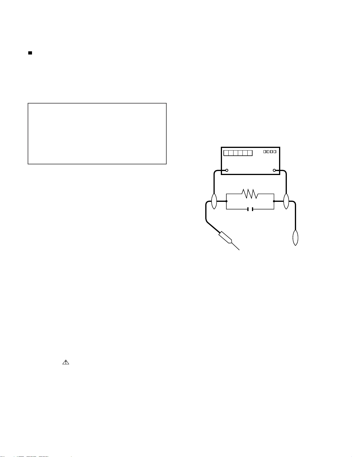
• Use an AC voltmeter having with 5000 ohm per volt, or higher, sensitivity or measure the AC voltage drop across the resistor.
• Connect the resistor connection to all exposed metal parts having a
return to the chassis (antenna, metal cabinet, screw heads, knobs
and control shafts, escutcheon, etc.) and measure the AC voltage
drop across the resistor.
All checks must be repeated with the AC cord plug connection
reversed. (If necessary, a nonpolarized adaptor plug must be used
only for the purpose of completing these checks.)
Any reading of 1.05 V peak (this corresponds to 0.7 mA peak AC.)
or more is excessive and indicates a potential shock hazard which
must be corrected before returning the monitor to the owner.
F7103 (3.15A/250V) (LC-32/37D653E/D654E)
F7000 (4A/250V), F7001 (4A/250V)
(LC-46D653E/D654E)
BEFORE RETURNING THE RECEIVER
(Fire & Shock Hazard)
Before returning the receiver to the user, perform the following
safety checks:
3. Inspect all lead dress to make certain that leads are not pinched,
and check that hardware is not lodged between the chassis and
other metal parts in the receiver.
4. Inspect all protective devices such as non-metallic control knobs,
insulation materials, cabinet backs, adjustment and compartment
covers or shields, isolation resistor-capacitor networks, mechanical
insulators, etc.
5. To be sure that no shock hazard exists, check for leakage current in
the following manner.
• Plug the AC cord directly into a 220~240 volt AC outlet.
• Using two clip leads, connect a 1.5k ohm, 10 watt resistor paralleled by a 0.15µF capacitor in series with all exposed metal cabinet
parts and a known earth ground, such as electrical conduit or electrical ground connected to an earth ground.
///////////////////////////////////////////////////////////////////////////////////////////////////////////////////////////////////////////////////////////////////////////////////////////////////////////////////////////////////////////
SAFETY NOTICE
Many electrical and mechanical parts in LCD color television have
special safety-related characteristics.
These characteristics are often not evident from visual inspection, nor
can protection afforded by them be necessarily increased by using
replacement components rated for higher voltage, wattage, etc.
Replacement parts which have these special safety characteristics are
identified in this manual; electrical components having such features
are identified by “ ” and shaded areas in the Replacement Parts
List and Schematic Diagrams.
///////////////////////////////////////////////////////////////////////////////////////////////////////////////////////////////////////////////////////////////////////////////////////////////////////////////////////////////////////////
TO EXPOSED
METAL PARTS
For continued protection, replacement parts must be identical to those
used in the original circuit.
The use of a substitute replacement parts which do not have the same
safety characteristics as the factory recommended replacement parts
shown in this service manual, may create shock, fire or other hazards.
DVM
AC SCALE
1.5k ohm
10W
0.15µF
TEST PROBE
CONNECT TO
KNOWN EARTH
GROUND
iii
Page 5
LC-32D653E/D654E, LC-37D653E/D654E, LC-46D653E/D654E
Precautions for using lead-free solder
Employing lead-free solder
• “PWBs” of this model employs lead-free solder. The LF symbol indicates lead-free solder, and is attached on the PWBs and service manuals. The
alphabetical character following LF shows the type of lead-free solder.
Example:
L Fa
Indicates lead-free solder of tin, silver and copper.
Indicates lead-free solder of tin, silver and copper.
L F a/a
Using lead-free wire solder
• When fixing the PWB soldered with the lead-free solder, apply lead-free wire solder. Repairing with conventional lead wire solder may cause damage or accident due to cracks.
As the melting point of lead-free solder (Sn-Ag-Cu) is higher than the lead wire solder by 40 °C, we recommend you to use a dedicated soldering
bit, if you are not familiar with how to obtain lead-free wire solder or soldering bit, contact our service station or service branch in your area.
Soldering
• As the melting point of lead-free solder (Sn-Ag-Cu) is about 220 °C which is higher than the conventional lead solder by 40 °C, and as it has poor
solder wettability, you may be apt to keep the soldering bit in contact with the PWB for extended period of time. However, Since the land may be
peeled off or the maximum heat-resistance temperature of parts may be exceeded, remove the bit from the PWB as soon as you confirm the
steady soldering condition.
Lead-free solder contains more tin, and the end of the soldering bit may be easily corroded. Make sure to turn on and off the power of the bit as
required.
If a different type of solder stays on the tip of the soldering bit, it is alloyed with lead-free solder. Clean the bit after every use of it.
When the tip of the soldering bit is blackened during use, file it with steel wool or fine sandpaper.
• Be careful when replacing parts with polarity indication on the PWB silk.
Lead-free wire solder for servicing
Part No. Description Code
ZHNDAi123250E J φ0.3mm 250g (1roll) BL
ZHNDAi126500E J φ0.6mm 500g (1roll) BK
ZHNDAi12801KE J φ1.0mm 1kg (1roll) BM
iv
Page 6

LC-32D653E/D654E, LC-37D653E/D654E, LC-46D653E/D654E
LC32D653E
CHAPTER 1. ADJUSTMENT PROCEDURE
Service Manual
[1] ADJUSTMENT PROCEDURE
1. Adjustment method after PWB and/or IC replacement due to repair
The unit is set to the optimum at the time of shipment from the factory. If any value should become improper or any adjustment is necessary due to
the part replacement, make an adjustment according to the following procedure.
1. Procure the following units in order to replace the main unit, IC8101.
MAIN UNIT: DUNTKE685FM31 (LC-32D653E)
DUNTKE685FM33 (LC-32D654E)
DUNTKE685FM32 (LC-37D653E)
DUNTKE685FM34 (LC-37D654E)
DUNTKE685FM36 (LC-46D653E)
DUNTKE685FM37 (LC-46D654E)
NOTE: [Caution when replacing ICs in the main unit (IC1504)]
The above ICs are EEPROMs storing the EDID data of HDMI. Before replacing the relevant part, procure the following parts in which the data
have been rewritten.
IC1504 RH-iXC442WJN1S EDID (HDMI)
IC1503 RH-iXC697WJQZS EDID (PC)
IC2003 RH-iXC331WJNNQ UCON (LC-46D653E/D654E)
1 – 1
Page 7

LC32D653E
CHAPTER 2. SCHEMATIC DIAGRAM
[1] DESCRIPTION OF SCHEMATIC DIAGRAM
VOLTAGE MEASUREMENT CONDITION:
1. The voltages at test points are measured on exclusive AC adaptor and the stable supply voltage of AC 230V.
Signals are fed by a colour bar signal generator for servicing purpose and the above voltages are measured with a 20k ohm/V tester.
INDICATION OF RESISTOR & CAPACITOR:
RESISTOR
1. The unit of resistance “Ω” is omitted.
(K=kΩ=1000 Ω, M=MΩ).
2. All resistors are ± 5%, unless otherwise noted.
(K= ± 10%, F= ± 1%, D= ± 0.5%)
3. All resistors are 1/16W, unless otherwise noted.
CAPACITOR
1. All capacitors are µF, unless otherwise noted.
(P=pF=µµF).
2. All capacitors are 50V, unless otherwise noted.
LC-32D653E/D654E, LC-37D653E/D654E, LC-46D653E/D654E
Service Manual
CAUTION:
This circuit diagram is original one, therefore there may be a
slight difference from yours.
SAFETY NOTES:
1. DISCONNECT THE AC PLUG FROM THE AC
OUTLET BEFORE REPLACING PARTS.
2. SEMICONDUCTOR HEAT SINKS SHOULD BE
REGARDED AS POTENTIAL SHOCK HAZARDS
WHEN THE CHASSIS IS OPERATING.
IMPORTANT SAFETY NOTICE:
PARTS MARKED WITH “ ” ( ) ARE
IMPORTANT FOR MAINTAINING THE SAFETY OF THE
SET. BE SURE TO REPLACE THESE PARTS WITH
SPECIFIED ONES FOR MAINTAINING THE SAFETY AND
PERFORMANCE OF THE SET.
2 – 1
Page 8
LC-32D653E/D654E, LC-37D653E/D654E, LC-46D653E/D654E
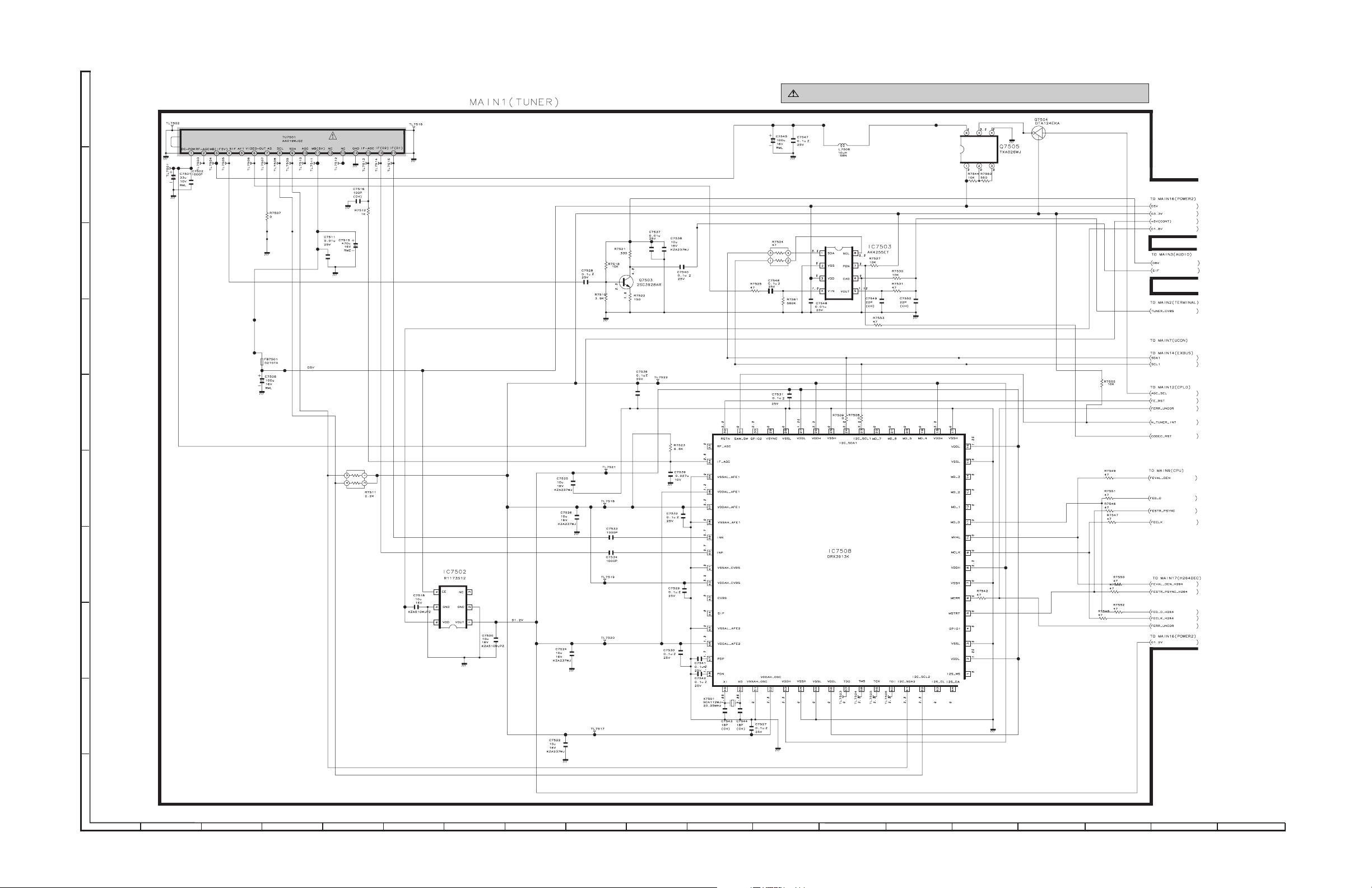
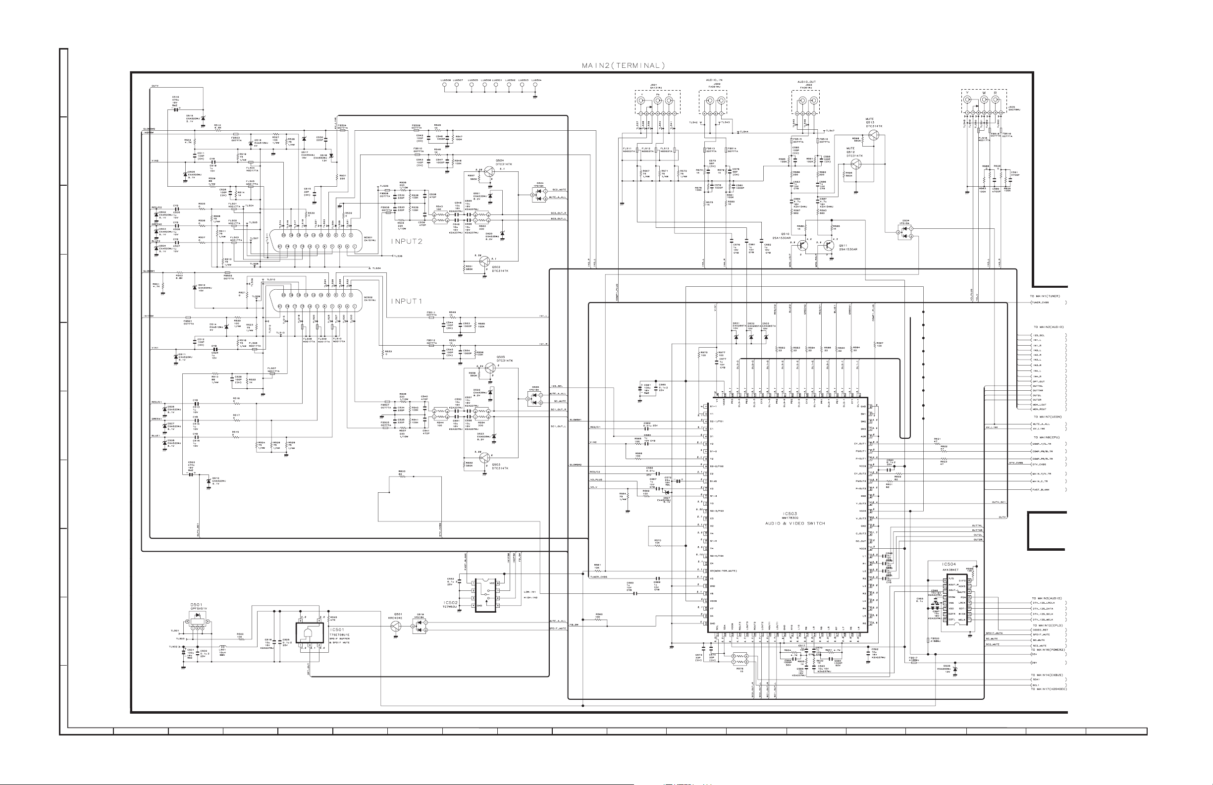
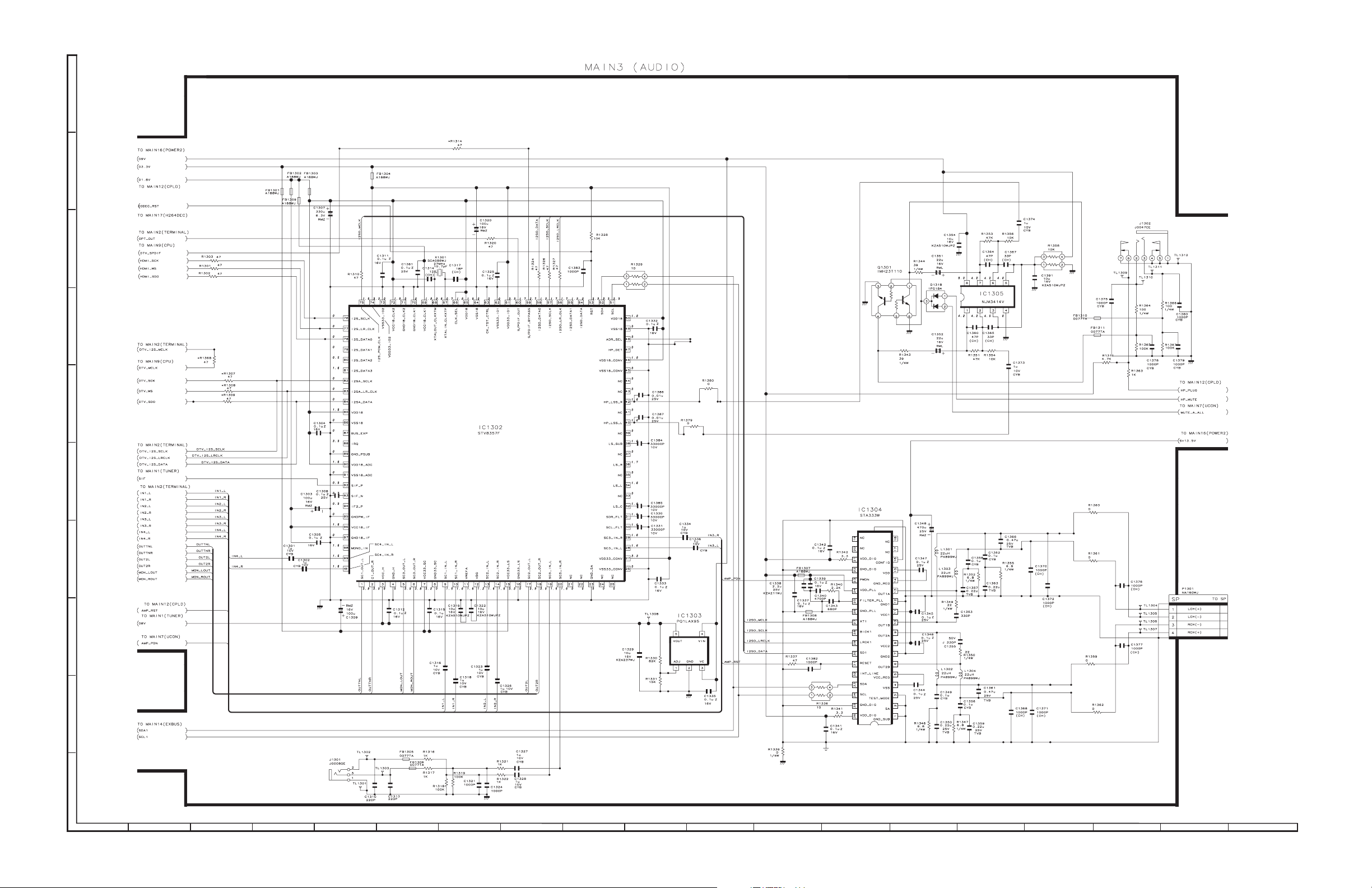
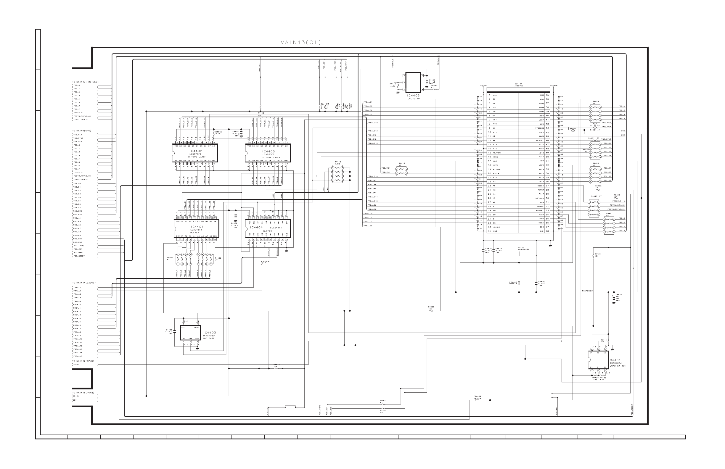
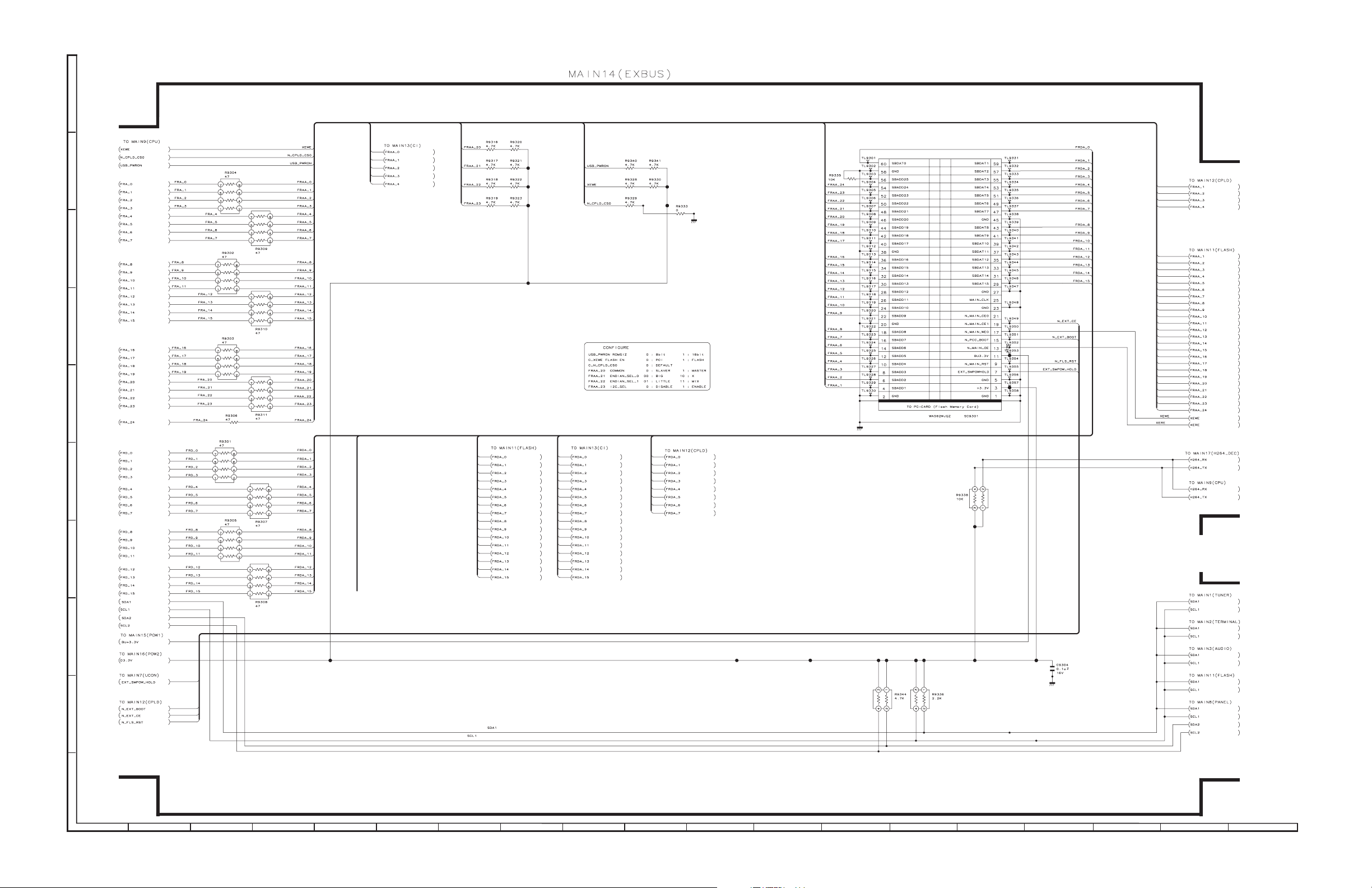
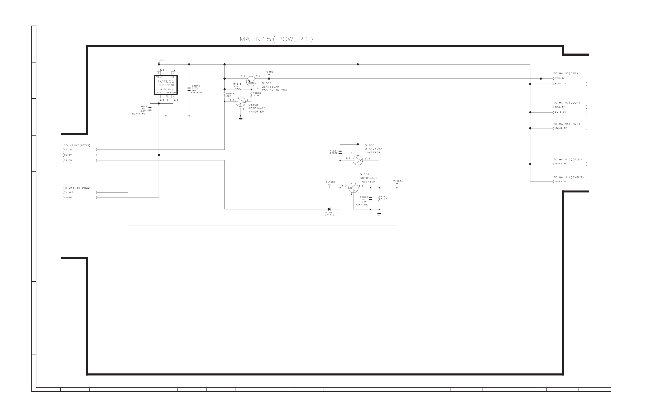
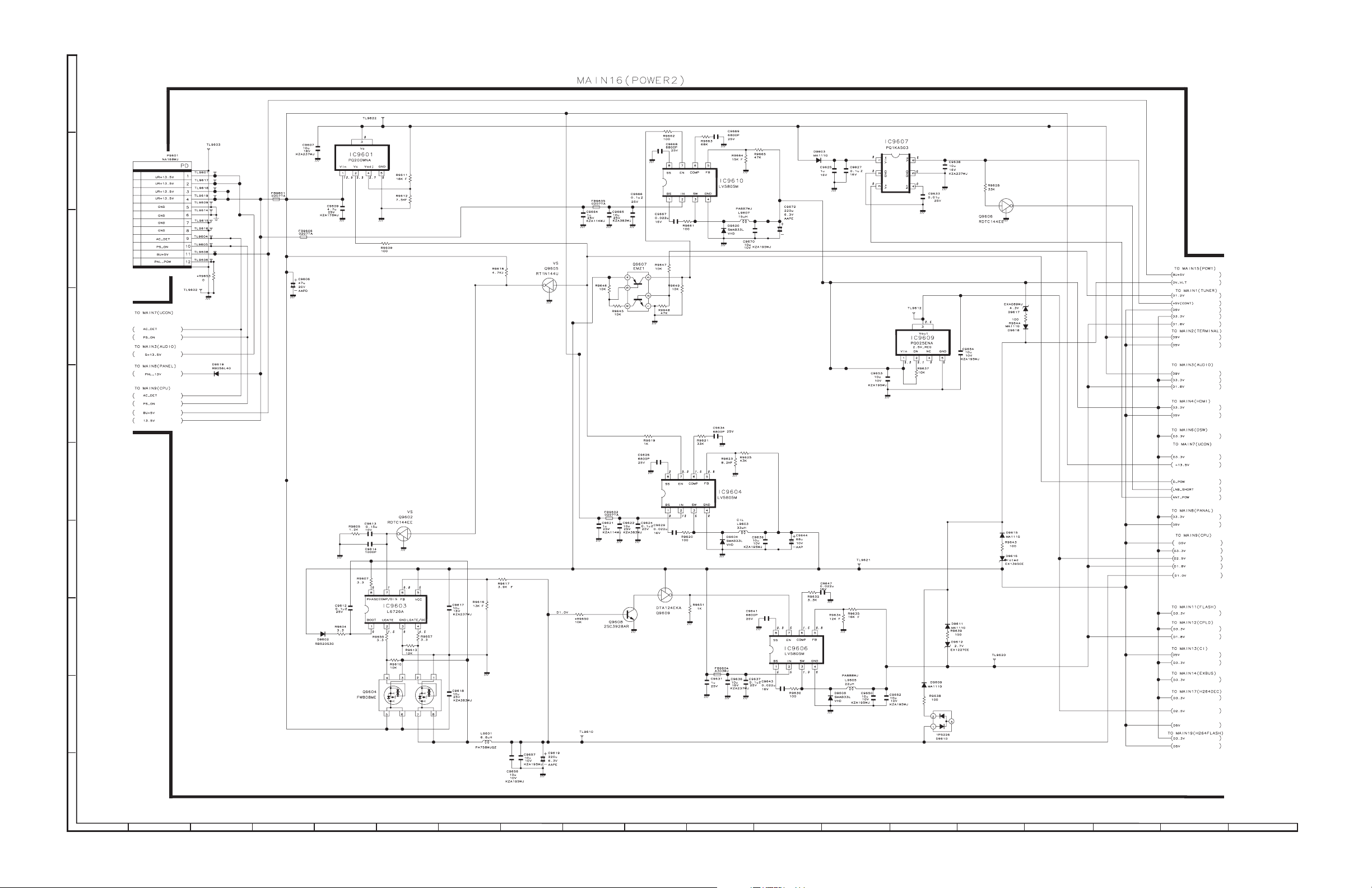
[2] SCHEMATIC DIAGRAM (LC-32/37D653E/D654E)
MAIN Unit-1
J
I
H
G
AND SHADED COMPONENTS=SAFETY RELATED PARTS
F
E
D
C
B
A
1
23
8
1097654
1311 191816151412 17
2 – 2
Page 9
MAIN Unit-2
J
I
H
G
LC-32D653E/D654E, LC-37D653E/D654E, LC-46D653E/D654E
F
E
D
C
B
A
1
23
8
1097654
1311 191816151412 17
2 – 3
Page 10
LC-32D653E/D654E, LC-37D653E/D654E, LC-46D653E/D654E
MAIN Unit-3
J
I
H
G
F
E
D
C
B
A
1
23
8
1097654
1311 191816151412 17
2 – 4
Page 11
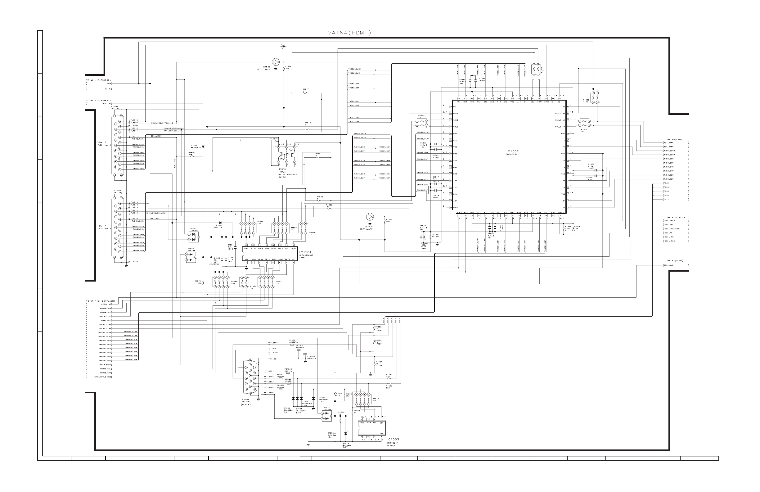
MAIN Unit-4
J
I
H
G
LC-32D653E/D654E, LC-37D653E/D654E, LC-46D653E/D654E
F
E
D
C
B
A
1
23
8
1097654
1311 191816151412 17
2 – 5
Page 12
LC-32D653E/D654E, LC-37D653E/D654E, LC-46D653E/D654E
MAIN Unit-5
J
I
H
G
F
E
D
C
B
A
1
23
8
1097654
1311 191816151412 17
2 – 6
Page 13
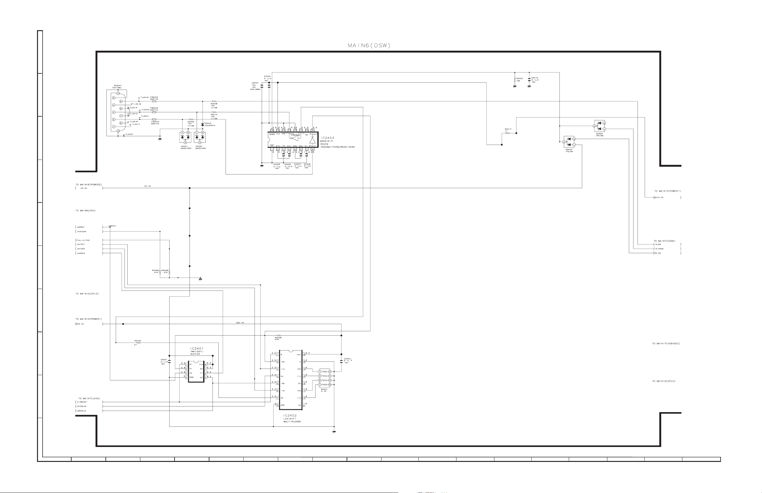
MAIN Unit-6
J
I
H
G
LC-32D653E/D654E, LC-37D653E/D654E, LC-46D653E/D654E
F
E
D
C
B
A
1
23
8
1097654
1311 191816151412 17
2 – 7
Page 14
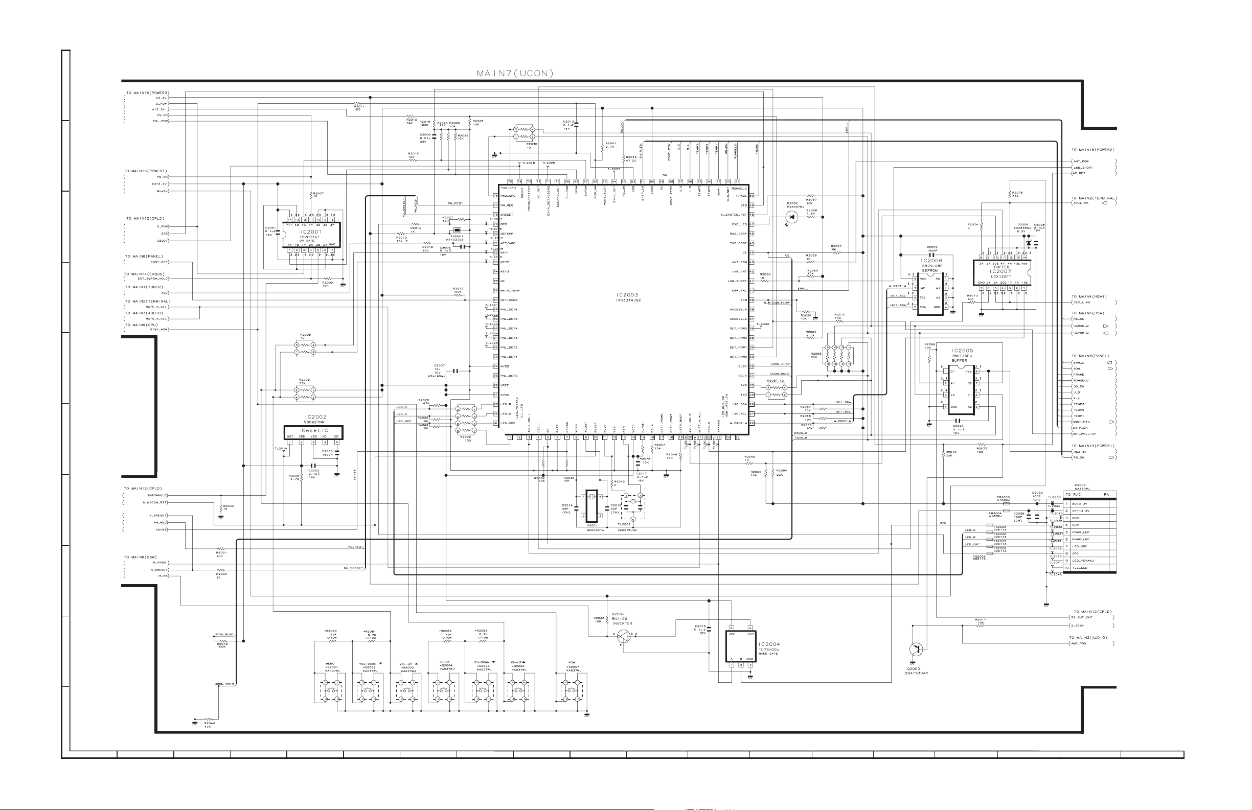
LC-32D653E/D654E, LC-37D653E/D654E, LC-46D653E/D654E
MAIN Unit-7
J
I
H
G
F
E
D
C
B
A
1
23
8
1097654
1311 191816151412 17
2 – 8
Page 15
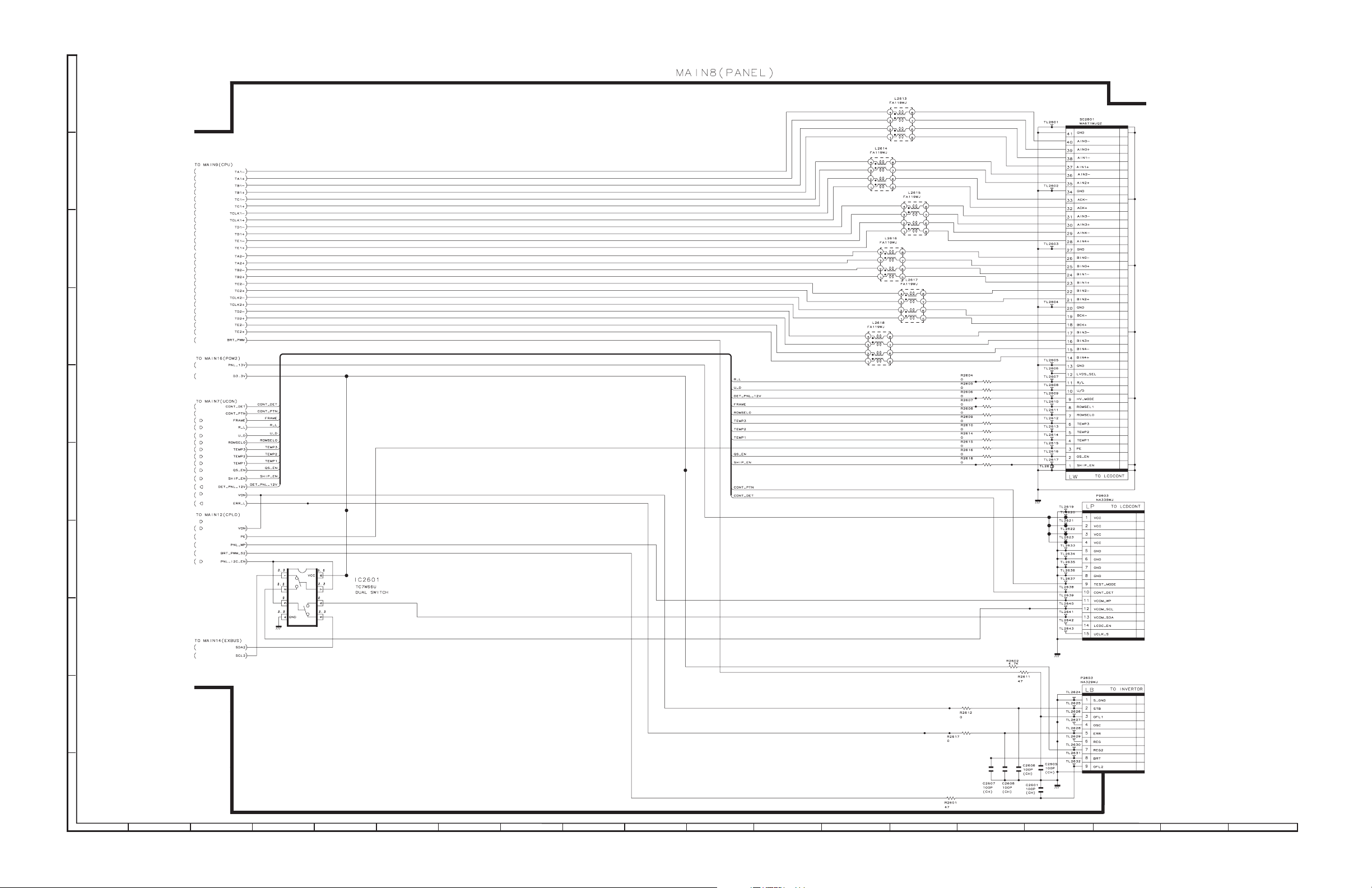
MAIN Unit-8
J
I
H
G
LC-32D653E/D654E, LC-37D653E/D654E, LC-46D653E/D654E
F
E
D
C
B
A
1
23
8
1097654
1311 191816151412 17
2 – 9
Page 16
LC-32D653E/D654E, LC-37D653E/D654E, LC-46D653E/D654E
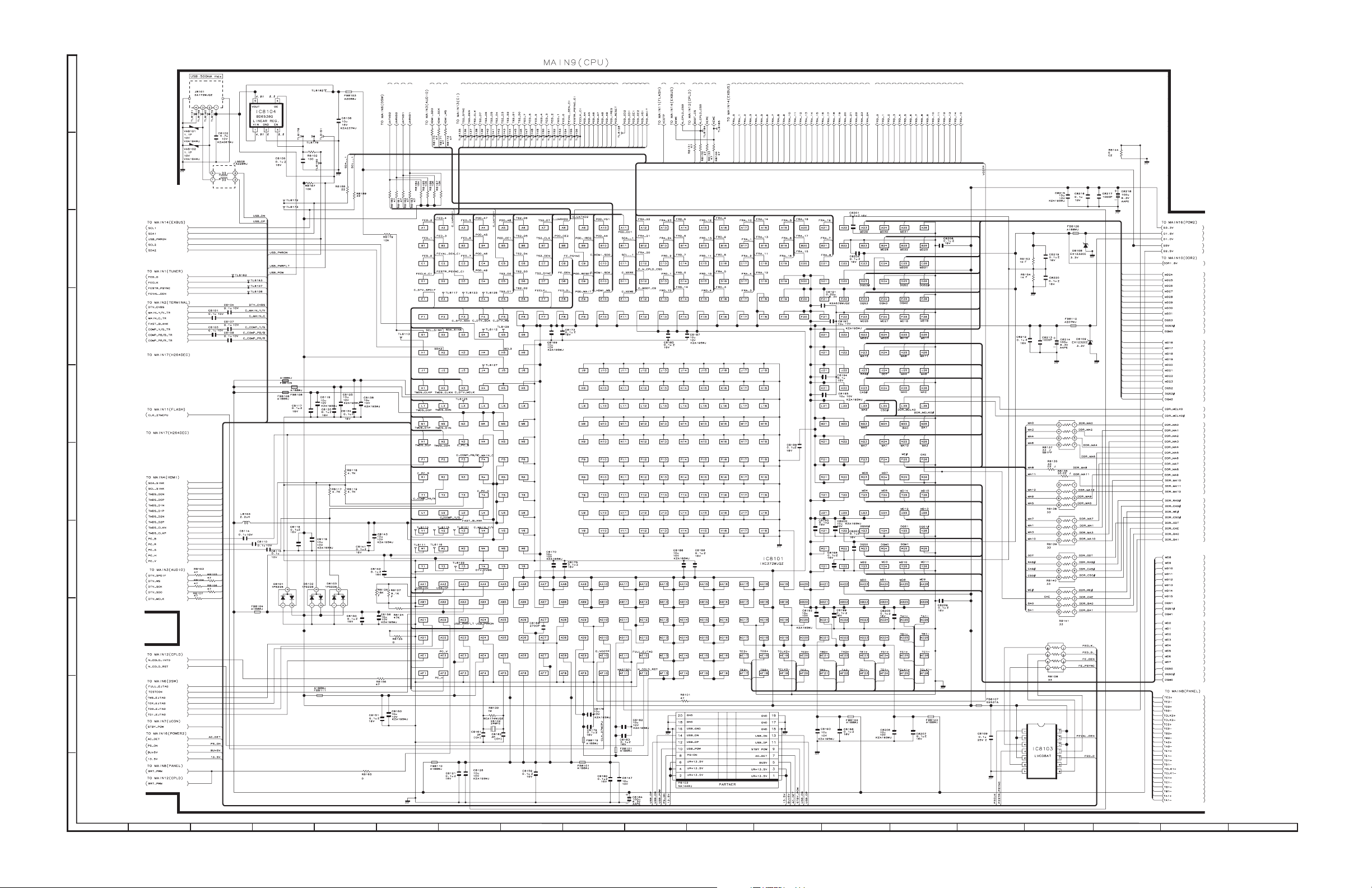
MAIN Unit-9
J
I
H
G
F
E
D
C
B
A
1
23
8
1097654
1311 191816151412 17
2 – 10
Page 17
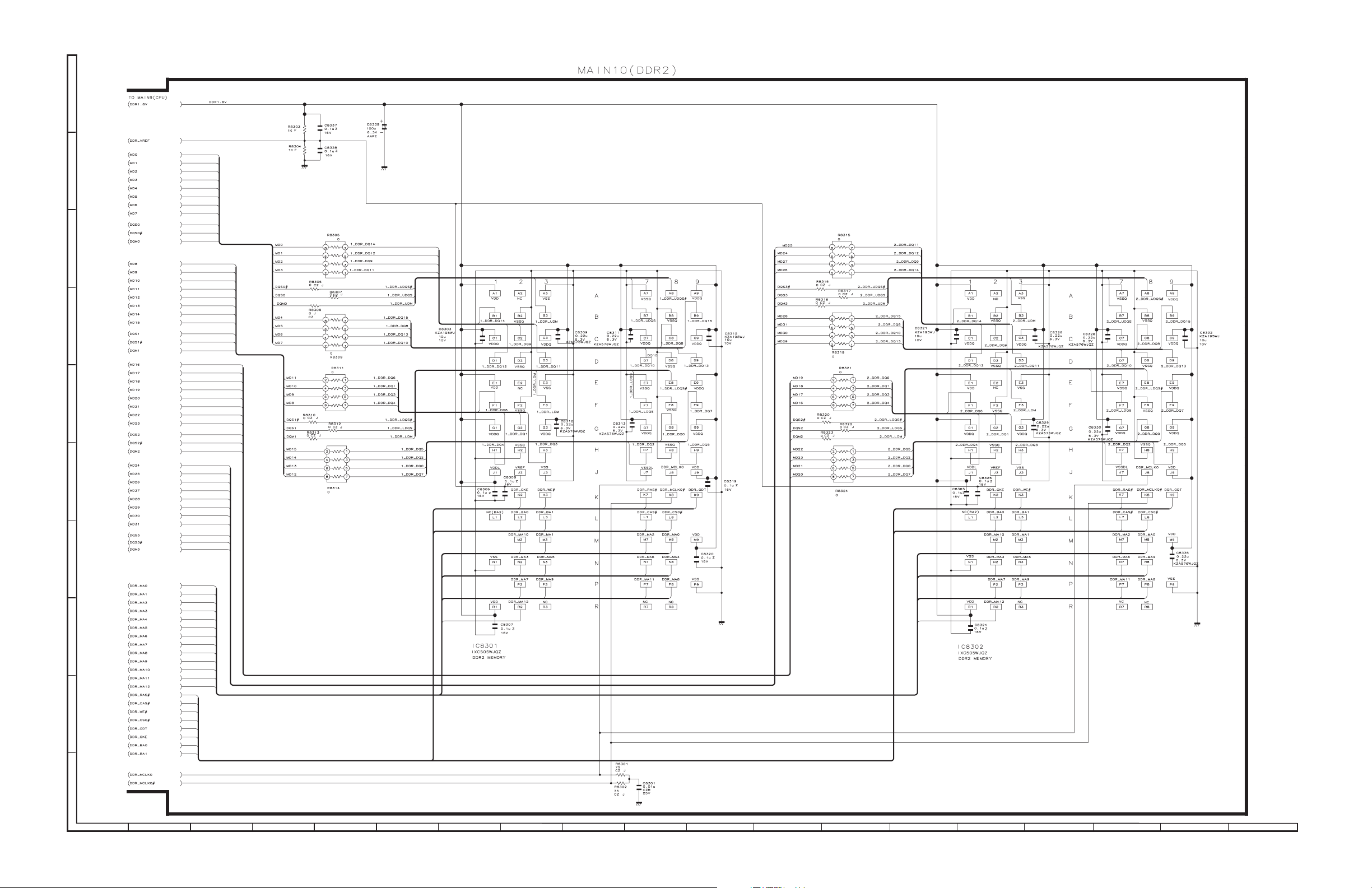
MAIN Unit-10
J
I
H
G
LC-32D653E/D654E, LC-37D653E/D654E, LC-46D653E/D654E
F
E
D
C
B
A
1
23
8
1097654
1311 191816151412 17
2 – 11
Page 18
LC-32D653E/D654E, LC-37D653E/D654E, LC-46D653E/D654E
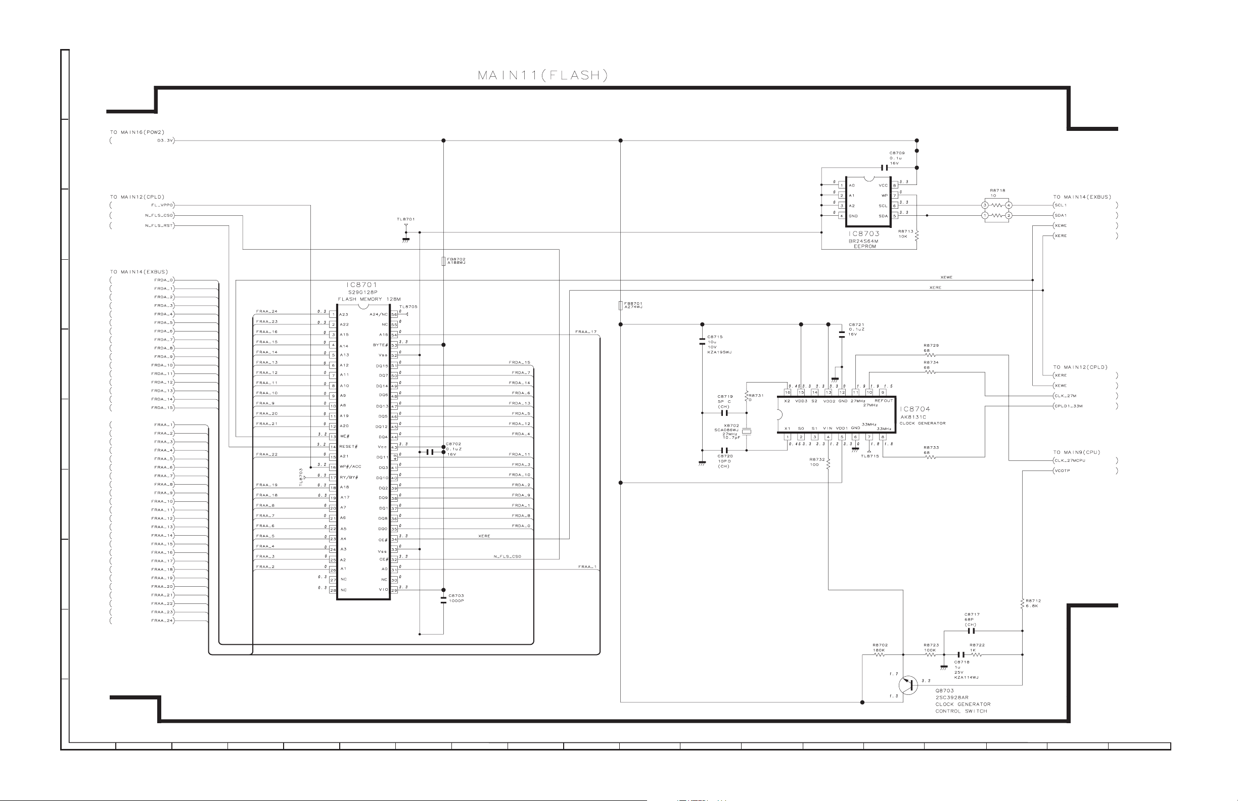
MAIN Unit-11
J
I
H
G
F
E
D
C
B
A
1
23
8
1097654
1311 191816151412 17
2 – 12
Page 19
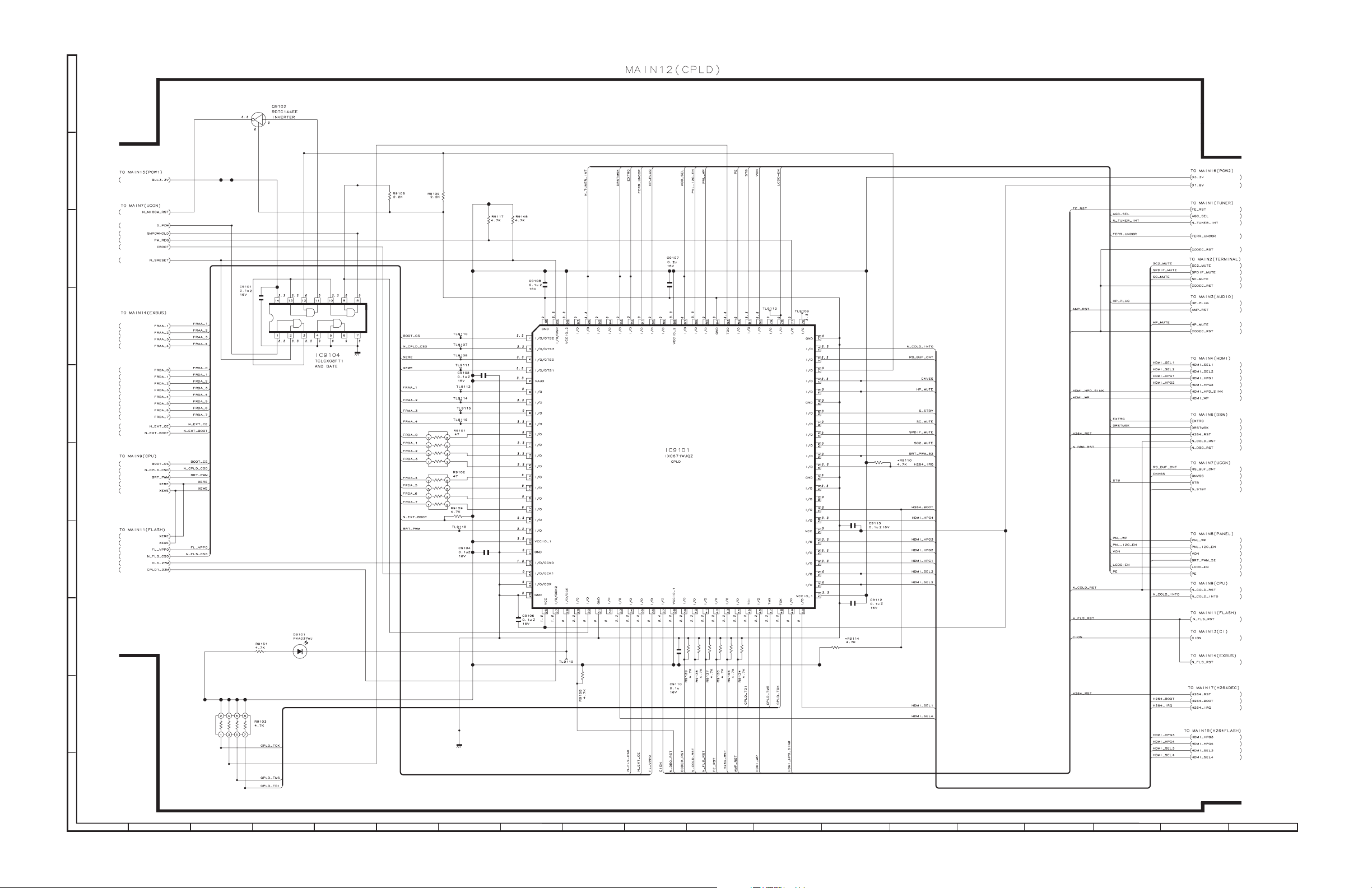
MAIN Unit-12
J
I
H
G
LC-32D653E/D654E, LC-37D653E/D654E, LC-46D653E/D654E
F
E
D
C
B
A
1
23
8
1097654
1311 191816151412 17
2 – 13
Page 20
LC-32D653E/D654E, LC-37D653E/D654E, LC-46D653E/D654E
MAIN Unit-13
J
I
H
G
F
E
D
C
B
A
1
23
8
1097654
1311 191816151412 17
2 – 14
Page 21
MAIN Unit-14
J
I
H
G
LC-32D653E/D654E, LC-37D653E/D654E, LC-46D653E/D654E
F
E
D
C
B
A
1
23
8
1097654
1311 191816151412 17
2 – 15
Page 22
LC-32D653E/D654E, LC-37D653E/D654E, LC-46D653E/D654E
MAIN Unit-15
J
I
H
G
F
E
D
C
B
A
1
23
8
1097654
1311 191816151412 17
2 – 16
Page 23
MAIN Unit-16
J
I
H
G
LC-32D653E/D654E, LC-37D653E/D654E, LC-46D653E/D654E
F
E
D
C
B
A
1
23
8
1097654
1311 191816151412 17
2 – 17
Page 24

LC-32D653E/D654E, LC-37D653E/D654E, LC-46D653E/D654E
[3] SCHEMATIC DIAGRAM (LC-46D653E/D654E)
MAIN Unit-1
J
I
H
G
AND SHADED COMPONENTS=SAFETY RELATED PARTS
F
E
D
C
B
A
1
23
8
1097654
1311 191816151412 17
2 – 18
Page 25

MAIN Unit-2
J
I
H
G
LC-32D653E/D654E, LC-37D653E/D654E, LC-46D653E/D654E
F
E
D
C
B
A
1
23
8
1097654
1311 191816151412 17
2 – 19
Page 26

LC-32D653E/D654E, LC-37D653E/D654E, LC-46D653E/D654E
MAIN Unit-3
J
I
H
G
F
E
D
C
B
A
1
23
8
1097654
1311 191816151412 17
2 – 20
Page 27

MAIN Unit-4
J
I
H
G
LC-32D653E/D654E, LC-37D653E/D654E, LC-46D653E/D654E
F
E
D
C
B
A
1
23
8
1097654
1311 191816151412 17
2 – 21
Page 28

LC-32D653E/D654E, LC-37D653E/D654E, LC-46D653E/D654E
MAIN Unit-5
J
I
H
G
F
E
D
C
B
A
1
23
8
1097654
1311 191816151412 17
2 – 22
Page 29

MAIN Unit-6
J
I
H
G
LC-32D653E/D654E, LC-37D653E/D654E, LC-46D653E/D654E
F
E
D
C
B
A
1
23
8
1097654
1311 191816151412 17
2 – 23
Page 30

LC-32D653E/D654E, LC-37D653E/D654E, LC-46D653E/D654E
MAIN Unit-7
J
I
H
G
F
E
D
C
B
A
1
23
8
1097654
1311 191816151412 17
2 – 24
Page 31

MAIN Unit-8
J
I
H
G
LC-32D653E/D654E, LC-37D653E/D654E, LC-46D653E/D654E
F
E
D
C
B
A
1
23
8
1097654
1311 191816151412 17
2 – 25
Page 32

LC-32D653E/D654E, LC-37D653E/D654E, LC-46D653E/D654E
MAIN Unit-9
J
I
H
G
F
E
D
C
B
A
1
23
8
1097654
1311 191816151412 17
2 – 26
Page 33

MAIN Unit-10
J
I
H
G
LC-32D653E/D654E, LC-37D653E/D654E, LC-46D653E/D654E
F
E
D
C
B
A
1
23
8
1097654
1311 191816151412 17
2 – 27
Page 34

LC-32D653E/D654E, LC-37D653E/D654E, LC-46D653E/D654E
MAIN Unit-11
J
I
H
G
F
E
D
C
B
A
1
23
8
1097654
1311 191816151412 17
2 – 28
Page 35

MAIN Unit-12
J
I
H
G
LC-32D653E/D654E, LC-37D653E/D654E, LC-46D653E/D654E
F
E
D
C
B
A
1
23
8
1097654
1311 191816151412 17
2 – 29
Page 36

LC-32D653E/D654E, LC-37D653E/D654E, LC-46D653E/D654E
MAIN Unit-13
J
I
H
G
F
E
D
C
B
A
1
23
8
1097654
1311 191816151412 17
2 – 30
Page 37

MAIN Unit-14
J
I
H
G
LC-32D653E/D654E, LC-37D653E/D654E, LC-46D653E/D654E
F
E
D
C
B
A
1
23
8
1097654
1311 191816151412 17
2 – 31
Page 38

LC-32D653E/D654E, LC-37D653E/D654E, LC-46D653E/D654E
MAIN Unit-15
J
I
H
G
F
E
D
C
B
A
1
23
8
1097654
1311 191816151412 17
2 – 32
Page 39

MAIN Unit-16
J
I
H
G
LC-32D653E/D654E, LC-37D653E/D654E, LC-46D653E/D654E
F
E
D
C
B
A
1
23
8
1097654
1311 191816151412 17
2 – 33
Page 40

LC-32D653E/D654E, LC-37D653E/D654E, LC-46D653E/D654E
— M E M O —
2 – 34
Page 41

PartsGuide
LC-32D653E/D654E, LC-37D653E/D654E, LC-46D653E/D654E
PARTS GUIDE
No. SX8S6LC32D653
LCD COLOUR TELEVISION
LC-32D653E
LC-32D654E
LC-37D653E
LC-37D654E
LC-46D653E
CONTENTS
[1] PRINTED WIRING BOARD
ASSEMBLIES (LC-32D653E)
[2] PRINTED WIRING BOARD
ASSEMBLIES (LC-32D654E)
[3] PRINTED WIRING BOARD
ASSEMBLIES (LC-37D653E)
[4] PRINTED WIRING BOARD
ASSEMBLIES (LC-37D654E)
[5] PRINTED WIRING BOARD
ASSEMBLIES (LC-46D653E)
[6] PRINTED WIRING BOARD
ASSEMBLIES (LC-46D654E)
[7] LCD PANEL
[8] DUNTKE685FM31/FM33/FM32/
FM34/FM36/FM37 (MAIN Unit)
MODELS
[11] CABINET PARTS
[12] LCD PANEL MODULE ASSEMBLY
[13] CABINET PARTS
[14] LCD MODULE Assembly
[15] SUPPLIED ACCESSORIES
[16] PACKING PARTS
[17] PACKING PARTS
[18] PACKING PARTS
LC-46D654E
(LC-37D653E/D654E)
(LC-37D653E/D654E)
(LC-46D653E/D654E)
(LC-46D653E/D654E)
(LC-32D653E/D654E)
(LC-37D653E/D654E)
(LC-46D653E/D654E)
[9] CABINET PARTS
(LC-32D653E/D654E)
[10] LCD PANEL MODULE ASSEMBLY
(LC-32D653E/D654E)
Parts marked with " " are important for maintaining the safety of the set. Be sure to replace these
parts with specified ones for maintaining the safety and performance of the set.
[19] SERVICE JIGS
This document has been published to be used
for after sales service only.
The contents are subject to change without notice.
Page 42

LC-32D653E/D654E, LC-37D653E/D654E, LC-46D653E/D654E
NO. PARTS CODE
PRICE
RANK
[1] PRINTED WIRING BOARD ASSEMBLIES (LC-32D653E)
N DUNTKE685FM31 CM N R MAIN Unit
N DUNTKE687FM31 AZ N R R/C LED Unit
N RUNTKA456WJQZ BS N S POWER/INVERTER Unit (Not Replacement Item)
[2] PRINTED WIRING BOARD ASSEMBLIES (LC-32D654E)
N DUNTKE685FM33 CM N R MAIN Unit
N DUNTKE687FM33 AZ N R R/C LED Unit
N RUNTKA456WJQZ BS N S POWER/INVERTER Unit (Not Replacement Item)
[3] PRINTED WIRING BOARD ASSEMBLIES (LC-37D653E)
N DUNTKE685FM32 CM N R MAIN Unit
N DUNTKE687FM32 AZ N R R/C LED Unit
N RDENCA267WJQZ BL N S POWER Unit (Not Replacement Item)
N RUNTKA457WJQZ BK N S INVERTER Unit (Not Replacement Item)
[4] PRINTED WIRING BOARD ASSEMBLIES (LC-37D654E)
N DUNTKE685FM34 CM N R MAIN Unit
N DUNTKE687FM34 AZ N R R/C LED Unit
N RDENCA267WJQZ BL N S POWER Unit (Not Replacement Item)
N RUNTKA457WJQZ BK N S INVERTER Unit (Not Replacement Item)
[5] PRINTED WIRING BOARD ASSEMBLIES (LC-46D653E)
N DUNTKE266FM01 AR N R KEY Unit
N DUNTKE685FM36 CL N R MAIN Unit
N DUNTKE687FM36 AZ N R LED Unit
N RDENCA308WJQZ BP N S POWER Unit (Unit Replacement Item)
[6] PRINTED WIRING BOARD ASSEMBLIES (LC-46D654E)
N DUNTKE266FM01 AR N R KEY Unit
N DUNTKE685FM37 CV N R MAIN Unit
N DUNTKE687FM37 BD N R LED Unit
N RDENCA308WJQZ BP N S POWER Unit (Unit Replacement Item)
[7] LCD PANEL
N R1LK315D3LW1AS DG N J 32" LCD Panel Module (LC-32D653E/D654E)
N R1LK370D3LW10Y DE N J 37" LCD Panel Module (LC-37D653E/D654E)
N R1LK460D3LW6AY EC N J 46" LCD Panel Module (LC-46D653E/D654E)
[8] DUNTKE685FM31/FM33/FM32/FM34/FM36/FM37 (MAIN Unit)
C502 VCKYCZ1EF104ZY AA J Capacitor 0.1 25V Ceramic
C503 VCEASY1CN477MY AD J Capacitor 470 16V Electrolytic
C504 VCKYCZ1HB102KY AB J Capacitor 1000p 50V Ceramic
C505 VCKYCY1AB105KY AB J Capacitor 1 10V Ceramic
C506 VCKYCY1AB105KY AB J Capacitor 1 10V Ceramic
C507 VCKYCY1AB105KY AB J Capacitor 1 10V Ceramic
C511 VCCCCZ1HH101JY AB J Capacitor 100p 50V Ceramic
C512 VCCCCZ1HH101JY AB J Capacitor 100p 50V Ceramic
C513 VCKYCY1AB105KY AB J Capacitor 1 10V Ceramic
C514 VCKYCY1AB105KY AB J Capacitor 1 10V Ceramic
C515 VCKYCY1AB105KY AB J Capacitor 1 10V Ceramic
C516 VCEASY1CN477MY AD J Capacitor 470 16V Electrolytic
C517 VCKYCY1AB105KY AB J Capacitor 1 10V Ceramic
C518 RC-KZA237WJZZY AB J Capacitor 10 16V Ceramic
C519 VCKYCY1AB105KY AB J Capacitor 1 10V Ceramic
C524 VCKYCY1AB105KY AB J Capacitor 1 10V Ceramic
C525 VCKYCZ1EF104ZY AA J Capacitor 0.1 25V Ceramic
C528 VCCCCZ1HH101JY AB J Capacitor 100p 50V Ceramic
C529 VCCCCZ1HH101JY AB J Capacitor 100p 50V Ceramic
C530 VCKYCZ1HB221KY AA J Capacitor 220p 50V Ceramic
C532 VCKYCZ1HB331KY AA J Capacitor 330p 50V Ceramic
C533 VCKYCZ1HB331KY AA J Capacitor 330p 50V Ceramic
C534 VCKYCZ1HB331KY AA J Capacitor 330p 50V Ceramic
C535 VCKYCZ1HB331KY AA J Capacitor 330p 50V Ceramic
C538 VCKYCZ1HB471KY AB J Capacitor 470p 50V Ceramic
C539 VCKYCZ1HB471KY AB J Capacitor 470p 50V Ceramic
C540 VCKYCZ1HB471KY AB J Capacitor 470p 50V Ceramic
C541 VCKYCZ1HB471KY AB J Capacitor 470p 50V Ceramic
C542 VCCCCZ1HH101JY AB J Capacitor 100p 50V Ceramic
C543 VCCCCZ1HH101JY AB J Capacitor 100p 50V Ceramic
C544 VCCCCZ1HH101JY AB J Capacitor 100p 50V Ceramic
C545 VCCCCZ1HH101JY AB J Capacitor 100p 50V Ceramic
C546 VCKYCZ1HB102KY AB J Capacitor 1000p 50V Ceramic
C547 VCKYCZ1HB102KY AB J
C548 RC-KZA237WJZZY AB J Capacitor 10 16V Ceramic
C549 RC-KZA237WJZZY AB J Capacitor 10 16V Ceramic
C550 RC-KZA237WJZZY AB J Capacitor 10 16V Ceramic
C551 RC-KZA237WJZZY AB J Capacitor 10 16V Ceramic
C552 VCKYCZ1EF104ZY AA J Capacitor 0.1 25V Ceramic
C553 VCKYCZ1HB102KY AB J Capacitor 1000p 50V Ceramic
C554 VCKYCZ1HB102KY AB J Capacitor 1000p 50V Ceramic
C555 RC-KZA237WJZZY AB J Capacitor 10 16V Ceramic
C556 RC-KZA237WJZZY AB J Capacitor 10 16V Ceramic
C557 RC-KZA237WJZZY AB J Capacitor 10 16V Ceramic
C558 RC-KZA237WJZZY AB J Capacitor 10 16V Ceramic
NEW
MARK
PAR T
DELIVERY
Capacitor 1000p 50V Ceramic
DESCRIPTION
2
Page 43

LC-32D653E/D654E, LC-37D653E/D654E, LC-46D653E/D654E
NO. PARTS CODE
PRICE
RANK
[8] DUNTKE685FM31/FM33/FM32/FM34/FM36/FM37 (MAIN Unit)
C560 VCKYCY1AB105KY AB J Capacitor 1 10V Ceramic
C561 VCERMZ1CN107MY AD J Capacitor 100 16V Electrolytic
C562 VCKYCZ1EB103KY AA J Capacitor 0.01 25V Ceramic
C563 VCKYCY1AB105KY AB J Capacitor 1 10V Ceramic
C565 VCKYCZ1EF104ZY AA J Capacitor 0.1 25V Ceramic
C566 VCKYCZ1EB103KY AA J Capacitor 0.01 25V Ceramic
C567 VCKYCY1AB105KY AB J Capacitor 1 10V Ceramic
C568 RC-KZA237WJZZY AB J Capacitor 10 16V Ceramic
C569 VCKYCY1AB105KY AB J Capacitor 1 10V Ceramic
C570 VCKYCY1AB105KY AB J Capacitor 1 10V Ceramic
C572 VCERML1CN226MY AC J Capacitor 22 16V Electrolytic (LC-32/37D653E/D654E)
C572 VCEASX1CN226MY AC J Capacitor 22 16V Electrolytic (LC-42D653E/D654E)
C573 VCCCCZ1HH330JY AB J Capacitor 33p 50V Ceramic
C574 VCCCCZ1HH330JY AB J Capacitor 33p 50V Ceramic
C575 VCCCCZ1HH560JY AB J Capacitor 56p 50V Ceramic
C576 VCKYCZ1HB102KY AB J Capacitor 1000p 50V Ceramic
C577 VCKYCY1AB105KY AB J Capacitor 1 10V Ceramic
C578 VCCCCZ1HH560JY AB J Capacitor 56p 50V Ceramic
C579 VCKYCY1AB105KY AB J Capacitor 1 10V Ceramic
C580 VCKYCZ1HB102KY AB J Capacitor 1000p 50V Ceramic
C581 VCKYCY1AB105KY AB J Capacitor 1 10V Ceramic
C582 VCKYCY1AB105KY AB J Capacitor 1 10V Ceramic
C583 VCKYCY1AB105KY AB J Capacitor 1 10V Ceramic
C584 RC-KZA154WJZZY AB J Capacitor 4.7 16V Ceramic
C585 VCCCCZ1HH101JY AB J Capacitor 100p 50V Ceramic
C586 VCKYCY1AB105KY AB J Capacitor 1 10V Ceramic
C587 RC-KZA154WJZZY AB J Capacitor 4.7 16V Ceramic
C588 VCCCCZ1HH101JY AB J Capacitor 100p 50V Ceramic
C589 VCKYCY1HB472KY AA J Capacitor 4700p 50V Ceramic
C590 VCKYCZ1EF104ZY AA J Capacitor 0.1 25V Ceramic
C591 VCKYCY1HB472KY AA J Capacitor 4700p 50V Ceramic
C592 RC-KZA237WJZZY AB J Capacitor 10 16V Ceramic
C593 RC-KZA237WJZZY AB J Capacitor 10 16V Ceramic
C594 VCKYCZ1HB102KY AB J
C595 VCKYCZ1EF104ZY AA J Capacitor 0.1 25V Ceramic
C596 RC-KZA237WJZZY AB J Capacitor 10 16V Ceramic
C597 RC-KZA237WJZZY AB J Capacitor 10 16V Ceramic
C598 VCKYCY1AB105KY AB J Capacitor 1 10V Ceramic
C599 VCKYCY1AB105KY AB J Capacitor 1 10V Ceramic
C600 VCKYCY1AB105KY AB J Capacitor 1 10V Ceramic
C601 VCKYCY1AB105KY AB J Capacitor 1 10V Ceramic
C615 VCCCCZ1HH330JY AB J Capacitor 33p 50V Ceramic
C1301 VCKYCY1AB105KY AB J Capacitor 1 10V Ceramic
C1302 VCKYCY1AB105KY AB J Capacitor 1 10V Ceramic
C1303 VCEASY1CN107MY AC J Capacitor 100 16V Electrolytic
C1304 VCKYCZ1CF104ZY AA J Capacitor 0.1 16V Ceramic
C1305 VCKYCZ1CF104ZY AA J Capacitor 0.1 16V Ceramic
C1307 VCEASY0JN337MY AC J Capacitor 370 6.3V Electrolytic
C1308 VCKYCZ1EF104ZY AA J Capacitor 0.1 25V Ceramic
C1309 VCEASY1CN107MY AC J Capacitor 100 16V Electrolytic
C1310 VCKYCZ1HB221KY AA J Capacitor 220p 50V Ceramic
C1311 VCKYCZ1CF104ZY AA J Capacitor 0.1 16V Ceramic
C1312 VCKYCZ1CF104ZY AA J Capacitor 0.1 16V Ceramic
C1313 VCKYCZ1HB221KY AA J Capacitor 220p 50V Ceramic
C1314 VCCCCZ1HH120JY AB J Capacitor 12p 50V Ceramic
C1315 VCKYCZ1CF104ZY AA J Capacitor 0.1 16V Ceramic
C1316 VCKYCY1AB105KY AB J Capacitor 1 10V Ceramic
C1317 VCCCCZ1HH180JY AB J Capacitor 18p 50V Ceramic
C1318 VCKYCY1AB105KY AB J Capacitor 1 10V Ceramic
C1319 RC-KZA510WJPZY AB J Capacitor 10 16V Ceramic
C1320 VCEASY1CN107MY AC J Capacitor 100 16V Electrolytic
C1321 VCKYCZ1HB102KY AB J Capacitor 1000p 50V Ceramic
C1322 RC-KZA510WJPZY AB J Capacitor 10 16V Ceramic
C1323 VCKYCY1AB105KY AB J Capacitor 1 10V Ceramic
C1324 VCKYCZ1HB102KY AB J Capacitor 1000p 50V Ceramic
C1325 VCKYCZ1CF104ZY AA J Capacitor 0.1 16V Ceramic
C1326 VCKYCY1AB105KY AB J Capacitor 1 10V Ceramic
C1327
C1328 VCKYCY1AB105KY AB J Capacitor 1 10V Ceramic
C1329 RC-KZA237WJZZY AB J Capacitor 10 16V Ceramic
C1330 VCKYCZ1AB333KY AB J Capacitor 0.033 10V Ceramic
C1331 VCKYCZ1AB333KY AB J Capacitor 0.033 10V Ceramic
C1332 VCKYCZ1CF104ZY AA J Capacitor 0.1 16V Ceramic
C1333 VCKYCZ1CF104ZY AA J Capacitor 0.1 16V Ceramic
C1334 VCKYCY1AB105KY AB J Capacitor 1 10V Ceramic
C1335 VCKYCZ1CF104ZY AA J Capacitor 0.1 16V Ceramic
C1336 VCKYCY1AB105KY AB J Capacitor 1 10V Ceramic
C1337 VCKYCZ1CF104ZY AA J Capacitor 0.1 16V Ceramic
C1338 RC-KZA211WJZZY AB J Capacitor 2.2 25V Ceramic
C1339 VCKYCZ1CF104ZY AA J Capacitor 0.1 16V Ceramic
C1340 VCKYCZ1HB472KY AA J Capacitor 4700p 50V Ceramic
C1341 VCKYCZ1CF104ZY AA J Capacitor 0.1 16V Ceramic
C1342 VCKYCZ1CF104ZY AA J Capacitor 0.1 16V Ceramic
C1343 VCKYCZ1HB681KY AB J Capacitor 680p 50V Ceramic
C1344 VCKYCZ1EF104ZY AA J Capacitor 0.1 25V Ceramic
VCKYCY1AB105KY AB J Capacitor 1 10V Ceramic
NEW
MARK
PAR T
DELIVERY
DESCRIPTION
Capacitor 1000p 50V Ceramic
3
Page 44

LC-32D653E/D654E, LC-37D653E/D654E, LC-46D653E/D654E
NO. PARTS CODE
PRICE
RANK
[8] DUNTKE685FM31/FM33/FM32/FM34/FM36/FM37 (MAIN Unit)
C1345 VCKYCZ1EF104ZY AA J Capacitor 0.1 25V Ceramic
C1346 VCKYCZ1EF104ZY AA J Capacitor 0.1 25V Ceramic
C1347 VCKYCZ1EF104ZY AA J Capacitor 0.1 25V Ceramic
C1348 VCEASY1EN477MY AE J Capacitor 470 25V Electrolytic
C1349 VCKYCY1HB104KY AA J Capacitor 0.1 50V Ceramic
C1350 VCKYTV1EB224KY AA J Capacitor 0.22 25V Ceramic
C1351 VCEASX1CN226MY AC J Capacitor 22 16V Electrolytic
C1352 VCEASX1CN226MY AC J Capacitor 22 16V Electrolytic
C1353 VCCCCZ1HH331JY AA J Capacitor 330p 50V Ceramic
C1354 RC-KZA510WJPZY AB J Capacitor 10 16V Ceramic
C1355 VCCCCZ1HH331JY AA J Capacitor 330p 50V Ceramic
C1356 VCKYCY1HB104KY AA J Capacitor 0.1 50V Ceramic
C1357 VCKYTV1EB224KY AA J Capacitor 0.22 25V Ceramic
C1358 VCKYCY1HB104KY AA J Capacitor 0.1 50V Ceramic
C1359 VCKYTV1EB224KY AA J Capacitor 0.22 25V Ceramic
C1360 VCCCCZ1HH470JY AB J Capacitor 47p 50V Ceramic
C1361 VCKYTV1EB474KY AC J Capacitor 0.47 25V Ceramic
C1362 VCKYCY1HB104KY AA J Capacitor 0.1 50V Ceramic
C1363 VCKYTV1EB224KY AA J Capacitor 0.22 25V Ceramic
C1364 VCCCCZ1HH470JY AB J Capacitor 47p 50V Ceramic
C1365 VCCCCZ1HH330JY AB J Capacitor 33p 50V Ceramic
C1366 VCKYTV1EB474KY AC J Capacitor 0.47 25V Ceramic
C1367 VCCCCZ1HH330JY AB J Capacitor 33p 50V Ceramic
C1368 VCCCCZ1HH102JY AA J Capacitor 1000p 50V Ceramic
C1370 VCCCCZ1HH102JY AA J Capacitor 1000p 50V Ceramic
C1371 VCCCCZ1HH102JY AA J Capacitor 1000p 50V Ceramic
C1372 VCCCCZ1HH102JY AA J Capacitor 1000p 50V Ceramic
C1373 VCKYCY1AB105KY AB J Capacitor 1 10V Ceramic
C1374 VCKYCY1AB105KY AB J Capacitor 1 10V Ceramic
C1375 VCKYCY1HB102KY AA J Capacitor 1000p 50V Ceramic
C1376 VCCCCZ1HH102JY AA J Capacitor 1000p 50V Ceramic
C1377 VCCCCZ1HH102JY AA J Capacitor 1000p 50V Ceramic
C1378 VCKYCY1HB102KY AA J Capacitor 1000p 50V Ceramic
C1379 VCKYCY1HB102KY AA J
C1380 VCKYCY1HB102KY AA J Capacitor 1000p 50V Ceramic
C1381 VCKYCZ1EF104ZY AA J Capacitor 0.1 25V Ceramic
C1382 VCCCCZ1HH102JY AA J Capacitor 1000p 50V Ceramic
C1383 VCCCCZ1HH102JY AA J Capacitor 1000p 50V Ceramic
C1384 VCKYCZ1AB333KY AB J Capacitor 0.033 10V Ceramic
C1385 VCKYCZ1AB333KY AB J Capacitor 0.033 10V Ceramic
C1386 VCKYCZ1EB103KY AA J Capacitor 0.01 25V Ceramic
C1387 VCKYCZ1EB103KY AA J Capacitor 0.01 25V Ceramic
C1391 RC-KZA510WJPZY AB J Capacitor 10 16V Ceramic
C1502 VCKYCZ1CF104ZY AA J Capacitor 0.1 16V Ceramic
C1506 VCKYCZ1CF104ZY AA J Capacitor 0.1 16V Ceramic
C1509 VCKYCZ1HB102KY AB J Capacitor 1000p 50V Ceramic
C1538 VCKYCZ1CF104ZY AA J Capacitor 0.1 16V Ceramic
C1540 VCAAPE0JJ227MY AE J Capacitor 220 6.3V Electrolytic
C1543 VCKYCZ1CF104ZY AA J Capacitor 0.1 16V Ceramic
C1544 VCKYCZ1HB102KY AB J Capacitor 1000p 50V Ceramic
C1547 VCKYCZ1CF104ZY AA J Capacitor 0.1 16V Ceramic
C1548 VCKYCZ1HB102KY AB J Capacitor 1000p 50V Ceramic
C1552 RC-KZA195WJZZY AB J Capacitor 10 10V Ceramic
C1553 VCKYCZ1CF104ZY AA J Capacitor 0.1 16V Ceramic
C1554 VCKYCZ1CF104ZY AA J Capacitor 0.1 16V Ceramic
C1582 VCKYCZ1CF104ZY AA J Capacitor 0.1 16V Ceramic
C1583 VCKYCZ1HB102KY AB J Capacitor 1000p 50V Ceramic
C1596 VCKYCZ1CF104ZY AA J Capacitor 0.1 16V Ceramic
C1599 VCKYCZ1HB102KY AB J Capacitor 1000p 50V Ceramic
C1801 VCKYCZ1HB222KY AB J Capacitor 2200p 50V Ceramic
C1802 RC-KZA114WJZZY AB J Capacitor 1 25V Ceramic
C1813 RC-KZA114WJZZY AB J Capacitor 1 25V Ceramic
C1816 RC-KZA067WJZZY AB J Capacitor 4.7 10V Ceramic
C2001 VCKYCZ1CF104ZY AA J Capacitor 0.1 16V Ceramic
C2002 VCKYCZ1CF104ZY AA J Capacitor 0.1 16V Ceramic
C2005 VCKYCZ1HB152KY AB J Capacitor 1500p 50V Ceramic
C2006 VCKYCZ1EB103KY AA J Capacitor 0.01 25V Ceramic
C2007
C2009 VCKYCZ1CF104ZY AA J Capacitor 0.1 16V Ceramic
C2013 VCKYCZ1CF104ZY AA J Capacitor 0.1 16V Ceramic
C2014 VCCCCZ1HH220JY AB J Capacitor 22p 50V Ceramic
C2015 VCKYCZ1CF104ZY AA J Capacitor 0.1 16V Ceramic
C2016 VCCCCZ1HH220JY AB J Capacitor 22p 50V Ceramic
C2017 VCKYCZ1CF104ZY AA J Capacitor 0.1 16V Ceramic
C2022 VCKYCZ1HB102KY AB J Capacitor 1000p 50V Ceramic
C2023 VCKYCZ1CF104ZY AA J Capacitor 0.1 16V Ceramic
C2026 VCCCCZ1HH101JY AB J Capacitor 100p 50V Ceramic
C2028 VCKYCZ1CF104ZY AA J Capacitor 0.1 16V Ceramic
C2030 VCCCCZ1HH101JY AB J Capacitor 100p 50V Ceramic
C2034 VCCCCZ1HH101JY AB J Capacitor 100p 50V Ceramic (LC-46D653E/D654E)
C2035 VCCCCZ1HH101JY AB J Capacitor 100p 50V Ceramic (LC-46D653E/D654E)
C2036 VCCCCZ1HH101JY AB J Capacitor 100p 50V Ceramic (LC-46D653E/D654E)
C2401 VCKYCZ1CF104ZY AA J Capacitor 0.1 16V Ceramic
C2402 VCKYCZ1CF104ZY AA J Capacitor 0.1 16V Ceramic
C2403 RC-KZA195WJZZY AB J Capacitor 10 10V Ceramic
RC-KZA195WJZZY AB J Capacitor 10 10V Ceramic
NEW
MARK
PAR T
DELIVERY
Capacitor 1000p 50V Ceramic
DESCRIPTION
4
Page 45

LC-32D653E/D654E, LC-37D653E/D654E, LC-46D653E/D654E
NO. PARTS CODE
PRICE
RANK
[8] DUNTKE685FM31/FM33/FM32/FM34/FM36/FM37 (MAIN Unit)
C2404 VCKYCZ1CF104ZY AA J Capacitor 0.1 16V Ceramic
C2405 VCKYCZ1CF104ZY AA J Capacitor 0.1 16V Ceramic
C2406 VCKYCZ1CF104ZY AA J Capacitor 0.1 16V Ceramic
C2407 VCKYCZ1CF104ZY AA J Capacitor 0.1 16V Ceramic
C2408 VCKYCZ1CF104ZY AA J Capacitor 0.1 16V Ceramic
C2410 VCKYCZ1CF104ZY AA J Capacitor 0.1 16V Ceramic
C2601 VCCCCZ1HH101JY AB J Capacitor 100p 50V Ceramic
C2605 VCCCCZ1HH101JY AB J Capacitor 100p 50V Ceramic
C2606 VCCCCZ1HH101JY AB J Capacitor 100p 50V Ceramic
C2607 VCCCCZ1HH101JY AB J Capacitor 100p 50V Ceramic
C2608 VCCCCZ1HH101JY AB J Capacitor 100p 50V Ceramic
C4404 VCKYCZ1CF104ZY AA J Capacitor 0.1 16V Ceramic
C4405 VCKYCZ1CF104ZY AA J Capacitor 0.1 16V Ceramic
C4406 VCKYCZ1CF104ZY AA J Capacitor 0.1 16V Ceramic
C4407 VCKYCZ1CF104ZY AA J Capacitor 0.1 16V Ceramic
C4410 VCKYCZ1CF104ZY AA J Capacitor 0.1 16V Ceramic
C4415 VCKYCZ1CF104ZY AA J Capacitor 0.1 16V Ceramic
C4416 VCKYCZ1CF104ZY AA J Capacitor 0.1 16V Ceramic
C4420 VCAAPE1CJ686MY AE J Capacitor 68 16V Electrolytic
C5301 VCKYCZ1CF104ZY AA J Capacitor 0.1 16V Ceramic
C5302 VCAAPE0JJ227MY AE J Capacitor 220 6.3V Electrolytic
C5303 VCKYCZ1CF104ZY AA J Capacitor 0.1 16V Ceramic
C5304 VCKYCZ1HB102KY AB J Capacitor 1000p 50V Ceramic
C5305 VCKYCZ1CF104ZY AA J Capacitor 0.1 16V Ceramic
C5306 VCKYCZ1HB102KY AB J Capacitor 1000p 50V Ceramic
C5307 VCKYCZ1CF104ZY AA J Capacitor 0.1 16V Ceramic
C5309 VCKYCZ1HB102KY AB J Capacitor 1000p 50V Ceramic
C5311 VCKYCZ1CF104ZY AA J Capacitor 0.1 16V Ceramic
C5312 VCKYCZ1HB102KY AB J Capacitor 1000p 50V Ceramic
C5314 VCKYCZ1CF104ZY AA J Capacitor 0.1 16V Ceramic
C5315 VCKYCZ1HB102KY AB J Capacitor 1000p 50V Ceramic
C7501 VCEASX1AN336MY AC J Capacitor 33 10V Electrolytic
C7502 VCKYCZ1HB102KY AB J Capacitor 1000p 50V Ceramic
C7508 VCEASX1CN107MY AC J
C7511 VCKYCZ1EB103KY AA J Capacitor 0.01 25V Ceramic
C7515 VCEASY1CN477MY AD J Capacitor 470 16V Electrolytic
C7516 VCCCCZ1HH101JY AB J Capacitor 100p 50V Ceramic
C7518 RC-KZA510WJPZY AB J Capacitor 10 16V Ceramic
C7520 RC-KZA510WJPZY AB J Capacitor 10 16V Ceramic
C7522 RC-KZA237WJZZY AB J Capacitor 10 16V Ceramic
C7524 RC-KZA237WJZZY AB J Capacitor 10 16V Ceramic
C7525 RC-KZA237WJZZY AB J Capacitor 10 16V Ceramic
C7526 RC-KZA237WJZZY AB J Capacitor 10 16V Ceramic
C7527 VCKYCZ1EF104ZY AA J Capacitor 0.1 25V Ceramic
C7528 VCKYCZ1EF104ZY AA J Capacitor 0.1 25V Ceramic
C7529 VCKYCZ1EF104ZY AA J Capacitor 0.1 25V Ceramic
C7530 VCKYCZ1EF104ZY AA J Capacitor 0.1 25V Ceramic
C7531 VCKYCZ1EF104ZY AA J Capacitor 0.1 25V Ceramic
C7532 VCKYCZ1EF104ZY AA J Capacitor 0.1 25V Ceramic
C7533 VCKYCZ1HB102KY AB J Capacitor 1000p 50V Ceramic
C7534 VCKYCZ1HB102KY AB J Capacitor 1000p 50V Ceramic
C7536 VCKYCZ1EF104ZY AA J Capacitor 0.1 25V Ceramic
C7537 VCKYCZ1EB103KY AA J Capacitor 0.01 25V Ceramic
C7538 RC-KZA237WJZZY AB J Capacitor 10 16V Ceramic
C7539 VCKYCZ1AB273KY AB J Capacitor 0.027 10V Ceramic
C7540 VCKYCZ1EF104ZY AA J Capacitor 0.1 25V Ceramic
C7541 VCKYCZ1EF104ZY AA J Capacitor 0.1 25V Ceramic
C7542 VCKYCZ1EF104ZY AA J Capacitor 0.1 25V Ceramic
C7543 VCCCCZ1HH180JY AB J Capacitor 18p 50V Ceramic
C7544 VCCCCZ1HH180JY AB J Capacitor 18p 50V Ceramic
C7545 VCEASX1CN107MY AC J Capacitor 100 16V Electrolytic
C7546 VCKYCZ1EF104ZY AA J Capacitor 0.1 25V Ceramic
C7547 VCKYCZ1EF104ZY AA J Capacitor 0.1 25V Ceramic
C7548 VCKYCZ1EB103KY AA J Capacitor 0.01 25V Ceramic
C7549 VCCCCZ1HH220JY AB J Capacitor 22p 50V Ceramic
C7550 VCCCCZ1HH220JY AB J Capacitor 22p 50V Ceramic
C8101 VCKYCZ1AB104KY AB J Capacitor 0.1 10V Ceramic
C8102
C8103 VCKYCZ1AB104KY AB J Capacitor 0.1 10V Ceramic
C8104 VCKYCZ1AB104KY AB J Capacitor 0.1 10V Ceramic
C8105 VCKYCZ1CF104ZY AA J Capacitor 0.1 16V Ceramic
C8106 RC-KZA237WJZZY AB J Capacitor 10 16V Ceramic
C8107 VCKYCZ1AB104KY AB J Capacitor 0.1 10V Ceramic
C8108 VCKYCZ1AB104KY AB J Capacitor 0.1 10V Ceramic
C8109 VCKYCZ1EF104ZY AA J Capacitor 0.1 25V Ceramic
C8110 VCKYCZ1AB104KY AB J Capacitor 0.1 10V Ceramic
C8114 VCKYCZ1AB104KY AB J Capacitor 0.1 10V Ceramic
C8115 VCKYCZ1AB104KY AB J Capacitor 0.1 10V Ceramic
C8116 VCKYCZ1CF104ZY AA J Capacitor 0.1 16V Ceramic
C8117 VCKYCZ1CF104ZY AA J Capacitor 0.1 16V Ceramic
C8118 RC-KZA195WJZZY AB J Capacitor 10 10V Ceramic
C8119 RC-KZA195WJZZY AB J Capacitor 10 10V Ceramic
C8120 VCKYCZ1CF104ZY AA J Capacitor 0.1 16V Ceramic
C8121 VCKYCZ1CF104ZY AA J Capacitor 0.1 16V Ceramic
C8125 RC-KZA195WJZZY AB J Capacitor 10 10V Ceramic
RC-KZA067WJZZY AB J Capacitor 4.7 10V Ceramic
NEW
MARK
PAR T
DELIVERY
Capacitor 100 16V Electrolytic
DESCRIPTION
5
Page 46

LC-32D653E/D654E, LC-37D653E/D654E, LC-46D653E/D654E
NO. PARTS CODE
PRICE
RANK
[8] DUNTKE685FM31/FM33/FM32/FM34/FM36/FM37 (MAIN Unit)
C8126 RC-KZA195WJZZY AB J Capacitor 10 10V Ceramic
C8134 VCKYCZ1CF104ZY AA J Capacitor 0.1 16V Ceramic
C8138 RC-KZA195WJZZY AB J Capacitor 10 10V Ceramic
C8141 VCKYCZ1CF104ZY AA J Capacitor 0.1 16V Ceramic
C8142 VCKYCZ1CF104ZY AA J Capacitor 0.1 16V Ceramic
C8143 RC-KZA195WJZZY AB J Capacitor 10 10V Ceramic
C8147 RC-KZA195WJZZY AB J Capacitor 10 10V Ceramic
C8150 VCKYCZ1CF104ZY AA J Capacitor 0.1 16V Ceramic
C8151 VCKYCZ1CF104ZY AA J Capacitor 0.1 16V Ceramic
C8153 RC-KZA195WJZZY AB J Capacitor 10 10V Ceramic
C8156 RC-KZA195WJZZY AB J Capacitor 10 10V Ceramic
C8159 VCKYCZ1CF104ZY AA J Capacitor 0.1 16V Ceramic
C8161 VCCCCZ1HH3R0CY AA J Capacitor 3p 50V Ceramic
C8162 VCCCCZ1HH3R0CY AA J Capacitor 3p 50V Ceramic
C8168 VCKYCZ1HB272KY AA J Capacitor 2700p 50V Ceramic
C8169 RC-KZA195WJZZY AB J Capacitor 10 10V Ceramic
C8170 RC-KZA195WJZZY AB J Capacitor 10 10V Ceramic
C8173 VCKYCZ1CF104ZY AA J Capacitor 0.1 16V Ceramic
C8175 VCKYCZ1CF104ZY AA J Capacitor 0.1 16V Ceramic
C8178 RC-KZA195WJZZY AB J Capacitor 10 10V Ceramic
C8179 VCKYCZ1CF104ZY AA J Capacitor 0.1 16V Ceramic
C8180 VCKYCZ1CF104ZY AA J Capacitor 0.1 16V Ceramic
C8182 RC-KZA195WJZZY AB J Capacitor 10 10V Ceramic
C8183 VCKYCZ1CF104ZY AA J Capacitor 0.1 16V Ceramic
C8184 VCAAPE0JJ107MY AE J Capacitor 100 6.3V Electrolytic
C8185 VCKYCZ1CF104ZY AA J Capacitor 0.1 16V Ceramic
C8186 RC-KZA195WJZZY AB J Capacitor 10 10V Ceramic
C8187 RC-KZA195WJZZY AB J Capacitor 10 10V Ceramic
C8188 VCKYCZ1CF104ZY AA J Capacitor 0.1 16V Ceramic
C8189 VCKYCZ1CF104ZY AA J Capacitor 0.1 16V Ceramic
C8190 VCKYCZ1CF104ZY AA J Capacitor 0.1 16V Ceramic
C8191 RC-KZA576WJQZY AB R Capacitor 0.22 6.3V Ceramic
C8192 RC-KZA195WJZZY AB J Capacitor 10 10V Ceramic
C8193 RC-KZA195WJZZY AB J
C8194 VCKYCZ1CF104ZY AA J Capacitor 0.1 16V Ceramic
C8195 RC-KZA195WJZZY AB J Capacitor 10 10V Ceramic
C8196 VCKYCZ1CF104ZY AA J Capacitor 0.1 16V Ceramic
C8197 RC-KZA195WJZZY AB J Capacitor 10 10V Ceramic
C8198 VCKYCZ1CF104ZY AA J Capacitor 0.1 16V Ceramic
C8199 VCKYCZ1CF104ZY AA J Capacitor 0.1 16V Ceramic
C8200 RC-KZA195WJZZY AB J Capacitor 10 10V Ceramic
C8201 VCKYCZ1CF104ZY AA J Capacitor 0.1 16V Ceramic
C8203 VCKYCZ1CF104ZY AA J Capacitor 0.1 16V Ceramic
C8204 VCKYCZ1CF104ZY AA J Capacitor 0.1 16V Ceramic
C8205 VCKYCZ1CF104ZY AA J Capacitor 0.1 16V Ceramic
C8206 RC-KZA195WJZZY AB J Capacitor 10 10V Ceramic
C8207 VCKYCZ1CF104ZY AA J Capacitor 0.1 16V Ceramic
C8208 VCKYCZ1CF104ZY AA J Capacitor 0.1 16V Ceramic
C8209 VCKYCZ1CF104ZY AA J Capacitor 0.1 16V Ceramic
C8212 VCKYCZ1CF104ZY AA J Capacitor 0.1 16V Ceramic
C8213 VCKYCZ1HB102KY AB J Capacitor 1000p 50V Ceramic
C8214 VCAAPE0JJ107MY AE J Capacitor 100 6.3V Electrolytic
C8215 RC-KZA195WJZZY AB J Capacitor 10 10V Ceramic
C8216 VCKYCZ1AB104KY AB J Capacitor 0.1 10V Ceramic
C8217 VCKYCZ1HB102KY AB J Capacitor 1000p 50V Ceramic
C8218 VCAAPE0JJ107MY AE J Capacitor 100 6.3V Electrolytic
C8219 VCKYCZ1CF104ZY AA J Capacitor 0.1 16V Ceramic
C8220 VCKYCZ1CF104ZY AA J Capacitor 0.1 16V Ceramic
C8301 VCKYCZ1EB103KY AA J Capacitor 0.01 25V Ceramic
C8303 RC-KZA195WJZZY AB J Capacitor 10 10V Ceramic
C8306 VCKYCZ1CF104ZY AA J Capacitor 0.1 16V Ceramic
C8307 VCKYCZ1CF104ZY AA J Capacitor 0.1 16V Ceramic
C8308 VCKYCZ1CF104ZY AA J Capacitor 0.1 16V Ceramic
C8309 RC-KZA576WJQZY AB R Capacitor 0.22 6.3V Ceramic
C8311 RC-KZA576WJQZY AB R Capacitor 0.22 6.3V Ceramic
C8312 RC-KZA576WJQZY AB R Capacitor 0.22 6.3V Ceramic
C8313 RC-KZA576WJQZY AB R Capacitor 0.22 6.3V Ceramic
C8315
C8319 VCKYCZ1CF104ZY AA J Capacitor 0.1 16V Ceramic
C8320 VCKYCZ1CF104ZY AA J Capacitor 0.1 16V Ceramic
C8321 RC-KZA195WJZZY AB J Capacitor 10 10V Ceramic
C8324 VCKYCZ1CF104ZY AA J Capacitor 0.1 16V Ceramic
C8325 VCKYCZ1CF104ZY AA J Capacitor 0.1 16V Ceramic
C8326 RC-KZA576WJQZY AB R Capacitor 0.22 6.3V Ceramic
C8328 RC-KZA576WJQZY AB R Capacitor 0.22 6.3V Ceramic
C8329 RC-KZA576WJQZY AB R Capacitor 0.22 6.3V Ceramic
C8330 RC-KZA576WJQZY AB R Capacitor 0.22 6.3V Ceramic
C8332 RC-KZA195WJZZY AB J Capacitor 10 10V Ceramic
C8336 RC-KZA576WJQZY AB R Capacitor 0.22 6.3V Ceramic
C8337 VCKYCZ1CF104ZY AA J Capacitor 0.1 16V Ceramic
C8338 VCKYCZ1CF104ZY AA J Capacitor 0.1 16V Ceramic
C8339 VCAAPE0JJ107MY AE J Capacitor 100 6.3V Electrolytic
C8365 VCKYCZ1CF104ZY AA J Capacitor 0.1 16V Ceramic
C8702 VCKYCZ1CF104ZY AA J Capacitor 0.1 16V Ceramic
C8703 VCCCCZ1HH102JY AA J Capacitor 1000p 50V Ceramic
RC-KZA195WJZZY AB J Capacitor 10 10V Ceramic
NEW
MARK
PAR T
DELIVERY
Capacitor 10 10V Ceramic
DESCRIPTION
6
Page 47

LC-32D653E/D654E, LC-37D653E/D654E, LC-46D653E/D654E
NO. PARTS CODE
PRICE
RANK
[8] DUNTKE685FM31/FM33/FM32/FM34/FM36/FM37 (MAIN Unit)
C8709 VCKYCZ1CF104ZY AA J Capacitor 0.1 16V Ceramic
C8715 RC-KZA195WJZZY AB J Capacitor 10 10V Ceramic
C8717 VCCCCZ1HH680JY AB J Capacitor 68p 50V Ceramic
C8718 RC-KZA114WJZZY AB J Capacitor 1 25V Ceramic
C8719 VCCCCZ1HH5R0CY AA J Capacitor 5p 50V Ceramic
C8720 VCCCCZ1HH100DY AB J Capacitor 10p 50V Ceramic
C8721 VCKYCZ1CF104ZY AA J Capacitor 0.1 16V Ceramic
C9101 VCKYCZ1CF104ZY AA J Capacitor 0.1 16V Ceramic
C9104 VCKYCZ1CF104ZY AA J Capacitor 0.1 16V Ceramic
C9105 VCKYCZ1CF104ZY AA J Capacitor 0.1 16V Ceramic
C9106 VCKYCZ1CF104ZY AA J Capacitor 0.1 16V Ceramic
C9107 VCKYCZ1CF104ZY AA J Capacitor 0.1 16V Ceramic
C9108 VCKYCZ1CF104ZY AA J Capacitor 0.1 16V Ceramic
C9110 VCKYCZ1CF104ZY AA J Capacitor 0.1 16V Ceramic
C9112 VCKYCZ1CF104ZY AA J Capacitor 0.1 16V Ceramic
C9113 VCKYCZ1CF104ZY AA J Capacitor 0.1 16V Ceramic
C9304 VCKYCZ1CF104ZY AA J Capacitor 0.1 16V Ceramic
C9606 VCAAPD1DJ476MY AF J Capacitor 47 20V Electrolytic
C9607 RC-KZA237WJZZY AB J Capacitor 10 16V Ceramic
C9609 RC-KZA178WJZZY AC J Capacitor 4.7 25V Ceramic
C9612 VCKYCZ1EF104ZY AA J Capacitor 0.1 25V Ceramic
C9613 VCKYCY1AB154KY AB J Capacitor 0.15 10V Ceramic
C9614 VCCCCZ1HH102JY AA J Capacitor 1000p 50V Ceramic
C9617 RC-KZA237WJZZY AB J Capacitor 10 16V Ceramic
C9618 RC-KZA383WJZZY AC J Capacitor 10 25V Ceramic
C9619 VCAAPE0JJ227MY AE J Capacitor 220 6.3V Electrolytic
C9621 RC-KZA114WJZZY AB J Capacitor 1 25V Ceramic
C9622 RC-KZA383WJZZY AC J Capacitor 10 25V Ceramic
C9624 VCKYCZ1EF104ZY AA J Capacitor 0.1 25V Ceramic
C9625 VCKYTV1CB105KY AC J Capacitor 1 16V Ceramic
C9626 VCKYCZ1EB682KY AB J Capacitor 6800p 25V Ceramic
C9627 VCKYCZ1CF104ZY AA J Capacitor 0.1 16V Ceramic
C9629 VCKYCZ1CB223KY AC J Capacitor 0.022 16V Ceramic
C9631 RC-KZA114WJZZY AB J
C9633 VCKYCZ1EB103KY AA J Capacitor 0.01 25V Ceramic
C9634 VCKYCZ1EB682KY AB J Capacitor 6800p 25V Ceramic
C9636 RC-KZA237WJZZY AB J Capacitor 10 16V Ceramic
C9637 VCKYCZ1EF104ZY AA J Capacitor 0.1 25V Ceramic
C9638 RC-KZA237WJZZY AB J Capacitor 10 16V Ceramic
C9639 RC-KZA195WJZZY AB J Capacitor 10 10V Ceramic
C9641 VCKYCZ1EB682KY AB J Capacitor 6800p 25V Ceramic
C9643 VCKYCZ1CB223KY AC J Capacitor 0.022 16V Ceramic
C9644 VCAAPG1AJ686MY AE R Capacitor 68 10V Electrolytic
C9647 VCKYCZ1CB223KY AC J Capacitor 0.022 16V Ceramic
C9650 RC-KZA195WJZZY AB J Capacitor 10 10V Ceramic
C9652 RC-KZA195WJZZY AB J Capacitor 10 10V Ceramic
C9653 RC-KZA195WJZZY AB J Capacitor 10 10V Ceramic
C9654 RC-KZA195WJZZY AB J Capacitor 10 10V Ceramic
C9656 RC-KZA195WJZZY AB J Capacitor 10 10V Ceramic
C9657 RC-KZA195WJZZY AB J Capacitor 10 10V Ceramic
C9664 RC-KZA114WJZZY AB J Capacitor 1 25V Ceramic
C9665 RC-KZA383WJZZY AC J Capacitor 10 25V Ceramic
C9666 VCKYCZ1EF104ZY AA J Capacitor 0.1 25V Ceramic
C9667 VCKYCZ1CB223KY AC J Capacitor 0.022 16V Ceramic
C9668 VCKYCZ1EB682KY AB J Capacitor 6800p 25V Ceramic
C9669 VCKYCZ1EB682KY AB J Capacitor 6800p 25V Ceramic
C9670 RC-KZA195WJZZY AB J Capacitor 10 10V Ceramic
C9672 VCAAPE0JJ227MY AE J Capacitor 220 6.3V Electrolytic
D501 VHPGPFSV51V-1 AG N J Diode GPFSV51V
D502 RH-EXA520WJZZY AB J Zener Diode MAZ8051GML
D503 RH-EXA520WJZZY AB J Zener Diode MAZ8051GML
D504 RH-EXA520WJZZY AB J Zener Diode MAZ8051GML
D505 RH-EXA520WJZZY AB J Zener Diode MAZ8051GML
D506 RH-EXA520WJZZY AB J Zener Diode MAZ8051GML
D507 RH-EXA520WJZZY AB J Zener Diode MAZ8051GML
D508 RH-EXA520WJZZY AB J Zener Diode MAZ8051GML
D510 RH-EXA520WJZZY AB J Zener Diode MAZ8051GML
RH-EXA520WJZZY AB J Zener Diode MAZ8051GML
D511
D512 RH-EXA554WJZZY AB J Zener Diode MAZ8150GML
D514 RH-EXA512WJZZY AB J Zener Diode MAZ8039GHL
D515 RH-EXA520WJZZY AB J Zener Diode MAZ8051GML
D516 RH-EXA512WJZZY AB J Zener Diode MAZ8039GHL
D517 RH-EXA554WJZZY AB J Zener Diode MAZ8150GML
D518 RH-EXA550WJZZY AB J Zener Diode MAZ8130GML
D519 VHD1PS184++-1Y AB J Diode 1PS184,115
D520 RH-EXA535WJZZY AM J Zener Diode MAZ8082GML
D521 RH-EXA535WJZZY AM J Zener Diode MAZ8082GML
D522 RH-EXA535WJZZY AM J Zener Diode MAZ8082GML
D523 RH-EXA535WJZZY AM J Zener Diode MAZ8082GML
D524 VHD1PS184++-1Y AB J Diode 1PS184,115
D525 VHD1PS184++-1Y AB J Diode 1PS184,115
D527 RH-EXA520WJZZY AB J Zener Diode MAZ8051GML
D531 RH-EX0265TAZZY AB J Zener Diode PDZ10B,115
D532 RH-EX0265TAZZY AB J Zener Diode PDZ10B,115
D533 RH-EX0265TAZZY AB J Zener Diode PDZ10B,115
NEW
MARK
PAR T
DELIVERY
Capacitor 1 25V Ceramic
DESCRIPTION
7
Page 48

LC-32D653E/D654E, LC-37D653E/D654E, LC-46D653E/D654E
NO. PARTS CODE
PRICE
RANK
[8] DUNTKE685FM31/FM33/FM32/FM34/FM36/FM37 (MAIN Unit)
D534 VHD1PS184++-1Y AB J Diode 1PS184,115
D535 RH-EXA550WJZZY AB J Zener Diode MAZ8130GML
D1318 VHD1PS184++-1Y AB J Diode 1PS184,115
D1504 RH-EXA523WJZZY AB J Zener Diode MAZ8056GML
D1506 RH-EXA523WJZZY AB J Zener Diode MAZ8056GML
D1507 RH-EXA523WJZZY AB J Zener Diode MAZ8056GML
D1508 RH-EXA523WJZZY AB J Zener Diode MAZ8056GML
D1509 VHDRB520S30-1Y AC J Diode RB520S-30TE61
D1512 VHD1PS184++-1Y AB J Diode 1PS184,115
D1519 RH-EX0259TAZZY AB J Zener Diode PDZ5.6B,115
D1521 VHDMA111G++-1Y AA J Diode MA2J1110GL
D1522 VHD1PS184++-1Y AB J Diode 1PS184,115
D1523 VHD1PS184++-1Y AB J Diode 1PS184,115
D1802 VHDMA111G++-1Y AA J Diode MA2J1110GL
D2002 RH-PXA037WJZZY AB J Diode SML-310MTT86
D2006 RH-EXA535WJZZY AM J Zener Diode MAZ8082GML
D2401 VHDMAZ9120H-1Y AC J Diode MAZ9120H
D2402 VHDMAZ9120H-1Y AC J Diode MAZ9120H
D2403 RH-EX0259TAZZY AB J Zener Diode PDZ5.6B,115
D2404 VHD1PS184++-1Y AB J Diode 1PS184,115
D2405 VHD1PS184++-1Y AB J Diode 1PS184,115
D8101 VHD1PS226++-1Y AB J Diode 1PS226,115
D8102 VHD1PS226++-1Y AB J Diode 1PS226,115
D8103 VHD1PS226++-1Y AB J Diode 1PS226,115
D8108 RH-EX1232CEZZY AB J Zener Diode EX1232CE, 3.3V
D8109 RH-EX1232CEZZY AB J Zener Diode EX1232CE, 3.3V
D9101 RH-PXA037WJZZY AB J Diode SML-310MTT86
D9602 VHDRB520S30-1Y AC J Diode RB520S-30TE61
D9603 VHDMA111G++-1Y AA J Diode MA2J1110GL
D9604 VHDSMAB33L+-1Y AC J Diode SMAB33L-RTK/P
D9608 VHDSMAB33L+-1Y AC J Diode SMAB33L-RTK/P
D9609 VHDMA111G++-1Y AA J Diode MA2J1110GL
D9610 VHD1PS226++-1Y AB J Diode 1PS226,115
D9611 VHDMA111G++-1Y AA J
D9612 RH-EX1227CEZZY AB J Zener Diode HZU2.7B1TRF-E
D9615 VHDMA111G++-1Y AA J Diode MA2J1110GL
D9616 RH-EX1395CEZZY AC J Zener Diode UDZSNPTE-176.2B
D9617 RH-EXA089WJZZY AB J Zener Diode UDZSNPTE-174.3B
D9618 VHDMA111G++-1Y AA J Diode MA2J1110GL
D9619 VHDRB056L40-1Y AC J Diode RB056L40
D9620 VHDSMAB33L+-1Y AC J Diode SMAB33L-RTK/P
FB501 RBLN-0077TAZZY AB J Balun BLN-0077TA
FB502 RBLN-0077TAZZY AB J Balun BLN-0077TA
FB503 RBLN-0077TAZZY AB J Balun BLN-0077TA
FB504 RBLN-0077TAZZY AB J Balun BLN-0077TA
FB505 RBLN-0077TAZZY AB J Balun BLN-0077TA
FB506 RBLN-0077TAZZY AB J Balun BLN-0077TA
FB507 RBLN-0077TAZZY AB J Balun BLN-0077TA
FB508 RBLN-0077TAZZY AB J Balun BLN-0077TA
FB509 RBLN-0077TAZZY AB J Balun BLN-0077TA
FB510 RBLN-0077TAZZY AB J Balun BLN-0077TA
FB511 RBLN-0077TAZZY AB J Balun BLN-0077TA
FB512 RBLN-0077TAZZY AB J Balun BLN-0077TA
FB513 RBLN-0077TAZZY AB J Balun BLN-0077TA
FB514 RBLN-0077TAZZY AB J Balun BLN-0077TA
FB515 RBLN-0077TAZZY AB J Balun BLN-0077TA
FB516 RBLN-0077TAZZY AB J Balun BLN-0077TA
FB517 RBLN-A188WJZZY AA J Balun BLN-A188WJ
FB518 RBLN-0077TAZZY AB J Balun BLN-0077TA
FB519 RBLN-0077TAZZY AB J Balun BLN-0077TA
FB520 RBLN-A188WJZZY AA J Balun BLN-A188WJ
FB1301 RBLN-A188WJZZY AA J Balun BLN-A188WJ
FB1302 RBLN-A188WJZZY AA J Balun BLN-A188WJ
FB1303 RBLN-A188WJZZY AA J Balun BLN-A188WJ
FB1304 RBLN-A188WJZZY AA J Balun BLN-A188WJ
FB1305 RBLN-0077TAZZY AB J Balun BLN-0077TA
FB1306 RBLN-0077TAZZY AB J Balun BLN-0077TA
FB1307
FB1308 RBLN-A188WJZZY AA J Balun BLN-A188WJ
FB1309 RBLN-A188WJZZY AA J Balun BLN-A188WJ
FB1310 RBLN-0077TAZZY AB J Balun BLN-0077TA
FB1311 RBLN-0077TAZZY AB J Balun BLN-0077TA
FB1501 RBLN-0061TAZZY AD J Balun BLN-0061TA
FB1502 RBLN-0061TAZZY AD J Balun BLN-0061TA
FB1503 RBLN-0061TAZZY AD J Balun BLN-0061TA
FB1504 RBLN-0061TAZZY AD J Balun BLN-0061TA
FB1515 RBLN-A274WJZZY AB J Balun BLN-A274WJ
FB2003 RBLN-A188WJZZY AA J Balun BLN-A188WJ
FB2004 RBLN-A188WJZZY AA J Balun BLN-A188WJ
FB2005 RBLN-0061TAZZY AD J Balun BLN-0061TA
FB2006 RBLN-0061TAZZY AD J Balun BLN-0061TA
FB2007 RBLN-0061TAZZY AD J Balun BLN-0061TA
FB2008 RBLN-0061TAZZY AD J Balun BLN-0061TA
FB2009 RBLN-0061TAZZY AD J Balun BLN-0061TA
FB2012 RBLN-0061TAZZY AD J Balun BLN-0061TA (LC-46D653E/D654E)
RBLN-A188WJZZY AA J Balun BLN-A188WJ
NEW
MARK
PAR T
DELIVERY
Diode MA2J1110GL
DESCRIPTION
8
Page 49

LC-32D653E/D654E, LC-37D653E/D654E, LC-46D653E/D654E
NO. PARTS CODE
PRICE
RANK
[8] DUNTKE685FM31/FM33/FM32/FM34/FM36/FM37 (MAIN Unit)
FB2013 RBLN-0061TAZZY AD J Balun BLN-0061TA (LC-46D653E/D654E)
FB2014 RBLN-0061TAZZY AD J Balun BLN-0061TA (LC-46D653E/D654E)
FB2402 RBLN-0061TAZZY AD J Balun BLN-0061TA
FB2403 RBLN-0061TAZZY AD J Balun BLN-0061TA
FB2404 RBLN-0061TAZZY AD J Balun BLN-0061TA
FB4402 RBLN-0210TAZZY AB J Balun BLN-0210TA
FB4403 RBLN-0210TAZZY AB J Balun BLN-0210TA
FB5301 RBLN-A274WJZZY AB J Balun BLN-A274WJ
FB7501 RBLN-0210TAZZY AB J Balun BLN-0210TA
FB8101 RBLN-A188WJZZY AA J Balun BLN-A188WJ
FB8103 RBLN-A206WJZZY AA J Balun BLN-A206WJ
FB8104 RBLN-A188WJZZY AA J Balun BLN-A188WJ
FB8105 RBLN-A188WJZZY AA J Balun BLN-A188WJ
FB8106 RBLN-A188WJZZY AA J Balun BLN-A188WJ
FB8107 RBLN-0253TAZZY AA J Balun BLN-0253TA
FB8108 RBLN-A188WJZZY AA J Balun BLN-A188WJ
FB8110 RBLN-A188WJZZY AA J Balun BLN-A188WJ
FB8111 RBLN-A188WJZZY AA J Balun BLN-A188WJ
FB8112 RBLN-A207WJZZY AB J Balun BLN-A207WJ
FB8119 RBLN-A188WJZZY AA J Balun BLN-A188WJ
FB8121 RBLN-A188WJZZY AA J Balun BLN-A188WJ
FB8122 RBLN-A188WJZZY AA J Balun BLN-A188WJ
FB8123 RBLN-A188WJZZY AA J Balun BLN-A188WJ
FB8126 RBLN-A188WJZZY AA J Balun BLN-A188WJ
FB8701 RBLN-A274WJZZY AB J Balun BLN-A274WJ
FB8702 RBLN-A188WJZZY AA J Balun BLN-A188WJ
FB9601 RBLN-0207TAZZY AB J Balun BLN-0207TA
FB9602 RBLN-0207TAZZY AB J Balun BLN-0207TA
FB9604 RBLN-A303WJZZY AB J Balun BLN-A303WJ
FB9605 RBLN-0207TAZZY AB J Balun BLN-0207TA
FB9606 RBLN-0207TAZZY AB J Balun BLN-0207TA
FL501 RFiLN0017TAZZY AC J Filter FiLN0017TA
FL502 RFiLN0017TAZZY AC J Filter FiLN0017TA
FL503 RFiLN0017TAZZY AC J
FL504 RFiLN0017TAZZY AC J Filter FiLN0017TA
FL505 RFiLN0017TAZZY AC J Filter FiLN0017TA
FL506 RFiLN0017TAZZY AC J Filter FiLN0017TA
FL507 RFiLN0017TAZZY AC J Filter FiLN0017TA
FL508 RFiLN0017TAZZY AC J Filter FiLN0017TA
FL509 RFiLN0017TAZZY AC J Filter FiLN0017TA
FL510 RFiLN0017TAZZY AC J Filter FiLN0017TA
FL511 RFiLN0003TAZZY AD J Filter FiLN0003TA
FL512 RFiLN0003TAZZY AD J Filter FiLN0003TA
FL513 RFiLN0003TAZZY AD J Filter FiLN0003TA
FL516 RFiLN0017TAZZY AC J Filter FiLN0017TA
FL1501 RFiLN0003TAZZY AD J Filter FiLN0003TA
FL1502 RFiLN0003TAZZY AD J Filter FiLN0003TA
FL1503 RFiLN0003TAZZY AD J Filter FiLN0003TA
FL2001 RFiLZA027WJQZY AD J Filter
IC501 VHiT7SET08U1EY AC J IC TC7SET08FU(5L,JF,T
IC502 VHiTC7W53U/-1Y AF J IC TC7W53FU(TE12L,F)
IC503 VHiMM1783CQ-1Q AS N J IC MM1783CQ
IC504 VHiAK4384ET-1Y AG J IC AK4384ET
IC1302 VHiSTV8357F-1Q AY N J IC STV8357FD
IC1303 VHiPQ1LAX95-1Y AD J IC PQ1LAX95MSPQ
IC1304 VHiSTA333W+-1Y AQ N J IC STA333W13TR
IC1305 VHiNJM3414V-1Y AF J IC NJM3414AV-TE1
IC1503 RH-iXC697WJQZS AH J IC EDID (PC)
IC1504 RH-iXC442WJN1S AK J IC EDID (HDMI)
IC1507 VHiBU16028K-1Q AP N J IC BU16028KV
IC1805 VHiBH33FB1G-1Y AD J IC BH33FB1WG-TR
IC2001 VHiTCVHC32T-1Y AE J IC TC74VHC32FT(EL)
IC2002 VHiS80927NM-1Y AC J IC S-80927CNMC-G8XT2G
IC2003 RH-iXC331WJQZQ AQ J IC R5F364V6NFB#U0 (LC-32/37D653E/D654E)
IC2003 RH-iXC331WJNNQ IC R5F364V6NFB#U0 (LC-46D653E/D654E)
IC2004 VHiTC7SH00U-1Y AC J IC TC7SH00FU(T5L,JF,T
IC2005 VHi7WH126FU-1Y AE J IC TC7WH126FU(TE12L,F)
IC2006
IC2007 VHiLCX125FT-1Y AD J IC TC74LCX125FT(EL,K)
IC2401 VHi7WH126FU-1Y AE J IC TC7WH126FU(TE12L,F)
IC2402 VHiLCX157FT-1Y AD J IC TC74LCX157FT(EKJ)
IC2403 VHiM3221EiP-1Y AK N J IC MAX3221EIPWR
IC2601 VHiTC7W66U/-1Y AE J IC TC7W66FU(TE12L,F)
IC4401 VHiLCX245FT-1Y AD J IC TC74LCX245FT(EKJ)
IC4402 VHiLCX573FT-1Y AF J IC TC74LCX573FT(EKJ)
IC4403 VHiTC7SH08U-1Y AF J IC TC7SH08FU(TE85L,JF)
IC4404 VHiLCX244FT-1Y AE J IC TC74LCX244FT(EL,K)
IC4405 VHiLCX573FT-1Y AF J IC TC74LCX573FT(EKJ)
IC4409 VHiLVC1G14W-1Y AC N J IC 74LVC1G14GW,125
IC5301 VHiBU16028K-1Q AP N J IC BU16028KV
IC7502 VHiR1173S12-1Y AE J IC R1173S121B-E2-F
IC7503 VHiAK4255ET-1Y AK N J IC AK4255ET
IC7508 VHiDRX3913K-1Q AX N J IC DRX3913K-XK-A2
IC8101 Not Available - - -
VHiBR24L08F-1Y AE J IC BR24L08F-WE2
NEW
MARK
PAR T
DELIVERY
DESCRIPTION
Filter FiLN0017TA
IC HiDTV Pro WX(8568W-LF) (Please replace the MAIN PWB when it is necessary to
replace this IC.)
9
Page 50

LC-32D653E/D654E, LC-37D653E/D654E, LC-46D653E/D654E
NO. PARTS CODE
PRICE
RANK
[8] DUNTKE685FM31/FM33/FM32/FM34/FM36/FM37 (MAIN Unit)
IC8103 VHiLVC08AT+-1Y AF J IC SN74LVC08APWR
IC8104 VHiBD6538G+-1Y AD J IC BD6538G-TR
IC8301 RH-iXC505WJQZQ AY N J IC K4T51163QG-HCF7
IC8302 RH-iXC505WJQZQ AY N J IC K4T51163QG-HCF7
IC8701 VHiS29G128P-1Q AU J IC S29GL128P90TFCR20#
IC8703 VHiBR24S64M-1Y AF J IC BR24S64FVM-WTR
IC8704 VHiAK8131C+-1Y AK J IC AK8131C
IC9101 RH-iXC671WJQZQ AS N R IC XC2C128-7VQG100C
IC9104 VHiTCLCX08FT1Y AD J IC TC74LCX08FT(EL,K)
IC9601 VHiPQ200WNA-1Y AG J IC PQ200WNA1ZPH
IC9603 VHiL6726A++-1Y AH N J IC L6726ATR
IC9604 VHiLV5805M+-1Y AG J IC LV5805M-TE-L-E
IC9606 VHiLV5805M+-1Y AG J IC LV5805M-TE-L-E
IC9607 VHiPQ1KA503-1Y AD R IC PQ1KA503MZPH
IC9609 VHiPQ025ENA-1Y AE J IC PQ025ENA1ZPH
IC9610 VHiLV5805M+-1Y AG J IC LV5805M-TE-L-E
J501 QJAKGA131WJZZ AG J Jack
J502 QJAKFA061WJZZ AE J Jack AUDIO_IN
J503 QJAKFA061WJZZ AE J Jack AUDIO_OUT
J505 QJAKGA079WJZZ AD J Jack
J1301 QJAKJ0008GEZZ AD J Jack
J1302 QJAKJ0047CEZZ AD J Jack Headphone
J8101 QSOCZA172WJQZ AD J Socket 4Pin(USB)
L1301 RCiLPA899WJZZY AC J Coil Peaking 22µH
L1302 RCiLPA899WJZZY AC J Coil Peaking 22µH
L1303 RCiLPA899WJZZY AC J Coil Peaking 22µH
L1304 RCiLPA899WJZZY AC J Coil Peaking 22µH
L2613 RCiLFA119WJZZY AE J Coil CILFA119WJ
L2614 RCiLFA119WJZZY AE J Coil CILFA119WJ
L2615 RCiLFA119WJZZY AE J Coil CILFA119WJ
L2616 RCiLFA119WJZZY AE J Coil CILFA119WJ
L2617 RCiLFA119WJZZY AE J Coil CILFA119WJ
L2618 RCiLFA119WJZZY AE J Coil CILFA119WJ
L7508 VPSBN100J1R2NY AB J Coil Peaking 10µH
L8103 VPCWM2R2MR10NY AC J Coil Peaking 2.2µH
L9601 RCiLPA758WJQZY AC R Coil CILPA758WJ
L9603 RCiLPA762WJQZY AE J Coil CILPA762WJ
L9605 RCiLPA888WJZZY AG J Coil CILPA888WJ
L9606 RCiLFA228WJZZY AD J Coil CILFA228WJ
L9607 RCiLPA887WJZZY AG J Coil CILPA887WJ
LUG501 QLUGHA009WJZZY AC J Lug
LUG502 QLUGHA009WJZZY AC J Lug
LUG503 QLUGHA009WJZZY AC J Lug
LUG504 QLUGHA009WJZZY AC J Lug
LUG505 QLUGHA009WJZZY AC J Lug
LUG506 QLUGHA009WJZZY AC J Lug
LUG507 QLUGHA009WJZZY AC J Lug
LUG508 QLUGHA009WJZZY AC J Lug
P1301 QPLGNA160WJZZY AD J Plug 4Pin(SP)
P2003 QPLGNA330WJZZY AD J Plug 10Pin(RA)
P2004 QPLGNA324WJZZY AC J Plug
P2603 QPLGNA329WJZZY AD J Plug 9Pin(LB)
P4401 QCNCMA318WJSA AN N R Plug
P8103 QPLGNA144WJZZY AF J Plug 20Pin(PARTNER)
P9601 QPLGNA168WJZZY AF J Plug 12Pin(PD)
P9603 QPLGNA335WJZZY AD J Plug 15pin (LP)
Q501 VSKRC404E++-1Y AB J Transistor KRC404E
Q502 VSDTC314TK/-1Y AC J Transistor DTC314TKT146
Q503 VSDTC314TK/-1Y AC J Transistor DTC314TKT146
Q504 VSDTC314TK/-1Y AC J Transistor DTC314TKT146
Q505 VSDTC314TK/-1Y AC J Transistor DTC314TKT146
Q510 VS2SA1530AR-1Y AB J Transistor 2SA1530A-T112-1R
Q511 VS2SA1530AR-1Y AB J Transistor 2SA1530A-T112-1R
VSDTC314TK/-1Y AC J Transistor DTC314TKT146
Q512
Q513 VSDTC314TK/-1Y AC J Transistor DTC314TKT146
Q1301 VSiMH23T110-1Y AC J Transistor IMH23T110
Q1504 VSRDTC144EE-1Y AA J Transistor PDTC144EE,115
Q1506 VSRDTC144EE-1Y AA J Transistor PDTC144EE,115
Q1516 VSiMD2A////-1Y AC J Transistor IMD2AT108
Q1802 VSRDTC144EE-1Y AA J Transistor PDTC144EE,115
Q1803 VSDTA124EKA-1Y AB J Transistor DTA124EKAT146
Q1808 VSRDTC144EE-1Y AA J Transistor PDTC144EE,115
Q1809 VS2SA1530AR-1Y AB J Transistor 2SA1530A-T112-1R
Q2002 VSRN1102///-1Y AB J Transistor RN1102(TE85L,F)
Q2003 VS2SA1530AR-1Y AB J Transistor 2SA1530A-T112-1R
Q4401 RH-TXA026WJZZY AD J Transistor PBLS2001D,115
Q5301 VSRDTC144EE-1Y AA J Transistor PDTC144EE,115
Q7503 VS2SC3928AR-1Y AB J Transistor 2SC3928A-T112-1R
Q7504 VSDTA124EKA-1Y AB J Transistor DTA124EKAT146
Q7505 RH-TXA026WJZZY AD J Transistor PBLS2001D,115
Q8703 VS2SC3928AR-1Y AB J Transistor 2SC3928A-T112-1R
Q9102 VSRDTC144EE-1Y AA J Transistor PDTC144EE,115
Q9602 VSRDTC144EE-1Y AA J Transistor PDTC144EE,115
Q9604 VSFW808ME++-1Y AE J Transistor FW808-M-TL-E
Q9605 VSRT1N144U/-1Y AB J Transistor RT1N144U-T111-1
NEW
MARK
PAR T
DELIVERY
DESCRIPTION
10
Page 51

LC-32D653E/D654E, LC-37D653E/D654E, LC-46D653E/D654E
NO. PARTS CODE
PRICE
RANK
[8] DUNTKE685FM31/FM33/FM32/FM34/FM36/FM37 (MAIN Unit)
Q9606 VSRDTC144EE-1Y AA J Transistor PDTC144EE,115
Q9607 VSEMZ1+++++-1Y AC J Transistor EMZ1T2R
Q9608 VS2SC3928AR-1Y AB J Transistor 2SC3928A-T112-1R
Q9609 VSDTA124EKA-1Y AB J Transistor DTA124EKAT146
R501 VRS-CZ1JF472JY AA J Resistor 4.7k 1/16W Metal Oxide
R503 VRS-CZ1JF682JY AA J Resistor 6.8k 1/16W Metal Oxide
R504 VRS-CZ1JF472JY AA J Resistor 4.7k 1/16W Metal Oxide
R508 VRS-TQ2EF750JY AA J Resistor 75 1/4W Metal Oxide
R509 VRS-TQ2EF680JY AA J Resistor 68 1/4W Metal Oxide
R510 VRS-TQ2EF680JY AA J Resistor 68 1/4W Metal Oxide
R511 VRS-TQ2EF750JY AA J Resistor 75 1/4W Metal Oxide
R512 VRS-CZ1JF682JY AA J Resistor 6.8k 1/16W Metal Oxide
R513 VRS-TQ2EF750JY AA J Resistor 75 1/4W Metal Oxide
R514 VRS-CZ1JF102JY AA J Resistor 1k 1/16W Metal Oxide
R518 VRS-TQ2EF750JY AA J Resistor 75 1/4W Metal Oxide
R519 VRS-TQ2EF750JY AA J Resistor 75 1/4W Metal Oxide
R520 VRS-TQ2EF101JY AA J Resistor 100 1/4W Metal Oxide
R522 VRS-CZ1JF102JY AA J Resistor 1k 1/16W Metal Oxide
R523 VRS-TQ2EF750JY AA J Resistor 75 1/4W Metal Oxide
R524 VRS-TQ2EF750JY AA J Resistor 75 1/4W Metal Oxide
R525 VRS-CZ1JF473JY AA J Resistor 47k 1/16W Metal Oxide
R526 VRS-TQ2EF750JY AA J Resistor 75 1/4W Metal Oxide
R527 VRS-TQ2EF101JY AA J Resistor 100 1/4W Metal Oxide
R528 VRS-TQ2EF750JY AA J Resistor 75 1/4W Metal Oxide
R529 VRS-TQ2EF750JY AA J Resistor 75 1/4W Metal Oxide
R531 VRS-CZ1JF221JY AA J Resistor 220 1/16W Metal Oxide
R534 VRS-TV1JD221JY AA J Resistor 220 1/16W Metal Oxide
R535 VRS-TV1JD221JY AA J Resistor 220 1/16W Metal Oxide
R536 VRS-TV1JD221JY AA J Resistor 220 1/16W Metal Oxide
R537 VRS-TV1JD221JY AA J Resistor 220 1/16W Metal Oxide
R538 VRS-CZ1JF104JY AA J Resistor 100k 1/16W Metal Oxide
R539 VRS-CZ1JF104JY AA J Resistor 100k 1/16W Metal Oxide
R540 VRS-CZ1JF104JY AA J Resistor 100k 1/16W Metal Oxide
R541 VRS-CZ1JF104JY AA J
R543 VRK-SA1JF101JY AC J Resistor 100 1/16W Metal Composition
R544 VRK-SA1JF101JY AC J Resistor 100 1/16W Metal Composition
R545 VRS-CZ1JF102JY AA J Resistor 1k 1/16W Metal Oxide
R546 VRS-CZ1JF102JY AA J Resistor 1k 1/16W Metal Oxide
R547 VRS-CZ1JF104JY AA J Resistor 100k 1/16W Metal Oxide
R548 VRS-CZ1JF104JY AA J Resistor 100k 1/16W Metal Oxide
R549 VRS-CZ1JF102JY AA J Resistor 1k 1/16W Metal Oxide
R550 VRS-CZ1JF102JY AA J Resistor 1k 1/16W Metal Oxide
R551 VRS-CZ1JF564JY AB J Resistor 560k 1/16W Metal Oxide
R552 VRS-CZ1JF564JY AB J Resistor 560k 1/16W Metal Oxide
R553 VRK-SA1JF331JY AA J Resistor 330 1/16W Metal Composition
R554 VRK-SA1JF331JY AA J Resistor 330 1/16W Metal Composition
R555 VRS-CZ1JF104JY AA J Resistor 100k 1/16W Metal Oxide
R556 VRS-CZ1JF104JY AA J Resistor 100k 1/16W Metal Oxide
R557 VRS-CZ1JF564JY AB J Resistor 560k 1/16W Metal Oxide
R558 VRS-CZ1JF564JY AB J Resistor 560k 1/16W Metal Oxide
R561 VRS-CZ1JF103JY AA J Resistor 10k 1/16W Metal Oxide
R562 VRS-CZ1JF103JY AA J Resistor 10k 1/16W Metal Oxide
R563 VRS-CY1JF104JY AA J Resistor 100k 1/16W Metal Oxide
R564 VRS-TQ2EF750JY AA J Resistor 75 1/4W Metal Oxide
R565 VRS-CZ1JF101JY AA J Resistor 100 1/16W Metal Oxide
R566 VRS-CZ1JF101JY AA J Resistor 100 1/16W Metal Oxide
R567 VRS-TQ2EF750JY AA J Resistor 75 1/4W Metal Oxide
R568 VRS-CY1JF000JY AA J Resistor 0 1/16W Metal Oxide
R569 VRS-CZ1JF101JY AA J Resistor 100 1/16W Metal Oxide
R570 VRS-CZ1JF103JY AA J Resistor 10k 1/16W Metal Oxide
R571 VRS-TQ2EF750JY AA J Resistor 75 1/4W Metal Oxide
R572 VRS-TQ2EF750JY AA J Resistor 75 1/4W Metal Oxide
R573 VRS-CZ1JF101JY AA J Resistor 100 1/16W Metal Oxide
R574 VRS-CZ1JF102JY AA J Resistor 1k 1/16W Metal Oxide
R575 VRS-CZ1JF102JY AA J Resistor 1k 1/16W Metal Oxide
R576 VRS-CZ1JF104JY AA J Resistor 100k 1/16W Metal Oxide
R577 VRS-CZ1JF101JY AA J Resistor 100 1/16W Metal Oxide
VRK-SA1JF100JY AB J Resistor 10 1/16W Metal Composition
R578
R579 VRS-CZ1JF102JY AA J Resistor 1k 1/16W Metal Oxide
R580 VRS-CZ1JF102JY AA J Resistor 1k 1/16W Metal Oxide
R581 VRS-CZ1JF104JY AA J Resistor 100k 1/16W Metal Oxide
R582 VRS-CZ1JF220JY AA J Resistor 22 1/16W Metal Oxide
R583 VRS-CZ1JF220JY AA J Resistor 22 1/16W Metal Oxide
R584 VRS-CZ1JF220JY AA J Resistor 22 1/16W Metal Oxide
R585 VRS-CZ1JF104JY AA J Resistor 100k 1/16W Metal Oxide
R586 VRS-CZ1JF221JY AA J Resistor 220 1/16W Metal Oxide
R587 VRS-CZ1JF561JY AA J Resistor 560 1/16W Metal Oxide
R588 VRS-CZ1JF220JY AA J Resistor 22 1/16W Metal Oxide
R589 VRS-CZ1JF102JY AA J Resistor 1k 1/16W Metal Oxide
R590 VRS-CZ1JF220JY AA J Resistor 22 1/16W Metal Oxide
R591 VRS-CZ1JF104JY AA J Resistor 100k 1/16W Metal Oxide
R592 VRS-CZ1JF221JY AA J Resistor 220 1/16W Metal Oxide
R593 VRS-CZ1JF561JY AA J Resistor 560 1/16W Metal Oxide
R594 VRS-CZ1JF220JY AA J Resistor 22 1/16W Metal Oxide
R595 VRS-CZ1JF102JY AA J Resistor 1k 1/16W Metal Oxide
NEW
MARK
PAR T
DELIVERY
Resistor 100k 1/16W Metal Oxide
DESCRIPTION
11
Page 52

LC-32D653E/D654E, LC-37D653E/D654E, LC-46D653E/D654E
NO. PARTS CODE
PRICE
RANK
[8] DUNTKE685FM31/FM33/FM32/FM34/FM36/FM37 (MAIN Unit)
R596 VRS-CZ1JF564JY AB J Resistor 560k 1/16W Metal Oxide
R597 VRS-CZ1JF101JY AA J Resistor 100 1/16W Metal Oxide
R598 VRS-CZ1JF564JY AB J Resistor 560k 1/16W Metal Oxide
R599 VRS-CZ1JF103JY AA J Resistor 10k 1/16W Metal Oxide
R601 VRS-CZ1JF820JY AA J Resistor 82 1/16W Metal Oxide
R602 VRS-CZ1JF820JY AA J Resistor 82 1/16W Metal Oxide
R621 VRS-CZ1JF470JY AA J Resistor 47 1/16W Metal Oxide
R622 VRS-CZ1JF470JY AA J Resistor 47 1/16W Metal Oxide
R623 VRS-CZ1JF470JY AA J Resistor 47 1/16W Metal Oxide
R624 VRS-CZ1JF472JY AA J Resistor 4.7k 1/16W Metal Oxide
R625 VRS-CZ1JF102JY AA J Resistor 1k 1/16W Metal Oxide
R628 VRS-CY1JF000JY AA J Resistor 0 1/16W Metal Oxide
R629 VRS-CY1JF104JY AA J Resistor 100k 1/16W Metal Oxide
R630 VRS-CZ1JF102JY AA J Resistor 1k 1/16W Metal Oxide
R631 VRS-CZ1JF472JY AA J Resistor 4.7k 1/16W Metal Oxide
R633 VRS-CZ1JF820JY AA J Resistor 82 1/16W Metal Oxide
R1301 VRS-CZ1JF470JY AA J Resistor 47 1/16W Metal Oxide
R1302 VRS-CZ1JF470JY AA J Resistor 47 1/16W Metal Oxide
R1303 VRS-CZ1JF470JY AA J Resistor 47 1/16W Metal Oxide
R1307 VRS-CZ1JF470JY AA J Resistor 47 1/16W Metal Oxide
R1308 VRS-CZ1JF470JY AA J Resistor 47 1/16W Metal Oxide
R1309 VRS-CZ1JF470JY AA J Resistor 47 1/16W Metal Oxide
R1310 VRS-CZ1JF470JY AA J Resistor 47 1/16W Metal Oxide
R1311 VRS-CZ1JF472JY AA J Resistor 4.7k 1/16W Metal Oxide
R1314 VRS-CZ1JF470JY AA J Resistor 47 1/16W Metal Oxide
R1316 VRS-CZ1JF102JY AA J Resistor 1k 1/16W Metal Oxide
R1317 VRS-CZ1JF102JY AA J Resistor 1k 1/16W Metal Oxide
R1318 VRS-CZ1JF104JY AA J Resistor 100k 1/16W Metal Oxide
R1319 VRS-CZ1JF104JY AA J Resistor 100k 1/16W Metal Oxide
R1320 VRS-CZ1JF470JY AA J Resistor 47 1/16W Metal Oxide
R1321 VRS-CZ1JF102JY AA J Resistor 1k 1/16W Metal Oxide
R1322 VRS-CZ1JF102JY AA J Resistor 1k 1/16W Metal Oxide
R1324 VRS-CZ1JF470JY AA J Resistor 47 1/16W Metal Oxide
R1326 VRS-CZ1JF470JY AA J
R1327 VRS-CZ1JF470JY AA J Resistor 47 1/16W Metal Oxide
R1328 VRS-CZ1JF103JY AA J Resistor 10k 1/16W Metal Oxide
R1329 VRK-SA1JF100JY AB J Resistor 10 1/16W Metal Composition
R1330 VRS-CZ1JF823FY AA J Resistor 82k 1/16W Metal Oxide
R1331 VRS-CZ1JF153FY AA J Resistor 15k 1/16W Metal Oxide
R1336 VRK-SA1JF100JY AB J Resistor 10 1/16W Metal Composition
R1337 VRS-CZ1JF470JY AA J Resistor 47 1/16W Metal Oxide
R1339 VRS-TQ2EF000JY AB J Resistor 0 1/4W Metal Oxide
R1340 VRS-CZ1JF222JY AA J Resistor 2.2k 1/16W Metal Oxide
R1341 VRS-CZ1JF3R3JY AA J Resistor 3.3 1/16W Metal Oxide
R1342 VRS-CZ1JF3R3JY AA J Resistor 3.3 1/16W Metal Oxide
R1343 VRS-TQ2EF390JY AA R Resistor 39 1/4W Metal Oxide
R1344 VRS-TQ2EF390JY AA R Resistor 39 1/4W Metal Oxide
R1346 VRS-TQ2EF6R8JY AA R Resistor 6.8 1/4W Metal Oxide
R1347 VRS-TQ2EF6R8JY AA R Resistor 6.8 1/4W Metal Oxide
R1349 VRS-TQ2EF220JY AA J Resistor 22 1/4W Metal Oxide
R1350 VRS-TQ2EF220JY AA J Resistor 22 1/4W Metal Oxide
R1351 VRS-CZ1JF473JY AA J Resistor 47k 1/16W Metal Oxide
R1352 VRS-TQ2EF6R8JY AA R Resistor 6.8 1/4W Metal Oxide
R1353 VRS-CZ1JF473JY AA J Resistor 47k 1/16W Metal Oxide
R1354 VRS-CZ1JF103JY AA J Resistor 10k 1/16W Metal Oxide
R1355 VRS-TQ2EF6R8JY AA R Resistor 6.8 1/4W Metal Oxide
R1356 VRS-CZ1JF103JY AA J Resistor 10k 1/16W Metal Oxide
R1358 VRK-SA1JF103JY AB J Resistor 10k 1/16W Metal Composition
R1359 VRS-TV1JD000JY AA J Resistor 0 1/10W Metal Oxide
R1360 VRS-TV1JD000JY AA J Resistor 0 1/10W Metal Oxide
R1361 VRS-TV1JD000JY AA J Resistor 0 1/10W Metal Oxide
R1362 VRS-TV1JD000JY AA J Resistor 0 1/10W Metal Oxide
R1363 VRS-CY1JF102JY AA J Resistor 1k 1/16W Metal Oxide
R1364 VRS-TW2ED101JY AA J Resistor 100 1/4W Metal Oxide
R1365 VRS-CY1JF104JY AA J Resistor 100k 1/16W Metal Oxide
R1366 VRS-TW2ED101JY AA J Resistor 100 1/4W Metal Oxide
R1367 VRS-CY1JF104JY AA J Resistor 100k 1/16W Metal Oxide
R1368
R1379 VRS-CZ1JF000JY AA J Resistor 0 1/16W Metal Oxide
R1380 VRS-CZ1JF000JY AA J Resistor 0 1/16W Metal Oxide
R1503 VRS-CZ1JF102JY AA J Resistor 1k 1/16W Metal Oxide
R1504 VRS-CZ1JF102JY AA J Resistor 1k 1/16W Metal Oxide
R1506 VRS-CZ1JF273FY AA J Resistor 27k 1/16W Metal Oxide
R1507 VRS-CZ1JF562FY AA J Resistor 5.6k 1/16W Metal Oxide
R1508 VRS-CZ1JF103JY AA J Resistor 10k 1/16W Metal Oxide
R1509 VRS-CZ1JF473JY AA J Resistor 47k 1/16W Metal Oxide
R1510 VRS-CZ1JF473JY AA J Resistor 47k 1/16W Metal Oxide
R1512 VRS-CZ1JF103JY AA J Resistor 10k 1/16W Metal Oxide
R1513 VRK-SB1FF101JY AA J Resistor 100 1/32W Metal Composition
R1516 VRS-CZ1JF000JY AA J Resistor 0 1/16W Metal Oxide
R1517 VRS-CZ1JF000JY AA J Resistor 0 1/16W Metal Oxide
R1519 VRS-CZ1JF273JY AA J Resistor 27k 1/16W Metal Oxide
R1520 VRS-CZ1JF000JY AA J Resistor 0 1/16W Metal Oxide
R1521 VRS-CZ1JF000JY AA J Resistor 0 1/16W Metal Oxide
R1552 VRS-TV1JD750JY AA J Resistor 75 1/16W Metal Oxide
VRS-CZ1JF470JY AA J Resistor 47 1/16W Metal Oxide
NEW
MARK
PAR T
DELIVERY
Resistor 47 1/16W Metal Oxide
DESCRIPTION
12
Page 53

LC-32D653E/D654E, LC-37D653E/D654E, LC-46D653E/D654E
NO. PARTS CODE
PRICE
RANK
[8] DUNTKE685FM31/FM33/FM32/FM34/FM36/FM37 (MAIN Unit)
R1553 VRS-TV1JD750JY AA J Resistor 75 1/16W Metal Oxide
R1554 VRS-TV1JD750JY AA J Resistor 75 1/16W Metal Oxide
R1562 VRS-CZ1JF221JY AA J Resistor 220 1/16W Metal Oxide
R1563 VRS-CZ1JF221JY AA J Resistor 220 1/16W Metal Oxide
R1565 VRS-CZ1JF102JY AA J Resistor 1k 1/16W Metal Oxide
R1566 VRK-SB1FF473JY AB J Resistor 47k 1/32W Metal Composition
R1567 VRK-SB1FF100JY AA J Resistor 10 1/32W Metal Composition
R1568 VRK-SA1JF100JY AB J Resistor 10 1/16W Metal Composition
R1569 VRK-SB1FF473JY AB J Resistor 47k 1/32W Metal Composition
R1570 VRK-SA1JF100JY AB J Resistor 10 1/16W Metal Composition
R1571 VRK-SB1FF100JY AA J Resistor 10 1/32W Metal Composition
R1572 VRS-CZ1JF473JY AA J Resistor 47k 1/16W Metal Oxide
R1593 VRK-SA1JF100JY AB J Resistor 10 1/16W Metal Composition
R1604 VRK-SA1JF100JY AB J Resistor 10 1/16W Metal Composition
R1607 VRK-SA1JF100JY AB J Resistor 10 1/16W Metal Composition
R1609 VRK-SA1JF472JY AA J Resistor 4.7k 1/16W Metal Composition
R1622 VRS-CZ1JF102JY AA J Resistor 1k 1/16W Metal Oxide
R1801 VRS-CZ1JF472JY AA J Resistor 4.7k 1/16W Metal Oxide
R1817 VRS-CZ1JF223JY AA J Resistor 22k 1/16W Metal Oxide
R1819 VRS-CZ1JF473JY AA J Resistor 47k 1/16W Metal Oxide
R1820 VRS-CZ1JF222JY AA J Resistor 2.2k 1/16W Metal Oxide
R2001 VRS-CZ1JF101JY AA J Resistor 100 1/16W Metal Oxide
R2002 VRS-CZ1JF100JY AA J Resistor 10 1/16W Metal Oxide
R2003 VRS-CZ1JF102JY AA J Resistor 1k 1/16W Metal Oxide
R2005 VRS-CJ1JF102JY AA J Resistor 1k 1/16W Metal Oxide
R2006 VRS-CZ1JF472JY AA J Resistor 4.7k 1/16W Metal Oxide
R2007 VRS-CZ1JF102JY AA J Resistor 1k 1/16W Metal Oxide
R2008 VRS-CJ1JF333JY AA J Resistor 33k 1/16W Metal Oxide
R2009 VRS-CZ1JF103JY AA J Resistor 10k 1/16W Metal Oxide
R2010 VRS-CZ1JF101JY AA J Resistor 100 1/16W Metal Oxide
R2011 VRS-CZ1JF101JY AA J Resistor 100 1/16W Metal Oxide
R2012 VRS-CZ1JF103FY AB J Resistor 10k 1/16W Metal Oxide
R2013 VRS-CZ1JF104JY AA J Resistor 100k 1/16W Metal Oxide
R2014 VRS-CZ1JF102JY AA J
R2015 VRS-CZ1JF393JY AA J Resistor 39k 1/16W Metal Oxide
R2016 VRS-CZ1JF101JY AA J Resistor 100 1/16W Metal Oxide
R2017 VRS-CZ1JF103JY AA J Resistor 10k 1/16W Metal Oxide
R2018 VRS-CZ1JF101JY AA J Resistor 100 1/16W Metal Oxide
R2019 VRS-CZ1JF104JY AA J Resistor 100k 1/16W Metal Oxide
R2020 VRS-CZ1JF473JY AA J Resistor 47k 1/16W Metal Oxide
R2022 VRS-CZ1JF103JY AA J Resistor 10k 1/16W Metal Oxide
R2023 VRS-CZ1JF103JY AA J Resistor 10k 1/16W Metal Oxide
R2024 VRS-CZ1JF223JY AA J Resistor 22k 1/16W Metal Oxide
R2025 VRS-CZ1JF103JY AA J Resistor 10k 1/16W Metal Oxide
R2026 VRS-CZ1JF103JY AA J Resistor 10k 1/16W Metal Oxide
R2027 VRS-CZ1JF473JY AA J Resistor 47k 1/16W Metal Oxide
R2028 VRS-CZ1JF103JY AA J Resistor 10k 1/16W Metal Oxide
R2029 VRK-SB1FF101JY AA J Resistor 100 1/32W Metal Composition
R2030 VRK-SA1JF100JY AB J Resistor 10 1/16W Metal Composition
R2032 VRS-CZ1JF103JY AA J Resistor 10k 1/16W Metal Oxide
R2033 VRS-CZ1JF103JY AA J Resistor 10k 1/16W Metal Oxide
R2035 VRS-CZ1JF103JY AA J Resistor 10k 1/16W Metal Oxide
R2039 VRS-CZ1JF106JY AA J Resistor 10M 1/16W Metal Oxide
R2040 VRS-CZ1JF473JY AA J Resistor 47k 1/16W Metal Oxide
R2041 VRS-CZ1JF272JY AA J Resistor 2.7k 1/16W Metal Oxide
R2042 VRS-CZ1JF000JY AA J Resistor 0 1/16W Metal Oxide
R2045 VRS-CZ1JF470JY AA J Resistor 47 1/16W Metal Oxide
R2047 VRS-CZ1JF103JY AA J Resistor 10k 1/16W Metal Oxide
R2048 VRS-CZ1JF103JY AA J Resistor 10k 1/16W Metal Oxide
R2049 VRS-CZ1JF100JY AA J Resistor 10 1/16W Metal Oxide
R2050 VRS-CZ1JF100JY AA J Resistor 10 1/16W Metal Oxide
R2051 VRK-SA1JF100JY AB J Resistor 10 1/16W Metal Composition
R2052 VRS-CZ1JF223JY AA J Resistor 22k 1/16W Metal Oxide
R2054 VRS-CZ1JF223JY AA J Resistor 22k 1/16W Metal Oxide
R2056 VRS-CZ1JF103JY AA J Resistor 10k 1/16W Metal Oxide
R2057 VRS-CZ1JF103JY AA J Resistor 10k 1/16W Metal Oxide
R2058 VRS-CZ1JF152JY AA J Resistor 1.5k 1/16W Metal Oxide
R2059
R2060 VRS-CZ1JF103JY AA J Resistor 10k 1/16W Metal Oxide
R2062 VRS-CZ1JF472JY AA J Resistor 4.7k 1/16W Metal Oxide
R2064 VRS-CZ1JF103JY AA J Resistor 10k 1/16W Metal Oxide
R2065 VRS-CZ1JF103JY AA J Resistor 10k 1/16W Metal Oxide
R2066 VRS-CZ1JF103JY AA J Resistor 10k 1/16W Metal Oxide
R2067 VRS-CZ1JF103JY AA J Resistor 10k 1/16W Metal Oxide
R2068 VRK-SB1FF223JY AA J Resistor 22k 1/32W Metal Composition
R2069 VRS-CZ1JF103JY AA J Resistor 10k 1/16W Metal Oxide
R2070 VRS-CZ1JF223JY AA J Resistor 22k 1/16W Metal Oxide
R2073 VRS-CZ1JF101JY AA J Resistor 100 1/16W Metal Oxide
R2075 VRS-CZ1JF101JY AA J Resistor 100 1/16W Metal Oxide
R2076 VRS-CZ1JF223JY AA J Resistor 22k 1/16W Metal Oxide
R2078 VRS-CZ1JF103JY AA J Resistor 10k 1/16W Metal Oxide
R2079 VRS-CZ1JF104JY AA J Resistor 100k 1/16W Metal Oxide
R2080 VRS-TV1JD123JY AA R Resistor 12k 1/16W Metal Oxide (LC-32/37D653E/D654E)
R2081 VRS-TV1JD822JY AA R Resistor 8.2k 1/16W Metal Oxide (LC-32/37D653E/D654E)
R2082 VRS-TV1JD123JY AA R Resistor 12k 1/16W Metal Oxide (LC-32/37D653E/D654E)
VRS-CZ1JF100JY AA J Resistor 10 1/16W Metal Oxide
NEW
MARK
PAR T
DELIVERY
DESCRIPTION
Resistor 1k 1/16W Metal Oxide
13
Page 54

LC-32D653E/D654E, LC-37D653E/D654E, LC-46D653E/D654E
NO. PARTS CODE
PRICE
RANK
[8] DUNTKE685FM31/FM33/FM32/FM34/FM36/FM37 (MAIN Unit)
R2083 VRS-TV1JD822JY AA R Resistor 8.2k 1/16W Metal Oxide (LC-32/37D653E/D654E)
R2402 VRS-CZ1JF470JY AA J Resistor 47 1/16W Metal Oxide
R2405 VRS-CZ1JF103JY AA J Resistor 10k 1/16W Metal Oxide
R2406 VRS-CZ1JF473JY AA J Resistor 47k 1/16W Metal Oxide
R2407 VRK-SB1FF472JY AA J Resistor 4.7k 1/32W Metal Composition
R2408 VRS-TV1JD101JY AA J Resistor 100 1/10W Metal Oxide
R2409 VRS-TV1JD101JY AA J Resistor 100 1/10W Metal Oxide
R2410 VRS-TV1JD101JY AA J Resistor 100 1/10W Metal Oxide
R2417 VRS-CZ1JF000JY AA J Resistor 0 1/16W Metal Oxide
R2428 VRS-CZ1JF473JY AA J Resistor 47k 1/16W Metal Oxide
R2429 VRS-CZ1JF473JY AA J Resistor 47k 1/16W Metal Oxide
R2601 VRS-CZ1JF470JY AA J Resistor 47 1/16W Metal Oxide
R2602 VRS-CZ1JF472JY AA J Resistor 4.7k 1/16W Metal Oxide
R2604 VRS-CZ1JF000JY AA J Resistor 0 1/16W Metal Oxide
R2605 VRS-CZ1JF000JY AA J Resistor 0 1/16W Metal Oxide
R2606 VRS-CZ1JF000JY AA J Resistor 0 1/16W Metal Oxide
R2607 VRS-CZ1JF000JY AA J Resistor 0 1/16W Metal Oxide
R2608 VRS-CZ1JF000JY AA J Resistor 0 1/16W Metal Oxide
R2609 VRS-CZ1JF000JY AA J Resistor 0 1/16W Metal Oxide
R2610 VRS-CZ1JF000JY AA J Resistor 0 1/16W Metal Oxide
R2611 VRS-CZ1JF470JY AA J Resistor 47 1/16W Metal Oxide
R2612 VRS-CZ1JF000JY AA J Resistor 0 1/16W Metal Oxide
R2614 VRS-CZ1JF000JY AA J Resistor 0 1/16W Metal Oxide
R2615 VRS-CZ1JF000JY AA J Resistor 0 1/16W Metal Oxide
R2616 VRS-CZ1JF000JY AA J Resistor 0 1/16W Metal Oxide
R2617 VRS-CZ1JF000JY AA J Resistor 0 1/16W Metal Oxide
R2618 VRS-CZ1JF000JY AA J Resistor 0 1/16W Metal Oxide
R4401 VRS-CZ1JF470JY AA J Resistor 47 1/16W Metal Oxide
R4402 VRS-CZ1JF470JY AA J Resistor 47 1/16W Metal Oxide
R4403 VRS-CZ1JF470JY AA J Resistor 47 1/16W Metal Oxide
R4404 VRS-CZ1JF470JY AA J Resistor 47 1/16W Metal Oxide
R4405 VRS-CZ1JF470JY AA J Resistor 47 1/16W Metal Oxide
R4406 VRS-CZ1JF470JY AA J Resistor 47 1/16W Metal Oxide
R4408 VRK-SB1FF470JY AA J
R4409 VRK-SB1FF470JY AA J Resistor 47 1/32W Metal Composition
R4410 VRS-CZ1JF472JY AA J Resistor 4.7k 1/16W Metal Oxide
R4411 VRS-CZ1JF470JY AA J Resistor 47 1/16W Metal Oxide
R4412 VRS-CZ1JF472JY AA J Resistor 4.7k 1/16W Metal Oxide
R4413 VRS-CJ1JF470JY AA J Resistor 47 1/16W Metal Oxide
R4415 VRS-CZ1JF103JY AA J Resistor 10k 1/16W Metal Oxide
R4416 VRK-SB1FF472JY AA J Resistor 4.7k 1/32W Metal Composition
R4421 VRK-SB1FF470JY AA J Resistor 47 1/32W Metal Composition
R4422 VRK-SB1FF470JY AA J Resistor 47 1/32W Metal Composition
R4424 VRS-CZ1JF103JY AA J Resistor 10k 1/16W Metal Oxide
R4425 VRS-CZ1JF103JY AA J Resistor 10k 1/16W Metal Oxide
R4427 VRK-SB1FF470JY AA J Resistor 47 1/32W Metal Composition
R4428 VRK-SB1FF470JY AA J Resistor 47 1/32W Metal Composition
R4429 VRK-SB1FF470JY AA J Resistor 47 1/32W Metal Composition
R4430 VRS-CZ1JF471JY AA J Resistor 470 1/16W Metal Oxide
R4435 VRS-CZ1JF103JY AA J Resistor 10k 1/16W Metal Oxide
R4436 VRS-CZ1JF103JY AA J Resistor 10k 1/16W Metal Oxide
R4437 VRS-CZ1JF103JY AA J Resistor 10k 1/16W Metal Oxide
R4441 VRS-CZ1JF103JY AA J Resistor 10k 1/16W Metal Oxide
R4443 VRS-CZ1JF470JY AA J Resistor 47 1/16W Metal Oxide
R4468 VRS-CZ1JF103JY AA J Resistor 10k 1/16W Metal Oxide
R4476 VRS-CZ1JF103JY AA J Resistor 10k 1/16W Metal Oxide
R4478 VRS-CZ1JF103JY AA J Resistor 10k 1/16W Metal Oxide
R4482 VRS-CZ1JF103JY AA J Resistor 10k 1/16W Metal Oxide
R4484 VRS-CZ1JF103JY AA J Resistor 10k 1/16W Metal Oxide
R4486 VRS-CZ1JF103JY AA J Resistor 10k 1/16W Metal Oxide
R5302 VRS-CZ1JF102JY AA J Resistor 1k 1/16W Metal Oxide
R5303 VRS-CZ1JF103JY AA J Resistor 10k 1/16W Metal Oxide
R5308 VRK-SA1JF100JY AB J Resistor 10 1/16W Metal Composition
R5309 VRS-CZ1JF562FY AA J Resistor 5.6k 1/16W Metal Oxide
R5313 VRS-CZ1JF273FY AA J Resistor 27k 1/16W Metal Oxide
R5344 VRK-SA1JF100JY AB J Resistor 10 1/16W Metal Composition
R5345 VRK-SA1JF472JY AA J Resistor 4.7k 1/16W Metal Composition
R7508
R7509 VRS-CZ1JF000JY AA J Resistor 0 1/16W Metal Oxide
R7511 VRK-SA1JF222JY AB J Resistor 2.2k 1/16W Metal Composition
R7512 VRS-CZ1JF102JY AA J Resistor 1k 1/16W Metal Oxide
R7518 VRS-CZ1JF103JY AA J Resistor 10k 1/16W Metal Oxide
R7519 VRS-CZ1JF392JY AA J Resistor 3.9k 1/16W Metal Oxide
R7521 VRS-CZ1JF331JY AA J Resistor 330 1/16W Metal Oxide
R7522 VRS-CZ1JF151JY AA J Resistor 150 1/16W Metal Oxide
R7523 VRS-CZ1JF682JY AA J Resistor 6.8k 1/16W Metal Oxide
R7524 VRS-CJ1JF470JY AA J Resistor 47 1/16W Metal Oxide
R7525 VRS-CZ1JF470JY AA J Resistor 47 1/16W Metal Oxide
R7527 VRS-CZ1JF103JY AA J Resistor 10k 1/16W Metal Oxide
R7530 VRS-CZ1JF103JY AA J Resistor 10k 1/16W Metal Oxide
R7531 VRS-CZ1JF470JY AA J Resistor 47 1/16W Metal Oxide
R7544 VRS-CZ1JF103JY AA J Resistor 10k 1/16W Metal Oxide
R7547 VRS-CZ1JF470JY AA J Resistor 47 1/16W Metal Oxide
R7548 VRS-CZ1JF470JY AA J Resistor 47 1/16W Metal Oxide
R7553 VRS-CZ1JF470JY AA J Resistor 47 1/16W Metal Oxide
VRS-CZ1JF000JY AA J Resistor 0 1/16W Metal Oxide
NEW
MARK
PAR T
DELIVERY
Resistor 47 1/32W Metal Composition
DESCRIPTION
14
Page 55

LC-32D653E/D654E, LC-37D653E/D654E, LC-46D653E/D654E
NO. PARTS CODE
PRICE
RANK
[8] DUNTKE685FM31/FM33/FM32/FM34/FM36/FM37 (MAIN Unit)
R7555 VRS-CZ1JF103JY AA J Resistor 10k 1/16W Metal Oxide
R7560 VRS-CZ1JF561JY AA J Resistor 560 1/16W Metal Oxide
R7561 VRS-CZ1JF564JY AB J Resistor 560k 1/16W Metal Oxide
R8101 VRS-CZ1JF470JY AA J Resistor 47 1/16W Metal Oxide
R8102 VRS-CZ1JF101JY AA J Resistor 100 1/16W Metal Oxide
R8103 VRS-CZ1JF470JY AA J Resistor 47 1/16W Metal Oxide
R8104 VRS-CZ1JF470JY AA J Resistor 47 1/16W Metal Oxide
R8105 VRS-CZ1JF470JY AA J Resistor 47 1/16W Metal Oxide
R8106 VRS-CZ1JF470JY AA J Resistor 47 1/16W Metal Oxide
R8107 VRS-CZ1JF470JY AA J Resistor 47 1/16W Metal Oxide
R8108 VRK-SB1FF330JY AA J Resistor 33 1/32W Metal Composition
R8117 VRS-CZ1JF472JY AA J Resistor 4.7k 1/16W Metal Oxide
R8118 VRS-CZ1JF472JY AA J Resistor 4.7k 1/16W Metal Oxide
R8119 VRS-CZ1JF472JY AA J Resistor 4.7k 1/16W Metal Oxide
R8124 VRS-CZ1JF473JY AA J Resistor 47k 1/16W Metal Oxide
R8125 VRS-CZ1JF000JY AA J Resistor 0 1/16W Metal Oxide
R8126 VRS-CZ1JF183FY AA J Resistor 18k 1/16W Metal Oxide
R8127 VRS-CZ1JF912FY AA J Resistor 9.1k 1/16W Metal Oxide
R8130 VRS-CZ1JF105JY AA J Resistor 1M 1/16W Metal Oxide
R8131 VRS-CZ1JF470JY AA J Resistor 47 1/16W Metal Oxide
R8132 VRS-CZ1JF470JY AA J Resistor 47 1/16W Metal Oxide
R8133 VRS-CZ1JF470JY AA J Resistor 47 1/16W Metal Oxide
R8134 VRS-CZ1JF470JY AA J Resistor 47 1/16W Metal Oxide
R8135 VRS-CZ1JF330JY AA J Resistor 33 1/16W Metal Oxide
R8136 VRS-CZ1JF330JY AA J Resistor 33 1/16W Metal Oxide
R8137 VRK-SB1FF330JY AA J Resistor 33 1/32W Metal Composition
R8138 VRK-SB1FF330JY AA J Resistor 33 1/32W Metal Composition
R8139 VRK-SB1FF330JY AA J Resistor 33 1/32W Metal Composition
R8140 VRK-SB1FF330JY AA J Resistor 33 1/32W Metal Composition
R8141 VRK-SB1FF330JY AA J Resistor 33 1/32W Metal Composition
R8144 VRS-CZ1JF000JY AA J Resistor 0 1/16W Metal Oxide
R8153 VRS-CZ1JF102FY AA J Resistor 1k 1/16W Metal Oxide
R8154 VRS-CZ1JF102FY AA J Resistor 1k 1/16W Metal Oxide
R8156 VRS-CZ1JF470JY AA J
R8165 VRS-CZ1JF000JY AA J Resistor 0 1/16W Metal Oxide
R8167 VRS-CZ1JF103JY AA J Resistor 10k 1/16W Metal Oxide
R8170 VRS-CZ1JF470JY AA J Resistor 47 1/16W Metal Oxide
R8171 VRS-CZ1JF470JY AA J Resistor 47 1/16W Metal Oxide
R8172 VRS-CZ1JF470JY AA J Resistor 47 1/16W Metal Oxide
R8179 VRS-CZ1JF103JY AA J Resistor 10k 1/16W Metal Oxide
R8180 VRS-CZ1JF470JY AA J Resistor 47 1/16W Metal Oxide
R8181 VRS-CZ1JF470JY AA J Resistor 47 1/16W Metal Oxide
R8182 VRS-CZ1JF470JY AA J Resistor 47 1/16W Metal Oxide
R8183 VRS-CZ1JF470JY AA J Resistor 47 1/16W Metal Oxide
R8184 VRS-CZ1JF103JY AA J Resistor 10k 1/16W Metal Oxide
R8185 VRS-CZ1JF103JY AA J Resistor 10k 1/16W Metal Oxide
R8186 VRS-CZ1JF103JY AA J Resistor 10k 1/16W Metal Oxide
R8187 VRS-CZ1JF103JY AA J Resistor 10k 1/16W Metal Oxide
R8188 VRS-CZ1JF220JY AA J Resistor 22 1/16W Metal Oxide
R8189 VRS-CZ1JF220JY AA J Resistor 22 1/16W Metal Oxide
R8301 VRS-CZ1JF750JY AA J Resistor 75 1/16W Metal Oxide
R8302 VRS-CZ1JF750JY AA J Resistor 75 1/16W Metal Oxide
R8303 VRS-CZ1JF102FY AA J Resistor 1k 1/16W Metal Oxide
R8304 VRS-CZ1JF102FY AA J Resistor 1k 1/16W Metal Oxide
R8305 VRK-SB1FF000JY AA J Resistor 0 1/32W Metal Composition
R8306 VRS-CZ1JF000JY AA J Resistor 0 1/16W Metal Oxide
R8307 VRS-CZ1JF000JY AA J Resistor 0 1/16W Metal Oxide
R8308 VRS-CZ1JF000JY AA J Resistor 0 1/16W Metal Oxide
R8309 VRK-SB1FF000JY AA J Resistor 0 1/32W Metal Composition
R8310 VRS-CZ1JF000JY AA J Resistor 0 1/16W Metal Oxide
R8311 VRK-SB1FF000JY AA J Resistor 0 1/32W Metal Composition
R8312 VRS-CZ1JF000JY AA J Resistor 0 1/16W Metal Oxide
R8313 VRS-CZ1JF000JY AA J Resistor 0 1/16W Metal Oxide
R8314 VRK-SB1FF000JY AA J Resistor 0 1/32W Metal Composition
R8315 VRK-SB1FF000JY AA J Resistor 0 1/32W Metal Composition
R8316 VRS-CZ1JF000JY AA J Resistor 0 1/16W Metal Oxide
R8317 VRS-CZ1JF000JY AA J Resistor 0 1/16W Metal Oxide
R8318
R8319 VRK-SB1FF000JY AA J Resistor 0 1/32W Metal Composition
R8320 VRS-CZ1JF000JY AA J Resistor 0 1/16W Metal Oxide
R8321 VRK-SB1FF000JY AA J Resistor 0 1/32W Metal Composition
R8322 VRS-CZ1JF000JY AA J Resistor 0 1/16W Metal Oxide
R8323 VRS-CZ1JF000JY AA J Resistor 0 1/16W Metal Oxide
R8324 VRK-SB1FF000JY AA J Resistor 0 1/32W Metal Composition
R8702 VRS-CZ1JF184JY AA J Resistor 180k 1/16W Metal Oxide
R8712 VRS-CZ1JF682JY AA J Resistor 6.8k 1/16W Metal Oxide
R8713 VRS-CZ1JF103JY AA J Resistor 10k 1/16W Metal Oxide
R8718 VRK-SA1JF100JY AB J Resistor 10 1/16W Metal Composition
R8722 VRS-CZ1JF102JY AA J Resistor 1k 1/16W Metal Oxide
R8723 VRS-CZ1JF104JY AA J Resistor 100k 1/16W Metal Oxide
R8729 VRS-CZ1JF680JY AB J Resistor 68 1/16W Metal Oxide
R8731 VRS-CZ1JF000JY AA J Resistor 0 1/16W Metal Oxide
R8732 VRS-CZ1JF101JY AA J Resistor 100 1/16W Metal Oxide
R8733 VRS-CZ1JF680JY AB J Resistor 68 1/16W Metal Oxide
R8734 VRS-CZ1JF680JY AB J Resistor 68 1/16W Metal Oxide
VRS-CZ1JF000JY AA J Resistor 0 1/16W Metal Oxide
NEW
MARK
PAR T
DELIVERY
Resistor 47 1/16W Metal Oxide
DESCRIPTION
15
Page 56

LC-32D653E/D654E, LC-37D653E/D654E, LC-46D653E/D654E
NO. PARTS CODE
PRICE
RANK
[8] DUNTKE685FM31/FM33/FM32/FM34/FM36/FM37 (MAIN Unit)
R9101 VRK-SB1FF470JY AA J Resistor 47 1/32W Metal Composition
R9102 VRK-SB1FF470JY AA J Resistor 47 1/32W Metal Composition
R9103 VRK-SB1FF472JY AA J Resistor 4.7k 1/32W Metal Composition
R9108 VRS-CZ1JF222JY AA J Resistor 2.2k 1/16W Metal Oxide
R9109 VRS-CZ1JF222JY AA J Resistor 2.2k 1/16W Metal Oxide
R9110 VRS-CZ1JF472JY AA J Resistor 4.7k 1/16W Metal Oxide
R9114 VRS-CZ1JF472JY AA J Resistor 4.7k 1/16W Metal Oxide
R9117 VRS-CZ1JF472JY AA J Resistor 4.7k 1/16W Metal Oxide
R9134 VRS-CZ1JF472JY AA J Resistor 4.7k 1/16W Metal Oxide
R9136 VRS-CZ1JF472JY AA J Resistor 4.7k 1/16W Metal Oxide
R9137 VRS-CZ1JF472JY AA J Resistor 4.7k 1/16W Metal Oxide
R9138 VRS-CZ1JF472JY AA J Resistor 4.7k 1/16W Metal Oxide
R9139 VRS-CZ1JF472JY AA J Resistor 4.7k 1/16W Metal Oxide
R9148 VRS-CZ1JF472JY AA J Resistor 4.7k 1/16W Metal Oxide
R9151 VRS-CZ1JF472JY AA J Resistor 4.7k 1/16W Metal Oxide
R9155 VRS-CZ1JF472JY AA J Resistor 4.7k 1/16W Metal Oxide
R9158 VRS-CZ1JF472JY AA J Resistor 4.7k 1/16W Metal Oxide
R9159 VRS-CZ1JF472JY AA J Resistor 4.7k 1/16W Metal Oxide
R9301 VRK-SB1FF470JY AA J Resistor 47 1/32W Metal Composition
R9302 VRK-SB1FF470JY AA J Resistor 47 1/32W Metal Composition
R9303 VRK-SB1FF470JY AA J Resistor 47 1/32W Metal Composition
R9304 VRK-SB1FF470JY AA J Resistor 47 1/32W Metal Composition
R9305 VRK-SB1FF470JY AA J Resistor 47 1/32W Metal Composition
R9306 VRS-CZ1JF470JY AA J Resistor 47 1/16W Metal Oxide
R9307 VRK-SB1FF470JY AA J Resistor 47 1/32W Metal Composition
R9308 VRK-SB1FF470JY AA J Resistor 47 1/32W Metal Composition
R9309 VRK-SB1FF470JY AA J Resistor 47 1/32W Metal Composition
R9310 VRK-SB1FF470JY AA J Resistor 47 1/32W Metal Composition
R9311 VRK-SB1FF470JY AA J Resistor 47 1/32W Metal Composition
R9320 VRS-CZ1JF103JY AA J Resistor 10k 1/16W Metal Oxide
R9321 VRS-CZ1JF103JY AA J Resistor 10k 1/16W Metal Oxide
R9322 VRS-CZ1JF103JY AA J Resistor 10k 1/16W Metal Oxide
R9323 VRS-CZ1JF103JY AA J Resistor 10k 1/16W Metal Oxide
R9330 VRS-CZ1JF103JY AA J
R9333 VRS-CZ1JF472JY AA J Resistor 4.7k 1/16W Metal Oxide
R9335 VRS-CZ1JF103JY AA J Resistor 10k 1/16W Metal Oxide
R9336 VRK-SA1JF222JY AB J Resistor 2.2k 1/16W Metal Composition
R9338 VRK-SA1JF103JY AB J Resistor 10k 1/16W Metal Composition
R9339 VRK-SA1JF000JY AB J Resistor 0 1/16W Metal Composition
R9341 VRS-CZ1JF103JY AA J Resistor 10k 1/16W Metal Oxide
R9344 VRK-SA1JF472JY AA J Resistor 4.7k 1/16W Metal Composition
R9604 VRS-CZ1JF3R3JY AA J Resistor 3.3 1/16W Metal Oxide
R9605 VRS-CZ1JF122JY AA J Resistor 1.2k 1/16W Metal Oxide
R9607 VRS-CZ1JF3R3JY AA J Resistor 3.3 1/16W Metal Oxide
R9609 VRS-CZ1JF101JY AA J Resistor 100 1/16W Metal Oxide
R9610 VRS-CZ1JF103JY AA J Resistor 10k 1/16W Metal Oxide
R9611 VRS-CZ1JF183FY AA J Resistor 18k 1/16W Metal Oxide
R9612 VRS-CZ1JF752FY AA J Resistor 7.5k 1/16W Metal Oxide
R9613 VRS-CZ1JF123JY AA J Resistor 12k 1/16W Metal Oxide
R9616 VRS-CZ1JF133FY AA J Resistor 13k 1/16W Metal Oxide
R9617 VRS-CZ1JF392FY AA J Resistor 3.9k 1/16W Metal Oxide
R9618 VRS-CZ1JF472JY AA J Resistor 4.7k 1/16W Metal Oxide
R9619 VRS-CZ1JF102JY AA J Resistor 1k 1/16W Metal Oxide
R9620 VRS-CZ1JF101JY AA J Resistor 100 1/16W Metal Oxide
R9621 VRS-CZ1JF333JY AA J Resistor 33k 1/16W Metal Oxide
R9623 VRS-CZ1JF822FY AA J Resistor 8.2k 1/16W Metal Oxide
R9625 VRS-CZ1JF433FY AA J Resistor 43k 1/16W Metal Oxide
R9628 VRS-CZ1JF333JY AA J Resistor 33k 1/16W Metal Oxide
R9630 VRS-CZ1JF101JY AA J Resistor 100 1/16W Metal Oxide
R9632 VRS-CZ1JF332JY AA J Resistor 3.3k 1/16W Metal Oxide
R9634 VRS-CZ1JF123FY AA J Resistor 12k 1/16W Metal Oxide
R9635 VRS-CZ1JF163FY AB J Resistor 16k 1/16W Metal Oxide
R9637 VRS-CZ1JF103JY AA J Resistor 10k 1/16W Metal Oxide
R9638 VRS-CZ1JF101JY AA J Resistor 100 1/16W Metal Oxide
R9639 VRS-CZ1JF101JY AA J Resistor 100 1/16W Metal Oxide
R9643 VRS-CZ1JF101JY AA J Resistor 100 1/16W Metal Oxide
R9644 VRS-CZ1JF101JY AA J Resistor 100 1/16W Metal Oxide
R9645
R9646 VRS-CZ1JF103JY AA J Resistor 10k 1/16W Metal Oxide
R9647 VRS-CZ1JF103JY AA J Resistor 10k 1/16W Metal Oxide
R9648 VRS-CZ1JF473JY AA J Resistor 47k 1/16W Metal Oxide
R9649 VRS-CZ1JF103JY AA J Resistor 10k 1/16W Metal Oxide
R9650 VRS-CZ1JF103JY AA J Resistor 10k 1/16W Metal Oxide
R9651 VRS-CZ1JF102JY AA J Resistor 1k 1/16W Metal Oxide
R9652 VRS-CZ1JF000JY AA J Resistor 0 1/16W Metal Oxide (LC-46D653E/D654E)
R9653 VRS-CZ1JF000JY AA J Resistor 0 1/16W Metal Oxide (LC-32/37D653E/D654E)
R9655 VRS-CZ1JF3R3JY AA J Resistor 3.3 1/16W Metal Oxide
R9657 VRS-CZ1JF3R3JY AA J Resistor 3.3 1/16W Metal Oxide
R9661 VRS-CZ1JF101JY AA J Resistor 100 1/16W Metal Oxide
R9662 VRS-CZ1JF101JY AA J Resistor 100 1/16W Metal Oxide
R9663 VRS-CZ1JF683JY AA J Resistor 68k 1/16W Metal Oxide
R9664 VRS-CZ1JF153FY AA J Resistor 15k 1/16W Metal Oxide
R9665 VRS-CZ1JF473FY AA J Resistor 47k 1/16W Metal Oxide
RDA8101 PRDARA607WJFW AL N R Heat Sink
S2001 QSW-KA037WJZZY AC N J Switch MENU (LC-32/37D653E/D654E)
VRS-CZ1JF103JY AA J Resistor 10k 1/16W Metal Oxide
NEW
MARK
PAR T
DELIVERY
Resistor 10k 1/16W Metal Oxide
DESCRIPTION
16
Page 57

LC-32D653E/D654E, LC-37D653E/D654E, LC-46D653E/D654E
NO. PARTS CODE
PRICE
RANK
[8] DUNTKE685FM31/FM33/FM32/FM34/FM36/FM37 (MAIN Unit)
S2002 QSW-KA037WJZZY AC N J Switch VOL DOWN (LC-32/37D653E/D654E)
S2003 QSW-KA037WJZZY AC N J Switch VOL UP (LC-32/37D653E/D654E)
S2004 QSW-KA037WJZZY AC N J Switch INPUT (LC-32/37D653E/D654E)
S2005 QSW-KA037WJZZY AC N J Switch CH DOWN (LC-32/37D653E/D654E)
S2006 QSW-KA037WJZZY AC N J Switch CH UP (LC-32/37D653E/D654E)
S2007 QSW-KA037WJZZY AC N J Switch POWER (LC-32/37D653E/D654E)
SC501 QSOCZA161WJZZ AG J Socket 21Pin (INPUT 2)
SC502 QSOCZA161WJZZ AG J Socket 21Pin (INPUT 1)
SC1501 QSOCZA171WJZZY AF J Socket 23Pin (HDMI 2/TMDS Input6)
SC1502 QSOCZA171WJZZY AF J Socket 23Pin (HDMI 1/TMDS Input5)
!
SC1504 QSOCNA716WJZZ AM J Socket 17Pin(Black)
SC2401 QSOCNA715WJZZ AL J Socket 11Pin
SC2601 QCNCWA671WJQZY AH J Plug 41Pin(LW)
SC4401 QSOCJA004WJZZQ AV N J Socket 68Pin
SC5301 QSOCZA072WJZZQ AH J Socket 23Pin (HDMI 3/TMDS Input 7)
SC9301 QCNCWA562WJQZY AF J Connector 60Pin(To PC Card)
TH2001 VHHM1103J03-1Y AC J Thermistor
TU7501 RTUDAA019WJQZ AZ S Tuner
VA8101 RH-VXA194WJZZY AC J Varistor AVRL161A1R1NTB
VA8102 RH-VXA194WJZZY AC J Varistor AVRL161A1R1NTB
X1301 RCRSCA086WJZZY AG J Crystal 27MHz
X2001 RCRSC0032TAZZY AG J Crystal, 32.768kHz
X7501 RCRSCA112WJZZY AE R Crystal
X8102 RCRSCA174WJQZY AG J Crystal
X8702 RCRSCA086WJZZY AG J Crystal 27MHz
N GCOVAC895WJ1A AF N R CI Coin Cover
N PSPAZB313WJKZ AC J Spacer (IC8101)
N QEARPA318WJFW AK N R Earth Plate N (LC-32/37D653E/D654E)
N XBPSN20P14JS0 AB J Screw, x2 (CARD SLOT)
NEW
MARK
PAR T
DELIVERY
DESCRIPTION
17
Page 58

LC-32D653E/D654E, LC-37D653E/D654E, LC-46D653E/D654E
[9] CABINET PARTS (LC-32D653E/D654E)
1-1
12
13
1-5
31
31
1
1-4
1-3
13
12
24
1-2
31
31
30
21
31
25
31
30
2
2-1
31
10
17
10
29
5
9
31
7
31
30
34
10
6
22
23
20
11
31
2-4
2-4
2-3
2-4
2-3
2-3
2-4
2-3
4
18
19
31
16
32
3-1
14
27
14
26
15
3-3
27
3-2
3
2-2
28
18
Page 59

LC-32D653E/D654E, LC-37D653E/D654E, LC-46D653E/D654E
NO. PARTS CODE
PRICE
RANK
NEW
MARK
PAR T
DELIVERY
[9] CABINET PARTS (LC-32D653E/D654E)
1 CCABAC094WJ03 N S Front Cabinet Ass'y (LC-32D653E)
1 CCABAC094WJ01 BE N S Front Cabinet Ass'y (LC-32D654E)
1-1 Not Available - N - Front Cabinet
1-2 HDECQA992WJ1A AE N S LED Decoration
1-3 HDECSA038WJ1A AH N S Shine Trim
1-4 HPNLSA195WJ1C N S SP Sheet (LC-32D653E)
1-4 HPNLSA195WJ1A AM N S SP Sheet (LC-32D654E)
1-5 PSPAHB358WJZZ AC S Mask Himelon (Bottom)
2 CCABBB333WJ01 BE N S Rear Cabinet Ass'y
2-1 Not Available - N - Rear Cabinet
2-2 HiNDPC866WJSA AN N S Terminal Label
2-3 LHLDZA929WJZZ AD N S VESA Holder, x4
2-4 XEBS930P08000 AA J Screw, x4 (VESA Holder)
3 CCOVAC892WJ01 AN N S Control Cover Ass'y
3-1 Not Available - N - Control Cover
3-2 HiNDPC867WJSA AE N S Control Label
3-3 HiNDPC919WJSA AE N S SIDE AV Label
4 CDAi-A505WJ02 N S Stand Unit
5 GCOVAC893WJ1A AM N S Bottom Cover
6 LANGKB597WJFW AM N S Panel Support Angle, x2
7 LANGKB598WJFW AN N S Stand Angle
9 LHLDWA048WJKZ AB J Wire Holder (SP Wire)
10 LHLDWA143WJKZ AC J Wire Holder (Cable), x4
11 LHLDZA934WJKZ AB N J POWER PWB Holder, x3
12 LHLDZB147WJKZ AD N S LCD Holder A, x2
13 LHLDZB148WJKZ AD N S LCD Holder B, x2
14 NSFTZA237WJFN AC J Screw, x4 (D-SUB)
15 PSLDMB475WJFW AP N S Full Shield
16 PSPAZB745WJKZ AF J Spacer (30*25*t2.5)
17 PSPAZB864WJKZ AG J Spacer (24*12*t5.0)
18 QCNW-H326WJQZ AG N S Connecting Cord (RA)
19 QCNW-H330WJQZ AG N S Connecting Cord (LB)
20 QCNW-H334WJQZ AH S Connecting Cord (PD)
21 QCNW-H343WJQZ AF N S
22 QCNW-H588WJQZ AX N S Connecting Cord (LW)
23 QCNW-H589WJQZ AG N S Connecting Cord (LP)
24 RSP-ZA351WJZZ AR N S Speaker (L)
25 RSP-ZA352WJZZ AR N S Speaker (R)
26 XBBS730P04000 AA J Screw (TUNER/SHIELD)
27 XBPS830P06000 AA J Screw, x3 (HDMI)
28 XEBS930P08000 AA J Screw (21pin)
29 XEBS940P16000 AB J Screw, x10 (CAB-B FIX)
30 XEBSN40P10000 AB J Screw, x4 (LCD-HOLDER FIX)
31 XHPS730P06WS0 AA J Screw, x33 (ANG/PWB)
32 XHPS730P10WS0 AA N S Screw (MAIN PWB)
34 TLABNC117WJZZ AC S Model Label
Connecting Cord (SP)
DESCRIPTION
19
Page 60

LC-32D653E/D654E, LC-37D653E/D654E, LC-46D653E/D654E
[10] LCD PANEL MODULE ASSEMBLY (LC-32D653E/D654E)
26
14
20
10
22
26
19
26
7
6
15
8
24
21
23
9
25
27
13
17
17
1
3
12
2
11
3
4
5
20
Page 61

LC-32D653E/D654E, LC-37D653E/D654E, LC-46D653E/D654E
NO. PARTS CODE
PRICE
RANK
NEW
MARK
PAR T
DELIVERY
[10] LCD PANEL MODULE ASSEMBLY (LC-32D653E/D654E)
1 CANGK4055TP0E AT J Bezel Ass'y (Top)
2 CANGK4055TP0D AP J Bezel Ass'y (Bottom)
3 CANGK4054TP0A AL J Bezel Ass'y, x2 (Left/Right)
4 CHLDZ3824TP04 AR J Panel Chassis Ass'y (Left)
5 CHLDZ3825TP04 AS J Panel Chassis Ass'y (Right)
6 CCHSMA477WJ01 BD J Back Light Chassis Ass'y
7 CPWBX4010TPZK J LCD Control PWB Unit
8 LHLDZB161WJKZ AL J Lamp Holder (L)
9 LHLDZB162WJKZ AL J Lamp Holder (R)
10 PSHEG0104TPZZ AD J Cooling Sheet
11 LX-EZA028WJF9 AB J Screw, x6 (Panel Chassis)
12 LX-HZA039WJF7 AB J Screw, x10 (M3X18BL-Bezel)
13 PCOVUA132WJZZ AX J Diffusion Plate
14 PCOVWA017WJKZ AK J SJ Connector Cover
15 PCOVWA023WJKZ AK J SJ Connector Cover 2
17 PSHEPA667WJZZ AU J Lens Sheet, x2
19 PSLDMB419WJFW AE J LCD Control PWB Cover
20 QPWBM0575TPZZ AN J CS-FPC 80pin, x2
21 QSOCFA003WJZZ AD J Lamp Socket, x14
22 RCORFA061WJZZ AG J Ferrite Core, x4
23 RLMP-0663TPZZ AS J Lamp Unit, x14
24 RUNTK3839TPZZ AM J GND-PWB
25 RUNTK3840TPZZ AM J GND-PWB
26 XHPS730P04WS0 AA J Screw, x11 (SJ COVER/CONT PWB)
27 XHPS730P08KS0 AB J Screw, x4 (M3X8 GND PWB)
DESCRIPTION
21
Page 62

LC-32D653E/D654E, LC-37D653E/D654E, LC-46D653E/D654E
[11] CABINET PARTS (LC-37D653E/D654E)
1-1
26
1
1-5
1-4
9
1-3
20
1-2
27
10
17
10
21
27
27
6
27
8
8
27
27
5
26
18
19
16
28
2-4
2
2-4
2-1
2-3
2-3
31
33
2-2
24
25
4
7
9
15
27
13
28
14
3
3-1
26
3-3
3-2
12
27
11
23
11
22
23
22
Page 63

LC-32D653E/D654E, LC-37D653E/D654E, LC-46D653E/D654E
NO. PARTS CODE
PRICE
RANK
NEW
MARK
PAR T
DELIVERY
[11] CABINET PARTS (LC-37D653E/D654E)
1 CCABAC095WJ06 N S Front Cabinet Ass'y (LC-37D653E)
1 CCABAC095WJ04 N S Front Cabinet Ass'y (LC-37D654E)
1-1 Not Available - N - Front Cabinet
1-2 HDECQA992WJ1A AE N S LED Decoration
1-3 HDECSA039WJ1A AK N S Shine Trim
1-4 HPNLSA196WJ1C N S SP Sheet (LC-37D653E)
1-4 HPNLSA196WJ1A AN N S SP Sheet (LC-37D654E)
1-5 PSPAHB408WJZZ AB S Mask Himelon, x2
2 CCABBB334WJ02 N S Rear Cabinet Ass'y
2-1 Not Available - N - Rear Cabinet
2-2 HiNDPC866WJSA AN N S Terminal Label
2-3 LHLDZA929WJZZ AD N S VESA Holder, x2
2-4 XEBS930P08000 AA J Screw, x2 (VESA Holder)
3 CCOVAC892WJ02 N S Control Cover Ass'y
3-1 Not Available - N - Control Cover
3-2 HiNDPC867WJSA AE N S Control Label
3-3 HiNDPC919WJSA AE N S SIDE AV Label
4 CDAi-A506WJ02 N S Stand Unit
5 GCOVAC893WJ1A AM N S Bottom Cover
6 LANGKB598WJFW AN N S Stand Angle
7 LANGKB599WJN0 AR N S Panel Support Angle, x2
8 LHLDWA143WJKZ AC J Wire Holder (Cable), x6
9 LHLDZA934WJKZ AB N J POWER PWB Holder, x6
10 LX-HZA003WJFN AC J Screw, x2 (Speaker)
11 NSFTZA237WJFN AC J Screw, x4 (D-SUB)
12 PSLDMB475WJFW AP N S Full Shield
13 PSPAZB745WJKZ AF J Spacer (30*25*t2.5)
14 QCNW-H327WJQZ AG N S Connecting Cord (RA)
15 QCNW-H331WJQZ AH N S Connecting Cord (LB)
16 QCNW-H335WJQZ AK S Connecting Cord (PD)
17 QCNW-H344WJQZ AG N S Connecting Cord (SP)
18 QCNW-H590WJQZ AY N S Connecting Cord (LW)
19 QCNW-H591WJQZ AH N S Connecting Cord (LP)
20 RSP-ZA351WJZZ AR N S
21 RSP-ZA352WJZZ AR N S Speaker (R)
22 XBBS730P04000 AA J Screw (TUNER/SHIELD)
23 XBPS830P06000 AA J Screw, x3 (HDMI)
24 XEBS930P08000 AA J Screw, x1 (21 PIN)
25 XEBS940P16000 AB J Screw, x7 (CAB-B FIX)
26 XEBSN40P10000 AB J Screw, x9 (LCD-HOLDER FIX)
27 XHPS730P06WS0 AA J Screw, x29 (ANG/PWB FIX)
28 XHPS730P10WS0 AA N S Screw, x5 (MAIN PWB1/CAB B4)
31 TLABNC117WJZZ AC S Model Label
33 LX-BZA170WJF9 AB S Screw, x2 (CAB-B)
Speaker (L)
DESCRIPTION
23
Page 64

LC-32D653E/D654E, LC-37D653E/D654E, LC-46D653E/D654E
[12] LCD PANEL MODULE ASSEMBLY (LC-37D653E/D654E)
28
16
10
23
1
17
26
27
25
11
29
7
12
5
22
24
28
21
28
9
13
14
15
19
19
8
2
6
4
3
4
24
Page 65

LC-32D653E/D654E, LC-37D653E/D654E, LC-46D653E/D654E
NO. PARTS CODE
PRICE
RANK
NEW
MARK
PAR T
DELIVERY
[12] LCD PANEL MODULE ASSEMBLY (LC-37D653E/D654E)
1 CCHSMA478WJ01 BG J Back Light Chassis Ass'y
2 CANGK4053TP02 AX J Bezel Ass'y (Top)
3 CANGK4053TP01 AS J Bezel Ass'y (Bottom)
4 CANGK4052TP01 AL J Bezel Ass'y, x2 (Left/Right)
5 CHLDZ3805TP03 AV J Panel Chassis Ass'y (Top)
6 CHLDZ3806TP03 AU J Panel Chassis Ass'y (Bottom)
7 CHLDZ3807TP03 AS J Panel Chassis Ass'y (Left)
8 CHLDZ3808TP03 AS J Panel Chassis Ass'y (Right)
9 CPWBX4010TPZB J LCD Control PWB Unit
10 LHLDZB166WJKZ AL J Lamp Holder (L)
11 LHLDZB167WJKZ AM J Lamp Holder (R)
12 PSHEG0104TPZZ AD J Cooling Sheet
13 LX-EZA028WJF9 AB J Screw, x6 (Panel Chassis)
14 LX-HZA042WJF8 AB J Screw, x12 (M3X18BL-Bezel)
15 PCOVUA122WJZZ BD J Diffusion Plate
16 PCOVWA018WJKZ AM J SJ Connector Cover
17 PCOVWA024WJKZ AK J SJ Connector Cover 2
19 PSHEPA691WJZZ BC J Lens Sheet, x2
21 PSLDMB419WJFW AE J LCD Control PWB Cover
22 QPWBM0575TPZZ AN J CS-FPC 80pin, x2
23 QSOCFA003WJZZ AD J Lamp Socket, x16
24 RCORFA061WJZZ AG J Ferrite Core, x4
25 RLMP-0664TPZZ AQ J Lamp Unit, x16
26 RUNTK3841TPZZ AN J GND-PWB1
27 RUNTK3842TPZZ AN J GND-PWB2
28 XHPS730P04WS0 AA J Screw, x11 (SJ COVER/CONT PWB)
29 XHPS730P08KS0 AB J Screw, x4 (M3X8 GND PWB)
DESCRIPTION
25
Page 66

LC-32D653E/D654E, LC-37D653E/D654E, LC-46D653E/D654E
[13] CABINET PARTS (LC-46D653E/D654E)
16
1-1
44
1-5
1
1-6
1-6
1-4
1-3
1-2
1-5
4-2
45
42
14
34
35
14
29
37
4
28
25
45
11
12
31
46
36
6
23
4-1
32
33
30
26
34
27
45
33
20
44
45
16
44
8
15
10
8
18
10
3
40
15
39
3-1
3-2
7
19
47
2
48
2-1
45
40
13
2-2
41
43
24
5
26
Page 67

LC-32D653E/D654E, LC-37D653E/D654E, LC-46D653E/D654E
NO. PARTS CODE
PRICE
RANK
NEW
MARK
PAR T
DELIVERY
[13] CABINET PARTS (LC-46D653E/D654E)
1 CCABAC105WJ03 N S Front Cabinet Ass'y (LC-46D653E)
1 CCABAC105WJ01 N S Front Cabinet Ass'y (LC-46D654E)
1-1 Not Available - N - Front Cabinet
1-2 HDECQA992WJ1A AE S LED Decoration
1-3 HDECSA040WJ1A AK N S Shine Trim
1-4 HPNLSA199WJ1C N S SP Sheet (LC-46D653E)
1-4 HPNLSA199WJ1A AQ N S SP Sheet (LC-46D654E)
1-5 PSPAHB756WJZZ AA S Spacer, x4
1-6 PSPAHB856WJZZ AB N S Spacer, x4
2 CCABBB343WJ02 BP N S Rear Cabinet Ass'y
2-1 Not Available - N - Rear Cabinet
2-2 HiNDPC866WJSA AN S Terminal Label
3 CCOVAC891WJ03 N S Side AV Cover Ass'y
3-1 Not Available - N - Side AV Cover
3-2 HiNDPD186WJSA N S Side AV Label
4 CCOVAC952WJ02 AH N S Control Cover Ass'y
4-1 Not Available - N - Control Cover
4-2 HiNDPC965WJSA AD N S Control Label
5 CDAi-A507WJ02 N S Stand Unit
6 GCOVAC954WJ1A AK N S Bottom Cover
7 LANGKB776WJFW AT N S Panel Support Angle, x2
8 LHLDWA133WJKZ AC J Wire Holder, x3
10 LHLDWA175WJUZ AC J Wire Holder, x2
11 LHLDWA255WJKZ AF N S Wire Holder, x3
12 LHLDZB230WJ1A AM N S POWER PWB Holder
13 LX-BZA170WJF9 AB S Screw, x2 (Rear Cabinet)
14 LX-HZA003WJFN AC J Screw, x2 (Speaker)
15 NSFTZA237WJFN AC J Screw, x4 (D-Sub)
16 PCUSGA079WJZZ AB S Corner Lug, x6
18 PMLT-A578WJZZ AE N S 10*1.0*185 RT
19 PSHEPA543WJZZ AA S Diffusion Sheet, x2
20 PSLDMB480WJFW AN N S Full Shield
23 QCNW-H324WJQZ AF N S Connecting Cord (KM)
24 QCNW-H328WJQZ AG N S
25 QCNW-H339WJQZ AF N S Connecting Cord (LA)
26 QCNW-H336WJQZ AL N S Connecting Cord (PD)
27 QCNW-H332WJQZ AG N S Connecting Cord (LB)
28 QCNW-H764WJQZ AE N S Connecting Cord (LB2)
29 QCNW-H345WJQZ AH N S Connecting Cord (SP)
30 QCNW-H753WJQZ AF N S Connecting Cord (LP)
31 QCNW-H697WJQZ AE N S Connecting Cord (PL)
32 QCNW-H755WJQZ BA N S Connecting Cord (LW)
33 QEARZA146WJZZ AC N S Electro conductive Tape, x2 (50*20 E05R)
34 RCORFA012WJZZ AG J Core, x2 (PD, SP/RA)
35 RCORFA023WJZZ AK J Core (LB, Lch)
36 RSP-ZA381WJZZ AT N S Speaker Lch
37 RSP-ZA382WJZZ AT N S Speaker Rch
39 XBBS730P04000 AA J Screw (TUNER/SHIELD)
40 XBPS830P06000 AA J Screw, x3 (HDMI SIDE)
41 XEBS930P08000 AA J Screw (21PIN)
42 XEBS930P10000 AA J Screw (Bottom Cover)
43 XEBS940P16000 AB J Screw, x8 (Rear Cabinet)
44 XEBSN40P10000 AB J Screw, x12 (LCD Holder)
45 XHPS730P06WS0 AA J Screw, x31 (PWB Etc)
46 XHPS730P10WS0 AA S Screw, 6
47 XHPS830P10WS0 AB J Screw, x4 (B-CAB up SI)
48 TLABNC117WJZZ AC S Model Label
Connecting Cord (RA)
DESCRIPTION
27
Page 68

LC-32D653E/D654E, LC-37D653E/D654E, LC-46D653E/D654E
[14] LCD MODULE Assembly (LC-46D653E/D654E)
1
15
8
14
10
22
19
20
21
11
16
5
6
23
17
4
18
9
3
12
25
28
27
27
28
13
24
6
7
26
2
3
2
2628
27 27
28
28
Page 69

LC-32D653E/D654E, LC-37D653E/D654E, LC-46D653E/D654E
NO. PARTS CODE
PRICE
RANK
NEW
MARK
PAR T
DELIVERY
[14] LCD MODULE Assembly (LC-46D653E/D654E)
1 R1LK460D3LW6AY EC N J LCD Module Ass'y
2 Not Available - - Bezel Ass'y
3 CCHSMA492WJ01 BP J BL Chassis Ass'y
4 LHLDZA963WJKZ AB J Sheet Holder, x4
5 RLMPLA038WJN1 AR J Lamp, x20
6 LHLDZB235WJKZ AK J Lamp Holder, x2
7 PCOVUA113WJZZ BA J Diffusion Plate
8 PSHEPA811WJZZ AY J Diffusion Sheet
9 LHLDZA979WJKZ AC J Interver Spacer, x6
10 RUNTKA501WJZZ BL J Inverter Unit
11 RUNTKA502WJZZ BL J Inverter Unit
12 RUNTKA503WJZZ AQ J GND-PWB
13 RUNTKA504WJZZ AQ J GND-PWB
14 PCOVWA025WJKZ AM J Cover
15 PCOVWA026WJKZ AM J Cover
16 QSOCFA002WJZZ AD J Socket, x20
17 QPWBM0584TPZZ AH J CS-FPC, x2
18 CPWBX4010TPXC BN J C-PWB (LCD Control Unit)
19 PCOVP2639TPZZ AF J C-PWB Cover
20 PSHEG0104TPZZ AD J Heat Radiation Sheet
21 RCORFA061WJZZ AG J Ferrite Core, x4
22 XHPS830P06WS0 AA J Screw, x10 (for Inverter Unit x4, for Cover x6)
23 LX-HZA045WJF7 AB J Screw, x4 (for C-PWB)
24 LX-HZA046WJF7 AB J Screw, x4 (for GND-PWB)
25 LX-EZA028WJF9 AB J Screw, x16 (for fixing Bezel Ass'y and BL Chassis Ass'y)
26 PMLT-A579WJZZ AN J Gasket
27 QEARZA148WJZZ AG J Conductivity Cloth A, x2
28 QEARZA149WJZZ AE J Conductivity Cloth B, x2
[15] SUPPLIED ACCESSORIES
DESCRIPTION
X1
X2
X4 X6
X8
X9
X11
NO. PARTS CODE
PRICE
RANK
NEW
MARK
PAR T
DELIVERY
[15] SUPPLIED ACCESSORIES
X1 LHLDWA173WJKZ AE J Cable Clamp
!
!
X2 QACCKA004WJPZ AM J AC Cord 2Pin (for EUROPE without U.K. and Ireland)
X2 QACCBA054WJPZ AN S AC Cord 3Pin (for U.K. and Ireland)
X3 RRMCGA586WJSA AS S Remote Control unit
X4 TiNS-D852WJZZ N S Operation Manual (ENGLISH...) (LC-32/46D653E)
X4 TiNS-D856WJZZ N S Operation Manual (ENGLISH...) (LC-32/46D654E)
X4 TiNS-D890WJZZ N P Operation Manual (ENGLISH...) (LC-37D653E)
X4 TiNS-D892WJZZ N P Operation Manual (ENGLISH...) (LC-37D654E)
X6 TiNS-D853WJZZ N S Operation Manual (POLISH...) (LC-32/46D653E except for U.K. and Ireland)
X6 TiNS-D857WJZZ N S Operation Manual (POLISH...) (LC-32/46D654E except for U.K. and Ireland)
X6 TiNS-D891WJZZ N P Operation Manual (POLISH...) (LC-37D653E except for U.K. and Ireland)
X6 TiNS-D893WJZZ N P Operation Manual (POLISH...) (LC-37D654E except for U.K. and Ireland)
X8 TGAN-A801WJZZ AD S Warranty Card (for U.K. and Ireland)
X9 TGAN-A802WJZZ AD S AQUOS Care Plan (for U.K. and Ireland)
X11 Not Available - - "AAA" size battery
X12 CDAi-A505WJ02 N S Stand Unit (LC-32D653E/D654E)
X12 CDAi-A506WJ02 N P Stand Ass'y (LC-37D653E/D654E)
X12 CDAi-A507WJ02 N S Stand Ass'y (LC-46D653E/D654E)
X12-1 Not Available - - Tool for Stand
X13 TCAUZA354WJZZ AB N S CAUTION_CLASS_A (LC-32/46D653E/D654E)
X13 TCAUZA356WJN1 N P CAUTION_CLASS_A (LC-37D653E/D654E)
X14 TCAUHA441WJZZ N S Errata Sheet
X13
X14
X3
X12
X12-1
DESCRIPTION
29
Page 70

LC-32D653E/D654E, LC-37D653E/D654E, LC-46D653E/D654E
[16] PACKING PARTS (LC-32D653E/D654E)
S10
S10
S8
S4
S9
S8
S2
S3
S5
S6
S7
S8
S8
S11
S1
30
Page 71

LC-32D653E/D654E, LC-37D653E/D654E, LC-46D653E/D654E
NO. PARTS CODE
PRICE
RANK
NEW
MARK
PAR T
DELIVERY
[16] PACKING PARTS (LC-32D653E/D654E)
S1 SPAKCE271WJZZ - N - Packing Case
S2 SPAKFB578WJZZ - - Stand Case
S3 SPAKFB662WJZZ - N - Stand Pad
S4 SPAKPB238WJZZ - - Wrapping Paper
S5 SPAKPB192WJZZ - - Mirror Mat (Stand Base)
S6 SPAKPB053WJZZ - - Mirror Mat (Stand Support)
S7 SPAKAA373WJZZ - - Cover Sheet
S8 SPAKXC058WJZZ - N - Buffer Material (Top/Bottom)
S9 SSAKAA009WJZZ - - Polyethylene bag
S10 SSAKAA111WJZZ - - Polyethylene bag
S11 TLABM5584BMZZ - - Case No. Label
DESCRIPTION
31
Page 72

LC-32D653E/D654E, LC-37D653E/D654E, LC-46D653E/D654E
[17] PACKING PARTS (LC-37D653E/D654E)
S10
S10
S8
S4
S9
S8
S2
S3
S5
S6
S7
S8
S8
S11
S1
32
Page 73

LC-32D653E/D654E, LC-37D653E/D654E, LC-46D653E/D654E
NO. PARTS CODE
PRICE
RANK
NEW
MARK
PAR T
DELIVERY
[17] PACKING PARTS (LC-37D653E/D654E)
S1 SPAKCE523WJZZ - N - Packing Case
S2 SPAKFB580WJZZ - - Stand Case
S3 SPAKFB663WJZZ - N - Stand Pad
S4 SPAKPA338WJZZ - - Wrapping Paper
S5 SPAKPB192WJZZ - - Mirror Mat (Stand Base)
S6 SPAKPB053WJZZ - - Mirror Mat (Stand Support)
S7 SPAKAA373WJZZ - - Cover Sheet
S8 SPAKXC192WJZZ - N - Buffer Material (Top/Bottom)
S9 SSAKAA009WJZZ - - Polyethylene bag
S10 SSAKAA111WJZZ - - Polyethylene bag
S11 TLABM5584BMZZ - - Case No. Label
DESCRIPTION
33
Page 74

LC-32D653E/D654E, LC-37D653E/D654E, LC-46D653E/D654E
[18] PACKING PARTS (LC-46D653E/D654E)
S12
S10
S2
S5
S8
S3
S4
S6
S7
S1
S8
S12
S8
S11
S8
S9
S13
Not Replacement item
34
Page 75

LC-32D653E/D654E, LC-37D653E/D654E, LC-46D653E/D654E
NO. PARTS CODE
PRICE
RANK
NEW
MARK
PAR T
DELIVERY
[18] PACKING PARTS (LC-46D653E/D654E)
S1 SPAKCE399WJZZ - N - Packing Case (Main)
S2 SPAKCE382WJZZ - N - Packing Case (Bottom)
S3 SPAKFB583WJZZ - N - Stand Case
S4 SPAKFB666WJZZ - N - Stand Pad
S5 SPAKPA711WJZZ - - Wrapping Paper
S6 SPAKPA780WJZZ - N - Mirror Mat Base
S7 SPAKPA904WJZZ - - Mirror Mat Support
S8 SPAKXC149WJZZ - N - Buffer Material (Top/Bottom)
S9 SPAKXC150WJZZ - N - Buffer Material (Top Center)
S10 SPAKXC151WJZZ - N - Buffer Material (Bottom Center)
S11 SSAKAA009WJZZ - - Polyethylene Bag
S12 SSAKAA111WJZZ - - Polyethylene Bag
S13 TLABM5584BMZZ - - Case Label
[19] SERVICE JIGS
N QCNW-G616WJQZ BK J Main-LCD Control (LW)
N QCNW-H347WJQZ AY J Main-LCD Control (LP)
N QCNW-H348WJQZ AW J MAIN-LED (RA)
N QCNW-H185WJQZ AV J MAIN-POWER (LB)
N QCNW-H184WJQZ AX J Main-Power (PD)
N QCNW-G445WJQZ AP J Main-Speaker (SP)
N QCNW-H542WJZZ POWER-INVERTER (B to B) (LC-37D653E/D654E)
N QCNW-G440WJQZ AP J Main-Key (KM) (LC-46D653E/D654E)
N QCNW-G625WJQZ AP J Main-Power (PL) (LC-46D653E/D654E)
N QCNW-J014WJQZ MAIN-POWER (LB1) (LC-46D653E/D654E)
N QCNW-J015WJQZ POWER-INVERTER (LB2) (LC-46D653E/D654E)
N QCNW-J016WJQZ POWER-INVERTER (LA) (LC-46D653E/D654E)
DESCRIPTION
35
Page 76

LC-32D653E/D654E, LC-37D653E/D654E, LC-46D653E/D654E
COPYRIGHT © 2008 BY SHARP CORPORATION
ALL RIGHTS RESERVED.
No Part of this publication may be reproduced,
stored in a retrieval system, or transmitted in
any from or by any means, electronic, mechanical,
photocopying, recording, or otherwise, without
prior written permission of the publisher.
Dec. 2008
TQ0000-S SH. DS
SHARP CORPORATION
AV Systems Group
CS Promotion Center
Yaita,Tochigi 329-2193, Japan
 Loading...