

Page 1
TopPage
LC-32D47UT/LC-32SB27UT/LC-C3237UT
SERVICE MANUAL
No. S89B9LC32D47T
LCD COLOUR TELEVISION
LC-32D47UT
LC-32SB27UT
MODELS
In the interests of user safety (required by safety regulations in some countries) the set should be restored to its
original condition and only parts identical to those specified should be used.
LC-C3237UT
OUTLINE
This model is based on the LC-32D47U/LC-32SB27U/LC-C3237U and is cha nged some parts. This Ser vice Manual covers the modifications alone. For the other points, refer to the LC-32D47U/LC-3 2SB27U/LC-C3237U (No.
S39X5LC32D47U) Service Manual.
CONTENTS
OUTLINE AND DIFFERENCES FROM BASE MODEL
OUTLINE.............................................................i
LIST OF CHANGED PARTS (LC-
32D47UT)............................................................i
LIST OF CHANGED PARTS (LC-
32SB27UT) ........................................................ii
LIST OF CHANGED PARTS (LC-
C3237UT)..........................................................iii
CHAPTER 1. OVERALL WIRING DIAGRAM
[1] OVERALL WIRING DIAGRAM......................1-1
CHAPTER 2. SCHEMATIC DIAGRAM
[1] SCHEMATIC DIAGRAM................................2-1
Parts Guide
SAFETY PRECAUTION
IMPORTANT SERVICE SAFETY PRE-
CAUTION...........................................................v
PRECAUTIONS A PRENDRE LORS DE
LA REPARATION..............................................vi
PRECAUTIONS FOR USING LEAD-FREE
SOLDER ..........................................................vii
Parts marked with " " are important for maintaining the safety of the set. Be sure to replace these parts with specified ones for maintaining the
safety and performance of the set.
This document has been published to be used for
after sales service only.
The contents are subject to change without notice.
Page 2
LC-32D47UT/LC-32SB27UT/LC-C3237UT
LC32D47UT
OUTLINE AND DIFFERENCES FROM BASE MODEL
ServiceManual
OUTLINE
This model is based on the LC-32D47U/LC-32SB27U/LC-C3237U and is changed some parts. This Service Manual covers the modifications alone.
For the other points, refer to the LC-32D47U/LC-32SB27U/LC-C3237U (No. S39X5LC32D47U) Service Manual.
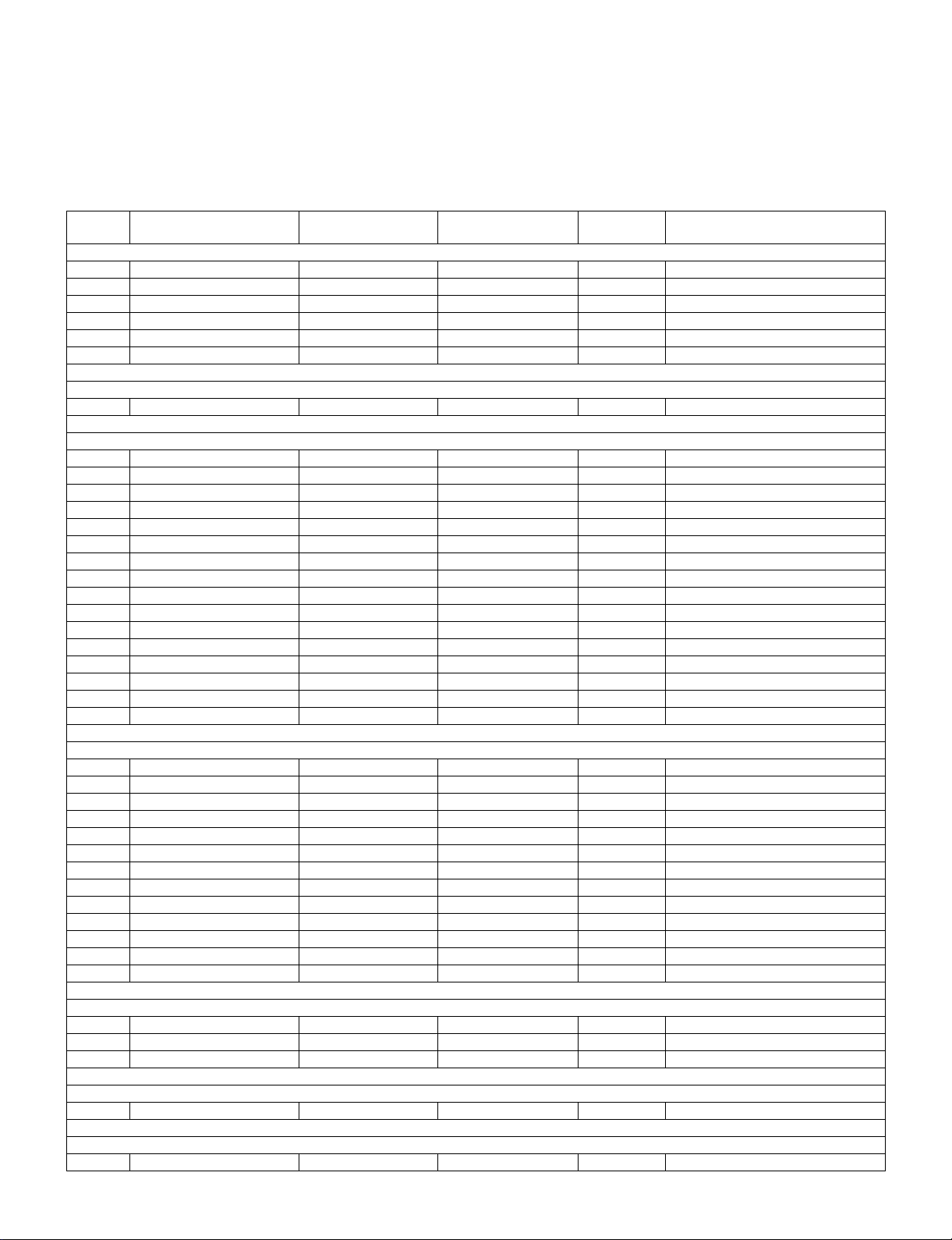
LIST OF CHANGED PARTS (LC-32D47UT)
Ref. No. Description
PRINTED WIRING BOARD ASSEMBLIES
MAIN Unit DUNTKF030FM08 DUNTKF030FM20S D Some Parts Changed
KEY Unit DUNTKF069FM03 ← ——
LED Unit DUNTKF115FM01 ← ——
POWER Unit RDENCA355WJQZ ← ——
LCD CONTROL Unit CPWBX3919TPZA — — Abolish
INVERTER Unit RDENC2540TPZZ — — Abolish
LCD PANEL (NOTE: THE PARTS HERE SHOWN ARE SUPPLIED AS AN ASSEMBLY BUT NOT INDEPENDENTLY.)
32" LCD Panel Module Unit R1LK315T3LZ94 R1LK315T3LF22Z D Change (Unit Replacement Item)
MAIN Unit
D9602 Diode — VHDRB056L40-1Y — Addition
FB2601 Ferrite Bead — RBLN-A375WJQZY — Addition
FB2602 Ferrite Bead — RBLN-A375WJQZY — Addition
FB2615 Ferrite Bead — RBLN-A375WJQZY — Addition
FB2633 Ferrite Bead — RBLN-A375WJQZY — Addition
FB2634 Ferrite Bead — RBLN-A375WJQZY — Addition
FB2635 Ferrite Bead — RBLN-A375WJQZY — Addition
FB2636 Ferrite Bead — RBLN-A375WJQZY — Addition
FB2637 Ferrite Bead — RBLN-A375WJQZY — Addition
P2602 Plug — QPLGNA349WJZZY — Addition
Q9602 Transistor — VSMCH6305++-1Y — Addition
Q9606 Transistor — VSRT1N141U/-1Y — Addition
Q9607 Transistor VSRN1903///-1Y — — Abolish
R9639 Resistor — VRS-CZ1JF104JY — Addition
R9640 Resistor — VRS-CZ1JF104JY — Addition
R9644 Resistor VRS-CZ1JF103JY — — Abolish
LC-32D47U
(S39X5LC32D47U)
LC-32D47UT
(S89B9LC32D47T)
Interchange-
ablity
Note
CABINET AND MECHANICAL PARTS
1 Front Cabinet Ass'y CCABAC254WJ32 CCABAC361WJ31 D Changed
2 Rear Cabinet Ass'y CCABBB472WJ01 CCABBB566WJ01 D Changed
6 Model Label HiNDPD304WJSA HiNDPD359WJSA D Changed
9 LCD Fix Angle-T LANGKC189WJFW LANGKC275WJFW D Changed
10 LCD Fix Angle-B LANGKC190WJFW LANGKC276WJFW D Changed
11 Power PWB Angle LANGKC191WJFW LANGKC277WJFW D Changed
12 Main PWB Angle M LANGKC192WJFW LANGKC278WJFW D Changed
13 Main PWB Angle L LANGKC193WJFW LANGKC279WJFW D Changed
14 Main PWB Angle R LANGKC194WJFW LANGKC280WJFW D Changed
29 Connecting Cord (LW) QCNW-K103WJPZ QCNW-J629WJPZ D Changed
30 Connecting Cord (LB2) QCNW-J430WJPZ QCNW-J630WJPZ D Changed
31 Connecting Cord (LB1) QCNW-J431WJQZ QCNW-J639WJQZ D Changed
45 Gascket PMLT-A594WJZZ, x4 PMLT-A594WJZZ, x5 — Addition (4→5)
SUPPLIED ACCESSORIES
X8 Operation Manual (English) TiNS-E120WJN1 TiNS-E254WJZZ D Changed
X9 Operation Manual (French) TiNS-E121WJN1 TiNS-E255WJZZ D Changed
X10 Operation Manual (Spanish) TiNS-E122WJN1 TiNS-E256WJZZ D Changed
PACKING PARTS (NOT REPLACEMENT ITEM)
S1 Packing Case SPAKCF031WJZZ SPAKCF043WJZZ D Changed
SERVICE JIGS (USER FOR SERVICING)
Connecting Cord (LW) QCNW-J276WJPZ QCNW-J832WJPZ D Changed
i
Page 3
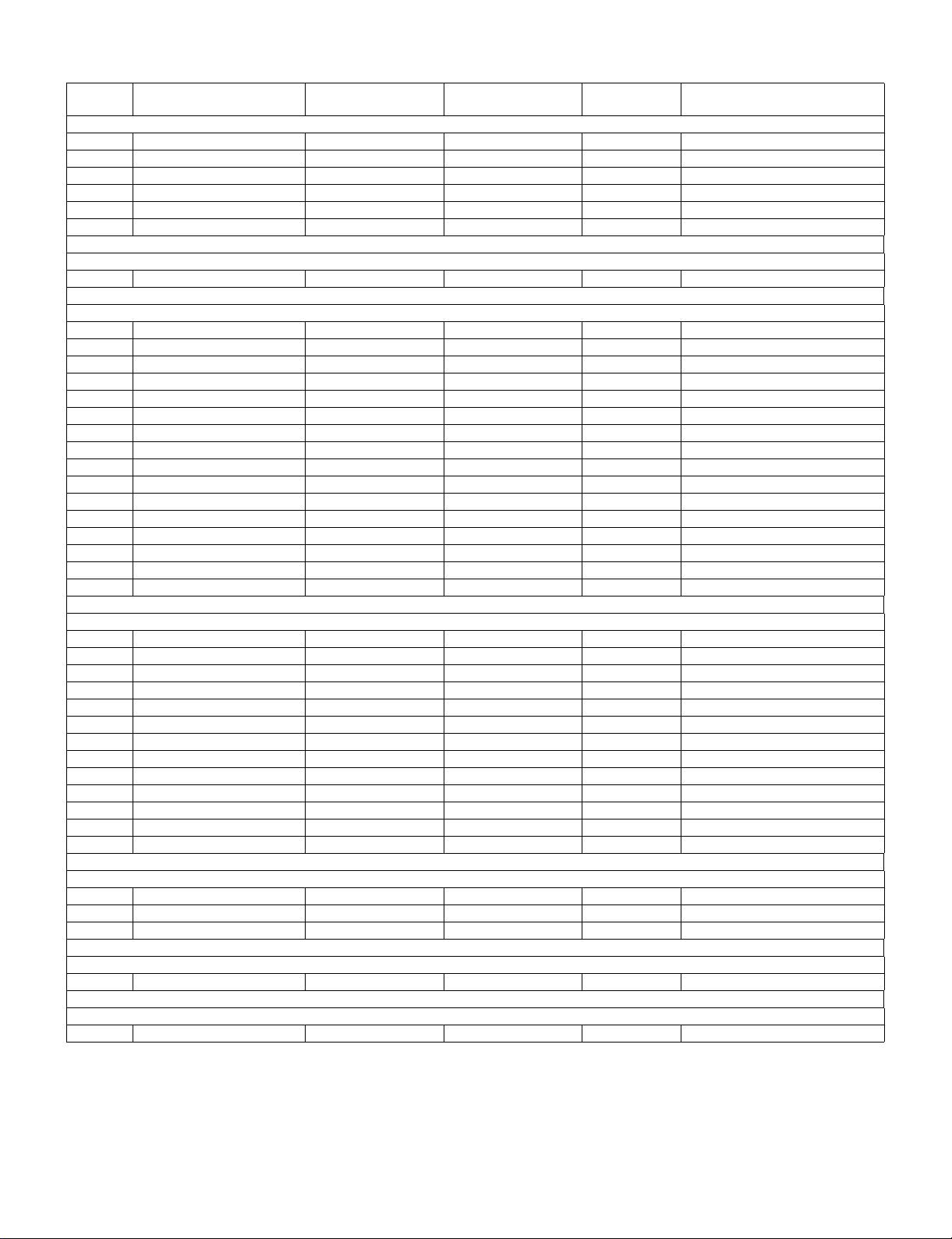
LIST OF CHANGED PARTS (LC-32SB27UT)
LC-32D47UT/LC-32SB27UT/LC-C3237UT
Ref. No. Description
PRINTED WIRING BOARD ASSEMBLIES
MAIN Unit DUNTKF030FM13 DUNTKF030FM21S D Some Parts Changed
KEY Unit DUNTKF069FM03 ← ——
LED Unit DUNTKF115FM01 ← ——
POWER Unit RDENCA355WJQZ ← ——
LCD CONTROL Unit CPWBX3919TPZA — — Abolish
INVERTER Unit RDENC2540TPZZ — — Abolish
LCD PANEL (NOTE: THE PARTS HERE SHOWN ARE SUPPLIED AS AN ASSEMBLY BUT NOT INDEPENDENTLY.)
32" LCD Panel Module Unit R1LK315T3LZ94 R1LK315T3LF22Z D Change (Unit Replacement Item)
MAIN Unit
D9602 Diode — VHDRB056L40-1Y — Addition
FB2601 Ferrite Bead — RBLN-A375WJQZY — Addition
FB2602 Ferrite Bead — RBLN-A375WJQZY — Addition
FB2615 Ferrite Bead — RBLN-A375WJQZY — Addition
FB2633 Ferrite Bead — RBLN-A375WJQZY — Addition
FB2634 Ferrite Bead — RBLN-A375WJQZY — Addition
FB2635 Ferrite Bead — RBLN-A375WJQZY — Addition
FB2636 Ferrite Bead — RBLN-A375WJQZY — Addition
FB2637 Ferrite Bead — RBLN-A375WJQZY — Addition
P2602 Plug — QPLGNA349WJZZY — Addition
Q9602 Transistor — VSMCH6305++-1Y — Addition
Q9606 Transistor — VSRT1N141U/-1Y — Addition
Q9607 Transistor VSRN1903///-1Y — — Abolish
R9639 Resistor — VRS-CZ1JF104JY — Addition
R9640 Resistor — VRS-CZ1JF104JY Addition
R9644 Resistor VRS-CZ1JF103JY — — Abolish
LC-32SB27U
(S39X5LC32D47U)
LC-32SB27UT
(S89B9LC32D47T)
Interchange-
ablity
Note
CABINET AND MECHANICAL PARTS
1 Front Cabinet Ass'y CCABAC322WJ31 CCABAC363WJ31 D Changed
2 Rear Cabinet Ass'y CCABBB472WJ01 CCABBB566WJ01 D Changed
6 Model L abel HiNDPD308WJSA HiNDPD360WJSA D Changed
9 LCD Fix Angle-T LANGKC189WJFW LANGKC275WJFW D Changed
10 LCD Fix Angle-B LANGKC190WJFW LANGKC276WJFW D Changed
11 Power PWB Angle LANGKC191WJFW LANGKC277WJFW D Changed
12 Main PWB Angle M LANGKC192WJFW LANGKC278WJFW D Changed
13 Main PWB Angle L LANGKC193WJFW LANGKC279WJFW D Changed
14 Main PWB Angle R LANGKC194WJFW LANGKC280WJFW D Changed
29 Connecting Cord (LW) QCNW-K103WJPZ QCNW-J629WJPZ D Changed
30 Connecting Cord (LB2) QCNW-J430WJPZ QCNW-J630WJPZ D Changed
31 Connecting Cord (LB1) QCNW-J431WJQZ QCNW-J639WJQZ D Changed
45 Gascket PMLT-A594WJZZ, x4 PMLT-A594WJZZ, x5 — Addition (4→5)
SUPPLIED ACCESSORIES
X8 Operation Manual (English) TiNS-E166WJN1 TiNS-E257WJZZ D Changed
X9 Operation Manual (French) TiNS-E167WJN1 TiNS-E258WJZZ D Changed
X10 Operation Manual (Spanish) TiNS-E168WJN1 TiNS-E259WJZZ D Changed
PACKING PARTS (NOT REPLACEMENT ITEM)
S1 Packing Case SPAKCF030WJZZ SPAKCF044WJZZ D Changed
SERVICE JIGS (USER FOR SERVICING)
Connecting Cord (LW) QCNW-J276WJPZ QCNW-J832WJPZ D Changed
ii
Page 4
LC-32D47UT/LC-32SB27UT/LC-C3237UT
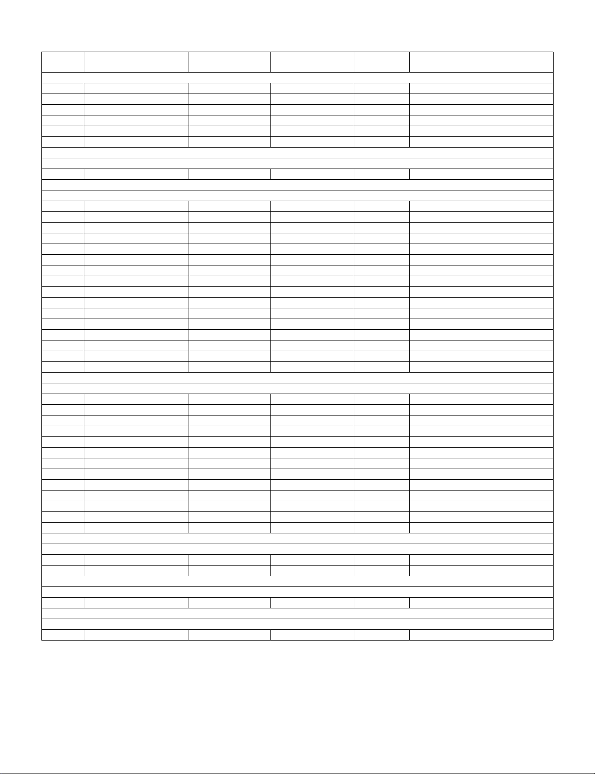
LIST OF CHANGED PARTS (LC-C3237UT)
Ref. No. Description
PRINTED WIRING BOARD ASSEMBLIES
MAIN Unit DUNTKF030FM12 DUNTKF030FM22S D Some Parts Changed
KEY Unit DUNTKF069FM03 ← ——
LED Unit DUNTKF115FM01 ← ——
POWER Unit RDENCA355WJQZ ← ——
LCD CONTROL Unit CPWBX3919TPZA — — Abolish
INVERTER Unit RDENC2540TPZZ — — Abolish
LCD PANEL (NOTE: THE PARTS HERE SHOWN ARE SUPPLIED AS AN ASSEMBLY BUT NOT INDEPENDENTLY.)
32" LCD Panel Module Unit R1LK315T3LZ94 R1LK315T3LF22Z D Change (Unit Replacement Item)
MAIN Unit
D9602 Diode — VHDRB056L40-1Y — Addition
FB2601 Ferrite Bead — RBLN-A375WJQZY — Addition
FB2602 Ferrite Bead — RBLN-A375WJQZY — Addition
FB2615 Ferrite Bead — RBLN-A375WJQZY — Addition
FB2633 Ferrite Bead — RBLN-A375WJQZY — Addition
FB2634 Ferrite Bead — RBLN-A375WJQZY — Addition
FB2635 Ferrite Bead — RBLN-A375WJQZY — Addition
FB2636 Ferrite Bead — RBLN-A375WJQZY — Addition
FB2637 Ferrite Bead — RBLN-A375WJQZY — Addition
P2602 Plug — QPLGNA349WJZZY — Addition
Q9602 Transistor — VSMCH6305++-1Y — Addition
Q9606 Transistor — VSRT1N141U/-1Y — Addition
Q9607 Transistor VSRN1903///-1Y — — Abolish
R9639 Resistor — VRS-CZ1JF104JY — Addition
R9640 Resistor — VRS-CZ1JF104JY — Addition
R9644 Resistor VRS-CZ1JF103JY — — Abolish
LC-C3237U
(S39X5LC32D47U)
LC-C3237UT
(S89B9LC32D47T)
Interchange-
ability
Note
CABINET AND MECHANICAL PARTS
1 Front Cabinet Ass'y CCABAC254WJ33 CCABAC361WJ32 D Changed
2 Rear Cabinet Ass'y CCABBB472WJ01 CCABBB566WJ01 D Changed
6 Model Label HiNDPD302WJSA HiNDPD361WJSA D Changed
9 LCD Fix Angle-T LANGKC189WJFW LANGKC275WJFW D Changed
10 LCD Fix Angle-B LANGKC190WJFW LANGKC276WJFW D Changed
11 Power PWB Angle LANGKC191WJFW LANGKC277WJFW D Changed
12 Main PWB Angle M LANGKC192WJFW LANGKC278WJFW D Changed
13 Main PWB Angle L LANGKC193WJFW LANGKC279WJFW D Changed
14 Main PWB Angle R LANGKC194WJFW LANGKC280WJFW D Changed
29 Connecting Cord (LW) QCNW-K103WJPZ QCNW-J629WJPZ D Changed
30 Connecting Cord (LB2) QCNW-J430WJPZ QCNW-J630WJPZ D Changed
31 Connecting Cord (LB1) QCNW-J431WJQZ QCNW-J639WJQZ D Changed
45 Gascket PMLT-A594WJZZ, x4 PMLT-A594WJZZ, x5 — Addition (4→5)
SUPPLIED ACCESSORIES
X8 Operation Manual (English ) TiNS-E164WJN1 TiNS-E260WJZZ D Changed
X10 Operation Manual (Spanish) TiNS-E165WJN1 TiNS-E261WJZZ D Changed
PACKING PARTS (NOT REPLACEMENT ITEM)
S1 Packing Case SPAKCE939WJZZ SPAKCF045WJZZ D Changed
SERVICE JIGS (USER FOR SERVICING)
Connecting Cord (LW) QCNW-J276WJPZ QCNW-J832WJPZ D Changed
iii
Page 5

Interchangeability
NEW OLD
NEW OLDX
LC-32D47UT/LC-32SB27UT/LC-C3237UT
A: Completely interchangeable C:
Interchangeable from
B:
OLD to NEW
OLD = NEW
OLD NEW
Interchangeable from
NEW to OLD
D: Not interchangeable
iv
Page 6

LC-32D47UT/LC-32SB27UT/LC-C3237UT
LC32D47UT
SAFETY PRECAUTION
ServiceManual
IMPORTANT SERVICE SAFETY PRECAUTION
Service work should be performed only by qualified service technicians who are thoroughly familiar with all safety checks and the
servicing guidelines which follow:
WARNING
1. For continued safety, no modification of any circuit should be
attempted.
2. Disconnect AC power before servicing.
CAUTION: FO R C O N T I N U E D PROTECTION
AGAINST A RISK OF FIRE REPLACE ONLY WITH
SAME TYPE FUSE.
F701 (250V 5A)
• Use an AC voltmeter having with 5000 ohm per volt, or higher, sensitivity or measure the AC voltage drop across the resistor.
• Connect the resistor connection to all exposed metal parts having a
return to the chassis (antenna, metal cabinet, screw heads, knobs
and control shafts, escutcheon, etc.) and measure the AC voltage
drop across the resistor.
All checks must be repeated with the AC cord plug connection
reversed. (If necessary, a nonpolarized adaptor plug must be used
only for the purpose of completing these checks.)
Any reading of 0.75 Vrms (this corresponds to 0.5 mA rms AC.) or
more is excessive and indicates a potential shock hazard which
must be corrected before returning the monitor to the owner.
F721 (250V 2A)
F4732 (250V 2A)
DVM
BEFORE RETURNING THE RECEIVER (Fire & Shock Hazard)
Before returning the receiver to the user, perform the following
safety checks:
3. Inspect all lead dress to make certain that leads are not pinched,
and check that hardware is not lodged between the chassis and
other metal parts in the receiver.
4. Inspect all protective devices such as non-metallic control knobs,
insulation materials, cabinet backs, adjustment and compartment
covers or shields, isolation resistor-capacitor networks, mechanical
insulators, etc.
5. To be sure that no shock hazard exists, check for leakage current in
the following manner.
• Plug the AC cord directly into a 120 volt AC outlet.
• Using two clip leads, connect a 1.5k ohm, 10 watt resistor paralleled by a 0.15µF capacitor in series with all exposed metal cabinet
parts and a known earth ground, such as electrical conduit or electrical ground connected to an earth ground.
///////////////////////////////////////////////////////////////////////////////////////////////////////////////////////////////////////////////////////////////////////////////////////////////////////////////////////////////////////////
TO EXPOSED
METAL PARTS
AC SCALE
1.5k ohm
10W
0.15µF
TEST PROBE
CONNECT TO
KNOWN EARTH
GROUND
SAFETY NOTICE
Many electrical and mechanical parts in LCD color television have
special safety-related characteristics.
These characteristics are often not evident from visual inspection, nor
can protection afforded by them be necessarily increased by using
replacement components rated for higher voltage, wattage, etc.
Replacement parts which have these special safety characteristics are
identified in this manual; electrical components having such features
are identified by " " and shaded areas in the Replacement Parts List
and Schematic Diagrams.
///////////////////////////////////////////////////////////////////////////////////////////////////////////////////////////////////////////////////////////////////////////////////////////////////////////////////////////////////////////
For continued protection, replacement parts must be identical to those
used in the original circuit.
The use of a substitute replacement parts which do not have the same
safety characteristics as the factory recommended replacement parts
shown in this service manual, may create shock, fire or other hazards.
v
Page 7

LC-32D47UT/LC-32SB27UT/LC-C3237UT
PRECAUTIONS A PRENDRE LORS DE LA REPARATION
Ne peut effectuer la réparation qu' un technicien spécialisé qui s'est parfaitement accoutumé à toute vérification de sécurité et aux
conseils suivants.
•
AVERTISSEMENT
1.
N'entreprendre aucune modification de tout circuit. C'est dangereux.
2.
Débrancher le récepteur avant toute réparation.
PRECAUTION: POUR LA PROTECTION CONTINUE CONTRE LES RISQUES D'INCENDIE,
REMPLACER LE FUSIBLE
F701 (250V 5A)
F721 (250V 2A)
F4732 (250V 2A)
VERIFICATIONS CONTRE L'INCEN-DIE ET LE
CHOC ELECTRIQUE
Avant de rendre le récepteur à l'utilisateur, effectuer les vérifications suivantes.
3.
Inspecter tous les faisceaux de câbles pour s'assurer que les fils
ne soient pas pincés ou qu'un outil ne soit pas placé entre le châssis et les autres pièces métalliques du récepteur.
4.
Inspecter tous les dispositifs de protection comme les boutons de
commande non-métalliques, les isolants, le dos du coffret, les couvercles ou blindages de réglage et de compartiment, les réseaux
de résistancecapacité, les isolateurs mécaniques, etc.
5.
S'assurer qu'il n'y ait pas de danger d'électrocution en vérifiant la
fuite de courant, de la facon suivante:
•
Brancher le cordon d'alimentation directem-ent à une prise de courant de 120V. (Ne pas utiliser de transformateur d'isolation pour
cet essai).
A l'aide de deux fils à pinces, brancher une résistance de 1.5 kΩ
10 watts en parallèle avec un condensateur de 0.15µF en série
avec toutes les pièces métalliques exposées du coffret et une terre
connue comme une conduite électrique ou une prise de terre
branchée à la terre.
•
Utiliser un voltmètre CA d'une sensibilité d'au moins 5000Ω/V pour
mesurer la chute de tension en travers de la résistance.
•
Toucher avec la sonde d'essai les pièces métalliques exposées qui
présentent une voie de retour au châssis (antenne, coffret métallique, tête des vis, arbres de commande et des boutons, écusson,
etc.) et mesurer la chute de tension CA en-travers de la résistance.
Toutes les vérifications doivent être refaites après avoir inversé la
fiche du cordon d'alimentation. (Si nécessaire, une prise
d'adpatation non polarisée peut être utilisée dans le but de terminer ces vérifications.)
La tension de pointe mesurèe ne doit pas dépasser 0.75V (correspondante au courant CA de pointe de 0.5mA).
Dans le cas contraire, il y a une possibilité de choc électrique qui
doit être supprimée avant de rendre le récepteur au client.
DVM
ECHELLE CA
1.5k ohm
10W
µ
F
0.15
SONDE D'ESSAI
AUX PIECES
METALLIQUES
EXPOSEES
/////////////////////////////////////////////////////////////////////////////////////////////////////////////////////////////////////////////////////////////////////////////////////////////////////////////////////////////////////////////
BRANCHER A UNE
TERRE CONNUE
AVIS POUR LA SECURITE
De nombreuses pièces, électriques et mécaniques, dans les téléviseur ACL présentent des caractéristiques spéciales relatives à la sécurité, qui ne sont souvent pas évidentes à vue. Le degré de protection ne peut pas être nécessairement augmentée en utilisant des
pièces de remplacement étalonnées pour haute tension, puissance,
etc.
Les pièces de remplacement qui présentent ces caractéristiques sont
identifiées dans ce manuel; les pièces électriques qui présentent ces
particularités sont identifiées par la marque " " et hachurées dans la
liste des pièces de remplacement et les diagrammes schématiques.
/////////////////////////////////////////////////////////////////////////////////////////////////////////////////////////////////////////////////////////////////////////////////////////////////////////////////////////////////////////////
Pour assurer la protection, ces pièces doivent être identiques à celles
utilisées dans le circuit d'origine. L'utilisation de pièces qui n'ont pas
les mêmes caractéristiques que les pièces recommandées par l'usine,
indiquées dans ce manuel, peut provoquer des électrocutions, incendies, radiations X ou autres accidents.
vi
Page 8

LC-32D47UT/LC-32SB27UT/LC-C3237UT
PRECAUTIONS FOR USING LEAD-FREE SOLDER
Employing lead-free solder
• “PWBs” of this model employs lead-free solder. The LF symbol indicates lead-free solder, and is attached on the PWBs and service manuals. The
alphabetical character following LF shows the type of lead-free solder.
Example:
Indicates lead-free solder of tin, silver and copper. Indicates lead-free solder of tin, silver and copper.
Using lead-free wire solder
• When fixing the PWB soldered with the lead-free solder, apply lead-free wire solder. Repairing with conventional lead wire solder may cause damage or accident due to cracks.
As the melting point of lead-free solder (Sn-Ag-Cu) is higher than the lead wire solder by 40 °C, we recommend you to use a dedicated soldering
bit, if you are not familiar with how to obtain lead-free wire solder or soldering bit, contact our service station or service branch in your area.
Soldering
• As the melting point of lead-free solder (Sn-Ag-Cu) is about 220 °C which is higher than the conventional lead solder by 40 °C, and as it has poor
solder wettability, you may be apt to keep the soldering bit in contact with the PWB for extended period of time. However, Since the land may be
peeled off or the maximum heat-resistance temperature of parts may be exceeded, remove the bit from the PWB as soon as you confirm the
steady soldering condition.
Lead-free solder contains more tin, and the end of the soldering bit may be easily corroded. Make sure to turn on and off the power of the bit as
required.
If a different type of solder stays on the tip of the soldering bit, it is alloyed with lead-free solder. Clean the bit after every use of it.
When the tip of the soldering bit is blackened during use, file it with steel wool or fine sandpaper.
• Be careful when replacing parts with polarity indication on the PWB silk.
Lead-free wire solder for servicing
PARTS CODE
ZHNDAi123250E BL J φ0.3mm 250g (1roll)
ZHNDAi126500E BK J φ0.6mm 500g (1roll)
ZHNDAi12801KE BM J φ1.0mm 1kg (1roll)
PRICE
RANK
PART
DELIVERY
DESCRIPTION
vii
Page 9

LC32D47UT
CHAPTER 1. OVERALL WIRING DIAGRAM
[1] OVERALL WIRING DIAGRAM
㪨㪚㪥㪮㪄㪡㪍㪊㪐㪮㪡㪨㪱
㪨㪚㪥㪮㪄㪡㪈㪎㪈㪮㪡㪨㪱
ServiceManual
㪊㪉㩹㩷㪣㪚㪛㩷㪧㪸㫅㪼㫃
㪈㪊㪍㪍㬍㪎㪍㪏㵘㪮㪯㪞㪘
㪈㪉
䇼㪧㪛䇽
㪋㩷㪈
䇼㪣㪙㪈䇽
LC-32D47UT/LC-32SB27UT/LC-C3237UT
㪈
㪨㪚㪥㪮㪄㪡㪈㪎㪇㪮㪡㪨㪱
㪢㪜㪰㩷㪬㫅㫀㫋
䇼㪢㪤䇽
㪋
㪈
䇼㪢㪤䇽
㪟㪛㪤㪠
㪧㪚㩷㪘㫌㪻㫀㫆㩷㪠㪥
㪭㪆㪣㪩
㪬㪪㪙
㪘㫅㪸㫃㫆㪾㩷㪩㪞㪙
㪈㪉㵘㵘㵘㪈
䇼㪧㪛䇽
㪼㫏㪺㪼㫇㫋㩷㪽㫆㫉
㪪㪙㪉㪎㪬㪫
䌈䌄䌍䌉
㪛㫀㪾㫀㫋㪸㫃㩷㪘㫌㪻㫀㫆㩷㪦㪬㪫
㪪㪄㪭㪠㪛㪜㪦
㪚㪌
㪤㪘㪠㪥㩷㪬㫅㫀㫋
㪣㪆㪩㩷㪦㪬㪫
㪍㩷㪈
䇼㪣㪙㪈䇽
㪈㪌㵘㵘㪈
䇼㪣㪧䇽
䇼㪣㪮䇽
㪛㪛㪩
㪫㪬㪥㪜㪩
䇼㪩㪘䇽
䇼㪪㪧䇽
㪈㩷㩷㩷㩷㩷㩷㩷㪈㪇 㪈㩷㩷㪋
㪋㪈
㪈
㪈㪋
䇼㪣㪙㪉䇽
㪍
㪨㪚㪥㪮㪄㪡㪍㪊㪇㪮㪡㪧㪱
㪈
䇼㪧㪣䇽
㪨㪚㪥㪮㪄㪡㪍㪉㪐㪮㪡㪧㪱
㪈
㪧㪦㪮㪜㪩
㪬㫅㫀㫋
㪈㪋
㪈
㪠㪥㪭
㪬㫅㫀㫋
㪋
㪈
㪨㪚㪥㪮㪄㪡㪈㪎㪊㪮㪡㪨㪱
䇼㪣㪮䇽
㪊㪇㩷㩷㩷㩷㩷㩷㪈
㪎
㪈
䇼㪩㪘䇽
㪣㪜㪛㩷㪬㫅㫀㫋
㪣㪚㪛㩷㪚㫆㫅㫋㩷㪬㫅㫀㫋
㪨㪚㪥㪮㪄㪡㪈㪎㪋㪮㪡㪨㪱
1 – 1
Page 10

LC-32D47UT/LC-32SB27UT/LC-C3237UT
LC32D47UT
CHAPTER 2. SCHEMATIC DIAGRAM
[1] SCHEMATIC DIAGRAM
TO_MAIN13(POWER1)
J
TO_MAIN8(CPU)
LV0OUT0M
LV0OUT0P
LV0OUT1M
LV0OUT1P
I
LV0OUT2M
LV0OUT2P
LV0CKOM
LV0CKOP
LV0OUT3M
LV0OUT3P
H
G
F
TO_MAIN7(UCOM)
E
TO_MAIN11(EXBUS)
D
TO_MAIN8(CPU)
C
TO_MAIN12(CONN)
B
A
PNL_12V
ROMSEL0
O_S_SET
DET_PNL12V
ERR_PNL
DET_SYNC
SHIP_EN
SHIP_EN
PNL_EN
PNL_PWM
PNL_PWM2
I2C_SCL
I2C_SDA
D3.3V
FRAME
TEMP3
TEMP2
TEMP1
5V
L_R
U_D
VON
ServiceManual
MAIN6 (PANEL) [6/14]
MAIN UNIT 6/14
R2639
100K
DUNTKF030WE
(PWBXF030WJ)
FB2604
A375WJQZ
FB2605
A375WJQZ
FB2606
A375WJQZ
FB2607
A375WJQZ
FB2608
A375WJQZ
FB2621
A074WJ
FB2622
A074WJ
FB2623
A074WJ
FB2624
A074WJ
FB2625
A074WJ
FB2626
A074WJ
FB2627
A074WJ
FB2628
A074WJ
FB2629
A074WJ
FB2630
A074WJ
FB2631
A074WJ
FB2613
A074WJ
FB2619
A074WJ
FB2620
A074WJ
FB2609
A204WJ
FB2618
A074WJ
C2606
0.1u
CZB
*FB2602
A375WJQZ
*FB2601
A375WJQZ
*FB2615
A375WJQZ
*FB2633
A375WJQZ
*FB2634
A375WJQZ
*FB2635
A375WJQZ
*FB2636
A375WJQZ
*FB2637
A375WJQZ
LW
41
40
39
38
37
36
35
34
33
32
31
30
29
28
27
26
25
24
23
22
21
20
19
18
17
16
15
14
13
12
11
10
9
8
7
6
5
4
3
2
1
LB1
6
5
4
3
2
1
LP
15
14
13
12
11
10
9
8
7
6
5
4
3
2
1
GND
TA1-
TA1+
TB1-
TB1+
TC1-
TC1+
GND
TCLK1-
TCLK1+
TD1-
TD1+
TE1-
TE1+
GND
TA2-
TA2+
TB2-
TB2+
TC2-
TC2+
GND
TCLK2-
TCLK2+
TD2-
TD2+
TE2-
TE2+
GND
LVDS_SEL
R/L
U/D
HV_MODE
ROMSEL1
ROMSEL0
TEMP3
TEMP2
TEMP1
PE
OS_EN
SHIP_EN
P2603
NA340WJ
OFL2
BRT
ERR
OFL1
VON
GND
*P2602
NA349WJ
DET
LCD_EN
VCOM_SDA
VCOM_SCL
VCOM_WP
COND_DET
TEST_MODE
GND
GND
GND
GND
VCC
VCC
VCC
VCC
P2601
WA659WJQZ
TO LCDCONT
TO LCDCONT
TO INV
->
<-
->
->
<-
->
<->
<->
->
->
->
L2606
FA154WJ
1
L2601
FA154WJ
1
3
2
4
L2602
FA154WJ
1
3
2
4
3
2
4
L2607
FA154WJ
1
3
2
4
L2608
FA154WJ
1
3
2
4
R2606
0
R2607
0
R2613
R2614
0
0
100K
R2636
1234567
*IC2602
R2601
8
M62332FP
*C2609
0.1u
10V
R2602
22K
1234567
5.0
8
7
6
5
22K
8
R2603
F
22K
Q2603
KRC404E
AO1
1
Vcc
NC
2
SCL
NC
3
SDA
NC
4
GND
R2635
10K
*R2621
10K
123456789
10 11 12 13 14 15 16 17 18 19 20 21
2 – 1
Page 11

LC-32D47UT/LC-32SB27UT/LC-C3237UT
D9611
EXA512WJ
4V
1/2W
TWF
22k
Q9609
RN2408
[13/14]
L9604
100uH
PA903WJ
0.7A,0.5
KZA510WJPZ
R9631
1
1/2W
TWF
22k
3
Q9608
RN2408
A1.8V 220mA
C9638
100u
4V
ARC
C9631
1u
10V
KZA520WJQZ
D1.8V 380mA
47k
D9618
MA111G
C9633
10u 16V
R9633
1
D9619
MA111G
1
2
TWF
TO MAIN1(TUNER)
A9V
A5V
A3.3V
TO MAIN2(A_TERM)
A9V
5V
A5V
D3.3V
TO MAIN3(AMP_IF)
UR13V
A9V
A5V
D3.3V
TO MAIN4(AMP)
UR13V
TO MAIN14(SP_IF)
5V
D3.3V
BU3.3V
TO MAIN5(HDMI_SW1)
5V
BU3.3V
D3.3V
TO MAIN6(PANEL)
5V
1/2W
D3.3V
TO MAIN10(EPROM)
1
47k
2
BU3.3V
D3.3V
TO MAIN11(EXBUS)
D3.3V
TO MAIN12(CONN)
D3.3V
BU3.3V
BU5V
5V
TO_MAIN9(DDR)
D1.8V
120mA
TO MAIN8(CPU)
BU3.3V
PNL_ON
D3.3V
A1.8V
D1.8V
5V
D1.2V
A3.3V
400mA
380mA
300mA
USB 500mA
1030mA
180mA
MAIN13 (POWER)
J
PD
I
H
G
F
E
TO MAIN7(UCOM)
D
C
TO MAIN3(AMP_IF)
TO MAIN6(PANEL)
B
TO MAIN8(CPU)
A
MAIN UNIT 13/14
DUNTKF030WE08
(PWBXF030WJ)
P9601
NA181WJ
To Power Unit
UR13V
UR13V
UR13V
UR13V
GND
GND
GND
GND
AC_DET/NC
PS_ON
BU5V
PNL_ON
*Q9602
MCH6305
123
SMPOWHOLD
CZ
VS
D3.3V
BU3.3V
AC_DET
DET_13V
SMPOW
AC_DET
PNL_12V
456
*R9639
100K
RT1N141U
5V
1
2
3
4
5
6
7
8
9
10
11
12
*R9640
100K
CZ
IC9601
TCR5SB33
*Q9606
VHD
*D9602
RB056L40
C9601
1u 10V
KZA520WJQZ
C9602
4.7u
KZA403WJPZ
R9607
47K
D9601
D9615
D9613
*FB9610
A074WJ
6.3V
FB9601
A375WJQZ
FB9602
A375WJQZ
FB9603
A375WJQZ
FB9604
A375WJQZ
FB9605
A375WJQZ
FB9606
A375WJQZ
FB9607
A375WJQZ
FB9611
A375WJQZ
*FB9608
A074WJ
FB9609
A074WJ
*FB9612
A375WJQZ
3
4
F
VHD
MA111G
VHD
MA111G
VHD
MA111G
GND_B
ON
NC
R9611
4.7K CZ
*R9636
27K
CZ
*R9637
10KCZF
*R9645
1K
CZ
R9605
C9603
0.01u
CZB
25V
5.6K
C9607
CZB
7EN8
SS
1000P
COMP
5FB6
0.796
R9608
10K
F
R9609
47K
IC9602
R9610
6.8K
F
LV5893M
GND
Vin
1BS2
C9604
0.1u
25V
CYB
R9602
39
C9606
10u
KZA510WJPZ
1
*R9646
VHD
0
CZ
D9614
MA111G
Q9601
RN4982
12 3
VIn2GND
Vout
5
3SW4
L9601
5.1V 1440mA
15uH
PA898WJ
VHD
1.9A,77m
C9609
10u
16V
KZA510WJPZ
D9604
D1FH3
CZ
Q9603
RN4982
456
D9605
MA111G
12 3
C9610
1u
KZA520WJQZ
C9611
10u
16V
KZA510WJPZ
VHD
R9612
4.7K
CZ
10V
D9607
MA111G
CZB
C9608
R9601
10K
R9603
1000P
R9606
4.7
456
C9605
0.01u
25V
CZ
1K
CZ
D9603
MA111G
16V
R9613
4.7K
CZ
D9606
EXA523WJ
5.6V
R9614
VS
10K
Q9605
KTC3875SG
D1.2V
IC9603
PQ1LAX95
GND3On
Vin5Vout
4
KZA520WJQZ
F
R9615
5.6K CZ
1
2
Vadj
C9612
1u
10V
Q9604
RT1N141U
VS
D9608
1PS226
3
R9616
3.9K
CZ
R9617
33K
R9641
2.2K
R9622
4.7K
R9625
C9621
0.01u
C9615
CZB
CZB
25V
7EN8
SS
4700P
COMP
10K
F
25V
5FB6
0.796
R9627
27K
R9629
4.7K
F
3.32V 700mA
IC9605
LV5893M
GND
C9618
10u
16V
KZA403WJPZ
8
SS
1BS2
C9634
4.7u
CZB
7
Vin
3SW4
CZB
C9622
1000P
IC9608
PQ1LA335
1
2
3
6.3V
R9620
4.7K
C9619
4700P
25V
0.796
NC
5FB6
EN
COMP
R9623
4.7
Nr
GND
On
R9624
10K
F
IC9604
D9610
*IC9606
R9626
5.6K
L9603
15uH
PA898WJ
D1FS4A
VHD
Vout
Vin
PQ1LA185
R9628
330
F
1.9A,77m
C9624
10u
16V
KZA510WJPZ
5
4
C9629
0.1u
10V
CZB
C9626
10u
16V
KZA510WJPZ
2
GND3On
Vin5Vout
4
IC9607
MM3441JF
CE
5
Sub
6
7
Vin
Vadj
D9612
MA111G
*C9628
0.01u
25V
CZB
1
C9630
1u
10V
KZA520WJQZ
NC
4
GND
3
NC
2
Vout
1
C9613
0.01u
C9616
0.1u
25V
CZB
CYB
R9619
39
KZA510WJPZ
C9632
0.01u
CZB
25V
LV5893M
R9632
D1.26V 680mA
16V
C9627
10u
KZA510WJPZ
R9630
16V
1
TWF
1/2W
1
3
Vin
C9614
0.1u
1BS2
25V
CYB
R9618
2
39
C9617
1
J
10u
16V
KZA510WJPZ
3SW4
GND
D1FS4A
D9609
VHD
CIL
L9602
15uH
PA898WJ
1.9A,77m
C9623
10u
16V
KZA510WJPZ
C9625
10u
KZA510WJPZ
123456789
10 11 12 13 14 15 16 17 18 19 20 21
2 – 2
Page 12

LC-32D47UT/LC-32SB27UT/LC-C3237UT
2 – 3
Page 13

PartsGuide
LC-32D47UT/LC-32SB27UT/LC-C3237UT
PARTS GUIDE
No. S89B9LC32D47T
LCD COLOUR TELEVISION
LC-32D47UT
LC-32SB27UT
Note:
The reference numbers on the PWB
are arranged in alphabetical order.
[1] PRINTED WIRING BOARD
ASSEMBLIES
[2] LCD PANEL
[3] DUNTKF030FM20S/21S/22S (MAIN
Unit)
[4] CABINET AND MECHANICAL
PARTS
MODELS
CONTENTS
[5] SUPPLIED ACCESSORIES
[6] PACKING PARTS (NOT
[7] SERVICE JIGS (USER FOR
LC-C3237UT
REPLACEMENT ITEM)
SERVICING)
INDEX
Parts marked with " " are important for maintaining the safety of the set. Be sure to replace these
parts with specified ones for maintaining the safety and performance of the set.
This document has been published to be used
for after sales service only.
The contents are subject to change without notice.
Page 14

LC-32D47UT/LC-32SB27UT/LC-C3237UT
NO. PARTS CODE
PRICE
RANK
NEW
MARK
PART
DELIVERY
[1] PRINTED WIRING BOARD ASSEMBLIES
N DUNTKF030FM20S BX N X MAIN Unit (LC-32D47UT)
N DUNTKF030FM21S BX N X MAIN Unit (LC-32SB27UT)
N DUNTKF030FM22S BX N X MAIN Unit (LC-C3237UT)
N DUNTKF069FM03 AH N X KEY Unit
N DUNTKF115FM01 AM X LED Unit
N RDENCA355WJQZ BM N X POWER Unit
[2] LCD PANEL
N R1LK315T3LF22Z CZ N X 32" LCD Panel Mudule Unit (CMO Module)
[3] DUNTKF030FM20S/21S/22S (MAIN Unit)
D9602 VHDRB056L40-1Y AC X Diode
FB2601 RBLN-A375WJQZY AA J Ferrite Bead
FB2602 RBLN-A375WJQZY AA J Ferrite Bead
FB2615 RBLN-A375WJQZY AA J Ferrite Bead
FB2633 RBLN-A375WJQZY AA J Ferrite Bead
FB2634 RBLN-A375WJQZY AA J Ferrite Bead
FB2635 RBLN-A375WJQZY AA J Ferrite Bead
FB2636 RBLN-A375WJQZY AA J Ferrite Bead
FB2637 RBLN-A375WJQZY AA J Ferrite Bead
P2602 QPLGNA349WJZZY AD X Plug
Q9602 VSMCH6305++-1Y AC X Transistor
Q9606 VSRT1N141U/-1Y AA X Transistor
R9639 VRS-CZ1JF104JY AA J Resistor 100k 1/16W Metal Oxide
R9640 VRS-CZ1JF104JY AA J Resistor 100k 1/16W Metal Oxide
[4] CABINET AND MECHANICAL PARTS
1 CCABAC361WJ31 BG N X Front Cabinet Ass'y (LC-32D47UT)
1 CCABAC363WJ31 BH N X Front Cabinet Ass'y (LC-32SB27UT)
1 CCABAC361WJ32 BH N X Front Cabinet Ass'y (LC-C3237UT)
2 CCABBB566WJ01 BG N X Rear Cabinet Ass'y
6 HINDPD359WJSA AD N X Model Label (LC-32D47UT)
6 HINDPD360WJSA AD N X Model Label (LC-32SB27UT)
6 HINDPD361WJSA AD N X Model Label (LC-C3237UT)
9 LANGKC275WJFW AP N X LCD Fix Angle-T
10 LANGKC276WJFW AR N X LCD Fix Angle-B
11 LANGKC277WJFW AF N X Power PWB Angle
12 LANGKC278WJFW AF N X Main PWB Angle M
13 LANGKC279WJFW AG N X Main PWB Angle L
14 LANGKC280WJFW AG N X Main PWB Angle R
29 QCNW-J629WJPZ AV N X Connecting Cord (LW)
30 QCNW-J630WJPZ AK N X Connecting Cord (LB2)
31 QCNW-J639WJQZ AF N X Connecting Cord (LB1)
45 PMLT-A594WJZZ AF X Gascket, x5
[5] SUPPLIED ACCESSORIES
X8 TINS-E254WJZZ AE N X Operation Manual (English) (LC-32D47UT)
X8 TINS-E257WJZZ AE N X Operation Manual (English) (LC-32SB27UT)
X8 TINS-E260WJZZ AE N X Operation Manual (English) (LC-C3237UT)
X9 TINS-E255WJZZ AE N X Operation Manual (French) (LC-32D47UT)
X9 TINS-E258WJZZ AE N X Operation Manual (French) (LC-32SB27UT)
X10 TINS-E256WJZZ AE N X Operation Manual (Spanish) (LC-32D47UT)
X10 TINS-E259WJZZ AE N X Operation Manual (Spanish) (LC-32SB27UT)
X10 TINS-E261WJZZ AE N X Operation Manual (Spanish) (LC-C3237UT)
[6] PACKING PARTS (NOT REPLACEMENT ITEM)
S1 SPAKCF043WJZZ - N - Packing Case (LC-32D47UT)
S1 SPAKCF044WJZZ - N - Packing Case (LC-32SB27UT)
S1 SPAKCF045WJZZ - N - Packing Case (LC-C3237UT)
[7] SERVICE JIGS (USER FOR SERVICING)
N QCNW-J832WJPZ N J L=700mm, Main-LCD Panel Module Unit(LW)
DESCRIPTION
2
Page 15

LC-32D47UT/LC-32SB27UT/LC-C3237UT
Page 16

LC-32D47UT/LC-32SB27UT/LC-C3237UT
COPYRIGHT 2009 BY SHARP CORPORATION
©
ALL RIGHTS RESERVED.
No part of this publication may be reproduced,
stored in a retrieval system, or transmitted in
any form or by any means, electronic, mechanical,
photocopying, recording, or otherwise, without
prior written permission of the publisher.
Aug. 2009
SH. KY
SHARP CORPORATION
AV Systems Group
CS Promotion Center
Yaita, Tochigi, 329-2193, Japan
 Loading...