

Page 1
LC-26GA4D
LC-26GA4U
SERVICE MANUAL
S64V2LC26GA4U
LCD COLOR TELEVISION
LC-26GA4D
MODELS
In the interests of user-safety (Required by safety regulations in some countries) the set should be restored to its original condition and only parts identical to those specified should be used.
CONTENTS
» IMPORTANT SERVICE SAFETY PRECAUTION.......................................................................................2
» SPECIFICATIONS ......................................................................................................................................5
» OPERA TION MANUAL ...............................................................................................................................6
» DIMENSIONS ...........................................................................................................................................13
» REMOVING OF MAJOR PARTS..............................................................................................................14
» ADJUSTMENT PROCEDURE..................................................................................................................18
» TROUBLESHOOTING T ABLE .................................................................................................................36
» OVERALL WIRING DIAGRAM/CHASSIS LAYOUT.................................................................................46
» SYSTEM BLOCK DIAGRAM ....................................................................................................................48
» MAIN BLOCK DIAGRAM..........................................................................................................................50
» CPU BLOCK DIAGRAM ...........................................................................................................................52
» AV BLOCK DIAGRAM ..............................................................................................................................56
» POWER BLOCK DIAGRAM .....................................................................................................................58
» DESCRIPTION OF SCHEMATIC DIAGRAM ...........................................................................................62
» SCHEMATIC DIAGRAM ...........................................................................................................................63
» PRINTED WIRING BOARD ASSEMBLIES........................................................................................... 146
» PARTS LIST........................................................................................................................................... 182
» PACKING OF THE SET......................................................................................................................... 221
LC-26GA4U
Page
SHARP CORPORATION
This document has been published to be used for
after sales service only.
The contents are subject to change without notice.
Page 2
LC-26GA4D
1
1
LC-26GA4U
IMPORTANT SERVICE SAFETY PRECAUTION
Ë
Service work should be performed only by qualified service technicians who are thoroughly familiar with all safety checks and the servicing guidelines which follow:
WARNING
1. For continued safety, no modification of any circuit
should be attempted.
2. Disconnect AC power before servicing.
CAUTION: FOR CONTINUED
PROTECTION AGAINST A RISK OF
FIRE REPLACE ONLY WITH SAME
TYPE FUSE.
F701 (3.15A, 250V), F702 (3.15A,
A V
250V), F703 (2A, 250V), F705 (1A,
DC450V), F706 (5A, 250V), F707 (5A,
250V)
BEFORE RETURNING THE RECEIVER
(Fire & Shock Hazard)
Before returning the receiver to the user, perform
the following safety checks:
1. Inspect all lead dress to make certain that leads are
not pinched, and check that hardware is not lodged
between the chassis and other metal parts in the
receiver.
2. Inspect all protective devices such as non-metallic
control knobs, insulation materials, cabinet backs,
adjustment and compartment covers or shields,
isolation resistor-capacitor networks, mechanical
insulators, etc.
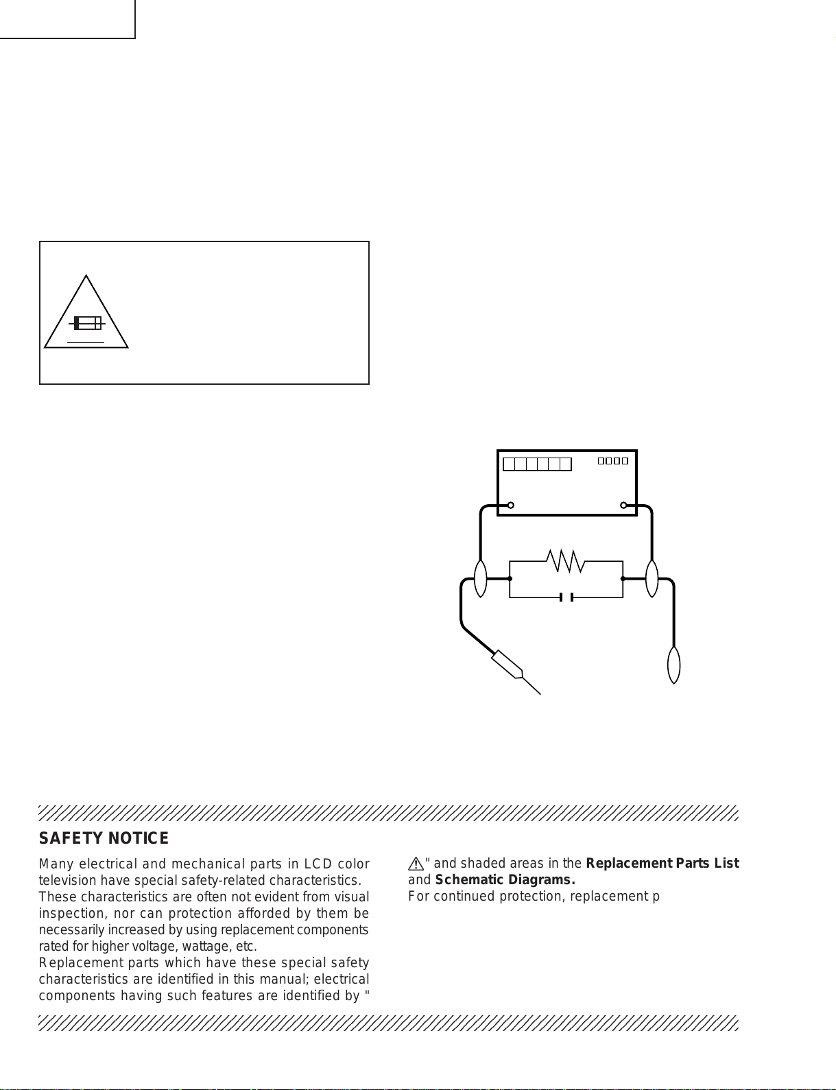
3. To be sure that no shock hazard exists, check for
leakage current in the following manner.
» Plug the AC cord directly into a 120volt AC outlet.
» Using two clip leads, connect a 1.5k ohm, 10 watt
resistor paralleled by a 0.15µF capacitor in series
with all exposed metal cabinet parts and a known
earth ground, such as electrical conduit or electrical
ground connected to an earth ground.
» Use an AC voltmeter having with 5000 ohm per volt,
or higher, sensitivity or measure the AC voltage drop
across the resistor.
» Connect the resistor connection to all exposed metal
parts having a return to the chassis (antenna, metal
cabinet, screw heads, knobs and control shafts,
escutcheon, etc.) and measure the AC voltage drop
across the resistor.
All checks must be repeated with the AC cord plug
connection reversed. (If necessary, a nonpolarized
adaptor plug must be used only for the purpose of
completing these checks.)
Any reading of 0.75 Vrms (this corresponds to 0.5
mA rms AC.) or more is excessive and indicates a
potential shock hazard which must be corrected
before returning the monitor to the owner.
DVM
AC SCALE
1.5k ohm
10W
0.15 µF
TEST PROBE
TO EXPOSED
METAL PARTS
CONNECT TO
KNOWN EARTH
GROUND
23456789012345678901234567890121234567890123456789012345678901212345678901234567890123456789012
SAFETY NOTICE
Many electrical and mechanical parts in LCD color
television have special safety-related characteristics.
These characteristics are often not evident from visual
inspection, nor can protection afforded by them be
necessarily increased by using replacement components
rated for higher voltage, wattage, etc.
Replacement parts which have these special safety
characteristics are identified in this manual; electrical
components having such features are identified by "
23456789012345678901234567890121234567890123456789012345678901212345678901234567890123456789012
å" and shaded areas in the Replacement Parts List
and Schematic Diagrams.
For continued protection, replacement parts must be
identical to those used in the original circuit.
The use of a substitute replacement parts which do not
have the same safety characteristics as the factory
recommended replacement parts shown in this service
manual, may create shock, fire or other hazards.
2
Page 3
LC-26GA4D
2
2
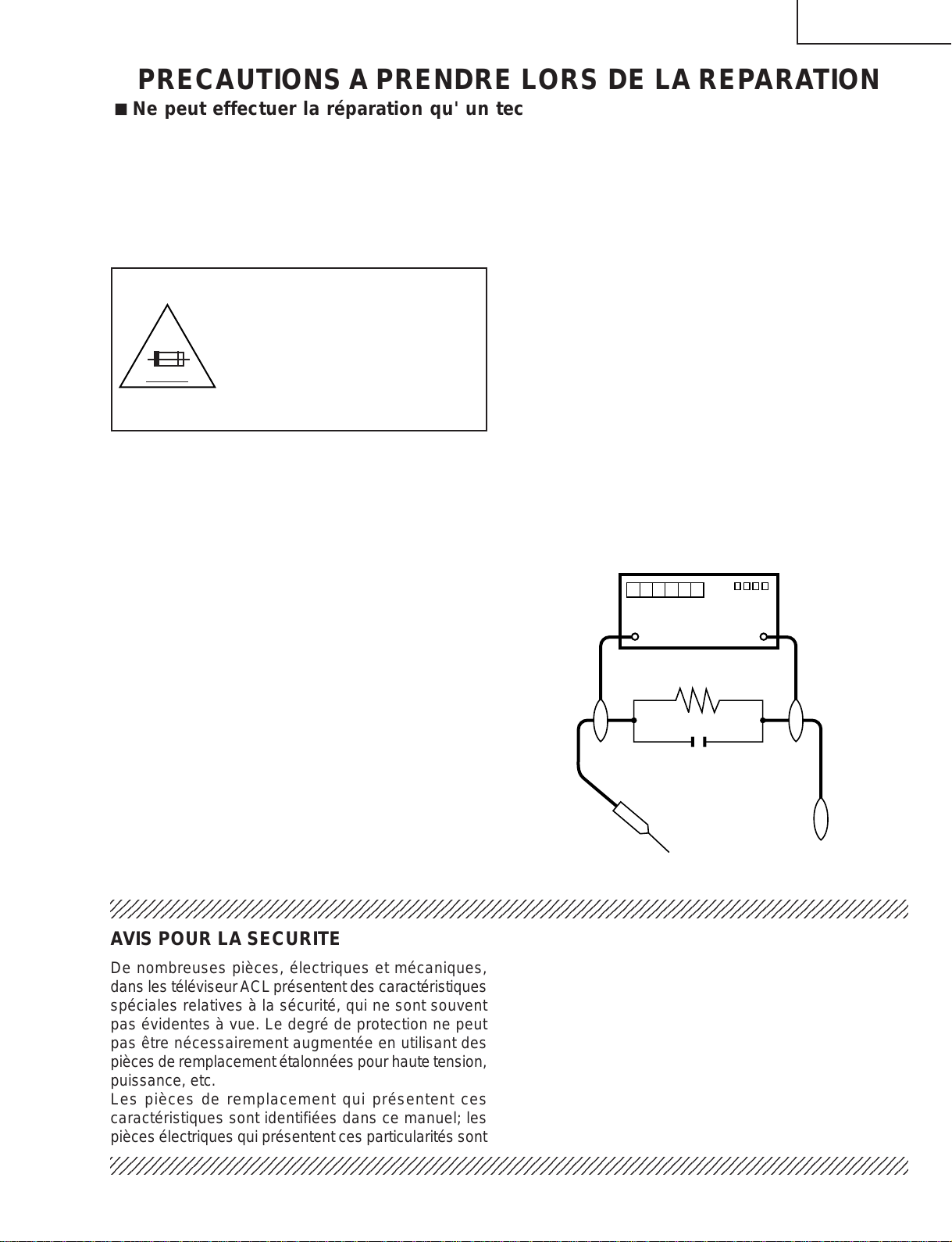
DVM
ECHELLE CA
1.5k ohm
10W
0.15 µF
SONDE D'ESSAI
AUX PIECES
METALLIQUES
EXPOSEES
BRANCHER A UNE
TERRE CONNUE
LC-26GA4U
PRECAUTIONS A PRENDRE LORS DE LA REPARATION
Ë
Ne peut effectuer la réparation qu' un technicien spécialisé qui s'est parfaitement
accoutumé à toute vérification de sécurité et aux conseils suivants.
AVERTISSEMENT
1. N'entreprendre aucune modification de tout circuit.
C'est dangereux.
2. Débrancher le récepteur avant toute réparation.
PRECAUTION: POUR LA
PROTECTION CONTINUE CONTRE
LES RISQUES D'INCENDIE,
REMPLACER LE FUSIBLE
F701 (3.15A, 250V), F702 (3.15A,
A V
250V), F703 (2A, 250V), F705 (1A,
DC450V), F706 (5A, 250V), F707 (5A,
250V)
VERIFICATIONS CONTRE L'INCEN-DIE ET
LE CHOC ELECTRIQUE
Avant de rendre le récepteur à l'utilisateur, effectuer
les vérifications suivantes.
1. Inspecter tous les faisceaux de câbles pour s'assurer
que les fils ne soient pas pincés ou qu'un outil ne soit
pas placé entre le châssis et les autres pièces
métalliques du récepteur.
2. Inspecter tous les dispositifs de protection comme les
boutons de commande non-métalliques, les isolants,
le dos du coffret, les couvercles ou blindages de réglage
et de compartiment, les réseaux de résistancecapacité, les isolateurs mécaniques, etc.
3. S'assurer qu'il n'y ait pas de danger d'électrocution en
vérifiant la fuite de courant, de la facon suivante:
• Brancher le cordon d'alimentation directem-ent à une
prise de courant de 120V. (Ne pas utiliser de
transformateur d'isolation pour cet essai).
• A l'aide de deux fils à pinces, brancher une résistance
de 1.5 kΩ 10 watts en parallèle avec un condensateur
de 0.15µF en série avec toutes les pièces métalliques
exposées du coffret et une terre connue comme une
conduite électrique ou une prise de terre branchée à
la terre.
• Utiliser un voltmètre CA d'une sensibilité d'au moins
5000Ω/V pour mesurer la chute de tension en travers
de la résistance.
• Toucher avec la sonde d'essai les pièces métalliques
exposées qui présentent une voie de retour au châssis
(antenne, coffret métallique, tête des vis, arbres de
commande et des boutons, écusson, etc.) et mesurer
la chute de tension CA en-travers de la résistance.
T outes les vérifications doivent être refaites après avoir
inversé la fiche du cordon d'alimentation. (Si
nécessaire, une prise d'adpatation non polarisée peut
être utilisée dans le but de terminer ces vérifications.)
Tous les courants mesurés ne doivent pas dépasser
0.5 mA.
Dans le cas contraire, il y a une possibilité de choc
électrique qui doit être supprimée avant de rendre le
récepteur au client.
234567890123456789012345678901212345678901234567890123456789012123456789012345678901234567890121
AVIS POUR LA SECURITE
De nombreuses pièces, électriques et mécaniques,
dans les téléviseur ACL présentent des caractéristiques
spéciales relatives à la sécurité, qui ne sont souvent
pas évidentes à vue. Le degré de protection ne peut
pas être nécessairement augmentée en utilisant des
pièces de remplacement étalonnées pour haute tension,
puissance, etc.
Les pièces de remplacement qui présentent ces
caractéristiques sont identifiées dans ce manuel; les
pièces électriques qui présentent ces particularités sont
234567890123456789012345678901212345678901234567890123456789012123456789012345678901234567890121
identifiées par la marque " å " et hachurées dans la
liste des pièces de remplacement et les diagrammes
schématiques.
Pour assurer la protection, ces pièces doivent être
identiques à celles utilisées dans le circuit d'origine.
L'utilisation de pièces qui n'ont pas les mêmes
caractéristiques que les pièces recommandées par
l'usine, indiquées dans ce manuel, peut provoquer des
électrocutions, incendies, radiations X ou autres
accidents.
3
Page 4
LC-26GA4D
LC-26GA4U
Precautions for using lead-free solder
1 Employing lead-free solder
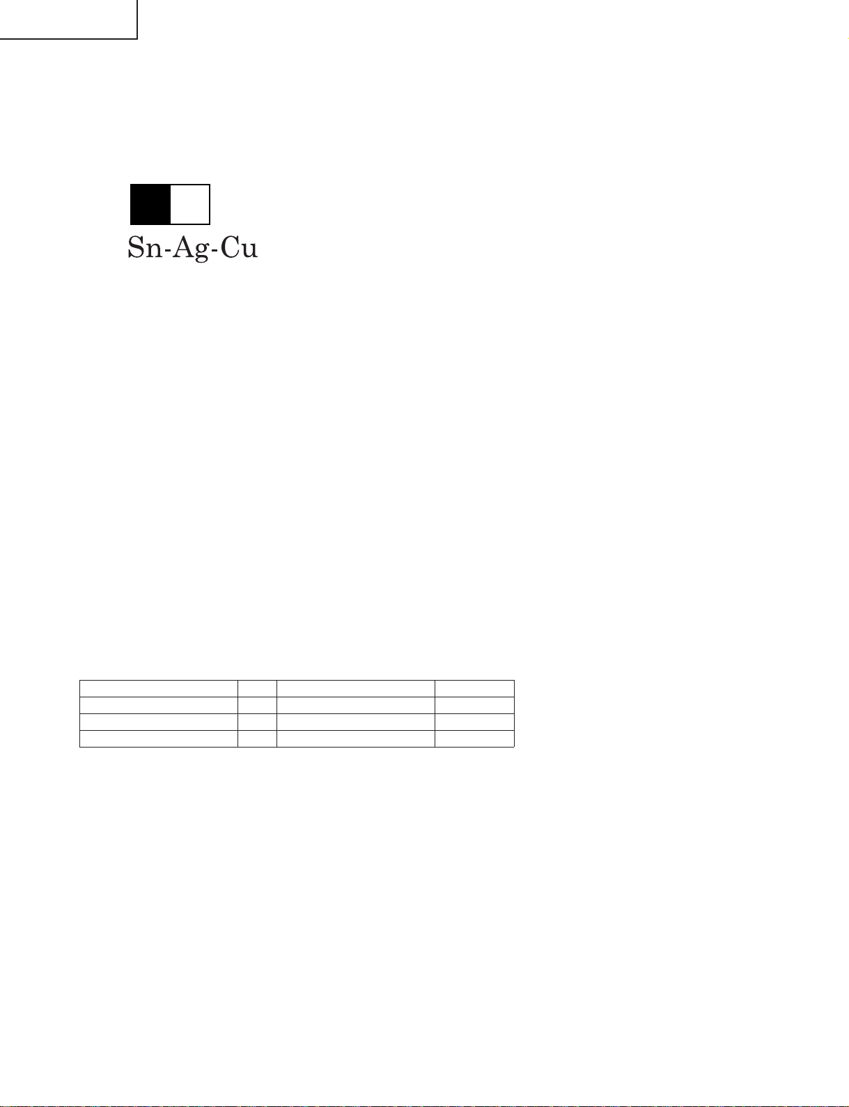
"PWBs" of this model employs lead-free solder. The LF symbol indicates lead-free solder, and is attached on the
PWBs and service manuals. The alphabetical character following LF shows the type of lead-free solder.
Example:
L Fa
Indicates lead-free solder of tin, silver and copper.
2 Using lead-free wire solder
When fixing the PWB soldered with the lead-free solder, apply lead-free wire solder. Repairing with conventional
lead wire solder may cause damage or accident due to cracks.
As the melting point of lead-free solder (Sn-Ag-Cu) is higher than the lead wire solder by 40°C, we recommend
you to use a dedicated soldering bit, if you are not familiar with how to obtain lead-free wire solder or soldering bit,
contact our service station or service branch in your area.
3 Soldering
As the melting point of lead-free solder (Sn-Ag-Cu) is about 220°C which is higher than the conventional lead
solder by 40°C, and as it has poor solder wettability, you may be apt to keep the soldering bit in contact with the
PWB for extended period of time. However, Since the land may be peeled off or the maximum heat-resistance
temperature of parts may be exceeded, remove the bit from the PWB as soon as you confirm the steady soldering
condition.
Lead-free solder contains more tin, and the end of the soldering bit may be easily corroded. Make sure to turn on
and off the power of the bit as required.
If a different type of solder stays on the tip of the soldering bit, it is alloyed with lead-free solder . Clean the bit after
every use of it.
When the tip of the soldering bit is blackened during use, file it with steel wool or fine sandpaper.
Be careful when replacing parts with polarity indication on the PWB silk.
Lead-free wire solder for servicing
Part No, ★ Description Code
ZHNDAi123250E J φ0.3mm 250g(1roll) BL
ZHNDAi126500E J φ0.6mm 500g(1roll) BK
ZHNDAi12801KE J φ1.0mm 1kg(1roll) BM
4
Page 5
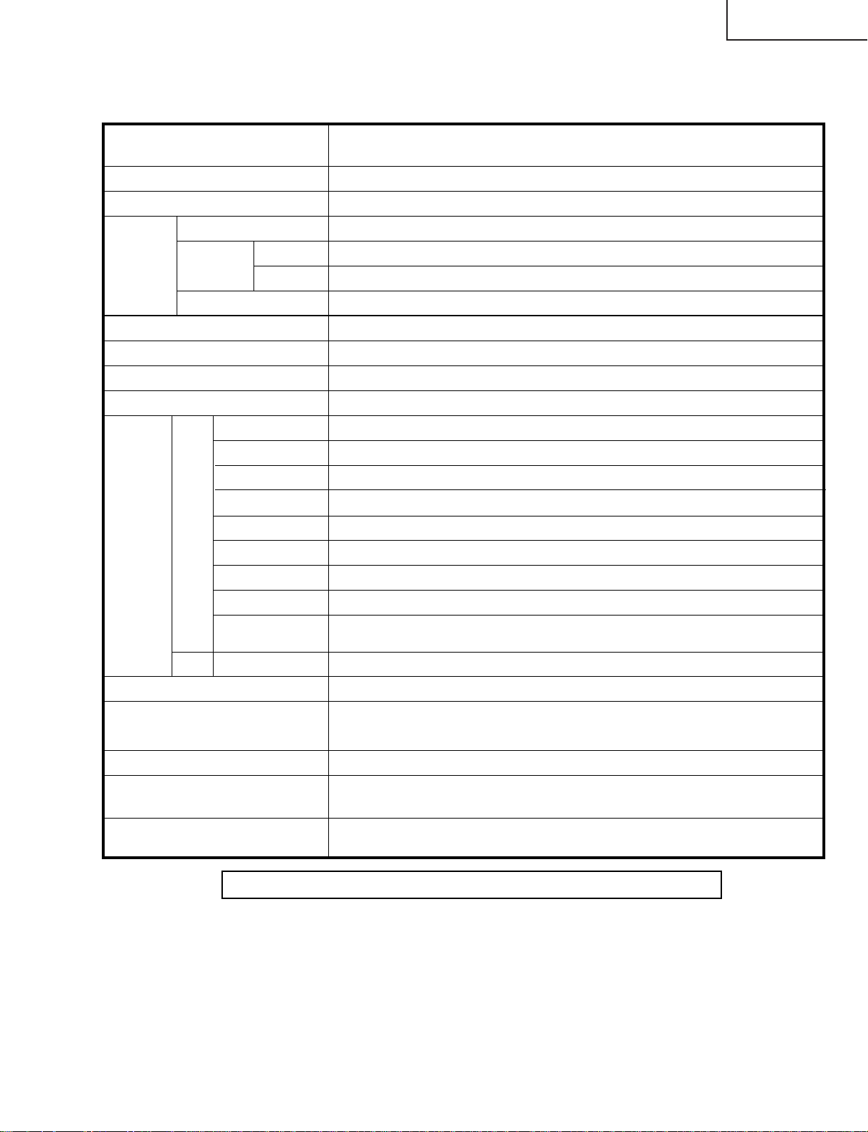
SPECIFICATIONS
Item 26" LIQUID CRYSTAL TELEVISION,
Model: LC-26GA4U
LCD panel 26" Advanced Super View & BLACK TFT LCD
LC-26GA4D
LC-26GA4U
Number of dots 3,147,264 dots (1366 768 3 dots)
TV
Function
Brightness 450 cd/m
Viewing angles H : 170° V : 170°
Audio amplifier 10W 2
Speakers Ø 8cm 2pcs, Ø 2.5cm 2pcs
Terminals AV in, COMPONENT in
TV-standard (CCIR)
Receiving
Channel
Audio multiplex BTSC System
Rear INPUT 1
INPUT 2
INPUT 4
INPUT 5 Audio in, DVI-I in
ANTENNA 75 Unbalance, F Type for VHF/UHF/CATV in 2, out 1
MONITOR OUTPUT
CENTER
CHANNEL INPUT
VHF/UHF
CATV 1-125ch
INPUT 3
American TV Standard NTSC System
VHF 2-13ch, UHF 14-69ch
2
×
AV in, COMPONENT in
S-VIDEO in, AV in
HDMI in
Ω
S-VIDEO out, AV out
Ω
4 10W (L/R)SPEAKER
RCA pin
××
××
Front
OSD language
Power Requirement
Power Consumption
Weight
Accessories Operation manual ( 1), Remote control unit ( 1), AC cord ( 1), "AAA" size
Headphones Ø 3.5mm jack
English/French/Spanish
AC 120 V, 60 Hz (FOR NORTH AMERICA)
AC 110-240 V, 50/60 Hz(FOR OTHERS)
139W (0.4W Standby with AC 120 V)
26.5 lbs./12 kg (Display only), 34.2 lbs./15.5 kg (with Display and speaker),
40.8 lbs./18.5 kg (with Display, speaker and stand)
battery ( 2), RF cable ( 1)
××
×××
Specifications are subject to change without prior notice.
5
Page 6
LC-26GA4D
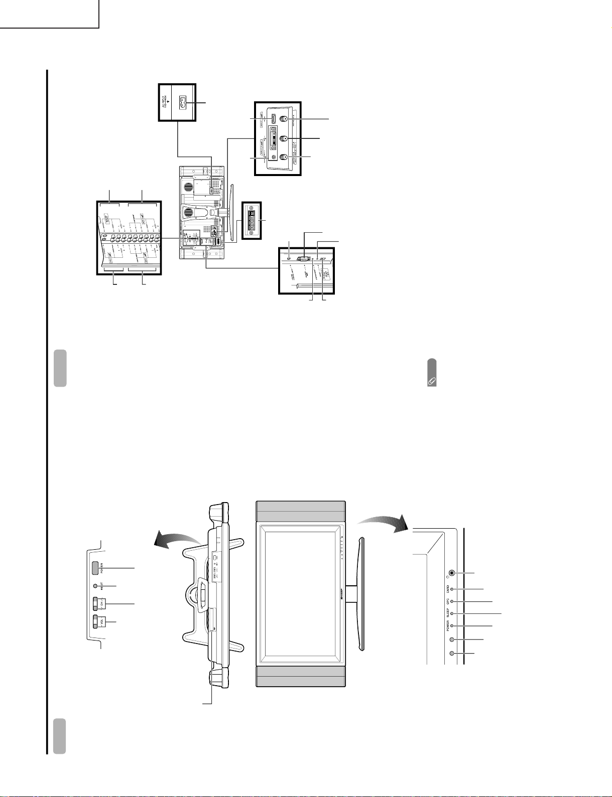
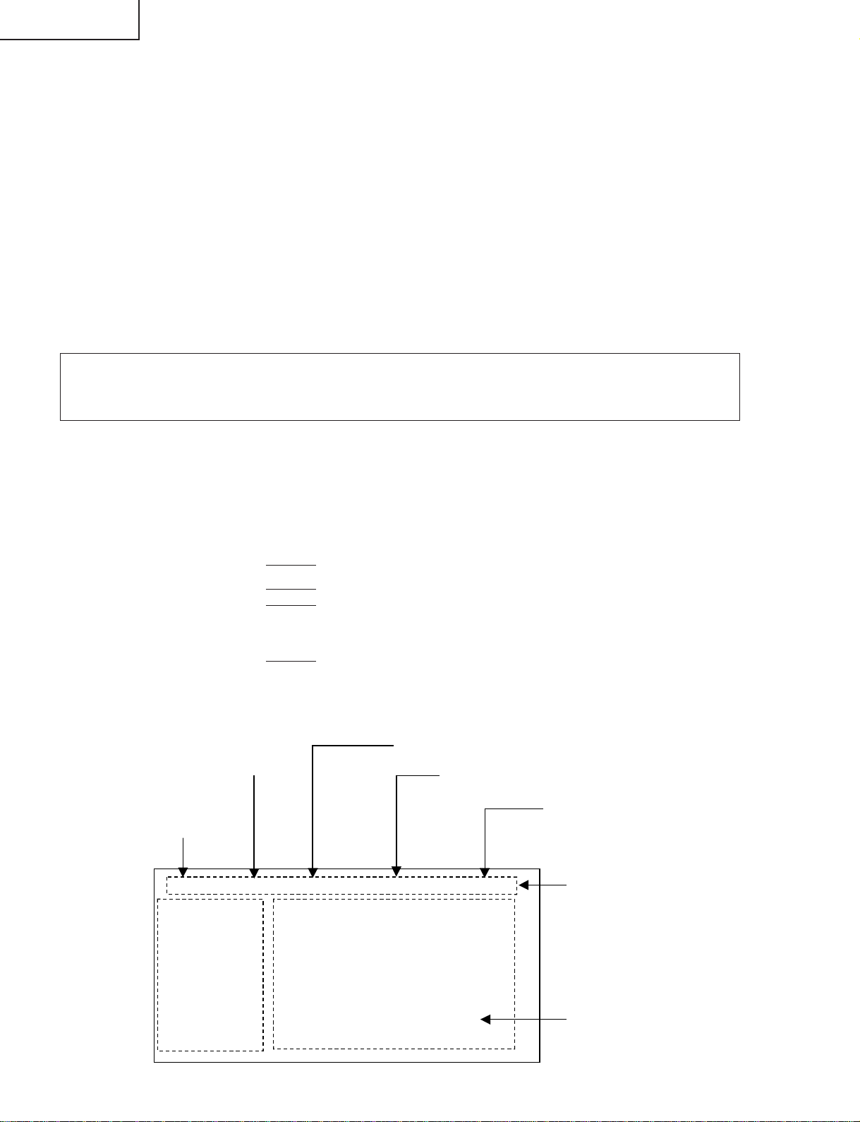
Part names
POWER indicator
OPC sensor
Display
POWER (On/Off)
button
INPUT
button
VOLUME buttons
(VOL-/+)
CHANNEL buttons
(CH )
Remote control sensor
*OPC: Optical Picture Control
SLEEP timer indicator
OPC indicator
Headphone jack
CARD indicator
PC CARD slot
Ù/ù
RESET*
INPUT 3 terminals
SYSTEM RESET**
Display
Antenna (A) input terminal
Antenna (B) input terminal
Antenna (A) output terminal
* Press RESET if the TV cannot return to its original state after performing various operations.
• AV MODE resets to DYNAMIC (Fixed)
• TV channel returns to initial channel setting (Air:2ch, Cable:1 or 2ch)
• Twin pictur
e resets to normal
• Audio setting initializes
• Dolby virtual resets to Off
• Image position initializes
**Press SYSTEM RESET if the TV does not operate after starting up.
NOTE
• Pressing RESET will not work if the TV is in standby mode (indicator lights red).
• Pressing RESET will not delete channel preset or secret number. See page for clearing the secret number when you
know it. See page for initializing to the factory pr eset values when you forget your secret number.
DC OUTPUT
terminal
(Terminal for expanded
functionality in the near future.)
SPEAKER terminals
AC INPUT
terminal
RS-232C
terminal
INPUT 2 terminals
INPUT 1 terminals
INPUT 5 terminals
INPUT 4 terminal
CENTER CHANNEL
INPUT ter
minal
MONITOR OUTPUT terminals
LC-26GA4U
OPERATION MANUAL
6
Page 7
LC-26GA4D
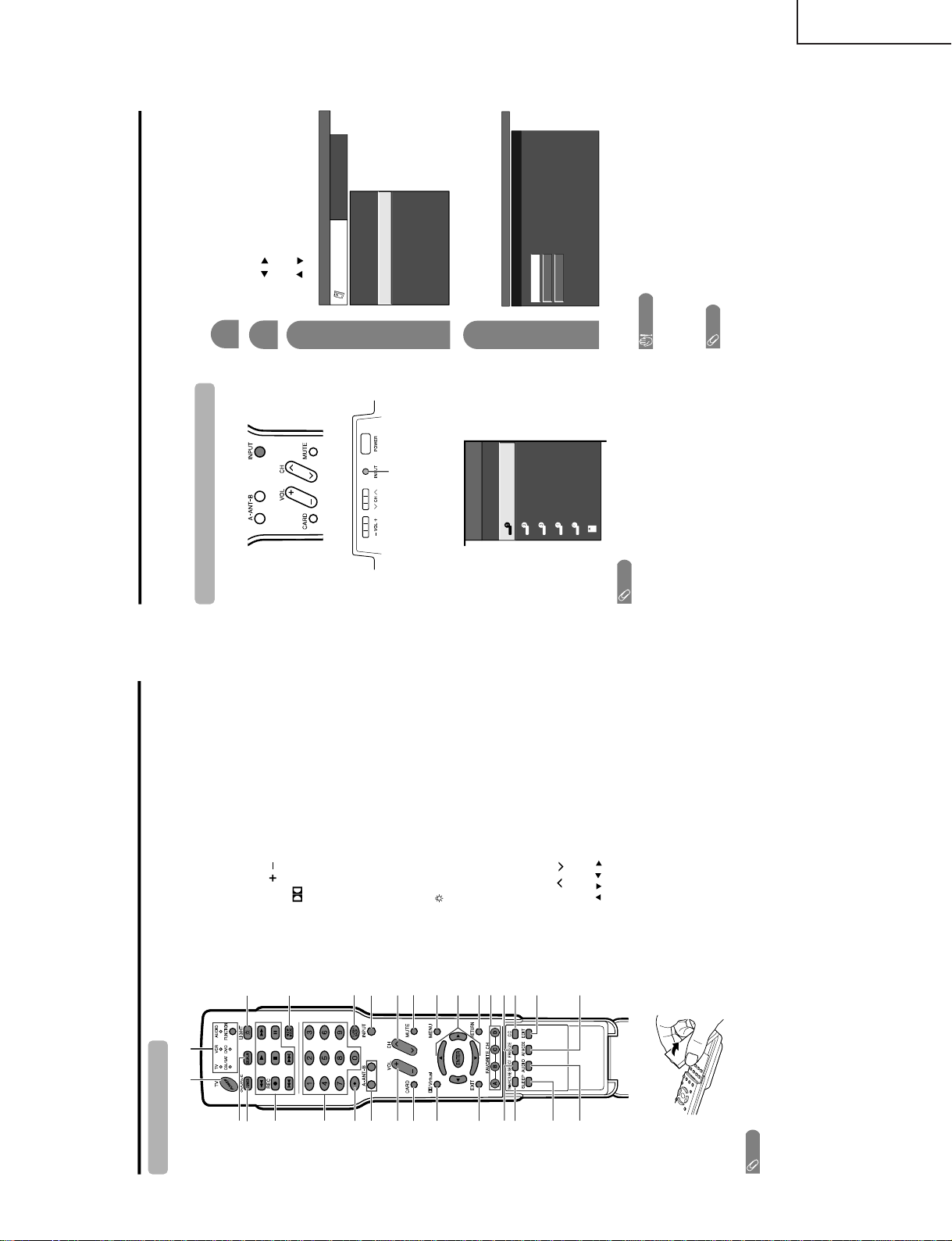
Remote control unit
NOTE
• When using the remote control unit, point it at the TV.
3
2
115
5
6
4
7
18
16
17
19
20
8
9
30
21
22
10 24
25
26
12
11
27
13
14 29
23
28
1 TV POWER: Switch the TV power on or standby.
2 DISPLAY: Display the channel information.
3 SOURCE POWER: Turns the power of the external
equipment on and off.
4 External equipment operational buttons: Operate the
external equipment.
50 – 9: Set the channel.
6 ANT-A/B: Select between ANT-A and B to watch
broadcasts via the two tuners.
7VOL/ : Set the volume.
8 CARD: Switch to card mode.
9
Virtual: Select Virtual Dolby Surround settings.
10 EXIT: Turn off the menu screen.
11 SELECT: Select the active screen.
12 TWIN PICTURE: Set the twin picture mode.
Press again to return to normal screen.
13 SLEEP: Set the sleep timer
.
14 AUDIO: Select the MTS/SAP.
15 FUNCTION: Switches the remote control for TV, CBL/
SAT, VCR, DVD and AUDIO operation. Indicator lights
up for the current mode.
16
: When pressed all buttons on the r emote control unit
will light. The lighting will turn off if no operations are
performed within about 5 seconds. This button is used
for performing operations in dark places.
17 VIEW MODE: Select the screen size.
18 FLASHBACK: Return to the previous channel or input
external mode.
19 INPUT: Select a TV input sour
ce. (TV, INPUT 1, INPUT
2, INPUT 3, INPUT 4, INPUT 5, Card)
20 CH / : Select the channel.
21 MUTE: Mute the sound.
22 MENU: Display the menu screen.
23 ////ENTER: Select a desir ed item on the screen.
24 RETURN: Return to the previous menu screen.
25 FAVORITE CH
A, B, C, D: Select four preset favorite channels in four
different categories.
While watching, you can toggle the selected channels
by pressing A, B, C and D.
26 FREEZE: Set the still image. Press again to return to
normal screen.
27 CC: Display captions during closed-caption source.
28
EDIT:
Register favorite channel.
29 AV MODE: Select an audio or video setting.
USER, DYNAMIC (Fixed), DYNAMIC. PC mode:
STANDARD, USER.)
30
•
(DOT)
(AV mode: STANDARD, MOVIE, GAME,
Part names
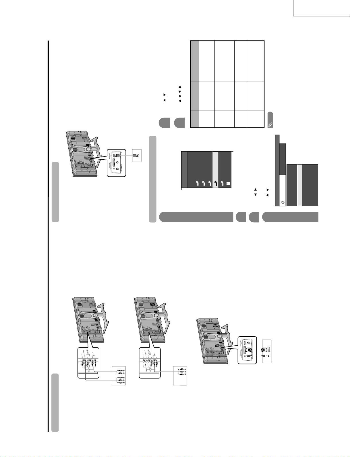
Using external equipment
You can connect many types of external equipment to your TV, like a DVD player, VCR, Digital TV tuner, PC,
HDMI equipment, game console and camcorder. To view external source images, select the input source from
INPUT on the remote control unit or on the Display.
CAUTION
• To protect all equipment, always turn off the TV before
connecting
to a DVD player, VCR, Digital TV tuner, PC,
HDMI equipment, game console, camcorder or other
external equipment.
NOTE
•
• Please
refer to the relevant operation manual (DVD player ,
PC, etc.) car
efully before making connections.
• Each time INPUT is pressed, the input source toggles.
• Refer
to your external equipment operation manual for
the signal type.
Displaying an external equipment image
Explanation here is for the setting when connecting
DVD to INPUT1 terminal.
INPUT button
T o watch a DVD image, select "INPUT1" from "INPUT
SOURCE" menu using INPUT on the remote control
unit or on the Display.
INPUT SOURCE
TV
INPUT1
INPUT2
INPUT3
INPUT4
INPUT5
CARD
1
MENU
[
Option
...
Input Select
]
Auto
COMPONENT
Video
For INPUT1 signal
Select the desired signal type.
The setting is stored and can be selected on the
"INPUT SOURCE" menu.
Press MENU and the MENU scr een displays.
2
3
Press / to select "Input Select", and then
press ENTER.
4
Press / to select "Option".
MENU
[
Option
...
Input Select
]
Option
Input Select
Digital Noise Reduction
Output Select
Audio Only
Quick Shoot
[Fixed]
[Auto]
[Low]
[Off]
Center Channel Input
Caption Setup
[Off]
NOTE
• If the image does not come in clearly, you may need to
change the input signal type setting on the "Input Select"
menu.
Selecting the INPUT signal
See pages for external equipment connection.
LC-26GA4U
7
Page 8
LC-26GA4D
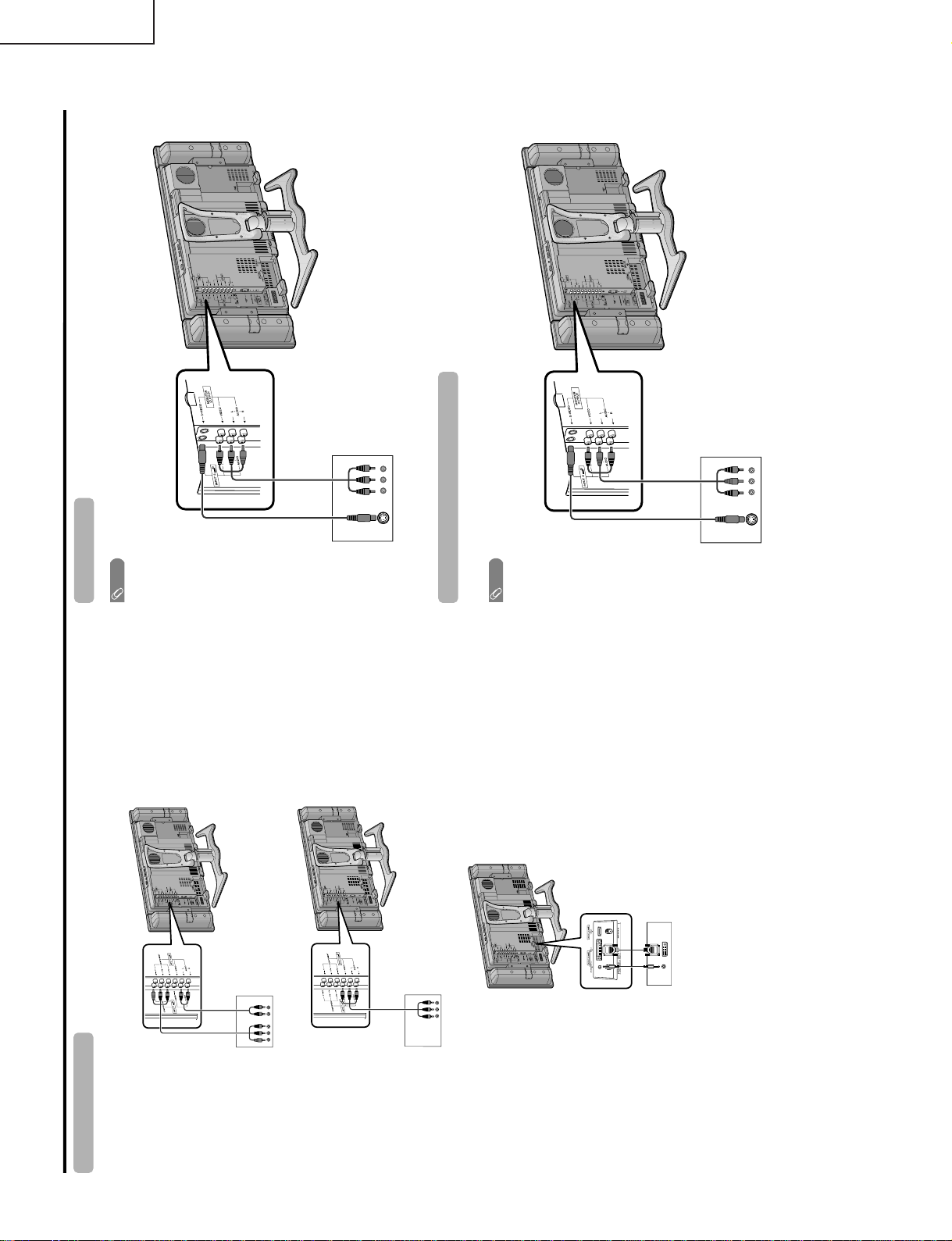
Using external equipment
DVD player
Connecting a DVD player
You can use the INPUT 1, INPUT 2, INPUT 4 or INPUT 5 terminals when connecting to a DVD player and other
audiovisual equipment.
Component
video cable
(commercially
available)
Audio cable
(commercially available)
AV cable (commercially
available)
DVD player
DVD player
ø 3.5 mm stereo minijack cable
(commercially available)
DVI cable (Commercially available)
When using component cable.
When using composite cable.
When using DVI cable. (INPUT 5)
VCR
AV cable
(commercially available)
Connecting a VCR
You can use the INPUT 3 terminal when connecting a VCR and other audiovisual equipment.
Game console/Camcorder
S-video cable
(commercially
available)
Connecting a game console or camcorder
A game console, camcorder and some other audiovisual equipment are conveniently connected using the
INPUT 3 terminals.
NOTE
• The S-video terminal has priority over the video terminals.
AV cable
(commercially available)
S-video cable
(commercially
available)
NOTE
• The S-video terminal has priority over the video terminals.
LC-26GA4U
8
Page 9
Using external equipment
Digital TV STB
Connecting a Digital TV STB
You can use the INPUT 1, INPUT 2, INPUT 4 or INPUT 5 terminals when connecting a Digital TV STB and other
audiovisual equipment.
Component video cable
(commercially available)
Audio cable
(commercially available)
AV cable
(commercially available)
Digital TV STB
Digital TV STB
ø 3.5 mm stereo minijack cable
(commercially available)
DVI cable (Commercially available)
When using component cable.
When using composite cable.
When using D
VI cable. (INPUT 5)
Connecting HDMI equipment
You can use the INPUT 4 terminal when connecting an HDMI equipment.
HDMI equipment
HDMI cable
(Commercially available)
Displaying an image from HDMI equipment
To watch an HDMI equipment image, select
"INPUT4" from "INPUT SOURCE" menu
using INPUT on the remote control unit or
on the TV.
INPUT SOURCE
TV
INPUT1
INPUT2
INPUT3
INPUT4
INPUT5INPUT5
CARD
1
Press MENU and the MENU scr een displays.
2
3
Press / to select "HDMI Setup", and then
press ENTER.
4
Press / to select "Option".
MENU
[
Option
...
HDMI Setup
]
Option
Digital Noise Reduction
Output Select
Center Channel Input
Audio Only
Quick Shoot
[Fixed]
[Off]
HDMI Setup
[Low]
[Off]
5
Press / to select the desired item and
press ENTER.
Press / / / to
select the desired setting
and press ENTER.
6
NOTE
• Refer to your external equipment operation manual for
the signal type.
Selectable items
Auto/RGB/YCbCr
4:4:4/YCbCr 4:2:2
Auto/ITU601/
ITU709
Standard/
Out of standard
Enable/Disable
HDMI Setup
items
Signal
Type
Color
Matrix
Dynamic
Range
Auto View
Description
Select the signal type from
an HDMI terminal. Unless
the image quality looks
obviously poor, select Auto.
Select the internal color
space conversion method
when an RGB signal is
input. Normally, select
Auto.
Select the signal amplitude
range. Normally, select
Standard.
Set whether or not to use
VIEW MODE based on
signal recognition,
including an HDMI signal.
LC-26GA4D
LC-26GA4U
9
Page 10
LC-26GA4D
Using external equipment
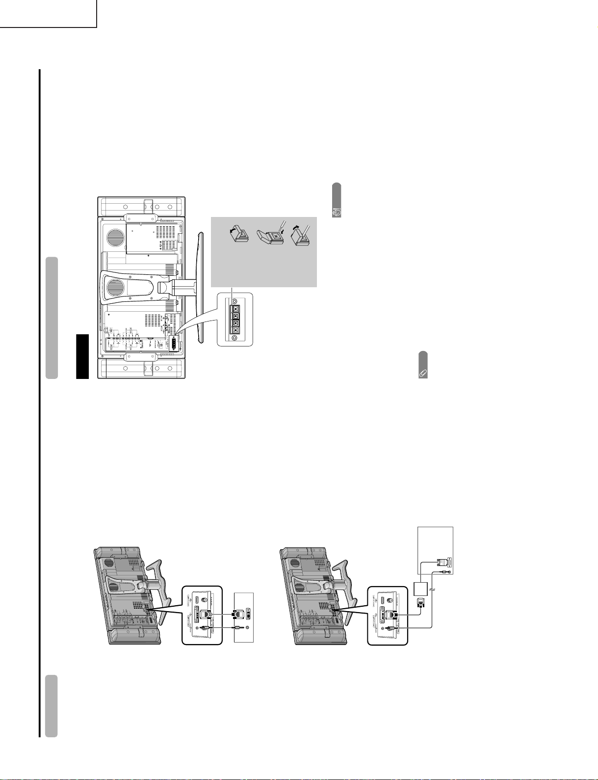
PC with DVI terminal
Connecting a PC
Use the INPUT 5 terminal to connect a PC.
ø 3.5 mm stereo minijack cable
(commercially available)
DVI cable (Commercially available)
ø 3.5 mm stereo minijack cable
(commercially available)
PC with analog RGB terminal
RGB/DVI conversion cable
(Commercially available)
Rear view
Connecting external speakers
Make sure to connect the speaker terminal and
cable polarity ( , ) properly
• The speaker terminals have plus ( ) and minus ( )
polarity.
• Plus is red and minus is black.
• The cables are also divided into plus and minus.
• When connecting the left/right speakers, be sure to
connect the plus/minus terminals with the correct cables.
NOTE
• Unplug the AC cord from the AC outlet before installing
the speakers.
CAUTION
• Make sure external speakers have 4 ohm and 10 watt
specifications.
• Connect the plus/minus terminals with the correct cables.
Incorrect connection may cause a short.
How to connect the
speaker cable
Pull up the
lid.
Insert the
edge of the
cable.
Put the lid
bac
k
down.
Make sure to disconnect the connected speaker
cables in advance when connecting external
speakers.
–
–
+
+
1
2
3
LC-26GA4U
10
Page 11
RS-232C port specifications
Return codeCommand 4-digits Parameter 4-digits
PC Control of the TV
• When a program is set, the TV can be controlled from the PC using the RS-232C terminal. The input signal
(PC/AV) can be selected, the volume can be adjusted and various other adjustments and settings can be
made, enabling automatic programmed playing.
•
Attach an RS-232C cable cross-type (commercially available) to the supplied Din/D-Sub RS-232C for the
connections.
NOTE
• This operation system should be used by a person who is accustomed to using computers.
Communication conditions
Set the RS-232C communications settings on the PC to match the display
’
s communications conditions.
The TV’s communications settings are as follows:
Baud rate:
Parity bit:
Data length:
Stop bit:
Flow control:
9,600 bps
8 bits
None
1 bit
None
Appendix
Command format
Communication procedure
Send the control commands from the PC via the RS-232C connector.
The TV operates according to the received command and sends a response message to the PC.
Do not send multiple commands at the same time. Wait until the PC receives the OK response before sending
the next command.
Eight ASCII codes CR
Command 4-digits:Command. The text of four characters.
Parameter 4-digits:Parameter 0 – 9, x, blank, ?
Parameter
Input the parameter values, aligning left, and fill with blank(s) for the remainder. (Be sure that 4 values are input for the
parameter.)
When the input parameter is not within an adjustable range, "ERR" returns. (Refer to "Response code format".)
No problem to input any numerical value for "x" on the table.
When "?" is input for some commands, the present setting value responds.
C1 C2 C3 C4 P1 P2 P3 P4
0055
100
30
0009
0
????
?
+
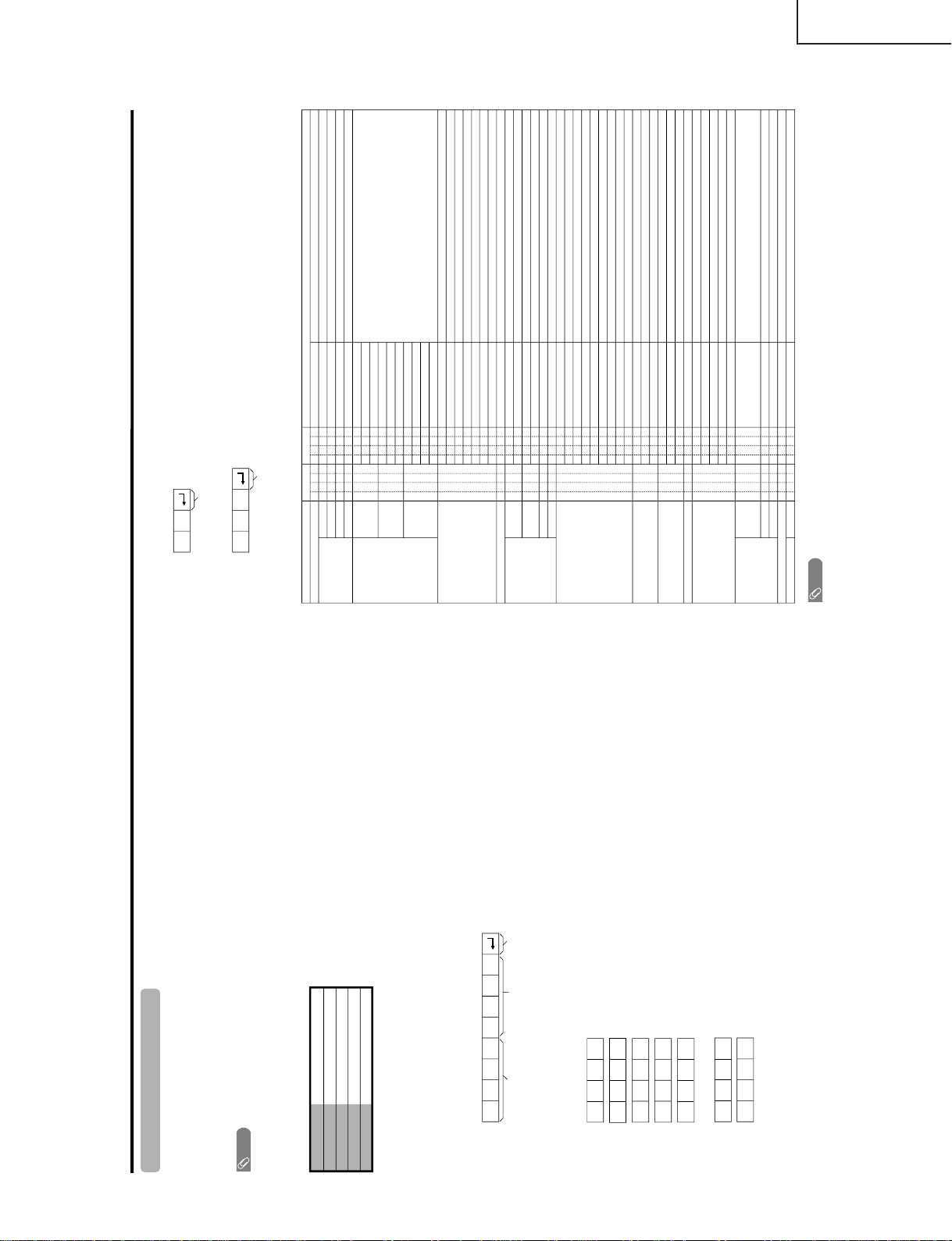
Command table
• About the command except being indicated here, it is outside the guarantee range of operation.
CONTROL ITEM COMMAND
PARAMETER
CONTROL CONTENTS
POWER SETTING It shifts to standby.
It input-switches by the toggle. (It is the same as an input change key)
It input-switches to TV. (A channel remains as it is. (Last memory))
It input-switches to INPUT1~INPUT5.
It shifts to CARD mode.
An input change is also included.
Although it can choose now, it is toggle operation in inside.
Although it can choose now, it is toggle operation in inside.
(Toggle)
Input terminal number (1
–5)
AUTO
VIDEO
COMPONENT
DIGITAL PC
ANALOG PC
DIGITAL AV
ANALOG AV
(Toggle)
STANDARD
MOVIE
USER
GAME
DYNAMIC (Fixed)
DYNAMIC
Volume (0–60)
AV mode. ( 10)
PC mode. (0–180)
AV mode. ( 20)
PC mode. (0–100)
Only PC mode. (0
–180)
Only PC mode. (0
–40)
(Toggle) [AV]
An input change is included if it is not TV display.
In Air, 2–69ch is effective.
In Cable, 1–125ch is effective.
If it is not TV display, it will input-switch to TV.
If it is not TV display, it will input-switch to TV.
Change toggle operation of tuner A/B.
Toggle operation of a closed caption.
(Toggle)
Side Bar [AV]
S.Stretch [AV]
Zoom [AV]
Stretch [AV]
Normal [PC]
Zoom [PC]
Stretch [PC]
Dot by Dot [PC]
On
Off
OFF
OFF TIMER – 30 MIN.
The channel number of TV
The channel number of TV 1
The channel number of TV 1
(Toggle)
(Toggle)
(1–125)
AUTO
POWR
ITGD
ITVD
IAVD
ICRD
INP1
INP5
INPUT SELECTION A TOGGLE
INPUT SELECTION B
AV MODE SELECTION
VOLUME
POSITION
VIEWMODE
Dolby Virtual
SLEEP TIMER
CHANNEL
ANT-A/B
CC
DIRECT
CH UP
CH DOWN
CHANNEL
H-POSITIONH-POSITION
V-POSITION
CLOCK
PHASE
INPUT 1
INPUT 5
AVMD
VOLM
HPOS
VPOS
CLCK
PHSE
ACDV
OFTM
DCCH
CHUP
CHDW
ANTS
CLCP
WIDE
0
x
0
*
x
0
5
6
7
8
1
2
0
*
*
*
*
*
0
0
*
x
x
x
x
1
1
2
0
1
2
3
4
5
6
7
8
*
*
1
2
3
4
5
6
*
_
_
_
_
_
_
_
_
_
_
_
_
_
_
_
_
_
_
*
*
*
*
*
*
*
_
_
_
_
_
_
_
_
_
_
_
_
_
_
_
_
_
_
_
*
_
_
_
_
_
_
_
_
_
_
_
_
_
_
_
_
_
_
*
*
*
*
*
*
_
_
_
_
_
_
_
_
_
_
_
_
_
_
_
_
_
_
_
_
_
_
_
_
_
_
(Toggle)
AUDIO SELECTION
ACHAx _ __
_
_
OFF TIMER – 60 MIN.
OFF TIMER – 90 MIN.
2
3
_
_
_
_
_
_
OFF TIMER – 120 MIN. 4___
_
_
(Toggle)
On
Off
MUTE
MUT E 0
1
2
_
_
_
_
_
_
_
_
_
_
_
_
_
_
_
_
_
_
_
_
_
_
_
_
_
_
_
_
_
_
_
_
_
_
_
_
_
AUTO
VIDEO
COMPONENT
AUTOINP2
INPUT 2
0
1
2
_
_
_
_
_
_
_
_
_
_
_
_
_
_
_
_
TV
INPUT1-5
CARD
NOTE
• If an underbar (_) appears in the parameter column, enter a space.
• If an asterisk (*) appears, enter a value in the range indicated in brackets under CONTROL CONTENTS.
• As long as that from which the parameter ( ) in the table is a numerical value, it may write anything.
Return code (0DH)
Response code format
Normal response
Problem response (communication error or incorrect command)
Return code (0DH)
OK
ERR
×
LC-26GA4D
LC-26GA4U
11
Page 12
LC-26GA4D
Appendix
PC compatibility chart
Apple and Macintosh are registered trademarks
of Apple Computer, Inc.
DDC is a registered trademark of Video Electronics
Standards Association.
Power Management is a registered trademark of
Sun Microsystems, Inc.
VGA and XGA are registered trademarks of
International Business Machines Co., Inc.
PC/MAC Resolution
Horizontal Frequency
Vertical Frequency
VESA Standard
PC
31.5 kHz
37.9 kHz
31.5 kHz
37.9 kHz
31.5 kHz
37.9 kHz
37.5 kHz
43.3 kHz
31.5 kHz
35.1 kHz
37.9 kHz
48.1 kHz
46.9 kHz
53.7 kHz
48.4 kHz
56.5 kHz
60.0 kHz
68.7 kHz
45.0 kHz
48.1 kHz
64.0 kHz
34.9 kHz
49.7 kHz
60.2 kHz
640 x 400
720 x 400
VGA
640 x 480
WVGA 848 x 480
SVGA
800 x 600
1024 x 768XGA
1280 x 720
WXGA
1280 x 768
SXGA
1280 x 1024
VGA
640 x 480
MAC13"
XGA
1024 x 768
MAC19"
SVGA
832 x 624
MAC16"
60 Hz
85 Hz
60 Hz
85 Hz
60 Hz
72 Hz
75 Hz
85 Hz
60 Hz
56 Hz
60 Hz
72 Hz
75 Hz
85 Hz
60 Hz
70 Hz
75 Hz
85 Hz
60 Hz
60 Hz
60 Hz
67 Hz
75 Hz
75 Hz
O
O
O
O
O
O
O
O
O
O
O
O
O
O
O
O
Basic adjustment settings
AV input mode menu items
List of AV menu items to help you with
operations
OPC
Backlight
Contrast
Brightness
Color
Tint
Sharpness
Advanced
C.M.S.
Color Temp.
Black
3D-Y/C
Monochrome
Film Mode
I/P Setting
Picture
No Signal Off
No Operation Off
EZ Setup
CH Setup
Speaker Setup
Input Label
Parental CTRL
Position
Picture Flip
Langua
ge
Treble
Bass
Balance
Dolb
y Virtual
Audio Only
Digital Noise Reduction
HDMI Setup
Input Select
Output Select
Quick Shoot
Center Channel Input
Caption Setup
Audio
Power Control
Setup
Option
PC input mode menu items
List of PC menu items to help you with
operations
OPC
Backlight
Contrast
Brightness
Red
Green
Blue
Advanced
C.M.S.
Picture
Power Management
Speaker Setup
Input Signal
Auto Sync.
Input Label
Fine Sync.
Picture Flip
Language
Audio
Power Control
Setup
Treble
Bass
Balance
Dolby Virtual
Option
Audio Only
Input Select
Output Select
Quic
k Shoot
Center Channel Input
LC-26GA4U
12
Page 13
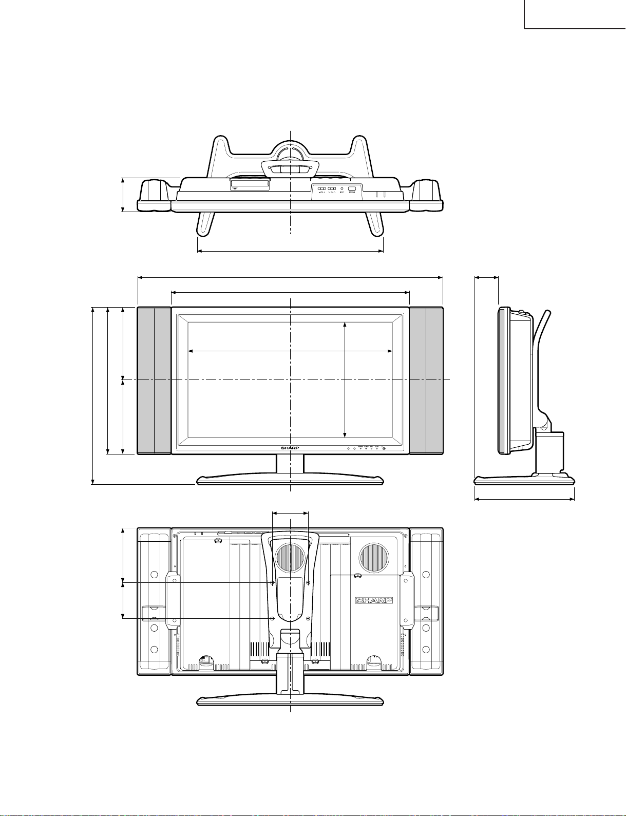
Unit: inch/(mm)
315/16 (100)
3
15
/
16
(100) 5
15
/
16
(151)
2223/64 (568)
12
5
/
8
(321)
267/64 (663)
333/8 (848)
8
7
/
64
(206)
19
13
/
32
(493)
7
29
/
32
(201)
16
1
/
64
(407)
3
47
/
64
(95)
2023/64 (517)
243/64 (68)
1015/16 (278)
LC-26GA4D
LC-26GA4U
DIMENSIONS
13
Page 14
LC-26GA4D
LC-26GA4U
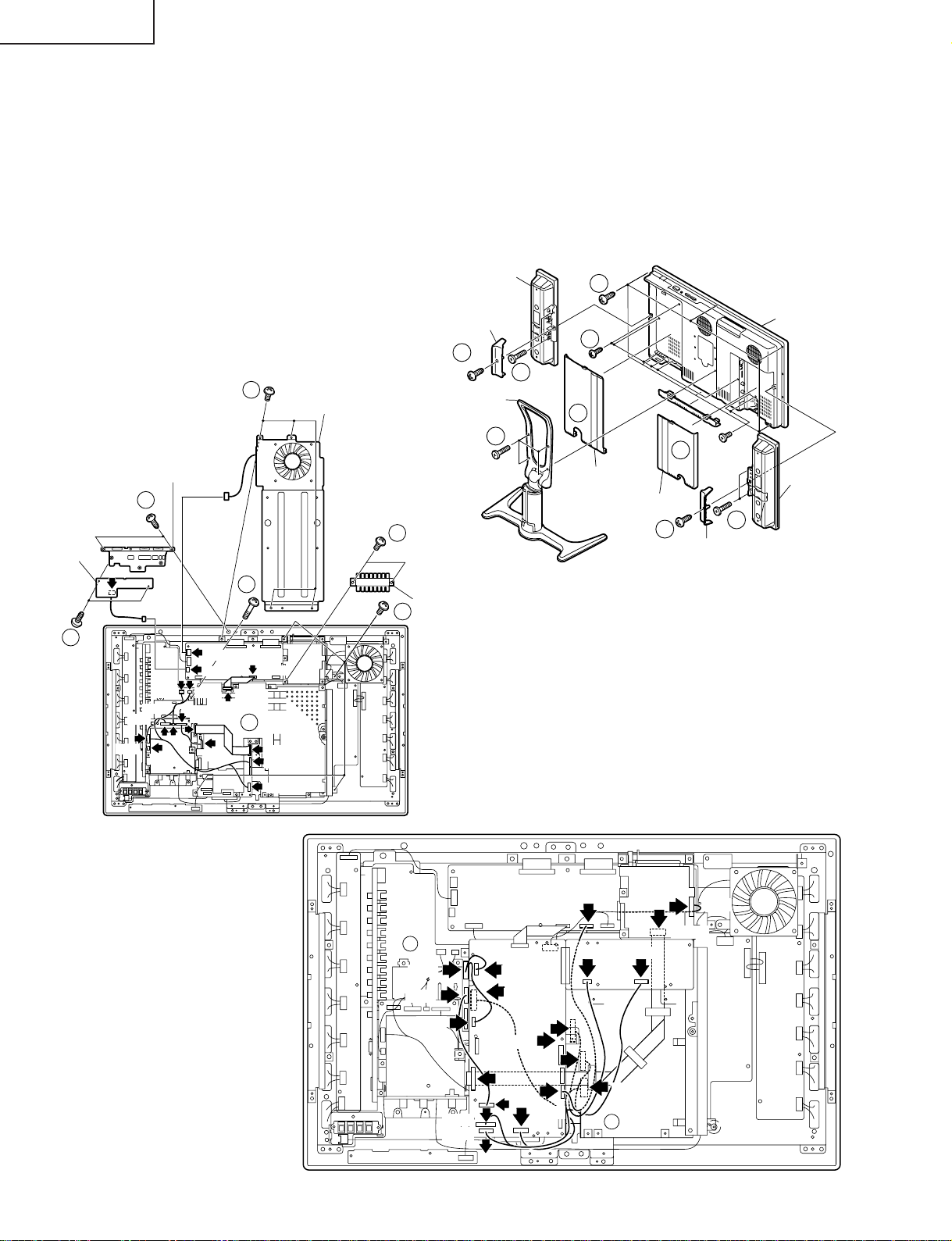
REMOVING OF MAJOR PARTS
1. Remove the four lock screws from the stand, and detach the stand.
2. Remove the terminal cover(left, right and bottom).
3. Remove the two lock screws each from the bracket cover(left and right), and detach both the bracket covers.
4. Remove the two lock screws each from the speaker(left and right), and detach both the speakers.
5. Remove the 15 lock screws from the cabinet-B, and detach the cabinet-B.
6. Remove the four lock screws from the center angle, and detach the center angle.
7. Remove the key PWB.
7-1. Remove the two lock screws from the top cover.
7-2. Remove the two lock screws from the key PWB.
8. Remove the two lock screws from the angle.
9. Remove the five screws from main PWB frame.
10. Disconnect all the connectors from all the PWBs.
6
Center Angle
Top Cover
7-1
8
KEY PWB
Speaker
Bracket Cover
3
Stand
1
4
Terminal Cover (R)
5
5
2
Terminal Cover (L)
2
3
Bracket Cover
Cabinet-A
4
Speaker
7-2
P151
P1900
P1901
P1904
P1902
P5706
P1903
SC3802
P2002
P7706
P5702
P3701
SC3200
9
10
SC4601
SC7200
P7200
P3700
9
10
P5701
P3802
Angle
P1502
P1803
P1804
P1802
P3803
P3801
SC7201
P401
P501
P5704
CN708
P1501
P2006
P8506
P5002
SC5102
P8502
CN706
10
14
Page 15
LC-26GA4D
LC-26GA4U
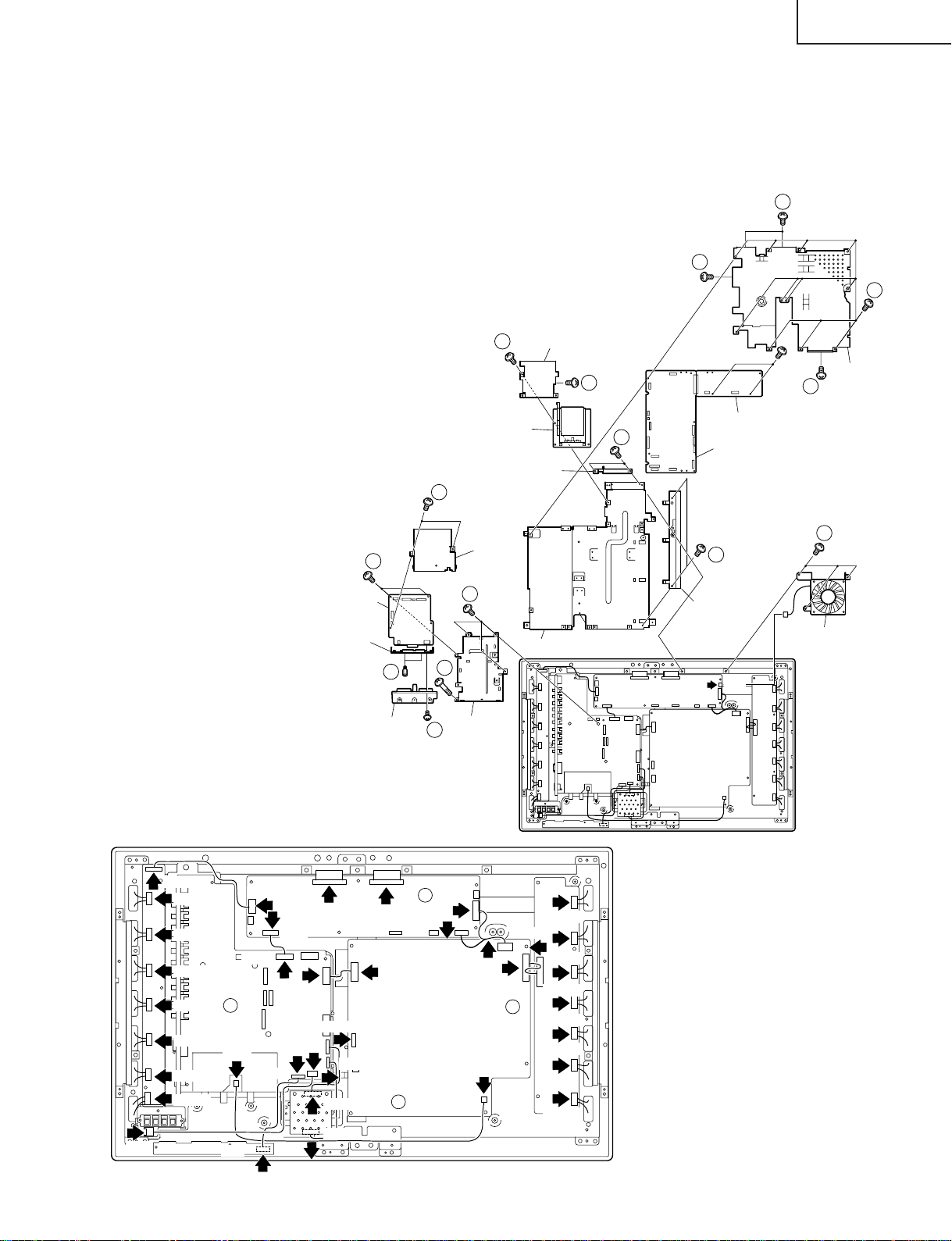
11. Remove the main, CPU and PC card PWBs.
1 1-1.Remove the one lock screw from flap door, and two lock screws from PWB shield, and detach the PC card
PWB.
11-2. Remove the 15 lock screws from the main PWB shield, and detach the main PWB shield and the main
PWB.
11-3. Remove the two lock screws from the frame cover, and detach the frame cover.
12. Detach the DVI PWB.
11-2
12-1. Remove the two lock screws from DVI PWB.
12-2. Remove the one lock screw, two screws and
11-2
two hexagon shaft screws from the DVI PWB,
and detach the DVI PWB.
12-3. Remove the four lock screws from HDMI
shield, and detach the HDMI shield.
13. Remove the three lock screws from the cooling
fan, and detach the cooling fan.
11-1
PWB Shield
11-1
Main PWB Shield
11-2
14. Disconnect all the connectors from all the PWBs.
CPU PWB
Main PWB
12-1
PC Card PWB
Flap Door
11-1
11-2
P202
CN7601
CN7602
CN7603
CN7604
CN7605
CN7606
CN7607
CN7608
14
P1101
P101
P7704
P3804
P3805
P2004
P5703
SC4651
P6001
12-2
DVI PWB
Angle
12-2
Frame Cover HDMI Shield
SC4652
CN707
P3801
P6003
CNA101
CNA102
14
12-2
14
P7707
12-3
P7705
DVI Shield
12-3
CN705
CN702
Main PWB Chassis
CN7501
CN704
14
13
11-3
Frame Cover
Cooling Fan
P7708
CN7502
CN7503
CN7504
CN7505
CN7506
CN7507
CN7508
15
Page 16
LC-26GA4D
LC-26GA4U
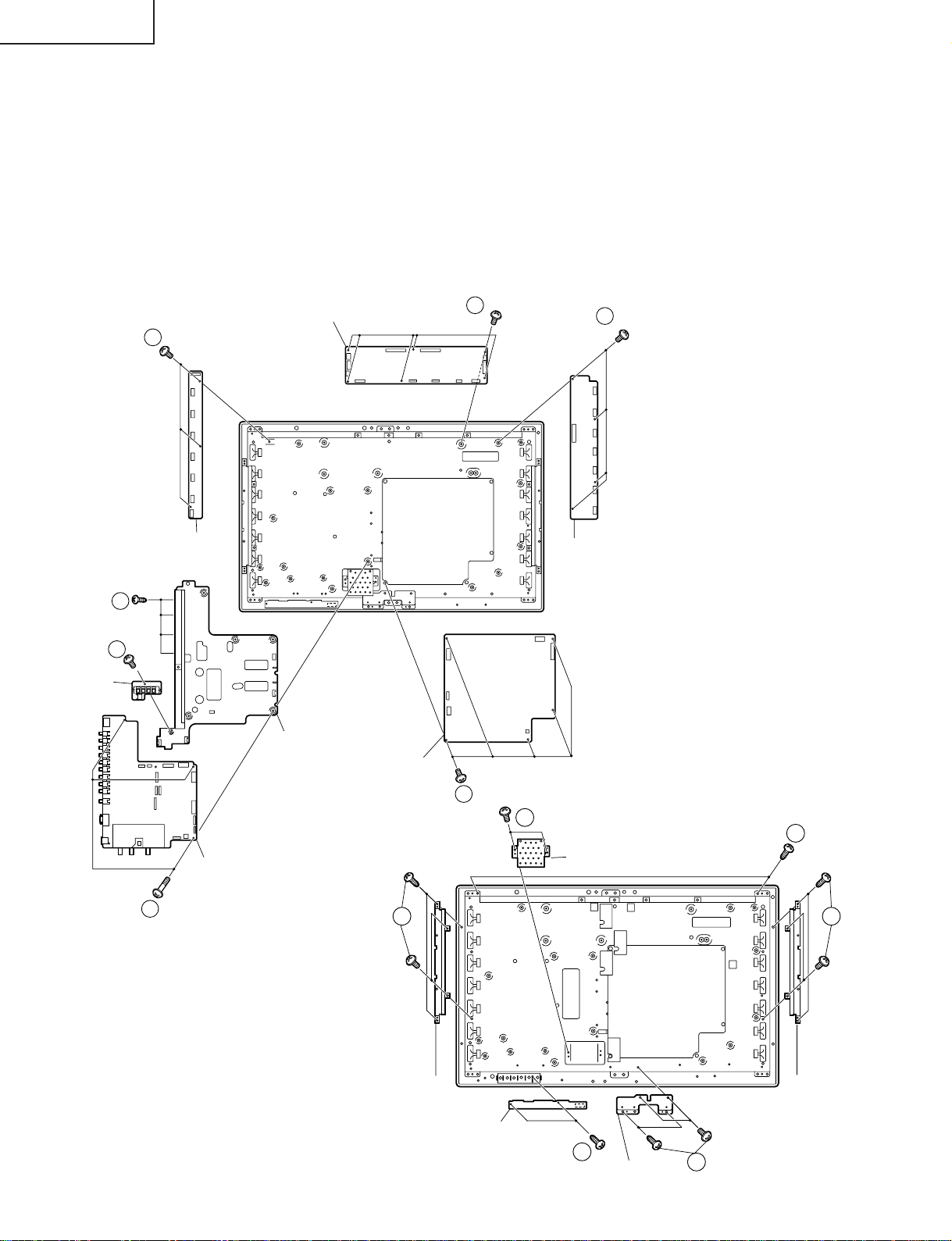
15. Remove the seven lock screws from the AV PWB, and detach the AV PWB.
16. Remove the one lock screw from EXT-SP PWB, and detach the EXT-SP PWB.
17. Remove the six lock screws from the LCD control PWB, and detach the LCD control PWB.
18. Remove the five lock screws from the power PWB, and detach the power PWB.
19. Remove the three lock screws from the inverter-GND PWB, and detach the inverter-GND PWB.
20. Remove the four lock screws from the inverter PWB, and detach the inverter PWB.
21. Remove the two lock screws from the 1-bit AMP. PWB, and detach the 1-bit AMP. PWB.
22. Remove the four lock screws form the speaker angle(right), and detach the speaker angle(right).
23. Remove the four lock screws form the speaker angle(left), and detach the speaker angle(left).
24. Remove the four lock screws form the center angle, and detach the center angle.
25. Remove the two lock screws from the RC/LED PWB, and detach the RC/LED PWB.
26. Remove the two lock screws from the LCD panel unit ass’y, and detach the LCD panel unit ass’y.
LCD Control PWB
19
17
20
EXT-SP PWB
Inverter-GND PWB
15
16
15
AV PWB
AV PWB Frame
POWER PWB
23
Inverter GND PWB
18
21
26
1-Bit Amp PWB
22
Speaker
Angle (R)
16
R/C, LED PWB
25
Center Angle
Speaker
Angle (L)
24
Page 17

27. Remove the four lock screws from the LCD panel unit, and detach the LCD panel unit.
28. Detach the reflection/deflection, prism and diffusion sheets and diffusion panel.
29. Remove the four lock screws from the lamp fixing holder, and detach the lamp fixing holer.
30. Detach the lamp unit from the lamp clip.
Lamp Holder (Top)
(CHLDZA328WJ01)
LC-26GA4D
LC-26GA4U
Back Shield
Sheet Spacer-A
(PSPAZA484WJZZ)
Sheet Spacer-S
(PSPAZA536WJZZ)
27
26" LCD Panel Unit
28
29
Sheet Spacer-S
Sheet Spacer-B
(PSPAZA535WJZZ)
Diffusion Panel
(PCOVUA026WJZZ)
Diffusion Sheet
(PSHEPA166WJZZ)
Prism Sheet
(PSHEPA165WJZZ)
Reflection/deflection Sheet
(PSHEPA164WJZZ)
29
Lamp Unit
(KLMP-A026WJZZ)
Lamp Holder (Top)
(CHLDZA328WJ01)
17
Page 18

LC-26GA4D
LC-26GA4U
ADJUSTMENT PROCEDURE
The adjustment values are set to the optimum conditions at the factory before shipping. If a value should
become improper or an adjustment is required due to part replacement, make an adjustment according to the
following procedure.
1. After replacement of any PWB unit and/or IC for repair, please note the following.
When replacing the following units, make sure to prepare the new units loaded with updated software.
CPU unit: DUNTKC427FE13
DVI/HDMI unit: DUNTKC267FE24
2.Upgrading of each microprocessor software
Caution: Never "POWER OFF" the unit when software upgrade is ongoing.
Otherwise the system may be damaged beyond recovery.
2-1 Software version upgrade
The model employs the following software.
» Main software
» Monitor microprocessor software (Display)
» Card microprocessor software
The main software and the monitor microprocessor software can be upgraded by using a general-purpose SD
memory card.
The card microprocessor software can be upgraded by using a PC card. The followings are the procedures
for upgrading, explained separately for each of the main software, the monitor microprocessor software and
the card microprocessor software.
2-2 Main software version upgrade
Get ready before you start
» SD memory card of 8MB or higher capacity
» PC running on Windows 98/98SE/ME/2000/XP operating system
» SD memory card reader/writer with USB connectivity and PC card adapter
» SD memory card formatting software
(Downloadable at http://panasonic.jp/support/audio/sd/download/sd_formatter.html)
18
Page 19
LC-26GA4D
LC-26GA4U
Preparations
To upgrade the main software, it is necessary to get ready the SD card for version upgrade before you start.
Follow the steps below and create the SD card for version upgrade.
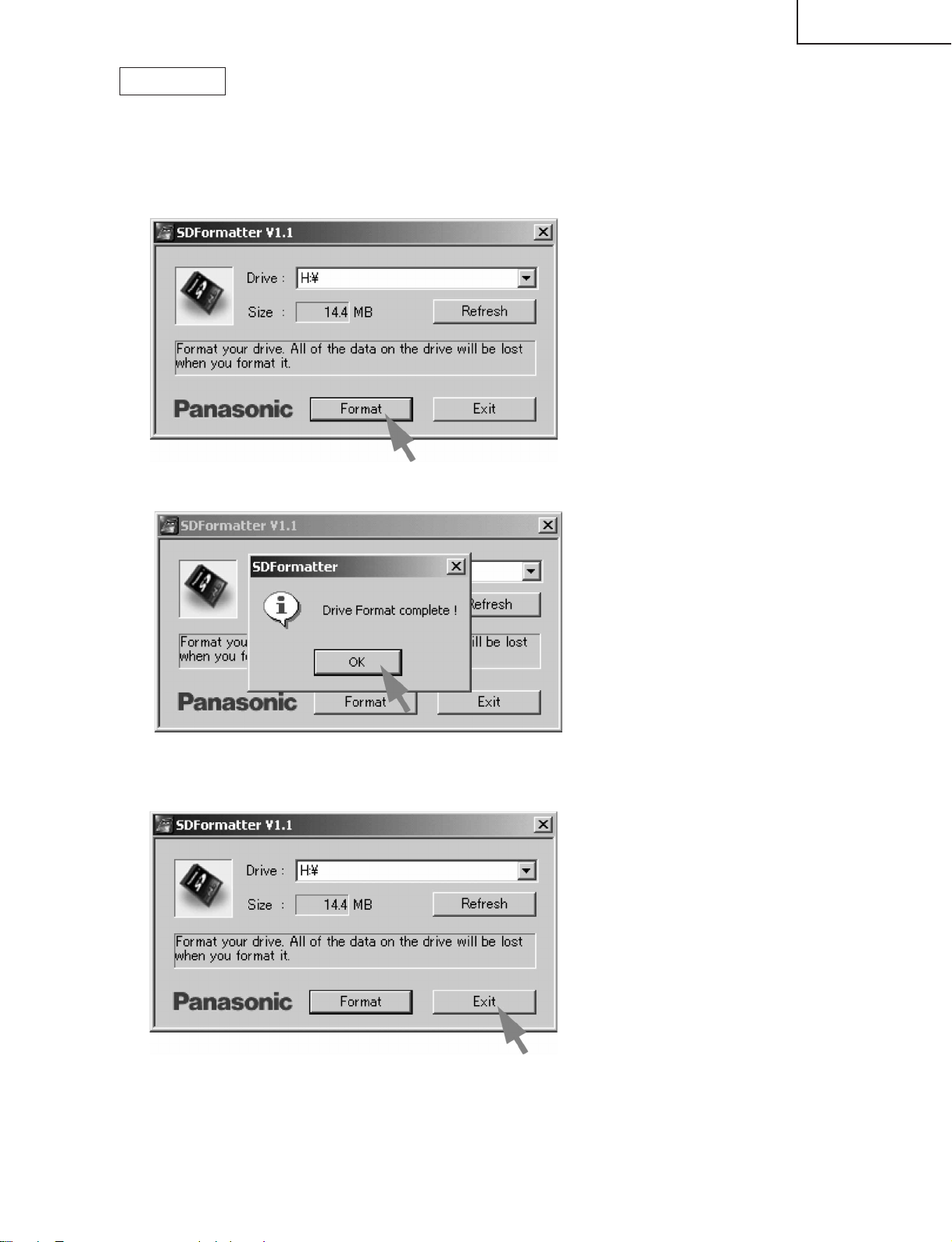
1 Insert the SD card into the SD card reader/writer. Start the SD card formatting software. Click [Format].
(When you have the drive options, select the drive where the SD card is inserted before you proceed.)
2 When the formatting is over, the following window appears. Click [OK].
3 Click [End] to finish the formatting.
Note: When you are done, take out the SD card once to make sure it is finished, and then insert it again.
4 Copy the binary image file KA1UAxxx.SDC (named temporarily) for version upgrade to the root directory
(folder) of the SD card drive.
Note: In the SD card drive, do not store other folders or unrelated files, or more than one binary image files for
version upgrade.
Now the SD card for version upgrade is ready.
19
Page 20
LC-26GA4D
LC-26GA4U
How to upgrade the software
1 Shut off the AC power (i.e. unplug the AC cord).
2 Insert the SD card for version upgrade (prepared as above) into the service socket located below left of the
right side cooling fan in the rear of the unit, in a way that the cut corner of the SD card comes at the righthand side.
Note: If the SD card is inserted in a wrong way, the card will go deep inside the unit beyond retrieval. Take due
care to insert the SD card correctly.
3 While depressing the SYSTEM RESET button located below the RS-232C connector in the rear left side of
the unit, turn on the AC power (i.e. plug in the AC cord).
Note: After the unit is started, you may release the SYSTEM RESET button.
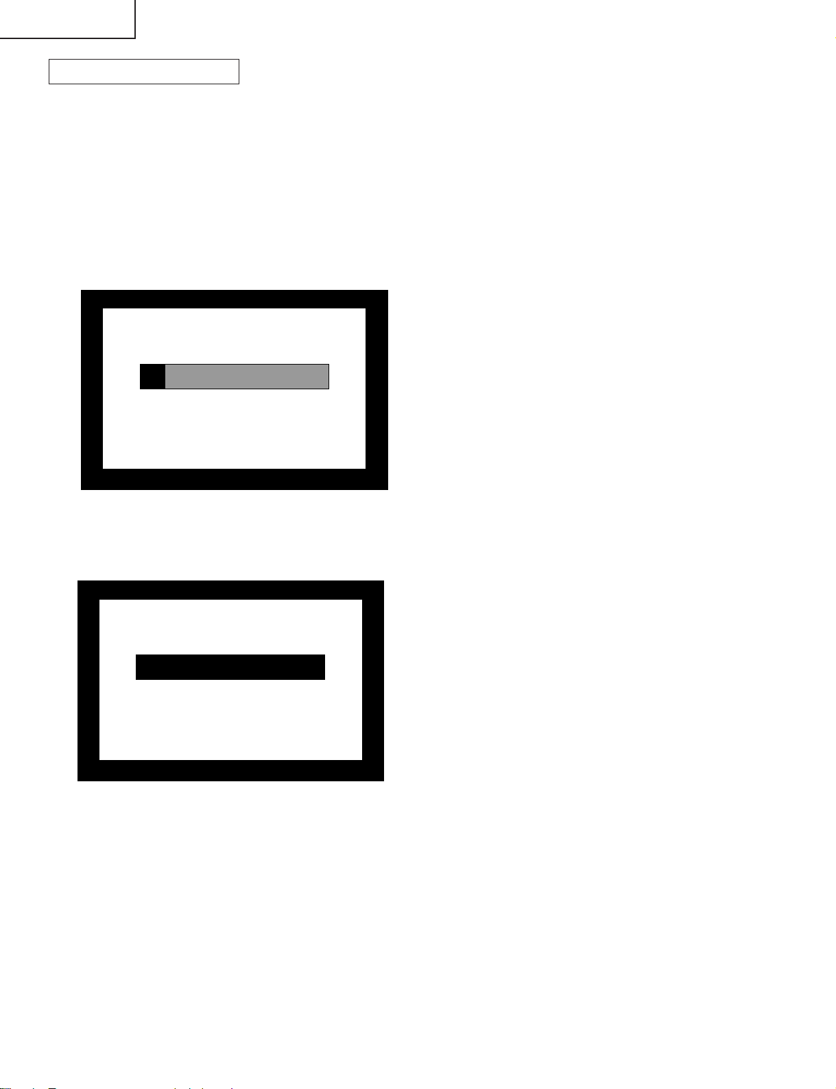
4 After the unit startup, the system upgrade screen as shown below appears within 10-20 seconds.
<SYSTEM UPGRADE>
Program OK NG
EEPROM
OK NG
12 %
US
5 Even a single failure in the process will trigger the upgrade failure screen as shown below. The word "NG"
changes to red for the item failed.
Note: In the event of a failure, repeat the upgrading process. If the process repeatedly fails, it is likely that the
hardware is troubled.
<UPGRADE FAILURE>
Program OK NG
100 %
EEPROM
OK NG
US
Ver 1.07(U 2004/04/01 2)
20
Page 21
LC-26GA4D
LC-26GA4U
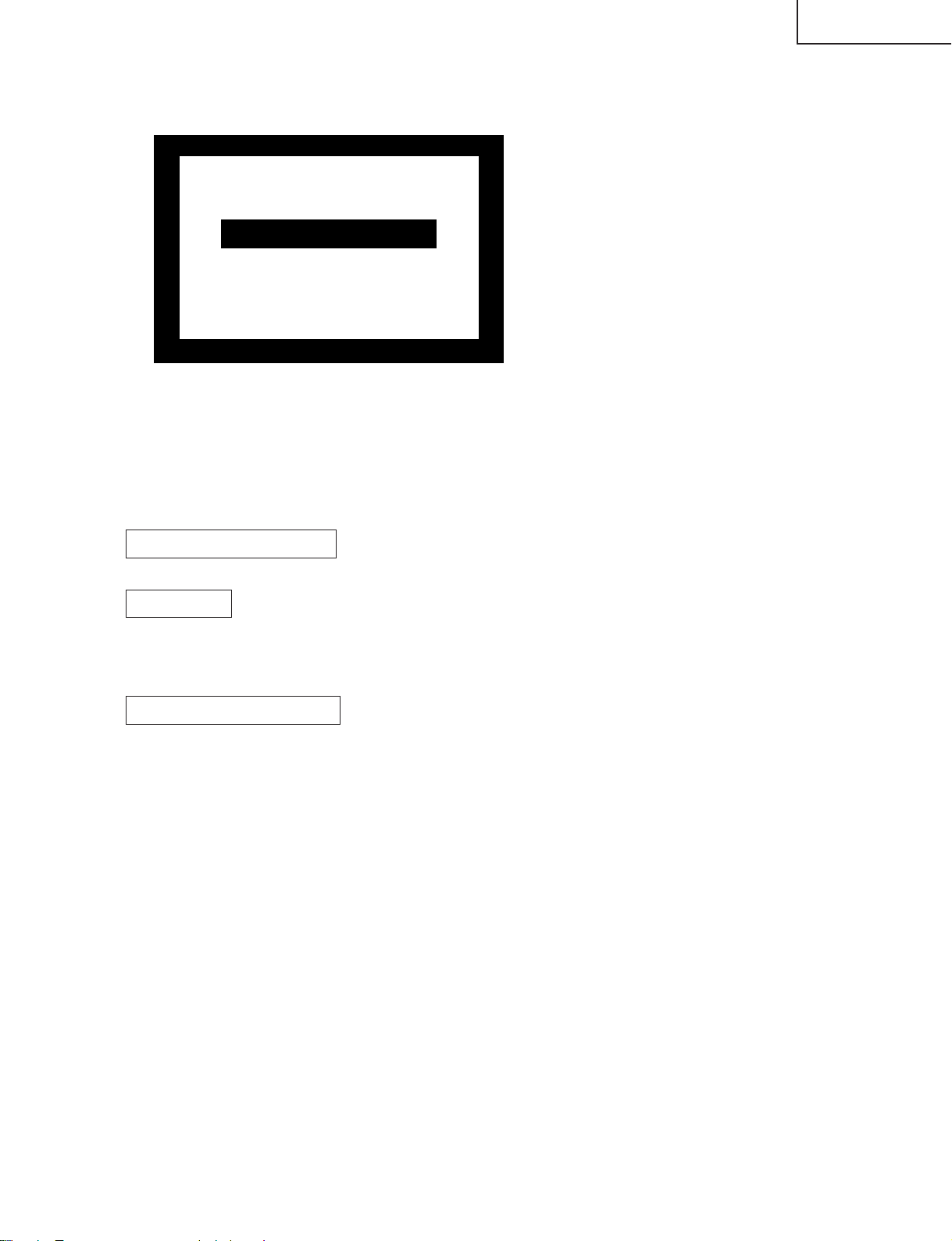
6 Upon completion of the whole process, the upgrade success screen as shown below appears. You can
check the new software version on this screen. The version information appears after the upgrade is
complete.
<UPGRADE SUCCESS>
Program OK NG
100 %
EEPROM
Ver 1.07(U 2004/04/01 2)
OK NG
US
7 Shut off the AC power to the unit (unplug the AC cord), and remove the SD card for version upgrade.
8 Now the software version upgrade is complete.
Note: When you are done with the software version upgrade, start the set, go to the top page of the adjustment
process screen and check the main software version information.
2-3 Monitor microprocessor software version upgrade
Get ready before you begin
Get ready the same items as listed in the "Main software version upgrade".
Preparation
Create the SD card for monitor microprocessor software version upgrade in the same manner as explained in
the "Main software version upgrade". Copy the binary image file for monitor microprocessor software version
upgrade to the SD card drive.
How to upgrade the software
During the monitor microprocessor software version upgrade, the progress of upgrading is not shown on the
display screen. The upgrading process is seen in the blinking of the power LED.
1 Shut off the AC power to the unit (i.e. unplug the AC cord).
2 Insert the SD card for version upgrade (prepared as above) into the service socket located below left of the
right side cooling fan in the rear of the unit, in a way that the cut corner of the SD card comes at the righthand side.
Note: If the SD card is inserted in a wrong way, the card will go deep inside the unit beyond retrieval. Take due
care to insert the SD card correctly.
3 While depressing the SYSTEM RESET button located below the RS-232C connector in the rear left side of
the unit, turn on the AC power (i.e. plug in the AC cord).
Note: After the unit is started, you may release the SYSTEM RESET button.
Caution!!
The moment this operation is done, the upgrading of the monitor microprocessor software starts.
While the upgrade is ongoing, never power off the unit. Otherwise the upgrade will fail and the
system may have a serious damage beyond recovery (inability to start).
21
Page 22

LC-26GA4D
LC-26GA4U
4 After the unit startup, the power LED starts blinking in green within 10-20 seconds.
5 Wait until the power LED stops blinking, the unit restarts automatically, and the normal startup screen
appears (it will take 2-3 minutes).
6 Shut off the AC power to the unit (unplug the AC cord), and remove the SD card for version upgrade.
7 Now the software version upgrade is complete.
Note: When you are done with the software version upgrade, start the set, go to the top page of the adjustment
process screen and check the monitor microprocessor software version information.
2-4 Card microprocessor software version upgrade
Get ready before you start
* CF (Compact Flash) of 8MB or higher capacity
* PCMCIA adapter for CF
* PC with PCMCIA slot running on Windows 98/98SE/ME/2000/XP operating system
Creating the PC card for version upgrade
Formatting the PC card
1 Insert the PC card into the PC card slot.
2 Open [My Computer] window, choose the relevant drive (e.g. H drive) and right-click it.
3 Select [Format] in the menu.
4 Under the file system, there are [FAT32] and [FAT] options. Select [FAT], and click [Start].
5 A dialog box requesting your confirmation appears. Click [OK].
6 Wait until the formatting is over. Then click [OK].
After this, click [Close].
Creating a new "boot" folder directly under the card root directory
1 * Create H:¥boot if the card is in H:¥drive.
2 Click [File], point to [Rename], and click [Folder].
3 Rename the folder as [boot].
Copying the version upgrade file to the PC card
Using a drag-and-drop action, copy the "aqb5cu.img" (temporarily named) file for version upgrade to the "boot"
folder.
Removing the PC card
1 Click [Safely removing hardware] in the task bar, select [PCMCIA IDE/ATAPI Controller], and click [Stop].
2 Select PC card in [Stop hardware device], and click [OK].
3 After confirming that you can safely remove the hardware, remove the PC card.
Now the PC card for version upgrade is ready.
22
Page 23
LC-26GA4D
LC-26GA4U
How to upgrade the software
When you are done with the version upgrade, check the software version information in the adjustment process
mode.
1 Turn off the power. Insert the PC card into the slot of the set, which was prepared in the above "Creating
the PC card for version upgrade".
2 Turn on the power.
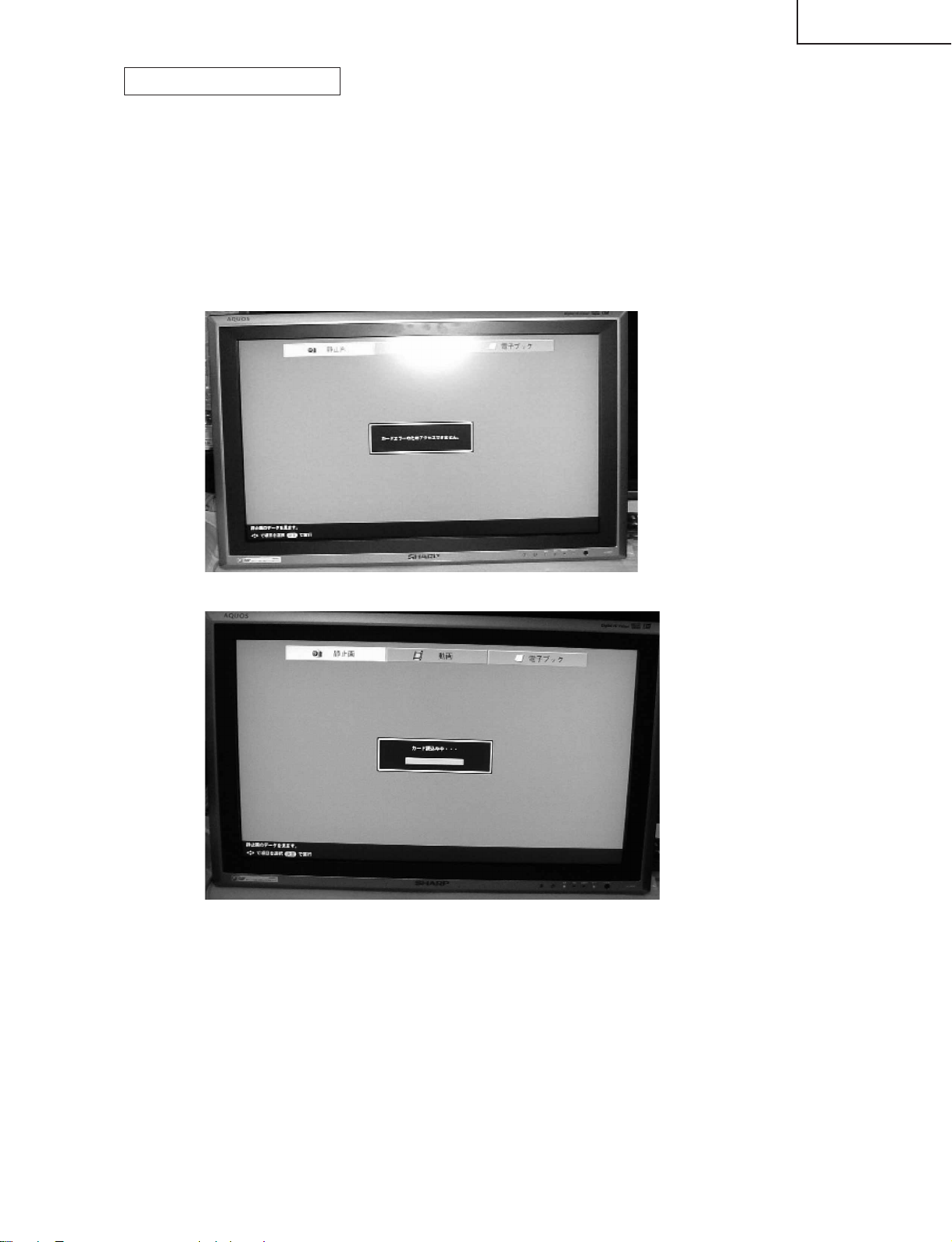
3 Wait until the process ends (about 2 minutes). Entering the card mode is not necessary.
* In case the card mode is entered, nothing appears on the screen for about 50 seconds after power-on.
"Card error" is displayed on the screen.
The action has ended successfully when the display is replaced by "Loading from the card".
*If the action has failed, turn off the power and repeat the steps 1 thru 3.
23
Page 24
LC-26GA4D
LC-26GA4U
3.Entering and exiting the adjustment process mode
(1) Before entering the adjustment process mode, press the "TV RESET" button or execute the AV position
RESET in the video adjustment menu.
(2) While holding down the "VOL (–)" and "INPUT" keys at a time, press the POWER switch of the main unit to
turn on the power. (The "VOL (–)" and "INPUT" keys should be pressed and held until the display appears.)
The letter “K” appears on the screen.
(3) Next, hold down the "VOL (–)" and "CH (Ù)" keys at a time.
Multiple lines of blue characters appearing on the display indicate that the unit is now in the adjustment
process mode.
When you fail to enter the adjustment process mode (the display is the same as normal startup), retry the
procedure.
(4) To exit the adjustment process mode after the adjustment is done, unplug the AC cord from the outlet to
make a forced shutdown. (When the power was turned off with the remote controller, once unplug the AC
cord and plug it again. In this case, wait 10 seconds or so before plugging.)
Caution: Use due care in handling the information described here lest your users should
know how to enter the adjustment process mode. If the settings are tampered in this mode,
unrecoverable system damage may result.
4.Remote controller key operation and description of display in adjustment process
mode
(1) Key operation
Remote controller key Main unit key Function
CH (Ù/ù) CH (Ù/ù) Moving an item (line) by one (UP/DOWN)
VOL (+/–) VOL (+/–) Changing a selected item setting (+1/–1)
Cursor (UP/DOWN) Turing a page (PREVIOUS/NEXT)
Cursor (LEFT/RIGHT) Changing a selected line setting (+10/–10)
INPUT Input switching (toggle switching)
(TV→INPUT1→INPUT2→INPUT3→INPUT4→
INPUT5→CARD)
ENTER Executing a function
* Input mode is switched automatically when relevant adjustment is started so far as the necessary input
signal is available.
(2) Description of display
(2) Current page title
(1) Current page /
Total pages
(3) Currently selected input
(4) Current color TV system
(5) Destination
1/15
MAIN Version
CARD Version
Monitor Version
EQ DATA CHECKSUM
STANDBY CAUSE
FAN STATUS
[INFO]
TUNER
1.XX( J 2004/XX/XX X )
1.XX
3.XX
A15E
a
ROTATE
N358
24
USA
Adjustment process menu header
(7) Parameters
Page 25
5. List of adjustment process mode menu
The character string in brackets [ ] will appear as a page title in the adjustment process menu header.
Page Line Item Description Remarks (adjustment detail, etc.)
1 [INFO]
1 MAIN Version
2 CARD Version Card unit version Card unit microprocessor software version
3 Monitor Version Monitor version Obtained from the monitor. (Displays panel size and type as well.)
4 EQ DATA CHECKSUM Audio data checksum Audio data checksum display
5 STANDBY CAUSE Standby cause Last status which caused standby
6 FAN STATUS Fan
2 [INIT]
1 INDUSTRY INIT
2 HOTELMODE Hotel mode settings
3 Center Acutime
4 RESET Reset
5 BacklightAcutime
6 RESET Reset
7 VIC XPOS
8 VIC YPOS
9 VIC COLOR
10 VIC SIGNAL_TYPE
11 VIC READ
3 [N358MAIN]
1 N358 ALL ADJ N358MAIN+SUB+TUNER Auto N358 Main, Sub and Tuner DAC adjustments
2 N358 MAIN ADJ Auto ALL Auto N358 Main video adjustment
3 N358 SUB ADJ Auto ALL Auto N358 Sub video adjustment
4 TUNER DAC ADJ IC400
5 N358 MAIN CONTRAST IC400 Contrast
6 N358 MAIN Cb GAIN IC400 Cb gain
7 N358 MAIN Cr GAIN IC400 Cr gain
8 N358 SUB CONTRAST IC500 Contrast
9 N358 SUB Cb GAIN IC500 Cb gain
10 N358 SUB Cr GAIN IC500 Cr gain
11 TUNER A DAC TUNER-A DAC Tuner DAC
12 TUNER B DAC TUNER-B DAC Tuner DAC
4 [N358SUB]
1
TUNER VCHIP TEST(69ch)
2 N358 SUB CONTRAST IC500 N358 Sub video contrast
3 N358 SUB Cb GAIN IC500 Cb gain
4 N358 SUB Cr GAIN IC500 Cr gain
5
TUNER VCHIP TEST(10ch)
6
TUNER VCHIP TEST(15ch)
5 [COMP15KMAIN]
1 COMP15K ALL ADJ Auto ALL Auto COMP15K Main + Sub adjustments
2 COMP15KAD MAIN ADJ Auto ALL Auto COMP15K Main video adjustment
3 COMP15K MAIN ADJ Auto ALL
4
COMP15K MAIN CONTRAST
5 COMP15K MAIN Cb GAIN IC400 Cb gain
6 COMP15K MAIN Cr GAIN IC400 Cr gain
7 COMP15K Y OFFSET
8 COMP15K Cb OFFSET
9 COMP15K Cr OFFSET
10
COMP15K SUB CONTRAST
11 COMP15K SUB Cb GAIN IC500 Cb gain
12 COMP15K SUB Cr GAIN IC500 Cr gain
6 [COMP15KSUB]
1 COMP15K SUB ADJ Auto ALL Auto COMP15K Sub video adjustment
2
COMP15K SUB CONTRAST
3 COMP15K SUB Cb GAIN IC500 Cb gain
4 COMP15K SUB Cr GAIN IC500 Cr gain
7 [HDTV]
1 HDTV ADJ Auto HDTV video adjustment
2 CONTRAST IC3700 Contrast
3 Cb GAIN IC3700 Cb gain
4 Cr GAIN IC3700 Cr gain
5 HDTV Y OFFSET
6 HDTV Cb OFFSET
7 HDTV Cr OFFSET
Main microprocessor version
Initialization to factory settings
Accumulated AVC operation time
Accumulated monitor operation time
Auto ALL
IC400 Contrast
IC500 Contrast
IC500 Contrast
Version display
Initialization to factory settings
Reset by initialization
Not reset by initialization
LC-26GA4D
LC-26GA4U
25
Page 26
LC-26GA4D
LC-26GA4U
8 [DVI ANALOG]
1 DVI ANALOG Auto DVI analog video adjustment
2 R CUTOFF IC3700
3 G CUTOFF IC3700
4 B CUTOFF IC3700
5 R DRIVE IC3700
6 G DRIVE IC3700
7 B DRIVE IC3700
9 [DVI DIGITAL]
1 DVI DIGITAL Auto DVI digital video adjustment
2 CONTRAST IC3700 Contrast
3 R CUTOFF
4 G CUTOFF
5 B CUTOFF
6 R DRIVE
7 G DRIVE
8 B DRIVE
10 [M GAMMA]
1 MONITOR R GAMMA LO Monitor W/B adjustment
2 MONITOR G GAMMA LO
3 MONITOR B GAMMA LO
4 MONITOR R GAMMA HI
5 MONITOR G GAMMA HI
6 MONITOR B GAMMA HI
7 GAMMA WRITE Writing in monitor gamma table
8 GAMMA RESET Reset of monitor gamma table
11 [M GAMMA R]
1 MONITOR R GAMMA 1
2 MONITOR R GAMMA 2
3 MONITOR R GAMMA 3
4 MONITOR R GAMMA 4
5 MONITOR R GAMMA 5
6 MONITOR GAMMA 6
7 GAMMA WRITE
8 GAMMA RESET
12 [M GAMMA G]
1 MONITOR G GAMMA 1
2 MONITOR G GAMMA 2
3 MONITOR G GAMMA 3
4 MONITOR G GAMMA 4
5 MONITOR G GAMMA 5
6 MONITOR B GAMMA 6
7 GAMMA WRITE
8 GAMMA RESET
13 [M GAMMA B]
1 MONITOR B GAMMA 1
2 MONITOR B GAMMA 2
3 MONITOR B GAMMA 3
4 MONITOR B GAMMA 4
5 MONITOR B GAMMA 5
6 MONITOR B GAMMA 6
7 GAMMA WRITE
8 GAMMA RESET
14 [PATTERN]
1 CVIC PATTERN
2 GPU PATTERN
15 [ETC]
1 EEP SAVE
2 EEP RECOVER
3 CARD REC INPUT
4 STANDBY CAUSE RESET
CVIC-generated internal pattern display
SEINE-generated internal pattern display
Storage of adjustment value
Retrieval of adjustment value
Permission of card recording by external input source
CVIC internal pattern display
SEINE internal pattern display
Saving adjustment value in storage area
Retrieving adjustment value from storage area
26
Page 27
6. Special features
* STANDBY CAUSE (Page 1/15)
Display of a cause (code) of the last standby
The cause of the last standby is recorded in EEPROM whenever possible.
Checking this code will be useful in finding a problem when you repair the troubled set.
* EEP SAVE (Page 15/15)
Storage of EEP adjustment value
* EEP RECOVER (Page 15/15)
Retrieval of EEP adjustment value from storage area
7. Video signal adjustment procedure * Adjustment process mode menu is listed in section 5.
(1) Signal check
Signal generator level adjustment check (Adjustment to the specified level)
» Composite signal : 0.714Vp-p ± 0.02Vp-p (Pedestal to white level)
» 15K component signal : Y level : 0.714Vp-p ± 0.02Vp-p (Pedestal to white level)
PB, PR level
» 33K component signal : Y level : 0.714Vp-p ± 0.02Vp-p (Pedestal to white level)
PB, PR level
» DVI-I (analog RGB) signal : RGB level : 0.714Vp-p ± 0.02Vp-p (Pedestal to white level)
: 0.7Vp-p ± 0.02Vp-p
: 0.7Vp-p ± 0.02Vp-p
LC-26GA4D
LC-26GA4U
(2) Entering the adjustment process mode
Enter the adjustment process mode according to the steps described in section 3.
(3) N358 composite signal adjustment (Main, Sub and Tuner)
Adjustment item Adjustment conditions Adjustment procedure
1 Adjustment N358 signal
US-10ch
2 Auto adjustment Page 3/15
performance
Feed the NTSC split field color bar signal (75% color saturation) to INPUT
1 input.
Feed the RF signal (by use of US-10ch) to TUNER-A and TUNER-B.
[Video input signal] [US-10CH]
↑100% white ↑100% white
Bring the cursor on [ËN358 ALL ADJ] and press [ENTER].
[ËN358 ALL ADJ FINISH] appears when finished.
27
Page 28

LC-26GA4D
LC-26GA4U
(4) Component 15K signal adjustment (Main and Sub)
Adjustment item Adjustment conditions Adjustment procedure
1 Adjustment 480i signal
Feed the 100% color bar signal to VIDEO 1 component input.
↑100% white
2 Auto adjustment Page 5/15
performance
(5) Component 33K signal adjustment
Adjustment item Adjustment conditions Adjustment procedure
1 Adjustment 1080i signal
2 Auto adjustment Page 7/15
performance
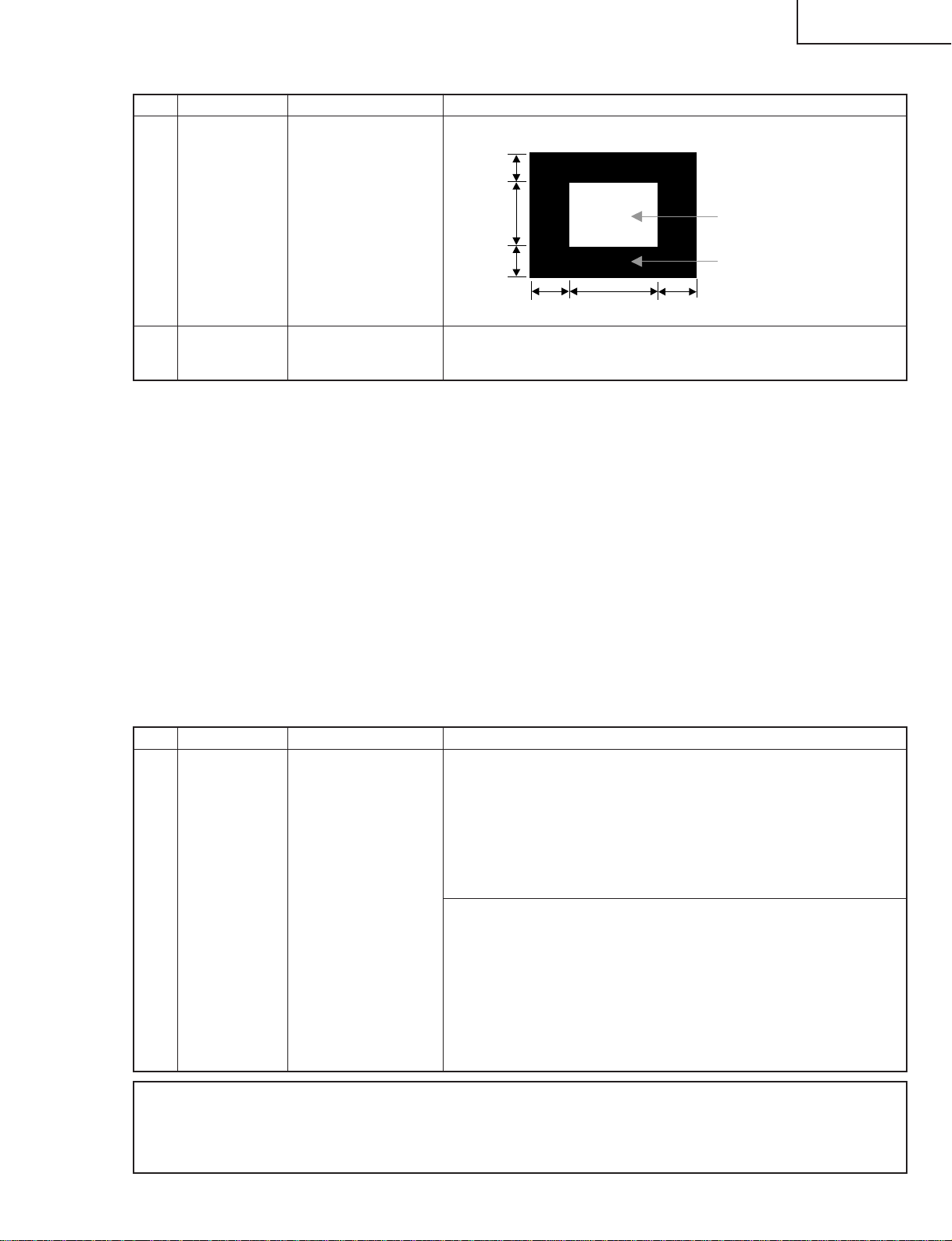
(6) DVI-I (analog) signal adjustment
Bring the cursor on [ËCOMP 15K ALL ADJ] and press [ENTER].
[ËCOMP 15K ALL ADJ FINISH] appears when finished.
Feed the 100% color bar signal to VIDEO 1 component input.
↑100% white
Bring the cursor on [ËHDTV ADJ] and press [ENTER].
[ËHDTV ADJ FINISH] appears when finished.
Adjustment item Adjustment conditions Adjustment procedure
1 Adjustment DVI-I (analog)
2 Auto adjustment Page 8/15
performance
Feed the 100% white 1/2 window pattern signal to DVI-I (analog) input.
1/4
1/2
1/4
1/4
Bring the cursor on [ËDVI ANALOG ADJ] and press [ENTER].
[ËDVI ANALOG ADJ FINISH] appears when finished.
1/2
28
100% White
0% Black
1/4
Page 29
(7) DVI-I (digital) signal adjustment
Adjustment item Adjustment conditions Adjustment procedure
1 Adjustment DVI-I (digital)
LC-26GA4D
LC-26GA4U
Feed the 100% white 1/2 window pattern signal to DVI-I (digital) input.
1/4
2 Auto adjustment Page 9/15
performance
1/2
1/4
1/4
Bring the cursor on [ËDVI DIGITAL ADJ] and press [ENTER].
[ËDVI DIGITAL ADJ FINISH] appears when finished.
1/2
1/4
100% White
0% Black
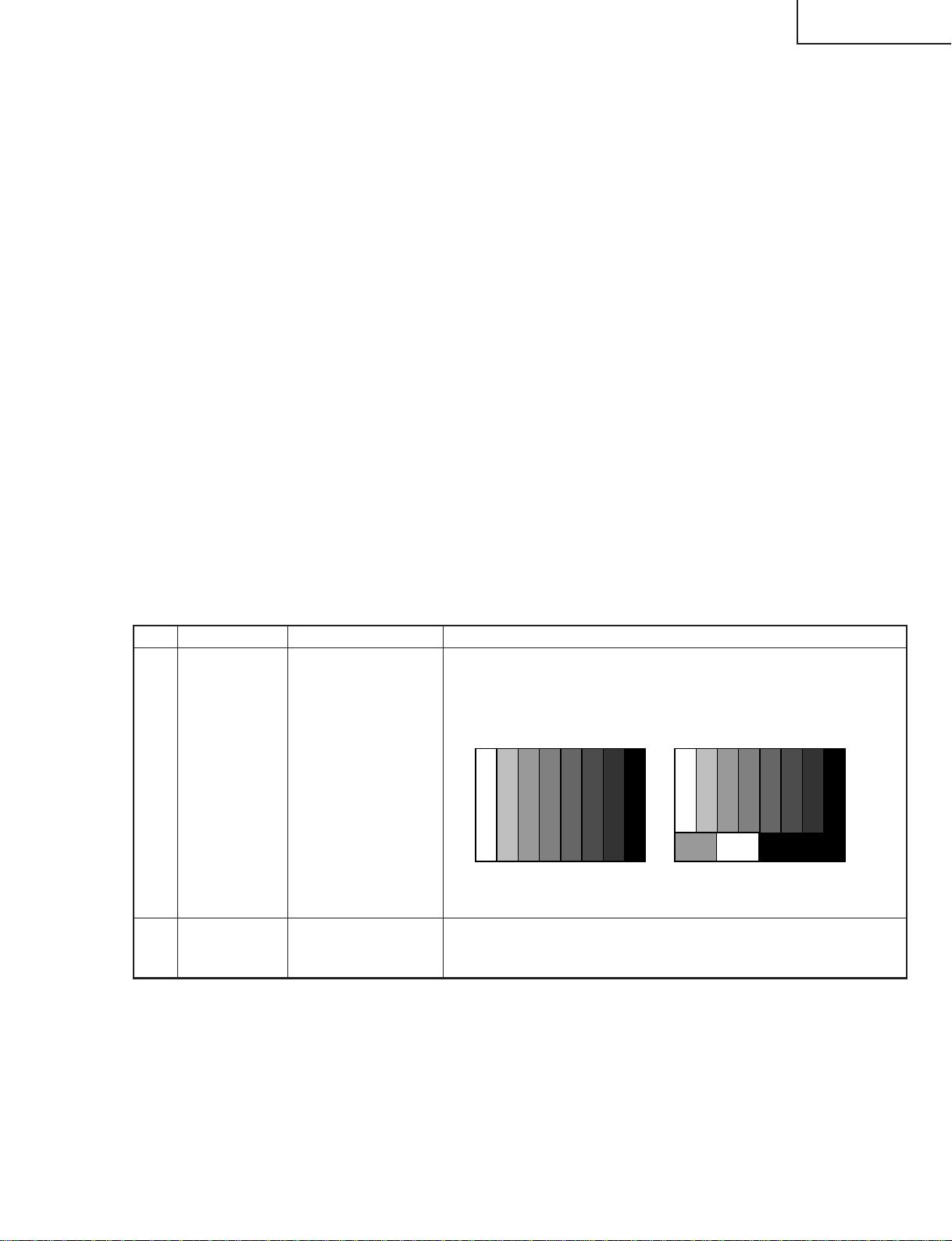
8. White balance adjustment
Start the set and perform a white balance adjustment on the display.
» Procedure
» Bring up the adjustment screen (High side: 200 gradations, Low side: 48 gradations).
» Adjust [R GAMMAL], [G GAMMAL] and [B GAMMAL] so that 48-gradation pattern becomes normal.
* Adjust the chromaticity of the Low pattern (on the right of the display) so that it is set to x=0.284 and
y=0.292.
» Adjust [R GAMMAH], [G GAMMAH] and [B GAMMAH] so that 200-gradation pattern becomes normal.
* Adjust the chromaticity of the High pattern (on the left of the display) so that it is set to x=0.284 and
y=0.292.
9. Initialization to factory settings
Caution: When initialization is performed, all user setting data including the channel settings are
initialized. Be cautious when making this adjustment.
(The adjustments done in the adjustment process mode are not initialized.)
Adjustment item Adjustment conditions Adjustment procedure
1 Initialization
Enter the adjustment process mode.
Bring the cursor on to [INDUSTRY INIT] in page 2/15.
Set to [ON] using [VOL] key, and press [ENTER] to execute the
initialization.
When the initialization is complete, the adjustment process mode screen is
automatically replaced by the TV's 1ch screen.
* Never shut off the power during the initialization process.
The following settings are initialized in this adjustment.
1. User setting
2. Channel data (e.g. broadcast frequencies)
3. Password data
4. Operation time
5. Maker's optional setting
6. Auto installation flag
7. V-CHIP block setting
After the adjustment, cancel the adjustment process mode.
To exit the adjustment process mode, unplug the AC cord from the outlet to make a forced
shutdown. (When the power was turned off with the remote controller, once unplug the AC cord
and plug it again. In this case, wait 10 seconds or so before plugging.)
29
Page 30
LC-26GA4D
LC-26GA4U
10. Display adjustment procedure
1. Adjusting procedure
Entering the adjustment process mode → COM BIAS adjustment
2. Entering and exiting the adjustment process mode
(1) Before entering the adjustment process mode, press the "TV RESET" button or execute the AV position
RESET in the menu video adjustment.
(2) While holding down the "VOL (+)" and "CH (Ù)" keys at a time, press the "POWER" key of the main
unit to turn on the power. (The "VOL (–)" and "INPUT" keys should be pressed and held until the display
appears.)
The letter "K" appears on the screen.
(3) Next, press the remote controller key (VOL, CH, etc.).
Multiple lines of red characters appearing on the display indicate that the unit is now in the adjustment
process mode.
When you fail to enter the adjustment process mode (the display is the same as normal startup), retry
the procedure.
(4) To exit the adjustment process mode after the adjustment is done, unplug the AC cord from the outlet to
make a forced shutdown. (When the power was turned off with the remote controller, once unplug the
AC cord and plug it again. In this case, wait 10 seconds or so before plugging.)
Caution: Use due care in handling the information described here lest your users should know
how to enter the adjustment process mode. If the settings are tampered in this mode,
unrecoverable system damage may result.
3. Adjustment process mode key operation table
Key Function 1 (when on the left side of a page) Function 2 (when changing a numeric value)
Cursor UP
Cursor DOWN
Cursor RIGHT
Cursor LEFT
ENRER
INPUT
CH_UP
CH_DOWN
VOL_UP
VOL_DOWN
Moving up by one item or moving to the previous
page (when at the top)
Moving down by one item or moving to the next
page (when at the bottom)
Moving to the right by one item or moving to
another page (in the case of the initial page)
Moving to the left by one item or moving to
another page (in the case of the initial page)
test patterm off
Moving to the next page
Moving up by one item or moving to the previous
page (when at the top)
Moving down by one item or moving to the next
page (when at the bottom)
Moving to the right by one item or moving to
another page (in the case of the initial page)
Moving to the left by one item or moving to
another page (in the case of the initial page)
Incrementing the adjustment value by one or
executing the item (in the case of W or R item)
Decrementing the adjustment value by one or
executing the item (in the case of W or R item)
Moving to the right by one item
Moving to the left by one item
Executing the item (in the case of W or R item)
Moving to the next page
Incrementing the adjustment value by one or
executing the item (in the case of W or R item)
Decrementing the adjustment value by one or
executing the item (in the case of W or R item)
Moving to the right by one item
Moving to the left by one item
30
Page 31

4. COM BIAS adjustment
Shift to the [COM BIAS] item with the cursor UP/DOWN key and select a numeric value with the cursor
RIGHT/LEFT key.
Changing the numeric value with the cursor UP/DOWN key will make appear the test pattern. Make an
adjustment so that the flicker near the center of the screen is minimized.
Adjusting procedure by use of [RS-232C]
» Get ready the PC with COM port (RS-232C) running on Windows 95/98/ME/2000/XP operating system,
as well as the RS-232C cross cable.
» Start the unit with the RS-232C cable connected.
» Start the terminal software. (The freeware readily available on the Internet will do.)
» Make the following settings.
Baud rate 9600
Data 8 bits
Parity None
Stop bit 1 bit
Flow control Not implemented
» If the settings are correct, the terminal software indicates "ERR" against pressing of the "ENTER" key.
» After the settings are done correctly, it is possible to make an adjustment by typing in the command
shown in the table below and pressing the "ENTER" key on the keyboard.
LC-26GA4D
LC-26GA4U
Command entry is successful if the terminal software indicates "OK" when the "ENTER" is pressed.
If "ERR" is shown, retry to enter the command.
RS232C command table
Command Function Remarks
MSET1001
MOFR****
MOFG****
MOFB****
MGAR****
MGAG****
MGAB****
MINF0000
MINF0001
MINF0002
Starting the white balance adjustment
Adjusting the R GAMMA L value
Adjusting the G GAMMA L value
Adjusting the B GAMMA L value
Adjusting the R GAMMA H value
Adjusting the G GAMMA H value
Adjusting the B GAMMA H value
Displaying the R GAMMA table
Displaying the G GAMMA table
Displaying the B GAMMA table
Ending the adjustment with a numeric value
other than 1001
Range: 0000~0255
Range: 0000~0255
Range: 0000~0255
Range: 0000~0255
Range: 0000~0255
Range: 0000~0255
31
Page 32

LC-26GA4D
LC-26GA4U
5. Lamp error detection
5-1. Feature description
This liquid-crystal color TV incorporates a lamp error detection feature (lamp error detection) that
automatically turns OFF the power for safety under abnormal lamp or lamp circuit conditions.
If anything is wrong with the lamp or lamp circuit or when the lamp error detection feature is activated for
some reason, the following will result.
1 The power of TV main body is turned OFF about six seconds after it is turned ON. (The power LED on
the front of the TV turns red from green and keeps blinking in red (ON for 240ms and OFF for 1sec)).
2 If occurs five times consecutively, it becomes impossible to turn ON the power. (The power LED keeps
blinking in red (ON for 240ms and OFF for 1sec)).
5-2. Measures
1) Checking with lamp error detection OFF
While the POWER switch is off, hold down the "CH (Ù)" and "VOL (+)" keys and then turn the POWER
switch on. The display will run in the "Display process mode" ("<K>" will appear).
If there is a problem with a lamp or a lamp circuit, the lamp will go out. (The power LED is green.)
Then, you can check the operation to see if the lamp and lamp circuit are abnormal.
2) Resetting the lamp error count
After you have finished checking whether the lamp and lamp circuit are abnormal, reset the lamp error
count. If a lamp error is detected five consecutive times, the power cannot be turned on.
Therefore, move to the [L ERR RESET] line, the 5th line on the first page of the "Display process mode",
using the Cursor UP/DOWN key. Then, reset the [L ERR RESET] value using the Cursor RIGHT/LEFT
key. In this case, press the Cursor UP/DOWN key to reset it to "0".
Table of contents of adjustment process mode Page 0
0123456789ABCDEF
0SERVI CE I 26GA4
1 GRAYLEVEL 100
→
2 COMBIAS 200
3 VLSBIAS 041
4 L ERR RESET 5
5LCD
6PATTERN
7 MOTOR AND FAN
8OTHER
9 VER M203
After resetting to "0", perform an operational check to ensure that the lamp error detection feature is not activated.
Values specific to each display
Reset to "0
"
32
Page 33

LC-26GA4D
LC-26GA4U
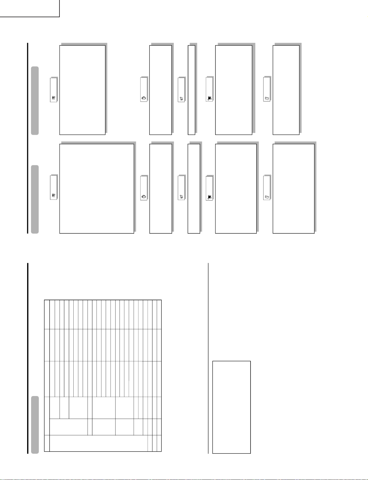
6. List of adjustment process modes (Display)
(Examples)
Table of contents of adjustment process mode Page 0
0123456789ABCDEF
0SERVI CE I 26GA4
1 GRAYLEVEL 100
→
2 COMBIAS 200
3 VLSBIAS 041
4 L ERR RESET 0
5LCD
6PATTERN
7 MOTOR AND FAN
8OTHER
9 VER M203
LCD Page 1 LCD Page 4
0123456789ABCD 0123456789ABCD
0LCD1 0 LCD4
1MODE PC0
→
2PWMCTRL 3
3 PWMFREQ 1279 11
4 PWMDUTY1 0116 12 53
5 PWMDUTY2 0116 13 58
6 PHASEDIF 000 14
7PCLK1 0
8PCLK2 0
9 9
1OPC
→
2OPC
3OPC
4OPC
5OPC
6OPC
7OPC
8OPC
9
10
15
16
40
45
49
62
62
74
LCDPage 2
0123456789ABCD 0123456789ABCD
0LCD2 0 LCD5
1MODE PC0
→
2 QS SW 2 VL0 0941
3 QS D1 084
4 QS D2 096 4 VL31 0694
5 QS D3 106 5 VH63 0473
6 QS D4 118 6 VL63 0621
7 QS D5 132 7 VH95 0509
8 QS D6 147 8 VL95 0503
9 QS D7 162 9
LCD Page 3
0123456789ABCD 0123456789ABCD
0LCD3 LCD6
1OPC0 00
→
2OPC1
3 OPC 2 VH159
4 OPC 3 VL159 0495
5OPC4 0627
6 OPC 5 VL191 0443
7OPC6 0795
8 OPC 7 VL247 0153
9OPC8
1
05
09
13
18
22
27
31
36 9
LCD Page 5
1 VH0 0166
→
3 VH31 0417
LCD Page 6
0
1
VL127
→
2
VL127 0550
3
4
5
VH191
6
7
VH247
8
0535
0581
33
Page 34

LC-26GA4D
LC-26GA4U
PATTERN Page1 OTHER Page 1
0123456789ABCD 0123456789ABCD
0PATTERN1 OTHER1
1PATTERN1 00
2PATTERN2 00 W0
3 PATTERN3 00 LCD DATA 0000
4PATTERN4 00
5 5 EEP C 0000000
6 6
7 7
8 8
9 9
PATTERN Page 2 OTHER Page 2
0123456789ABCD 0123456789ABCDEF
0PATTERN2 OTHER2 26GD1
1 RESERVE 0 1 ERR STOP 0
2 RESERVE 0 MODEL 0
3 EMOCON 0
4
5 STEMP AD 106
6 PC AD 208
7
8
9
0
1CLRMODE 0
2
3
4R0W0
R0W0
0
1C
2
3
4
5
6
MOTOR FAN Page 1 OTHER Page 3
0123456789ABCD 0123456789ABCD
0MOTOR FAN OTHER3
1 RESERVE 0 1TIMEOUTON 1
2 RESERVE 0 IO70 10000111
3 RESERVE 0 IO72 11001110
4 RESERVE 0 000000000000
5 RESERVE 0 040330101147
6 RESERVE 0 ETC 201221010
7 FAN START 224 7 RAM EEP 4A 00
8 FAN STOP 230 8 MICOM 00 0000
9T
0
1
2
3
4
5
6
7
8
9EMP ERR 055 9
34
Page 35

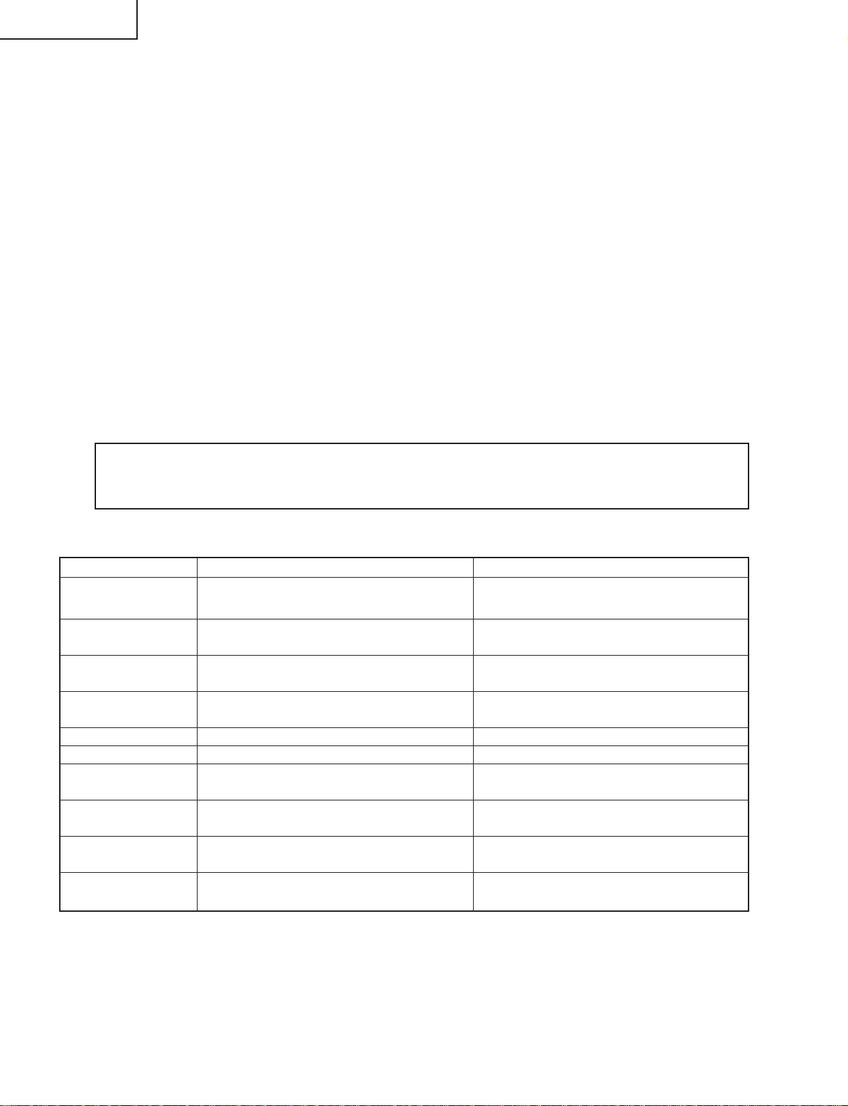
First layer Page Item Setting range Initial value
Table of contents 1 GRAYLEVEL 0 ~ 255 25
COM BIAS 0 ~ 255 126
VLS BIAS 0 ~ 255 23
L ERR RESET Totally clear 0
LCD 1 MODE 50Hz,60Hz,PC 60Hz
PWM CTRL 0 ~ 7 7
PWM FREQ 0 ~ 4095 1289
PWM DUTY1 0 ~ 4095 0
PWM DUTY2 0 ~ 4095 0
PHASEDIF 0 ~ 255 0
PCLK1 0 ~ 3 0
PCLK2 0 ~ 7 0
2 MODE 50Hz,60Hz,PC 60Hz
OS SW 0 ~ 1 0
OS D1 0 ~ 255 110
OS D2 0 ~ 255 123
OS D3 0 ~ 255 135
OS D4 0 ~ 255 135
OS D5 0 ~ 255 167
OS D6 0 ~ 255 174
OS D7 0 ~ 255 179
3 OPC 0 0 ~ 85 0
OPC 1 0 ~ 85 11
OPC 2 0 ~ 85 21
OPC 3 0 ~ 85 30
OPC 4 0 ~ 85 38
OPC 5 0 ~ 85 45
OPC 6 0 ~ 85 51
OPC 7 0 ~ 85 56
OPC 8 0 ~ 85 61
4 OPC 9 0 ~ 85 66
OPC 10 0 ~ 85 70
OPC 11 0 ~ 85 73
OPC 12 0 ~ 85 76
OPC 13 0 ~ 85 79
OPC 14 0 ~ 85 81
OPC 15 0 ~ 85 83
OPC 16 0 ~ 85 85
5 VH 0 0 ~ 1023 124
VL 0 0 ~ 1023 904
VH 1 0 ~ 1023 359
VL 1 0 ~ 1023 598
VH 20 0 ~ 1023 397
VL 20 0 ~ 1023 579
VH 47 0 ~ 1023 416
VL 47 0 ~ 1023 551
6 VH 63 0 ~ 1023 454
VL 63 0 ~ 1023 517
VH 95 0 ~ 1023 485
VL 95 0 ~ 1023 486
VH 127 0 ~ 1023 538
VL 127 0 ~ 1023 538
VH 191 0 ~ 1023 1022
VL 191 0 ~ 1023 122
LC-26GA4D
LC-26GA4U
35
Page 36

LC-26GA4D
LC-26GA4U
<Power supply>
TROUBLE SHOOTING TABLE
No power supply (Front LED is off) or no power-up (Front LED does not change from red to green)
Is power cable properly connected to the main unit?
YES
Is F701 normal?
YES
Is BU+5V line (pin (16) of CN706, pin (8) of CN707 and pin
(4) of CN708) normal?
YES
Are the wire harness, FFC, etc. in the set connected properly?
YES
Is the voltage (approx. 380V) available at C709/C710 when the
power is turned on?
YES
Is the voltage available in 15V line immediately after the power is
turned on?
YES
Is each DC/DC converter output (IC707-711 and IC716) normal?
NO
NO
NO
NO
NO
NO
NO
Connect the power cable properly, and turn on the power.
Replace F701, and turn on the power. If the fuse is still blown,
replace VA701, VA702, D701, D702, L703, Q701, Q702 and
IC701. Then repeat the check.
Is there any defective part or short-circuit in BU+5V line?
YES
Check the BU+5V line power circuits (F703,
D722, IC703, T703, PC702, D761, and IC715).
Remove the defective part or short-circuit, and repeat the check.
Reconnect the wire harness, FFC, etc. in the set properly, and
repeat the check.
Check the 380V line power circuits (L703, IC701, Q701-5, D706
and TH 701).
Check the 15V line power circuits (T701, T702, F704, Q706-14,
PC703-4, D708-17, IC702, L710, Q733-6, D735-6, D780 and
IC706).
Check each DC/DC converter and line (IC707-11 and IC716).
Replace if necessary.
NO
• Power switch: Top panel
(Main) Power (DC cutoff: Detected by microprocessor)
[Scheme of power supply system]
Relay
[(Main) Power OFF sequence]
1) (Main) Power OFF (DC switch)
2) (Main) Power shutoff is detected by the monitor microprocessor port.
3) Standby request (power cord) is sent to Seine from the microprocessor.
4) Seine shutdown process
5) Reception of shutdown permission from Seine
6) Monitor microcomputer turns off the relay to enter the standby mode.
Seine
Main
Monitor microprocessorBackup
(Main) Power
36
Page 37

<Signals>
LC-26GA4D
LC-26GA4U
TROUBLE SHOOTING TABLE (Continued)
No Sound (1)
No headphone audio output
YES
Check between pins (26), (27) (OUT L/R) of IC2702 and HP
AMP (IC2502), audio mute (Q2501) and headphone terminal
(J2402), as well as their peripheral circuits.
YES
Check the headphone plug circuit.
Check between headphone (pin (4) of J2402) and pin (7) of
IC1102.
No audio output during UHF/VHF reception
YES
Is the volume icon set on speaker when volume key is operated?
YES
No Sound (2)
NO
No monitor audio output
YES
Check if monitor audio output is set to "variable" or if headphone
is connected.
YES
Is there normal audio output in IC2501 (Multi Sound Processor)?
Check pins (37) and (36) (SC1 OUT L/R) of IC2501.
YES
Check between pins (37), (36) (SC1 OUT L/R) of IC2501 (Multi
Sound Processor) and pins (5), (3) of IC2504 (EQ AMP).
Is there normal audio output for each?
YES
Check between pins (5), (3) of IC2504 (EQ AMP) and pins (6),
(3) of monitor audio output terminal (J1105), namely Q1102 and
Q1103.
If monitor output is set to "variable" in the menu, change the
setting to "fixed".
Is there normal signal input at pins (67) (SOUND IF1) and (69)
(SOUND IF2) of IC2501 (Multi Sound Processor)?
YES
Are there normal audio outputs from pins (34) and (33) (SC2
OUT L/R) of IC2501 toward pins (32) and (33) of IC2702 (DIR)?
YES
Are there normal audio outputs at pins (28) and (29) (A-OUT
L/R) of IC2702?
YES
Are there normal audio outputs from pins (28) and (29) of IC2702
toward pins (13) and (15) of P3801 (1-bit amplifier input)?
YES
Are the 1-bit amplifier signals supplied to each pin of P8003?
YES
Is relay switching done normally from AV PWB P6003 to RY6001
(speaker switch)?
NO
NO
NO
NO
NO
Is there normal SIF output from tuner? (Pin (7) of TU1101 and
TU1102)
YES
Check TU1101/1102 (U/V tuner) and the peripheral circuits.
Check between pins (34), (33) (SC2 OUT L/R) of IC2501 and
pins (32), (33) of IC2702 DIR).
Are there normal I/O signals of LRCK, BICK, SDTO and SDTI
between IC2702 and IC2700 (DSP)?
YES
Check IC2702 and the peripheral circuits.
Check the circuits from pins (28) and (29) of IC2702 to pins (13)
and (15) of P3801 (1-bit amplifier input), (IC3802 and Q3805-6).
Check 1-bit amplifier and the peripheral circuits.
37
Page 38

LC-26GA4D
YES
YES
YES
YES
YES
YES
YES
YES
NO
NO
NO
NO
YES
YES
YES
YES
YES
NO
NO
NO
NO
NO
NO
NO
NO
<Signals>
No Picture (1)<Composite video signal> input
External input in trouble <INPUT 1>
Is INPUT 1 selected in the input select menu
screen?
Is composite video signal detection
functioning normally? Check between pin
(11) of J1101 and pin (9) of IC1102.
Check between pin (8) of J1101 and pin (65)
of IC3800.
Select Video 1 and the input signal in the input
select menu screen.
If signal name is gray and not selectable in
the menu screen
Is composite video signal detection
functioning normally? Check between pin
(10) of J1101 and pin (11) of IC1102.
Check between pin (9) of J1101 and pin (71)
of IC3800.
Check IC3800 (AV SWITCH) and the
peripheral circuits.
Select INPUT 2 and the input signal in the
input select menu screen.
If signal name is gray and not selectable in
the menu screen
Is there video signal input at pin (65) of
IC3800 (AV SWITCH)?
Is there video signal input at pin (85) of
IC400 (MAIN VIDEO CHROMA)?
Are there digital video signal outputs at pins
(43), (44), (46)~(49), (54), (55) and (58) of
IC400?
Are there digital video signal inputs at pins (53), (54), (57)~(60), (51), (52) (RE0-7), pins(63)~(68), (61), (62) (GE0-7), pin
s (73)~(78), (69),
(70) (BE0-7), pins (81)~(86), (79), (80) (RO0-7), pins (91)~(96), (89), (90) (GO0-7), pins (99), (100), (1), (2), (5), (6), (97
), (98) (BO0-7), and
pins (7)~(10) (HSYNC, VSYNC, DE, CLKIN) of IC3201 (LVDS TRANSMITTER)?
Are there digital video signal outputs at pins (49)(TA1
–), (48)(TA1+), (47)(TB1
–), (46)(TB1+), (44)(TC1
–), (43)(TC1+),(41)(TCLK
–),
(42)(TCLK+), (40)(TD1
–), (39)(TD1+), (37)(TA2
–), (36)(TA2+), (35)(TB2
–), (34)(TB2+), (32)(TC2
–), (31)(TC2+), (30)(TCLK2
–),(29)(TCLK2+),
(28)(TD2–), and (27)(TD2+) of IC3201?
Is INPUT 2 selected in the input select menu
screen?
Is there video signal input at pin (71) of
IC3800 (AV SWITCH)?
Are there MAIN VIDEO signal output at pin (60) of IC3800 and SUB VIDEO signal output at pin (56)?
Are there video signal input at pin (2) of IC401 (MAIN L.P.F.) and at pin (2) of IC501 (SUB L.P.F.)?
External input in trouble <INPUT 2>
Check between IC3800 and IC401/IC501.
<MAIN SYSTEM> <SUB SYSTEM>
Check between IC401 and IC400.
Is there video signal input at pin (85) of
IC500 (SUB VIDEO CHROMA)?
Check between IC501 and IC500.
Check IC 400 (MAIN VIDEO CHROMA)
and the peripheral circuits.
Are there digital video signal outputs at pins
(43), (44), (46)~(49), (54), (55) and (58) of
IC500?
Check IC500 (SUB VIDEO CHROMA) and
the peripheral circuits.
Replace the main PWB, or check between
IC400/IC500 and IC3201.
Check IC3201 (LVDS TRANSMITTER) and
the peripheral circuits.
Check the LCD CONTROL PWB.
LC-26GA4U
TROUBLE SHOOTING TABLE (Continued)
38
Page 39

YES
YES
YES
YES
YES
YES
YES
NO
NO
NO
NO
NO
NO
NO
NO
YES
YES
YES
YES
YES
YES
NO
NO
NO
NO
NO
NO
YES
NO
NO
<SUB SYSTEM>
External input in trouble <INPUT 3>
Is INPUT 3 selected in the input select
menu screen?
Is there signal input at each input pin of
IC3800 (AV SWITCH)?
<Composite video signal input>
Is there signal input at pin (3)?
<S-video signal input>
Are there Y-signal input at pin (5) and C-
signal input at pin (7)?
Select INPUT 3 and the input signal in the
input select menu screen.
If signal name is gray and not selectable in
the menu screen
Is composite video signal detection
functioning normally? Check between pin
(11) of J1106 and pin (12) of IC1102.
Is S-video signal detection functioning
normally? Check between pin (6) of
SC1105 and pin (6) of IC3800.
Check between pin (8) of J1106 and pin
(3) of IC3800.
Check between pins (3), (4) of SC1105
and pins (5), (7) of IC3800.
<Composite video signal / S-video signal> input
<Composite video signal input> Are there MAIN VIDEO signal output at pin (60) of IC3800 and SUB VIDEO signal output at pin (56)
?
<S-video signal input> Are there MAIN Y-signal output at pin (60) and MAIN C-signal output at pin (59) of IC3800, and SUB Y-sig
nal output at pin (56) and SUB C-signal output at pin (55)?
<Composite video signal input> Are there video signal input at pin (2) of IC401 (MAIN L.P.F.) and at pin (2) of IC501 (SUB L.P.
F.)?
<S-video signal input> Are there MAIN Y-signal input at pin (2) and MAIN C-signal input at pin (6) of IC401, and SUB Y-signal i
nput at pin (2) and SUB C-signal input at pin (6) of IC501?
<MAIN SYSTEM>
Check between IC401 and IC400.
<Composite video signal input>
Is there video signal input at pin (85) of
IC400 (MAIN VIDEO CHROMA)?
<S-video signal input>
Are there MAIN Y-signal input at pin (85)
and MAIN C-signal input at pin (90) of
IC400 (MAIN VIDEO CHROMA)?
Are there digital video signal outputs at pins (43),
(44), (46)~(49), (54), (55) and (58) of IC400?
Check IC400 (MAIN VIDEO CHROMA) and
the peripheral circuits.
No Picture (2) No Picture (3)
No TV (U/V) picture output
Is there video signal output at output pin
(17) of the tuner (TU1101/1102)?
Are there video signal inputs at pins (7) and
(1) of IC1103 (LEVEL ADJ)?
Is each tuner video input to IC3800 (AV
SWITCH) normal?
Pin (17) (MAIN TUNER IN) of IC3800
Pin (19) (SUB TUNER IN) of IC3800
Check the tuner (TU1101/1102) and its
peripheral circuits. Replace if necessary.
Are there inputs of level adjustment control
signals at pins (6) and (2) of IC1103
(LEVEL ADJ) from pins (1) and (2) of IC1105?
Check IC1105 (CONTROL) and the peripheral
circuits. Replace if necessary.
Check IC3800 (AV SWITCH) and the
peripheral circuits.
Check between IC3800 and IC401/IC501.
Are there digital video signal inputs at pins (53), (54), (57)~(60), (51), (52) (RE0-7), pins(63)~(68), (61), (62) (GE0-7), pin
s (73)~(78), (69), (70) (BE0-7), pins
(81)~(86), (79), (80) (RO0-7), pins (91)~(96), (89), (90) (GO0-7), pins (99), (100), (1), (2), (5), (6), (97), (98) (BO0-7), an
d pins (7)~(10) (HSYNC, VSYNC, DE,
CLKIN) of IC3201 (LVDS TRANSMITTER)?
Are there digital video signal outputs at pins (49)(TA1
–), (48)(TA1+), (47)(TB1
–), (46)(TB1+), (44)(TC1
–), (43)(TC1+), (41)(TCLK
–), (42)(TCLK+), (40)(TD1
–),
(39)(TD1+), (37)(TA2
–), (36)(TA2+), (35)(TB2
–), (34)(TB2+), (32)(TC2
–), (31)(TC2+), (30)(TCLK2
–),(29)(TCLK2+), (28)(TD2
–), and (27)(TD2+) of IC3201?
<Composite video signal input>
Is there video signal input at pin (85) of
IC500 (SUB VIDEO CHROMA)?
<S-video signal input>
Are there SUB Y-signal input at pin (85)
and SUB C-signal input at pin (90) of
IC500 (SUB VIDEO CHROMA)?
Check between IC501 and IC500.
Are there digital video signal outputs at pins (43),
(44), (46)~(49), (54), (55) and (58) ofIC500?
Check IC500 (SUB VIDEO CHROMA) and
the peripheral circuits.
Replace the main PWB, or check between
IC400/IC500 and IC3201.
Check IC3201 (LVDS TRANSMITTER) and
the peripheral circuits.
Check the LCD CONTROL PWB.
TROUBLE SHOOTING TABLE (Continued)
LC-26GA4D
LC-26GA4U
39
Page 40

LC-26GA4D
YES
YES
YES
YES
YES
YES
YES
NO
NO
NO
NO
NO
NO
YES
YES
YES
YES
YES
NO
NO
NO
NO
NO
NO
YES
NO
NO
<Component video signal> input No Picture (4)
External input in trouble <INPUT 1>
Is INPUT 1 selected in the input select
menu screen?
Select INPUT 1 and the input signal in the
input select menu screen.
If signal name is gray and not selectable in
the menu screen
Is component video signal detection
functioning normally? Check between pin
(11) of J1107 and pin (32) of IC1001.
Are there signal inputs at pins (53), (55) and
(57) (Y, PB, PR) of IC3801 (COMPONENT
SWITCH)?
Check between J1107 and each input pin
of IC3801.
Check IC3700 (ADC) and the peripheral
circuits.
Are there MAIN VIDEO signal outputs at pins (50), (48), (46) (Y, PB, PR) of IC3801, PASS VIDEO signal outputs at pins (38), (36
), (34) (Y, PB, PR), and SUB
VIDEO signal outputs at pins (44), (42) and (40) (Y, PB, PR)?
SYSTEM (Single) <1 screen: 480i/480p/1080i/720p, Twin screens: 480p/1080i/720p> Are there PASS VIDEO signal inputs at pins (1),
(5) and (25) (Y, CB, CR) of IC3703 (L.P.F.)?
SYSTEM (Twin) <2 screens: 480i> Are there MAIN/SUB VIDEO signal inputs at pins (8), (10), (13) (Y, PB, PR) of IC401 (MAIN L.P.F
.) and IC501 (SUB L.P.F.)
External input in trouble <INPUT 2>
Is INPUT 2 selected in the input select
menu screen?
Select INPUT 2 and the input signal in the
input select menu screen.
If signal name is gray and not selectable in
the menu screen
Is component video signal detection
functioning normally? Check between pin
(10) of J1107 and pin (76) of IC3800.
Are there signal inputs at pins (5), (7) and (9)
(Y, PB, PR) of IC3801 (COMPONENT
SWITCH)?
Check between J1107 and each input pin
of IC3801.
Check IC3801 (COMPONENT SWITCH)
and the peripheral circuits.
Check between IC3801 and IC3703, and
between IC3801 and IC401/IC501.
SYSTEM (1) SYSTEM (2)
Are there signal inputs at pins (5), (13) and
(20) (R, G, B) of IC3700 (ADC)?
Is there signal output of RA0-7, RB0-7,
BA0-7, BB0-7, GA0-7, etc. from each
output pin of IC3700?
Check between IC3703 and IC3700.
<MAIN SYSTEM>
Are there signal inputs at pins (85), (92) and (94)
(Y, PB, PR) of IC400 (MAIN VIDEO CHROMA)?
<SUB SYSTEM>
Are there signal inputs at pins (85), (92) and
(94) (Y, PB, PR) of IC500 (SUB VIDEO
CHROMA)?
Check between IC401 and IC400.
Check between IC501 and IC500.
Check IC500 (SUB VIDEO CHROMA) and
the peripheral circuits.
Check IC 400 (MAIN VIDEO CHROMA)
and the peripheral circuits.
Replace the main PWB, or check between
IC400/IC500 and IC3201.
Check IC3201 (LVDS TRANSMITTER) and
the peripheral circuits.
<MAIN SYSTEM>
Are there digital video signal outputs at pins (43),
(44), (46)~(49), (54), (55) and (58) of IC400?
<SUB SYSTEM>
Are there digital video signal outputs at pins (43),
(44), (46)~(49), (54), (55) and (58) of IC500?
Are there digital video signal outputs at pins (49)(TA1
–), (48)(TA1+), (47)(TB1
–), (46)(TB1+), (44)(TC1
–), (43)(TC1+), (41)(TCLK
–), (42)(TCLK+), (40)(TD1
–),
(39)(TD1+), (37)(TA2
–), (36)(TA2+), (35)(TB2
–), (34)(TB2+), (32)(TC2
–), (31)(TC2+), (30)(TCLK2
–),(29)(TCLK2+), (28)(TD2
–), and (27)(TD2+) of IC3201?
Are there digital video signal inputs at pins (53), (54), (57)~(60), (51), (52) (RE0-7), pins(63)~(68), (61), (62) (GE0-7), pin
s (73)~(78), (69), (70) (BE0-7), pins
(81)~(86), (79), (80) (RO0-7), pins (91)~(96), (89), (90) (GO0-7), pins (99), (100), (1), (2), (5), (6), (97), (98) (BO0-7), an
d pins (7)~(10) (HSYNC, VSYNC, DE,
CLKIN) of IC3201 (LVDS TRANSMITTER)?
Check the LCD CONTROL PWB.
LC-26GA4U
TROUBLE SHOOTING TABLE (Continued)
40
Page 41

TROUBLE SHOOTING TABLE (Continued)
DVI Input (Digital PC mode)
Are there Rx0, 1, 2 and C signal
inputs to IC1900?
YES
NO YES
Are IC1915 data accessed by I
when connected to PC?
NO
2
C
LC-26GA4D
LC-26GA4U
Check PC settings.
Are there Hsync, Vsync and RGB
DAC signal outputs from IC1900?
YES
Are there RGB, Hsync and Vsync
signal outputs from MD connector?
YES
Are there RGB, Hsync and Vsync
signal inputs to the main PWB
IC3700 and IC3701?
YES
NO
NO
NO
Are outputs at pins (12) and (14) of
IC1917 both (H, H)?
NO
Do pins (12) and (14) become (L, L)
when analog AV mode is entered?
NO
Check ME connector I2C signal line.
Check IC1900 and its
peripheral circuits.
Check IC1901, IC1903 and
their peripheral circuits.
Check MD harness for
disconnection.
YES
YES
Check IC1915 and its
peripheral circuits.
Check IC1917 and its
peripheral circuits.
Check IC3700, IC3701 and their
peripheral circuits.
41
Page 42

LC-26GA4D
LC-26GA4U
TROUBLE SHOOTING TABLE (Continued)
DVI Input (Analog PC mode)
Are there RGB signal inputs at pins
(25), (26) and (27), and Hsync/Vsync
signal inputs at pins (28) and (8) from
DVI connector?
YES
NO YES
Are IC1915 data accessed by I
when connected to PC?
NO
Are outputs at pins (12) and (14) of
IC1917 both (H, L)?
NO
2
C
YES
Check PC settings.
Check IC1915 and its
peripheral circuits.
Are there Vsync and Hsync signal
outputs at pins (4) and (6) of IC1904?
YES
Are there RGB, Hsync and Vsync
signal outputs from MD connector?
YES
Are there RGB, Hsync and Vsync
signal inputs to IC3700 and IC3701
of the main PWB?
YES
Check IC3700, IC3701 and their
peripheral circuits.
NO
NO
NO
Do pins (12) and (14) become (L, H)
when digital AV mode is entered?
NO
Check ME connector I2C signal line.
Check IC1904 and its
peripheral circuits.
Check IC1901, IC1903 and
their peripheral circuits.
Check MD harness for
disconnection.
YES
Check IC1917 and its
peripheral circuits.
42
Page 43

TROUBLE SHOOTING TABLE (Continued)
DVI Input (Digital AV mode)
Are there Rx0, 1, 2 and C signal
inputs to IC1900?
YES
NO YES
Are IC1911 data accessed by I
when connected to PC?
NO
2
C
LC-26GA4D
LC-26GA4U
Check PC settings.
Are there Hsync, Vsync and RGB
DAC signal outputs from IC1900?
YES
Are there RGB, Hsync and Vsync
signal outputs from MD connector?
YES
Are there RGB, Hsync and Vsync
signal inputs to the main PWB
IC3700 and IC3701?
YES
NO
NO
NO
Are outputs at pins (12) and (14) of
IC1917 both (L, H)?
NO
Do pins (12) and (14) become (H, L)
when analog PC mode is entered?
NO
Check ME connector I2C signal line.
Check IC1900 and its
peripheral circuits.
Check IC1901, IC1903 and
their peripheral circuits.
Check MD harness for
disconnection.
YES
YES
Check IC1911 and its
peripheral circuits.
Check IC1917 and its
peripheral circuits.
Check IC3700, IC3701 and their
peripheral circuits.
43
Page 44

LC-26GA4D
LC-26GA4U
TROUBLE SHOOTING TABLE (Continued)
DVI Input (Analog AV mode)
Are there RGB signal inputs at pins
(25), (26) and (27), and Hsync/Vsync
signal inputs at pins (8) and (28) from
DVI connector?
YES
NO YES
Are IC1911 data accessed by I
when connected to PC?
NO
Are outputs at pins (12) and (14) of
IC1917 both (L, L)?
NO
2
C
YES
Check PC settings.
Check IC1915 and its
peripheral circuits.
Are there Vsync and Hsync signal
outputs at pins (4) and (6) of IC1904?
YES
Are there RGB, Hsync and Vsync
signal outputs from MD connector?
YES
Are there RGB, Hsync and Vsync
signal inputs to IC3700 and IC3701
of the main PWB?
YES
Check IC3700, IC3701 and their
peripheral circuits.
NO
NO
NO
Do pins (12) and (14) become (H, H)
when digital PC mode is entered?
NO
Check ME connector I2C signal line.
Check IC1904 and its
peripheral circuits.
Check IC1901, IC1903 and
their peripheral circuits.
Check MD harness for
disconnection.
YES
Check IC1917 and its
peripheral circuits.
44
Page 45

TROUBLE SHOOTING TABLE (Continued)
Are there signal inputs from HDMI
(SC1901) connector to each input pin of
RX0±} (pins (86) and (87)), RX1±} (pins
(91) and (92)), RX2±} (pins (96) and (97))
and RXC±} (pins (83) and (84)) of IC1912
(HDMI Receiver)?
YES
NO
No HDMI input picture
Is IC1913 (E
read out DDC
HDMI equipment is connected?
Check IC1913 (CONTROL) and the
peripheral circuits.
Is there HDMI RST signal output at
output pin (6) of IC1914 (CONTROL)?
Check IC1914 (CONTROL) and the
peripheral circuits.
2
PROM) accessed by
I2C
CLOCK/DATA when
NO
YES
NO
I2C
to
YES
YES
LC-26GA4D
LC-26GA4U
Check HDMI equipment settings.
Check IC1912 and the peripheral
circuits.
Are there HDMI Y/Pb/Pr and HDMI H/V
signal outputs from MF connector?
YES
Are there HDMI Y/Pb/Pr and HDMI H/V
signal inputs to IC3703 (L.P.F.) and
IC3701 (SYNC SELECTOR) of the main
PWB?
YES
Check IC3703, IC3701 and the
peripheral circuits.
YES
YES
Check IC1912 (HDMI Receiver) and the
peripheral circuits.
Check MF harness for disconnection.
45
Page 46

LC-26GA4D
LC-26GA4U
OVERALL WIRING DIAGRAM/CHASSIS LAYOUT
H
G
F
E
D
C
B
A
87109654321
46
Page 47

LC-26GA4D
LC-26GA4U
47
1716 1918151413121110
Page 48

LC-26GA4D
LC-26GA4U
SYSTEM BLOCK DIAGRAM
H
G
F
E
D
C
B
A
87109654321
48
Page 49

LC-26GA4D
LC-26GA4U
49
1716 1918151413121110
Page 50

LC-26GA4D
LC-26GA4U
MAIN BLOCK DIAGRAM
H
G
F
E
D
C
B
A
87109654321
50
Page 51

LC-26GA4D
LC-26GA4U
51
1716 1918151413121110
Page 52

LC-26GA4D
LC-26GA4U
CPU BLOCK DIAGRAM-1/2
H
G
F
E
D
C
B
A
87109654321
52
Page 53

LC-26GA4D
LC-26GA4U
53
1716 1918151413121110
Page 54

LC-26GA4D
W
3
T
e
CS3
W
7
W
5
M
LC-26GA4U
CPU BLOCK DIAGRAM-2/2
H
G
(N0546FJ)
:Power
BU5V
10V
D3V3
1.9V
(N0567FJ)
:PC IF to TMDS
(VHH
TXD
D3V3
RXD
(MLC157DT,
:Th
(7
:S
(N0060CE)
:DebugPORT
TCK, TMS, N_TRST,
F
E
TDI, TDO,N_ASEMDO,
N_ASEBRKAK,N_RESETP
12.288MHz
(CA045WJ)
:CLK-Gen
EXTAL
XTAL
PLL
(PST6001M)
:Reset IC
D
Slow Bus
(N0056CE)
:PROGRAMPORT
IBO_IRQ
H-UDI
CLOCK/PLL
CS[0-1,3-6]
SBADD[0-25],
SBDAT[0-15]
N_INT_I2CA
N_INT_I2CB
N_CPLD_INT[0-1]
IRQ
N_WAIT
N_RD, N_BS
TXD2
RXD2
(A817WJ)
:SH-7706 CPU
Slow Bus
CKIO
N_WE1/N_DQMLU
N_WE0/N_DQMLL,
UART
N_WE3/N_DQMUU
N_WE2/N_DQMUL,
N_WE1/N_DQMLU
C
N_WAIT
PM_REQ
N_RD, N_BS
CKIO
SBADD[1-8,19-25], SBDAT[0-15]
CS[0,2,4-6]
N_WE0/N_DQMLL,
N_WE1/N_DQMLU
B
(A948WJ)
:CPLD
N_SRESET
MAIN_RDY
N_CPLD_INT[0-2]
TCK,TDO,TMS,TDI
N_CS_FLASH0,
N_CS_FLASH1
N_RESET_FLASH
FL_VPP0
N_RD_CPLD,
N_WE0_CPLD
N_RESETP
CBOOT, N_EXT_BOOTS, MAIN_INT[0-1]
N_MAIN_RST
N_MAIN_CE[0-1]
N_CS_I2CA,N_CS_I2CB, N_RESET_I2CA,N_RESET_I2CB
N_RESET_SD,N_CS_SD
N_SD_INT
SBADD[1-22], SBDAT[0-15]
(LHF64AF3)
:FLASH 8MB
CKIO
N_WE0/N_DQMLL,
SBADD[2-15], SBDAT[0-15]
SBADD[2-15], SBDAT[16-31]
(A985
(A98
:SDRAM
:SDRA
A
87109654321
54
Page 55

TXD
TXD2
CKIO
S
(VHHT1103J44-1)
RXD
(MLC157DT,7WH126FU)
RXD2
:Thermistor
(7WH126FU)
:SW
:SW
TMPOUT
I2CSLC0, I2CSDA0
TXD0
RXD0
I2CSLC1, I2CSDA1
RS_ON
SRESET
UATXD_A
UARXD_A
(MA159WJ)
:Main Bus IF to Main
PM_REQ
I2CSLC1, I2CSDA1
I2CSLC0, I2CSDA0
CBOOT, N_EXT_BOOTS,
N_MAIN_RST
MAIN_INT[0-1]
MAIN_CLK
MAIN_RDY
N_MAIN_CE[0-1]
LC-26GA4D
LC-26GA4U
D3V3
N_MAIN_OE
N_MAIN_WE[0-1]
SBADD[1-25], SBDAT[0-15]
UART
817WJ)
-7706 CPU
Slow Bus
CS3
N_WE3/N_DQMUU
N_WE2/N_DQMUL,
N_WE1/N_DQMLU
N_WE0/N_DQMLL,
SBADD[2-15], SBDAT[0-15]
SBADD[2-15], SBDAT[16-31]
N_RASL
RD/N_WR
I/O (PortA,B)
Reset
CKE
N_CASL
I2CSLC2, I2CSDA2
SD_PWR
(BR24L64F)
:E2PROM
I2CSLC_B, I2CSDA_B
N_INT_I2CA,N_INT_I2CB
I2CSLC_A, I2CSDA_A
(PCA9564)
:Bus to I2C x2
N_RD
SBADD[1-2],
SBDAT[0-7]
CKIO
N_WE0/N_DQMLL
N_RD
SBADD[1-8], SBDAT[0-15]
N_WE0/N_DQMLL
I2CSLC0, I2CSDA0
N_WAIT
N_MAIN_WE1
↔
CKIO
N_RD
N_WE0/N_DQMLL
N_MAIN_WE0
↔
N_WE1/N_DQMLU
(A985WJ)
(A985WJ x2)
:SDRAM 32MB
:SDRAM 32MB
(TC6384AF)
:SD Card Control IC
DAT[0-2],CD,WP
CD/DAT3,CMD,CLK,
(ZA050WJ)
:SD Card Slot
1716 1918151413121110
55
Page 56

LC-26GA4D
LC-26GA4U
AV BLOCK DIAGRAM
H
G
F
E
D
C
B
A
87109654321
56
Page 57

LC-26GA4D
LC-26GA4U
57
1716 1918151413121110
Page 58

LC-26GA4D
LC-26GA4U
POWER BLOCK DIAGRAM-1/2
H
G
F
E
D
C
B
A
87109654321
58
Page 59

LC-26GA4D
LC-26GA4U
59
1716 1918151413121110
Page 60

LC-26GA4D
LC-26GA4U
POWER BLOCK DIAGRAM-2/2
H
G
F
E
D
C
B
A
87109654321
60
Page 61

LC-26GA4D
LC-26GA4U
61
1716 1918151413121110
Page 62

LC-26GA4D
LC-26GA4U
DESCRIPTION OF SCHEMATIC DIAGRAM
VOLTAGE MEASUREMENT CONDITION:
1. Voltages at test points are measured on exclusive
AC adapter or the stable supply voltage of AC 110240V . Signals are fed by a color bar signal generator
for servicing purpose and the above voltages are
measured with a 20k ohm/V tester.
INDICATION OF RESISTOR & CAPACITOR:
RESISTOR
1. The unit of resistance “Ω” is omitted.
(K=kΩ=1000 Ω, M=MΩ).
2. All resistors are ± 5%, unless otherwise noted.
(J= ± 5%, F= ± 1%, D= ± 0.5%)
3. All resistors are 1/16W, unless otherwise noted.
4. All resistors are Carbon type, unless otherwise
noted.
C : Solid
S : Oxide Film T : Special
N : Metal Coating
CAPACITOR
1. All capacitors are µF, unless otherwise noted.
(P=pF=µµF).
2. All capacitors are 50V, unless otherwise noted.
3. All capacitors are Ceramic type, unless otherwise
noted.
(ML): Mylar (TA): Tantalum
(PF): Polypro Film (ST): Styrol
W
: Cement
CAUTION:
This circuit diagram is original one, therefore there may be a
slight difference from yours.
IMPORTANT SAFETY NOTICE:
PARTS MARKED WITH “å” ( ) ARE
IMPORTANT FOR MAINTAINING THE SAFETY OF
THE SET. BE SURE TO REPLACE THESE PARTS
WITH SPECIFIED ONES FOR MAINTAINING THE
SAFETY AND PERFORMANCE OF THE SET.
AVIS DE SECURITE IMPOR TANT:
LES PIECES MARQUEES “å” ( )SONT
IMPORTANTES POUR MAINTENIR LA SECURITE
DE L'APPAREIL.
NE REMPLACER CES PIEDES QUE PAR DES
PIECES DONT LE NUMERO EST SPECIFIE POUR
MAINTENIR LA SECURITE ET PROTEGER LE BON
FONCTIONNEMENT DE L'APPAREIL.
62
Page 63

SCHEMATIC DIAGRAM
Ë
R/C, LED Unit
H
G
F
LC-26GA4D
LC-26GA4U
E
D
C
B
A
654321
63
Page 64

LC-26GA4D
LC-26GA4U
Ë
DVI Unit-1/2
H
G
F
E
D
C
B
A
87109654321
64
Page 65

LC-26GA4D
LC-26GA4U
65
1716 1918151413121110
Page 66

LC-26GA4D
LC-26GA4U
Ë
DVI Unit-2/2
H
G
F
E
D
C
B
A
87109654321
66
Page 67

LC-26GA4D
LC-26GA4U
67
1716 1918151413121110
Page 68

LC-26GA4D
LC-26GA4U
Ë
LCD CONTROL Unit-1/8
H
G
F
E
D
C
B
A
87109654321
68
Page 69

LC-26GA4D
LC-26GA4U
69
1716 1918151413121110
Page 70

LC-26GA4D
LC-26GA4U
Ë
LCD CONTROL Unit-2/8
H
G
F
E
D
C
B
A
87109654321
70
Page 71

LC-26GA4D
LC-26GA4U
71
1716 1918151413121110
Page 72

LC-26GA4D
LC-26GA4U
Ë
LCD CONTROL Unit-3/8
H
G
F
E
D
C
B
A
87109654321
72
Page 73

LC-26GA4D
LC-26GA4U
73
1716 1918151413121110
Page 74

LC-26GA4D
LC-26GA4U
Ë
LCD CONTROL Unit-4/8
H
G
F
E
D
C
B
A
87109654321
74
Page 75

LC-26GA4D
LC-26GA4U
75
1716 1918151413121110
Page 76

LC-26GA4D
LC-26GA4U
Ë
LCD CONTROL Unit-5/8
H
G
F
E
D
C
B
A
87109654321
76
Page 77

LC-26GA4D
LC-26GA4U
77
1716 1918151413121110
Page 78

LC-26GA4D
LC-26GA4U
Ë
LCD CONTROL Unit-6/8
H
G
F
E
D
C
B
A
87109654321
78
Page 79

LC-26GA4D
LC-26GA4U
79
1716 1918151413121110
Page 80

LC-26GA4D
LC-26GA4U
Ë
LCD CONTROL Unit-7/8
H
G
F
E
D
C
B
A
87109654321
80
Page 81

LC-26GA4D
LC-26GA4U
81
1716 1918151413121110
Page 82

LC-26GA4D
LC-26GA4U
Ë
LCD CONTROL Unit-8/8
H
G
F
E
D
C
B
A
87109654321
82
Page 83

LC-26GA4D
LC-26GA4U
83
1716 1918151413121110
Page 84

LC-26GA4D
LC-26GA4U
Ë
CPU Unit-1/5
H
G
F
E
D
C
B
A
87109654321
84
Page 85

LC-26GA4D
LC-26GA4U
85
1716 1918151413121110
Page 86

LC-26GA4D
LC-26GA4U
Ë
CPU Unit-2/5
H
G
F
E
D
C
B
A
87109654321
86
Page 87

LC-26GA4D
LC-26GA4U
87
1716 1918151413121110
Page 88

LC-26GA4D
LC-26GA4U
Ë
CPU Unit-3/5
H
G
F
E
D
C
B
A
87109654321
88
Page 89

LC-26GA4D
LC-26GA4U
89
1716 1918151413121110
Page 90

LC-26GA4D
LC-26GA4U
Ë
CPU Unit-4/5
H
G
F
E
D
C
B
A
87109654321
90
Page 91

LC-26GA4D
LC-26GA4U
91
1716 1918151413121110
Page 92

LC-26GA4D
LC-26GA4U
Ë
CPU Unit-5/5
H
G
F
E
D
C
B
A
87109654321
92
Page 93

LC-26GA4D
LC-26GA4U
93
1716 1918151413121110
Page 94

LC-26GA4D
LC-26GA4U
Ë
PC CARD Unit-1/4
H
G
F
E
D
C
B
A
87109654321
94
Page 95

LC-26GA4D
LC-26GA4U
95
1716 1918151413121110
Page 96

LC-26GA4D
LC-26GA4U
Ë
PC CARD Unit-2/4
H
G
F
E
D
C
B
A
87109654321
96
Page 97

LC-26GA4D
LC-26GA4U
97
1716 1918151413121110
Page 98

LC-26GA4D
LC-26GA4U
Ë
PC CARD Unit-3/4
H
G
F
E
D
C
B
A
87109654321
98
Page 99

LC-26GA4D
LC-26GA4U
99
1716 1918151413121110
Page 100

LC-26GA4D
LC-26GA4U
Ë
PC CARD Unit-4/4
H
G
F
E
D
C
B
A
87109654321
100
 Loading...