

Page 1

LC-20B6M
LCD COLOUR TELEVISION
ENGLISH
Printed on 100% post-consumer recycled paper.
OPERATION MANUAL
Printed in Japan
TINS-B287WJZZ
04P06-JMM
Page 2

Contents
LC-20B6M
LCD COLOUR TELEVISION
ENGLISH
OPERATION MANUAL
ENGLISH
ENGLISH
Dear SHARP Customer .................................................... 2
Important Safety Precautions ......................................... 2
Trademark ......................................................................... 3
Supplied Accessories ...................................................... 4
Preparation ....................................................................... 5
Installing Batteries in the Remote Control ................... 5
Using Remote Control .................................................5
Power Connection .......................................................6
Antenna Connection ................................................... 6
Listening with Headphones......................................... 6
Part Names of Main Unit .................................................. 7
How to fix the cables ................................................... 8
Part Names of Remote Control ....................................... 9
Basic Operation.............................................................. 10
Turning On and Off the Main Power .......................... 10
Standby .....................................................................10
Switching the Input Modes (AV1/AV2/
COMPONENT/PC/TV)......................................... 10
Sound Volume ........................................................... 11
Changing Channels .................................................. 11
Preset .............................................................................. 12
On-Screen Display Language Selection ................... 12
Presetting the Channels (AUTO) ............................... 12
Presetting the Channels (MANUAL).......................... 13
Channel Setting ......................................................... 14
Clock Setup ............................................................... 14
Selecting Menu Items .................................................... 15
Basic Adjustment Settings............................................ 16
Picture Adjustments .................................................. 16
Colour System (Only AV1 or AV2 Mode) ................... 16
Colour Temperature ................................................... 17
I/P Setup .................................................................... 17
DNR (Digital Noise Reduction).................................. 18
Film Mode.................................................................. 18
Quick Shoot ............................................................... 18
Useful Features .............................................................. 19
Sound Adjustments ................................................... 19
Speech Emphasis ..................................................... 19
Sound Wide ............................................................... 20
PC Sound Select (for PC Mode)................................ 20
Display Mode ............................................................ 21
Te rminal Select ..........................................................21
AV2 In/Out .................................................................22
On-Screen Display Language Setting ...................... 22
Features .................................................................... 23
Wide Mode ................................................................24
Timer Functions ......................................................... 24
NICAM Broadcast Selection .......................................... 25
A2 Stereo Broadcast Selection ..................................... 26
Teletext ............................................................................ 27
Connecting a PC ............................................................ 29
Viewing an Image from a PC..................................... 29
Displaying an Image from a PC ................................ 29
Input Signal (for PC Mode)........................................ 30
Fine Sync. Adjustments (for PC Mode) ..................... 30
Power Management (for PC Mode)........................... 31
PC Compatibility Chart .............................................. 31
Connecting with External Devices ............................... 32
Example of External Devices that can be
Connected .......................................................... 32
Connecting a VCR, DVD Player or a Camcorder
(COMPONENT1/COMPONENT2/AV1/
AV-IN2/PC-IN) .....................................................33
Outputting Video and Audio (Video Output) ............. 34
Troubleshooting ............................................................. 35
Specifications ................................................................. 37
Dimensional Drawings................................................... 38
1
Page 3

Dear SHARP Customer
Thank you for your purchase of the SHARP LCD colour TV product. To ensure safety and many years of trouble-free
operation of your product, please read the Important Safety Precautions carefully before using this product.
Important Safety Precautions
Electricity is used to perform many useful functions, but it can also cause personal injuries and property damage
if improperly handled. This product has been engineered and manufactured with the highest priority on safety.
However, improper use can result in electric shock and/or fire. In order to prevent potential danger, please
observe the following instructions when installing, operating and cleaning the product. To ensure your safety
and prolong the service life of your LCD colour TV product, please read the following precautions carefully
before using the product.
1. Read instructions—All operating instructions must be read and understood before the product is operated.
2. Keep this manual in a safe place—These safety and operating instructions must be kept in a safe place for future
reference.
3. Observe warnings—All warnings on the product and in the instructions must be observed closely.
4. Follow instructions—All operating instructions must be followed.
5. Attachments—Do not use attachments not recommended by the manufacturer. Use of inadequate attachments can
result in accidents.
6. Power source—This product must operate on a power source specified on the specification label. If you are not sure
of the type of power supply used in your home, consult your dealer or local power company.
7. AC cord protection—The AC cords must be routed properly to prevent people from stepping on them or objects
from resting on them. Check the cords at the plugs and product.
8. Overloading—Do not overload AC outlets or extension cords. Overloading can cause fire or electric shock.
9. Entering of objects and liquids—Never insert an object into the product through vents or openings. High voltage
flows in the product, and inserting an object can cause electric shock and/or short internal parts. For the same
reason, do not spill water or liquid on the product.
10. Servicing—Do not attempt to service the product yourself. Removing covers can expose you to high voltage and
other dangerous conditions. Request a qualified service person to perform servicing.
11. Repair—If any of the following conditions occurs, unplug the AC cord from the AC outlet, and request a qualified
service person to perform repairs.
a. When the AC cord or plug is damaged.
b. When a liquid was spilled on the product or when objects have fallen into the product.
c. When the product has been exposed to rain or water.
d. When the product does not operate properly as described in the operating instructions.
Do not touch the controls other than those described in the operating instructions. Improper adjustment of
controls not described in the instructions can cause damage, which often requires extensive adjustment work
by a qualified technician.
e. When the product has been dropped or damaged.
f. When the product displays an abnormal condition. Any noticeable abnormality in the product indicates that
the product needs servicing.
12. Replacement parts—In case the product needs replacement parts, make sure that the service person uses
replacement parts specified by the manufacturer, or those with the same characteristics and performance as the
original parts. Use of unauthorized parts can result in fire, electric shock and/or other danger.
2
13. Safety checks—Upon completion of service or repair work, request the service technician to perform safety checks
to ensure that the product is in proper operating condition.
14. Wall or ceiling mounting—When mounting the product on a wall or ceiling, be sure to install the product according
to the method recommended by the manufacturer.
Page 4
Important Safety Precautions (Continued)
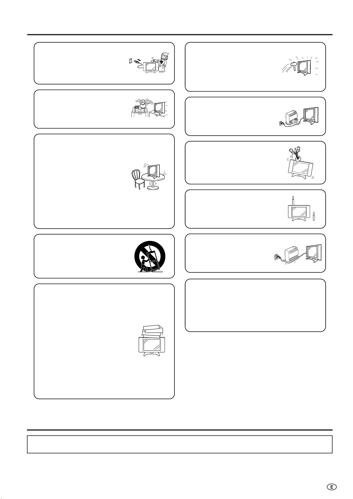
• Cleaning—Unplug the AC cord
from the AC outlet before cleaning
the product. Use a damp cloth to
clean the product. Do not use
liquid cleaners or aerosol
cleaners.
•Water and moisture—Do not use
the product near water, such as
bathtub, washbasin, kitchen sink,
laundry tub, swimming pool and in
a wet basement.
• Stand—Do not place the product
on an unstable cart, stand, tripod
or table. Doing so can cause the
product to fall, resulting in serious
personal injuries as well as
damage to the product. Use only
a cart, stand, tripod, bracket or
table recommended by the
manufacturer or sold with the
product. When mounting the
product on a wall, be sure to
follow the manufacturer’s
instructions. Use only the
mounting hardware recommended
by the manufacturer.
• The LCD panel used in this
product is made of glass.
Therefore, it can break when the
product is dropped or applied
with impact. Be careful not to be
injured by broken glass pieces in
case the LCD panel breaks.
• Heat sources—Keep the product
away from heat sources such as
radiators, heaters, stoves and
other heat-generating products
(including amplifiers).
• Do not place vases or any other
water-filled containers on this
product. The water may spill onto
the product causing fire or electric
shock.
•To prevent fire, never place any
type of candle or naked flames on
the top or near the TV set.
• When relocating the product
placed on a cart, it must be
moved with utmost care. Sudden
stops, excessive force and
uneven floor surface can cause
the product to fall from the cart.
•Ventilation—The vents and other
openings in the cabinet are
designed for ventilation. Do not
cover or block these vents and
openings since insufficient
ventilation can cause overheating
and/or shorten the life of the
product. Do not place the product
on a bed, sofa, rug or other similar
surface, since they can block
ventilation openings. This product
is not designed for built-in
installation; do not place the
product in an enclosed place
such as a bookcase or rack,
unless proper ventilation is
provided or the manufacturer’s
instructions are followed.
•To prevent fire or shock hazard,
do not place the AC power cord
under the TV set or other heavy
items.
The LCD panel is a very high technology product with
2,359,296 thin film transistors, giving you fine picture
details.
Due to the very large number of pixels, a few
non-active pixels may occasionally appear
on the screen as a fixed point of blue, green or red.
This is within product specifications and does not
constitute a fault.
Trademark
• Micronas® VOICE is a Speech Enhancement and Intelligibility Processing technology by Micronas GmbH.
• Micronas is a trademark of Micronas GmbH.
3
Page 5
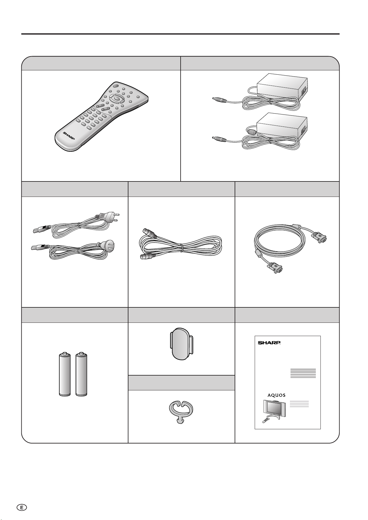
Supplied Accessories
LC-20B6M
Make sure the following accessories are provided with the LCD TV set.
AC cord
Remote control
pages 5 and 9
Antenna cable
AC adapter
*Product shape varies in some countries.
page 6
RGB cable
*Product shape varies in some countries.
“AAA” size batteries (×2)
page 5
page 6
Cable holder
page 8
Cable clamp
page 8
page 29page 6
Operation manual
4
Page 6
Preparation
+
–
+
–
HEADPHONE jack
OPC indicator
POWER indicator
Remote sensor
OPC sensor
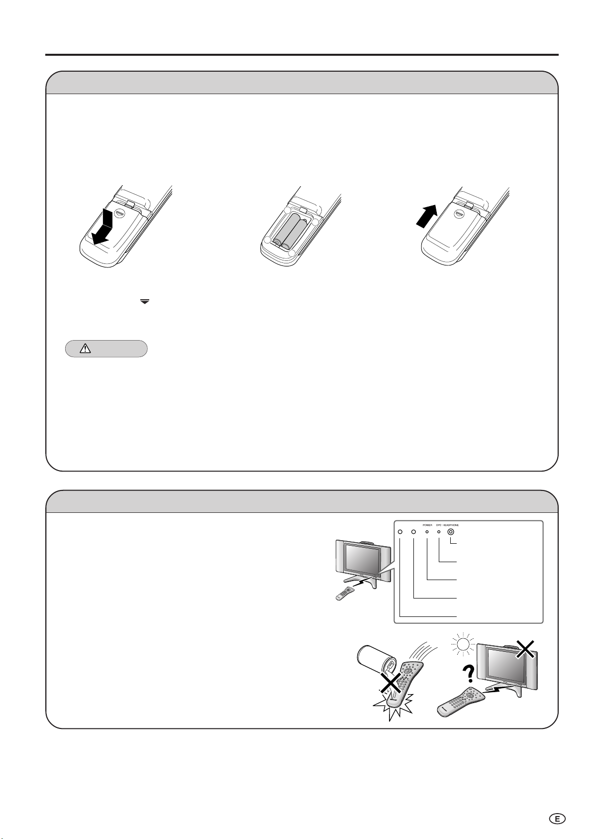
Installing Batteries in the Remote Control
Before using the LCD TV set for the first time, install the two “AAA” size batteries supplied in the remote control. When the
batteries become depleted and the remote control fails to operate, replace the batteries with new “AAA” size batteries.
1 Open the battery cover. 2 Insert two “AAA” size batteries. 3 Close the battery cover.
■ Slide the cover while
pressing the (
) part.
■ Place batteries with their
terminals corresponding to
the (+) and (–) indications in
the battery compartment.
■ Engaging the lower
claw with the remote
control, close the
cover.
Caution!
Precautions regarding batteries
■ Improper use of batteries can result in a leakage of chemicals and/or explosion. Be sure to follow the instructions below.
•Place batteries with their terminals corresponding to the (+) and (–) indications.
•Different types of batteries have different characteristics. Do not mix batteries of different types.
•Do not mix old and new batteries. Mixing old and new batteries can shorten the life of new batteries and/or cause old
batteries to leak chemicals.
•Remove batteries as soon as they are depleted. Chemicals that leak from batteries can cause a rash. If chemical
leakage is found, wipe it off with a cloth.
• The batteries supplied with the LCD TV set may have a shorter operating time due to storage conditions.
• If the remote control is not to be used for an extended period of time, remove the batteries from the remote control.
Using Remote Control
■ Use the remote control by pointing it towards the remote sensor
window of the main unit. Objects between the remote control and
sensor window may prevent proper operation.
Cautions regarding use of remote control
■ Do not apply shock to the remote control. In addition, do not
expose the remote control to liquids, and do not place it in an area
with high humidity.
■ Do not install or place the remote control under direct sunlight. The
heat may cause deformation of the unit.
■ The remote control may not work properly if the remote sensor
window is under direct sunlight or strong lighting. In such a case,
change the angle of the lighting or main unit, or operate the remote
control closer to the remote sensor window.
5
Page 7
Preparation (Continued)
POWER INPUT
DC12V
ANT.
(Antenna terminal)
NOTE
Headphones
NOTE
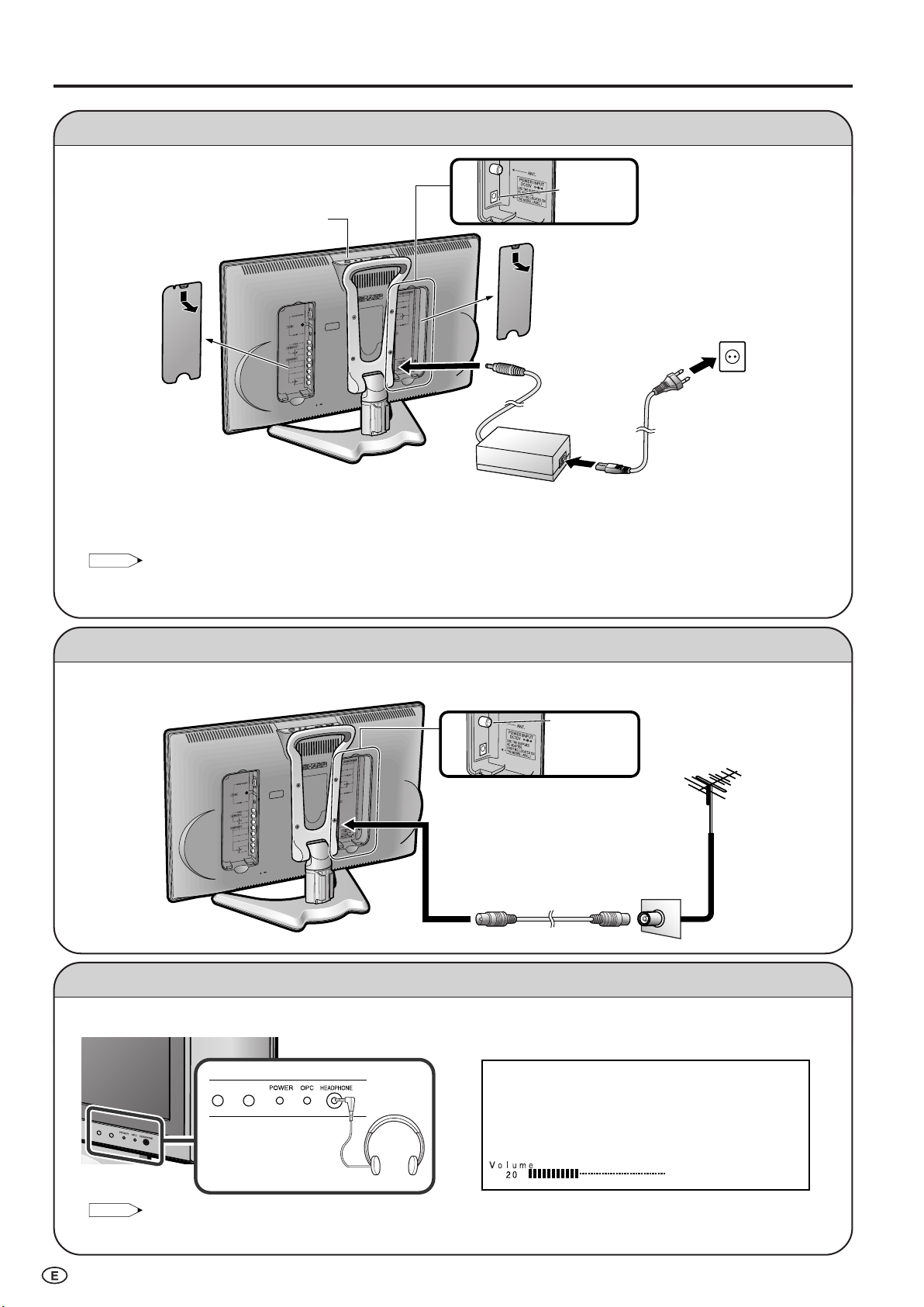
Connect to the DC input terminal of the LCD TV set.
MAIN POWER
Power Connection
Pull down the hook
to open the cover.
■ Using the AC adapter
• Although the AC adapter may become warm during use, this is not a malfunction.
• Do not wrap or cover the AC adapter with a blanket or similar covering. This can cause a malfunction or accident.
• Do not attempt to disassemble or modify the AC adapter. The insides of the AC adapter contain high-voltage components that can
result in the risk of electrical shock.
• Use a commercially available AC plug adapter, if necessary, depending on the design of the wall outlet.
• Always turn the MAIN POWER switch of the LCD TV set to OFF when connecting the AC adapter.
• Unplug the AC adapter from the LCD TV set and power outlet when the LCD TV set is not to be used for a long period of time.
Pull down the hook
to open the cover.
Household
power outlet
To POWER INPUT
terminal
Plug into an AC outlet.
AC adapter
AC cord*
* Product shape varies in some
countries.
Antenna Connection
• Using the supplied antenna cable, connect the room antenna terminal to the antenna terminal on the LCD TV set.
(Refer to the figure below.)
6
Room antenna terminal
Antenna cable (supplied)
To antenna terminal
(75-ohm type)
Listening with Headphones
■ Plug the headphone mini-plug into the HEADPHONE jack located on the front of the LCD TV set.
• Headphones are not included in the supplied accessories.
• No sound is heard from the main unit speakers when a headphone mini-plug is connected into the HEADPHONE jack.
▼ On-screen display
Adjust the sound volume using VOL (+)/(–).
Page 8
MAIN POWER
MENU
INPUT
CH
( )/( )
VOL
( )/( )
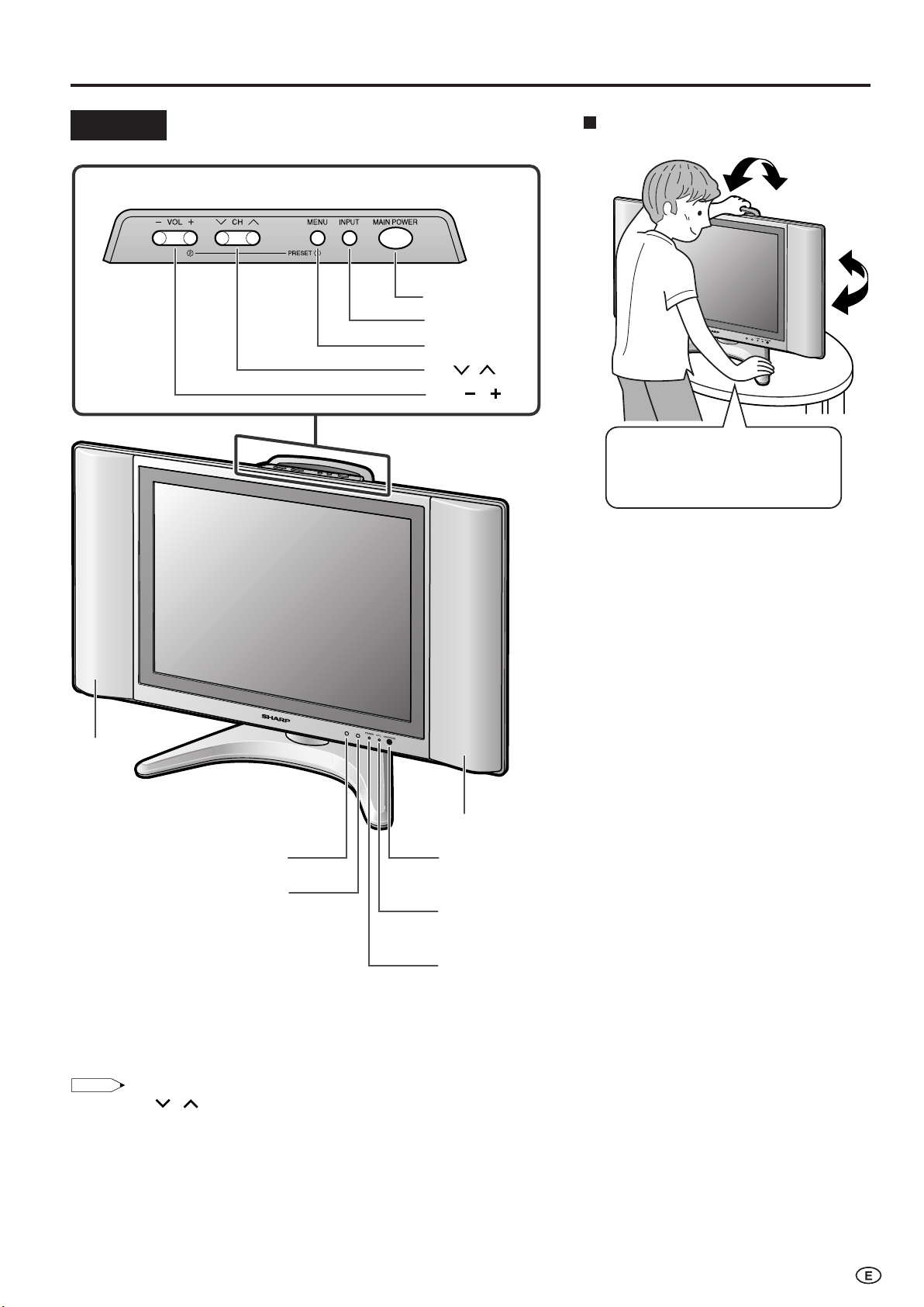
Upper control panel
Part Names of Main Unit
NOTE
Tilt the display by grabbing onto
the carrying handle while securely
holding down the stand with your
other hand.
How to adjust the angle
Controls
Speaker
OPC sensor
Remote sensor
To change the vertical angle of the LCD TV
set, tilt the screen up to 5 degrees forward or
10 degrees backward. The LCD TV set can
also be rotated up to 25 degrees to right and
left. Please adjust the angle so that the LCD
TV set can be watched most comfortably.
Speaker
HEADPHONE jack
Plug the headphone mini-plug into the Headphone jack
located on the front of the LCD TV set. (See page 6.)
OPC indicator (Optical Picture Control)
The Optical Picture Control indicator lights up green when the
“Backlight” is set to “Auto (OPC)”. (See page 23.)
POWER indicator
POWER indicator lights up green when the power is on, and
red when in the standby mode (the indicator will not light
when the main power is off). The indicator lights up orange
when the wake-up timer is set (the indicator will light when in
the standby mode).
• INPUT, CH ( )/( ), VOL (–)/(+) and MENU on the main unit have the same functions as the same buttons on the remote control.
Fundamentally, this operation manual provides a description based on operation using the remote control.
7
Page 9
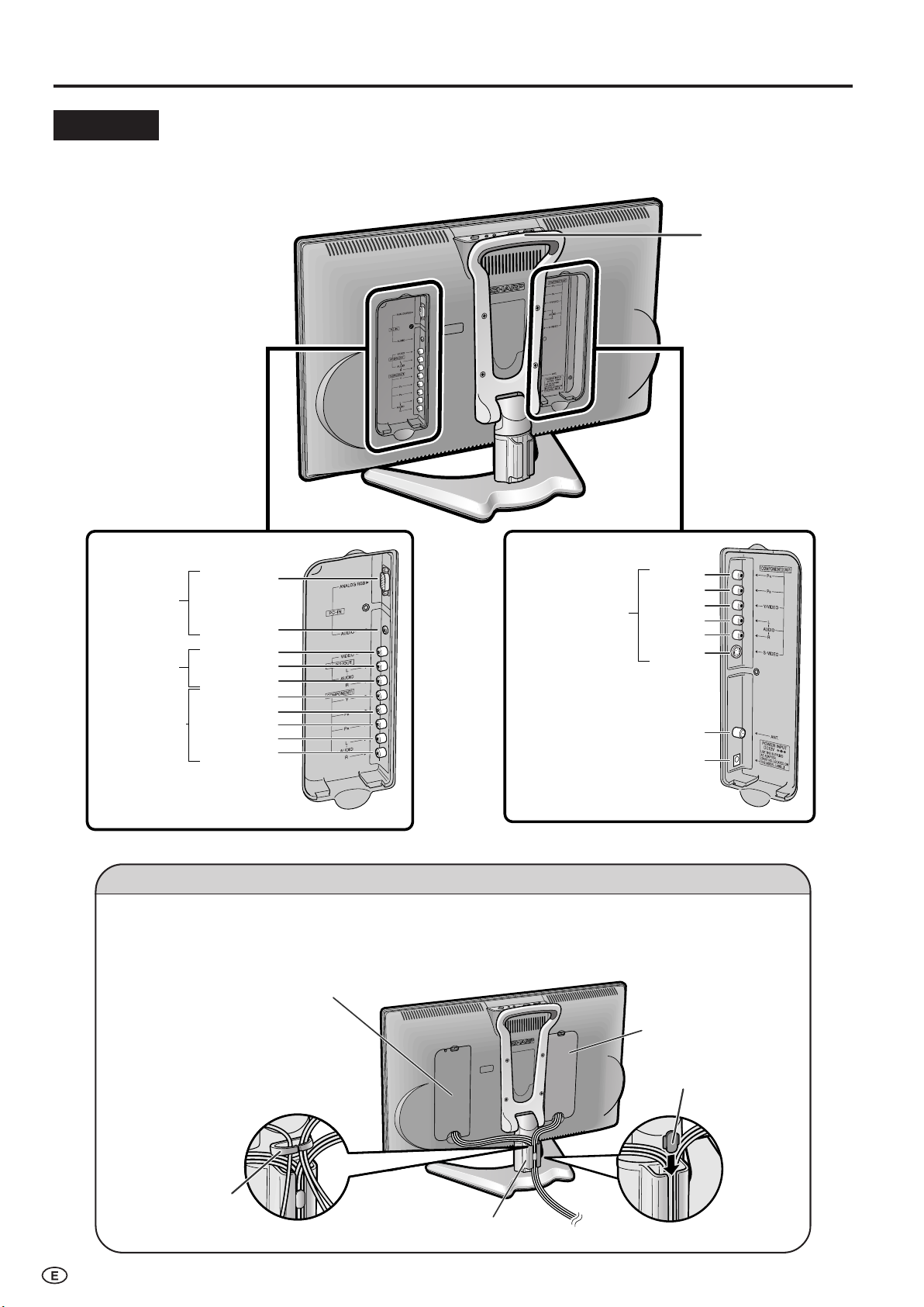
Part Names of Main Unit (Continued)
COMPONENT2/AV1
AUDIO (R)
AUDIO (L)
VIDEO
AV-IN2/OUT
Y
AUDIO (L)
AUDIO (R)
PB
PR
COMPONENT1
ANALOG RGB
AUDIO
PC-IN
ANT. (Antenna terminal)
POWER INPUT (DC12V)
Y/VIDEO
S-VIDEO
AUDIO (L)
AUDIO (R)
PB
PR
Carrying handle
Rear View
Terminal cover
Cable holder
Terminal cover
Support cover
Cable clamp
Terminals
How to fix the cables
Pull the cables connected to each terminal through the holes and close the left and right terminal covers. Push
the cables into the grooves of the support cover. Insert the cable holder (supplied) from above the support cover
and fix the cables.
When the cables cannot be
pushed into the grooves of
the support cover, use the
cable clamp (supplied) to fix
them. The cable clamp can
be attached by pushing it
into the hole on the stand.
8
Page 10
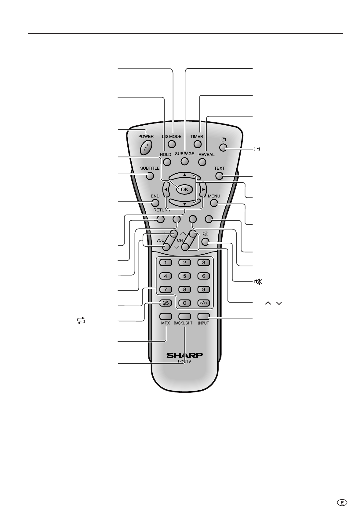
Part Names of Remote Control
SUBTITLE
Displays the Teletext
Subtitle directly.
(P. 28)
OK
(P. 14)
HOLD
Temporarily holds the
current Teletext page.
(P. 28)
DIS.MODE
(P. 21)
(Mute)
Switches the sound on and off.
(P. 11)
Yellow
(P. 27)
Cyan
(P. 27)
Channel Select
(P. 11)
MENU
Displays the TV menu or returns
to normal screen.
(P. 14)
VOL (+)/(
-
)
(P. 11)
(Flashback)
Returns to the previous
channel. (P. 11)
Red, Picture Menu
(P. 16, 27)
Right/Left Selection
(P. 14)
END
Returns to normal screen
in Teletext mode.
(P. 28)
RETURN
Returns to the previous screen.
TEXT
Displays the Teletext mode
screen. (P. 27)
Upwards/Downwards
Selection, Zoom display
function (Teletext mode)
(P. 14, 28)
POWER
(P. 10)
MPX
Switches to the audio
mode. (P. 25)
REVEAL
Displays hidden information
such as solutions to riddles
and puzzles. (P. 28)
(Status Display)
Turns on the status display
when the menu is not
displayed. (P. 24)
SUBPAGE
Displays the Teletext
Subpage directly.
(P. 28)
TIMER
Displays the Timer functions
Menu screen. (P. 24)
INPUT
Switches the input source
between COMPONENT1,
COMPONENT2 (or AV1), AV2,
PC and TV mode. (P. 10)
BACKLIGHT
Selects the brightness and
OPC of the display.
(P. 23)
Green, Sound Menu
(P. 19, 27)
CH ( )/( )
(P. 11)
9
Page 11
NOTE
1
PAL
B/G
Basic Operation
NOTE
COMPONENT1
AV2
PAL
PC
12
PAL
B/G
COMPONENT1 mode
COMPONENT2
AV1
COMPONENT2
mode
AV1 mode
or
AV2 mode
PC mode
TV mode
PAL
48 P
0
48 P
0
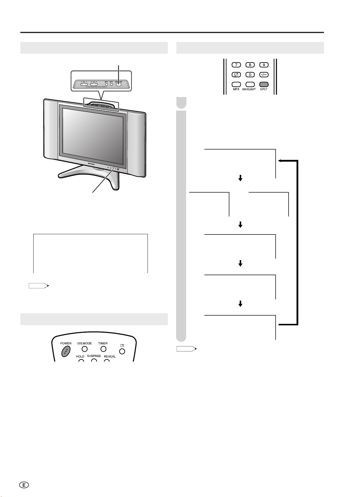
Turning On and Off the Main Power
MAIN POWER
POWER indicator
● Press MAIN POWER. The POWER indicator instantly
changes from red to green and the LCD TV set is turned
on.
On-screen display
Switching the Input Modes (AV1/AV2/COMPONENT/PC/TV)
Turn on the power of the connected video equipment.
1
Press INPUT to select the applicable input source.
2
The screen changes in order of COMPONENT1,
COMPONENT2 or AV1, AV2, PC and TV mode each
time INPUT is pressed.
• The On-screen display disappears after a few seconds.
● To turn off the main power, press MAIN POWER again.
Standby
To turn off the LCD TV
Press POWER. The POWER indicator will turn red.
To turn the LCD TV back on
Press POWER again. The POWER indicator will turn green.
10
• COMPONENT1:
Select this mode when viewing the signals from the video
equipment connected to the COMPONENT1 terminal.
• COMPONENT2:
Select this mode when viewing the signals from the video
equipment connected to the COMPONENT2 terminal. In this
case, set “Terminal select” to “COMPONENT2” (See page 21).
• AV1: Select this mode when viewing the signals from the video
equipment connected to the AV1 terminal. In this case, set
“Terminal select” to “AV1” (See page 21). The S-VIDEO
terminal is additionally provided for the AV1 terminal. If both
S-VIDEO terminal and VIDEO terminal are connected with
cables, the S-VIDEO terminal takes priority.
• AV2: Select this mode when viewing the signals from the video
equipment connected to the AV-IN2 terminal. AV2 mode is
used to adjust the preset settings and In or Out can be
selected. AV2 indication is not displayed when Out is
selected. (For details on setting “AV2 In/Out”, see page 22.)
• PC: Select this mode when viewing the signals from the PC
connected to the PC-IN terminal.
Page 12
Basic Operation (Continued)
NOTE
Volume
50
Volume
10
Volume
10
1
PAL
B/G
--
1-
15
PAL
B/G
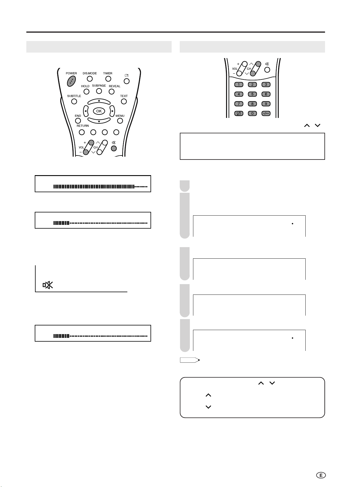
Sound Volume
■ To adjust the volume
● Press VOL (+) to increase the sound volume.
The numerical value increases.
● Press VOL (–) to decrease the sound volume.
The numerical value decreases.
Changing Channels
You can select channels using Channel Select or CH ( )/( ).
•
To handle the increasing number of channels available, this
LCD TV set allows you to select up to 100 positions (Channels
0 to 99). One-digit and two-digit methods of selection can be
used. Follow the procedure shown below to select channels.
■ Using Channel Select
To select a one-digit channel (e.g., Channel 5):
Press 5 of Channel Select.
1
If “5-” is indicated and the picture does not change,
2
press
-/-- to switch over to the 1-digit select mode
and press 5 of Channel Select.
■ To mute the sound
● Press
● Press
ee
e (Mute) to temporarily turn off the sound. The
ee
MUTE mark is displayed on the screen.
ee
e (Mute) or VOL (+)/(–) to turn the sound back to
ee
the previous level. MUTE is automatically cleared when
one of the following buttons are pressed: POWER, VOL
(+)/(–) or
ee
e (Mute).
ee
To select a two-digit channel (e.g., Channel 15):
Press -/-- to set the 2-digit select mode.
1
Press 1 of Channel Select.
2
Press 5 of Channel Select.
3
• Complete this procedure within 4 seconds, otherwise the selection
will not be made.
Changing channels with CH ( )/( ) on the remote
control.
Press CH ( ) and the channels change in the order shown below:
1 → 2 → 3 → . . . → 98 → 99 → 0 → 1 → 2 → 3 → . . .
Press CH ( ) and the channels change in the order shown below:
3 → 2 → 1 → 0 → 99 → 98 → . . . → 3 → 2 → 1 → . . .
■ Using
● Press
● Press
AA
A (Flashback)
AA
AA
A to switch the currently tuned channel to the
AA
previously tuned channel.
AA
A again to switch back to the currently tuned
AA
channel.
11
Page 13

Preset
31, 24
Auto(B/G
)
VHF 1
48.25MHz
NOTE
English
21
Auto(B/G
)
VHF 1
48.25MHz
1
PAL
B/G
NOTE
AUTO MANUAL LANGUAGE NORMAL SCREEN
On-Screen Display Language Selection
MENU on the LCD TV set can also be used to select the
language.
Upper control panel
Press MENU (PRESET-1) on the upper part of the
1
LCD TV set for more than 2 seconds to display the
PRESET mode screen.
Press MENU (PRESET-1) twice to display the
2
LANGUAGE select mode screen.
• Press MENU (PRESET-1) again to change the
PRESET mode as shown below.
Presetting the Channels (AUTO)
Automatically tunes in and presets receivable TV stations.
Make sure the antenna cable is properly connected.
Upper control panel
Press MENU (PRESET-1) on the upper part of the
1
LCD TV set for more than 2 seconds to display the
AUTO mode screen.
Sound System
•
Instead of pressing MENU for more than 2 seconds, you can
display the LANGUAGE select mode by selecting
“Setup” in the Menu screen. (see page 22).
Press CH ( )/( ) to select the language you wish to
3
display.
Press INPUT to return to the normal screen.
4
“Language” in
Press VOL (–)/(+) (PRESET-2) on the upper part of
2
the LCD TV set. All the TV stations in your area that
can be received by the LCD TV set are automatically
preset.
The screen shows whatever is on channel 1 when full
3
auto channel preset is finished.
•
When starting PRESET after setting the Sound system with MENU
on the remote control, the Sound system for all channels are stored
into memory.
•
Unused channels are automatically skipped.
•
The Preset mode is only available in the TV mode.
12
Page 14

41, 2, 63
Auto(B/G
)
VHF 1
48.25MHz
Manual(B/G
)
VHF 1
48.25MHz
Manual(B/G
)
UHF 5
623.25MHz
NOTE
Presetting the Channels (MANUAL)
41, 2, 3, 5
NOTE
Manual(B/G
)
VHF 1
48.25MHz
Fine
UHF 5
623.25MHz
English
AUTO MANUAL LANGUAGE NORMAL SCREEN
Preset (Continued)
■ Setting a channel to a desired TV station:
Upper control panel
Press MENU (PRESET-1) on the upper part of the
1
LCD TV set for more than 2 seconds to display the
AUTO mode screen.
Sound system
Press MENU (PRESET-1) to display the MANUAL
2
mode screen.
• Press MENU (PRESET-1) again to change the
MANUAL mode as shown below.
■ In a weak reception area or under bad reception
conditions.
Upper control panel
Press MENU (PRESET-1) on the upper part of the
1
LCD TV set for more than 2 seconds to display the
AUTO mode screen.
Press MENU (PRESET-1) to display the MANUAL
2
mode screen.
While the MANUAL mode screen is displayed, press
3
MENU (PRESET-1) for more than 2 seconds.
The channel position number remains in green.
Adjust for good reception using VOL (+)/(–).
4
After finishing the adjustment, press MENU
5
(PRESET-1) to continue channel presetting.
• While the MANUAL mode screen is displayed, press MENU
(PRESET-1).
(The LANGUAGE mode screen will appear.)
Select the channel position using Channel Select or
3
CH ( )/( ).
Press VOL (+)/(–) to locate the channel you want to
4
preset to the position. Search is initiated and when a
TV signal is received during the search, the search
stops.
Repeat steps 3 and 4 above, to preset the channel
5
positions for other broadcasts, etc.
6
• System may not have been set correctly, if noise can be heard or
Press MENU (PRESET-1) to return to the normal
screen.
if there is no sound. In such case, adjust “Sound system” (See
page 14).
13
Page 15

Preset (Continued)
MenuMenu[Setup:Clock setup
]
Picture
Sound
Setup
Features
CH setup
Clock setup
Display mode
Terminal select
AV2 In/Out
PC setup
Language
MenuMenu[Setup:Clock setup
]
Adjust setting
: :
0
0
0
0 0
0
MenuMenu[Setup:CH setup
]
PicturePicture
Sound Sound
SetupSetup
Features Features
CH setup
Clock setup
Display mode
Terminal select
AV2 In/Out
PC setup
Language
MenuMenu[Setup:CH setup
]
Adjust setting
Position CH 1
Colour system SECAM
Sound system B/G
Skip Off
Fine 871.15MHz
NICAM On
A2 On
NOTE
B/G I D/K M
Auto
N358
PAL60 N443
PAL
SECAM
Channel Setting
Press MENU to display the MENU screen.
1
Press \/| to select “Setup”.
2
Press '/" to select “CH setup”, and press OK.
3
Press '/" to select the desired adjustment item.
4
Clock Setup
The Timer functions that turn power on at the specified time
do not work unless the clock has been adjusted. Be sure to
adjust the clock first.
Perform steps 1 and 2 in Channel Setting to display
1
the Setup Menu screen.
Press '/" to select “Clock setup”, and press OK.
2
Each time you press \/|, the setting for individual
5
items changes as shown in the table below.
Press MENU to exit.
6
Selected item Description
Position The channel position changes to the upper or lower number.
Colour system The mode changes in the following order:
Sound system The mode changes in the following order:
Skip The mode changes in the following order:
Fine The frequency changes to allow fine tuning.
NICAM
A2 Stereo system changes in the following order:
←→←→
On
←→ Off
←→←→
Channel numbers with a “● (RED)” mark on the left are set
to Skip.
To turn off Skip, press Channel Select to select the desired
channel, and then set the Skip mode on the CH setup menu
to “Off”.
The broadcast sound system changes in the following order:
On (NICAM sound)
On (A2 sound)
←→←→
←→ Off (Monaural TV sound)
←→←→
←→←→
←→ Off (Monaural TV sound)
←→←→
Press '/" to set the time, and press OK.
3
Holding down '/" changes the setting at a high speed.
•
Press MENU to exit.
4
■ Backup
The clock function is maintained for about 10 minutes even when the
adapter has been shut off due to a power outage or when moving
the LCD TV set. (Since about 30 minutes are required to charge the
backup power supply, the clock function may not be able to be
maintained if the charging time is excessively short.)
• Switching Colour system;
Set the system to Auto for normal TV reception. The Auto mode
automatically detects the receiving signal system and changes the
reception system of the LCD TV set. When the picture or sound is
not stable, switching to an appropriate system may improve the
picture or sound quality.
• When using Fine tuning, the channel number changes from green
to yellow.
• To return the channel to its original frequency setting, follow the
manual channel preset procedure. (Please see page 13 “Presetting the Channels (MANUAL)” for details.)
14
Page 16

Selecting Menu Items
MenuMenu[Sound
]
Picture
Sound Setup Features
T reble [ reble [ ] – +
Bass [ Bass [ ] – +
Balance [ Balance [ ]L R
Advanced
Reset
0
0
0
MenuMenu[Setup
]
Picture
Sound
Setup
Features
CH setup
Clock setup
Display mode
Terminal select
AV2 In/Out
PC setup
Language
MenuMenu[Features
]
Picture
Sound
Setup
Features
Wide mode
Backlight
T imer functions
Auto power off
Power management
::
Select OK:
Enter RETURN:Back MENU:Exit
MenuMenu[Picture
]
Picture
Sound Setup Features
Contrast [ 5Contrast [ 5 ] ]
Brightness [ Brightness [ ] – +
Colour [ Colour [ ] – +
T int [ int [ ] ]
Sharpness [ Sharpness [ ] – +
Colour system
Advanced
Reset
0
0
0
0
0
NOTE
::
Select
OK:
Enter RETURN:Back MENU:Exit
■ Menu setting screens
For details on setting each menu item, refer to the page number indicated below.
• The illustrations and on-screen displays in this manual are for explanation purposes and may vary slightly from the actual
appearance.
• Depending on the setting condition, such as an input mode, it may not be possible to adjust or set some items. In such cases, the alert
message is displayed on the menu setting screen.
Picture
Contrast .......................................................... 16
Brightness ....................................................... 16
Colour ............................................................. 16
Tint .................................................................. 16
Sharpness ....................................................... 16
Colour system ................................................. 16
Advanced .................................................. 17, 18
Reset ............................................................... 16
The bar above is an operational guide for
the remote control. The bar will change in
accordance with each menu setting screen.
Page
Sound
Setup
Features
Page
Treble .............................................................. 19
Bass ................................................................ 19
Balance ........................................................... 19
Advanced .................................................. 19, 20
Reset ............................................................... 19
Page
CH setup ............................................. 14, 25, 26
Clock setup ..................................................... 14
Display mode ................................................ 21
Terminal select ............................................... 21
AV2 In/Out ...................................................... 22
PC setup (for PC mode) ................................. 30
Language ........................................................ 22
Page
Wide mode ...................................................... 24
Backlight ......................................................... 23
Timer functions ............................................... 24
Auto power off ................................................ 23
Power management (for PC mode) ............... 31
15
Page 17

MenuMenu[Picture
]
Picture
Sound Setup Features
Contrast [ 5Contrast [ 5 ] ]
Brightness [ Brightness [ ] – +
Colour [ Colour [ ] – +
T int [ int [ ] ]
Sharpness [ Sharpness [ ] – +
Colour system
Advanced
Reset
0
0
0
0
0
NOTE
Basic Adjustment Settings
MenuMenu[Picture:Colour system
]
Picture
Sound Setup Features
Contrast [ 5Contrast [ 5 ] ]
Brightness [ Brightness [ ] – +
Colour [ Colour [ ] – +
T int [ int [ ] ]
Sharpness [ Sharpness [ ] – +
Colour system
Advanced
Reset
0
0
0
0
0
MenuMenu[Picture:Colour system
]
Selected desired item
Auto PAL6
PAL
SECAM
N358
N443
0
NOTE
Picture Adjustments
Adjust the picture to your preference with the following
picture settings.
Press MENU to display the Menu screen.
1
• The Picture Menu screen can be displayed directly by
pressing Red.
Press \/| to select “Picture”.
2
Press '/" to select a specific adjustment item.
3
Colour System (Only AV1 or AV2 Mode)
Set the system to “Auto” for normal reception. The “Auto”
mode automatically detects the receiving signal system and
changes the reception system of the set. When the picture or
sound is not stable, switching to an appropriate system may
improve the picture or sound quality.
Perform steps 1 and 2 in Picture Adjustments to
1
display the Picture Menu screen.
Press '/" to select “Colour system”, and press OK.
2
Press \/| to adjust the item to your desired position.
4
Press MENU to exit.
5
Selected item
Contrast*
Brightness*
Colour*
Tint*
Sharpness*
cc
c button
cc
For less contrast
For less brightness
For less colour
intensity
Skin tones become
purplish
For less sharpness
dd
d button
dd
For more contrast
For more brightness
For more colour
intensity
Skin tones become
greenish
For more sharpness
* These items cannot be adjusted when the PC mode is selected as
an input mode.
• Select “Colour system” and press OK to select “Auto”, “PAL”,
“SECAM”, “N358”, “N443” or “PAL60”. See right.
• Select “Advanced” and press OK to set “Colour temp.”, “I/P Setup”,
“DNR”, “Film mode” or “Quick shoot”. See pages 17 and 18.
• The items on the “Advanced” (except for the “Colour temp.” menu)
cannot be set when the PC mode is selected as an input mode.
• When resetting all adjustment items (except for the items on the
“Colour system” and “Advanced” menu) to factory preset values,
perform the following procedure.
1 Press '/" to select “Reset”, and press OK.
2 Press '/" to select “Yes”, and press OK.
Press '/"/\/| to select “Auto”, “PAL”, “SECAM”,
3
“N358”, “N443” or “PAL60” and press OK.
Press MENU to exit.
4
• “Colour system” is displayed only in the AV mode.
16
Page 18

Basic Adjustment Settings (Continued)
MenuMenu[Picture:Advanced
]
Picture
Sound Setup Features
Contrast [ 5Contrast [ 5 ] ]
Brightness [ Brightness [ ] – +
Colour [ Colour [ ] – +
T int [ int [ ] ]
Sharpness [ Sharpness [ ] – +
Colour system
Advanced
Reset
0
0
0
0
0
0
0
0
MenuMenu[Picture:Advanced
]
Colour temp.
Colour temp.
Red [ ] – +
Green [ ] – +
Blue [ ] – +
I/P Setup
DNR
Film mode
Quick shoot
Reset
MenuMenu[Picture:Advanced
]
Colour temp.
Selected desired item
User
High
Middle
Low
NOTE
0
0
0
MenuMenu[Picture:Advanced
]
I/P Setup
Colour temp.
Red [ ] – +
Green [ ] – +
Blue [ ] – +
I/P Setup
DNR
Film mode
Quick shoot
Reset
MenuMenu[Picture:Advanced
]
I/P Setup
Selected desired item
Interlace
Progressive
NOTE
Colour Temperature
Adjust the colour temperature to give a better white balance.
Press MENU to display the Menu screen.
1
• The Picture Menu screen can be displayed directly by
pressing Red.
Press \/| to select “Picture”.
2
Press '/" to select “Advanced”, and press OK.
3
Press '/" to select “Colour temp.”, and press OK.
4
I/P Setup
Adjusting the image and input signal can give you a more
beautiful picture.
Perform steps 1 to 3 in Colour Temperature to display
1
the “Advanced” screen.
Press '/" to select “I/P Setup”, and press OK.
2
Press '/" to select “Interlace” or “Progressive”, and
3
press OK.
Press '/" to select the desired item, and press OK.
5
Press MENU to exit.
6
Selected item
User
High
Can be set your desired colour*
White with Bluish tone
Description
Middle
Low
White with Reddish tone
*When you select “User”, the following items are adjustable.
Selected item
Red
Green
Blue
\\
Press
\ Press
\\
Weaker red Stronger red
Weaker green Stronger green
Weaker blue Stronger blue
Press MENU to exit.
4
Selected item
Interlace
Use this setting when you cannot get a clear
Description
picture with Progressive. (Especially suitable for
media with special effects like game software.)
Progressive
Normally, you should select this setting.
• “I/P Setup” cannot be set when 480P, 576P, 720P or 1080Ι signal
or no signal is received from the COMPONENT terminals.
•“I/P Setup” cannot be set when the PC mode is selected as an input
mode.
||
|
||
• When resetting “Red”, “Green” and “Blue” to factory preset values,
perform the following procedure.
1 Press '/" to select “Reset” in the “Advanced” menu, and
2 Press '/" to select “Yes”, and press OK.
press OK.
17
Page 19

Basic Adjustment Settings (Continued)
0
0
0
MenuMenu[Picture:Advanced
]
Film mode
Colour temp.
Red [ ] – +
Green [ ] – +
Blue [ ] – +
I/P Setup
DNR
Film mode
Quick shoot
Reset
MenuMenu[Picture:Advanced
]
Film mode
Selected desired item
On
Off
NOTE
0
0
0
MenuMenu[Picture:Advanced
]
Quick shoot
Colour temp.
Red [ ] – +
Green [ ] – +
Blue [ ] – +
I/P Setup
DNR
Film mode
Quick shoot
Reset
MenuMenu[Picture:Advanced
]
Quick shoot
Selected desired item
On
Off
NOTE
MenuMenu[Picture:Advanced
]
Picture
Sound Setup Features
Contrast [ 5Contrast [ 5 ] ]
Brightness [ Brightness [ ] – +
Colour [ Colour [ ] – +
T int [ int [ ] ]
Sharpness [ Sharpness [ ] – +
Colour system
Advanced
Reset
0
0
0
0
0
0
0
0
MenuMenu[Picture:Advanced
]
DNR
Colour temp.
Red [ ] – +
Green [ ] – +
Blue [ ] – +
I/P Setup
DNR
Film mode
Quick shoot
Reset
MenuMenu[Picture:Advanced
]
DNR
Selected desired item
On
Off
NOTE
DNR (Digital Noise Reduction)
DNR (Digital Noise Reduction) provides high quality images
with minimal dot crawl and cross colour noise.
Press MENU to display the Menu screen.
1
• The Picture Menu screen can be displayed directly by
pressing Red.
Press \/| to select “Picture”.
2
Press '/" to select “Advanced”, and press OK.
3
Film Mode
Automatically detects a film-based source (originally encoded
at 24 frames/second), analyses it, and then recreates each
still film frame for high-definition picture quality.
Perform steps 1 to 3 in DNR (Digital Noise Reduction)
1
to display the “Advanced” screen.
Press '/" to select “Film mode”, and press OK.
2
Press '/" to select “On”, and press OK.
3
Press MENU to exit.
4
Press '/" to select “DNR”, and press OK.
4
Press '/" to select “On”, and press OK.
5
Press MENU to exit.
6
• “DNR” cannot be set to “On” when 720P or 1080Ι signal or no
signal is received from the COMPONENT terminals, or when “I/P
Setup” is set to “Interlace”.
•
“DNR” cannot be set when the PC mode is selected as an input mode.
• Set “Film mode” to “On” manually to detect a film-based source
(originally encoded at 24 frames/second) when the input source
has vertical frequency of 50 Hz (e.g. PAL, SECAM etc.).
•
“Film mode” cannot be set to “On” when 480P, 576P, 720P or 1080Ι
signal or no signal is received from the COMPONENT terminals.
• “Film mode” cannot be set when the PC mode is selected as an input
mode.
Quick Shoot
Provides sharp pictures suitable for fast moving images such
as a sports programme.
Perform steps 1 to 3 in DNR (Digital Noise Reduction)
1
to display the “Advanced” screen.
Press '/" to select “Quick shoot”, and press OK.
2
Press
'/"
3
to select “On”, and press OK.
18
Press MENU to exit.
4
• “Quick shoot” may cause image noise. If this occurs, set the
function to “Off”.
• “Quick shoot” cannot be set when the PC mode is selected as an
input mode.
Page 20

MenuMenu[Sound
]
Picture
Sound Setup Features
T reble [ reble [ ] – +
Bass [ Bass [ ] – +
Balance [ Balance [ ]L R
Advanced
Reset
0
0
0
NOTE
MenuMenu[Sound:Advanced
]
PicturePicture
SoundSound Setup Features Setup Features
T reble [ reble [ ] – +
Bass [ Bass [ ] – +
Balance [ Balance [ ]L R
Advanced
Reset
0
0
0
MenuMenu[Sound:Advanced
]
Speech emphasis
Speech emphasis
Sound wide
PC sound select
MenuMenu[Sound:Advanced
]
Speech emphasis
Selected desired item
On
Off
NOTE
Useful Features
Sound Adjustments
You can adjust the sound quality to your preference with the
following settings.
Press MENU to display the Menu screen.
1
• The Sound Menu screen can be displayed directly by
pressing Green.
Press \/| to select “Sound”.
2
Press '/" to select a specific adjustment item.
3
Speech Emphasis
Micronas® VOICE, Speech Enhancement and Intelligibility
Processing technology by Micronas GmbH, has the following
features:
• Increases the speech signal over background noise to
increase intelligibility.
• Separates voice from the background and moves it to the
foreground: Voices are moved to closer to listener, while
other sounds are moved to the back.
• Improves voices that are hard to understand, but leaves
clear voices undisturbed.
Perform steps 1 and 2 in Sound Adjustments to
1
display the Sound Menu screen.
Press '/" to select “Advanced”, and press OK.
2
Press \/| to adjust the item to your desired position.
4
Press MENU to exit.
5
Selected item
Treble
Bass
Balance
\\
\ button
\\
For weaker treble
For weaker bass
Increase the volume of
the left speaker
||
| button
||
For stronger treble
For stronger bass
Increase the volume of
the right speaker
• Select “Advanced” and press OK to set “Speech emphasis”,
“Sound wide” or “PC sound select”. See pages 19 and 20.
• When you select “Out ” in “AV2 In/Out”, you cannot adjust sound
settings.
• When resetting all adjustment items (except for the items on the
“Advanced” menu) to factory preset values, perform the following
procedure.
1 Press '/" to select “Reset”, and press OK.
2 Press '/" to select “Yes”, and press OK.
Press '/" to select “Speech emphasis”, and press OK.
3
Press '/" to select “On”, and press OK.
4
Press MENU to exit.
5
• “Speech emphasis” cannot be set when “AV2 In/Out” is set to
“Out ”.
•“Speech emphasis” cannot be set when the headphone mini-plug is
plugged into HEADPHONE jack.
19
Page 21

Useful Features (Continued)
MenuMenu[Sound:Advanced
]
Picture
Sound Setup Features
T reble [ reble [ ] – +
Bass [ Bass [ ] – +
Balance [ Balance [ ]L R
Advanced
Reset
0
0
0
MenuMenu[Sound:Advanced
]
Sound wide
Speech emphasis
Sound wide
PC sound select
MenuMenu[Sound:Advanced
]
Sound wide
Selected desired item
On
Off
NOTE
MenuMenu[Sound:Advanced
]
PC sound select
Speech emphasis
Sound wide
PC sound select
MenuMenu[Sound:Advanced
]
PC sound select
Selected desired item
PC A V2
TV
COMPONENT1
COMPONENT2
NOTE
Sound Wide
This feature can increase the spread of the sound.
Press MENU to display the Menu screen.
1
• The Sound Menu screen can be displayed directly by
pressing Green.
Press \/| to select “Sound”.
2
Press '/" to select “Advanced”, and press OK.
3
Press '/" to select “Sound wide”, and press OK.
4
PC Sound Select (for PC Mode)
You can switch the sound mode while the LCD TV set is
connected to the PC. Make sure the PC mode is selected
before making this setting.
Perform steps 1 to 3 in Sound Wide to display the
1
“Advanced” menu screen.
Press '/" to select “PC sound select”, and press OK.
2
Press '/"/\/| to select the desired sound mode, and
3
press OK.
Press '/" to select “On”, and press OK.
5
Press MENU to exit.
6
•“Sound wide” cannot be set when “AV2 In/Out” is set to “Out ”.
•“Sound wide” cannot be set when the headphone mini-plug is
plugged into HEADPHONE jack.
Press MENU to exit.
4
• You can change “COMPONENT2” to “AV1” in the “Terminal select”
screen (see page 21).
• “AV2” in “PC sound select” cannot be set when “AV2 In/Out” is set
to “Out ” or “Out ”.
20
Page 22

Useful Features (Continued)
MenuMenu[Setup:Display mode
]
Picture
Sound
Setup
Features
CH setup
Clock setup
Display mode
Terminal select
AV2 In/Out
PC setup
Language
MenuMenu[Setup:Display mode
]
Selected desired item
Normal
Mirror
Rotate
Upside down
NOTE
MenuMenu[Setup:Terminal select
]
PicturePicture
Sound Sound
SetupSetup
Features Features
CH setup
Clock setup
Display mode
Terminal select
AV2 In/Out
PC setup
Language
MenuMenu[Setup:Terminal select
]
Selected desired item
COMPONENT2
A V1
Display mode [Normal]
Display mode [Mirror]
Display mode [Rotate]Display mode [Upside down]
ABC
ABC
ABC
ABC
Display Mode
You can set the orientation of the picture.
Press MENU to display the Menu screen.
1
Press \/| to select “Setup”.
2
Press '/" to select “Display mode”, and press OK.
3
Terminal Select
You can select the input mode according to the external
device connected to the COMPONENT2/AV1 terminal.
Perform steps 1 and 2 in Display Mode to display the
1
Setup Menu screen.
Press '/" to select “Terminal select”, and press OK.
2
Press '/" to select the desired mode, and press OK.
4
Press MENU to exit.
5
■ Directly setting the Display mode
Press DIS.MODE to display the Display mode screen.
• Each time you press DIS.MODE, the mode changes as follows.
•
The Display mode screen automatically disappears after 4 seconds.
• The Display mode is set to “Normal” at the factory setting.
[Normal]: Normal image
orientation.
[Mirror]: To display mirror
images for special uses.
Press '/" to select the desired mode, and press OK.
3
Press MENU to exit.
4
Selected item
COMPONENT2
AV1
COMPONENT2/AV1 terminals selected as
COMPONENT2 terminals.
COMPONENT2/AV1 terminals selected as AV1
terminals.
Description
[Upside down]: To display upside
down images for special uses.
[Rotate]: To display rotated
images for special uses.
21
Page 23

Useful Features (Continued)
MenuMenu[Setup:AV2 In/Out
]
Picture
Sound
Setup
Features
CH setup
Clock setup
Display mode
Terminal select
AV2 In/Out
PC setup
Language
MenuMenu[Setup:AV2 In/Out
]
Selected desired item
In
Out
Out
NOTE
MenuMenu[Setup:Language
]
Picture
Sound
Setup
Features
CH setup
Clock setup
Display mode
Terminal select
AV2 In/Out
PC setup
Language
MenuMenu[Setup:Language
]
Selected desired item
English
AV2 In/Out
You can select the AV-IN2/OUT terminal as input terminals
or output terminals.
Press MENU to display the Menu screen.
1
Press \/| to select “Setup”.
2
Press '/" to select “AV2 In/Out”, and press OK.
3
Press '/" to select the desired mode, and press OK.
4
On-Screen Display Language Setting
You can select English, Chinese or Arabic as the on-screen
display language.
Perform steps 1 and 2 in AV2 In/Out to display the
1
Setup Menu screen.
Press '/" to select “Language”, and press OK.
2
Press '/" to select the desired language, and press
3
OK.
Press MENU to exit.
5
AV2 In/Out [In] AV-IN2/
OUT
terminals
selected
as input
terminals
[Out ] Line output is selected, output
volume is fixed and speaker
output is available.
[Out ] Line output is selected, output
volume is variable and
speaker output is set to mute.
• “AV2 In/Out” cannot be set when “AV2” is selected in “PC sound
select” in the Sound menu or “AV2” is selected in “Channel” of
“Wake-up timer” in “Timer functions”.
Press MENU to exit.
4
22
Page 24

Useful Features (Continued)
Backlight [Bright]
Backlight [Normal]
Backlight [Auto(OPC)]
Backlight [Dark]
NOTE
MenuMenu[Features
]
Picture
Sound
Setup
Features
Wide mode
Backlight
T imer functions
Auto power off
Power management
MenuMenu[Features:Backlight
]
Selected desired item
Auto(OPC
)
Bright
Normal
Dark
NOTE
Features
The Feature items can be set by the user.
Press MENU to display the Menu screen.
1
Press \/| to select “Features”.
2
3
Press '/" to select the desired adjustment item, and
press OK.
■ Directly setting the Backlight
You can change the setting of Backlight directly.
Press BACKLIGHT to display the Backlight screen.
1
Each time you press BACKLIGHT, the mode changes
2
as follows. You can select the desired mode.
• The Backlight screen automatically disappears after 4 seconds.
• See the table left for details of the each backlight setting.
• When set to “Auto (OPC)”, make sure that no object obstructs the
OPC sensor which could affect its ability to sense surrounding light.
Press '/"/\/| to set each item in each setting screen.
4
(Except “Timer functions” item.)
Example: Backlight setting screen
Press MENU to exit.
5
Selected item
Backlight*
Auto power
off (only TV
mode)
Power
management*
*1Backlight setting can be switched in one touch using the remote
control (see right).
*2For details on this setting, see page 31.
Factory setting
1
[Bright]
Maximum
brightness
[
Off
is inactive.
[Off] No power
2
management.
] This feature
Adjustable item/range
[Normal] Brightness 60% → Suitable
for viewing in well-lit areas.
Saves energy.
[Dark]
Brightness 20% → Sufficiently
bright when viewing in dim areas.
[Auto (OPC)]
Screen brightness is
adjusted according to
the ambient light of
the room.
[On] The power of the LCD TV set is
turned off when there is no
signal for 5 minutes.
[On] If no signal inputs for 8 minutes,
the power shuts down.
• For details on setting “Wide mode”, see page 24.
• Select “Timer functions” and press OK to set “Sleep timer” and
“Wake-up timer” (See page 24).
23
Page 25

Useful Features (Continued)
MenuMenu[Features:Timer functions
]
Sleep timer –––
Sleep timer
W ake-up timer
MenuMenu[Features:Timer functions
]
Sleep timer –––
Selected desired item
3 min Off
6 min
9 min
12 min
15 min
0
0
0
0
0
MenuMenu[Features:Timer functions
]
Wake-up timer
Adjust setting
Set Off
W ake-up time :
Channel CH1
Volume 2
000 0
NOTE
NOTE
MenuMenu[Features:Wide mode
]
Picture
Sound
Setup
Features
Wide mode
Backlight
T imer functions
Auto power off
Power management
MenuMenu[Features:Wide mode
]
Selected desired item
4:3
16:9
Zoom
Stretch
NOTE
Wide Mode
You can select the picture display size for the playback
image of the DVD player from the following four modes:
“4:3”, “16:9”, “Zoom” and “Stretch”.
• The “Wide mode” setting is not available when 1080Ι or 720P signal
is entered through the COMPONENT input terminals.
• “Wide mode” cannot be set when the PC mode is selected as an
input mode.
Press MENU to display the Menu screen.
1
2
Press \/| to select “Features”.
Press '/" to select “Wide mode”, and press OK.
3
Timer Functions
You can set “Sleep timer” and “Wake-up timer” to automatically
turn off and on the LCD TV set.
Perform steps 1 and 2 in Wide Mode to display the
1
Feature menu screen.
Press '/" to select “Timer functions”, and press OK.
2
•
The Timer functions Menu screen can be displayed directly by
pressing TIMER.
Press '/" to select “Sleep timer”, and press OK.
3
Press '/"/\/| to select “30min”, “60min”, “90min”,
4
“120min”, “150min” or “Off”, and press OK.
Press '/" to select the desired mode, and press OK.
4
Press MENU to exit.
5
Selected item
4:3
16:9
Zoom
Displays the image in a 4:3 aspect ratio.
Stretches the image horizontally to display it in a
16:9
aspect ratio
Displays the centre part of the image by enlarg-
Description
.
ing it in the horizontal and vertical directions.
Stretch
Image type 4:3 16:9 Zoom Stretch
(For an image
stretched
vertically)
(For an image
stretched
vertically with
bands at the left
and right sides)
(For a 4:3 image)
24
• The 4:3 image will be deformed on the screen when the “Wide mode”
is set to “16:9”.
Stretches the image horizontally.
5
Press '/" to select “Wake-up timer”, and press OK.
Press '/" to select the desired adjustment item, and
6
press \/|
Press MENU to exit.
7
Selected item
Set
Wake-up time
Channel
to adjust them.
Press OK to set.
Description
To activate the Wake-up timer, set this item to “On”.
Set the time at which you want to turn on the TV.
Set the TV channel or input mode when the TV is
turned on.
Volume
•
When you set “Wake-up timer”, the POWER indicator lights up orange
Set the volume when the TV is turned on.
while in the standby mode.
• Be sure to adjust the clock with “Clock setup” in “Setup” before
setting “Wake-up timer”.
• You can output the picture and sound of the external device with
the “Wake-up timer” function. Make sure that the external device
turns on at the time you specified.
• The “Channel” setting for “Wake-up timer” changes in the following
order:
COMPONENT1 → COMPONENT2 or AV1 → AV2 → TV (0-99)*.
* The skipped channels cannot be selected.
• When not using LCD TV set for a long period of time, either turn
off the main power or “Wake-up timer” set to “Off”.
• When “Wake-up timer” has been set to “On”, the LCD TV set is
turned on at the set time every day until it is set to “Off”.
• Always make sure to turn off the power with the remote control.
“Wake-up timer” will not be activated if the main power is turned off
with MAIN POWER on the LCD TV set.
• After the TV has been turned on by “Wake-up timer”, “Sleep timer”
is automatically set to “120min” for safety reason.
• You can check the time set in “Wake-up timer” by pressing
(Status Display).
• When the time set for the “Wake-up timer” is reached when the
power is on, the LCD TV set changes to the set channel. The
sound volume does not change at this time.
Page 26

49
NICAM
STEREO
49
MONO
49
NICAM
M1
49
NICAM
M2
49
MONO
49
NICAM
MONO
49
MONO
NOTE
NICAM Broadcast Selection
MenuMenu[Setup:CH setup
]
PicturePicture
Sound Sound
SetupSetup
Features Features
CH setup
Clock setup
Display mode
Terminal select
AV2 In/Out
PC setup
Language
15
NICAM
NOTE
To let you enjoy NICAM broadcasting, this LCD TV set receives
NICAM stereo system, bilingual, and monaural broadcasts.
Stereo
The LCD TV set is receiving a stereo broadcast.
• Each time you press MPX, the mode changes between
“NICAM STEREO” and “MONO”.
•When “MONO” is selected, the TV sound is output monaurally.
(When stereo sound is received)
Bilingual
The LCD TV set is receiving a bilingual broadcast.
• Pressing MPX changes the audio mode in the order shown
below.
• M1=main sound, M2=sub sound, or MONO=monaural sound,
can be selected.
(When main sound is selected)
(When sub sound is selected)
If the sound quality is poor due to a weak signal or other
problems during NICAM broadcast reception, set the “Off”
position of the NICAM to change the TV sound to monaural.
Press MENU to display the MENU screen.
1
Press \/| to select “Setup”.
2
Press '/" to select “CH setup”, and press OK.
3
Press '/" to select “NICAM”, and press \/| to select
4
“Off”.
When the NICAM sound is set to the “Off” position, the
TV sound is output in monaural.
(When monaural sound is selected)
Monaural
The LCD TV set is receiving a monaural broadcast.
• Each time you press MPX, the mode changes between
“NICAM MONO” and “MONO”.
(When monaural sound is received)
• If approximately 3 seconds pass without a button being pressed,
the mode setting is automatically terminated and the LCD TV set
returns to the normal mode.
• The setting can be selected individually for each channel number.
Press MENU to exit.
5
(When off position is selected)
• When the NICAM sound is set to the “Off” position, MPX cannot be
used to change the audio mode (stereo and bilingual settings).
25
Page 27

49
STEREO
49
MONO
49
MAIN
49
SUB
NOTE
MenuMenu[Setup:CH setup
]
Picture
Sound
Setup
Features
CH setup
Clock setup
Display mode
Terminal select
AV2 In/Out
PC setup
Language
15
NOTE
A2 Stereo Broadcast Selection
To let you enjoy A2 stereo broadcasting, this LCD TV set
receives A2 stereo system and bilingual broadcasts.
Stereo
The LCD TV set is receiving a stereo broadcast.
• Each time you press MPX, the mode changes between
“STEREO” and “MONO”.
•When “MONO” is selected, the TV sound is output monaurally.
(When stereo sound is received)
Bilingual
The LCD TV set is receiving a bilingual broadcast.
• Pressing MPX changes the audio mode in the order shown
below.
MAIN=main sound or SUB=sub sound, can be selected.
•
(When main sound is received) (When sub sound is received)
If the sound quality is poor due to a weak signal or other
problems during A2 stereo broadcast reception, set the “Off”
position of the A2 to change the TV sound to monaural.
Press MENU to display the MENU screen.
1
Press \/| to select “Setup”.
2
Press '/" to select “CH setup”, and press OK.
3
Press '/" to select “A2”, and press \/| to select
4
“Off”.
When the A2 sound is set to the “Off” position, the TV
sound is output in monaural.
(When off position is selected)
• If approximately 3 seconds pass without a button being pressed,
the mode setting is automatically terminated and the LCD TV set
returns to normal mode setting.
• The setting can be selected individually for each channel number.
b is displayed when A2 is
set to “Off” during A2 stereo
broadcast .
Press MENU to exit.
5
• When the A2 sound is set to the “Off” position, MPX cannot be
used to change the audio mode (stereo and bilingual settings).
26
Page 28

TELETEXT
Red Green Yellow
Cyan
100
NOTE
TELETEXT
Red Green Yellow
Cyan
100
TELETEXT
100
100 200
NOTE
Teletext
■ What is Teletext?
Teletext is an information service organised like a
magazine, which is provided by some TV stations in
addition to regular television broadcasting. Your LCD TV
set receives special Teletext signals broadcast by a TV
station, processes the information and displays it
graphically on the screen. News, weather and sports
information, stock exchange prices, programme reviews
and closed captioning for people hard of hearing are
among the many services available through Teletext.
■ Teletext mode
Teletext is activated with TEXT on the remote control and
is also closed with it. The LCD TV set can be controlled in
Teletext mode directly by inputting commands with the
remote control and indirectly through the on-screen
display (menu system).
[1] Turning on and off Teletext mode
Select a TV channel that is broadcasting the Teletext
1
programme.
Press TEXT to display the Teletext screen.
2
• To turn off the Teletext mode, press TEXT again.
■ Operating instructions in Teletext mode
• The FLOF system for teletext is transmitted in Singapore
currently.
• The TOP system for teletext is transmitted in Australia
currently.
• If TOP Teletext is broadcast, a control line and TOP line
can be displayed on the screen. The TOP line involves
the operating instructions associated with all of the
Coloured buttons if TOP text is transmitted, or the
operating instructions for only Red and Green if TOP
text is not being transmitted.
• If there are subpages, a control line holding the operating instructions for subpages can be displayed on line
24.
[2] Using the TOP line
When TOP Teletext is being broadcast, you can display
the TOP line, which contains the operating instructions on
the screen.
Press the Coloured buttons to operate the Teletext
1
screen.
• Press Red to display the previous page and Green
to display the next page. Yellow and Cyan are as
indicated on the TOP line.
When receiving the signal such as subtitle of the Teletext with
following condition, the image does not have a colour. In this case,
change the settings or input terminal for getting the colour image.
• When connecting to the S-VIDEO terminal on the AV1 terminal.
• By pressing Red the previously selected page will appear
down to the first page which showed up directly after
switching on the Teletext. Therefore Red has no function
directly after switching on the Teletext.
27
Page 29

Teletext (Continued)
TELETEXT
100
0002 00 01 02 03
BLOCK PAGES
TV PROGRAMMES
COLOUR BAR
WEATHER
NEWS
MOVIE
LOCAL
SPORTS
BLOCK 1
BLOCK 2
BLOCK 3
GROUP PAGES
FOOT BALL
BASKETBALL
TENNIS
SKI
JUDO
SWIM
GROUP 1
GROUP 2
GROUP 3
GROUP 4
INDEX
ABC
DEF
ABC DEF
[3] Changing subpages
If a page has been selected from among several
subpages, you can display a control line which contains
the subpage numbers.
Press SUBPAGE.
1
• The control line with the subpage numbers is displayed
on line 24, and the number of the currently selected
subpage is displayed in blue.
[5] Using Teletext menu
To select the character set
During Teletext broadcast, press MENU to display the
1
“Character set” screen.
Character set
Arabic/Hebrew
West Europe
East Europe
Turkish/Greek
Press '/" to select the desired character set.
2
• The colour of the letters will turn to yellow. When selecting
the character set, pressing OK will change the letters to grey
for an instant and then return them back to yellow.
Press \/| to select the desired subpage number.
2
• The selected subpage is displayed.
•You can also use Channel Select to select the desired
subpage.
Press SUBPAGE to turn off the control line.
3
[4] Using the TOP table
When TOP Teletext is being broadcast, you can display the
TOP table with the current programme data if one exists.
Press OK to display the TOP table.
1
•The Teletext page is temporarily turned off.
TOP table
Press MENU to exit.
3
[6] Useful Features for Teletext
● HOLD on the remote control can be used to hold the
current teletext page.
Press the button again to cancel the hold mode.
● '/" can be used to zoom the current teletext page as
shown below.
• The screen is displayed in each mode each time '/" is
pressed.
28
2
3
4
Press '/" to select the desired item.
•Press \/| to select topics (column 1) or subtopics
(column 2) if they exist.
Press OK.
•A page associated with the selected item is displayed.
Press END to exit.
● SUBTITLE can be used to quickly activate subtitles.
• Press TEXT to deactivate subtitles.
● REVEAL can be used to display hidden information such
as solutions to riddles and puzzles. Press the button again
to hide the information.
Page 30

Connecting a PC
NOTE
To Audio output
terminal
To ANALOG RGB
input terminal
To ANALOG RGB
output terminal
PC
ø 3.5 mm stereo minijack cable
(commercially available)
RGB cable (supplied)
To AUDIO
input terminal
15
141312
9
11
10
8
7
6
5
4 3
2
1
Pin No. Signal name Pin No. Signal name Pin No. Signal name
1 R 6 GND (Ground) q Not connected
2 G 7 GND (Ground) w SDA
3 B 8 GND (Ground) e HD
4 Not connected 9 Ⳮ5V r VD
5 CSYNC 0 GND (Ground) t SCL
NOTE
Viewing an Image from a PC
Use the PC-IN terminal to connect a PC.
• This LCD TV set is compatible with VESA-standard DDC 1/DDC 2B.
• Be sure to read the operation manuals of the devices to be connected before making connections.
•
Make sure to select the same signal values for the output signal of a PC and the input signal of the LCD TV set before connecting with the PC.
(See pages 30 and 31.)
• Depending on the PC being used, images may not be shown without converting the output signals into external output. Please refer to your
PC’s manuals regarding converting to external output.
Connecting the thumbscrew cable
• Connect the thumbscrew cable
making sure that it fits correctly
into the terminal. Then, firmly
secure the connectors by
tightening the screws on both
sides of the plug.
• Do not remove ferrite core
attached to the RGB cable.
Signal names for 15-pin mini D-sub connecter
• Pin No. 5 on the LCD TV set is not used for inputting the signal.
• Pin No. 9 is not connected with the supplied RGB cable.
Displaying an Image from a PC
Ferrite core
To view an image from a PC, perform the following procedure.
1 Select the PC mode using INPUT on the remote control or the LCD TV set. (See page 10.)
2 Select the PC input signal. (See page 30.)
3 Select the PC sound input mode. (See page 20.)
4 Adjust the “Fine sync.” items if the PC image does not come in clearly. (See page 30.)
29
Page 31

Connecting a PC (Continued)
NOTE
MenuMenu[Setup:PC setup
]
Picture
Sound
Setup
Features
CH setup
Clock setup
Display mode
T erminal select
A V2 In/Out
PC setup
Language
MenuMenu[Setup:PC setup
]
Input signal
Input signal
Fine sync.
MenuMenu[Setup:PC setup
]
Input signal
Selected desired item
1 24× 768
64 × 48
0
00
MenuMenu[Setup:PC setup
]
Fine sync.
Input signal
Fine sync.
MenuMenu[Setup:PC setup
]
Fine sync.
Adjust setting
H– Pos. [ ]– +
V– Pos. [ ]– +
Clock [ ]– +
Phase [ ]– +
Reset
0
0
0
0
NOTE
Input Signal (for PC Mode)
Select the computer input signal before displaying the PC
image on the LCD TV screen.
• Make sure to select the input signal to “1024
××
“640
× 480”, before connecting a PC.
××
Press MENU to display the Menu screen.
1
Press \/| to select “Setup”.
2
Press '/" to select “PC setup”, and press OK.
3
××
× 768” or
××
Fine Sync. Adjustments (for PC Mode)
Adjust the PC image using the “Fine sync.” menu.
Perform steps 1 to 3 in Input Signal (for PC Mode) to
1
display the “PC setup” screen.
Press '/" to select “Fine sync.”, and press OK.
2
Press '/" to select the specific adjustment item.
3
Press '/" to select “Input signal”, and press OK.
4
Press '/" to select the desired input signal, and press
5
OK.
Press MENU to exit.
6
Press \/| to adjust the item to your desired position.
4
Press MENU to exit.
5
Selected item
H-Pos.
V-Pos.
Clock
Phase
Centres the image by moving it to the left or right.
Centres the image by moving it up or down.
Adjusts the clock frequency.
Adjusts the clock phase.
Description
• When resetting all adjustment items to factory preset values,
perform the following procedures.
1 Press '/" to select “Reset”, and press OK.
2 Press '/" to select “Yes”, and press OK.
30
Page 32

Connecting a PC (Continued)
MenuMenu[Features:Power management
]
Picture
Sound
Setup
Features
Wide mode
Backlight
T imer functions
Auto power off
Power management
MenuMenu[Features:Power management
]
Selected desired item
On
Off
NOTE
NOTE
Power Management (for PC Mode)
When this function is set to “On”, the power will automatically
shut down.
1
Press MENU to display the Menu screen.
2
Press \/| to select “Features”.
3
Press '/" to select “Power management”, and press
OK.
4
Press '/" to select “On” or “Off”, and press OK.
PC Compatibility Chart
VGA
WVGA
SVGA
XGA
WXGA
SXGA
VGA
SVGA
XGA
Resolution
640 × 400
720 × 400
640 × 480
848 × 480
800 × 600
1,024 × 768
1,280 × 720
1,280 × 768
1,280 × 1,024
640 × 480
832 × 624
1,024 × 768
PC/MAC
PC
MAC 13"
MAC 16"
MAC 19"
Horizontal
Frequency
(kHz)
31.5
37.9
31.5
37.9
31.5
37.9
37.5
43.3
31.5
35.1
37.9
48.1
46.9
53.7
48.4
56.5
60.0
68.7
45.0
48.1
64.0
34.9
49.7
60.2
Vertical
Frequency
(Hz)
60
85
60
85
60
72
75
85
60
56
60
72
75
85
60
70
75
85
60
60
60
67
75
75
Compatible
✔
✔
5
Press MENU to exit.
Selected item
On
Off
• The remaining time is displayed 5 minutes before the power is
turned off.
• Even if you start using the PC and the signal inputs again, the
LCD TV set stays off.
• The LCD TV set turns on again by pressing MAIN POWER on the
LCD TV set or POWER on the remote control. (See page 10).
• “Off” is factory preset value.
If no signal inputs for 8 minutes, the power shuts
down.
No power management.
Description
• The numerical values of resolutions and frequencies mentioned
above are standard. They may differ from the values when actually
displayed.
31
Page 33

Connecting with External Devices
NOTE
To PC-IN terminal
• PC
<Example>
• DVD Player, etc.
• Digital TV tuner
To COMPONENT1 terminal
<Example>
• DVD Player, etc.
• Digital TV tuner
To COMPONENT2 terminal
* If your external device has a COMPONENT
terminal, COMPONENT connection is recommended (you can view high-quality pictures).
To AV1 terminal
<Example>
• Camcorder
• Home video game system
* If your external device has an S-VIDEO
terminal, S-VIDEO connection is recommended.
<Example>
• VCR
• Laser disc player
To AV-IN2/OUT terminal
You can enjoy picture and sound by connecting a VCR or a home video game system to the terminals located on the rear of
the LCD TV set.
When connecting an external device, turn off the power of the LCD TV set first to prevent any possible damage.
Example of External Devices that can be Connected
• For the cable, except for the RGB cable, use a commercially available audio/video cord.
• Only connect audio/video signals to AV1 and AV-IN2/OUT terminals. Connecting other signals may result in a malfunction.
• AV1 has 2 video input terminals: VIDEO and S-VIDEO. When you connect external devices to both terminals (and if you select AV1), you
can only view pictures from the S-VIDEO terminal. To view the picture from the VIDEO terminal, do not connect any external devices to the
S-VIDEO terminal.
• For more information about external device connections, see the manuals of your external devices.
32
Page 34

Connecting with External Devices (Continued)
NOTE
PC
VCR
DVD Player
DVD Player
Camcorder
VCR
• When connecting this type of external device,
select “COMPONENT2” on the “Terminal select”
of “Setup” menu.
Video
Audio (L)
Audio (R)
Y
P
B
PR
Audio (L)
Audio (R)
Y
P
B
PR
Video
Audio (L)
Audio (R)
S-Video
Audio (R)
Audio (L)
RGB cable (supplied)
ø3.5 mm stereo minijack cable
(commercially available)
• When connecting these types of external devices, select “AV1”
on the “Terminal select” of “Setup” menu.
Audio/Video cable
(commercially available)
Component cable
(commercially available)
Audio cable
(commercially available)
Audio/Video cable
(commercially available)
S-Video cable
(commercially available)
Component cable
(commercially available)
Audio cable
(commercially
available)
Connecting a VCR, DVD Player or a Camcorder (COMPONENT1/COMPONENT2/AV1/AV-IN2/PC-IN)
• If your VCR (or other external devices) has an S-Video terminal, S-VIDEO connection is recommended. (Use an S-Video cable.)
• When you connect external devices to both S-VIDEO and VIDEO terminals (and if you select AV1), you can only view pictures from the S-
VIDEO terminal.
• You cannot view multiple or synthesized pictures by connecting two or more external devices. When connecting an external device, use
care to connect the video and audio cables to the corresponding terminals.
• When a monaural audio source is connected to only one of the AUDIO input terminals, sound will be heard not from both speakers but from
only one speaker.
33
Page 35

Connecting with External Devices (Continued)
NOTE
Outputting Video and Audio (Video Output)
You can output video and audio data from the LCD TV set through the AV output terminals (AV-OUT).
•
When using AV-IN2/OUT as an OUTPUT terminal, select “Setup” in the Menu and set “AV2 In/Out” to “Out”. (See page 22.)
• The factory setting for “AV2 In/Out” is “In”.
Connect to a VCR,
audio amplifier, etc.
• The AV-IN2/OUT terminal has 2 output modes (see page 22).
• When using the S-VIDEO input for AV1, no video output will be made to the AV output terminal, but audio output will be made for connec-
tion to external audio systems.
• When using the S-VIDEO input for AV1 or Y, PB and PR input for COMPONENT, no video output will be made to the AV output terminal, but
audio output will be made for connection to external audio systems.
34
Page 36

Troubleshooting
Before calling for repair services, check the following items for possible remedies to the encountered symptoms.
LCD TV set
Sound
Problem Check item
• Make sure the AC adapter is properly inserted in the power
Picture
Picture
There is no
picture or sound.
There is no
picture.
There is no
picture from
AV1/AV-IN2.
There is no
sound.
There is no
picture or sound,
just noise.
outlet.
•Reception other than those of broadcasting stations can be
considered.
• Make sure the input mode is set to the LCD TV set.
• Make sure the MAIN POWER switch of the LCD TV set is on.
• Make sure Picture adjustment is properly adjusted.
•The fluorescent lamp may have reached the end of its service
life.
• Make sure the S-VIDEO terminal has nothing connected.
• Make sure the volume is not set to minimum.
• Make sure the sound is not set to mute.
• Make sure the antenna cable is properly connected.
•Bad reception can be considered.
Reference
page
6
–
10
10
16
–
8,33
11
11
6
–
Picture is not
clear.
Picture is too
light or improperly tinted.
The picture is
too dark.
Remote control does not work.
Unit cannot be operated.
• Make sure the antenna cable is properly connected.
•Bad reception could be the problem.
•Check colour adjustment.
(NTSC mode)
•Check if “Backlight” is set to “Dark”.
•Check “Contrast”.
•The fluorescent lamp may have reached the end of its service
life.
• Check if batteries in the remote control have sufficient power.
• Make sure the remote sensor window is not under strong
lighting.
•External influences such as lightning, static electricity, etc., may
cause improper operation. In this case, operate the unit after
first turning the power of the Display, or unplugging the AC cord
and re-plugging it in after 1 or 2 minutes.
6
–
16
23
16
–
5
5
–
■ Cautions regarding use in high and low temperature environments
•
When the unit is used in a low temperature space (e.g. room, office), the picture may leave trails or appear slightly delayed.
This is not a malfunction, and the unit will recover when the temperature returns to normal.
•Do not leave the unit in a hot or cold location. Also, do not leave the unit in a location exposed to direct sunlight or near a
heater, as this may cause the cabinet to deform and the LCD panel to malfunction.
(Storage temperature: –20°C to +60°C)
35
Page 37

Troubleshooting (Continued)
Antenna
Problem Check item
•The reception may be weak.
The picture is
not sharp.
The picture
moves.
The picture is
doubled or tripled.
The picture is
spotted.
•The state of the broadcast may also be bad.
•Make sure the antenna is facing the correct direction.
•Make sure the outside antenna has not been disconnected.
•Make sure the antenna is facing the correct direction.
•Broadcast waves may be reflected from adjacent mountains or buildings.
•There may be interference from automobiles, trains, high-voltage lines, neon lights, etc.
•There may be interference between the antenna cable and power cable. Try positioning
them further apart.
There are
stripes on the
screen or
colours fade.
PC
Problem Check item
There is no image.
There is no sound.
The text is blurred.
The image is not displayed in
the centre of the screen.
• Is the unit receiving interference from other devices?
Transmission antennas of radio broadcasting stations and transmission antennas of
amateur radios and cellular phones may also cause interference.
•Use the unit as far apart as possible from devices that may cause possible interference.
Reference
page
•Make sure the RGB cable is properly connected.
• Make sure the output signal of the PC and the input signal setting of the
LCD TV set are matched.
•Some software prohibit video playback on an external display when
playing back a video with a notebook PC. This is not attributable to a
problem with the LCD TV set.
• Make sure the PC audio cable is properly connected.
• Check if “PC sound select” is set to “PC”.
• Check if the mute function activates, or if the volume is not set to minimum.
•Adjust “Clock” and “Phase” using the “Fine sync.” menu.
•Adjust “H-Pos.” and “V-Pos.” using the “Fine sync.” menu.
29
30, 31
–
29
20
11
30
30
36
Page 38

Specifications
ITEMS
LCD panel 20" (51 cm) Advanced Super View & BLACK TFT LCD
Number of pixels 2,359,296 dots XGA
Video colour systems World multi system
TV Standard (CCIR) I/DK/M/BG
TV Tuning System Auto preset tuning
TV function STEREO/BILINGUAL NICAM-BG, I, DK/A2 stereo-BG
AUTO PRESET Yes
CATV S1~S41 ch. Hyper Band
4-LINE DIGITAL COMB FILTER Yes
Brightness 430 cd/m
Lamp life 60,000 hours*
Viewing angles H: 170° V: 170°
Audio output 2.1 W ⳯ 2
Speakers 5.7 cm ø, 2 pcs.
COMPONENT1 Y, PB, PR/Audio (L/R)
COMPONENT2 Y, PB, PR/Audio (L/R)
Terminals
OSD LANGUAGE English/Chinese/Arabic
Power requirement DC 12 V, AC 110–240 V, 50/60 Hz
Power Consumption 70 W (1.0 W Standby):
Weight 8.6 kg w/o accessories
Accessories Remote control, Batteries (⳯2), Antenna cable, AC adapter, RGB cable, Cable clamp,
* The typical period of time after which the lamp’s power output will have decreased by about half, given that the AQUOS is used continuously
in a 25°C room under standard lighting and brightness conditions.
■ As a part of policy of continuous improvement, SHARP reserves the right to make design and specification changes for the LCD TV set
improvement without prior notice. The performance specification figures indicated are nominal values of production units. There may be
some deviations from these values in individual units.
AV1-IN Composite Video, S-Video, Audio
AV2-IN/OUT Composite Video, Audio AV2 terminal select (In/Out)
PC-IN Analog RGB : 15-pin mini D-sub, PC Audio : Mini-jack for stereo (ø 3.5 mm)
Headphone jack 3.5 mm ø jack (Front)
MODEL
2
AC 230 V (With AC adapter)
59 W : DC 12 V
AC cord, Cable holder, Operation manual
LC-20B6M
Terminal select (COMPONENT2/AV1)
37
Page 39

74
244
178
410.5
308.4
261
452 (including rubber foot)
191
673
384
212
39359
450 (including rubber foot)
47
100
100
Dimensional Drawings
Unit: mm
38
 Loading...