

Page 1
LC-20B4M
SERVICE MANUAL
S43A4LC-20B4M
LCD COLOUR TELEVISION
MODEL
In the interests of user-safety (Required by safety regulations in some countries) the set should be restored to its original condition and only parts identical to those specified should be used.
CONTENTS
» IMPORTANT SERVICE SAFETY PRECAUTION ........................................................................................2
» SPECIFICATIONS ........................................................................................................................................4
» OPERATION MANUAL .................................................................................................................................5
» DIMENSIONS ...............................................................................................................................................7
» REMOVING OF MAJOR PARTS ..................................................................................................................8
» ADJUSTING PROCEDURE OF EACH SECTION .....................................................................................12
» TROUBLE SHOOTING TABLE ...................................................................................................................18
» CHASSIS LAYOUT .....................................................................................................................................22
» BLOCK DIAGRAM......................................................................................................................................24
» OVERALL WIRING DIAGRAM ...................................................................................................................26
» DESCRIPTION OF SCHEMATIC DIAGRAM .............................................................................................28
» SCHEMATIC DIAGRAM .............................................................................................................................29
» PRINTED WIRING BOARD ASSEMBLIES................................................................................................56
» REPLACEMENT PARTS LIST....................................................................................................................68
» PACKING OF THE SET..............................................................................................................................81
LC-20B4M
Page
SHARP CORPORATION
Page 2
LC-20B4M
2
2
2
IMPORTANT SERVICE SAFETY PRECAUTION
Ë
Service work should be performed only by qualified service technicians who are
thoroughly familiar with all safety checks and the servicing guidelines which follow:
WARNING
1. For continued safety, no modification of any circuit
should be attempted.
2. Disconnect AC power before servicing.
CAUTION: FOR CONTINUED PROTECTION
AGAINST A RISK OF FIRE REPLACE ONLY WITH
SAME TYPE F3301(2A, 250V), F3302(1.25A, 250V),
F6700 (1.25A, 250V), F6701 (1.25A, 250V), F6702
(1.25A, 250V), F6703 (1.25A, 250V) AND F6704
(1.25A, 250V) FUSE.
BEFORE RETURNING THE RECEIVER
(Fire & Shock Hazard)
Before returning the receiver to the user, perform
the following safety checks:
1. Inspect all lead dress to make certain that leads are
not pinched, and check that hardware is not lodged
between the chassis and other metal parts in the
receiver.
2. Inspect all protective devices such as non-metallic
control knobs, insulation materials, cabinet backs,
adjustment and compartment covers or shields,
isolation resistor-capacitor networks, mechanical
insulators, etc.
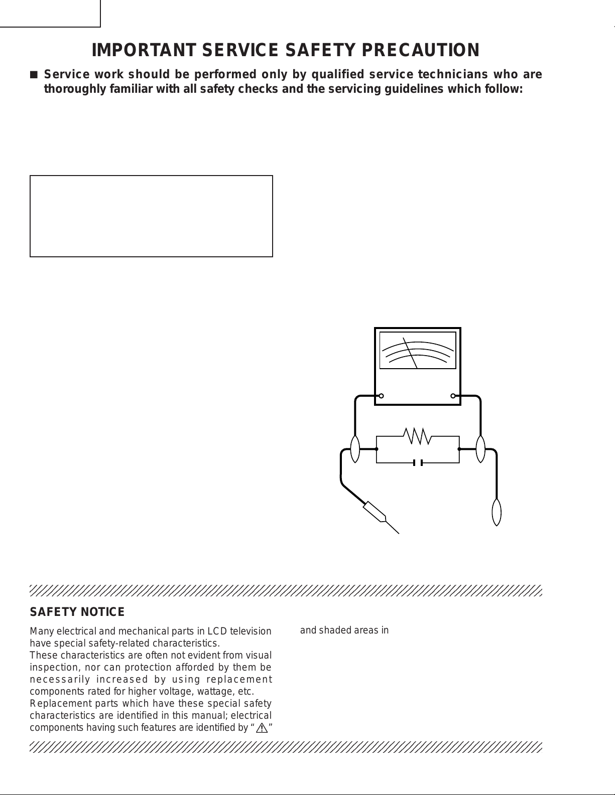
3. To be sure that no shock hazard exists, check for
leakage current in the following manner.
• Plug the AC cord directly into a 110~240 volt A C outlet,
and connect the DC power cable into the receiver's
DC jack. (Do not use an isolation transformer for this
test).
• Using two clip leads, connect a 50k ohm, 10 watt
resistor paralleled by a 0.15µF capacitor in series with
all exposed metal cabinet parts and a known earth
ground, such as electrical conduit or electrical ground
connected to an earth ground.
• Use an AC voltmeter ha ving with 5000 ohm per volt, or
higher, sensitivity or measure the AC voltage drop
across the resistor.
• Connect the resistor connection to all exposed metal
parts having a return to the chassis (antenna, metal
cabinet, screw heads, knobs and control shafts,
escutcheon, etc.) and measure the AC voltage drop
across the resistor.
All checks must be repeated with the AC cord plug
connection reversed. (If necessary, a nonpolarized
adaptor plug must be used only for the purpose of
completing these checks.)
Any reading of 0.75V peak (this corresponds to 0.5
mA. peak AC.) or more is excessive and indicates a
potential shock hazard which must be corrected before
returning the monitor to the owner.
DVM
AC SCALE
50k ohm
10W
0.15 µF
TEST PROBE
TO EXPOSED
METAL PARTS
CONNECT TO
KNOWN EARTH
GROUND
234567890123456789012345678901212345678901234567890123456789012123456789012345678901234567890121
SAFETY NOTICE
Many electrical and mechanical parts in LCD television
have special safety-related characteristics.
These characteristics are often not evident from visual
inspection, nor can protection afforded by them be
necessarily increased by using replacement
components rated for higher voltage, wattage, etc.
Replacement parts which have these special safety
characteristics are identified in this manual; electrical
and shaded areas in the
Schematic Diagrams.
For continued protection, replacement parts must be
identical to those used in the original circuit.
The use of a substitute replacement parts which do not
have the same safety characteristics as the factory
recommended replacement parts shown in this service
manual, may create shock, fire or other hazards.
components having such features are identified b y “ å”
234567890123456789012345678901212345678901234567890123456789012123456789012345678901234567890121
234567890123456789012345678901212345678901234567890123456789012123456789012345678901234567890121
2
Replacement Parts Lists and
Page 3
LC-20B4M
Precautions for using lead-free solder
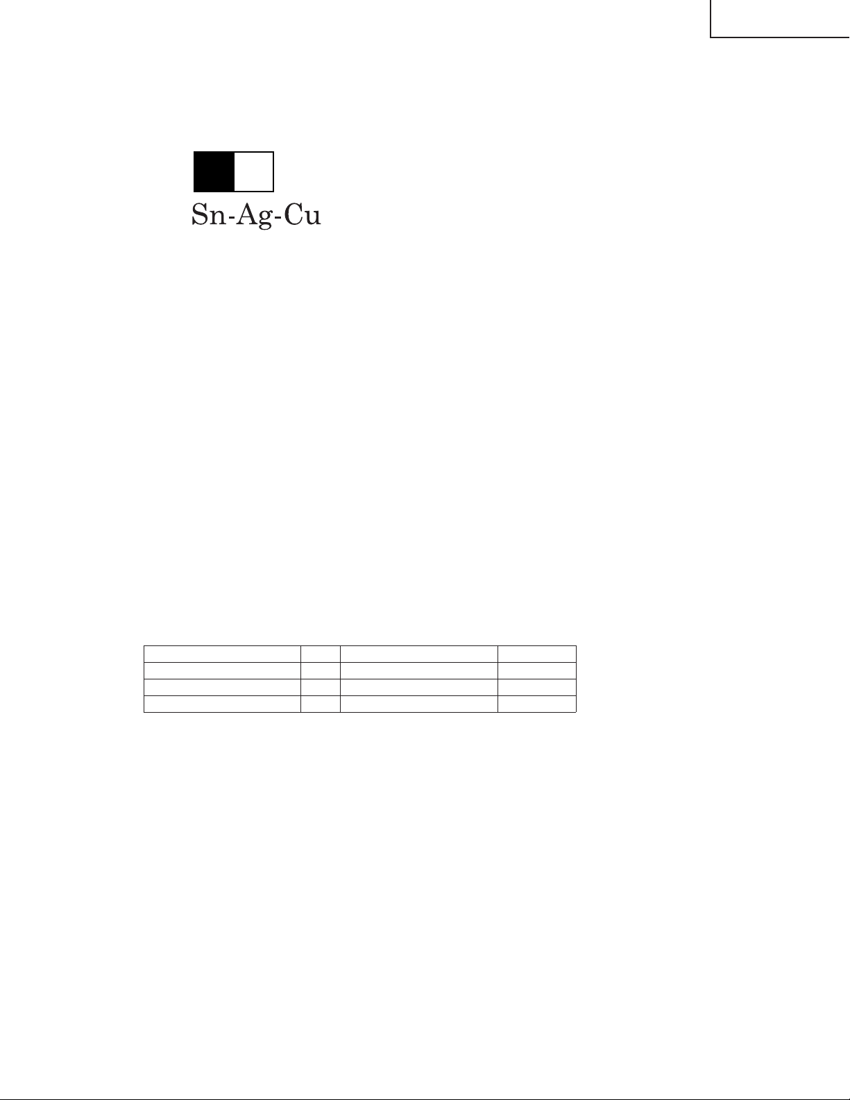
1 Employing lead-free solder
"All PWBs" of this model employs lead-free solder. The LF symbol indicates lead-free solder, and is attached on
the PWBs and service manuals. The alphabetical character following LF shows the type of lead-free solder.
Example:
L Fa
Indicates lead-free solder of tin, silver and copper.
2 Using lead-free wire solder
When fixing the PWB soldered with the lead-free solder, apply lead-free wire solder. Repairing with conventional
lead wire solder may cause damage or accident due to cracks.
As the melting point of lead-free solder (Sn-Ag-Cu) is higher than the lead wire solder by 40°C, we recommend
you to use a dedicated soldering bit, if you are not familiar with how to obtain lead-free wire solder or soldering bit,
contact our service station or ser vice branch in your area.
3 Soldering
As the melting point of lead-free solder (Sn-Ag-Cu) is about 220°C which is higher than the conventional lead
solder by 40°C, and as it has poor solder wettability, you may be apt to keep the soldering bit in contact with the
PWB for extended period of time. However, Since the land may be peeled off or the maximum heat-resistance
temperature of parts may be exceeded, remov e the bit from the PWB as soon as you confirm the steady soldering
condition.
Lead-free solder contains more tin, and the end of the soldering bit may be easily corroded. Make sure to turn on
and off the power of the bit as required.
If a different type of solder stays on the tip of the soldering bit, it is allo y ed with lead-free solder. Clean the bit after
every use of it.
When the tip of the soldering bit is blackened during use, file it with steel wool or fine sandpaper.
Be careful when replacing parts with polarity indication on the PWB silk.
Lead-free wire solder for servicing
Part No, ★ Description Code
ZHNDAi123250E J φ0.3mm 250g(1roll) BL
ZHNDAi126500E J φ0.6mm 500g(1roll) BK
ZHNDAi12801KE J φ1.0mm 1kg(1roll) BM
3
Page 4
LC-20B4M
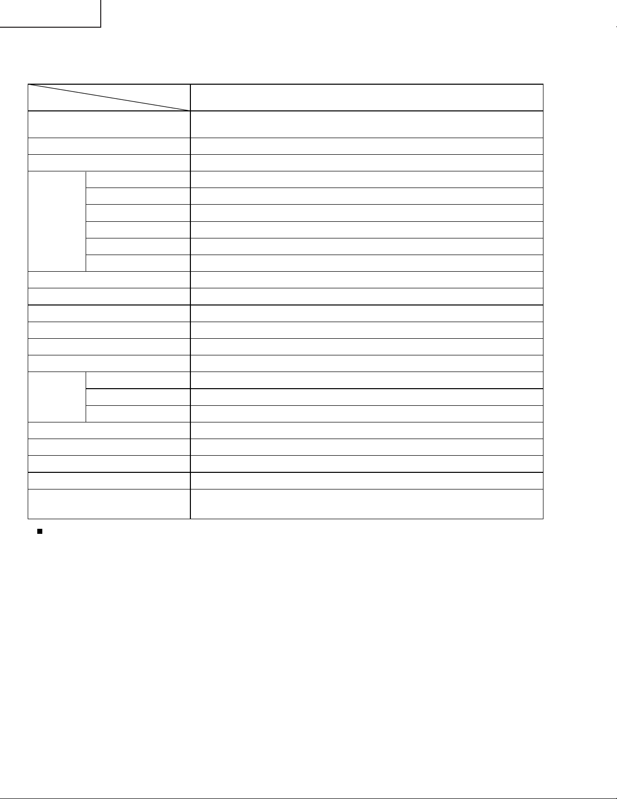
SPECIFICATIONS
MODEL
ITEMS
LCD panel
Number of dots
Video colour systems
TV Standard
TV T uning System
TV
FUNCTION
4-LINE DIGITAL COMB FILTER
Brightness
Lamp life
Viewing angles
Audio output
Speakers
Terminals
Headphone jack
OSD LANGUAGE
Power requirement
Weight
Accessories
STEREO/BILINGUAL
Universal R/C for TV only
AUTO PRESET
CATV
AV2 IN/OUT
Component
LC-20B4M
19.7" (50 cm) Advanced Super
View & BLACK TFT LCD
921,600 dots VGA
World multi system
I/DK/M/BG
Auto preset tuning
NICAM-BG, I, DK/IGR-BG
Yes
Yes
S1~S41 ch. Hyper Band
Yes
430 cd/m
60,000 hours
H: 170° V: 170°
2.5 W × 2
5 cm ø, 2 pcs.
AV1
Composite Video, S-Video, Audio
Composite Video/Audio
Y, P
3.5 mm ø jack (Rear)
English/Chinese/Arabic
DC 13V, AC10-240V, 50/60Hz
8.7 kg w/o accessories
Wireless Remote Control, Batteries, Cable clamps, AC adapter, AC cord,
Operation manual, Antenna cable
2
B
, PR/Audio
As a part of policy of continuous improvement, SHARP reserves the right to make design and specification
changes for product improvement without prior notice. The performance specification figures indicated are nominal
values of production units. There may be some deviations from these values in individual units.
4
Page 5
CH
MENU
TV/VIDEO MAIN POWER
PRESET
1
2
VOL
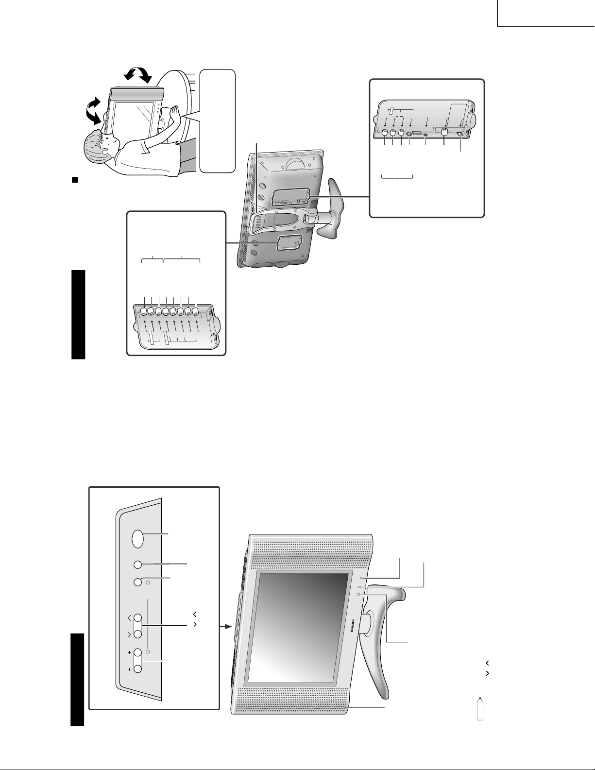
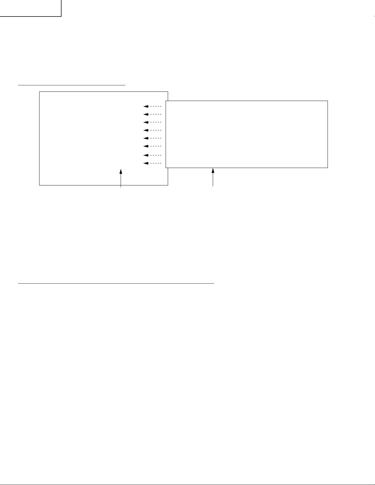
Upper control panel
MENU
MAIN POWER
TV/VIDEO
CH( )/( )
VOL (
-
)/(+)
P
O
W
E
R
S
L
E
E
P
SLEEP indicator
The SLEEP indicator lights up red when the
SLEEP TIMER is set to on.
Remote sensor window
Power/Standby indicator
A green indicator lights when the power is on
and a red indicator lights when in the standby
mode (the indicator will not light when the
main power is off).
Note:
•
TV/VIDEO, CH (
)/( ), and VOL (–)/(+) on the main unit have the same functions as the same buttons on the remote
control. Fundamentally, this operation manual provides a description based on operation with the remote control.
Main unit (front view)
* The examples used throughout this manual are based on the LC-20B4M
model.
Speaker
To change the vertical angle of the
LCD TV set, tilt the screen up to 5
degrees forward or 10 degrees
backward. The TV set can also be
rotated 25 degrees to right and left.
Please adjust the angle so that the
TV set can be watched most
comfortably.
Main unit (rear view)
V
O
L
C
H
ME
N
U
T
V
/V
ID
E
O
M
AI
N
P
O
W
E
R
A
N
T
.
V
IDE
O
S
-
VIDE
O
A
U
D
I
O
L
R
H
E
A
D
P
H
O
N
E
A
V
-
IN
1
VIDEO
AV-IN1
AUDIO (L)
AUDIO (R)
S-VIDEO
HEADPHONE
Antenna terminal
POWER INPUT
DC 13V
V
I
DE
O
A
U
D
I
O
L
Y
P
B
P
R
R
A
U
D
I
O
L
R
C
O
M
P
O
N
E
N
T
A
V
-
IN2
/
O
U
T
Y
VIDEO
AV-IN2/OUT
COMPONENT
AUDIO (L)
AUDIO (R)
P
B
P
R
AUDIO (L)
AUDIO (R)
Carrying handle
P
O
W
E
R
I
N
PU
T
D
C
13
V
U
S
E
TH
E
SU
PP
L
I
E
D
A
C
AD
A
PT
E
R
.
(
P
AR
T
N
O
.
L
O
C
A
T
ED
O
N
T
H
E
M
O
D
E
L
L
A
BE
L
.
)
How to adjust the angle
Tilt the display by grabbing onto the
carrying handle while securely
holding down the stand with your
other hand.
OPERATION MANUAL
LC-20B4M
5
Page 6
LC-20B4M
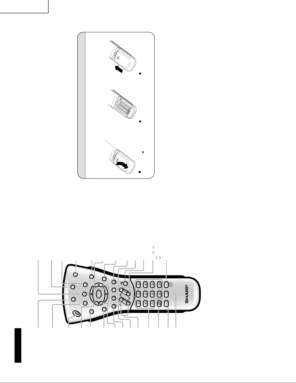
Remote control
MENU
Displays the TV menu.
SUBTITLE
Displays the Teletext
Subtitle directly.
HOLD
Temporarily holds the
current Teletext page.
MUTE
Switches the sound on and off.
Yellow
Cyan
CHANNEL SELECT
OK
VOL (+)/(
-
)
Flashback
Returns to the previous
channel.
Red
Upwards/ Downwards
Selection, zoom display
function (Teletext mode)
END
TEXT
Displays the Teletext mode
screen.
POWER
MPX
Switches Audio
mode.
REVEAL
Displays hidden information
such as solutions to riddles
and puzzles.
Right / Left Selection
SUBPAGE
Displays the Teletext
Subpage directly.
TV/VIDEO
Switches the input source
between AV1, AV2, COMPONENT
and TV mode.
BRIGHT
Selects the brightness
of the display.
Green
CH
MENU
E
TV/VIDEO
R
E
V
E
AL
HOLD
END
M
MENUSOUND
SU
BTITLE
SUBPAGE
T
E
X
T
ROTATE
W
IDE
T
CHVOL
MENU
SLEEP DIS.MODE
OKMPX
SUBTITLE END
HOLD
SUBPAGE
REVEAL
TEXTBRIGHT
TV/VIDEOPOWER
SLEEP
DIS.MODE
DISPLAY
Press....Displays receiving channel
for 10 seconds. Channel
indication reduces in size
after about 10 seconds.
Press again...Removes display.
CH ( )/( )
Selects next higher channel.
Selects next lower channel.
Batteries for Remote Control
Before using the LCD TV set for the first time, install two (“AAA” size, UM/SUM-4) batteries (supplied).
When the batteries become depleted and the remote control fails to operate, replace the batteries with
new (“AAA” size, UM/SUM-4) batteries.
1
Open the battery
cover.
2
Insert two (“AAA” size,
UM/SUM-4) batteries.
3
Close the battery
cover.
Slide the cover while
pressing the (
) part.
Position the positive and
negative ends of the
batteries as indicated in the
compartment.
Engage the claw on the
cover into the battery
housing and slide shut.
6
Page 7
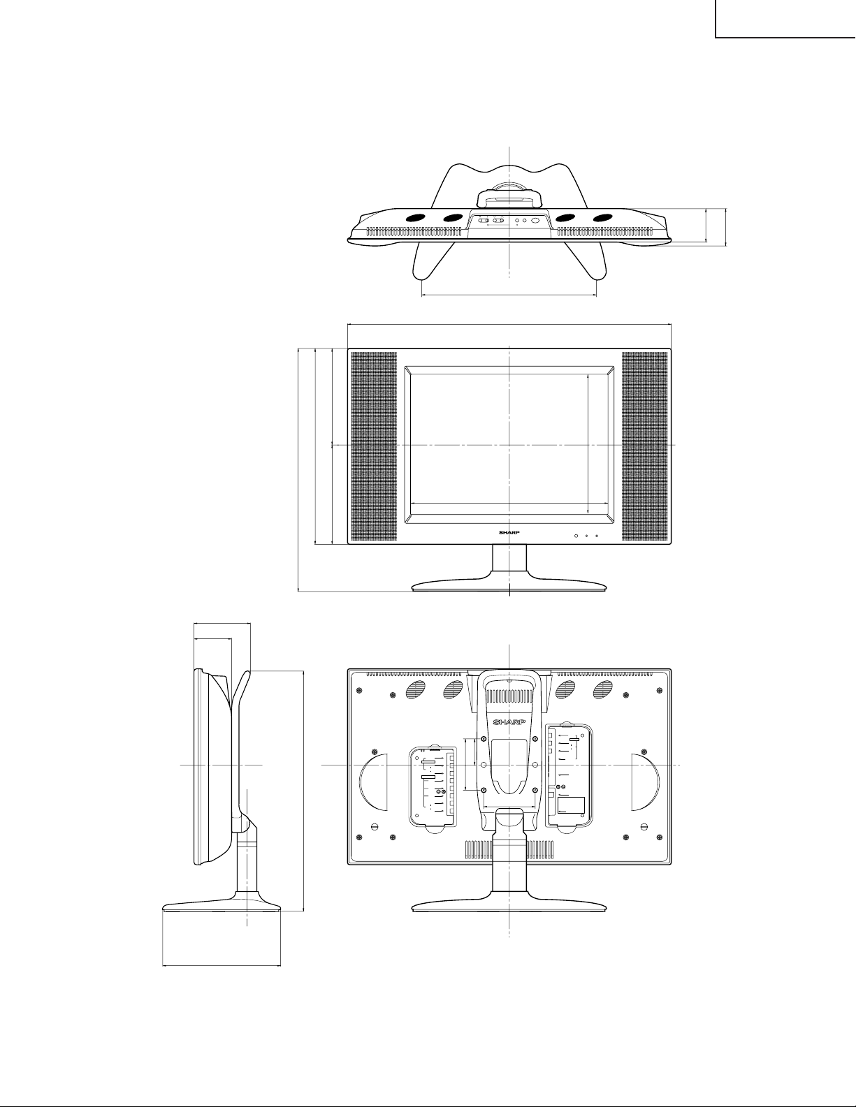
DIMENSIONS
CHVOL T V/VIDEOMENU MAIN POWER
2
1
PRESET
420
630
Unit: mm
68.6
76.1
LC-20B4M
76.1
110.7
471.5
470.3
381.5
193.5 188
VIDEO
AV-IN 2/OUT
AUDIO
COMPONENT
AUDIO
300.8
403.3
POWER
SLEEP
VIDEO
AV-IN1
L
AUDIO
R
100
51.5
100
L
R
Y
P
B
R
P
L
R
S-VIDEO
HEAD
PHONE
ANT.
USE THE SUPPLIED
AC ADAPTER.
(PART NO. LOCATED ON
THE MODEL LABEL.)
POWER INPUT
DC13V
249.6
7
Page 8
LC-20B4M
SC1204
SC3403
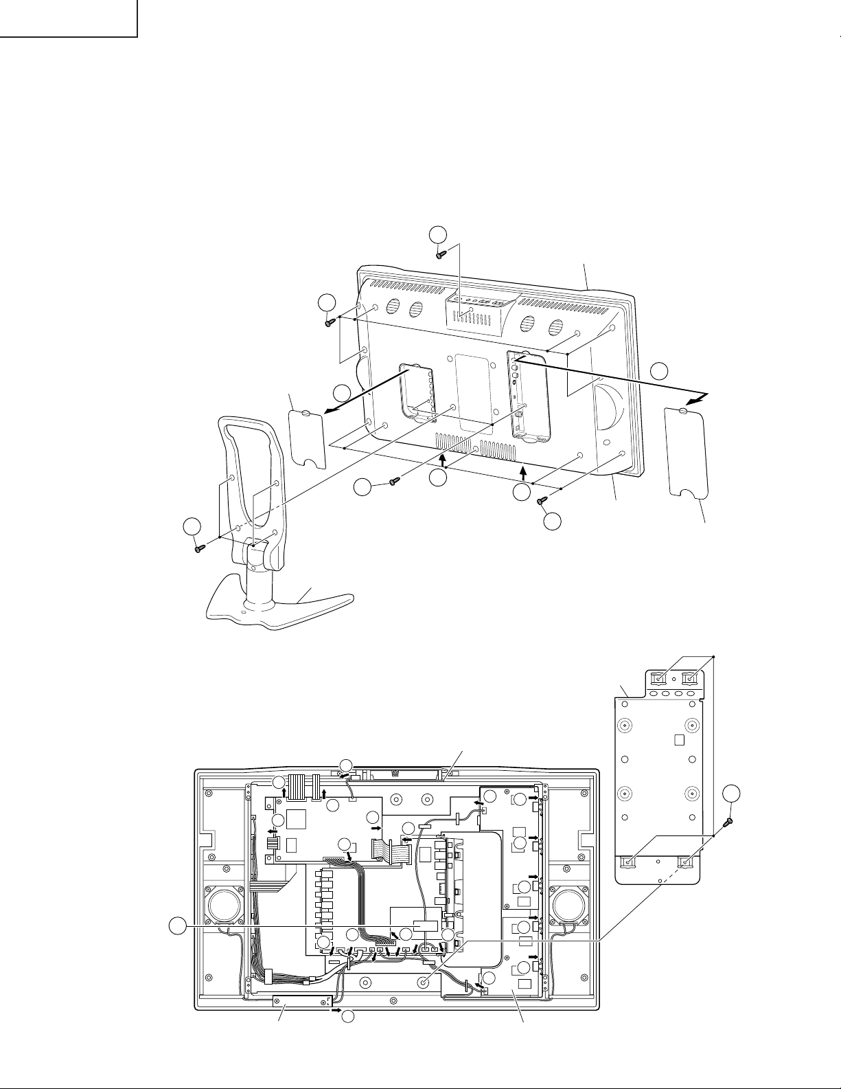
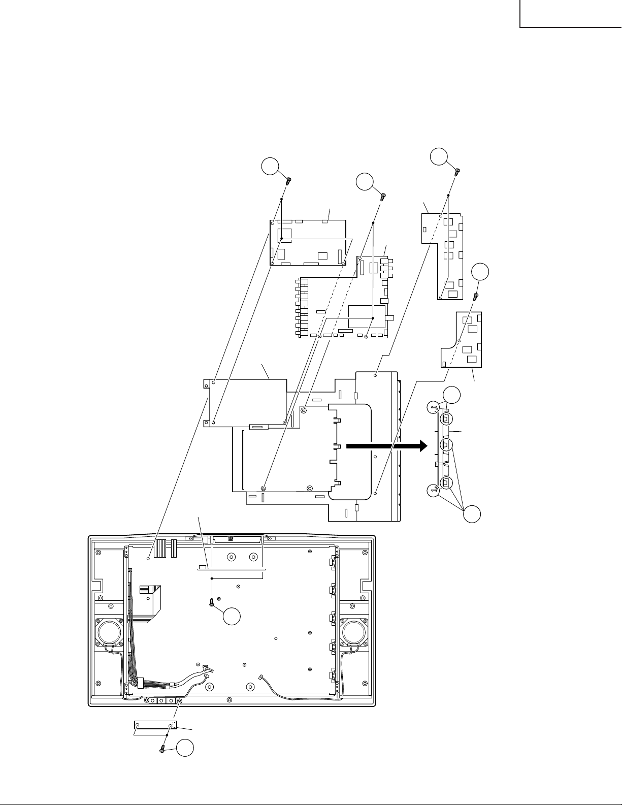
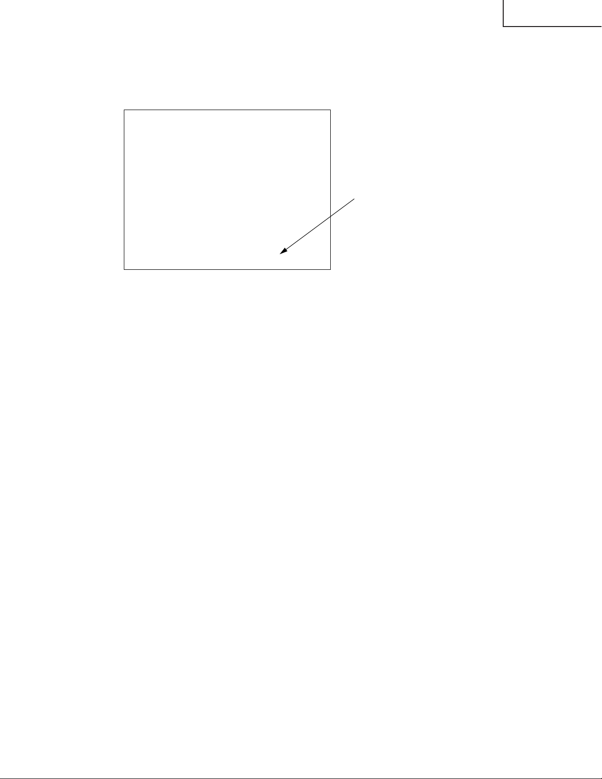
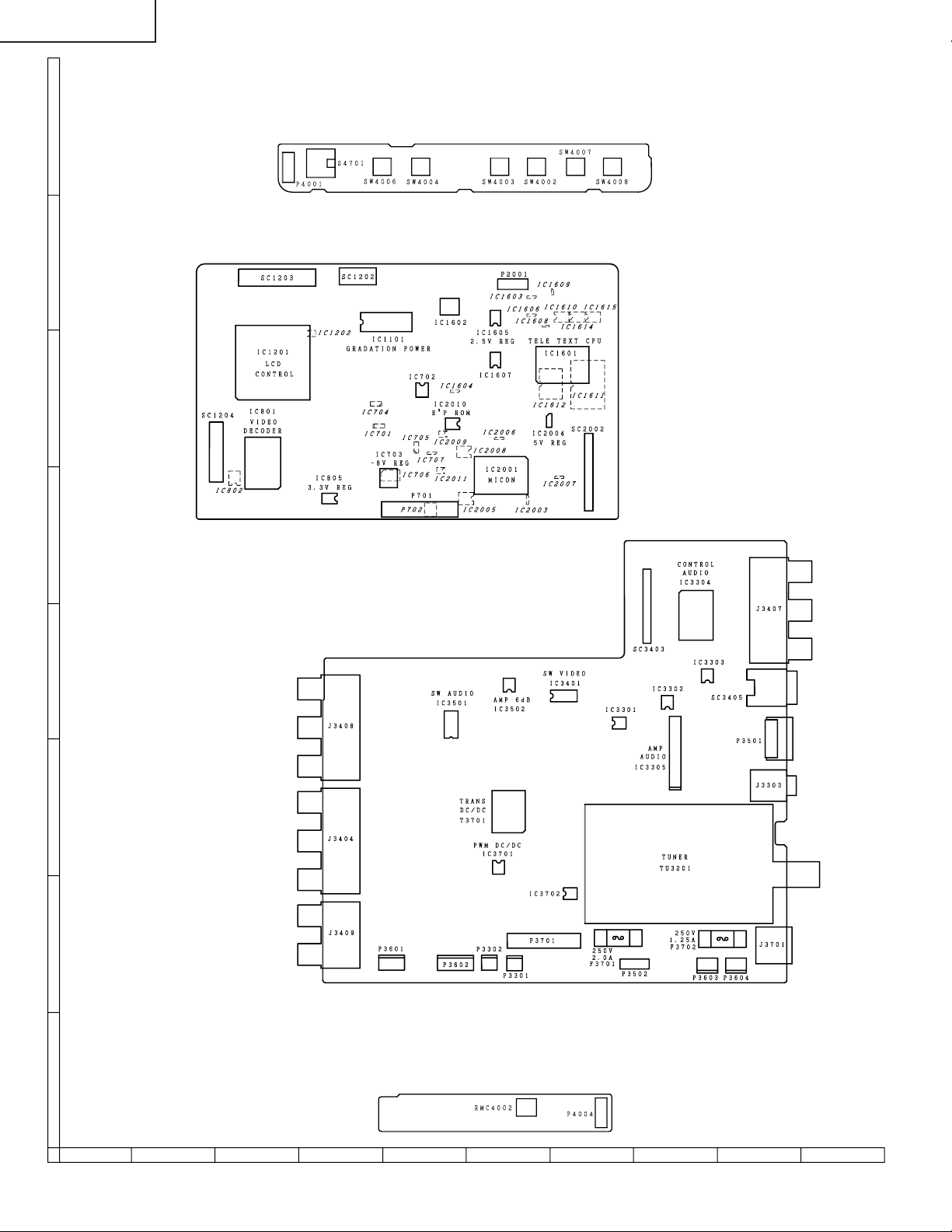
REMOVING OF MAJOR PARTS
1. Remove the stand fixing screws (4 pcs.).
2. Remove the two terminal covers.
3. Remove the terminal section fixing screws (2 pcs.).
4. Remove the cabinet B fixing screws (12 pcs.).
5. Remove the cabinet B after opening from the direction of an arrow.
6. Remove the reinforcement angle fixing screws (4 pcs.).
7. Release peel off the tape.
8. Detach the connector from each PWB.
4
Terminal Cover (S)
2
4
Cabinet A
R
E
W
O
P
N
I
A
M
O
E
D
I
V
/
V
T
U
N
E
M
H
C
L
O
V
2
3
5
5
Cabinet B
1
4
Terminal Cover (L)
Stand
Reinforcement Angle
Operation PWB
8
8
8
SC1204
SC1204
SC1202SC1203
8
Main PWB
8
P701
P2001
P4001
SC2002
8
SC3403
SC3403
Tuner PWB
8
8
P6705
Inverter-A
8
PWB
6
8
8
7
Tape
R/C, LED PWB
P4004
8
P6706
Inverter
8
8
-B PWB
P3701
P3301
8
P3502
P3603P3603
8
P3604
8
P3302
P3302
8
P3601
P3602
8
8
Page 9
9. Remove the inverter-A PWB fixing screws (2 pcs.).
12
9
10
Inverter-A
PWB
Main PWB
Chassis Frame
Chassis Frame Cover
Tuner
PWB
Inverter-B
PWB
Operation PWB
14
13
R/C, LED PWB
11
12
12
10. Remove the inverter-B PWB fixing screw (1 pc.).
11. Remove the main PWB fixing screws (3 pcs.).
12. Remove the tuner PWB fixing screws (3 pcs.) and detach the chassis frame cover fixing hooks.
13. Remove the R/C, LED PWB fixing screws (2 pcs.).
14. Remove the operation PWB fixing screws (2 pcs.).
LC-20B4M
9
Page 10
LC-20B4M
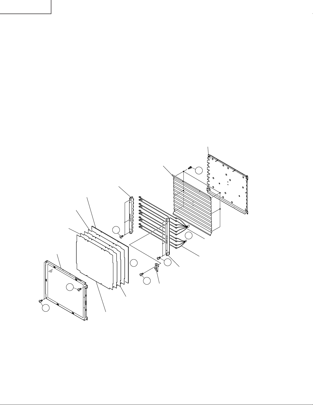
» Precautions in handling the LCD panels
1. Work in a clean room (with humidities below 50%).
2. Be sure to wear an anti-static armband.
3. Handle the panels on an electro-conductive mat.
4. Be careful not to fall, shake and shock the panels.
15. Remove the LCD panel unit fixing screws (4 pcs.).
16. Remove the ITO earth spring fixing screw (1 pc.).
17. Remove the reflection/deflection, prism, diffusion, ITO sheets and diffusion panel.
18. Remove the lamp fixing holder fixing screws (6 pcs.).
19. Detach the lamp unit-A/B.
20. Remove the reflection mirror fixing screws. (6 pcs.).
Back shield
(PSLDM4685CEFW)
Diffusion Panel
(PCOVU0107CEZZ)
ITO Sheet
(PSHEP0289CEZZ)
Prism Sheet
(PSHEP0287CEZZ)
20" LCD Panel Unit
15
15
Reflection Mirror
(PMiR-0296CEZZ)
Lamp Fixing Holder
(LHLDZ2176CEZZ)
18
17
Diffusion Sheet
(PSHEP0288CEZZ)
Reflection/Deflection Sheet
(PSHEP0286CEZZ)
18
16
ITO Earth Spring
(MSPRP1220CEFW)
21
19
Lamp Unit-A
(KLMP-0124CEZZ)
Lamp Unit-B
(KLMP-0125CEZZ)
Lamp Fixing Holder
(LHLDZ2176CEZZ)
10
Page 11

LC-20B4M
Precautions at the time of the side B(back) service of digital unit.
1. Remove only SC2002 of the FFC for connection between Main unit (SC2002) and Tuner unit(SC3403), and connect the extended cable (QCNW-A556WJZZ) for service.
2. Remove the FFC for connection between Main unit (SC1204) and LCD panel unit, and connect the extended
cable (QCNW-A553WJZZ) for service.
3. Remove the FFC for connection between Main unit (SC1203) and LCD panel unit, and connect the extended
cable (QCNW-A556WJZZ) for service.
4. Remove the FFC for connection between Main unit (SC1202) and LCD panel unit, and connect the extended
cable (QCNW-A555WJZZ) for service.
5. Remove only P701 of the Connecting Cord f or connection between Main unit (P701) and Tuner unit (P3701), and
connect the extended cable (QCNW-B194WJZZ) for service.
6. Remove the main unit fixing screws (3 pcs.), a substrate is reversed.
Main PWB
(Side B)
6
3
SC1202
2
SC1203
SC1204
4
Main PWB
5
P701
P2001
1
SC2002
Tuner PWB
SC3403
P3701
Step Part No. Description
1 QCNW-A556WJZZ Extension Cable 50-pin Main (SC2002)-Tuner (SC3403)
2 QCNW-A553WJZZ Extension Cable 30-pin Main (SC1204)-LCD Panel
3 QCNW-A556WJZZ Extension Cable 50-pin Main (SC1203)-LCD Panel
4 QCNW-A555WJZZ Extension Cable 20-pin Main (SC1202)-LCD Panel
5 QCNW-B194WJZZ Extension Cable 12-pin Main (P701)-Tuner (P3701)
11
Page 12

LC-20B4M
ADJUSTING PROCEDURE OF EACH SECTION
The best adjustment is made before shipping. If any position deviation is found or after part replace is performed, adjust
as follows.
Preparation for Adjustments
Use the exclusive-use AC adapter or stable DC power supply.
AC adapter: UADP-0241CEPZ
DC power supply: 13 ± 0.5V 5.4A
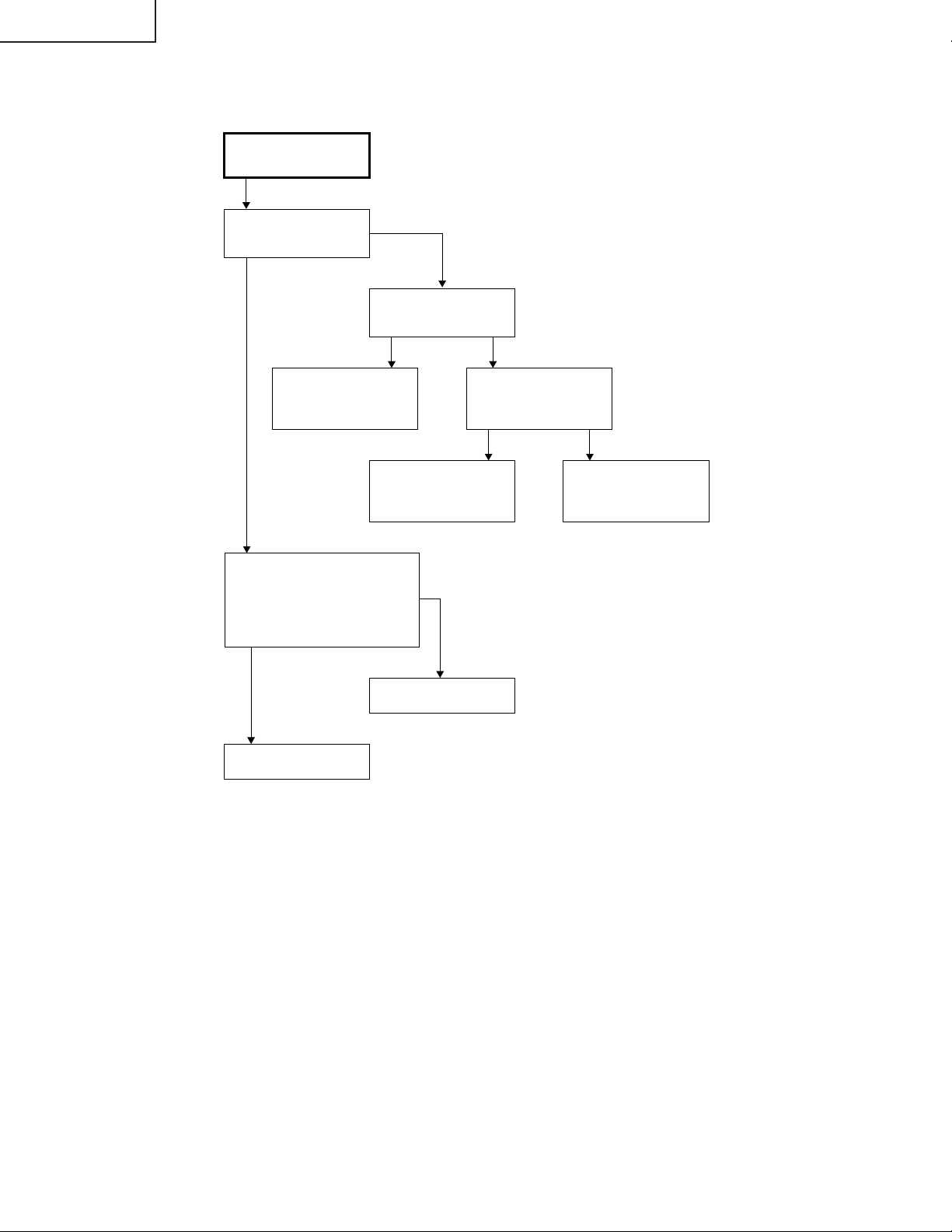
1. Adjustment Procedure
1-1. Adjusting the checker
Turning on the power (initialization) → Setting the model and size in inches → Transferring the model-specified
data to the E2PROM (I2C) → Calling the adjustment process mode → Starting the adjustment (+B adjustment)
1-2. Adjusting the finish process
Reassembling the set → Turning on the power → Calling the adjustment process mode (using the remote
controller) → Adjusting the counter bias, TV contrast and white balance
2. Calling the MAIN adjustment process mode
There are the following two ways to choose from.
• Set the Pin (81) (KEY4) or Pin (82) (KEY5) of IC2001 (microprocessor) to "L", turn on the power.
• For servicing, hold down the "TV/VIDEO" and "MENU" keys at once, and turn on the "POWER" switch. (Make
sure the process mode "K" appears at the top left of the screen.) Then press the "CH (Ù)" and "VOL (–)" keys
at once. (Make sure the adjustment process mode screen shows up.) To quit this mode, turn off the power. (Or
turn off the "POWER" switch or use the remote controller’s "OFF" key.)
3. Using the keys for the adjustment process
Selecting a reception channel
• Using the "CH (ù)/(Ù)" key, turn up and down reception (broadcasting) channels.
Just click on the key, and channels are selected on by one.
Hold down the key, and the next receivable channel is searched up and down.
• Adjustment items
Adjust each of the items by using the "MENU", "CURSOR UP/DOWN" and "VOL (+)/(–)" keys (on the set or on
the remote controller).
• Select an adjustment item using the "CURSOR UP/DOWN" key.
• An adjustment item is toggled on and off by activating the MENU SELECT key (next item).
Let’s suppose that the item at the bottom of a page is now selected. When the "MENU" key is activated here, the
item at the top of the next page will be selected.
4. Initialization
4-1. Set pins (81) and (82) of IC2001 (microprocessor) to GND. Turn on the power.
4-2. A model number is automatically selected. Make sure "A640M" is selected.
4-3. Select the inch size (20).
12
Page 13
LC-20B4M
5. Adjustment
5-1. +B adjustment (R3714 Variable resistor)
1) Receive the colour bar signal.
2) Adjust the voltage at pin (4) of P3701 to 5.00 ± 0.02 V.
Note: The 5.0 V level is used as reference for all the line voltages. Make this adjustment as precisely as
possible.
5-2. Counter bias adjustment: COM BIAS on page 2
Adjust the "COM BIAS" setting until the contrast gets optimum (the black portion blackest). The adjustment
guideline is around 98.
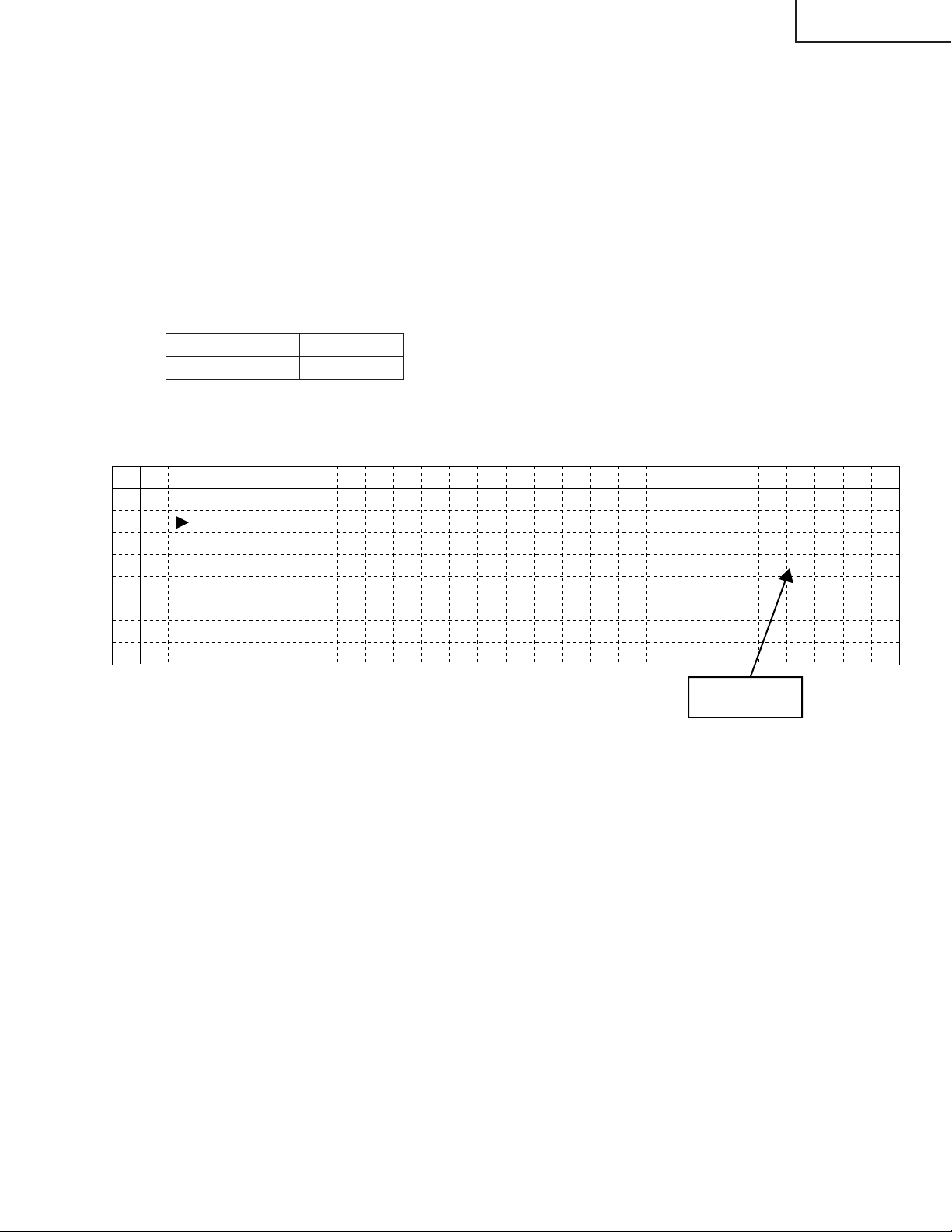
5-3. TAMP adjustment
1) Feed the colour bar pattern signal.
2) See if the "Y" reading on adjustment process page 2 is within the range shown below. If not, adjust the
"NTSC TAMP" setting to bring the "Y" reading within the specified range.
Model LC20B4M
Adjustment value 187~202
3) If the "NTSC TAMP" setting has been readjusted, write down its new setting in the "PAL TAMP" and
"SECAM TAMP" items manually.
(Page 2 of adjustment process OSD)
0 1 2 3 4 5 6 7 8 9 10 11 12 13 14 15 16 17 18 19 20 21 22 23 24 25 26
0
1
2
3
4
5
6
7
2
COM B I AS
TAMP L 817
YD TA
TAMP
NTSC TAMP
PAL TAMP 26
SECAM
A
H
TAMP
Y Data
(White 75%)
98
918
022
26
2
6
5-4. White balance adjustment
1) Feed the monoscope pattern signal.
2) Adjust the "RCUTOFF" and "BCUTOFF" settings on adjustment process page 3 to achieve the color at the
same level as with the standard set.
13
Page 14
LC-20B4M
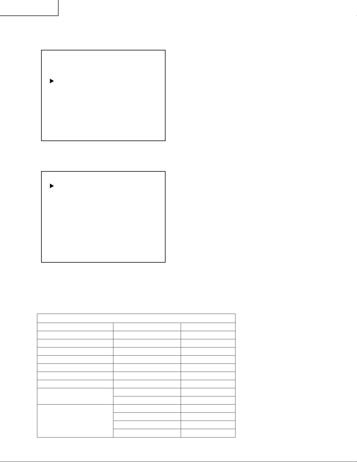
5-5. Other adjustments (SOUND, VPC, DPS, DAC, TUNER, OTHERS, TEXT)
1) Move the cursor to a desired item on page 4 of adjustment process menu. Press the CURSOR LEFT/
RIGHT keys, "VOL (+)/(–)" keys or OK key to select the item.
4
I2C DATA 000000000000
I2C DATA WAIT
SOUND
VPC
DPS
DAC
TUNER
OTHERS
TEXT
2) The adjustment process menu of the item appears on the screen. The settings are now ready to change.
Screen with SOUND selected
SOUND1
VOLUME 0
AVC OFF
MSP DATA 0000000000
MSP DATA WAIT
0018H ST 1D
ONTA 1
CARRIER MUTE ON
SP TEST OFF
3) To go back to page 4 of adjustment process menu, press the FLASHBACK key on the remote controller.
5-6. Writing the model-by-model data
For the Ver. 0.96A (P.P.) /1.00A (1st~) microprocessor, get it initialized first and then make the settings, listed
below, on it. (The microprocessor version is indicated at the bottom of Adjustment Process Page1.)
Ver. 0.96A/1.00A data reprogramming (INCH SIZE [20] , MODEL:A640M)
Adjustment process page Item OSD settings
DPS01 N358 BRIGHTNESS +15 → -16
DPS16 PAL BRIGHTNESS +10 → -21
DPS21 SECAM BRIGHTNESS +10 → -21
DPS26 PAL60 BRIGHTNESS +5 → -26
DPS31 N443 BRIGHTNESS 0 → -31
DPS45 DPS NLC A6 E4 → FF
TEXT2 TEXTMIX CTI7D 16 → 0
TEXT3 TEXTALL BRT -55 → -40
TEXTALL CON 27 → 28
TEXT6 TEXTALL LTI 139 → 129
TEXTMIX LTI 139 → 129
TEXTALL LMIX78 66 → 79
TEXTMIX LMIX78 66 → 79
14
Page 15

6. Lamp error detection
6-1. Functional description
This LCD colour television has a function (lamp error detection) to be turned OFF automatically for safety
when the lamp or lamp circuit is abnormal.
If the lamp or lamp circuit is abnormal, or some other errors happen, and the lamp error detection is
executed, the followings occur.
1 The main unit of television is turned OFF 5 seconds after it is turned ON. (The power LED on the front side
of TV turns from green to red.)
2 If the situation 1 happens 5 times sequentially, television can not be turned ON. (The power LED remains
red.)
6-2. Countermeasures
6-2-1. Check when turning OFF the lamp error detection
When television is turned OFF by the lamp error detection mentioned above, it enters the adjustment
process with the power LED red. Entering the adjustment process turns OFF the error detection and
turns ON TV.
This enables the operation check to detect errors in the lamp or lamp circuit.
Check whether "ERROR NO RESET" on line 4, page 1 of the adjustment process is 1 or more. If it is 1 or
more, it indicates the lamp error detection was executed.
6-2-2. Resetting of the lamp error count
After confirming that the lamp or lamp circuit is normal, reset the lamp error count. Select "ERROR NO
RESET" on line 4, page 1 of the adjustment process and set the number to 0 using the volume button.
LC-20B4M
Page 1 of the adjustment process
1
M O D E L A640M
I N C H S I Z E 20
E R R O R N O R E S E T 5
P U B L I C M O D E ON
E X T C O N T R O L OFF
V P C S H A R P N E S S ON
V P C F P 2 F H R E A D OFF
E X T M O D E UART
U P D A T E M O D E NORMAL
T E X T R E S E T OFF
V E R R O M 1. 0 0 G AI B U 0. 0 0 0
Reset 0
Afterwards, perform the operation check to confirm that the lamp error detection does not function.
15
Page 16
LC-20B4M
7. Public mode
• How to enter into PUBLIC MODE
1. Turn off TV by pressing MAIN POWER switch.
2. While pressing "VOL(+)" key and "CH(ù)" key at the same time, press MAIN POWER switch for more than
2 seconds.
TV will turn on, and you will see the screen display a setting of PUBLIC MODE.
• Setting screen of “PUBLIC MODE”
PUBLIC MODE
MAXIMUM VOLUME [ 60]
VOLUME FIXED [VARIABLE]
REMOTE CONTROL [RESPOND]
USER CONTROL [RESPOND]
ON SCREEN DISPLAY [YES ]
START MODE [NORMAL ]
INPUT MODE FIXED [VARIABLE]
SOUND ONLY MODE [NO ]
RESET
ENTER
1 ↔ 2 ··· ↔ 59 ↔ 60
VARIABLE ↔ FIXED
RESPOND ↔ LIMITED ↔ NO RESPOND
RESPOND ↔ NO RESPOND
YES ↔ NO
NORMAL ↔ AV1 ↔ COMPONENT ↔ CH1 ↔ CH2
VARIABLE ↔ FIXED
NO ↔ YES
↔ CH99 ↔ CH0
...
↔ CH98
Factory setting
Adjust setting
1. You can select each item of functions by pressing cursor UP/DOWN keys or CH(ù)/(Ù) Keys on the remote
control or CH(ù)/(Ù) keys on the LCD TV. The letter of selected item turns to yellow colour when you selected
it.
2. The setting position of each item of functions are made by pressing cursor RIGHT/LEFT keys on the remote
control or VOL (+)/(–)keys on the LCD TV.
3. Select ENTER position after you set all functions, and press cursor RIGHT/LEFT keys on the remote control
or VOL(+)/(–)keys on the LCD TV for confirmation.
Unless otherwise you make ENTER confirmation, the settings will not be memorized.
• 6-functions of Public Mode settings expand for public application
1. MAXIMUM VOLUME (1—————60)
You can set the maximum volume at your desire level.
2. VOLUME FIXED (VARIABLE / FIXED)
You can fix the sound volume at your desire level.
When you set to "FIXED", the sound volume which you just set is fixed.
3. REMOTE CONTROL (RESPOND / LIMITED)
If you set "LIMITED", remote control keys of POWER, CH(ù)/(Ù), VOL(–)/(+) and BRIGHT keys are
responded, but other keys are not responded.
This is a position that you can not make MENU adjustments.
4. USER CONTROL (RESPOND / NO RESPOND)
"NO RESPOND" means that the TV does not respond when you press a user control buttons except main
power button on the main unit.
5. ON SCREEN DISPLAY (YES / NO)
If you set "NO" position, OSD will not appear.
6. START MODE (NORMAL ↔AV1 ↔COMPONENT↔CH1↔CH2
...
↔CH98↔CH99↔CH0)
When any other item than "NORMAL" has been selected, the set gets started in the selected input mode or
channel at the next switch-on.
7. INPUT MODE FIXED (VARIABLE↔FIXED)
(* This item cannot be selected if the start mode is "NORMAL".)
If "FIXED" has been selected, any channels and input modes other than those selected in the start mode cannot
be picked up.
16
Page 17
LC-20B4M
8. SOUND ONLY MODE (NO↔YES)
(* This item cannot be selected if "NO" appears on the on-screen display.)
Let's suppose that this item has been selected and the BRIGHT key on the remote control has been pressed.
The item "BRIGHTNESS [OFF]" can now be selected next to the item "BRIGHTNESS [DARK]".
Screen with "BRIGHTNESS [OFF]" selected
Count-down started from 5
BRIGHTNESS [OFF] TURNS OFF IN 5 SECS.
Five seconds later, the screen shuts off and the sound alone is heard.
Once in this mode, no picture but the OSD appears. But the channels and sound volume can still be changed.
To quit this mode, press the BRIGHT key on the remote control again and select any item other than
"BRIGHTNESS [OFF]".
9. RESET
You can cancel all Public Mode settings. (It returns to the factory setting.)
10.ENTER
You make sure after you have specified all functions, then press the enter key. Unless otherwise you press
the enter key, all positions that you have selected will not be set.
17
Page 18
LC-20B4M
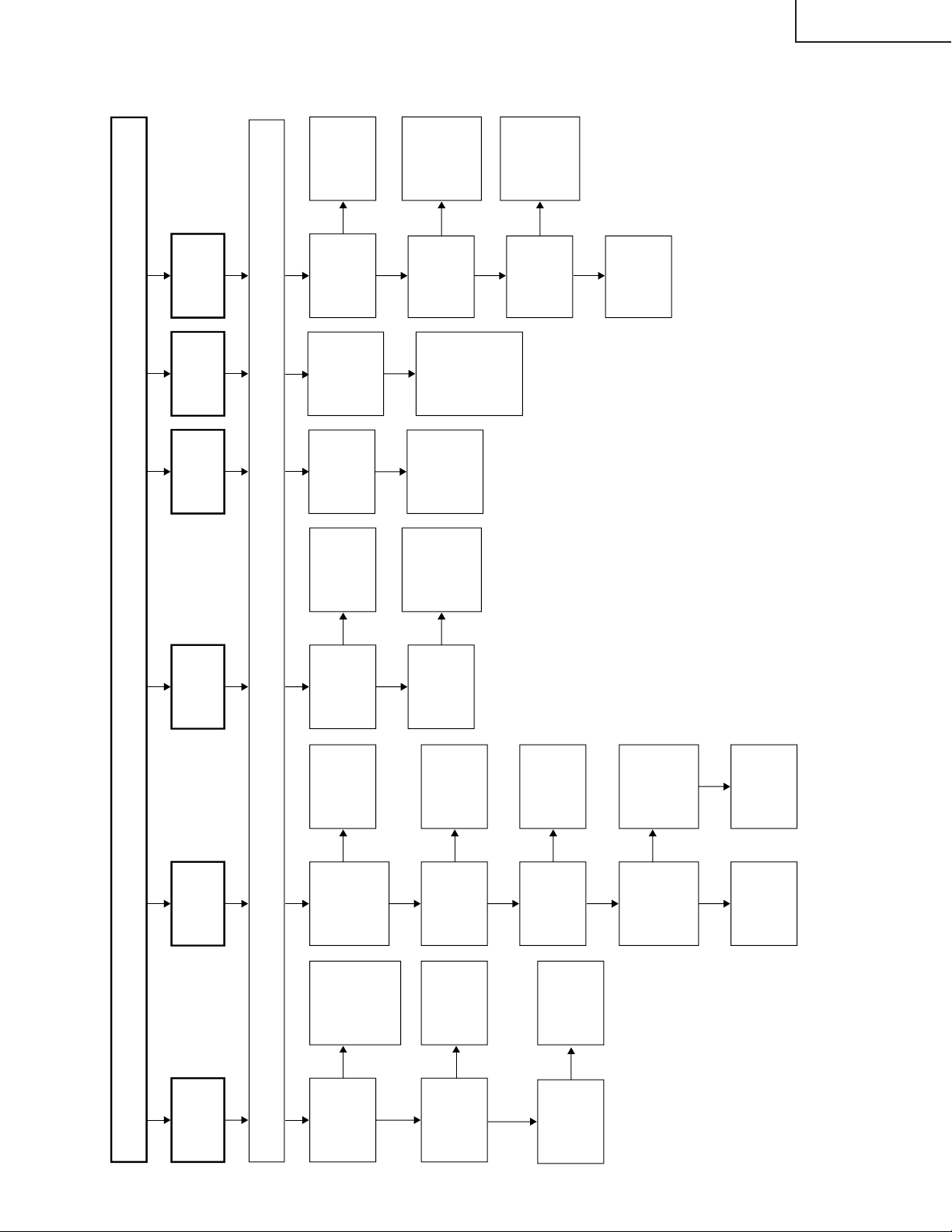
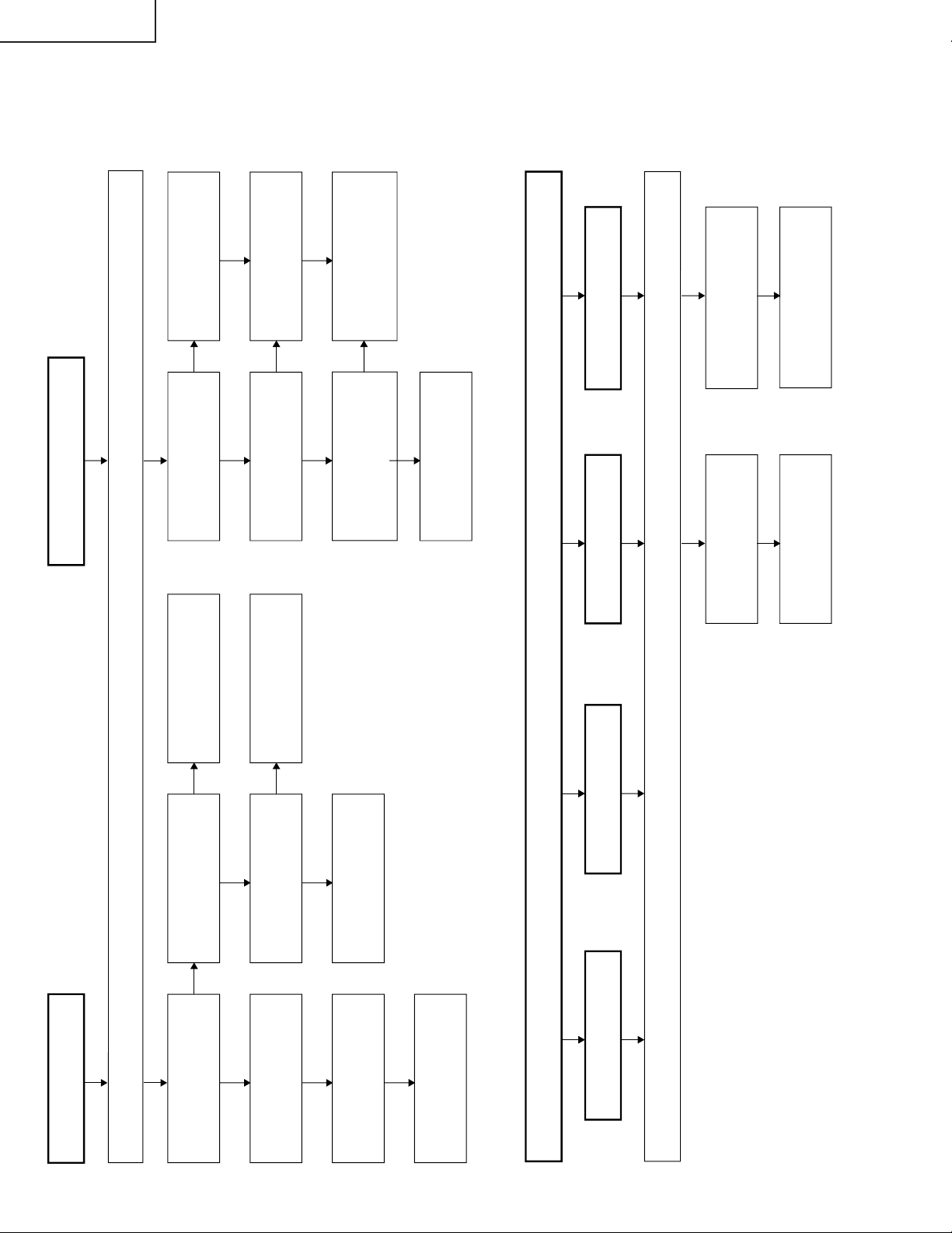
TROUBLE SHOOTING TABLE
No or Wrong
Picture
Does the IC801
test pattern appear
properly?
Yes
Check the IC801 signal
output line, IC801 itself
and its peripheral
circuits.
Are the waveforms at the signal
input pins of IC801 as specified?
TV/Composite Pin (73)
S Video Pins (72) and (73)
Component Pins (1), (2), (3)
and (75)
Yes
No
Does the IC1201 test
pattern appear
properly?
Yes
Check IC1201 and its
peripheral circuits as
well as the LCD panel
voltage and waveform.
Are the waveforms at
pins (8), (9), (26), and
(27) of IC1201
as specified?
Yes
No
No
No
Check the related lines,
IC801 itself and its
peripheral circuits.
Check IC801 and its
peripheral circuits.
Check the IC801 signal
input line.
18
Page 19
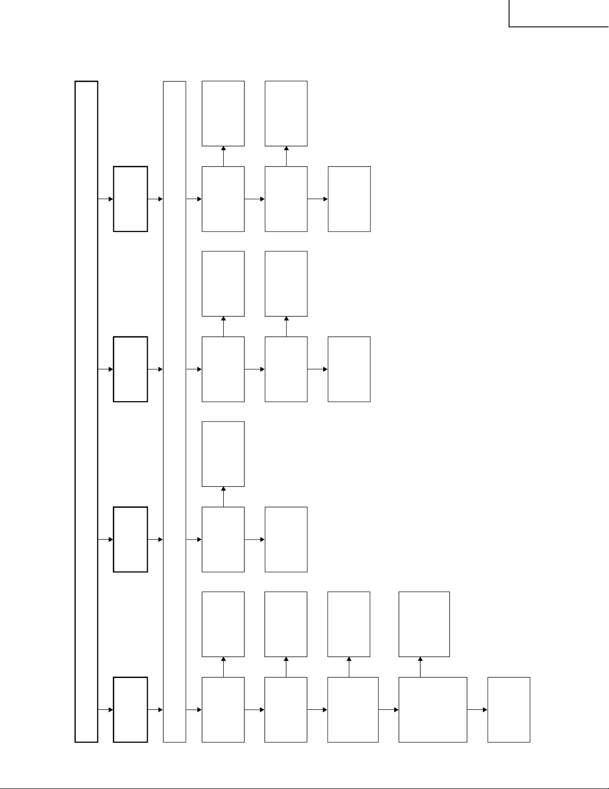
TROUBLE SHOOTING TABLE (Continued)
Check all the settings on the microprocessor
’s adjust process menu.
Are inputs
and outputs
of IC801 as
specified?
Does the DPS
test pattern
appear?
Does the
video decoder
test pattern
appear?
Check IC3401
and its
peripheral
parts.
Check
IC1201, its
peripheral
circuits and
the LCD
panel.
Check IC801
and its
peripheral
circuits.
Are inputs
and outputs
of IC3401 as
specified?
Check
IC3401 and
its peripheral
parts.
Is input at Pin
(73) of IC801
as specified?
Check IC801,
AV1 line and
their
peripheral
parts.
Are inputs and
outputs of
Q1602, Q1604
and Q1606 as
specified?
Check Q1602,
Q1604, Q1606
and its
peripheral
parts.
Is output at
pins (57)~(59)
of IC1601
normal?
Check the R,
G and B line.
Is input at
pin (21) of
IC1601
normal?
Check V2V0
line and its
peripheral
parts.
Check IC1601
and its
peripheral
parts.
Are inputs at
Pins (71) and
(72) of IC801
as specified?
Check
SC3405, SY
line, SC line
and peripheral
parts.
Is input at
Pins (4), (5),
(6) and (75)
of IC801 as
specified?
Check J3404,
DVD-Y line,
PB line, PR
line and
peripheral
parts.
Are voltages
at Pins (6),
(7) and (9) of
tuner as
specified?
Check the
power line.
Is output at
Pin (19) of
tuner as
specified?
Check the
tuner and its
peripheral
parts.
Is input at Pin
(16) of
IC3401 as
specified?
Check the
line in
question.
Check IC3401
and its
peripheral
parts.
Are Pins (3)
of IC3401 at
H?
Are Pins (48)
of IC2001 at
H?
Check the
line in
question.
No picture
No picture
at all
No VIDEO
1 or 2
output
No TELE
TEXT
output
No S
VIDEO
output
No
COMPONENT
output
No TV
output
Yes
No
Yes
No
No
No
Yes
No
No
Yes
Yes
No
No
Yes
No
No
Yes
No
Yes
No
No
Yes
Yes
No
Yes
LC-20B4M
19
Page 20
LC-20B4M
Do F3701 and F3702
function?
Check all the settings on the microprocessor
’s adjust process menu.
Are secondary outputs
(+38V, +9V, +5V, -11V) of
T3701 as specified?
Are the oscillation waveform
at T3701’s primary side as
specified?
Disconnect F3701 and
F3702. Is the load side
short-circuited?
Is any of T3701
’s primary
side, Q3703 and S4701 short-
circuited?
Check J3701, its peripheral
parts and connection cable.
Replace F3701 and F3702.
Check S4701 and
connection cable.
Check the secondary-side
load of T3701.
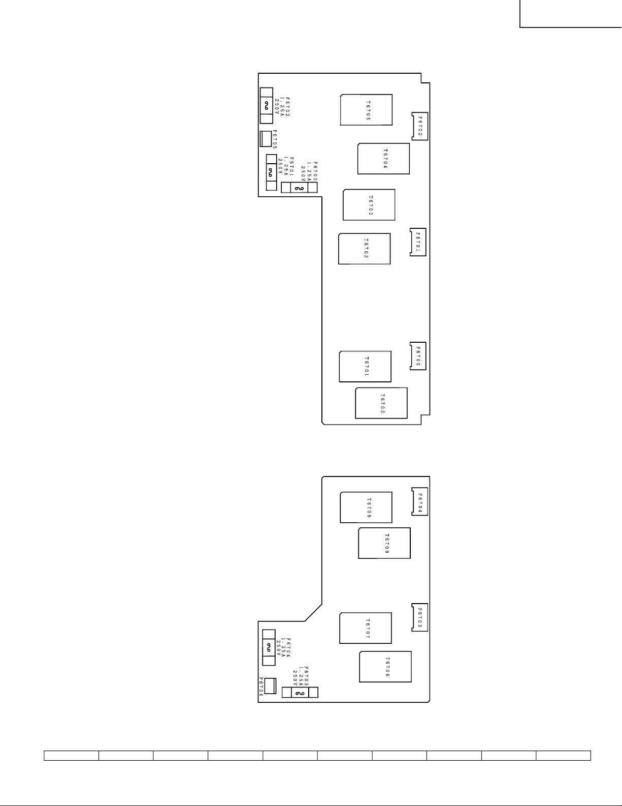
Do F6700, F6701,
F6702, F6703, and
F6704 function?
Is Pin (120) of IC1201 at
“H”?
Are the oscillation waveforms
at the primary side of T6700,
T6702, T6704, T6706, and
T6708 as specified?
Replace F6700, F6701,
F6702, F6703, and F6704.
Check the line, IC1201 and
its peripheral parts.
Check Q6700 - 6714, T6700
- 6709 and their peripheral
parts.
Replace the fluorescent lamp
and check the oscillation
waveform again.
Is input at Pin (72) of IC801
as specified?
Check SC3405, SC line and
peripheral parts.
Check all the settings on the microprocessor
’s adjust process menu.
Is input at Pins (1) and (3) of
IC801 as specified?
Check J3404, PB line, PR line
and peripheral parts.
No picture and sound
Yes
No
No
Yes
Yes
No
Yes
No
Fluorescent lamp failure
Yes
No
Yes
No
Yes
No
Yes
Yes
No colour
No TV colour No S-VIDEO colourNo VIDEO colour No COMPONENT colour
No No
TROUBLE SHOOTING TABLE (Continued)
20
Page 21
TROUBLE SHOOTING TABLE (Continued)
Is Pin (53) of
IC2001 at “L”?
Check all the settings on the microprocessor
’s adjust process menu.
Are outputs at
Pins (1) and (7)
of IC3301/
IC3303 as
specified?
Are inputs at
Pins (2) and (4)
as well as
outputs at Pins
(8) and (12), all
of IC3305, as
specified?
Muting effect is
on. Check the
FSMUTE line.
Check IC3301,
IC3303 and
their peripheral
parts.
Are input and
output of
IC3304 as
specified?
Check IC3304
and its
peripheral parts.
Check the line
in question,
IC3301 and its
peripheral
parts.
Check the
speakers and
their peripheral
parts.
Is Pin (55) of
IC2001 at “L”?
Check the
headphone and
its peripheral
parts.
Check Q2004,
J3303 harness
and their
peripheral parts.
Is Pin (58) of
IC2001 at “L”?
Are outputs at
Pins (14) and
(15) of IC3501
as specified?
Check the line
in question.
Check the
LMUTE line.
Check IC3501,
IC3304 and its
peripheral
parts.
Is output at Pins
(15) and (16) of
tuner as
specified?
Is input at Pin
(67) of IC3304
as specified?
Check IC3304,
X3301 and
their peripheral
parts.
Check the
tuner and its
peripheral
parts.
Check Q3201,
Q3202 and
their peripheral
parts.
No sound
from
speakers
No sound
No sound
from
headphone
No sound
from output
line
TV sound
failure
Yes
No
No
Yes
No
Yes
No
Yes
Yes
No
Yes
No
No
Yes
Yes
No
No
Yes
LC-20B4M
21
Page 22
LC-20B4M
CHASSIS LAYOUT
H
OPERATION Unit
MAIN Unit
G
F
E
D
C
B
A
TUNER Unit
R/C, LED Unit
22
87109654321
Page 23
INVERTER-A Unit
LC-20B4M
INVERTER-B Unit
23
1716 1918151413121110
Page 24
LC-20B4M
C
F
F
F
F
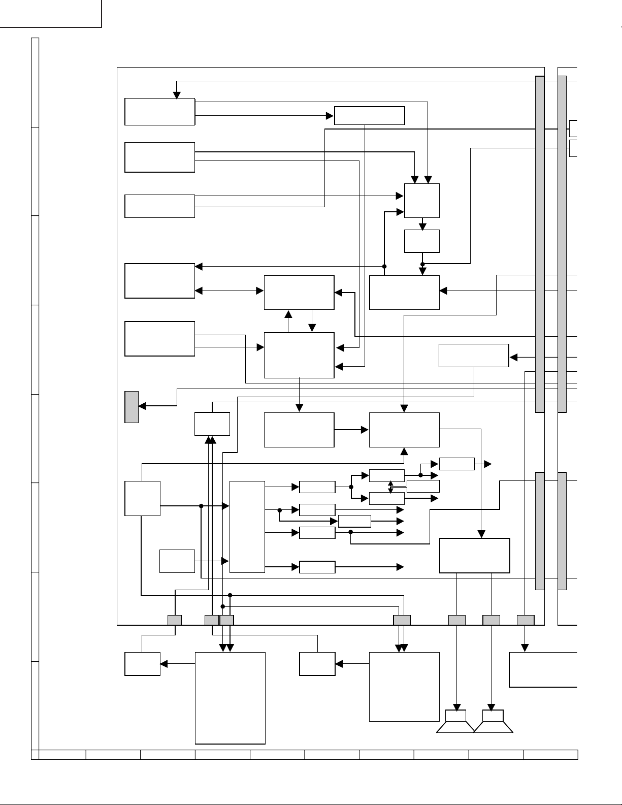
BLOCK DIAGRAM
AGC,AFT,SAW_SW,MODE 1,MODE 2
SC3403
S
H
TV_V
TUNER
TU3201
AV1
INPUT
SIF
V1_V
AV1 _L,R
SIF AMP
Q3201 ,Q3202
G
SY VIDEO
S-VIDEO
INPUT
F
AV2
INPUT/OUTPUT AUDIO IN/OUT VIDEO IN/OUT
COMPONENT
INPUT AUDIO
E
P3501
RXD,TXD
SC SWITCH V_IN
IC3401
AMP
IC3502
V2_V IN/OUT
AV2_L,R IN/OUT V_IN/OUT
SWITCH SWITCH
IC3501,Q3501 Q3502-Q3505
Y,PB,PR
SC1_OUT_R,L
DL,DR
DECODER
L_ERR
AV2_R,L
(MSP)
IC3304
S_IN/OUT
OFL REVERSE
Q3601
OFL
SSTBY
OFL1
D
C
B
A
LAMP
CHECK
PA VCC
DC IN DC/DC 34V
SIG.VCC Q3708 32V
DC13V T3701 9V 9V
INV VCC
PWM
IC3701 -11V -11V
P3601
6LAMPS 4LAMPS
(UP) (DOWN)
P3602
INVERTER A UNIT NVERTER B UNIT
Q6700,Q6701 Q6709, Q6710 RECEIVER
T6700, T6701 T6706, T6707
Q6703, Q6704 Q6712, Q6713
T6702, T6703 T6708, T6709
Q6706, Q6707
T6704, T6705
P3604
AUDIO SOUND
FILTER POWER AMP
IC3301
~
IC3303 IC3305
Q3707 23V
Q3709
5V 5V
IC3702
8V
Q3705 17V
HEADPHONE
JACK
J3303
SP-L
SP-R
87109654321
P3701
P
P35 02P3302P3301P3603
REMOTE
CONTROL
24
Page 25
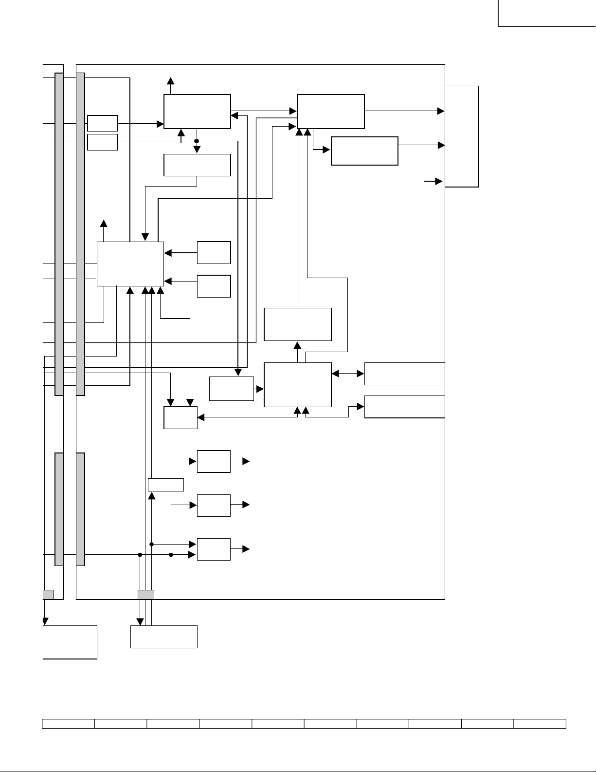
LC-20B4M
03
SC2002
FILTER
FL801
FILTER
FL802
I2C
VIDEO
DECODER CONTROLLER
)
(VPC
LCD
(DPS)
IC801 IC1201
REV
V2V0
SYNC SEP IC1101
IC802
R0~7,G0~7,B0~7 PANEL
V0,V7,V21
V64,V112
GRADATION
POWER
V176 ,V235
V255
VCOM
CSCOM
LCD
CSYNC
OSD R/G/B
VLS,VGL,VEE
I2C GSP1,VSH
GBLR,GCK
POWER
E2PROM
MICON
IC2001
RXD,TXD
1
IC2010
RESET
IC2006
TEXT
R/G/B
TEXT R/G/B
AMP
Q1602,Q1604,Q1606
TX_FB
GSP2
P35 02
CONTROL
RECEIVER
P701
Q2002
KEY1
KEY2
POW1 POW2
P2001
SW UNITREMOTE
SWITCH
IC2003
VIDEO SW
IC1604
RX_TX,TX_RX
3.3V REG
3.3V
IC705
3.3V REG
3.3V
IC707
5V REG 5V
IC2004
TELETEXT SRAM 2M
CPU IC1612
IC1601 FLASH 4M
IC1611
25
1716 1918151413121110
Page 26

LC-20B4M
OVERALL WIRING DIA GRAM
H
G
F
E
D
C
B
A
87109654321
26
Page 27

LC-20B4M
27
1716 1918151413121110
Page 28

LC-20B4M
DESCRIPTION OF SCHEMATIC DIAGRAM
VOLTAGE MEASUREMENT CONDITION:
1. The voltages at test points are measured on
exclusive AC adaptor and the stable supply voltage
of AC 120V. Signals are fed by a color bar signal
generator for servicing purpose and the above
voltages are measured with a 20k ohm/V tester.
INDICATION OF RESISTOR & CAPACITOR:
RESISTOR
1. The unit of resistance “Ω” is omitted.
(K=kΩ=1000 Ω, M=MΩ).
2. All resistors are ± 5%, unless otherwise noted.
(J= ± 5%, F= ± 1%, D= ± 0.5%)
3. All resistors are 1/16W, unless otherwise noted.
4. All resistors are Carbon type, unless otherwise
noted.
C
: Solid
S : Oxide Film T : Special
N : Metal Coating
CAPACITOR
1. All capacitors are µF, unless otherwise noted.
(P=pF=µµF).
2. All capacitors are 50V, unless otherwise noted.
3. All capacitors are Ceramic type, unless otherwise
noted.
(ML): Mylar (TA): Tantalum
(PF): Polypro Film (ST): Styrol
W
: Cement
CAUTION:
This circuit diagram is original one, therefore there may be a
slight difference from yours.
IMPORTANT SAFETY NOTICE:
PARTS MARKED WITH “å” ( ) ARE
IMPORTANT FOR MAINTAINING THE SAFETY OF
THE SET. BE SURE TO REPLACE THESE PARTS
WITH SPECIFIED ONES FOR MAINTAINING THE
SAFETY AND PERFORMANCE OF THE SET.
28
Page 29

SCHEMATIC DIAGRAM
Ë
R/C, LED and OPERATION Unit
H
G
F
LC-20B4M
E
D
C
B
A
654321
29
Page 30

LC-20B4M
Ë
MAIN Unit-1/7
H
G
F
E
D
C
B
A
87109654321
30
Page 31

LC-20B4M
31
1716 1918151413121110
Page 32

LC-20B4M
Ë
MAIN Unit-2/7
H
G
F
E
D
C
B
A
87109654321
32
Page 33

LC-20B4M
33
1716 1918151413121110
Page 34

LC-20B4M
Ë
MAIN Unit-3/7
H
G
F
E
D
C
B
A
87109654321
34
Page 35

LC-20B4M
35
1716 1918151413121110
Page 36

LC-20B4M
Ë
MAIN Unit-4/7
H
G
F
E
D
C
B
A
87109654321
36
Page 37

LC-20B4M
37
1716 1918151413121110
Page 38

LC-20B4M
Ë
MAIN Unit-5/7
H
G
F
E
D
C
B
A
87109654321
38
Page 39

LC-20B4M
39
1716 1918151413121110
Page 40

LC-20B4M
Ë
MAIN Unit-6/7
H
G
F
E
D
C
B
A
87109654321
40
Page 41

LC-20B4M
41
1716 1918151413121110
Page 42

LC-20B4M
Ë
MAIN Unit-7/7
H
G
F
E
D
C
B
A
87109654321
42
Page 43

LC-20B4M
43
1716 1918151413121110
Page 44

LC-20B4M
Ë
TUNER Unit-1/4 (LC-20B4M)
H
G
F
E
D
C
B
A
87109654321
44
Page 45

LC-20B4M
45
1716 1918151413121110
Page 46

LC-20B4M
Ë
TUNER Unit-1/4 (LC-20B4M(X))
H
G
F
E
D
C
B
A
87109654321
46
Page 47

LC-20B4M
47
1716 1918151413121110
Page 48

LC-20B4M
Ë
TUNER Unit-2/4
H
G
F
E
D
C
B
A
87109654321
48
Page 49

LC-20B4M
49
1716 1918151413121110
Page 50

LC-20B4M
Ë
TUNER Unit-3/4
H
G
F
E
D
C
B
A
87109654321
50
Page 51

LC-20B4M
51
1716 1918151413121110
Page 52

LC-20B4M
Ë
TUNER Unit-4/4
H
G
F
E
D
C
B
A
87109654321
52
Page 53

LC-20B4M
53
1716 1918151413121110
Page 54

LC-20B4M
Ë
INVERTER-A Unit
H
G
F
E
D
C
B
A
654321
54
Page 55

LC-20B4M
Ë
INVERTER-B Unit
H
G
F
E
D
C
B
A
654321
55
Page 56

LC-20B4M
PRINTED WIRING BOARD ASSEMBLIES
H
G
F
E
D
C
B
A
MAIN Unit (Side-A)
654321
56
Page 57

LC-20B4M
H
R1237
C1221
C1222
C1223
C1224
C1227 C1228
C1234
C1225
C1226
R1238
R1239
C1229 C1230 C1231 C1232 C1233
C1204
C1205 C1206 C1207
L1204
L1207
L1206
C1236
C1245
C1244
R1213
R1214
C1247
C1246
C726
R1217
R1210
C1237
L1205
R1216
C707
IC702
R1234
IC1201
R1215
R1260
R1240
R1218
C1102
R1241
R1242
R1219
C1235
R1101
R1235
R1212
C1104
C1101
C1105
C1208
R1220
R1232
C1220
R1228
C1218
C1217
C1215
R1227
R1226
R1225
C1213
R1224
R1223C1212
R1221
X1201
R1211
C1243
IC1101
C1107
C1109
C1108
C1605
SC1203
FB1201
C1210
R1222
C1209
R1122
R1120
SC1202
R1116
R1121
D1104
C1106
C1110
R1102
R1103
R1236
R7003
C853
R7004
C854
C855
R847
C857
C856
R1259
R1233
R1231
R1258
C1219
R1229
C1216
R1261
R1262
C1214
C1211
D708 R710
C711
C722
C715
TP2041
C845
R837
R841
R836 C851 C852
X801
C843
G
F
E
C829
C833
P701
R831
R838
R832 R833
C874
C875
C873
C838
C847
C836
R874
R873
C835
L807
R875
L806
IC805
L808
R827
C872
C822
C826 FL801
C837
IC703
C708
L701
R839
C848
C820
R840
C849
C819
C840
IC801
C850
Q702
C719
C720
SC1204
R842
L805
C818
L804
R713
R843
R711
R844
R845
C844
C846
FL802
C724
C703
D709
C702
D
R2071
C2027
Q2004
R2063
R2067
R2060
R2058
C
R2057
R2036 R2044
R2049
R2009
R2008
Q2001
R2011
R2013
R2029
R2026
R2024
B
TP2040
R2074
R2046
R2081
R2082
IC2001
R2042
R2037
R2033
R2030 R2027
R2025 R2023
R2020 R2019
SC2002
R2083
R2021
R2022
R2094
R2086
R2100
R2105
R2088
R2101
R2095
R2084
C2012
R2039
R2076
R2089
R2034
R2092
R2001
Q703
R2002
R2077
R2069
C2023
R2091
R2059
R2068
R2052
R2050
R2103
R2102
R2078
R2073
R2066
C2002
D2002
R2061
X2001
D2003
R2010
R2017
IC2010
C2026
C2020
C2029
IC2004
R2016 C2005
C2007
R1664
C1645
R1613
Q1608
C1615
R1647
IC1616
R1632
R1629
R1630
R1646
R1637
R1663
R1661
C1607
C1628
C1630
R1628
R1631
C1633
C1634
R1662
C1613
R1660
C1609
C1620
C1601
R1639
C1122
C1603
R1659
FB1601
FB1602
C1604
IC1607
C1612
C1652 C1651
FB1607
R1626
C1627
IC1601
R1638
R1645
R1641
R1640
C1643
C1602
R1601
C1608
C1606 C1611
FB1604
C1614
C1618
FB1608
C1629
R1633
R1634
C1631
FB1609
R1635
C1635
C1637
C1638
C1639
X1601
R1642
IC1605
C1640
C1641
IC1602
C1623
C1617
R2006
C1622
P2001
FDC001
A
MAIN Unit (Chip Parts Side-A)
57
654321
Page 58

LC-20B4M
H
G
F
E
D
C
B
A
MAIN Unit (Side-B)
654321
58
Page 59

LC-20B4M
H
TL1225
TL1290
TL1224
R1245
Q1205
R1243C1239
R1248
D1203
R1119
C1642
R1651
C1647
C1650
R1652
R1654
Q1209
C1118
C1113
R1627
Q1208
R1124
D1101
R1254
Q1210
D1102Q1104
D1201R1249
R1251
R1255
C1119
R1109
Q1207
R1247
D1202
D1204
Q1211
R1244
R1128R1125
R1127R1126
C1241
D1206
D1205
Q1204
R1123
D1103
Q1101
R1108
C1644
C1649
Q1206
R1246
R1256
R1252
C1117
R1253
Q1106
R1118
R1113
R1117
R7006
R859
IC803
C813
R822
Q806R878
R813R823
R862
R718
R1114
Q1105
R1104
C1111
C712
C713
IC704
C725
R717
D712
R1112
C1116
C1616
C1621
IC1604
R1603
R1621
IC1612
IC1611
Q1607
Q1605
L1601
Q1606
R1657
FB1603
R1617
R1615
R1612
R1611
R1604
R1622
R1614
R1609
R1610R1616
C1610
Q1603
Q1604
R1619
R1624
R1620
R1618
C1619
R816
D713
D714
R1608
Q803
C709
C705
C812
R716
Q1601
R1656
R2056
R1605
R1623
R2075
R2065
R1665
R2032
R858
D710
R715
C717
R2072
R1602
R1606
R1607
C809
R860
L702R877
C723
D701
Q2003
C2025
Q1602
TL1282
TL1281
TL1280
TL1256
TL1243
TL1234
TL1233
TL1232
TL1286
TL1231
TL1277
TL1273
TL1270
TL1267
TL1265
TL1259
TL1254
TL1248
TL1287
TL1245
TL1242
TL1241
TL1202
TL1240
TL1201
TL1239
TL1238
TL1237
TL1236
TL1235
TL1278
TL1274
TL1266
TL1261
TL1285
TL1289
TL1269
TL1262
TL1258
TL1257
TL1253
TL1250
TL1249
TL1246
TL1288
C1115
C1242
R1250
C1238
IC1202
C1240
R1107
C1112
Q1103
R1106
R1110
C1114
R1111
R1115
R1105
Q1102
TL1279
TL1276
TL1275
G
TL1272
TL1271
TL1268
TL1264
TL1263
TL1260
TL1255
TL1252
TL1251
TL1247
TL1244
F
E
D
TL1602
C
B
FDC002
TL2037
TL2039
TL2038
TL2040
C1636
IC1609
TL2001
R1636
FB1610
R1643
FB1611
R1644
R1648
TL1601
C1632
C1624
R1653
IC1606IC1603
C1625
FB1605
R1625C1626
IC1610
IC1614
IC1615
FB1606
TL1603
R1658
IC1608
TL1223
D707
D706
C718
IC2009
TL1222
R835
R805
R702
R703
R701
R2043Q2002
IC2006
C2018
R1655
TL2002
TL1221
R876
C863
TL803
R853
Q701
IC701
C714
TL701
R2070
TL2042
TL2003
TL1220
TL1219
TL1283
R849
C864
C701R709
C710
C728
R2062
TL2056
R2047
TL2055
TL2004
TL2043
TL1218
TL1208
TL1206
C804
C858
C862
R854
R708
R707
IC705
IC707
C727
IC2008
R2051C2022
R2064
TL2006
TL2005
C866
R855
D704
R2097
TL2007
TL1217
TL1216
TL1207
TL1205
R871
R804
C803
C859
R856
C716
D711
D703
C704
TL2008
TL2009
TL2045
TL2044
TL1215
TL1214
R861
C871
R850
R857
R714
R2085
C2028
R2099
TL2010
TL2011
TL1213
R818
C860
R712
C721
C2024
D2001
R2007
TL2012
TL2015
TL2013
TL1211
TL1212
Q804R817
R806
C867
IC2011
TL2014
TL2019
TL2017
TL1209
TL1210
C814
IC808
IC806
R851
C869
C868
IC706
R706
D702
TL2060
R2090R2087
Q2007
R2079
IC2007
TL2016
TL2018
TL2023
TL2021
IC802
C861
R872IC807
R2098
TL2020
TL2022
C810
R815
C815
R824
R852
C706
R704
Q2006
TL2059
R2093
R2096
Q2005
TL2054
R2015
TL2024
TL2025
TL2035
R863
R864
C824
R2045
C2008
TL2053
R2012
C2001
R2004
TL2026
TL2033
TL2027
R809
R807
C807
C801
C802
C805
R865
TL2058
R2080
R2014
TL2028
TL2029
TL2046
C808
C806
C831
C870
R870
Q808
TL709
TL708
TL707
TL706
TL705
TL704
TL703
TL702
IC2005
TL2057
C2003
C2006
TL2030
TL2031
C834
R2104
R811
C830
R830
C821
C823
C828
R829
IC2003
TL2032
TL2034
R812
R820
C832
TL801
TL711
TL713
TL710
TL712
P702
R2041
R2055
C2004
TL2036
A
MAIN Unit (Chip Parts Side-B)
59
654321
Page 60

LC-20B4M
H
G
R/C, LED Unit (Side-A)
P4004
D4022
D4012
D4015
R4021
C4018
SLD4001
RMC4002
R4024
R4029
D4014
Q4003
R4023
Q4007
R4001
Q4001
D4011
F
R/C, LED Unit (Chip Parts Side-A)
E
D
OPERATION Unit (Side-A)
(QPWBSB770WJN2)
C
B
P4001
S4701
D4010
D4009
D4008
SW4006
SW4004
R4012
SW4003
R4011
SW4002
SW4007
R4005 R4006
SW4008
OPERATION Unit (Chip Parts Side-A)
(QPWBSB770WJN2)
A
654321
60
Page 61

LC-20B4M
H
G
F
E
D
C
B
A
TUNER Unit (Side-A)
654321
61
Page 62

LC-20B4M
5
4
0
2
7
2
7
7
R
R
R
3
C3347
C3367
C3209
C3368
R3318
R3314
R3317
R3302
C3311
R3321
C3313
R3378
R3329
C3318
R3370
C3206
R3319
C3309
C3377
C3335
TP3701
IC3305
R3322
R3368
IC3302
C3362
C3365
R3364
C3370
C3361
C3364
C3360
C3371
C3308
R3390
R3315
R3517
Q3305
R3366
R3365
Q3304
R3216
Q3205
R3381
R3379
R3363
P3502
R3518
FH3702
R3360
R3361
C3366
R3519
C3202
R3203
C3203
C3359
C3305
R3310
R3358
R3312
R3343
Q3204
R3311
D3301
R3306
C3302
R3304
R3380
C3306
R3382
C3304
Q3203
L3201
D3302
R3383
R3346
R3399
IC3301
R3309
C3387
R3386
R3316 R3303
R3201 C3201
R3202
Q3306
R3313 C3301
C3363
R3307
C3303 C3389 R3388
R3204
R3205
C3388
R3387
FH3701
Q3201
R3362
C3386
R3389
C3385
R3305
R3308
C3333
Q3202
C3024
R3206
C3405
C3406
C3734
D3711
C3717
C3735
R3755
L3202
R3753
L3701
R3752
R3751
C3307
C3713
R3749
R3746
R3747
R3744
IC3702
Q3708
C3404
IC3401
R3748 R3750
Q3709
C3733
C3403
C3730
Q3707
R3737
C3729
R3745
R3734
R3731
C3722
C3731
R3719
R3732
C3714
R3722
R3725
C3402
R3754
C3732
R3707
R3521
P
R37
R3738 R3740
Q3
R37
D3701
Q3701
C37
L3
FB3
D37
FB
D370
C3501
H
J3701
P3604
FH3704
P3603
Q3601
FH3703
G
TU3201
F
R3331
R3333
R3334
IC3303
C3337
C3369
R3327
R3522
R3757
R3328
R3324
C3312
R3320
C3310
C3321
C3205
C3334
C3315
C3376
R3377
R3326
C3316
R3209
C3322 C3210
R3217
R3214
C3372
Q3212
C3375
C3336 R3323
R3215 R3213
R3332
C3319
R3325
R3376
R3330
R3375
C3374
C3317
R3369 C3314
R3208
C3320
C3323
C3338
E
R3520
R3371
R3385
R3372
R3410
R3411
R3211 C3211
R3373
C3378
R3413
R3409
Q3211
R3210
R3212
C3379
R3384
C3401 R3207
R3412
J3303
D
P3501
SC3405
C
B
A
J3407
R3338
R3401
R3335
R3339
R3336
R3337
D3401
R3402
C3324
R3340
C3325
C3350
62
C3339
C3340
C3341
C3342
C3343
C3344
C3345
C3346
C3349
C3373
C3348
R3356
L3301
C3351
C3354
C3352
C3355
C3356
C3357
R3357
C3358
L3302
IC3304
X3301
C3330
R3354
R3353
R3355 C3382
SC3403
R3611
C3332
TP3702
87109654321
Page 63

LC-20B4M
R3755
C3735
C
3734
R3753
L3701
R3752
R3751
C3307
C3713
R3749
R3746
R3747
R3744
IC3702
R3748 R3750
Q3708
Q3709
C3733
C3730
Q3707
R3737
C3729
R3745
R3734
R3731
C3722
C3731
R3719
R3732
C3714
R3722
R3725
R3754
C3732
R3707
R3521
R3742
R3738 R3740
Q3705
R3723
C3727
L3702
FB3703
D3706
FB3702
D3705
P3701
R3743
R3741
R3728
D3701
Q3701
R3739
C3702
C3712
R3701
R3735
C3736
R3703
Q3704
R3708
FB3709
C3711
C3706
Q3702
R3702
R3713
Q3703
D3702
C3716
R3705
C3703
C3721
P3301
R3717
R3718
C3710
Q3706
R3712
C3708
T3701
C3701
R3758
R3729
R3603
R3609
R3704
C3718
D3707
D3709
C3605
R3756
R3606
R3715
R3714
C3724
C3707
L3703
L8402
C3723
P3602
D3603
Q3604
C3607
R3716
R3710
C3608
R3604
D3606
R3736
C3719
D3604
L3704
C3726
C3609
C3737
C3610
R3607
Q3605
C3728
L8401
R3602
D3602
P8401
R3601
C3601
R3610
Q3602
R3608
C8464
P3302
D3710
D3703
IC3701
FB3705
R3761
R3765
R3724
C3738
R3762 R3760
D3704
FB3701
C3606
FB3708
R3709
R3759
C3705
C3715
FB3707
D3609 Q3603
R3706
C3704
R3515
R3514
C3709
R3711
D3607
D3608
C3602
C8434
R3605
C3329
C8463
D3601
D3605 Q3606
R3349
P3601
Q8456
R3347
R8467
C8461
C3603
C3604
C3328
R8456
R3348
C8433
R8468
C8462
R8461 R8459
R8454
Q8451
C8451
R3352
Q8455
R8465
C8459
Q8453
C8458
C8455
C8453 C8457
R8462
C8454
R8453
C3781
R8466
Q8454
C8452
R3433
R8452
R8451
R3430
R3351
R3350
R3431
C8460
R8464
R8463
R3428
R8458
R8457
C8456
R3429
R8455 R8460
J3409
R3432
J3404
Q8452
L3202
C3404
IC3401
C3403
C3402
C3501
C3208
R3516
IC3502
C3502
C3503
R3564
R3547
C3519
R3540
R3528
R3526
C3517
Q3505
R3560
R3534
R3537
C3512
L3500
C3510
C3515
R3533
IC3501
C3514
Q3504
C3518
R3524
Q3501
R3542
C3509
R3529
R3525
R3559
R3527
R3536
Q3503
R3535
Q3502
R3523
R3538
C3516
R3539
R3563
C3520
C3395
C3521
C3394
C3513
R3562
R3545
R3561
Q3510
Q3511
Q3512
R3544
R3552 R3543
C3522
D3501
R3531
R3554
R3530
C3511
D3502 R3556
R3553
R3557
D3402
R3455
R3344
R3341
R3555 R3342
Q3513
R3558
R3532
R3345
J3408
TUNER Unit (Chip Parts Side-A)
1716 1918151413121110
63
Page 64

LC-20B4M
H
G
F
E
D
C
B
A
INVERTER-A Unit (Side-A)
654321
64
Page 65

LC-20B4M
H
FH6704
R6708
R6722
Q6708
R6711
C6713
R6727
D6700
R6726
R6725
FH6702
FH6703
FH6701 FH6700
R6710
L6704
C6714
R6707 C6708
C6709
FH6705
G
P6705
F
C6712
R6709
R6706
R6721
Q6705
R6705
C6707
R6704
Q6706
Q6707
Q6704
Q6703
T6705
C6727
C6726
T6704
L6702
T6703
FDC4
P6702
E
P6701
T6702
D
C6704
R6703 R6702
C6703
Q6702
R6720
L6700
C6702
R6701
Q6701
R6700
Q6700
C6725
C
P6700
T6701
B
T6700
FDC1
A
INVERTER-A Unit (Chip Parts Side-A)
65
654321
Page 66

LC-20B4M
H
G
F
E
D
C
INVERTER-B Unit (Side-A)
B
A
654321
66
Page 67

LC-20B4M
H
G
T6709
C6741
F
Q6712
Q6713
C6722
R6716
R6717
E
R6719
R6718
C6723
FH6708
D
Q6714 R6724
C6724
Q6709
C6740
Q6710
L6708
T6707
T6708
P6704
P6703
FH6709
R6712
R6723
Q6711
R6714
R6713
C6717
L6706
R6729
R6728
D6701
C
P6706
C6719
R6715 C6718
FH6707 FH6706
T6706
INVERTER-B Unit (Chip Parts Side-A)
B
A
654321
67
Page 68

LC-20B4M
Ref. No. Part No. ★ Description Code Ref. No. Part No. ★ Description Code
PARTS LIST
PARTS REPLACEMENT
Replacement parts which have these special safety characteristics
identified in this manual; electrical components having such f eatures
are identified by å and shaded areas in the Replacement P arts Lists
and Schematic Diagrams. The use of a substitute replacement part
which does no have the same safety characteristic as the factory
recommended replacement parts shown in this service manual may
create shock, fire or other hazards.
"HOW TO ORDER REPLACEMENT PARTS"
To have your order filled promptly and correctly, please fur nish the
following informations.
1. MODEL NUMBER 2. REF. NO.
3. PART NO. 4. DESCRIPTION
★ MARK: SPARE PARTS-DELIVERY SECTION
Ref. No. Part No. ★ Description Code
PRINTED WIRING BOARD ASSEMBLIES
(NOT REPLACEMENT ITEM)
LC-20B4M
DUNTKB750FE06 – MAIN Unit —
DUNTKB768DE09 – TUNER Unit —
DUNTKB769DE09 – R/C, LED Unit —
DUNTKB770DE09 – OPERATION Unit —
DUNTKB590DE02 – INVERTER-A Unit —
DUNTKB591DE02 – INVERTER-B Unit —
LC-20B4M(X)
DUNTKB750FE06 – MAIN Unit —
DUNTKB768DE12 – TUNER Unit —
DUNTKB769DE12 – R/C, LED Unit —
DUNTKB770DE12 – OPERATION Unit —
DUNTKB590DE02 – INVERTER-A Unit —
DUNTKB591DE02 – INVERTER-B Unit —
LCD PANEL
NOTE: THE PARTS HERE SHOWN ARE SUPPLIED AS AN
ASSEMBLY BUT NOT INDEPENDENTLY.
RLCDTA014WJN1 J 20" LCD Panel Unit DM
DUNTKB750FE06
MAIN UNIT
INTEGRATED CIRCUITS
IC701 VSUMX2N++++-1Y J UMX2N AB
IC702 VHiNJU7662M-1Y J NJU7662M(TE2) AL
IC703 VHiNJ79M08D-1Y J NJM79M08DL1A AF
IC704 VHiPQ1R33//-1Y J PQ1R33 AE
IC705 VHiPQ1R34++-1Y J PQ1R34 AE
IC706 VHiLM1117MJ-1Y J LM1117MPX-ADJ AF
IC707 VHiMM1573DN-1Y J MM1573DNRE AD
IC801 VHiVPC3230D1EQ J VPC3230D-QA-B3 BD
IC802 VHiBA7046F/-1Y J BA7046F AF
IC805 VHiMM1563DF-1Y J MM1563DFBE AE
IC1101 VHiBD8120FP-1Y J BD8120FP AX
IC1201 VHiDPS9450+-1Q J DPS9450A-XZ-A1 BD
IC1202 VHiTC4W66U/-1Y J TC4W66FU AE
IC1601 VHiSDA5550M-1Q J SDA5550M AZ
IC1602 VHiBA05FP++-1Y J BA05FP-E2 AF
IC1603 VHiPST3228N1EY J PST3228NR AB
IC1604 VHiMM1501XN-1Y J MM1501XNRE AE
IC1605 VHiMM1562FF-1Y J MM1562FFBE AE
IC1606 VHiPST3221N1EY J PST3221NR AB
IC1607 VHiMM1563DF-1Y J MM1563DFBE AE
IC1608 VHiNC7SZ58P-1Y J NC7SZ58P6X AE
IC1609 VHiTC7SZ08U-1Y J TC7SZ08FU AE
IC1610 VHiLCX157MT-1Y J 74LCX157MTCX AE
IC1611 RH-iXA388WJZZQ J MBM29DL400TC90 AY
IC1612 VHi62S8308X-1Q J A62S8308X-70SI AY
IC1614 VHiVHC08MTC1EY J 74VHC08MTCX AD
IC1615 VHi74LVX86M-1Y J 74LVX86MTCX AD
IC2001 RH-iXA640WJZZQ J M306V3MG-105FP BA
IC2003 VHiMM1573DN-1Y J MM1573DNRE AD
IC2004 VHiPQ1L503M-1Y J PQ1L503M2SP AD
IC2005 VHiBU4052FV-1Y J BU4052BCFV-E2 AE
IC2006 VHiBD4729G+-1Y J BD4729G-TR AD
IC2009 VHiTC4W66U/-1Y J TC4W66FU AE
IC2010 VHiBR2416E2-1Y J BR24C16F AK
IC2011 VHiTC4W66U/-1Y J TC4W66FU AE
TRANSISTORS
Q701 VS2SA1037KQ-1Y J 2SA1037KQ AA
Q702 VSFMMT718//-1Y J FMMT718 AE
Q703 VSDTC144EE/-1Y J DTC144EE AA
Q803 VS2SA1530AR-1Y J 2SA1530AR AB
Q804 VS2SA1530AR-1Y J 2SA1530AR AB
Q806 VS2SA1530AR-1Y J 2SA1530AR AB
Q1101 VSFMMT718//-1Y J FMMT718 AE
Q1102 VS2SC4520//-1Y J 2SC4520 AE
Q1103 VS2SA1729//-1Y J 2SA1729 AF
Q1104 VSDTC144EE/-1Y J DTC144EE AA
Q1105 VS2SC4520//-1Y J 2SC4520 AE
Q1106 VS2SA1729//-1Y J 2SA1729 AF
Q1204 VSDTC144EE/-1Y J DTC144EE AA
Q1601 VS2SA1530AR-1Y J 2SA1530AR AB
Q1602 VS2SA1530AR-1Y J 2SA1530AR AB
Q1603 VSDTC144TE/-1Y J DTC144TE AB
Q1604 VS2SA1530AR-1Y J 2SA1530AR AB
Q1605 VS2SC3928AR-1Y J 2SC3928AR AB
Q1606 VS2SA1530AR-1Y J 2SA1530AR AB
Q1607 VS2SA1530AR-1Y J 2SA1530AR AB
Q2001 VSUM5K1NTR+-1Y J UM5K1NTR AC
Q2002 VSDTC114EE/-1Y J DTC144EE AB
Q2003 VSUPA606T//-1Y J UPA606T AD
Q2005 VSUPA606T//-1Y J UPA606T AD
Q2006 VSDTC114EE/-1Y J DTC144EE AB
Q2007 VSUPA606T//-1Y J UPA606T AD
D701 RH-EX1247CEZZY J Zener Diode, 5.6V AB
D702 VHDDAN222//-1Y J Diode AA
D703 RH-EX1245CEZZY J Zener Diode, 5.1V AB
D704 VHDDAN222//-1Y J Diode AA
D706 VHDDAN222//-1Y J Diode AA
68
DIODES
Page 69

LC-20B4M
Ref. No. Part No. ★ Description Code Ref. No. Part No. ★ Description Code
DUNTKB750FE06
MAIN UNIT (Continued)
D707 VHDDAN222//-1Y J Diode AA
D708 RH-EX1245CEZZY J Zener Diode, 5.1V AB
D709 VHDDAN222//-1Y J Diode AA
D710 VHD1SS250//1EY J Diode AB
D711 VHDDAN202K/-1Y J Diode AB
D712 VHDDAN222//-1Y J Diode AA
D713 VHDRB481K++-1Y J Diode AD
D714 VHDRB491D++-1Y J Diode AD
D1101 VHD1SS250//1EY J Diode AB
D1102 VHDDAN222//-1Y J Diode AA
D1103 VHD1SS250//1EY J Diode AB
D1104 VHD1SS250//1EY J Diode AB
D2001 RH-EX1232CEZZY J Zener Diode AB
D2002 VHDDAN202K/-1Y J Diode AB
D2003 VHDDAN202K/-1Y J Diode AB
PACKAGED CIRCUITS
X801 RCRSC0012CEZZY J Crystal, 20.25MHz AH
X1201 RCRSC0012CEZZY J Crystal, 20.25MHz AH
X1601 RCRSCA002WJZZY J Crystal AG
FILTER AND COILS
X2001 RFiLZ0169TAZZY J Filter AD
FL801 RCiLFA033WJZZY J Coil AG
FL802 RCiLFA033WJZZY J Coil AG
L701 RCiLPA143WJZZY J Coil AD
L702 VP-1M470J5R4NY J Peaking 47µH AC
L804 RCiLPA143WJZZY J Coil AD
L805 RCiLPA143WJZZY J Coil AD
L806 VP-9N3R3KR46NY J Peaking 3.3µH AC
L807 VP-9N3R3KR46NY J Peaking 3.3µH AC
L808 VP-9N3R3KR46NY J Peaking 3.3µH AC
L1204 VPCGM220M0R5NY J Peaking 22µH AB
L1205 VPCGM220M0R5NY J Peaking 22µH AB
L1206 VPCGM220M0R5NY J Peaking 22µH AB
L1207 VPCGM220M0R5NY J Peaking 22µH AB
L1601 VP-1M270J3R8NY J Peaking 27µH AC
CAPACITORS
C701 VCKYCY1EF104ZY J 0.1 25V Ceramic AA
C702 VCEASK1CN227MY J 220 16V Electrolytic AC
C703 RC-EZA123WJZZY J 100 6.3V Electrolytic AC
C704 VCKYTV1CB105KY J 1 16V Ceramic AC
C705 VCKYTV1CB105KY J 1 16V Ceramic AC
C706 RC-KZ0075TAZZY J 2.2 16V Ceramic AC
C707 RC-KZA041WJZZY J 10 10V Ceramic AC
C708 RC-EZA129WJZZY J 2.2 50V Electrolytic AB
C709 VCKYTV1CB105KY J 1 16V Ceramic AC
C710 VCKYTV1CB105KY J 1 16V Ceramic AC
C711 RC-EZA132WJZZY J 10 50V Electrolytic AC
C712 RC-KZA041WJZZY J 10 10V Ceramic AC
C713 RC-KZA041WJZZY J 10 10V Ceramic AC
C714 RC-KZA041WJZZY J 10 10V Ceramic AC
C715 RC-EZA132WJZZY J 10 50V Electrolytic AC
C716 RC-KZA041WJZZY J 10 10V Ceramic AC
C717 VCKYTV1CB105KY J 1 16V Ceramic AC
C718 RC-KZA041WJZZY J 10 10V Ceramic AC
C719 RC-EZA123WJZZY J 100 6.3V Electrolytic AC
C720 VCEASH0JN227MY J 220 6.3V Electrolytic AC
C721 VCKYCY1EF104ZY J 0.1 25V Ceramic AA
C722 RC-EZA131WJZZY J 4.7 50V Electrolytic AC
C723 VCKYCY1EF104ZY J 0.1 25V Ceramic AA
C724 RC-EZA132WJZZY J 10 50V Electrolytic AC
C725 VCKYCY1EF104ZY J 0.1 25V Ceramic AA
C726 RC-EZA132WJZZY J 10 50V Electrolytic AC
C727 VCKYTV1CB105KY J 1 16V Ceramic AC
C728 VCKYCY1HF103ZY J 0.01 50V Ceramic AA
C806 VCKYCY1AB105KY J 1 10V Ceramic AB
C807 VCKYCY1HB222KY J 2200p 50V Ceramic AA
C808 VCCCCY1HH101JY J 100p 50V Ceramic AA
C810 VCKYCY1EF104ZY J 0.1 25V Ceramic AA
C814 VCKYCY1AB105KY J 1 10V Ceramic AB
C815 VCKYCY1HB102KY J 1000p 50V Ceramic AA
C818 RC-EZA135WJZZY J 4.7 6.3V Electrolytic AC
C819 VCKYCY1EF104ZY J 0.1 25V Ceramic AA
C820 RC-EZA122WJZZY J 22 6.3V Electrolytic AB
C821 VCKYTV1CF684ZY J 0.68 16V Ceramic AB
C822 RC-KZA030WJZZY J 2.2 10V Ceramic AB
C823 VCKYTV1CF684ZY J 0.68 16V Ceramic AB
C824 VCKYCY1EF104ZY J 0.1 25V Ceramic AA
C826 RC-EZA123WJZZY J 100 6.3V Electrolytic AC
C828 RC-KZ1025CEZZY J 1 10V Ceramic AB
C829 RC-EZA123WJZZY J 100 6.3V Electrolytic AC
C830 VCKYCY1EF104ZY J 0.1 25V Ceramic AA
C831 RC-KZ1025CEZZY J 1 10V Ceramic AB
C832 VCKYCY1EF104ZY J 0.1 25V Ceramic AA
C833 RC-EZA123WJZZY J 100 6.3V Electrolytic AC
C834 VCKYTV1CF684ZY J 0.68 16V Ceramic AB
C835 VCKYCY1HB331KY J 330p 50V Ceramic AA
C836 VCKYCY1HB331KY J 330p 50V Ceramic AA
C837 RC-EZA124WJZZY J 10 16V Electrolytic AB
C838 VCKYCY1HB331KY J 330p 50V Ceramic AA
C840 VCKYCY1EF104ZY J 0.1 25V Ceramic AA
C843 VCCCCY1HH7R0DY J 7p 50V Ceramic AA
C844 VCKYCY1EF104ZY J 0.1 25V Ceramic AA
C845 VCCCCY1HH7R0DY J 7p 50V Ceramic AA
C846 RC-EZA134WJZZY J 220 6.3V Electrolytic AC
C847 VCKYCY1CF224ZY J 0.22 16V Ceramic AB
C848 VCKYCY1CF224ZY J 0.22 16V Ceramic AB
C849 VCKYCY1CF224ZY J 0.22 16V Ceramic AB
C850 RC-KZ0117TAZZY J 4.7 6.3V Ceramic AD
C851 RC-KZ1025CEZZY J 1 10V Ceramic AB
C852 RC-KZ1025CEZZY J 1 10V Ceramic AB
C853 VCKYCY1EF104ZY J 0.1 25V Ceramic AA
C854 VCKYCY1EF104ZY J 0.1 25V Ceramic AA
C855 RC-KZ1025CEZZY J 1 10V Ceramic AB
C856 RC-KZ1025CEZZY J 1 10V Ceramic AB
C857 VCKYCY1EF104ZY J 0.1 25V Ceramic AA
C863 VCKYCY1EF104ZY J 0.1 25V Ceramic AA
C867 VCKYCY1EB473KY J 0.047 25V Ceramic AA
C868 VCKYCY1EB473KY J 0.047 25V Ceramic AA
C869 VCKYCY1EB473KY J 0.047 25V Ceramic AA
C872 VCCCCY1HH471JY J 470p 50V Ceramic AA
C873 VCKYCY1AB224KY J 0.22 10V Ceramic AB
C874 VCKYCY1AB224KY J 0.22 10V Ceramic AB
C875 VCKYCY1AB224KY J 0.22 10V Ceramic AB
C1101 VCKYCY1EF104ZY J 0.1 25V Ceramic AA
C1102 RC-EZ1339CEZZY J 220 16V Electrolytic AD
C1104 VCKYCY1EF104ZY J 0.1 25V Ceramic AA
C1105 VCCCCY1HH181JY J 180p 50V Ceramic AA
C1106 VCKYCY1EF104ZY J 0.1 25V Ceramic AA
C1107 RC-KZA041WJZZY J 10 10V Ceramic AC
C1108 VCCCCY1HH560JY J 56p 50V Ceramic AB
C1109 RC-KZA041WJZZY J 10 10V Ceramic AC
C1110 VCKYCY1EF104ZY J 0.1 25V Ceramic AA
C1111 VCKYCY1EF104ZY J 0.1 25V Ceramic AA
C1112 VCKYCY1HB103KY J 0.01 50V Ceramic AA
C1113 VCKYCY1HB103KY J 0.01 50V Ceramic AA
C1114 VCCCCY1HH560JY J 56p 50V Ceramic AB
C1115 VCKYTV1CB334KY J 0.33 16V Ceramic AC
C1116 VCKYTV1CB105KY J 1 16V Ceramic AC
C1117 VCKYTV1CB105KY J 1 16V Ceramic AC
C1118 VCKYCY1EB104KY J 0.1 25V Ceramic AB
C1119 RC-KZA041WJZZY J 10 10V Ceramic AC
C1122 RC-EZ1339CEZZY J 220 16V Electrolytic AD
C1204 VCKYCY1EF104ZY J 0.1 25V Ceramic AA
C1205 VCKYCY1EF104ZY J 0.1 25V Ceramic AA
C1206 VCKYCY1EF104ZY J 0.1 25V Ceramic AA
C1207 VCKYCY1EF104ZY J 0.1 25V Ceramic AA
C1208 VCKYCY1EF104ZY J 0.1 25V Ceramic AA
C1209 VCCCCY1HH7R0DY J 7p 50V Ceramic AA
C1210 VCCCCY1HH7R0DY J 7p 50V Ceramic AA
C1211 VCKYCY1EF104ZY J 0.1 25V Ceramic AA
C1212 VCKYCY1EF104ZY J 0.1 25V Ceramic AA
C1213 VCKYCY1EF104ZY J 0.1 25V Ceramic AA
C1214 VCKYCY1EF104ZY J 0.1 25V Ceramic AA
69
Page 70

LC-20B4M
Ref. No. Part No. ★ Description Code Ref. No. Part No. ★ Description Code
DUNTKB750FE06
MAIN UNIT (Continued)
C1215 VCKYCY1EF104ZY J 0.1 25V Ceramic AA
C1216 VCKYCY1EF104ZY J 0.1 25V Ceramic AA
C1217 VCKYCY1EF104ZY J 0.1 25V Ceramic AA
C1218 VCKYCY1EF104ZY J 0.1 25V Ceramic AA
C1219 VCKYCY1EF104ZY J 0.1 25V Ceramic AA
C1220 VCKYCY1EF104ZY J 0.1 25V Ceramic AA
C1221 VCKYCY1CF474ZY J 0.47 16V Ceramic AB
C1222 VCKYCY1CF474ZY J 0.47 16V Ceramic AB
C1223 VCKYCY1CF474ZY J 0.47 16V Ceramic AB
C1224 VCKYCY1CF474ZY J 0.47 16V Ceramic AB
C1225 VCKYCY1CF474ZY J 0.47 16V Ceramic AB
C1226 VCKYCY1CF474ZY J 0.47 16V Ceramic AB
C1227 VCKYCY1EF104ZY J 0.1 25V Ceramic AA
C1228 VCKYCY1EF104ZY J 0.1 25V Ceramic AA
C1229 VCKYCY1EF104ZY J 0.1 25V Ceramic AA
C1230 VCKYCY1EF104ZY J 0.1 25V Ceramic AA
C1231 VCKYCY1EF104ZY J 0.1 25V Ceramic AA
C1232 VCKYCY1EF104ZY J 0.1 25V Ceramic AA
C1233 VCKYCY1EF104ZY J 0.1 25V Ceramic AA
C1234 RC-EZA143WJZZY J 100 6.3V Electrolytic AC
C1235 RC-EZA143WJZZY J 100 6.3V Electrolytic AC
C1236 VCKYCY1EF104ZY J 0.1 25V Ceramic AA
C1237 VCKYCY1EF104ZY J 0.1 25V Ceramic AA
C1238 VCKYCY1EF104ZY J 0.1 25V Ceramic AA
C1240 VCCCCY1HH220JY J 22p 50V Ceramic AA
C1244 VCKYCY1EF104ZY J 0.1 25V Ceramic AA
C1245 VCKYCY1EF104ZY J 0.1 25V Ceramic AA
C1246 RC-EZA143WJZZY J 100 6.3V Electrolytic AC
C1247 RC-EZA143WJZZY J 100 6.3V Electrolytic AC
C1601 RC-KZ0074TAZZY J 10 6.3V Ceramic AF
C1602 VCKYCY1EF104ZY J 0.1 25V Ceramic AA
C1603 VCKYCY1EF104ZY J 0.1 25V Ceramic AA
C1604 VCKYCY1CF334ZY J 0.33 16V Ceramic AB
C1605 RC-EZA127WJZZY J 100 6.3V Electrolytic AC
C1606 RC-EZA123WJZZY J 100 6.3V Electrolytic AC
C1607 RC-EZA199WJZZY J 10 25V Electrolytic AC
C1608 VCKYCY1EF104ZY J 0.1 25V Ceramic AA
C1609 RC-EZA123WJZZY J 100 6.3V Electrolytic AC
C1610 VCKYCY1HB103KY J 0.01 50V Ceramic AA
C1611 RC-EZA123WJZZY J 100 6.3V Electrolytic AC
C1612 RC-KZA030WJZZY J 2.2 10V Ceramic AB
C1613 VCE9PF0JN226MY J 22 6.3V Elect. (N.P) AD
C1614 VCKYCY1CF334ZY J 0.33 16V Ceramic AB
C1615 RC-EZA125WJZZY J 2.2 16V Electrolytic AC
C1616 VCKYCY1HB103KY J 0.01 50V Ceramic AA
C1617 RC-EZA135WJZZY J 4.7 6.3V Electrolytic AC
C1618 RC-KZA030WJZZY J 2.2 10V Ceramic AB
C1619 VCCCCY1HH181JY J 180p 50V Ceramic AA
C1620 VCE9PF0JN226MY J 22 6.3V Elect. (N.P) AD
C1622 RC-EZA122WJZZY J 22 6.3V Electrolytic AB
C1623 RC-EZA135WJZZY J 4.7 6.3V Electrolytic AC
C1624 VCKYCY1EF104ZY J 0.1 25V Ceramic AA
C1625 VCKYCY1EF104ZY J 0.1 25V Ceramic AA
C1626 VCKYCY1EF104ZY J 0.1 25V Ceramic AA
C1627 VCKYCY1EF104ZY J 0.1 25V Ceramic AA
C1628 VCKYCY1EF104ZY J 0.1 25V Ceramic AA
C1629 VCKYCY1EF104ZY J 0.1 25V Ceramic AA
C1630 VCKYCY1EF104ZY J 0.1 25V Ceramic AA
C1631 VCKYCY1EF104ZY J 0.1 25V Ceramic AA
C1632 VCKYCY1EF104ZY J 0.1 25V Ceramic AA
C1633 VCKYTV1CF105ZY J 1 16V Ceramic AB
C1634 VCKYCY1EF104ZY J 0.1 25V Ceramic AA
C1636 VCKYCY1EF104ZY J 0.1 25V Ceramic AA
C1639 VCKYCY1EF104ZY J 0.1 25V Ceramic AA
C1640 VCCCCY1HH330JY J 33p 50V Ceramic AA
C1641 VCCCCY1HH330JY J 33p 50V Ceramic AA
C1642 VCKYCY1EF104ZY J 0.1 25V Ceramic AA
C1643 VCKYCY1EF104ZY J 0.1 25V Ceramic AA
C1644 RC-KZ0074TAZZY J 10 6.3V Ceramic AF
C1647 VCKYCY1EF104ZY J 0.1 25V Ceramic AA
C1649 VCKYCY1EF104ZY J 0.1 25V Ceramic AA
C1650 VCKYCY1EF104ZY J 0.1 25V Ceramic AA
C1651 VCCCCY1HH471JY J 470p 50V Ceramic AA
C1652 VCCCCY1HH471JY J 470p 50V Ceramic AA
C2002 VCKYTV1CF105ZY J 1 16V Ceramic AB
C2003 RC-KZ0074TAZZY J 10 6.3V Ceramic AF
C2004 VCKYCY1EF104ZY J 0.1 25V Ceramic AA
C2005 VCKYCY1EF104ZY J 0.1 25V Ceramic AA
C2006 VCKYCY1AB105KY J 1 10V Ceramic AB
C2007 RC-EZA122WJZZY J 22 6.3V Electrolytic AB
C2008 VCKYCY1EF104ZY J 0.1 25V Ceramic AA
C2012 VCKYCY1EF104ZY J 0.1 25V Ceramic AA
C2018 VCKYTV1CF684ZY J 0.68 16V Ceramic AB
C2020 RC-EZA124WJZZY J 10 16V Electrolytic AB
C2022 VCKYCY1EF104ZY J 0.1 25V Ceramic AA
C2023 VCKYCY1EF104ZY J 0.1 25V Ceramic AA
C2025 VCKYCY1EF104ZY J 0.1 25V Ceramic AA
C2026 VCKYCY1EF104ZY J 0.1 25V Ceramic AA
C2027 VCKYCY1EF104ZY J 0.1 25V Ceramic AA
C2028 VCKYCY1EF104ZY J 0.1 25V Ceramic AA
C2029 VCKYCY1EF104ZY J 0.1 25V Ceramic AA
RESISTORS
R701 VRS-CY1JF000JY J 0 1/16W Metal Oxide AA
R702 VRS-CY1JF682JY J 6.8k 1/16W Metal Oxide AA
R703 VRS-CY1JF562JY J 5.6k 1/16W Metal Oxide AA
R704 VRS-CY1JF1R0JY J 1 1/16W Metal Oxide AA
R707 VRS-CY1JF103JY J 10k 1/16W Metal Oxide AA
R708 VRS-CY1JF272JY J 2.7k 1/16W Metal Oxide AA
R709 VRS-CY1JF272JY J 2.7k 1/16W Metal Oxide AA
R710 VRS-CY1JF102JY J 1k 1/16W Metal Oxide AA
R711 VRS-CY1JF103JY J 10k 1/16W Metal Oxide AA
R712 VRS-CY1JF680FY J 68 1/16W Metal Oxide AA
R713 VRS-CY1JF272JY J 2.7k 1/16W Metal Oxide AA
R714 VRS-CY1JF151FY J 150 1/16W Metal Oxide AA
R715 VRS-TX2HF330JY J 33 1/2W Metal Oxide AB
R716 VRS-TV1JD562JY J 5.6k 1/10W Metal Oxide AA
R717 VRS-TW2ED150JY J 15 1/4W Metal Oxide AA
R718 VRS-TX2HF472JY J 4.7k 1/2W Metal Oxide AB
R804 VRS-CY1JF000JY J 0 1/16W Metal Oxide AA
R805 VRS-CY1JF561FY J 560 1/16W Metal Oxide AA
R807 VRS-CY1JF103JY J 10k 1/16W Metal Oxide AA
R809 VRS-CY1JF474JY J 470k 1/16W Metal Oxide AA
R811 VRS-CY1JF104JY J 100k 1/16W Metal Oxide AA
R812 VRS-CY1JF333JY J 33k 1/16W Metal Oxide AA
R813 VRS-CY1JF152JY J 1.5k 1/16W Metal Oxide AA
R815 VRS-CY1JF152JY J 1.5k 1/16W Metal Oxide AA
R816 VRS-CY1JF000JY J 0 1/16W Metal Oxide AA
R817 VRS-CY1JF152JY J 1.5k 1/16W Metal Oxide AA
R818 VRS-CY1JF103JY J 10k 1/16W Metal Oxide AA
R820 VRS-CY1JF152JY J 1.5k 1/16W Metal Oxide AA
R822 VRS-CY1JF152JY J 1.5k 1/16W Metal Oxide AA
R823 VRS-CY1JF152JY J 1.5k 1/16W Metal Oxide AA
R824 VRS-CY1JF152JY J 1.5k 1/16W Metal Oxide AA
R827 VRS-CY1JF000JY J 0 1/16W Metal Oxide AA
R829 VRS-CY1JF102JY J 1k 1/16W Metal Oxide AA
R830 VRS-CY1JF000JY J 0 1/16W Metal Oxide AA
R836 VRS-CY1JF000JY J 0 1/16W Metal Oxide AA
R837 VRS-CY1JF000JY J 0 1/16W Metal Oxide AA
R838 VRS-CY1JF102JY J 1k 1/16W Metal Oxide AA
R839 VRS-CY1JF102JY J 1k 1/16W Metal Oxide AA
R840 VRS-CY1JF102JY J 1k 1/16W Metal Oxide AA
R841 VRS-CA1JF101JY J 100 1/16W Metal Oxide AA
R842 VRS-CA1JF101JY J 100 1/16W Metal Oxide AA
R843 VRS-CY1JF101JY J 100 1/16W Metal Oxide AA
R845 VRS-CY1JF101JY J 100 1/16W Metal Oxide AA
R847 VRS-CA1JF220JY J 22 1/16W Metal Oxide AA
R849 VRS-CY1JF102FY J 1k 1/16W Metal Oxide AA
R854 VRS-CY1JF000JY J 0 1/16W Metal Oxide AA
R856 VRS-CY1JF392FY J 3.9k 1/16W Metal Oxide AA
R858 VRS-CY1JF561FY J 560 1/16W Metal Oxide AA
R859 VRS-CY1JF561FY J 560 1/16W Metal Oxide AA
R860 VRS-CY1JF561FY J 560 1/16W Metal Oxide AA
R870 VRS-CY1JF000JY J 0 1/16W Metal Oxide AA
R871 VRS-CY1JF000JY J 0 1/16W Metal Oxide AA
R872 VRS-CB1JF000JY J 0 1/16W Metal Oxide AC
70
Page 71

LC-20B4M
Ref. No. Part No. ★ Description Code Ref. No. Part No. ★ Description Code
DUNTKB750FE06
MAIN UNIT (Continued)
R873 VRS-CY1JF750JY J 75 1/16W Metal Oxide AA
R874 VRS-CY1JF750JY J 75 1/16W Metal Oxide AA
R875 VRS-CY1JF750JY J 75 1/16W Metal Oxide AA
R1101 VRS-CY1JF273FY J 27k 1/16W Metal Oxide AA
R1102 VRS-CY1JF472FY J 4.7k 1/16W Metal Oxide AA
R1103 VRS-CY1JF472FY J 4.7k 1/16W Metal Oxide AA
R1104 VRS-CY1JF472JY J 4.7k 1/16W Metal Oxide AA
R1105 VRS-CY1JF391JY J 390 1/16W Metal Oxide AA
R1106 VRS-CY1JF102JY J 1k 1/16W Metal Oxide AA
R1107 VRS-CY1JF391JY J 390 1/16W Metal Oxide AA
R1108 VRS-TW2ED102JY J 1k 1/4W Metal Oxide AA
R1109 VRS-TW2ED5R6JY J 5.6 1/4W Metal Oxide AA
R1110 VRS-TW2ED8R2JY J 8.2 1/4W Metal Oxide AA
R1111 VRS-CY1JF103FY J 10k 1/16W Metal Oxide AA
R1112 VRS-CY1JF181JY J 180 1/16W Metal Oxide AA
R1113 VRS-CY1JF102JY J 1k 1/16W Metal Oxide AA
R1114 VRS-CY1JF181JY J 180 1/16W Metal Oxide AA
R1115 VRS-TX2HF100JY J 10 1/2W Metal Oxide AB
R1117 VRS-TX2HF5R6JY J 5.6 1/2W Metal Oxide AB
R1118 VRS-TX2HF5R6JY J 5.6 1/2W Metal Oxide AB
R1119 VRS-CY1JF473JY J 47k 1/16W Metal Oxide AA
R1121 VRS-CY1JF000JY J 0 1/16W Metal Oxide AA
R1122 VRS-CY1JF000JY J 0 1/16W Metal Oxide AA
R1123 VRS-TX2HF000JY J 0 1/2W Metal Oxide AB
R1124 VRS-TX2HF101JY J 100 1/2W Metal Oxide AA
R1126 VRS-CY1JF000JY J 0 1/16W Metal Oxide AA
R1128 VRS-CY1JF000JY J 0 1/16W Metal Oxide AA
R1210 VRS-CY1JF101JY J 100 1/16W Metal Oxide AA
R1211 VRS-CY1JF101JY J 100 1/16W Metal Oxide AA
R1212 VRS-CA1JF101JY J 100 1/16W Metal Oxide AA
R1213 VRS-CY1JF101JY J 100 1/16W Metal Oxide AA
R1216 VRS-CA1JF101JY J 100 1/16W Metal Oxide AA
R1217 VRS-CB1JF101JY J 100 1/16W Metal Oxide AA
R1218 VRS-CA1JF101JY J 100 1/16W Metal Oxide AA
R1219 VRS-CA1JF101JY J 100 1/16W Metal Oxide AA
R1220 VRS-CA1JF101JY J 100 1/16W Metal Oxide AA
R1221 VRS-CY1JF000JY J 0 1/16W Metal Oxide AA
R1222 VRS-CY1JF105JY J 1M 1/16W Metal Oxide AA
R1223 VRS-CY1JF000JY J 0 1/16W Metal Oxide AA
R1224 VRS-CY1JF101JY J 100 1/16W Metal Oxide AA
R1225 VRS-CY1JF680JY J 68 1/16W Metal Oxide AA
R1226 VRS-CY1JF220JY J 22 1/16W Metal Oxide AA
R1227 VRK-CD1JJ220JY J 22 1/16W Metal Compo. AC
R1228 VRK-CD1JJ220JY J 22 1/16W Metal Compo. AC
R1229 VRS-CY1JF101JY J 100 1/16W Metal Oxide AA
R1231 VRS-CY1JF223JY J 22k 1/16W Metal Oxide AA
R1232 VRK-CD1JJ220JY J 22 1/16W Metal Compo. AC
R1233 VRS-CY1JF101JY J 100 1/16W Metal Oxide AA
R1234 VRS-CA1JF101JY J 100 1/16W Metal Oxide AA
R1235 VRS-CA1JF220JY J 22 1/16W Metal Oxide AA
R1236 VRS-CY1JF101JY J 100 1/16W Metal Oxide AA
R1237 VRS-CY1JF102JY J 1k 1/16W Metal Oxide AA
R1238 VRS-CY1JF220JY J 22 1/16W Metal Oxide AA
R1239 VRS-CY1JF221JY J 220 1/16W Metal Oxide AA
R1240 VRS-CY1JF101JY J 100 1/16W Metal Oxide AA
R1242 VRS-CY1JF101JY J 100 1/16W Metal Oxide AA
R1244 VRS-CY1JF472JY J 4.7k 1/16W Metal Oxide AA
R1251 VRS-CY1JF000JY J 0 1/16W Metal Oxide AA
R1258 VRS-CY1JF101JY J 100 1/16W Metal Oxide AA
R1259 VRS-CY1JF182JY J 1.8k 1/16W Metal Oxide AA
R1260 VRS-CY1JF000JY J 0 1/16W Metal Oxide AA
R1262 VRS-CY1JF101JY J 100 1/16W Metal Oxide AA
R1601 VRS-TX2HF2R2JY J 2.2 1/2W Metal Oxide AB
R1602 VRS-CY1JF152JY J 1.5k 1/16W Metal Oxide AA
R1603 VRS-CY1JF101JY J 100 1/16W Metal Oxide AA
R1604 VRS-CY1JF101JY J 100 1/16W Metal Oxide AA
R1605 VRS-CY1JF101JY J 100 1/16W Metal Oxide AA
R1607 VRS-CY1JF391FY J 390 1/16W Metal Oxide AA
R1608 VRS-CY1JF332JY J 3.3k 1/16W Metal Oxide AA
R1609 VRS-CY1JF681JY J 680 1/16W Metal Oxide AA
R1610 VRS-CY1JF391FY J 390 1/16W Metal Oxide AA
R1611 VRS-CY1JF132JY J 1.3k 1/16W Metal Oxide AG
R1612 VRS-CY1JF000JY J 0 1/16W Metal Oxide AA
R1614 VRS-CY1JF223JY J 22k 1/16W Metal Oxide AA
R1615 VRS-CY1JF223JY J 22k 1/16W Metal Oxide AA
R1616 VRS-CY1JF391FY J 390 1/16W Metal Oxide AA
R1617 VRS-CY1JF102JY J 1k 1/16W Metal Oxide AA
R1618 VRS-CY1JF102FY J 1k 1/16W Metal Oxide AA
R1619 VRS-CY1JF102FY J 1k 1/16W Metal Oxide AA
R1620 VRS-CY1JF681FY J 680 1/16W Metal Oxide AA
R1621 VRS-CY1JF102JY J 1k 1/16W Metal Oxide AA
R1622 VRS-CY1JF102JY J 1k 1/16W Metal Oxide AA
R1623 VRS-CY1JF102JY J 1k 1/16W Metal Oxide AA
R1624 VRS-CY1JF681FY J 680 1/16W Metal Oxide AA
R1625 VRS-CY1JF223JY J 22k 1/16W Metal Oxide AA
R1627 VRS-CY1JF333JY J 33k 1/16W Metal Oxide AA
R1628 VRS-CY1JF332JY J 3.3k 1/16W Metal Oxide AA
R1629 VRS-CY1JF332JY J 3.3k 1/16W Metal Oxide AA
R1631 VRS-CY1JF222JY J 2.2k 1/16W Metal Oxide AA
R1632 VRS-CB1JF332JY J 3.3k 1/16W Metal Oxide AC
R1635 VRS-CY1JF221JY J 220 1/16W Metal Oxide AA
R1637 VRS-CY1JF221JY J 220 1/16W Metal Oxide AA
R1639 VRS-CY1JF000JY J 0 1/16W Metal Oxide AA
R1642 VRS-CY1JF000JY J 0 1/16W Metal Oxide AA
R1645 VRS-CA1JF221JY J 220 1/16W Metal Oxide AC
R1647 VRS-CY1JF333JY J 33k 1/16W Metal Oxide AA
R1655 VRS-CY1JF102FY J 1k 1/16W Metal Oxide AA
R1656 VRS-CY1JF102FY J 1k 1/16W Metal Oxide AA
R1657 VRS-CY1JF102FY J 1k 1/16W Metal Oxide AA
R1659 VRS-CY1JF000JY J 0 1/16W Metal Oxide AA
R1661 VRS-CY1JF221JY J 220 1/16W Metal Oxide AA
R1664 VRS-CY1JF000JY J 0 1/16W Metal Oxide AA
R1665 VRS-CY1JF332JY J 3.3k 1/16W Metal Oxide AA
R2001 VRS-CY1JF000JY J 0 1/16W Metal Oxide AA
R2002 VRS-CY1JF000JY J 0 1/16W Metal Oxide AA
R2006 VRS-CY1JF1R0JY J 1 1/16W Metal Oxide AA
R2007 VRS-CY1JF101JY J 100 1/16W Metal Oxide AA
R2008 VRS-CY1JF223JY J 22k 1/16W Metal Oxide AA
R2009 VRS-CY1JF223JY J 22k 1/16W Metal Oxide AA
R2010 VRS-CY1JF1R0JY J 1 1/16W Metal Oxide AA
R2011 VRS-CY1JF393JY J 39k 1/16W Metal Oxide AA
R2012 VRS-CY1JF000JY J 0 1/16W Metal Oxide AA
R2013 VRS-CY1JF333JY J 33k 1/16W Metal Oxide AA
R2014 VRS-CY1JF000JY J 0 1/16W Metal Oxide AA
R2015 VRS-CY1JF000JY J 0 1/16W Metal Oxide AA
R2017 VRS-CY1JF103JY J 10k 1/16W Metal Oxide AA
R2019 VRS-CY1JF101JY J 100 1/16W Metal Oxide AA
R2020 VRS-CY1JF101JY J 100 1/16W Metal Oxide AA
R2021 VRS-CA1JF102JY J 1k 1/16W Metal Oxide AA
R2022 VRS-CA1JF223JY J 22k 1/16W Metal Oxide AA
R2024 VRS-CY1JF103JY J 10k 1/16W Metal Oxide AA
R2026 VRS-CY1JF223JY J 22k 1/16W Metal Oxide AA
R2029 VRS-CA1JF223JY J 22k 1/16W Metal Oxide AA
R2032 VRS-CY1JF000JY J 0 1/16W Metal Oxide AA
R2033 VRS-CY1JF103JY J 10k 1/16W Metal Oxide AA
R2034 VRS-CY1JF512JY J 5.1k 1/16W Metal Oxide AA
R2036 VRS-CY1JF102JY J 1k 1/16W Metal Oxide AA
R2037 VRS-CY1JF103JY J 10k 1/16W Metal Oxide AA
R2039 VRS-CY1JF512JY J 5.1k 1/16W Metal Oxide AA
R2041 VRS-CY1JF103JY J 10k 1/16W Metal Oxide AA
R2042 VRS-CY1JF101JY J 100 1/16W Metal Oxide AA
R2043 VRS-CY1JF153JY J 15k 1/16W Metal Oxide AA
R2044 VRS-CY1JF101JY J 100 1/16W Metal Oxide AA
R2045 VRS-CY1JF103JY J 10k 1/16W Metal Oxide AA
R2046 VRS-CY1JF101JY J 100 1/16W Metal Oxide AA
R2047 VRS-CY1JF223JY J 22k 1/16W Metal Oxide AA
R2049 VRS-CA1JF101JY J 100 1/16W Metal Oxide AA
R2050 VRS-CY1JF102JY J 1k 1/16W Metal Oxide AA
R2051 VRS-CY1JF223JY J 22k 1/16W Metal Oxide AA
R2052 VRS-CY1JF512JY J 5.1k 1/16W Metal Oxide AA
R2055 VRS-CB1JF101JY J 100 1/16W Metal Oxide AA
R2056 VRS-CA1JF103JY J 10k 1/16W Metal Oxide AA
R2057 VRS-CA1JF101JY J 100 1/16W Metal Oxide AA
R2058 VRS-CY1JF101JY J 100 1/16W Metal Oxide AA
R2060 VRS-CA1JF101JY J 100 1/16W Metal Oxide AA
R2063 VRS-CY1JF223JY J 22k 1/16W Metal Oxide AA
71
Page 72

LC-20B4M
Ref. No. Part No. ★ Description Code Ref. No. Part No. ★ Description Code
DUNTKB750FE06
MAIN UNIT (Continued)
R2064 VRS-CY1JF103JY J 10k 1/16W Metal Oxide AA
R2065 VRS-CY1JF103JY J 10k 1/16W Metal Oxide AA
R2066 VRS-CA1JF101JY J 100 1/16W Metal Oxide AA
R2067 VRS-CY1JF223JY J 22k 1/16W Metal Oxide AA
R2068 VRS-CY1JF101JY J 100 1/16W Metal Oxide AA
R2069 VRS-CY1JF000JY J 0 1/16W Metal Oxide AA
R2070 VRS-CY1JF472JY J 4.7k 1/16W Metal Oxide AA
R2071 VRS-CY1JF101JY J 100 1/16W Metal Oxide AA
R2072 VRS-CY1JF472JY J 4.7k 1/16W Metal Oxide AA
R2073 VRS-CA1JF153JY J 15k 1/16W Metal Oxide AB
R2074 VRS-CY1JF101JY J 100 1/16W Metal Oxide AA
R2076 VRS-CB1JF101JY J 100 1/16W Metal Oxide AA
R2077 VRS-CA1JF101JY J 100 1/16W Metal Oxide AA
R2078 VRS-CA1JF101JY J 100 1/16W Metal Oxide AA
R2079 VRS-CY1JF472JY J 4.7k 1/16W Metal Oxide AA
R2080 VRS-CY1JF472JY J 4.7k 1/16W Metal Oxide AA
R2081 VRS-CY1JF101JY J 100 1/16W Metal Oxide AA
R2082 VRS-CY1JF101JY J 100 1/16W Metal Oxide AA
R2083 VRS-CY1JF101JY J 100 1/16W Metal Oxide AA
R2084 VRS-CY1JF101JY J 100 1/16W Metal Oxide AA
R2085 VRS-CY1JF223JY J 22k 1/16W Metal Oxide AA
R2086 VRS-CA1JF101JY J 100 1/16W Metal Oxide AA
R2087 VRS-CY1JF472JY J 4.7k 1/16W Metal Oxide AA
R2088 VRS-CY1JF393JY J 39k 1/16W Metal Oxide AA
R2089 VRS-CY1JF101JY J 100 1/16W Metal Oxide AA
R2090 VRS-CY1JF472JY J 4.7k 1/16W Metal Oxide AA
R2091 VRS-CY1JF101JY J 100 1/16W Metal Oxide AA
R2092 VRS-CY1JF101JY J 100 1/16W Metal Oxide AA
R2093 VRS-CA1JF103JY J 10k 1/16W Metal Oxide AA
R2096 VRS-CA1JF103JY J 10k 1/16W Metal Oxide AA
R2097 VRS-CY1JF101JY J 100 1/16W Metal Oxide AA
R2098 VRS-CY1JF512JY J 5.1k 1/16W Metal Oxide AA
R2099 VRS-CY1JF101JY J 100 1/16W Metal Oxide AA
R2100 VRS-CY1JF512JY J 5.1k 1/16W Metal Oxide AA
R2101 VRS-CY1JF512JY J 5.1k 1/16W Metal Oxide AA
R2102 VRS-CY1JF512JY J 5.1k 1/16W Metal Oxide AA
R2103 VRS-CY1JF512JY J 5.1k 1/16W Metal Oxide AA
R2104 VRS-CY1JF103JY J 10k 1/16W Metal Oxide AA
R2105 VRS-CY1JF000JY J 0 1/16W Metal Oxide AA
R7003 VRS-CB1JF000JY J 0 1/16W Metal Oxide AC
R7004 VRS-CB1JF000JY J 0 1/16W Metal Oxide AC
R7006 VRS-CA1JF000JY J 0 1/16W Metal Oxide AB
MISCELLANEOUS PARTS
FB1201 RBLN-0083GEZZY J Ferrite Bead AB
FB1601 RBLN-0006TAZZY J Ferrite Bead AB
FB1602 RBLN-0006TAZZY J Ferrite Bead AB
FB1603 RBLN-0006TAZZY J Ferrite Bead AB
FB1604 RBLN-0006TAZZY J Ferrite Bead AB
FB1605 RBLN-0006TAZZY J Ferrite Bead AB
FB1606 RBLN-0006TAZZY J Ferrite Bead AB
FB1607 RBLN-0076TAZZY J Ferrite Bead AC
FB1608 RBLN-0076TAZZY J Ferrite Bead AC
FB1609 RBLN-0076TAZZY J Ferrite Bead AC
FB1610 RBLN-0076TAZZY J Ferrite Bead AC
FB1611 RBLN-0076TAZZY J Ferrite Bead AC
P701 QPLGN0549FJZZY J Plug, 12-pin(MB) AE
P702 QPLGN0274TAZZY J Plug, 2-pin AC
P2001 QPLGN0558REZZY J Plug, 5-pin(MS) AE
SC1202 QSOCNA002WJPZY J Socket, 20-pin(LK) AD
SC1203 QSOCN0687FJZZY J Socket, 50-pin(LS) AF
SC1204 QSOCN0206FJZZY J Socket, 30-pin(LG) AF
SC2002 QSOCN0464FJZZY J Socket, 50-pin(MA) AH
TP2040 QLUGHA002WJZZ J Lug AB
DUNTKB768FE09 (LC-20B4M)
DUNTKB768FE12 (LC-20B4M(X))
TUNER UNIT
TUNER
NOTE: THE PARTS HERE SHOWN ARE SUPPLIED AS AN
ASSEMBLY BUT NOT INDEPENDENTLY.
TU3201 VTUVT2U5CD553 J Tuner (LC-20B4M) BD
TU3201 VTUVT2U5CD558 J Tuner (LC-20B4M(X)) BF
INTEGRATED CIRCUITS
IC3301 VHiNJM4560M-1Y J NJM4560M AG
IC3302 VHiNJM4560M-1Y J NJM4560M AG
IC3303 VHiNJM4560M-1Y J NJM4560M AG
IC3304 RH-iX1853BMZZQ J MSP3410G-QG-B8 BB
IC3305 VHiLA4635A+-1S J LA4635A AM
IC3401 VHiNJM2293M-1Y J NJM2293M(TE1) AG
IC3501 VHiTC4053BF1EY J TC4053BF AF
IC3502 VHiNJM2268M-1Y J NJM2268M-TE1 AF
IC3701 VHiNJM2377M-1Y J NJM2377M AK
IC3702 VHiNJM2147M-1Y J NJM2147M-TE1 AF
TRANSISTORS
Q3201 VS2SC3928AR-1Y J 2SC3928AR AB
Q3202 VS2SC3928AR-1Y J 2SC3928AR AB
Q3203 VSDTC144EE/-1Y J DTC144EE AA
Q3204 VSDTC144EE/-1Y J DTC144EE AA
Q3205 VSDTC144EE/-1Y J DTC144EE AA
Q3211 VSiMZ1A////-1Y J IMZ1A AC
Q3212 VSiMZ1A////-1Y J IMZ1A AC
Q3304 VSDTC314TK/-1Y J DTC314TK AC
Q3305 VSDTC314TK/-1Y J DTC314TK AC
Q3501 VSUMG4N++++-1Y J UMG4N AB
Q3502 VSUPA1970++-1Y J UPA1970 AE
Q3503 VS2SC3928AR-1Y J 2SC3928AR AB
Q3504 VS2SC3928AR-1Y J 2SC3928AR AB
Q3505 VSDTC114EE/-1Y J DTC114EE AB
Q3510 VSDTC314TK/-1Y J DTC314TK AC
Q3511 VSDTC314TK/-1Y J DTC314TK AC
Q3512 VS2SA1037KQ-1Y J 2SA1037KQ AA
Q3513 VS2SC2712Y/-1Y J 2SC2712Y AB
Q3601 VSDTC144EE/-1Y J DTC144EE AA
Q3602 VSUM5K1NTR+-1Y J UM5K1NTR AC
Q3603 VSUM5K1NTR+-1Y J UM5K1NTR AC
Q3604 VSUM5K1NTR+-1Y J UM5K1NTR AC
Q3605 VSUM5K1NTR+-1Y J UM5K1NTR AC
Q3606 VSUM5K1NTR+-1Y J UM5K1NTR AC
Q3701 VSDTC144EE/-1Y J DTC144EE AA
Q3702 VSFMMT718//-1Y J FMMT718 AE
Q3703 VSFMMT718//-1Y J FMMT718 AE
Q3704 VSDTC144EE/-1Y J DTC144EE AA
Q3705 VSFMY3/////-1Y J FMY3 AB
Q3706 VS2SK2503//-1Y J 2SK2503 AE
Q3707 VSFMMT619//-1Y J FMMT619 AE
Q3708 VS2SC3928AR-1Y J 2SC3928AR AB
Q3709 VSFMY3/////-1Y J FMY3 AB
DIODES
D3302 VHDDAN222//-1Y J Diode AA
D3401 RH-EX1271CEZZY J Zener Diode, 12V AB
D3402 RH-EX1271CEZZY J Zener Diode, 12V AB
D3501 VHDDAN222//-1Y J Diode AA
D3502 RH-EX1396CEZZY J Zener Diode, 6.8V AB
D3601 VHDiMN10///-1Y J Diode AB
D3602 VHDDAN222//-1Y J Diode AA
D3603 VHDiMN10///-1Y J Diode AB
D3604 VHDiMN10///-1Y J Diode AB
D3605 VHDDAN222//-1Y J Diode AA
D3606 VHDDAN222//-1Y J Diode AA
D3607 VHDDAN222//-1Y J Diode AA
D3608 VHDDAN222//-1Y J Diode AA
D3609 VHDDAN222//-1Y J Diode AA
D3701 VHDDAN222//-1Y J Diode AA
D3702 VHDDAN222//-1Y J Diode AA
D3705 VHDSFPB56//2EY J Diode AC
72
Page 73

LC-20B4M
Ref. No. Part No. ★ Description Code Ref. No. Part No. ★ Description Code
DUNTKB768FE09 (LC-20B4M)
DUNTKB768FE12 (LC-20B4M(X))
TUNER UNIT (Continued)
D3706 VHDSFPB74//2EY J Diode AD
D3707 VHDSFPB74//2EY J Diode AD
D3709 VHDDAN222//-1Y J Diode AA
D3710 VHD1SS250//1EY J Diode AB
D3711 VHDDAN222//-1Y J Diode AA
PACKAGED CIRCUITS
X3301 RCRSB0307CEZZ J Crystal AG
COILS
L3201 VP-1M220J2R9NY J Peaking 22µH AB
L3202 RCiLPA142WJZZ J Coil AD
L3301 VP-1M101J7R7NY J Peaking 100µH AC
L3302 VP-1M4R7J1R2NY J Peaking 4.7µH AB
L3500 VP-1M101J7R7NY J Peaking 100µH AC
L3701 RCiLPA026WJZZ J Coil AD
L3702 RCiLPA144WJZZY J Coil AD
L3703 RCiLPA143WJZZY J Coil AD
L3704 RCiLPA026WJZZ J Coil AD
TRANSFORMER
å T3701 RTRNWA090WJZZY J Transformer AH
CONTROL
R3714 RVR-M0111CEZZY J 1k(B) B+Adj. AC
CAPACITORS
C3024 VCKYCY1EF104ZY J 0.1 25V Ceramic AA
C3201 VCKYCY1HB102KY J 1000p 50V Ceramic AA
C3202 VCCCCY1HH330JY J 33p 50V Ceramic AA
C3203 VCCCCY1HH330JY J 33p 50V Ceramic AA
C3205 VCKYCY1EF104ZY J 0.1 25V Ceramic AA
C3206 VCKYCY1HF103ZY J 0.01 50V Ceramic AA
C3208 RC-EZA085WJZZ J 3300 10V Electrolytic AE
C3209 RC-EZA128WJZZY J 1 50V Electrolytic AB
C3210 VCKYCY1EF104ZY J 0.1 25V Ceramic AA
C3211 VCKYCY1EF104ZY J 0.1 25V Ceramic AA
C3301 VCKYCY1HB392KY J 3900p 50V Ceramic AA
C3302 VCKYCY1HB392KY J 3900p 50V Ceramic AA
C3303 VCKYCY1EB822KY J 8200p 25V Ceramic AA
C3304 VCKYCY1HB392KY J 3900p 50V Ceramic AA
C3305 VCKYCY1HB392KY J 3900p 50V Ceramic AA
C3306 VCKYCY1HB822KY J 8200p 50V Ceramic AB
C3307 VCEASH1CN337MY J 330 16V Electrolytic AE
C3308 VCKYCY1EF104ZY J 0.1 25V Ceramic AA
C3309 VCKYCY1HB682KY J 6800p 50V Ceramic AA
C3310 VCKYCY1HB682KY J 6800p 50V Ceramic AA
C3311 VCKYCY1EB153KY J 0.015 25V Ceramic AA
C3312 VCKYCY1EB153KY J 0.015 25V Ceramic AA
C3313 VCKYCY1HB682KY J 6800p 50V Ceramic AA
C3314 VCKYCY1HB682KY J 6800p 50V Ceramic AA
C3315 VCKYCY1EF104ZY J 0.1 25V Ceramic AA
C3316 VCKYCY1CB273KY J 0.027 16V Ceramic AB
C3317 VCKYCY1CB273KY J 0.027 16V Ceramic AB
C3318 VCKYCY1CB273KY J 0.027 16V Ceramic AB
C3319 VCKYCY1CB273KY J 0.027 16V Ceramic AB
C3320 RC-EZA126WJZZY J 47 16V Electrolytic AC
C3321 RC-EZA129WJZZY J 2.2 50V Electrolytic AB
C3322 RC-EZA129WJZZY J 2.2 50V Electrolytic AB
C3323 VCKYCY1EF104ZY J 0.1 25V Ceramic AA
C3324 RC-EZA129WJZZY J 2.2 50V Electrolytic AB
C3325 RC-EZA129WJZZY J 2.2 50V Electrolytic AB
C3328 RC-EZA129WJZZY J 2.2 50V Electrolytic AB
C3329 RC-EZA129WJZZY J 2.2 50V Electrolytic AB
C3330 VCKYCY1EF104ZY J 0.1 25V Ceramic AA
C3332 RC-EZA127WJZZY J 100 16V Electrolytic AC
C3333 RC-EZA127WJZZY J 100 16V Electrolytic AC
C3334 VCKYCY1EF104ZY J 0.1 25V Ceramic AA
C3335 VCKYCY1HB222KY J 2200p 50V Ceramic AA
C3336 VCKYCY1HB222KY J 2200p 50V Ceramic AA
C3337 RC-KZA041WJZZY J 10 10V Ceramic AC
C3338 RC-KZA041WJZZY J 10 10V Ceramic AC
C3339 RC-EZA130WJZZY J 3.3 50V Electrolytic AB
C3340 VCKYCY1EF104ZY J 0.1 25V Ceramic AA
C3341 VCCCCY1HH101JY J 100p 50V Ceramic AA
C3342 VCCCCY1HH101JY J 100p 50V Ceramic AA
C3343 VCKYCY1HB102KY J 1000p 50V Ceramic AA
C3344 VCKYCY1HB102KY J 1000p 50V Ceramic AA
C3345 VCKYCY1HB102KY J 1000p 50V Ceramic AA
C3346 VCKYCY1HB102KY J 1000p 50V Ceramic AA
C3349 VCKYCY1EF104ZY J 0.1 25V Ceramic AA
C3350 RC-KZA041WJZZY J 10 10V Ceramic AC
C3351 RC-KZ1025CEZZY J 1 10V Ceramic AB
C3352 RC-EZA127WJZZY J 100 16V Electrolytic AC
C3354 VCCCCY1HH560JY J 56p 50V Ceramic AB
C3355 VCCCCY1HH560JY J 56p 50V Ceramic AB
C3356 VCCCCY1HH560JY J 56p 50V Ceramic AB
C3357 VCCCCY1HH5R0CY J 5p 50V Ceramic AA
C3358 VCCCCY1HH5R0CY J 5p 50V Ceramic AA
C3359 RC-KZA041WJZZY J 10 10V Ceramic AC
C3360 RC-EZA127WJZZY J 100 16V Electrolytic AC
C3361 RC-EZA128WJZZY J 1 50V Electrolytic AB
C3362 VCKYCY1HB102KY J 1000p 50V Ceramic AA
C3363 RC-EZA129WJZZY J 2.2 50V Electrolytic AB
C3364 RC-EZA128WJZZY J 1 50V Electrolytic AB
C3365 VCKYCY1HB102KY J 1000p 50V Ceramic AA
C3366 RC-EZA129WJZZY J 2.2 50V Electrolytic AB
C3367 RC-KZA041WJZZY J 10 10V Ceramic AC
C3368 RC-EZA124WJZZY J 10 16V Electrolytic AB
C3369 RC-EZ1274CEZZ J 1000 16V Electrolytic AD
C3370 VCKYTV1CF105ZY J 1 16V Ceramic AB
C3372 RC-EZ1274CEZZ J 1000 16V Electrolytic AD
C3382 VCKYTV1CF105ZY J 1 16V Ceramic AB
C3389 VCKYCY1EF104ZY J 0.1 25V Ceramic AA
C3401 VCKYCY1EF104ZY J 0.1 25V Ceramic AA
C3402 RC-KZA041WJZZY J 10 10V Ceramic AC
C3403 RC-KZA041WJZZY J 10 10V Ceramic AC
C3404 RC-KZA041WJZZY J 10 10V Ceramic AC
C3405 RC-KZA041WJZZY J 10 10V Ceramic AC
C3406 RC-KZA041WJZZY J 10 10V Ceramic AC
C3501 RC-KZA030WJZZY J 2.2 10V Ceramic AB
C3502 RC-KZA030WJZZY J 2.2 10V Ceramic AB
C3503 RC-KZ1025CEZZY J 1 10V Ceramic AB
C3509 RC-EZA127WJZZY J 100 16V Electrolytic AC
C3510 VCKYCY1EF104ZY J 0.1 25V Ceramic AA
C3511 VCKYCY1HB391KY J 390p 50V Ceramic AA
C3512 VCKYCY1EF104ZY J 0.1 25V Ceramic AA
C3513 VCEASH1CN477MY J 470 16V Electrolytic AD
C3514 RC-EZA197WJZZY J 33 6.3V Electrolytic AC
C3515 RC-EZA122WJZZY J 22 6.3V Electrolytic AB
C3516 RC-KZ1025CEZZY J 1 10V Ceramic AB
C3517 VCKYCY1EB223KY J 0.022 25V Ceramic AA
C3518 VCKYCY1EB223KY J 0.022 25V Ceramic AA
C3520 RC-EZA140WJZZY J 4.7 25V Electrolytic AB
C3521 RC-EZA140WJZZY J 4.7 25V Electrolytic AB
C3522 RC-EZA124WJZZY J 10 16V Electrolytic AB
C3601 RC-KZ0072TAZZY J 1 25V Ceramic AC
C3602 RC-KZ0072TAZZY J 1 25V Ceramic AC
C3603 RC-KZ0072TAZZY J 1 25V Ceramic AC
C3604 RC-KZ0072TAZZY J 1 25V Ceramic AC
C3605 RC-KZ0072TAZZY J 1 25V Ceramic AC
C3606 RC-KZ0072TAZZY J 1 25V Ceramic AC
C3607 RC-KZ0072TAZZY J 1 25V Ceramic AC
C3608 RC-KZ0072TAZZY J 1 25V Ceramic AC
C3609 RC-KZ0072TAZZY J 1 25V Ceramic AC
C3610 RC-KZ0072TAZZY J 1 25V Ceramic AC
C3702 VCKYCY1EF104ZY J 0.1 25V Ceramic AA
C3703 RC-KZ1025CEZZY J 1 10V Ceramic AB
C3705 VCKYCY1EB103KY J 0.01 25V Ceramic AA
C3706 VCKYCY1EF104ZY J 0.1 25V Ceramic AA
C3708 RC-KZA002WJZZY J 4.7 16V Ceramic AC
C3709 RC-KZA002WJZZY J 4.7 16V Ceramic AC
C3710 VCCCCY1HH471JY J 470p 50V Ceramic AA
C3711 VCKYCY1HB562KY J 5600p 50V Ceramic AA
C3712 RC-KZ1025CEZZY J 1 10V Ceramic AB
C3713 VCAAPD1CJ396MY J 39 16V Electrolytic AF
73
Page 74

LC-20B4M
Ref. No. Part No. ★ Description Code Ref. No. Part No. ★ Description Code
DUNTKB768FE09 (LC-20B4M)
DUNTKB768FE12 (LC-20B4M(X))
TUNER UNIT (Continued)
C3714 VCKYCY1HB562KY J 5600p 50V Ceramic AA
C3715 VCCCCY1HH181JY J 180p 50V Ceramic AA
C3716 VCEASH1HN476MY J 47 50V Electrolytic AD
C3717 VCEASH1CN337MY J 330 16V Electrolytic AE
C3718 VCKYTV1CF105ZY J 1 16V Ceramic AB
C3719 VCEASH1CN337MY J 330 16V Electrolytic AE
C3721 VCKYCY1HF104ZY J 0.1 50V Ceramic AA
C3722 VCKYTV1CF105ZY J 1 16V Ceramic AB
C3723 VCAAPD0JJ127MY J 120 6.3V Electrolytic AF
C3724 VCKYTV1CF105ZY J 1 16V Ceramic AB
C3726 VCEASH1CN477MY J 470 16V Electrolytic AD
C3727 RC-EZ1339CEZZY J 220 16V Electrolytic AD
C3728 VCKYTV1CF105ZY J 1 16V Ceramic AB
C3729 VCKYCY1HF104ZY J 0.1 50V Ceramic AA
C3730 VCKYCY1HF104ZY J 0.1 50V Ceramic AA
C3731 RC-KZ1025CEZZY J 1 10V Ceramic AB
C3732 RC-KZ1025CEZZY J 1 10V Ceramic AB
C3733 VCKYCY1HF103ZY J 0.01 50V Ceramic AA
C3734 RC-KZ0075TAZZY J 2.2 16V Ceramic AC
C3735 VCKYCY1EF104ZY J 0.1 25V Ceramic AA
C3736 RC-KZ1025CEZZY J 1 10V Ceramic AB
C3737 RC-EZA127WJZZY J 100 16V Electrolytic AC
RESISTORS
R3201 VRS-CY1JF102JY J 1k 1/16W Metal Oxide AA
R3202 VRS-CY1JF153JY J 15k 1/16W Metal Oxide AA
R3203 VRS-CY1JF332JY J 3.3k 1/16W Metal Oxide AA
R3204 VRS-CY1JF152JY J 1.5k 1/16W Metal Oxide AA
R3205 VRS-CY1JF331JY J 330 1/16W Metal Oxide AA
R3206 VRS-CY1JF102JY J 1k 1/16W Metal Oxide AA
R3207 VRS-CY1JF102JY J 1k 1/16W Metal Oxide AA
R3208 VRS-CA1JF561JY J 560 1/16W Metal Oxide AA
R3209 VRS-CY1JF000JY J 0 1/16W Metal Oxide AA
R3210 VRS-CY1JF152JY J 1.5k 1/16W Metal Oxide AA
R3211 VRS-CY1JF561FY J 560 1/16W Metal Oxide AA
R3212 VRS-CY1JF102FY J 1k 1/16W Metal Oxide AA
R3213 VRS-CY1JF152JY J 1.5k 1/16W Metal Oxide AA
R3214 VRS-CY1JF561FY J 560 1/16W Metal Oxide AA
R3215 VRS-CY1JF102FY J 1k 1/16W Metal Oxide AA
R3216 VRS-CY1JF121JY J 120 1/16W Metal Oxide AA
R3217 VRS-CY1JF102JY J 1k 1/16W Metal Oxide AA
R3303 VRS-CY1JF103FY J 10k 1/16W Metal Oxide AA
R3304 VRS-CY1JF103FY J 10k 1/16W Metal Oxide AA
R3305 VRS-CY1JF472FY J 4.7k 1/16W Metal Oxide AA
R3307 VRS-CY1JF152FY J 1.5k 1/16W Metal Oxide AA
R3308 VRS-CY1JF123JY J 12k 1/16W Metal Oxide AA
R3309 VRS-CY1JF000JY J 0 1/16W Metal Oxide AA
R3311 VRS-CY1JF103FY J 10k 1/16W Metal Oxide AA
R3312 VRS-CY1JF103FY J 10k 1/16W Metal Oxide AA
R3315 VRS-CY1JF103FY J 10k 1/16W Metal Oxide AA
R3316 VRS-CY1JF152JY J 1.5k 1/16W Metal Oxide AA
R3317 VRS-CY1JF103FY J 10k 1/16W Metal Oxide AA
R3318 VRS-CY1JF152JY J 1.5k 1/16W Metal Oxide AA
R3319 VRS-CY1JF472FY J 4.7k 1/16W Metal Oxide AA
R3320 VRS-CY1JF472FY J 4.7k 1/16W Metal Oxide AA
R3321 VRS-CY1JF103FY J 10k 1/16W Metal Oxide AA
R3322 VRS-CY1JF123JY J 12k 1/16W Metal Oxide AA
R3323 VRS-CY1JF103FY J 10k 1/16W Metal Oxide AA
R3324 VRS-CY1JF123JY J 12k 1/16W Metal Oxide AA
R3325 VRS-CY1JF333FY J 33k 1/16W Metal Oxide AA
R3326 VRS-CY1JF333FY J 33k 1/16W Metal Oxide AA
R3327 VRS-CY1JF184FY J 180k 1/16W Metal Oxide AA
R3328 VRS-CY1JF184FY J 180k 1/16W Metal Oxide AA
R3331 VRS-CY1JF473JY J 47k 1/16W Metal Oxide AA
R3332 VRS-CY1JF473JY J 47k 1/16W Metal Oxide AA
R3333 VRS-CY1JF223JY J 22k 1/16W Metal Oxide AA
R3334 VRS-CY1JF223JY J 22k 1/16W Metal Oxide AA
R3335 VRS-CY1JF102JY J 1k 1/16W Metal Oxide AA
R3336 VRS-CY1JF102JY J 1k 1/16W Metal Oxide AA
R3337 VRS-CY1JF104JY J 100k 1/16W Metal Oxide AA
R3338 VRS-CY1JF104JY J 100k 1/16W Metal Oxide AA
R3339 VRS-CY1JF103JY J 10k 1/16W Metal Oxide AA
R3340 VRS-CY1JF103JY J 10k 1/16W Metal Oxide AA
R3341 VRS-CY1JF561JY J 560 1/16W Metal Oxide AA
R3342 VRS-CY1JF561JY J 560 1/16W Metal Oxide AA
R3343 VRS-CY1JF472FY J 4.7k 1/16W Metal Oxide AA
R3344 VRS-CY1JF104JY J 100k 1/16W Metal Oxide AA
R3345 VRS-CY1JF104JY J 100k 1/16W Metal Oxide AA
R3346 VRS-CY1JF152FY J 1.5k 1/16W Metal Oxide AA
R3347 VRS-CY1JF102JY J 1k 1/16W Metal Oxide AA
R3348 VRS-CY1JF104JY J 100k 1/16W Metal Oxide AA
R3349 VRS-CY1JF103JY J 10k 1/16W Metal Oxide AA
R3350 VRS-CY1JF102JY J 1k 1/16W Metal Oxide AA
R3351 VRS-CY1JF104JY J 100k 1/16W Metal Oxide AA
R3352 VRS-CY1JF103JY J 10k 1/16W Metal Oxide AA
R3353 VRS-CY1JF101JY J 100 1/16W Metal Oxide AA
R3354 VRS-CY1JF101JY J 100 1/16W Metal Oxide AA
R3355 VRS-CY1JF101JY J 100 1/16W Metal Oxide AA
R3357 VRS-CY1JF105JY J 1M 1/16W Metal Oxide AA
R3358 VRS-CY1JF562JY J 5.6k 1/16W Metal Oxide AA
R3360 VRS-CY1JF102JY J 1k 1/16W Metal Oxide AA
R3361 VRS-CY1JF102JY J 1k 1/16W Metal Oxide AA
R3362 VRS-CY1JF332JY J 3.3k 1/16W Metal Oxide AA
R3363 VRS-CY1JF332JY J 3.3k 1/16W Metal Oxide AA
R3364 VRS-CY1JF122JY J 1.2k 1/16W Metal Oxide AA
R3365 VRS-CY1JF272JY J 2.7k 1/16W Metal Oxide AA
R3366 VRS-CY1JF272JY J 2.7k 1/16W Metal Oxide AA
R3369 VRS-CY1JF101JY J 100 1/16W Metal Oxide AA
R3370 VRS-CY1JF101JY J 100 1/16W Metal Oxide AA
R3371 VRS-TW2ED121JY J 120 1/4W Metal Oxide AA
R3372 VRS-TW2ED121JY J 120 1/4W Metal Oxide AA
R3375 VRS-CY1JF000JY J 0 1/16W Metal Oxide AA
R3377 VRS-CY1JF000JY J 0 1/16W Metal Oxide AA
R3382 VRS-CY1JF123JY J 12k 1/16W Metal Oxide AA
R3383 VRS-CY1JF153JY J 15k 1/16W Metal Oxide AA
R3384 VRS-TW2ED101JY J 100 1/4W Metal Oxide AA
R3385 VRS-TW2ED101JY J 100 1/4W Metal Oxide AA
R3399 VRS-CY1JF000JY J 0 1/16W Metal Oxide AA
R3401 VRS-CY1JF000JY J 0 1/16W Metal Oxide AA
R3402 VRS-TQ2BD750JY J 75 1/8W Metal Oxide AA
R3409 VRS-CY1JF101JY J 100 1/16W Metal Oxide AA
R3410 VRS-CY1JF101JY J 100 1/16W Metal Oxide AA
R3411 VRS-TQ2BD750JY J 75 1/8W Metal Oxide AA
R3412 VRS-TQ2BD750JY J 75 1/8W Metal Oxide AA
R3413 VRS-CY1JF101JY J 100 1/16W Metal Oxide AA
R3428 VRS-CY1JF750JY J 75 1/16W Metal Oxide AA
R3429 VRS-CY1JF750JY J 75 1/16W Metal Oxide AA
R3430 VRS-CY1JF750JY J 75 1/16W Metal Oxide AA
R3431 VRS-CY1JF000JY J 0 1/16W Metal Oxide AA
R3432 VRS-CY1JF000JY J 0 1/16W Metal Oxide AA
R3433 VRS-CY1JF000JY J 0 1/16W Metal Oxide AA
R3515 VRS-CY1JF000JY J 0 1/16W Metal Oxide AA
R3516 VRS-CY1JF105JY J 1M 1/16W Metal Oxide AA
R3517 VRS-CY1JF101JY J 100 1/16W Metal Oxide AA
R3518 VRS-CY1JF000JY J 0 1/16W Metal Oxide AA
R3520 VRS-CA1JF000JY J 0 1/16W Metal Oxide AB
R3521 VRS-CY1JF000JY J 0 1/16W Metal Oxide AA
R3522 VRS-CY1JF000JY J 0 1/16W Metal Oxide AA
R3523 VRS-CY1JF103JY J 10k 1/16W Metal Oxide AA
R3524 VRS-CY1JF103JY J 10k 1/16W Metal Oxide AA
R3528 VRS-CY1JF471JY J 470 1/16W Metal Oxide AA
R3529 VRS-CY1JF471JY J 470 1/16W Metal Oxide AA
R3530 VRS-CY1JF104JY J 100k 1/16W Metal Oxide AA
R3531 VRS-TQ2BD680JY J 68 1/8W Metal Oxide AA
R3532 VRS-CY1JF000JY J 0 1/16W Metal Oxide AA
R3533 VRS-CY1JF680JY J 68 1/16W Metal Oxide AA
R3534 VRS-CY1JF101JY J 100 1/16W Metal Oxide AA
R3535 VRS-CY1JF223JY J 22k 1/16W Metal Oxide AA
R3536 VRS-CY1JF562JY J 5.6k 1/16W Metal Oxide AA
R3537 VRS-CY1JF272JY J 2.7k 1/16W Metal Oxide AA
R3540 VRS-CY1JF000JY J 0 1/16W Metal Oxide AA
R3542 VRS-CY1JF680JY J 68 1/16W Metal Oxide AA
R3543 VRS-CY1JF562JY J 5.6k 1/16W Metal Oxide AA
R3544 VRS-CY1JF104JY J 100k 1/16W Metal Oxide AA
R3545 VRS-CY1JF103JY J 10k 1/16W Metal Oxide AA
R3547 VRS-CY1JF000JY J 0 1/16W Metal Oxide AA
74
Page 75

LC-20B4M
Ref. No. Part No. ★ Description Code Ref. No. Part No. ★ Description Code
DUNTKB768FE09 (LC-20B4M)
DUNTKB768FE12 (LC-20B4M(X))
TUNER UNIT (Continued)
R3552 VRS-CY1JF153JY J 15k 1/16W Metal Oxide AA
R3553 VRS-CY1JF000JY J 0 1/16W Metal Oxide AA
R3554 VRS-CY1JF000JY J 0 1/16W Metal Oxide AA
R3555 VRS-CY1JF562JY J 5.6k 1/16W Metal Oxide AA
R3556 VRS-CY1JF822JY J 8.2k 1/16W Metal Oxide AA
R3557 VRS-CY1JF103JY J 10k 1/16W Metal Oxide AA
R3558 VRS-CY1JF000JY J 0 1/16W Metal Oxide AA
R3561 VRS-CY1JF000JY J 0 1/16W Metal Oxide AA
R3562 VRS-CY1JF000JY J 0 1/16W Metal Oxide AA
R3564 VRS-CY1JF000JY J 0 1/16W Metal Oxide AA
R3601 VRS-CB1JF222JY J 2.2k 1/16W Metal Oxide AC
R3603 VRS-CB1JF222JY J 2.2k 1/16W Metal Oxide AC
R3604 VRS-CA1JF222JY J 2.2k 1/16W Metal Oxide AA
R3605 VRS-CB1JF824JY J 820k 1/16W Metal Oxide AC
R3606 VRS-CB1JF824JY J 820k 1/16W Metal Oxide AC
R3607 VRS-CA1JF824JY J 820k 1/16W Metal Oxide AB
R3608 VRS-CB1JF562JY J 5.6k 1/16W Metal Oxide AC
R3609 VRS-CB1JF562JY J 5.6k 1/16W Metal Oxide AC
R3610 VRS-CA1JF562JY J 5.6k 1/16W Metal Oxide AA
R3611 VRS-CY1JF563JY J 56k 1/16W Metal Oxide AA
R3701 VRS-TW2ED102JY J 1k 1/4W Metal Oxide AA
R3703 VRS-CY1JF472JY J 4.7k 1/16W Metal Oxide AA
R3705 VRS-TW2ED1R0JY J 1 1/4W Metal Oxide AB
R3706 VRS-CY1JF682JY J 6.8k 1/16W Metal Oxide AA
R3707 VRS-CY1JF332FY J 3.3k 1/16W Metal Oxide AA
R3708 VRS-CY1JF472JY J 4.7k 1/16W Metal Oxide AA
R3709 VRS-CY1JF105JY J 1M 1/16W Metal Oxide AA
R3711 VRS-CY1JF274JY J 270k 1/16W Metal Oxide AA
R3712 VRS-CY1JF133FY J 13k 1/16W Metal Oxide AA
R3713 VRS-TW2ED102JY J 1k 1/4W Metal Oxide AA
R3715 VRS-CY1JF272JY J 2.7k 1/16W Metal Oxide AA
R3716 VRS-CY1JF273FY J 27k 1/16W Metal Oxide AA
R3717 VRS-CY1JF100JY J 10 1/16W Metal Oxide AA
R3718 VRS-CY1JF184JY J 180k 1/16W Metal Oxide AA
R3719 VRS-CY1JF123FY J 12k 1/16W Metal Oxide AA
R3722 VRS-CE3AF821JY J 820 1W Metal Oxide AC
R3723 VRS-CY1JF102JY J 1k 1/16W Metal Oxide AA
R3728 VRS-TV1JD103JY J 10k 1/10W Metal Oxide AA
R3729 VRS-CY1JF1R0JY J 1 1/16W Metal Oxide AA
R3731 VRS-CY1JF000JY J 0 1/16W Metal Oxide AA
R3734 VRS-TQ2BD683JY J 68k 1/8W Metal Oxide AA
R3735 VRS-CY1JF223JY J 22k 1/16W Metal Oxide AA
R3737 VRS-TW2ED561JY J 560 1/4W Metal Oxide AA
R3738 VRS-CY1JF123FY J 12k 1/16W Metal Oxide AA
R3739 VRS-CY1JF222JY J 2.2k 1/16W Metal Oxide AA
R3740 VRS-CY1JF182FY J 1.8k 1/16W Metal Oxide AA
R3741 VRS-CY1JF122FY J 1.2k 1/16W Metal Oxide AA
R3742 VRS-CY1JF682FY J 6.8k 1/16W Metal Oxide AA
R3743 VRS-CY1JF122FY J 1.2k 1/16W Metal Oxide AA
R3744 VRS-CY1JF243FY J 24k 1/16W Metal Oxide AA
R3745 VRS-CY1JF102JY J 1k 1/16W Metal Oxide AA
R3746 VRS-CY1JF102JY J 1k 1/16W Metal Oxide AA
R3747 VRS-CY1JF123FY J 12k 1/16W Metal Oxide AA
R3748 VRS-CY1JF102JY J 1k 1/16W Metal Oxide AA
R3749 VRS-CY1JF103FY J 10k 1/16W Metal Oxide AA
R3750 VRS-CY1JF391JY J 390 1/16W Metal Oxide AA
R3751 VRS-CY1JF473FY J 47k 1/16W Metal Oxide AA
R3752 VRS-CY1JF622FY J 6.2k 1/16W Metal Oxide AA
R3753 VRS-CY1JF103FY J 10k 1/16W Metal Oxide AA
R3754 VRS-TV1JD103JY J 10k 1/10W Metal Oxide AA
R3755 VRS-CY1JF103JY J 10k 1/16W Metal Oxide AA
R3756 VRS-CY1JF222JY J 2.2k 1/16W Metal Oxide AA
R3757 VRS-TW2ED000JY J 0 1/4W Metal Oxide AB
R3761 VRS-CY1JF000JY J 0 1/16W Metal Oxide AA
R3765 VRS-CY1JF000JY J 0 1/16W Metal Oxide AA
FH3703 QFSHD1002CEZZ J Fuse Holder AA
FH3704 QFSHD1002CEZZ J Fuse Holder AA
FB3701 RBLN-0095CEZZY J Ferrite Bead AD
FB3702 RBLN-0095CEZZY J Ferrite Bead AD
FB3703 RBLN-0095CEZZY J Ferrite Bead AD
FB3705 RBLN-0051TAZZY J Ferrite Bead AC
FB3707 RBLN-0254TAZZY J Ferrite Bead AB
FB3708 RBLN-0051TAZZY J Ferrite Bead AC
FB3709 RBLN-0254TAZZY J Ferrite Bead AB
J3303 QJAKJ0047CEZZ J Headphone AD
J3404 QJAKG0069CEZZ J Y/PB/PR(COMPONENT) AG
J3407 QJAKG0068CEZZ J AV -IN1 Terminal AG
J3408 QJAKG0085CEZZ J AV -IN2/OUT Terminal AG
J3409 QJAKF0066CEZZ J Audio(L)/(R) AE
(COMPONENT)
J3701 QJAKE0193CEZZ J Power Input(DC13V) AK
P3301 QPLGN0278GEZZ J Plug, 2-pin(SL) AA
P3302 QPLGN0278GEZZ J Plug, 2-pin(SR) AA
P3501 QPLGNA071WJZZ J Plug, 14-pin(MJ) AC
P3502 QPLGN0558REZZY J Plug, 5-pin(MR) AE
P3601 QPLGN0478GEZZ J Plug, 4-pin(CL1) AB
P3602 QPLGN0678GEZZ J Plug, 6-pin(CL2) AB
P3603 QPLGN0378GEZZ J Plug, 3-pin(VE) AB
P3604 QPLGN0378GEZZ J Plug, 3-pin(VF) AB
P3701 QPLGN0549FJZZY J Plug, 12-pin(MB) AE
SC3403 QSOCN0464FJZZY J Socket, 50-pin(MA) AH
SC3405 QSOCD0456CEZZ J S-Video AE
TP3701 QLUGHA002WJZZ J Lug AB
TP3702 QLUGHA002WJZZ J Lug AB
QCNW-A307WJZZ J Connecting Cord(VF) AD
QCNW-A487WJZZ J Connecting Cord(VE) AE
QCNW-B310WJZZ J Connecting Cord(MR) AF
(LC-20B4M(X))
QCNW-B321WJZZ J Connecting Cord(MB) AH
QEARPA460WJFW J Grounding Part AB
å F3701 QFS-D0008CEZZ J Fuse, 2A/250V AE
MISCELLANEOUS PARTS
å F3702 QFS-D0006CEZZ J Fuse, 1.25A/250V AF
FH3701 QFSHD1002CEZZ J Fuse Holder AA
FH3702 QFSHD1002CEZZ J Fuse Holder AA
75
Page 76

LC-20B4M
Ref. No. Part No. ★ Description Code Ref. No. Part No. ★ Description Code
DUNTKB769FE09 (LC-20B4M)
DUNTKB769FE12 (LC-20B4M(X))
R/C, LED UNIT
Q4001 VSDTC144EE/-1Y J DTC144EE AA
Q4003 VSDTC144EE/-1Y J DTC144EE AA
Q4007 VSUMG4N++++-1Y J UMG4N AB
D4011 RH-PX0419CEZZY J SLEEP Indicator AC
D4012 RH-EX1271CEZZY J Zener Diode, 12V AB
D4014 RH-PX0421CEZZY J POWER Indicator AD
D4015 RH-EX1271CEZZY J Zener Diode, 12V AB
D4022 RH-EX1271CEZZY J Zener Diode, 12V AB
C4018 RC-KZ1025CEZZY J 1 10V Ceramic AB
R4001 VRS-CY1JF562JY J 5.6k 1/16W Metal Oxide AA
R4021 VRS-CY1JF101JY J 100 1/16W Metal Oxide AA
R4023 VRS-CY1JF472JY J 4.7k 1/16W Metal Oxide AA
R4024 VRS-CY1JF471JY J 470 1/16W Metal Oxide AA
R4029 VRS-CY1JF472JY J 4.7k 1/16W Metal Oxide AA
P4004 QPLGN0563TAZZY J Plug, 5-pin(MR) AC
RMC4002
SLD4001
RRMCU0239CEZZ J R/C Sensor AG
PSLDM4646CEFW J Shield AD
QCNW-B310WJZZ J Connecting Cord(MR) AF
TRANSISTORS
DIODES
CAPACITORS
RESISTORS
MISCELLANEOUS PARTS
(LC-20B4M)
DUNTKB770FE09 (LC-20B4M)
DUNTKB770FE12 (LC-20B4M(X))
OPERATION UNIT
D4008 RH-EX1283CEZZY J Zener Diode, 12V AB
D4009 RH-EX1271CEZZY J Zener Diode, 12V AB
D4010 RH-EX1271CEZZY J Zener Diode, 12V AB
R4005 VRS-CY1JF682JY J 6.8k 1/16W Metal Oxide AA
R4006 VRS-CY1JF472JY J 4.7k 1/16W Metal Oxide AA
R4011 VRS-CY1JF682JY J 6.8k 1/16W Metal Oxide AA
R4012 VRS-CY1JF472JY J 4.7k 1/16W Metal Oxide AA
S4701 QSW-P0035GEZZ J MAIN POWER AF
SW4002
SW4003
SW4004
SW4006
SW4007
SW4008
QSW-K0108CEZZY J CH(Ù)AD
QSW-K0108CEZZY J CH(ù)AD
QSW-K0108CEZZY J MENU AD
QSW-K0108CEZZY J TV/VIDEO AD
QSW-K0108CEZZY J VOL(+) AD
QSW-K0108CEZZY J VOL(–) AD
MISCELLANEOUS PARTS
P4001 QPLGN0563TAZZY J Plug, 5-pin(MS) AC
QCNW-A744WJZZ J Connecting Cord(MS) AE
DIODES
RESISTORS
SWITCHES
76
Page 77

LC-20B4M
Ref. No. Part No. ★ Description Code Ref. No. Part No. ★ Description Code
DUNTKB590DE02
INVERTER-A UNIT
TRANSISTORS
Q6700 VS2SC5886++-1Y J 2SC5886 AE
Q6701 VS2SC5886++-1Y J 2SC5886 AE
Q6702 VS2SA1530AR-1Y J 2SA1530AR AB
Q6703 VS2SC5886++-1Y J 2SC5886 AE
Q6704 VS2SC5886++-1Y J 2SC5886 AE
Q6705 VS2SA1530AR-1Y J 2SA1530AR AB
Q6706 VS2SC5886++-1Y J 2SC5886 AE
Q6707 VS2SC5886++-1Y J 2SC5886 AE
Q6708 VS2SA1530AR-1Y J 2SA1530AR AB
DIODE
D6700 VHDiMN10///-1Y J Diode AB
COILS
L6700 RCiLPA034WJZZ J Coil AD
L6702 RCiLPA034WJZZ J Coil AD
L6704 RCiLPA034WJZZ J Coil AD
TRANSFORMERS
å T6700 RTRNZA030WJZZQ J Transformer AL
å T6701 RTRNZA030WJZZQ J Transformer AL
å T6702 RTRNZA030WJZZQ J Transformer AL
å T6703 RTRNZA030WJZZQ J Transformer AL
å T6704 RTRNZA030WJZZQ J Transformer AL
å T6705 RTRNZA030WJZZQ J Transformer AL
CAPACITORS
C6702 VCKYCY1CB333KY J 0.033 16V Ceramic AA
C6703 VCKYCY1CB333KY J 0.033 16V Ceramic AA
C6704 VCEA4A1CN108M J 1000 16V Electrolytic AD
C6707 VCKYCY1CB333KY J 0.033 16V Ceramic AA
C6708 VCKYCY1CB333KY J 0.033 16V Ceramic AA
C6709 VCEA4A1CN108M J 1000 16V Electrolytic AD
C6712 VCKYCY1CB333KY J 0.033 16V Ceramic AA
C6713 VCKYCY1CB333KY J 0.033 16V Ceramic AA
C6714 VCEA4A1CN108M J 1000 16V Electrolytic AD
C6725 RC-FZA043WJZZ J 0.14 250V Film AE
C6726 RC-FZA043WJZZ J 0.14 250V Film AE
C6727 RC-FZA043WJZZ J 0.14 250V Film AE
DUNTKB591DE02
INVERTER-B UNIT
TRANSISTORS
Q6709 VS2SC5886++-1Y J 2SC5886 AE
Q6710 VS2SC5886++-1Y J 2SC5886 AE
Q6711 VS2SA1530AR-1Y J 2SA1530AR AB
Q6712 VS2SC5886++-1Y J 2SC5886 AE
Q6713 VS2SC5886++-1Y J 2SC5886 AE
Q6714 VS2SA1530AR-1Y J 2SA1530AR AB
DIODE
D6701 VHDDAN222//-1Y J Diode AA
COILS
L6706 RCiLPA034WJZZ J Coil AD
L6708 RCiLPA034WJZZ J Coil AD
TRANSFORMERS
å T6706 RTRNZA030WJZZQ J Transformer AL
å T6707 RTRNZA030WJZZQ J Transformer AL
å T6708 RTRNZA030WJZZQ J Transformer AL
å T6709 RTRNZA030WJZZQ J Transformer AL
CAPACITORS
C6717 VCKYCY1CB333KY J 0.033 16V Ceramic AA
C6718 VCKYCY1CB333KY J 0.033 16V Ceramic AA
C6719 VCEA4A1CN108M J 1000 16V Electrolytic AD
C6722 VCKYCY1CB333KY J 0.033 16V Ceramic AA
C6723 VCKYCY1CB333KY J 0.033 16V Ceramic AA
C6724 VCEA4A1CN108M J 1000 16V Electrolytic AD
C6740 RC-FZA043WJZZ J 0.14 250V Film AE
C6741 RC-FZA043WJZZ J 0.14 250V Film AE
RESISTORS
R6712 VRS-TW2ED182JY J 1.8k 1/4W Metal Oxide AA
R6714 VRS-CY1JF103JY J 10k 1/16W Metal Oxide AA
R6715 VRS-CY1JF333JY J 33k 1/16W Metal Oxide AA
R6716 VRS-TW2ED182JY J 1.8k 1/4W Metal Oxide AA
R6718 VRS-CY1JF103JY J 10k 1/16W Metal Oxide AA
R6719 VRS-CY1JF333JY J 33k 1/16W Metal Oxide AA
R6723 VRS-TW2ED152JY J 1.5k 1/4W Metal Oxide AB
R6724 VRS-TW2ED152JY J 1.5k 1/4W Metal Oxide AB
R6700 VRS-TW2ED182JY J 1.8k 1/4W Metal Oxide AA
RESISTORS
R6702 VRS-CY1JF103JY J 10k 1/16W Metal Oxide AA
R6703 VRS-CY1JF333JY J 33k 1/16W Metal Oxide AA
R6704 VRS-TW2ED182JY J 1.8k 1/4W Metal Oxide AA
R6706 VRS-CY1JF103JY J 10k 1/16W Metal Oxide AA
R6707 VRS-CY1JF333JY J 33k 1/16W Metal Oxide AA
R6708 VRS-TW2ED182JY J 1.8k 1/4W Metal Oxide AA
R6710 VRS-CY1JF103JY J 10k 1/16W Metal Oxide AA
R6711 VRS-CY1JF333JY J 33k 1/16W Metal Oxide AA
R6720 VRS-TW2ED152JY J 1.5k 1/4W Metal Oxide AB
R6721 VRS-TW2ED152JY J 1.5k 1/4W Metal Oxide AB
R6722 VRS-TW2ED152JY J 1.5k 1/4W Metal Oxide AB
MISCELLANEOUS PARTS
å F6700 QFS-D0006CEZZ J Fuse, 1.25A/250V AF
å F6701 QFS-D0006CEZZ J Fuse, 1.25A/250V AF
å F6702 QFS-D0006CEZZ J Fuse, 1.25A/250V AF
FH6700 QFSHD1002CEZZ J Fuse Holder AA
FH6701 QFSHD1002CEZZ J Fuse Holder AA
FH6702 QFSHD1002CEZZ J Fuse Holder AA
FH6703 QFSHD1002CEZZ J Fuse Holder AA
FH6704 QFSHD1002CEZZ J Fuse Holder AA
FH6705 QFSHD1002CEZZ J Fuse Holder AA
P6700 QPLGN0155FJZZY J Plug, 3-pin(HL3) AE
P6701 QPLGN0155FJZZY J Plug, 3-pin(HL4) AE
P6702 QPLGN0155FJZZY J Plug, 3-pin(HL5) AE
P6705 QPLGN0378GEZZ J Plug, 3-pin(VE) AB
å F6703 QFS-D0006CEZZ J Fuse, 1.25A/250V AF
MISCELLANEOUS PARTS
å F6704 QFS-D0006CEZZ J Fuse, 1.25A/250V AF
FH6706 QFSHD1002CEZZ J Fuse Holder AA
FH6707 QFSHD1002CEZZ J Fuse Holder AA
FH6708 QFSHD1002CEZZ J Fuse Holder AA
FH6709 QFSHD1002CEZZ J Fuse Holder AA
P6703 QPLGN0155FJZZY J Plug, 3-pin(HL1) AE
P6704 QPLGN0155FJZZY J Plug, 3-pin(HL2) AE
P6706 QPLGN0378GEZZ J Plug, 3-pin(VF) AB
77
Page 78

LC-20B4M
Ref. No. Part No. ★ Description Code Ref. No. Part No. ★ Description Code
5-17 XBBSD30P05000 J Screw, x4 AA
CABINET PARTS LOCATION
1 CCABAA306WJ01 J Cabinet A Ass’y BK
1-1
1-2 GCOVA2020CEZZ J R/C,LED Cover AF
1-3 HBDGBA011WJSA J "SHARP" Badge AG
1-4 PSPAG0393CEUZ J Spacer, x4 AB
1-5 PSPAG0404CEZZ J SP Packing, x2 AB
1-6 PSPAG0405CEZZ J SP Packing(S), x2 AC
1-7 PSPAG0416CEZZ J SP Packing(L), x2 AC
1-8 PSPAH0678CEZZ J Spacer, x2 AA
1-9 PSPAH0699CEUZ J Spacer(S), x2 AD
1-10 PSPAH0700CEUZ J Spacer(L), x2 AD
1-11 QCNW-B398WJZZ J Connecting Cord(SP-L) AE
1-12 QCNW-B399WJZZ J Connecting Cord(SP-R) AE
1-13 VSP0050PBP98S J Speaker, x2 AR
1-14 XEBSD40P10000 J Screw, x8 AA
2 CCABBA220WJ04 J Cabinet B Ass’y(LC-20B4M) BB
2 CCABBA220WJ05 J Cabinet B Ass’y BB
2-1
2-2 HiNDPA435WJSA J Model Label(LC-20B4M) AG
2-2 HiNDPA440WJSA J Model Label(LC-20B4M(X)) AG
Not Available
Not Available
– Cabinet A —
(LC-20B4M(X))
– Cabinet B —
5-18 XBBSD30P08000 J Screw, x6 AA
5-19 XEBSD20P05000 J Screw, x6 AA
5-20 XEBSD30P08000 J Screw, x1 AA
6 GCOVA2028CEKA J Terminal Cover(L) AL
7 GCOVA2038CEKA J Terminal Cover(S) AK
8 GCOVA2106CEKA J Chassis Frame AU
9 GCOVAA433WJKA J Chassis Frame Cover AG
10 GCOVAA204WJKA J Terminal Decoration Cover AD
11 LANGT9032CEFW J Fixing Metal AR
12 PMLT-0404CEZZ J Light Shielding Spacer(L) AD
13 PMLT-0405CEZZ J Light Shielding Spacer(R) AD
14
15 QCNW-6058CEZZ J Connecting Cord(MA) AE
16 QCNW-A307WJZZ J Connecting Cord(VF) AD
17 QCNW-A487WJZZ J Connecting Cord(VE) AE
18 QCNW-A744WJZZ J Connecting Cord(MS) AE
19 QCNW-B321WJZZ J Connecting Cord(MB) AH
20 QCNW-B310WJZZ J Connecting Cord(MR) AF
21 LX-BZ3442CEFF J Screw, x4 AB
22 XBBSD40P06000 J Screw, x4 AA
23 XBBSF30P06000 J Screw, x2 AA
24 XBPSD30P10JS0 J Screw, x8 AA
25 XEBSD30P08000 J Screw, x7 AA
26 XEBSF40P16000 J Screw, x12 AA
Not Available
– Serial No. Label —
3 CDAi-A045WJ01 J Stand Ass’y BR
3-1 GDAi-A045WJSA J Stand, Base BA
3-2 CDAi-1123CE01 J Stand, Joint Ass’y BB
3-2-1
3-2-2 PSPAZA083WJZZ J Spacer, x2 AB
3-3 GCOVA1945CESA J Stand Grip AK
3-4 GCOVAA251WJSA J Support Cover AM
3-5 GDAi-A062WJSA J Support AQ
3-6 GLEGGA014WJZZ J Leg, x6 AB
3-7 JHNDP0103CESA J Stand Handle AX
3-8 LANGGA016WJFW J Swivel Base AG
3-9 LX-BZA019WJFE J Screw, x2 AB
3-10 LX-NZA001WJFE J Nut, x1 AD
3-11 MHNG-A004WJFW J Hinge, x1 AU
3-12 XCBSD50P25000 J Screw, x4 AB
3-13 XCSSN50P20000 J Screw, x4 AB
3-14 XESSN40P10000 J Screw, x8 AB
3-15 XUSSD40P20000 J Screw, x4 AB
3-16 XWHSN50-16120 J Washer, x4 AB
4 CCOVAA432WJ01 J Top Cover Ass’y AS
4-1
4-2 JBTN-A087WJKA J Operation Button AL
4-3 JBTN-A088WJKA J Power Button AF
4-4 LHLDZA027WJKZ J Power Button Holder AE
4-5 MSPRCA014WJFW J Spring, for Power Button AB
4-6 XEBSD30P08000 J Screw, x2 AA
5
5-1 RLCDTA014WJN1 J 20" LCD Panel Unit DM
5-2
5-2-1 PSLDM4685CEFW J Back Shield AX
5-2-2 PMLT-0402CEZZ J Spacer AC
5-2-3 LHLDW1173CEZZ J Wire Holder AD
å 5-3 KLMP-0124CEZZ J Lamp Unit-A BH
å 5-4 KLMP-0125CEZZ J Lamp Unit-B BD
5-5 LHLDZ2176CEZZ J Lamp Fixing Holder, x2 AL
5-6 MSPRP1220CEFW J ITO Earth Spring, x1 AC
5-7 PCOVU0107CEZZ J Diffusion Panel AY
5-8 PMiR-0296CEZZ J Reflection Mirror AX
5-9 PMLT-0377CEZZ J Spacer AD
5-10 PSHEP0286CEZZ J Reflection/Deflection Sheet BP
5-11 PSHEP0287CEZZ J Prism Sheet BC
5-12 PSHEP0288CEZZ J Diffusion Sheet AQ
5-13 PSHEP0289CEZZ J ITO Sheet AY
5-14 QCNW-6054CEZZ J Connecting Cord AD
5-15 QCNW-6055CEZZ J Connecting Cord AD
5-16 QCNW-6056CEZZ J Connecting Cord AF
Not Available
Not Available
Not Available
Not Available
– Stand, Joint —
– Top Cover —
– 20" LCD Panel Unit Ass’y —
– Back Shield Ass’y —
78
Page 79

CABINET AND MECHANICAL PARTS
LC-20B4M
4-5
5-5
1-13
1-7
4-3
D
1-4
1-2
25
11
4-4
1-4
1-6
1-9
1-5
1-8
1-14
E
5-2
5-8
5-3
1-10
1-10
1-9
1-12
25
R/C, LED PWB
12
5-2-1
1-6
1-8
1-5
1-4
1-4
9
1-7
INVERTER-B
PWB
8
5-9
5-2-3
INVERTER-A PWB
24
MAIN PWB
15
16
24
17
19
20
13
D
E
H
4
OPERATION PWB
G
25
1-13
4-1
4-2
4-6
1-14
1-11
F
1-3
1-1
E
1
5
5-18
22
18
24
24
25
TUNER PWB
5-10
5-2-2
5-19
D
5-1
C
5-17
B
A
5-15
5-14
5-16
5-4
5-5
5-6
5-20
5-7
5-13
5-12
5-11
6
2
5-18
26
10
2-2
2-1
3
3-2
3-14
3-2-2
14
23
26
7
3-15
3-9
3-4
3-8
3-10
3-16
3-12
3-3
3-7
3-2-1
3-11
3-13
3-5
3-1
3-6
21
79
654321
Page 80

LC-20B4M
Ref. No. Part No. ★ Description Code Ref. No. Part No. ★ Description Code
ACCESSORIES
LHLDWA002WJSA J Cable Clamp, x2 AD
å QACCKA006WJPZ J AC Cord(LC-20B4M) AL
å QACCL0026TAZZ J AC Cord(LC-20B4M(X)) AL
QCNWG0008CEPZ J Antenna Cable AM
RRMCGA160WJSA J Infrared R/C Unit AT
TiNS-A742WJZZ J Operation Manual AT
å UADP-0241CEPZ J AC Adapter BL
SERVICE JIGS
(USE FOR SERVICING)
QCNW-A533WJZZ J Extension Cable, 30-pin BA
(SC1204-LCD)
QCNW-A555WJZZ J Extension Cable, 20-pin AU
(SC1202-LCD)
QCNW-A556WJZZ J Extension Cable, 50-pin, x2 AU
(SC2002-SC3403)
(SC1203-LCD)
QCNW-B194WJZZ J Extension Cable, 12-pin AU
(P701-P3701)
PACKING PARTS
(NOT REPLACEMENT ITEM)
SPAKCA711WJZZ – Packing Case —
SPAKFA258WJZZ – Buffer Material(Accessories) —
SPAKPA209WJZZ – Wrapping Paper —
SPAKXA220WJZZ – Buffer Material —
SSAKA0160CEZZ – Polyethylene Bag —
TLABK0001TAZZ – Carton Label —
80
Page 81

PACKING OF THE SET
★ Polyethylene Bag
(SSAKA0160CEZZ)
★ Wrapping Paper
(SPAKPA209WJZZ)
★ Buffer Material
(SPAKXA220WJZZ)
★
Not Replacement Item
AC Cord
(QACCKA006WJPZ:LC-20B4M)
(QACCL0026TAZZ:LC-20B4M
(X)
)
AC Adapter
(UADP-0241CEPZ)
Antenna Cable
(QCNWG0008CEPZ)
Infrared R/C Unit
(RRMCGA160WJSA)
★ Packing Case
(SPAKCA711WJZZ)
★ Carton Label
(TLABK0001TAZZ)
★ Buffer Material
(SPAKXA220WJZZ)
★ Buffer Material (Accessories)
(SPAKFA258WJZZ)
Operation Manual
(TiNS-A742WJZZ)
Cable Clamp (2 pcs.)
(LHLDWA002WJSA)
★ "AAA" size Battery (2 pcs.)
LC-20B4M
81
Page 82

LC-20B4M
COPYRIGHT © 2003 BY SHARP CORPORATION
ALL RIGHTS RESERVED.
No part of this publication may be reproduced,
stored in a retrieval system, or transmitted in
any form or by any means, electronic, mechanical,
photocopying, recording, or otherwise, without
prior written permission of the publisher.
TQ1563-S
Jun. 2003 Printed in Japan
Design and Production Information
Design : Japan
Production : Japan
MI. KG
SHARP CORPORATION
AV Systems Group
Quality & Reliability Control Center
Yaita, Tochigi 329-2193, Japan
 Loading...