

Page 1
INSTALLATION MANUAL
SPECIAL WARNING
INSTALLATION AND SERVICE MUST BE PERFORMED BY A QUALIFIED INSTALLER.
IMPORTANT: SAVE THIS INSTALLATION MANUAL FOR LOCAL ELECTRICAL
INSPECTOR’S USE.
READ AND SAVE THESE INSTRUCTIONS FOR FUTURE REFERENCE.
CLEARANCES & DIMENSIONS
For SAFETY CONSIDERATIONS do not install a appliance in any combustible cabinetry which is not
in accord with the stated clearances and dimensions on page 2. See Figures 1 and 2.
ELECTRIC COOKTOP+MICROWAVE DRAWER
APPLIANCE MEASUREMENTS .................................2
CLEARANCES AND DIMENSIONS ..............................2
IMPORTANT NOTES .............................................
UNPACKING AND EXAMINING YOUR APPLIANCE ...........
IMPORTANT SAFETY INSTRUCTIONS .........................
INSTALLATION, ANTI-TIP ...................................
4-6
CHECKING INSTALLATION ......................................6
ELECTRICAL CONNECTIONS ...................................6
3
POWER CONNECTIONS .........................................7
MODEL AND SERIAL NUMBER LOCATION ....................
3
3
CARE, CLEANING AND MAINTENANCE ......................8
BEFORE YOU CALL FOR SERVICE ............................8
8
Page 2
INSTALLATION MANUAL
30"
cutout
22 7/8"
cutout
3/8" minimun
flat area
31 1/2"
R
3/8" minimun
flat area
15"
auto
drawer open
31 1/2" glass and
control panel
29 7/8"
width of unit
30"
door and
louver width
23 7/16"
depth
1 11/16"
door thickness
15 5/8" from
the bottom side
of the cooktop
to the
bottom cover
36"
countertop
height
18"
to upper
cabinets
22 7/8"
6"
6"
Allow
7/16"
product
overlap
15" ±1/8"
vertical
opening
23 1/2"
min
depth
25"
countertop
depth
16 5/8"
min to any
obstruction
behind
cabinet face
30"
to bottom of
cabinet over
cooktop
30"
13"
max
30"
opening
width
Preferred
junction box
location
3/4" min.
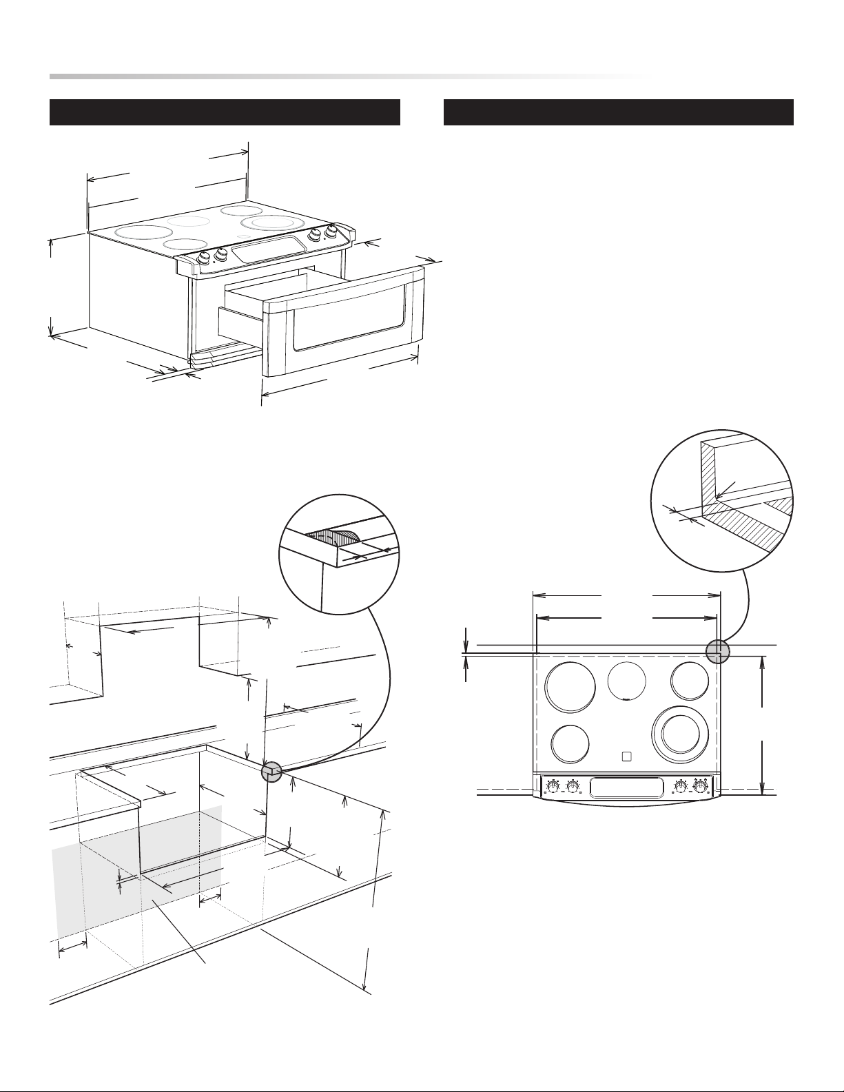
Figure 1
Figure 1 contains many appliance measurements for reference when
planning your kitchen and/or appliance location.
CLEARANCES AND DIMENSIONS APPLIANCE MEASUREMENTS
• Provide adequate clearances between the appliance and adjacent
combustible surfaces.
• Dimensions that are shown in Figures 2 and 3 must be used.
Given dimensions provide minimum clearance. There needs
to be a 30-inch minimum clearance between the top of the
cooking surface and the bottom of upper unprotected wood or
metal cabinets or a 24-inch minimum when bottom of upper
wood or metal cabinets are protected by not less than a 1/4-inch
fl ame retardant millboard covered with not less than no. 29 msg
sheet-steel, 0.015-inch stainless steel, 0.024-inch aluminum or
0.020-inch copper. The gray shaded area in the lower part of
Figure 2 indicates the location for the electrical junction box.
• Contact surface must be solid and level. Pay special attention
to the countertop. Be sure it is solid enough for the weight of
the appliance.
• Check location where the appliance will be installed for proper
electrical supply.
If using countertop with integrated
drip edge, remove 3/4” to clear
31 1/2” width control panel as
illustrated.
Figure 2
Figure 3
To eliminate the risk of burns or fi re by reaching over the
cooktop, cabinet storage space located above the cooktop should
be avoided. If cabinet storage is to be provided, the risk can be
reduced by installing a range hood that projects horizontally a
minimum of 5” beyond the bottom of the cabinets.
2
Page 3
INSTALLATION MANUAL
IMPORTANT NOTES TO THE INSTALLER
• Read all of the Installation Manual before installing the
appliance.
• Remove all packing material from the drawer and cooktop
before connecting the electrical supply to the appliance.
• Observe all governing codes and ordinances.
• Be sure to leave these instructions with the consumer.
IMPORTANT NOTES TO THE CONSUMER
Keep this manual with your Operation Manual for future reference.
• As when using any appliance generating heat, there are certain
safety precautions you should follow. These are listed in the
Operation Manual. Read all and follow carefully.
• Be sure your appliance is installed and grounded properly by
a qualifi ed installer or service technician. See page 7.
• To eliminate the need to reach over the cooktop, cabinet storage
space above the cooktop should be avoided or a range hood
installed.
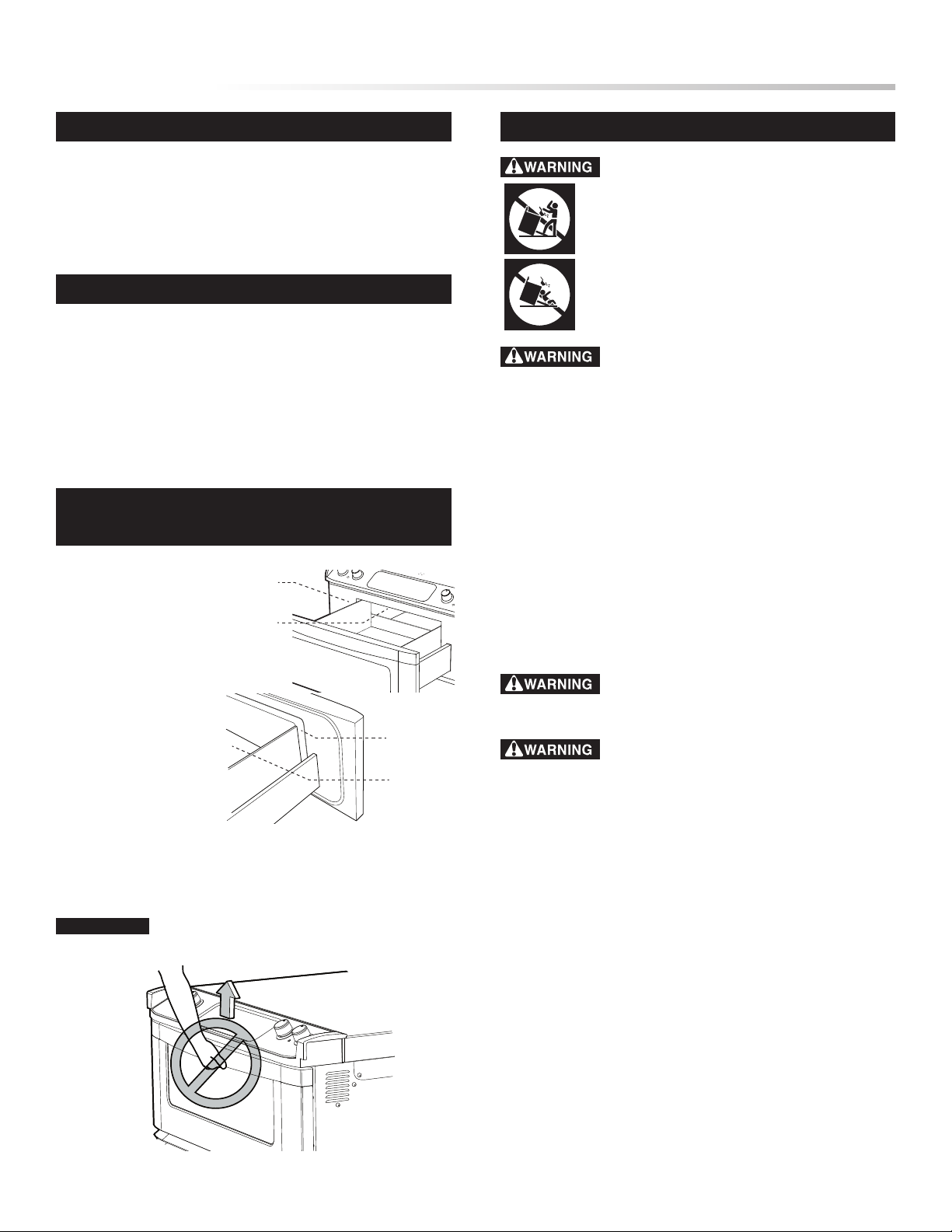
UNPACKING AND EXAMINING YOUR
APPLIANCE
1 Remove all packing
materials from inside
the Microwave Drawer.
DO NOT RE MOV E
THE WAVE GU IDE
COV E R , w h ich is
located on the top of
the Microwave Drawer
cavity.
2 Remove the fe at ure
sticker, if there is one.
Check the drawer for
any damage, such as
mis ali gne d o r b ent
d r aw e r , d a mage d
drawer seals and sealing surfaces, broken or loose drawer guides
and dents inside the drawer or on the front side of the drawer. If
there is any damage, do not operate the Microwave Drawer and
contact your dealer or a SHARP AUTHORIZED SERVICER.
IMPORTANT
wave Drawer handle.
Do not lift or move this appliance by the Micro-
Sealing
Surface
Waveguide
Cover
Sealing
Surface
Microwave
Drawer
Cavity
IMPORTANT SAFETY INSTRUCTIONS
If the information in this manual is not followed
exactly, a fi re or electrical shock may result causing
property damage, personal injury or death.
• ALL APPLIANCES CAN TIP
• INJURY TO PERSONS COULD RESULT
• INSTALL ANTI-TIP BRACKET PACKED
WITH APPLIANCE
To reduce the risk of tipping the appliance, it
must be secured by the Anti-Tip bracket attached to the appliance.
See page 4 and page 6.
• This appliance must be electronically grounded in accordance
with local codes, or in their absence, with the National Electrical
Code ANSI/NFPA No. 70—latest edition in United States.
• The installation of appliances designed for manufactured
(mobile) home installation must conform with Manufactured
Home Construction and Safety Standard, title 24CFR, part
3280 [Formerly the Federal Standard for Mobile Home
Construction and Safety, title 24, HUD (part 280)] or when such
standard is not applicable, the Standard for Manufactured Home
Installation 1982 (Manufactured Home Sites, Communities and
Setups), ANSI Z225. 1/NFPA 501A- latest edition, or with local
codes in United States.
• Make sure the wall coverings and the cabinets around the
appliance can withstand the heat generated by the appliance.
Never leave children alone or unattended in the
area where an appliance is in use. As children grow, teach them
the proper, safe use of all appliances.
Stepping, leaning or sitting on the drawer of this
appliance can result in serious injuries and can also cause damage
to the appliance.
• Do not store items of interest to children in the cabinets
above the appliance. Children could be seriously burned
climbing on the appliance to reach items.
• To eliminate the need to reach over the cooktop, cabinet storage
space above the cooktop should be avoided.
• Do not use the drawer as a storage space. This creates a
potentially hazardous situation.
• Never use the applia nce for warming or heating the
room.
• Do not store or use gasoline or other fl ammable vapors and
liquids near this or any other appliance. Explosions or fi res
could result.
• Reset al l controls to the “off ” position after using a
programmable timing operation.
3
Page 4

INSTALLATION MANUAL
180˚
240V
208V
Screw
Screw
Measure
thickness
Back of unit
Anti-Tip bracket
Loosen screws to adjust
Countertop
thickness +1/16"
from bottom of
cooktop glass bracket
to top of Anti-Tip bracket
INSTALLATION
• Review and plan ahead all safety instructions, cabinet
clearances and dimensions, power supply placement and
electrical requirements before installing.
• Proper installation is the responsibility of the installer and
product failure due to improper installation is not covered by
warranty.
Note: This appliance must be properly grounded
Attention Installer: This appliance must be hard wired (direct
wired) into an approved junction box. A plug and receptacle is
NOT permitted on this product.
A SELECTING 208 OR 240 VOLT CONNECTION
This appliance can be set for 208V or 240V. The voltage setting for
your appliance is pre-set at 240V from the factory. Follow these
steps to change the voltage setting.
1 Locate the voltage switch on the left side of the appliance
(facing the front). See Figure 4.
2 Remove the screw and rotate the switch plate 180˚ as indicated
in the Figure 5.
3 Reinsert the switch plate and replace screw as indicated
in Figure 6. The voltage setting is indicated by the visible
marking.
B ADJUSTING ANTI-TIP BRACKET
Measure the thickness of the counter. See Figure 7. Locate the
Anti-Tip Bracket on the backside of the appliance. See Figure 8.
Loosen screws and adjust space between the glass cooktop and
bracket to match the counter thickness plus 1/16”. See Figure 9.
Tighten the screws to secure the bracket at the correct counter height
dimension.
Figure 7
Figure 4
Figure 5
Figure 6
Figure 8
Figure 9
4
Page 5

INSTALLATION MANUAL
13 7/8"
from top of
counter
2 1/4"
from
front edge of
countertop
stop screw locations
Stop screw
installed
in step "C"
C INSTALL THE STOP SCREWS
IMPORTANT
indicated on page 2 before installing the appliance. These two
stop screws prevent the appliance from sliding out of position during
operation. Attach the stop screws (supplied in the screw bag) to the
right and left sides of the cabinet opening as specified. See Figure
10. Use a 1/16” drill bit to pre-drill holes.
Confirm all cut-out openings and clearances as
F PUSH THE UNIT BACK UNTIL IT HITS THE STOP
SCREWS INSTALLED IN STEP “C”
Figure 12
See Figure 12.
G LIFT THE FRONT OF THE UNIT UP SLIGHTLY (ABOUT
1/2”) AN D PUSH BACK UNTIL THE SLOTS ON THE
MOUNTING BRACKET ENGAGE THE STOP SCREWS.
See Figure 13.
Figure 10
D
IMPORTANT
Do not lift or move this appliance by the
Microwave Drawer handle.
POSITION THE APPLIANCE IN FRONT OF THE OPENING
AND PLACE THE ELECTRICAL CONDUIT CLOSE TO THE
LOCATION OF THE JUNCTION BOX.
If needed, drill a 1” hole in the cabinet side or bottom to allow
the conduit access to the junction box. DO NOT CONNECT until
installation of the appliance is complete in the cabinet.
E PLACE THE APPLIANCE INTO OPENING
It is suggested that two people lift the appliance into place, carefully
setting the side metal flanges under the cooktop glass on the edges of
the countertop opening. Check that the appliance clears the cabinet
face frame. Tilt the appliance as you slide it back so that it will clear.
The unit will have to be pushed in until the front feet are behind the
cabinet face frame. See Figure 11.
Figure 13
H LOWER THE APPLIANCE UNTIL IT RESTS ON THE
COUNTERTOP.
Confirm that the slots on the mounting bracket have engaged the
stop screws. See Figure 14.
Figure 14
If the cooktop does not fit properly on the counter top, the mounting bracket may not be positioned properly on the stop screws. To
correct, slide the appliance out one inch and follow instructions
from
F above.
Figure 11
5
Page 6

INSTALLATION MANUAL
I MAKE SURE THE EDGE OF THE COUNTERTOP FITS
FLUSH AGAINST THE END OF THE FRONT CONTROL
PANEL. See Figure 15.
Figure 15
CHECKING INSTALLATION
To check if the device is installed and engaged properly, open the
Microwave Drawer fully and gently apply medium force in the
center of the handle until movement of the appliance is detected.
Continue pressing until the Anti-Tip bracket is engaged and movement stops. A small amount of movement is acceptable at the back
of the appliance top, but it should be stable and not tip once the
Anti-tip bracket is engaged. Stop pressing on the Microwave Drawer
handle and close.
To check that the unit will not slide out, open the Microwave Drawer
fully and then apply gentle outward pressure. The unit should not
slide toward you. If the unit does slide, check installation beginning
with
C on page 5.
National Electrical Codes, ANSI/NFPA No. 70-Latest Edition.
Effective January 1, 1996, the national Electrical Code requires that
new, but not existing, construction utilize a four-conductor connec
tion for this appliance class. When installing this appliance in new
construction, a mobile home, recreational vehicle or an area where
local codes prohibit grounding through the neutral conductor, follow
the instructions in the section on NEW CONSTRUCTION AND
FOUR-CONDUCTOR BRANCH CIRCUIT CONNECTOR.
ELECTRICAL SHOCK HAZARD
• Electrical ground is required on this appliance.
• Do not connect to the electrical supply until appliance is
permanently grounded.
• DISCONNECT POWER TO THE CIRCUIT BREAKER
OR FUSE BOX BEFORE MAKING THE ELECTRICAL
CONNECTION
• This appliance must be connected to a grounded, metallic,
permanent wiring system or the grounding connector of the
power cord should be connected to the grounding terminal or
wire lead on the appliance.
• Do not use a gas supply line for grounding this appliance.
• Failure to heed these warnings could result in a fire, personal
injury or electrical shock.
.
-
ELECTRICAL CONNECTIONS
ELECTRICAL REQUIREMENTS
This appliance must be supplied with the proper voltage and fre
quency, and connected to an individual, properly grounded branch
circuit, protected by a circuit breaker or fuse having amperage as
noted on the rating plate. (Rating Plate is located on the faceplate
behind the Microwave Drawer front.) See Figure 16.
Breaker or fuse size:
240V 40 Amps
208V 40 Amps
NOTE: Check Local Codes for required breaker size.
All electrical wiring and hookup for this appliance should be by a
qualified electrician.
Be familiar where the main appliance disconnect is located.
Check with local utilities for electrical codes which apply in your
area. Failure to wire your appliance according to governing codes
could result in hazardous conditions. If there are no local codes, your
appliance must be wired and fused to meet the requirements of the
-
Rating plate
Figure 16
6
Page 7

INSTALLATION MANUAL
Red wires
Green wires
White wires (nutral)
Black wires
Conduit connector
(not supplied)
Appliance
conduit & wires
Power supply
Red wires
White wires (nutral)
Black wires
Green wire
(ground)
Conduit connector
(not supplied)
Appliance
conduit & wires
Power supply
POWER CONNECTIONS
This appliance is manufactured with a neutral (white) power supply
wire and a cabinet-connected green grounding wire.
Connect the appliance cable to the junction box through the ULlisted conduit connector. Complete electrical connection according
to local codes and ordinances. For preferred junction box location,
see Figure 2, page 2.
NOTE TO ELECTRICIAN: The armored cable leads supplied
with this appliance are UL recognized for connection to larger
gauge household wiring. The installation of the leads is rated
at temperatures much higher than the temperature rating of
household wiring. The current carrying capacity of the conductor
is governed by the temperature rating of the installation around
the wire, rather than the wire gauge alone.
Improper connection of aluminum house wiring
to copper leads can result in an electrical hazard or fire. Use only
connectors designed for joining copper to aluminum and follow
manufacturer’s recommended procedure closely.
GENERAL NOTE FOR WIRE NUT APPLICATIONS:
The proper size wire nut shall be placed over the stripped
leads and the wire nut twisted until the wire nut can not be
pulled from the leads. No conductor shall be exposed in the
connection.
3-WIRE CONNECTION
When local codes permit connecting the cabinet-grounding conductor to the neutral (white) wire.
1 Disconnect the power supply.
2 In the junction box connect the appliance and residence cable
wires as shown in Figure 18.
Figure 18
4-WIRE CONNECTION
When installing to a 4-wire electrical system, new construction,
mobile home and recreational vehicle or when local codes do not
permit grounding through neutral.
1 Disconnect the power supply.
2 In the junction box connect the appliance and residence cable
Figure 17
wires as shown in Figure 17.
REINSTALL JUNCTION BOX COVER
Do not shorten the flexible conduit. The conduit strain relief clamp
(supplied by installer) must be securely attached to the junction box
and the flexible conduit must be securely attached to the clamp. If
the flexible conduit will not fit with the junction box, do not install
the appliance until a clamp of proper size has been obtained.
7
Page 8

INSTALLATION MANUAL
MODEL AND SERIAL NUMBER LOCATION
The Rating Plate, including model and serial number, is located on
the faceplate behind the Microwave Drawer front.
CARE, CLEANING AND MAINTENANCE
Refer to the Operation Manual for cleaning instructions. If removing
the appliance is necessary for cleaning or maintenance, disconnect
the electrical power supply. Reinstall in reverse order making sure
to level the appliance and check electrical connections. See pages 4
and 5 for proper installation instructions.
BEFORE YOU CALL FOR SERVICE
Read the BEFORE YOU CALL and operating instruction sections
in your Operation Manual. It may save you time and expense. The
list includes common occurrences that are not the result of defective
workmanship or materials in this appliance.
Refer to the warranty in your Operation Manual for our toll-free
service number and address. Please call or write if you have inquiries
about your appliance product and/or need to order parts.
TIN S EB 4 33M R R0
SHARP ELECTRONICS CORPORATION
Sh arp Plaza, Mahwah , New Jersey 07430- 21 35
8
PRIN TED IN USA
 Loading...