

Page 1
GP2A16/GP2A18F
GP2A16/GP2A18F
Visible Light Cut-off Type
Photointerrupters with
Connector
■ Features
1. Visible light cut-off type
2. Dust-protection type (GP2A18F
)
3. Long focal distance type
Detecting range: GP2A16: 2.0 to 7.0 mm,
GP2A18F: 4.0 to 5.0 mm
4. With a 3-pin connector for easier interface
with control circuit
■ Applications
1. Printers
2. Copies
3. Facsimiles
■ Absolute Maximum Ratings
Parameter Symbol Rating Unit
Supply voltage V
∗1
Output voltage
∗
2
Low level output current
∗3
Operating temperature
∗3
Storage temperature
∗1 At non detection (GP2A16
At detection (GP2A18F
∗2 At detection (GP2A16
At non detection (GP2A18F
∗3 The connector should be plugged in/out at normal temperature.
)
)
)
)
CC
V
O
I
OL
T
opr
T
stg
(
Ta= 25˚C
7V
30 V
6mA
- 10 to + 70
- 40 to + 80
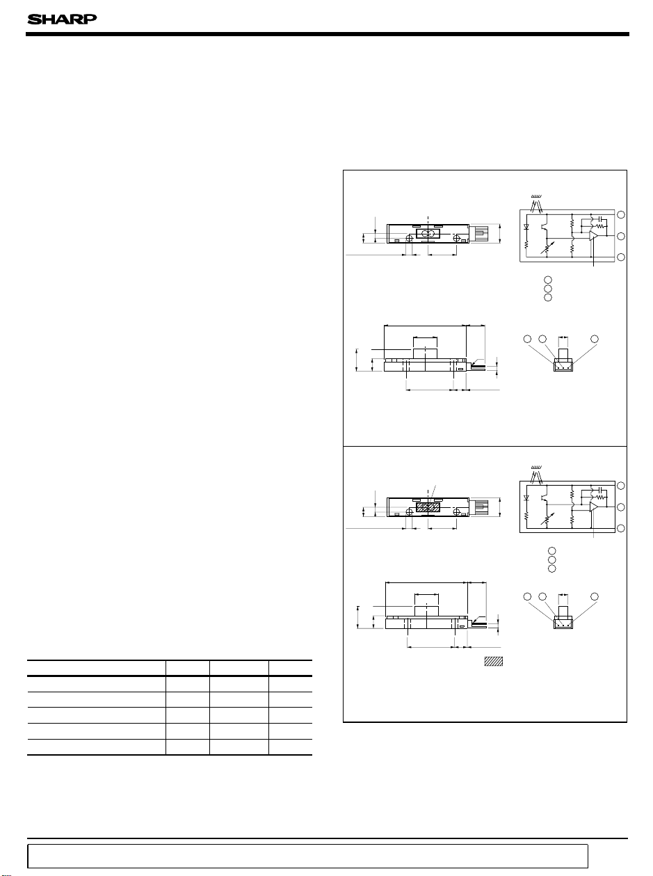
■ Outline Dimensions
GP2A16
0.2
±
0.4-0.2
+
2.0
5.0
± 0.1
2 -φ3.2
0.4-0.2
0.5
+
±
7.5
13.0
GP2A18F
0.2
±
0.4-0.2
+
2.0
5.0
±
±
0.5
13.0
0.4-0.2
+
0.1
7.5
2 -φ3.2
)
43.0
12.5
24.0
43.0
12.5
24.0
15.0
±
±
15.0
±
±
±0.5
0.3
(
)
10.4
0.2
❈
±
±
0.2
Polyester film
±
0.3
0.2
±
0.2
0.2
7.5
*( ): Reference dimensions
❈ JAPAN AMP made EI3 - pin
connector No. 171825- 3
0.5
(
)
10.4
❈
±
0.2
7.5
**
*( ): Reference dimensions
❈ JAPAN AMP made EI3 - pin
connector No.171825- 3
(
Unit:mm
Internal connection diagram
0.4-0.2
+
10.0
Comparator
1 Vcc
2
Vo
3 GND
±
0.2
5.0
2
3
)
2.7
(
Internal connection diagram
0.4-0.2
+
10.0
Comparator
1 Vcc
2 Vo
3 GND
±
0.2
5.0
2
3
)
2.7
(
Polyester film
)
1
2
3
1
1
2
3
1
˚C
˚C
“ In the absence of confirmation by device specification sheets, SHARP takes no responsibility for any defects that occur in equipment using any of SHARP's devices, shown in catalogs,
data books, etc. Contact SHARP in order to obtain the latest version of the device specification sheets before using any SHARP's device.”
Page 2
GP2A16/GP2A18F
■ Electro-optical Characteristics
Parameter
Operating supply voltage V
Dissipation current I
Low level output voltage V
High level output voltage V
∗6
Response time
∗4 At detection
d= 2.0 to 7.0mm using black artwork tape as the reflective object with no external disturbing light as shown in Fig.1
d= 4.0 to 5.0mm using white PPC paper as the reflective object with no external disturbing light as shown in Fig.1
∗5 At non detection
d= 11.0mm or more using black suede as the reflective object with no external disturbing light as shown in Fig.1
d= 4.0 to 5.0mm using black artwork tape as the reflective object with no external disturbing light as shown in Fig.1
∗6 Definition of response time: As shown in Fig.2
GP2A16
GP2A18F
GP2A16
GP2A18F
GP2A16
GP2A18F
Rise time t
Fall time t
Symbol Condition MIN. TYP. MAX. Unit
CC
CC
OL
OH
r
f
(
Unless otherwise specified, V
Ta=- 10 to + 70˚C
VCC= 5V, R
= 5V, R
V
CC
V
= 5V, IOL=3mA, ∗4
CC
V
= 5V, I
CC
VCC= 5V, R
= 5V, RL=10kΩ , ∗4
V
CC
=,∗5
L
L
=3mA, ∗5
OL
=10kΩ , ∗5
L
RL=10kΩ
4.5 5.0 5.5 V
-2750mA
-2750mA=,∗4
- 0.2 0.4 V
-
4.7 - - V
4.7
- - 2.0 ms
- - 2.0 ms
(
GP2A16
(
GP2A18F
(
GP2A16
(
GP2A18F
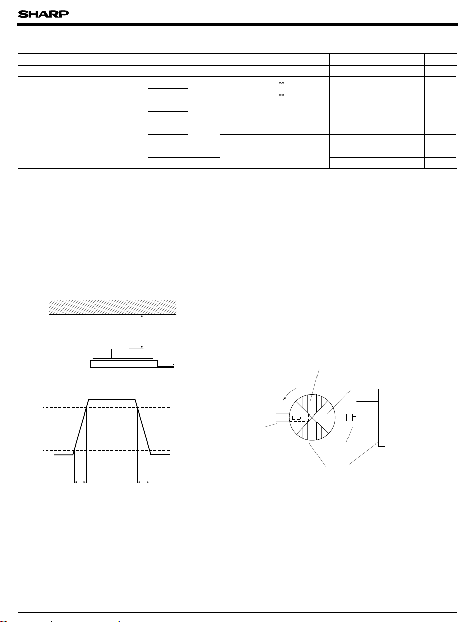
Fig. 1 Vo Test Arrangement
Reflective object
d
Test Arrangement
Non detecting portion
Fig. 2 Vout waveform
Rotation
90%
Detecting portion
= 5V, Ta= 25˚C
CC
0.2
-
)
)
)
)
d
0.4
)
V
-
V
GP2A16/GP2A18F
100%
tr
tf
1. Rotation disk shall be φ 40mm or more. And it is in accordance with above test arrangement.
2. Rotation frequency shall be 5Hz or less. Output shall not be DC.
GP2A16/GP2A18F
Rotation disk
Page 3

GP2A16/GP2A18F
Fig. 3-a Low Level Output Voltage vs.
Ambient Temperature
0.5
)
V
0.4
(
OL
0.3
0.2
0.1
Low level output voltage V
0
- 25 0 25 50 75 100
Ambient temperature Ta (˚C
I
OL
(
GP2A16
= 3mA
1mA
)
Fig. 4-a Dissipation Current vs.
Supply Voltage
30
)
mA
(
CC
20
T
= 70˚C
a
25˚C
- 10˚C
(
GP2A16
Fig. 3-b Low Level Output Voltage vs.
)
Ambient Temperature
0.5
)
V
0.4
(
OL
0.3
0.2
Low level output voltage V
0.1
0
- 25 0 25 50 75 100
Ambient temperature Ta (˚C
(GP2A18F
I
= 3mA
OL
1mA
)
)
Fig. 4-b Dissipation Current vs.
)(
Supply Voltage
30
)
mA
(
CC
20
T
= 70˚C
a
25˚C
- 10˚C
GP2A18F
)
Dissipation current I
10
4.5 5.0 5.5
Supply voltage V
)
(V
CC
Fig. 5-a Detecting Distance Characteristics
=5V
CC
= 25˚C
a
)
)
5
4
3
)
V
(
E
V
2
1
0
024681012
Detecting distance d (mm
V
T
Reflective object:
Black artwork tape
Reflective object:
Black suede
(GP2A16
Dissipation current I
10
4.5 5.0 5.5
Supply voltage VCC (V
)
Fig. 5-b Detecting Distance Characteristics
=5V
CC
= 25˚C
a
)
)
5
4
3
)
V
(
E
V
2
1
0
024681012
Detecting distance d (mm
V
T
Reflective object:
White PPC paper
Reflective object:
Black artwork tape
(GP2A18F
Page 4

Test Circuit for Detecting Position Characteristics
(
Reflective
object
d
GP2A16/GP2A18F
Test Arrangement
V
E
V
GP2A16/GP2A18F
V
CC
+
-
Test Circuit
= 5V
■ Recommended Connectors on the Inserted Side
● JAPAN AMP made El series connectors
(Standard type
Housing color Black Blue Green Red
Housing Model No.
Special
terminal
Model. No.
)
Natural
color
2-171822-3 4-171822-3 6-171822-3 8-171822-3
171822-3
AWG
size
26 to 20
30 to 26
AWG
AWG
Product
shape
Bulk
Chain
Bulk
Chain
Material
Brass 170204-1
phosphor
bronze
Brass 170262-1
phosphor
bronze
Brass 170205-1
phosphor
bronze
Brass 170263-1
phosphor
bronze
Model No.
170204-2
170262-2
170205-2
170263-2
● JAPAN AMP made El series connectors
(Low profile type
● JAPAN AMP made El series connectors
(Amp mass termination
❈ Terminal Material: phosphor bronze
GP2A16/GP2A18F
)
)
Housing color Black Blue Green Red
Housing Model No. 172142-3
Special
terminal
Model. No.
(
Material:
phosphor
)
bronze
Housing-terminal
united type
connector
Natural
color
2-172142-3 4-172142-3 6-172142-3 8-172142-3
AWG
AWG
26 to 22
AWG
30 to 26
Product shape Model No.
size
Bulk 170369-1
Chain 170354-1
Bulk 170370-1
Chain 170355-1
)
AWG28
(
Green
AWG26
(
Natural
)
color
172054-3 172053-3 172052-3 172051-3
AWG24
(
Black
)
)
AWG22
(
Red
)
●
Please refer to the chapter “Precautions for Use”(Page 78 to 93
)
 Loading...