

Page 1
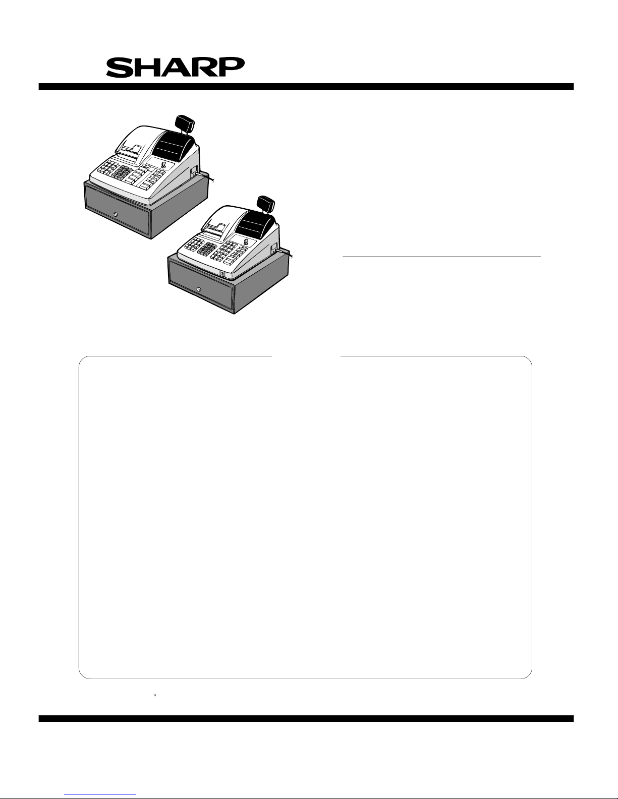
INSTALLATION MANUAL
CODE: 00ZERA310VIME
ELECTRONIC
CASH REGISTER
MODEL ER-A310
MODEL ER-A330
SRV Key : LKGIM7113RCZZ
PRINTER: ER-A310 : CR-510
: ER-A330 : UCR-812A
(For "V" version)
CHAPTER 1. GENERAL. . . . . . . . . . . . . . . . . . . . . . . . . . . . . . . . . . . . . . . . . . . . . . 1
CHAPTER 2. LIST OF OPTIONS. . . . . . . . . . . . . . . . . . . . . . . . . . . . . . . . . . . . . . . 1
CHAPTER 3. REMOVING THE TOP CAB INE T (For ER -A310 & ER-A330). . . . . . 2
CHAPTER 4. REMOVING THE BOTTOM CABI NET (Only for ER-A 330). . . . . . . . 3
CHAPTER 5. REMOVING THE PRINTE R UNIT (For ER -A310 & ER-A330) . . . . . 4
CHAPTER 6. REMOVING THE MAIN PWB (For ER-A3 10 & ER-A330). . . . . . . . . 4
CHAPTER 7. REMOTE DRAWER: ER-0 4DW (For ER-A3 10 & ER-A330). . . . . . . 5
CHAPTER 8. DRAWER FIXING KIT (DKIT –8633RCZZ ). . . . . . . . . . . . . . . . . . . . . 6
CHAPTER 9. SHIELD PLATE KIT: DKIT-8 66 6BHZZ (Only for ER-A3 30 ). . . . . . . . 7
CHAPTER 10. ONE HOLE CA SHI ER KEY KI T. . . . . . . . . . . . . . . . . . . . . . . . . . . . . 8
CHAPTER 11. KE Y TOP KIT : ER-11 KT7/12KT7 /2 2KT7/11DK7/ 51DK7
(For ER-A310 & ER-A330). . . . . . . . . . . . . . . . . . . . . . . . . . . . . . . . . 8
CONTENTS
SHARP CORPORATI ON
This document has been published to be used
for after sales service only.
The contents are subject to change without notice.
Parts marked with "!" is important for maintaining the safety of the set. Be sure to replace these parts with specified ones for
maintaining the safety and performance of the set.
ER-A310
ER-A330
Page 2
CHAPTER 1. GENERAL
This manual describes the ER-A310/A330 disassembly procedures
and the opti on attachm ent pro cedures. For a ssembl y procedure s, reverse the disassembly procedures. For attachmen t of options which
do not require special descriptions, descriptions are omitted.
Note for operations
• Before operatio n, ground the operator’s body and perform other
necessary measure against static electricity.
• During operations, disconnect the AC cord from the outlet.
• After completion of operations, connect the connectors.
• After completion of operations, be sure to perform the master reset.
Master reset (All memory clear)
There are two possible methods to perform a master reset.
• MRS-1
Used to clear all memory contents and return machine back to its
initial settings. retu rn keyboard back to default. for default keyboard
layout.
Procedure-1 (with SRV key)
1) Unplug the AC cord from the wall outlet.
2) Set the MODE switch to the (SRV′) position.
3) Plug in the AC cord to the wall outlet.
4) While holding down JOURNAL FEED key, turn to (SRV) position
from (SRV′) position.
Procedure-2 (without SRV key)
1) Turn the mode switch to the (REG) position.
2) Ensure the batteries are not installed in the ba ttery compartment
and insert the plug into the ou tlet.
3) The right most decimal point will blink for a few seconds.
4) The register will sound three beeps.
5) The register will display " ."
CHAPTER 2. LIST OF OPTIONS
1. Sales options
No. NAME MODEL DESCRIPTIONS
1 REMOTE DRAWER ER-04DW 5B/8C
2 COIN CASE ER-58CC 5B/8C
3 COIN CASE COVER ER-03CV
4 KEY TOP KIT ER-11KT7 1 × 1 key top
ER-12KT7 1 × 2 key t op
ER-22KT7 2 × 2 key t op
ER-11DK7 1 × 1 dummy key
ER-51DK7 5 × 1 dummy key
2. Service options
No. NAME PARTS CODE PRICE RANK DESCRIPTIONS
1 SRV KEY
LKGIM7113RCZZ
AK
2 MODE KEYGRIP COVER
LKGIM7126RCZZ
AL OP key only
3 DRIP-PROOF KEYBOARD COVER
GCÇVH7126BHZZ
BE
4 SHIELD PLATE KIT
DKIT-8666BHZZ
BL Only for ER-A330
5 ONE HOLE CASHIER KEY KIT
6 DRAWER FIXING KIT
3. Supplies
No. NAME PARTS CODE PRICE RANK DESCRIPTIONS
1 ROLL PAPER
DPAPR1006CSZZ
AR
2 INK ROLLER (ER-A310)
NRÇLR6652RCZZ
AZ
3 INK ROLLER (ER-A330)
NRÇLR6638RCZZ
AY
4 INK FOR STAMP
UINK-1001CCZZ
AK
1
Page 3
CHAPTER 3. REMOVING THE TOP
CABINET (For
ER-A310 & ER-A330)
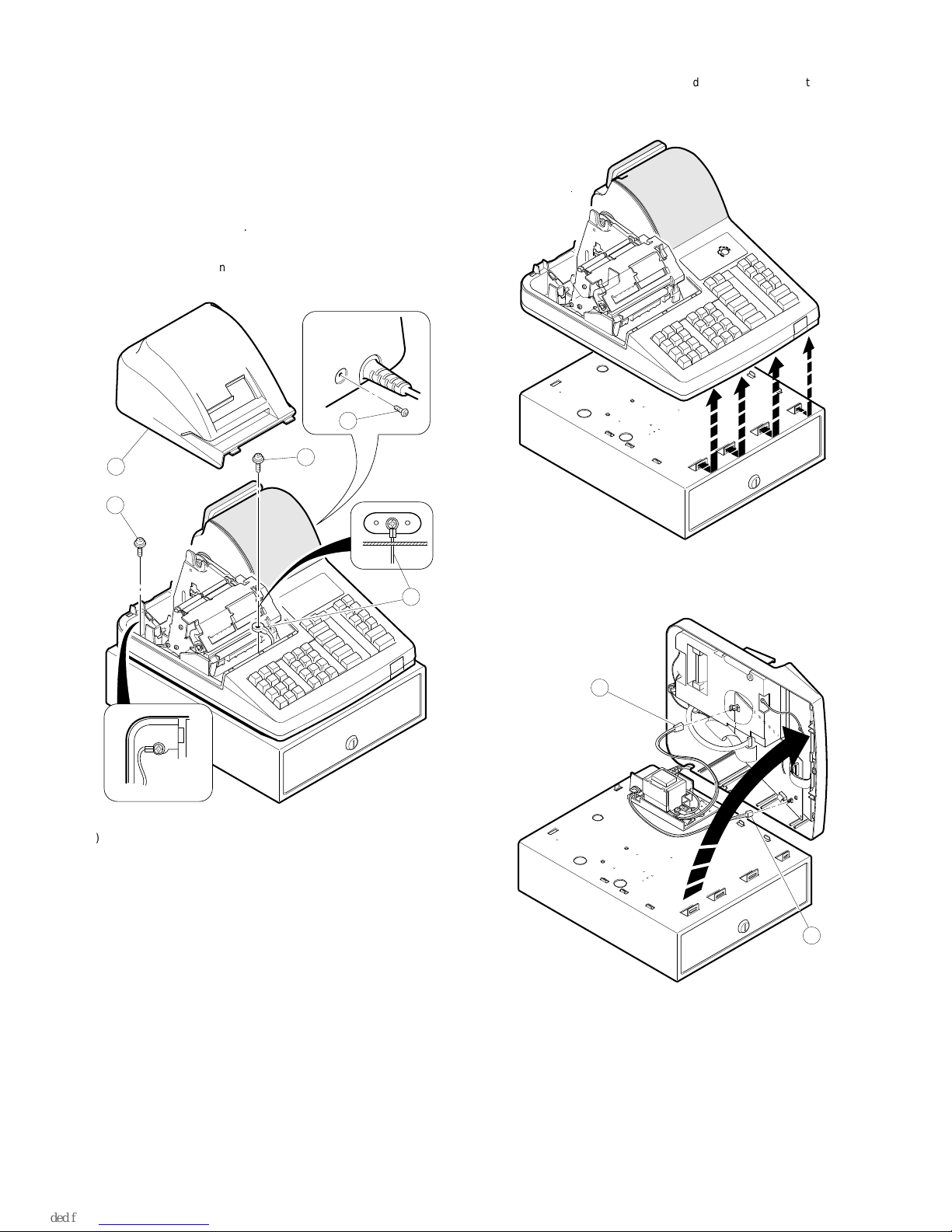
1. ER-A310
1) Remove the printer cover 1.
2) Remove the two screws
2
.
3) Remove the screw
3
and grounding wire 4.
4) Separate the top cabinet and the drawer unit.
Note: Tra nsformer cable 5 and the drawer cable on the drawer
unit are conn ected to the main PWB on the top ca bi net. Be
careful when s eparating them from t h e drawer unit.
5) Remove transformer cable
5
and drawer cable 6 from the main
PWB.
1
2
3
4
2
5
6
2
Page 4
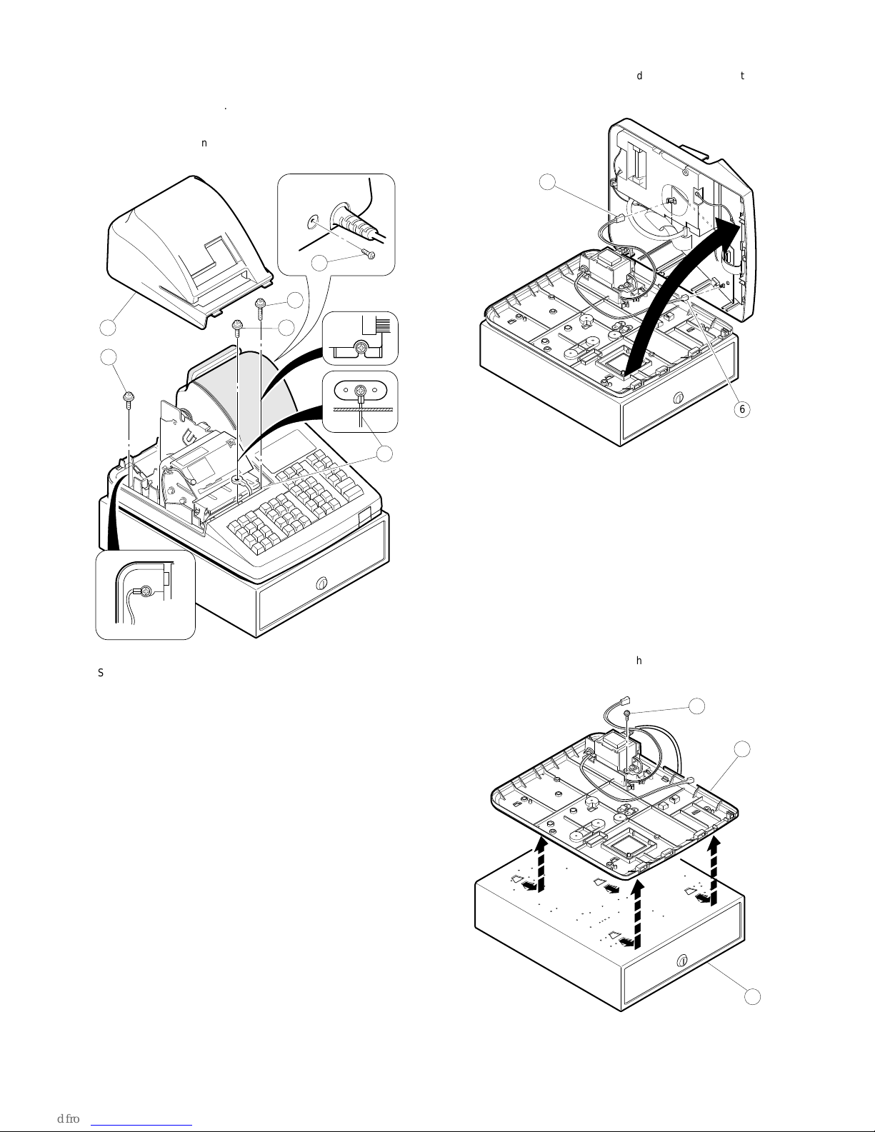
2. ER-A330
1) Remove the printer cover 1.
2) Remove the three screws
2
.
3) Remove the screw
3
and grounding wire 4.
4) Separate the top cabinet and the bottom cabinet.
Note: Tra nsformer cable
5
and the drawe r cable on the bottom
cabinet are connected to the ma in PWB on the top cabinet.
Be careful when separating them from the bottom cabinet.
5) Remove transformer cable
5
and drawer cable 6 from the main
PWB.
CHAPTER 4. REMOVING THE
BOTTOM CABINET
(Only for ER-A330)
1. ER-A330
1) Remove the top cabinet.
2) Remove the bottom cabinet
1
from the drawer unit 2.
13
4
2
2
2
5
6
1
2
A
B
B
A
A
B
3
3
Page 5
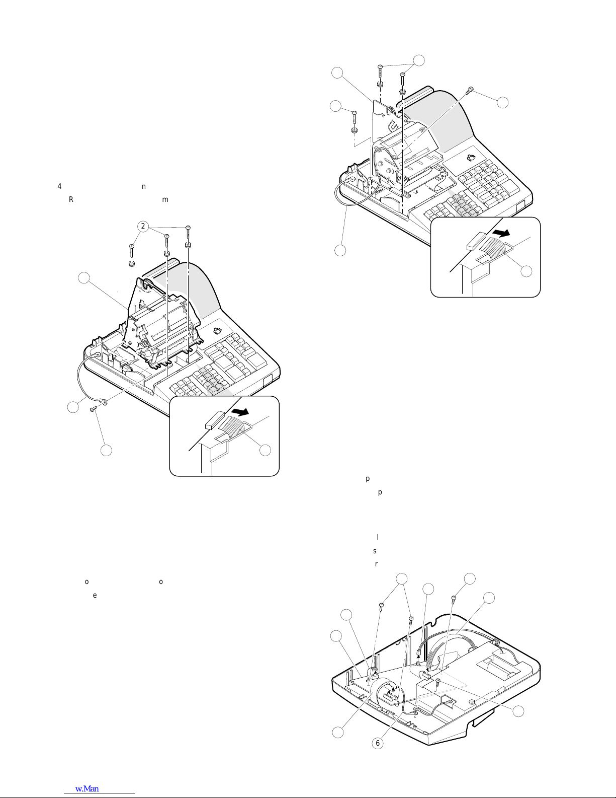
CHAPTER 5. REMOVING THE
PRINTER UNIT (For
ER-A310 & ER-A330)
1. ER-A310
1) Remove the top cabinet.
2) Remove the printer cable
1
from the main PWB.
3) Remove the three screws
2
.
4) Remove the screw
3
and grounding wire 4.
5) Remove the printer unit
5
from the top cabinet.
2. ER-A330
1) Remove the top cabinet.
2) Remove the printer cable
1
from the main PWB.
3) Remove the three screws
2
.
4) Remove the screw
3
and grounding wire 4.
5) Remove the printer unit
5
from the top cabinet.
CHAPTER 6. REMOVING THE MAIN
PWB (For ER-A310 &
ER-A330)
1. ER-A310/A330
1) Remove the top cabinet.
2) Remove the printer unit.
3) Remove the following connector cables from the main PWB.
Dry battery cable
1
Pop up display cable
2
Note: The pop-up cab le is fixed with the ho lder not to m ake con-
tact with the heat radiating plate on the main PWB. Be
careful of it whe n installing.
Mode switch cable
3
Keyboard cable
4
4) Remove the screw 5 and grounding wire 6.
5) Remove the free screws
7
and main PWB 8.
1
2
3
4
5
1
3
4
5
2
2
1
2
3
4
5
6
7
8
7
4
Page 6
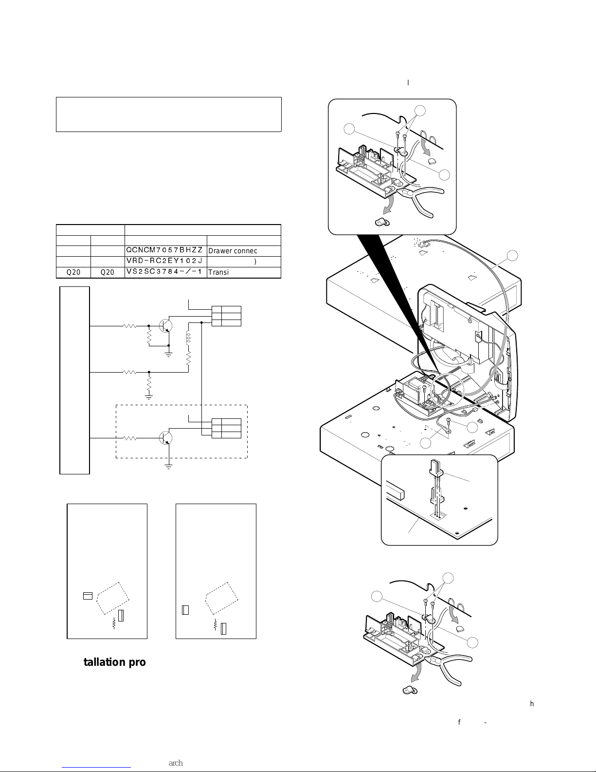
CHAPTER 7. REMOTE DRAWER:
ER-04DW (For
ER-A310 & ER-A330)
CAUTION:
The drawer un it sho ul d be se curely fitte d to th e sup po rtin g platform
to avoid instability when the drawer is open.
1. Outline
The ER-A310/A330 allows connection of one remote drawer ER04DW.
Note on the drawer connector
The main PW B has no part for conn ection of the remote drawer. In
order to connect the re mote drawer, the following pa rts must be attached to the main PWB.
LOCATION No.
ER-A310 ER-A330 PARTS CODE DESCRIPTION
CN16 CN16
QCNCM7057BHZZ
Drawer connector
R80 R89
VRD-RC2EY102J
Resistor (1KΩ)
Q20 Q20
VS2SC3784-/-1
Transistor (2SC3784)
2. Installat ion procedure f or ER-A310
1) Remove the top cabinet.
2) Remove the main PWB.
3) Solder the drawer con nector CN16, the resistor (1 kΩ) R80, and
the transistor (2SC3784) Q20 t o the main PWB.
4) Replace the main PWB.
5) Connect the drawer cable to the drawer conn ector on the main
PWB.
6) Use nippers to cut off drawer cable binding holder
1
on the tran s
cover, and bind drawer cable
2
of the ER-04DW.
Screw
3
used in this case is an accessory of the ER-04DW.
7) Use nippers to cot off the drawer cable split pin of the top cabinet,
and attac h the top cabinet.
8) Fix ground wire
4
of the ER-04DW on the standard d rawer with
screw
5
.
Screw
5
used in this case is an accessory of the ER-04DW.
DR1
JMS
R53
1K
R54
15K
VP:+24V
L2
R55
15K
ER-A310:Q14
ER-A330:Q21
C3784
CN11
VP:+24V
ER-A310:Q20
ER-A330:Q14
C3784
R56
56K
R57
ER-A310:3.3K
ER-A330:4.7K
ER-A310:R80
ER-A330:R89
1K
DR2
OPTION
DRAWER
STANDARD
DRAWER
IC2
CPU
CN16
R80
1K
Q20
C3784
I
C
2
C
P
U
ER-A310
Main PWB
CN16
R89
1K
Q20
C3784
I
C
2
C
P
U
ER-A330
Main PWB
CN16
2
4
5
ER-04DW
CN16
Main PWB.
1
3
2
1
3
2
5
Page 7
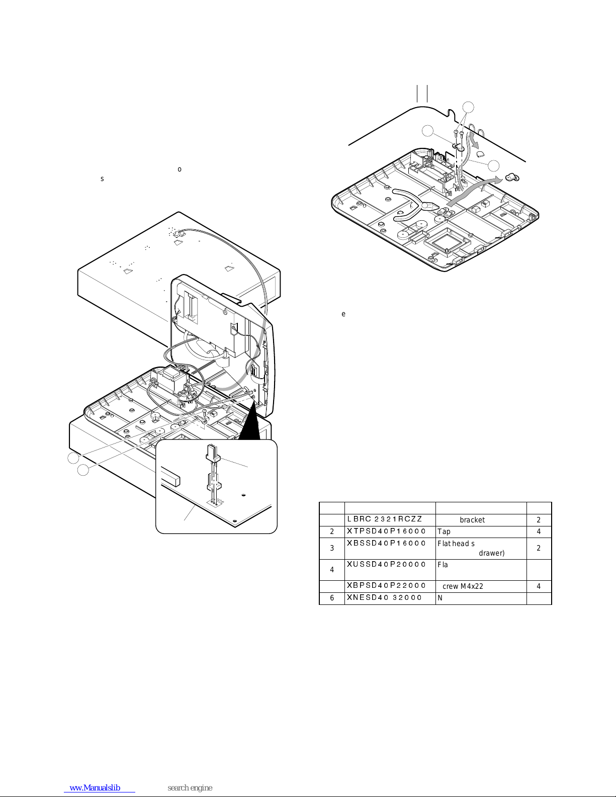
3. Installat ion procedure f or ER-A330
1) Remove the top cabinet.
2) Remove the main PWB.
3) Solder the drawer con nector CN16, the resistor (1 kΩ) R89, and
the transistor (2SC3784) Q20 t o the main PWB.
4) Replace the main PWB.
5) Connect the drawer cable to the drawer conn ector on the main
PWB.
6) Use nippers to cut off drawer cab le b indin g ho lder
1
on the bo ttom
cabinet, and bind drawer cable
2
of the ER-04DW.
Screw
3
used in this case is an accessory of the ER-04DW.
7) Use nippers to cot off the drawer cable split pin of the top cabinet,
and attac h the top cabinet.
8) Fix ground wire
4
of the ER-04DW on the standard d rawer with
screw
5
.
Screw
5
used in this case is an accessory of the ER-04DW.
4. Operat io n te st
CHAPTER 8. DRAWER FIXING KIT
(DKIT–8633RCZZ)
The drawer fixing kit is used for securing the cash drawe r when installing separately from the ECR main unit or remote drawer.
By using two of brackets, the drawer box can be protected from
drifting especially when it is filled with coins.
1. Parts list KIT CODE: DKIT–8633RCZZ
No. Parts code Description Q’ty
1
LBRC2321RCZZ
Fixing bracket 2
2
XTPSD40P16000
Tapping screw M4x16 4
3
XBSSD40P16000
Flat head screw M4x16
(For remote drawer)
2
4
XUSSD40P20000
Flat head screw M4x20
(For standard drawer)
2
5
XBPSD40P22000
Screw M4x22 4
6
XNESD4032000
NUT M4x32 4
4
5
CN16
Main PWB.
1
3
2
6
Page 8
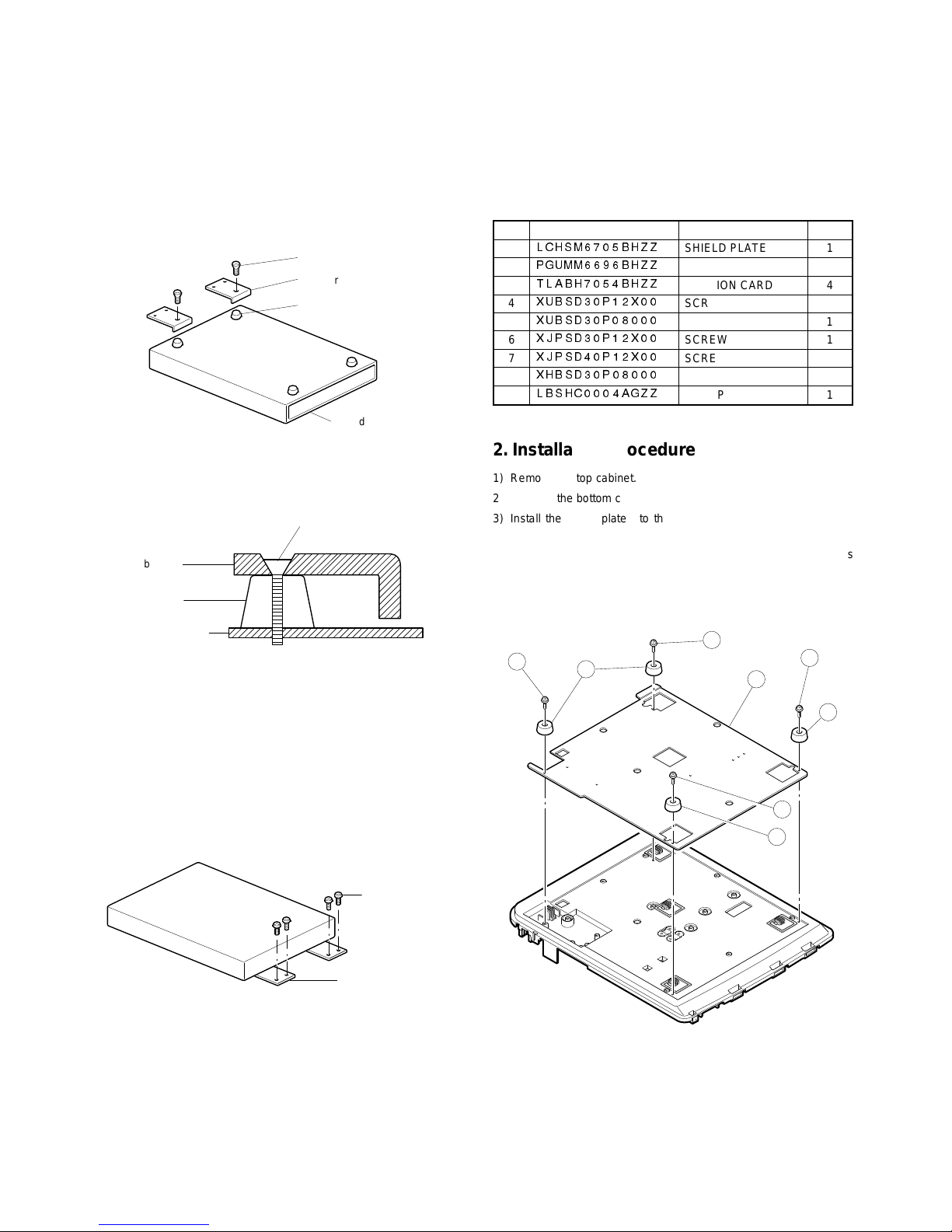
2. Installation proced ure
1) Turn over the drawe r bottom side and remove rub ber footing at
two to locations.
2) Fasten the bracket together with the rubber footing using the p an d
hand screw.
Pay attention for the installing dire ction of the bra cket that the pan
head screw can be inserted properly into the bracket.
Fig. 1
3) Fastening on the table:
Secure the fixing Bracket using the screw (Fig. 2).
If the thickness of the table is less than 15mm, bore a 4.5mm hole
in the table and fasten it with the screw (XBPSD40P22000 - 4pcs.)
and nut (XNESD40- 3 2000 - 4pcs.).
Fig. 2
CHAPTER 9. SHIELD PLATE KIT:
DKIT-8666BHZZ (Only
for ER-A330)
1. Component list
No. PARTS CODE DESCRIPTION Q’TY
1
LCHSM6705BHZZ
SHIELD PLATE 1
2
PGUMM6696BHZZ
GUM LEG 4
3
TLABH7054BHZZ
CAUTION CARD 4
4
XUBSD30P12X00
SCREW 1
5
XUBSD30P08000
SCREW 1
6
XJPSD30P12X00
SCREW 1
7
XJPSD40P12X00
SCREW 1
8
XHBSD30P08000
SCREW 3
9
LBSHC0004AGZZ
CLAMP 1
2. Installation proced ure
1) Remove the top cabinet.
2) Remove the bottom cabinet.
3) Install the shie ld plate
1
to the bottom cabinet and fix it with ???
screws
2
.
4) Attach four gum legs
3
to the shield pla te and fix th em with screws
4
.
5) Replace the top cabinet.
Pan head screw
Fixing bracket
Rubber footing
Cash drawer
Drawer bottom plate
Rubber footing
Fixing br ac ke t
Pan head s c re w
Fixing br ac ke t
Tapping screw
1
2
3
4
3
3
2
2
7
Page 9
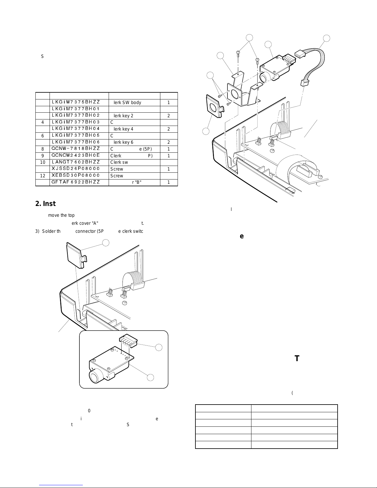
CHAPTER 10. ONE HOLE CLERK
KEY KIT
*
Standard provision for the TQ, TR, and TS versions of the ERA330.
1. Component list
No. PARTS CODE DESCRIPTION Q’ty
1
LKGIW7375BHZZ
Clerk SW body 1
2
LKGIM7377BH01
Clerk key 1 2
3
LKGIM7377BH02
Clerk key 2 2
4
LKGIM7377BH03
Clerk key 3 2
5
LKGIM7377BH04
Clerk key 4 2
6
LKGIM7377BH05
Clerk key 5 2
7
LKGIM7377BH06
Clerk key 6 2
8
QCNW-7818BHZZ
Clerk key cable (5P) 1
9
QCNCW2423BH0E
Clerk connector (5P) 1
10
LANGT7602BHZZ
Clerk switch angle 1
11
XJSSD26P08000
Screw 1
12
XEBSD30P08000
Screw 2
13
GFTAF6922BHZZ
Clerk cover "B" 1
2. Installation proced ure
1) Remove the top cabinet.
2) Remove the clerk cover "A"
1
from the top cabinet.
3) Solder the clerk connector (5P)
2
to the clerk switch body 3.
4) Connect the clerk key cable (5P)
4
to the clerk switch body 3.
5) Attach the clerk angle
5
to the clerk switch body 3 and fix with
screw
6
(XJSSD26P08000).
6) Install the clerk switch body
3
to the clerk cover "B" 7 then install it
the top cabinet and fix with s crews
8
(XEBSD30P08000).
7) Connect the clerk key cable (5P)
4
to location No. NC9 on the main
PWB.
3. Operat io n te st
CHAPTER 11. KEY TOP KIT
1. Outline
The ER-A460 employs the following key top (option) to allo w additional installation of the key top and change in the key layout.
MODEL NAME DESCRIPTION
ER-11KT7 1 × 1 Key top
ER-12KT7 1 × 2 Key top
ER-22KT7 2 × 2 Key top
ER-11DK7 1 × 1 Dummy key
ER-51DK7 5 × 1 Dummy key
1
Top cabinet
2
3
4
5
6
7
8
3
CN9
Main PWB.
8
Page 10
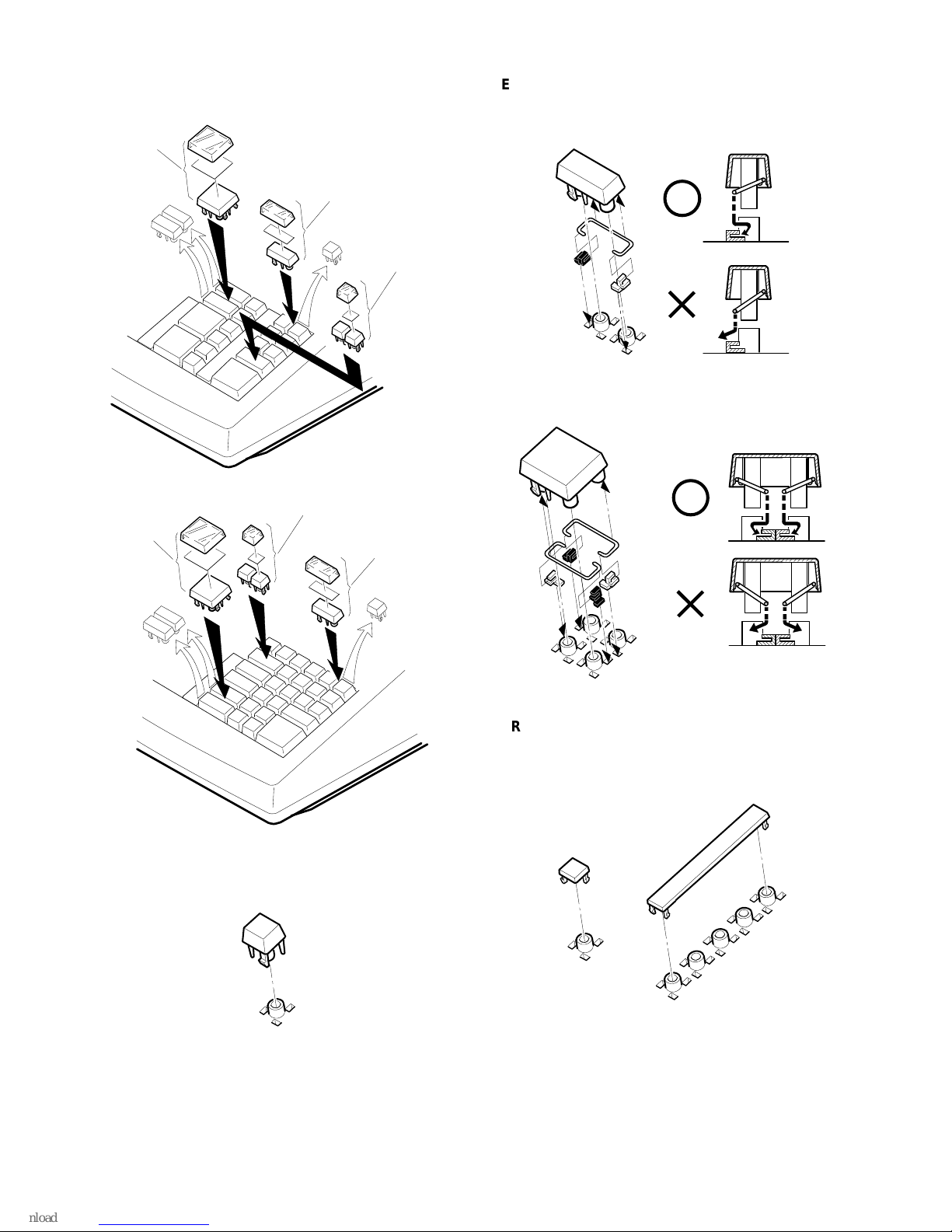
2. Installation proced ure
1
ER-11KT7
2
ER-12KT7, ER-22KT7
Note: Th ere are bla ck spa cer s and white spacers. Refer to the figure
before for attaching them.
• Attach the black spacer to the left lower side, and the white spacer
to the right lower side.
3
ER-11DK7, ER-51DK7
ER-12KT7
ER-11KT7
ER-22KT7
ER-12KT7
ER-11KT7
ER-22KT7
9
 Loading...