

Page 1

MODEL:
DX-C310
DX-C311
DX-C380
DX-C381
DIGITAL FULL COLOUR MULTIFUNCTIONAL SYSTEM
Maintenance & Safety GuideMaintenance & Safety GuideMaintenance & Safety Guide
Please read first
Please read this guide first to ensure safe
use of the machine.
Before installing this product, be sure to
read the "TO ENSURE SAFE USE OF THE
MACHINE" and "INSTALLATION
REQUIREMENTS" sections.
TO ENSURE SAFE USE
OF THE MACHINE
INSTALLATION
REQUIREMENTS
Keep this manual close at hand
for reference whenever needed.
SUPPLIES
REPLACING SUPPLIES AND
MAINTENANCE
TROUBLESHOOTING
SPECIFICATIONS
INFORMATION ON DISPOSAL
TO THE ADMINISTRATOR
OF THE MACHINE
Page 2
Caution!
For complete electrical disconnection, pull out the main plug.
The socket-outlet shall be installed near the equipment and shall be easily accessible.
Shielded interface cables must be used with this equipment to maintain compliance
with EMC regulations.
➢➢➣➢➣➢➣➢➣➢➣➢➣➢➣➢➣➢➣➢➣➢➣➢➣➢➣➢➣➢➣➢➣➢➣➢➣➢➣➢➣➢➣➢➣➢➣➢➣➢➣➢➣➢➣
The equipment should be installed near an accessible socket outlet for easy disconnection.
Notice for users in the UK
MAINS
The mains lead of this equipment is already fitted with a mains plug which is either a non-rewireable
(moulded) or a rewireable type. Should the fuse need to be replaced, a BSI or ASTA approved fuse
to BS1362 marked or
be used.
Always refit the fuse cover after replacing the fuse on the moulded plug. Never use the plug without
the fuse cover fitted.
In the unlikely event of the socket outlet in your home not being compatible with the plug supplied
either cut-off the moulded plug (if this type is fitted) or remove by undoing the screws if a rewireable
plug is fitted and fit an appropriate type observing the wiring code below.
DANGER: The fuse should be removed from the cut-off plug and the plug destroyed immediately
and disposed of in a safe manner. Under no circumstances should the cut-off plug be inserted
elsewhere into a 13A socket outlet as a serious electric shock may occur.
To fit an appropriate plug to the mains lead, follow the instructions below:
IMPORTANT: The wires in this mains lead are coloured in accordance with the following code:
As the colours of the wires in this mains lead may not correspond with coloured markings
identifying the terminals in your plug, proceed as follows:
The wire which is coloured GREEN-AND-YELLOW must be connected to the terminal in the plug
which is marked with the letter E, or by the safety earth symbol
and-yellow.
The wire which is coloured BLUE must be connected to the terminal which is marked with the letter
N or coloured black.
The wire which is coloured BROWN must be connected to the terminal which is marked with the
letter L or coloured red.
If you have any doubt, consult a qualified electrician.
WARNING: THIS APPARATUS MUST BE EARTHED.
➣➢➣➢➣➢➣➢➣➢➣➢➣➢➣➢➣➢➣➢➣➢➣➢➣➢➣➢➣➢➣➢➣➢➣➢➣➢➣➢➣➢➣➢➣➢➣➢➣➢
PLUG WIRING INSTRUCTIONS
and of the same rating as the one removed from the plug must
GREEN-AND-YELLOW: Earth
BLUE: Neutral
BROWN: Live
Å@, or coloured green or green-
➢➣➢➣➢➣➢➣➢➣➢➣➢➣➢➣➢➣➢➣➢➣➢➣➢➣➢➣➢➣➢➣➢➣➢➣➢➣➢➣➢➣➢➣➢➣➢➣➢➣➢➣➢➣
➢➣➢➣➢➣➢➣➢➣➢➣➢➣➢➣➢➣➢➣➢➣➢➣➢➣➢➣➢➣➢➣➢➣➢➣➢➣➢➣➢➣➢➣➢➣➢➣➢➣➢➣➢➣➢
This machine contains the software having modules developed by Independent JPEG
Group.
This product includes Adobe
®
Flash® technology of Adobe Systems Incorporated.
Copyright© 1995-2007 Adobe Macromedia Software LLC. All rights reserved.
Page 3

EMC (this machine and peripheral devices)
Warning:
This is a Class A product. In a domestic environment this product may cause radio
interference in which case the user may be required to take adequate measures.
For the users of the fax function
FAX interface cable and Line cable:
These special accessories must be used with the device.
The Declaration of Conformity can be viewed at the following URL address.
http://www.sharp.de/doc/MX-FXX3.pdf
1
Page 4

Contents
TO ENSURE SAFE USE OF THE
MACHINE . . . . . . . . . . . . . . . . . . 4
Cautions . . . . . . . . . . . . . . . . . . . 4
Warnings . . . . . . . . . . . . . . . . . . 5
Laser information . . . . . . . . . . . . 7
INSTALLATION REQUIREMENTS . . .
SUPPLIES. . . . . . . . . . . . . . . . . 10
Storage of supplies. . . . . . . . . . 10
Supply of spare parts and
consumables . . . . . . . . . . . . . . 11
REPLACING SUPPLIES AND
MAINTENANCE . . . . . . . . . . . . 12
Replacement time for supplies. 12
Supplies . . . . . . . . . . . . . . . . . . 13
Replacing the toner cartridges . 14
Replacing the toner collection
container. . . . . . . . . . . . . . . . . . 19
Replacing the developer cartridge /
drum cartridge. . . . . . . . . . . . . . . . .
Replacing the developer cartridge . .
Colour balance adjustments. . . 31
Replacing the drum cartridge . . 32
Replacing the transfer unit . . . . 35
Replacing the primary transfer
belt unit. . . . . . . . . . . . . . . . . . . 35
Replacing the secondary transfer
roller unit. . . . . . . . . . . . . . . . . . 41
Replacing the fusing unit / ozone
filter. . . . . . . . . . . . . . . . . . . . . . 45
Replacing the fusing unit . . . . . 45
Replacing the ozone filter. . . . . 50
Replacing the staple cartridge
in the finisher . . . . . . . . . . . . . . 52
Regular maintenance . . . . . . . . 55
Cleaning the document glass and
automatic document feeder. . . . .
23
23
55
Cleaning the main charger of the
photoconductive drum . . . . . . . 56
Cleaning and replacing the rollers . .
Cleaning and replacing paper
cassette rollers . . . . . . . . . . . . . 61
8
Cleaning and replacing the
bypass tray rollers . . . . . . . . . . 66
Cleaning and replacing the automatic
document feeder rollers . . . . . . . . . . .
Cleaning the laser unit . . . . . . . 78
Cleaning the PT charger of the
primary transfer belt unit . . . . . . 85
Executing the fusing cleaning
mode. . . . . . . . . . . . . . . . . . . . . 88
TROUBLESHOOTING . . . . . . . 89
When an error code appears . . 89
Checking the status of the machine. .
SPECIFICATIONS . . . . . . . . . . 92
Machine specifications / copier
specifications . . . . . . . . . . . . . . 92
Continuous copying speeds . . . 96
Ambient environment . . . . . . . . 96
Acoustic noise emission
(measurement according to
ISO7779) . . . . . . . . . . . . . . . . . 97
Automatic document feeder
specifications . . . . . . . . . . . . . . 97
Business card feeder specifications. .
500-sheet paper feed unit
specifications . . . . . . . . . . . . . . 98
Finisher specifications . . . . . . . 99
Printer specifications . . . . . . . 101
Network scanner / Internet Fax
specifications . . . . . . . . . . . . . 102
Pull scan function (TWAIN)
specifications . . . . . . . . . . . . . 103
Facsimile specifications . . . . . 104
61
72
91
98
2
Page 5

INFORMATION ON DISPOSAL . .
A. Information on Disposal for
Users (private households) . . 106
B. Information on Disposal for
Business Users. . . . . . . . . . . . 107
Note:
• Considerable care has been taken in preparing this manual. If you have any
comments or concerns about the manual, please contact your dealer or nearest
SHARP Service Department.
• This product has undergone strict quality control and inspection procedures. In the
unlikely event that a defect or other problem is discovered, please contact your
dealer or nearest SHARP Service Department.
• Aside from instances provided for by law, SHARP is not responsible for failures
occurring during the use of the product or its options, or failures due to incorrect
operation of the product and its options, or other failures, or for any damage that
occurs due to use of the product.
106
TO THE ADMINISTRATOR OF
THE MACHINE . . . . . . . . . . . . 110
Factory default passwords . . . 110
Forwarding all transmitted and
received data to the administrator
(document administration function)
For the users of the fax function . .
Trademark acknowledgments . .
. 110
111
112
Products that have earned the ENERGY STAR® are designed to
protect the environment through superior energy efficiency.
The products that meet the ENERGY STAR® guidelines carry the logo shown
above.
The products without the logo may not meet the ENERGY STAR
®
guidelines.
Warranty
While every effort has been made to make this document as accurate and helpful as possible,
SHARP Corporation makes no warranty of any kind with regard to its content. All information
included herein is subject to change without notice. SHARP is not responsible for any loss or
damages, direct or indirect, arising from or related to the use of this operation manual.
©Copyright SHARP Corporation 2008. All rights reserved. Reproduction,
adaptation or translation without prior written permission is prohibited, except as
allowed under copyright laws.
3
Page 6

TO ENSURE SAFE USE OF THE MACHINE
Cautions
• Do not make any modifications to
this machine.
Doing so may result in personal
injury or damage to the machine.
• Do not make copies of anything
which is prohibited from copying
by law.
The following items are normally
prohibited from printing by national
law. Other items may be prohibited
by local law.
●
Money ● Stamps ● Bonds
●
Stocks ● Bank drafts ● Checks
●
Passports ● Driver's licences
• Do not use a flammable spray to
clean the machine.
If gas from the spray comes in
contact with hot electrical
components or the fusing unit inside
the machine, fire or electrical shock
may result.
• Do not place a vessel that
contains water or other liquid on
the machine.
Do not place metal objects on the
machine that may fall into the
machine.
• In the event that a metal object
falls or liquid spills into the
machine, first turn off the
machine's main power switch
and then unplug the power cord.
• If a thunderstorm begins, turn off
the machine's main power switch
and unplug the power cord in
order to prevent electrical shock
and fire due to a lightning strike.
• If you see condensation on the
surface of the machine or on the
display, open the front cover and
right side cover and make sure
there is no condensation on the
inside of the machine. Also
check the area inside the front
cover that is hidden by the toner
collection container.
If condensation has formed inside
the machine, turn off the main
power. Turning on the main power
when condensation has formed
inside the machine may cause a
failure. Leave the cover open until
the condensation evaporates
naturally.
To keep foreign matter from getting
on the primary transfer belt unit or
secondary transfer roller unit while
the right cover is open, place a
cover over the opening.
• Do not plug in or unplug the
power cord with a wet hand.
• The machine emits a slight
amount of electromagnetic
radiation.
If you are using a pacemaker and
notice an abnormal feeling,
distance yourself from the machine.
If necessary, consult a doctor.
4
Page 7
Warnings
• Do not touch the transfer belt
and the transfer roller.
Scratches or smudges on the
transfer belt or transfer roller will
cause dirty prints.
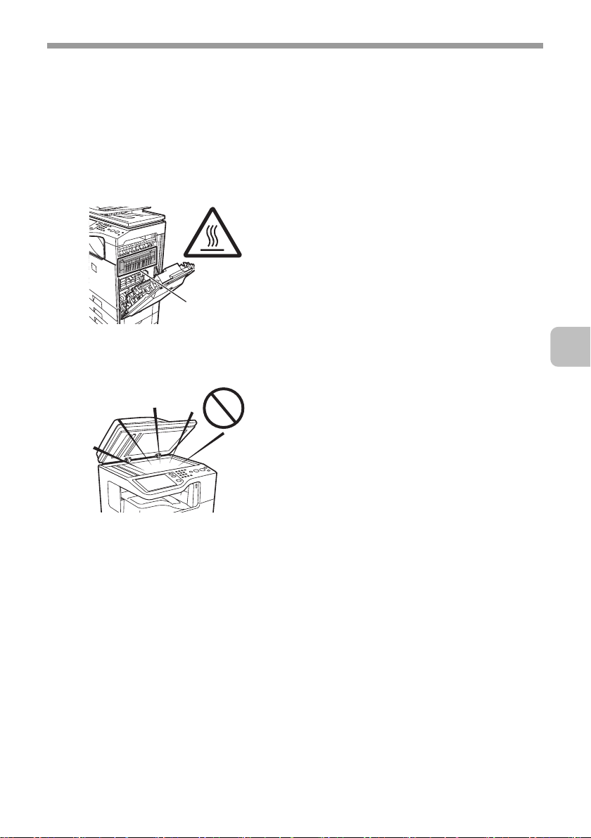
• The fusing unit is extremely hot.
Exercise care in this area.
Fusing unit
• Do not look directly at the light
source.
Doing so may damage your eyes.
TO ENSURE SAFE USE OF THE MACHINE
• Store toner, toner containers
(toner cartridges), and toner
collection containers out of the
reach of children.
• Do not place the machine on a
wobbly, slanted, or unstable
surface.
Install the machine only on a
surface that can withstand the
weight of the machine.
• When unplugging the power
cord, do not grasp and pull on
the cord.
• The machine is heavy.
Firmly grasp the moving handles so
that they do not slip out of your
hands. To prevent injury when
moving the machine, it is
recommended that it be moved by
four or more persons.
• Do not throw toner, a toner
container (toner cartridge), or a
toner collection container into a
fire.
Toner may fly and cause burns.
5
Page 8

TO ENSURE SAFE USE OF THE MACHINE
The machine includes the document filing function, which stores document image data
on the machine's hard drive. Stored documents can be called up and printed or
transmitted as needed. If a hard drive failure occurs, it will no longer be possible to call
up the stored document data. To prevent the loss of important documents in the
unlikely event of a hard drive failure, keep the originals of important documents or store
the original data elsewhere.
With the exception of instances provided for by law, Sharp Corporation bears no
responsibility for any damages or loss due to the loss of stored document data.
"BATTERY DISPOSAL"
THIS PRODUCT CONTAINS A LITHIUM PRIMARY MEMORY BACK-UP BATTERY
THAT MUST BE DISPOSED OF PROPERLY. PLEASE CONTACT YOUR LOCAL
SHARP DEALER OR AUTHORISED SERVICE REPRESENTATIVE FOR
ASSISTANCE IN DISPOSING OF THIS BATTERY.
Each instruction also covers the optional units used with these products.
6
Page 9
Laser information
Wave length 790 nm ±10 nm
TO ENSURE SAFE USE OF THE MACHINE
Pulse times
(North America and Europe)
Output power Max 0.6 mW (LD1+ LD2)
Caution
Use of controls or adjustments or performance of procedures other than those specified
herein may result in hazardous radiation exposure.
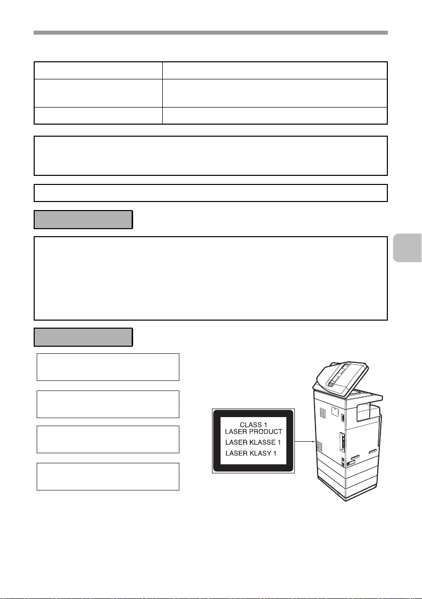
This Digital Equipment is CLASS 1 LASER PRODUCT (IEC 60825-1 Edition 1.2-2001)
4.1 µs ±4.1 ns /7 mm
For North America:
SAFETY PRECAUTIONS
This Digital Equipment is rated Class 1 and complies with 21 CFR 1040.10 and
1040.11 of the CDRH standards. This means that the equipment does not produce
hazardous laser radiation. For your safety, observe the precautions below.
• Do not remove the cabinet, operation panel or any other covers.
• The equipment's exterior covers contain several safety interlock switches. Do not
bypass any safety interlock by inserting wedges or other items into switch slots.
For Europe:
CLASS 1 LASER PRODUCT
LASER KLASSE 1
LUOKAN 1 LASERLAITE
KLASS 1 LASERAPPARAT
7
Page 10
INSTALLATION REQUIREMENTS
Improper installation may damage this product. Please note the following during
initial installation and whenever the machine is moved.
1. The machine should be installed
near an accessible power outlet for
easy connection.
2. Be sure to connect the power cord
only to a power outlet that meets
the specified voltage and current
requirements. Also make certain
the outlet is properly grounded.
• For the power supply
requirements, see the name plate
in the lower left corner of the left
side of the machine.
Connect the machine to a power
outlet which is not used for other
electric appliances. If a lighting
fixture is connected to the same
outlet, the light may flicker.
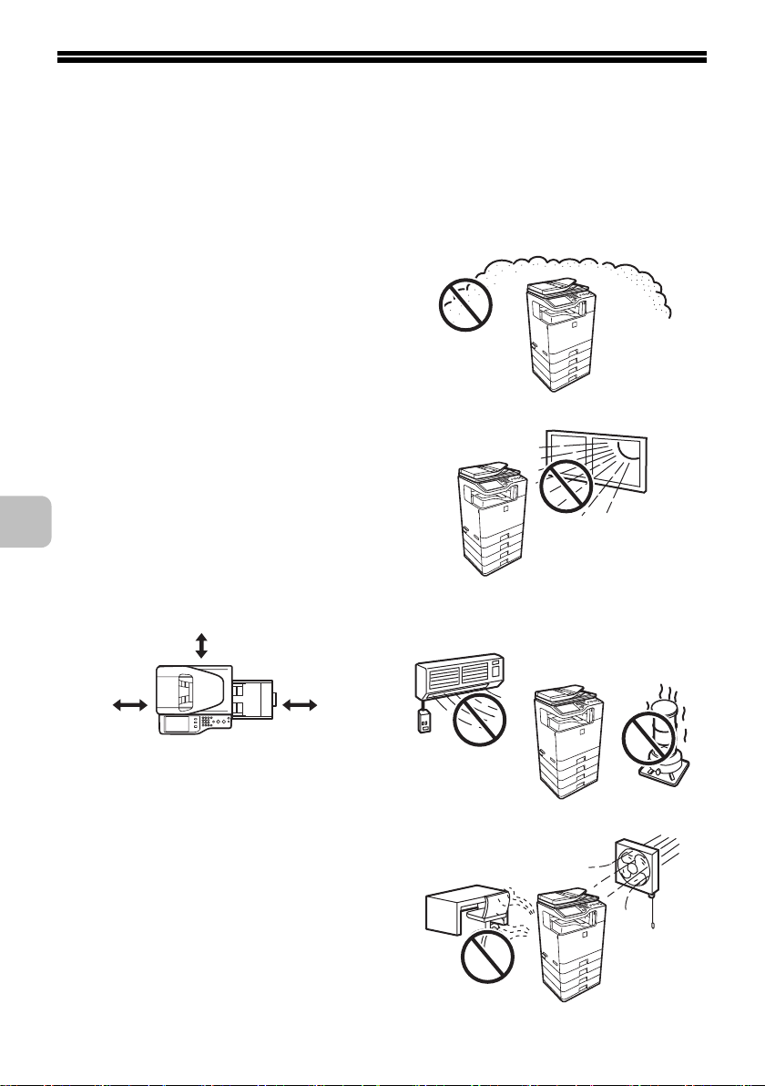
3. Be sure to allow the required space
around the machine for servicing
and proper ventilation.
30 cm
(11-13/16")
30 cm
(11-13/16")
45 cm
(17-23/32")
6. Do not install the machine in areas
that are:
• damp, humid, or very dusty
• exposed to direct sunlight
z
• subject to extreme temperature
or humidity changes, e.g., near
an air conditioner or heater
4. The machine includes a built-in
hard drive. Do not subject the
machine to shock or vibration. In
particular, never move the machine
while the power is on.
5. The installation surface must be
level and rigid. If the machine is
operated when tilted at an angle,
failure may result.
8
• poorly ventilated.
Page 11

INSTALLATION REQUIREMENTS
CAUTION:
Do not install the machine in a location with poor air circulation.
A small amount of ozone is created inside the machine during printing. The amount of
ozone created is not sufficient to be harmful; however, an unpleasant odor may be
noticed during large copy runs, and thus the machine should be installed in a room with
a ventilation fan or windows that provide sufficient air circulation. (The odor may
occasionally cause headaches.)
* Install the machine so that people are not directly exposed to exhaust from the
machine. If installed near a window, ensure that the machine is not exposed to direct
sunlight.
9
Page 12

SUPPLIES
As you use the machine, it will become necessary to replace supplies such as
paper and toner cartridges.
Be sure to use SHARP-specified supplies, including paper and toner cartridges.
For best copying results, be sure to use only Sharp Genuine
Supplies which are designed, engineered, and tested to
maximize the life and performance of Sharp products. Look for
the Genuine Supplies label on the toner package.
GENUINE SUPPLIES
Storage of supplies
Proper storage
1. Store the supplies in a location that is:
• clean and dry
• at normal temperature with minimal temperature fluctuations
• not exposed to direct sunlight
2. Store paper in the wrapper and lying flat.
3. Paper stored in packages standing up or out of the wrapper may curl or
become damp, resulting in paper misfeeds.
Storing toner cartridges or developer cartridges
Store the box that contains the toner cartridge or developer cartridge
horizontally; do not store it standing up. If the toner cartridge or developer
cartridge is stored standing up, the toner or developer may solidify inside the
cartridge.
Store the toner cartridge or developer cartridge in a location that is cooler than
40°C (104°F). Storage in a hot location may cause the toner or developer in the
cartridge to solidify.
Storing drum cartridges
Store the box that contains the drum cartridge horizontally; do not store it
standing up.
Store the drum cartridge in a location that is cooler than 40°C (104°F). Storage
in a hot location may cause failure.
Staple cartridge
The finisher requires the following staple cartridge:
MX-SCX1 (for finisher)
Approx. 5000 per cartridge x 3 cartridges
10
Page 13

SUPPLIES
Supply of spare parts and consumables
The supply of spare parts for repair of the machine is guaranteed for at least 7
years following the termination of production. Spare parts are those parts of the
machine which may break down within the scope of the ordinary use of the
product, whereas those parts which normally exceed the life of the product are
not to be considered as spare parts. Consumables too, are available for 7 years
following the termination of production.
11
Page 14
REPLACING SUPPLIES AND
MAINTENANCE
This section explains the procedures for replacing supplies such as toner and
staple cartridges and routine maintenance.
Replacement time for supplies
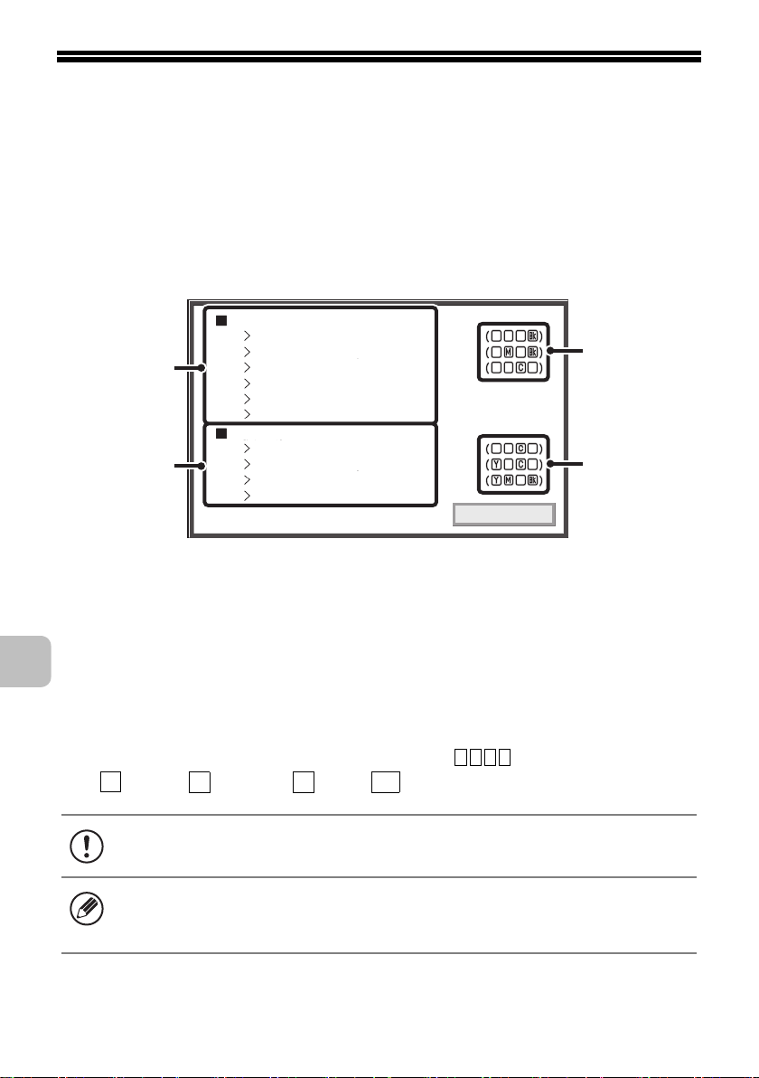
When it is time to replace a supply item, a message will appear in the display.
Change the supplies.
Toner Cartridge
Developer Cartridge
(1)
(2)
Drum Cartridge
Primary Transfer Belt Unit
Secondary Transfer Roller Unit
Toner Collection Container
The supplies will be needed soon.
Toner Cartridge
Developer Cartridge
Drum Cartridge
Fusing Unit
OK
(1) The item requiring replacement will be indicated.
Replace the item when this message appears.
(3)
(3)
(2) A supply item that will soon require replacement is displayed.
When this message appears, obtain a new item and have it ready for replacement
whenever necessary.
(3) For items such as toner cartridges, developer cartridges, and
drum cartridges that come in different colours, the colour that
is low or has run out is indicated in "( )"
Y
: Yellow, : Magenta, : Cyan, : Black
When a message prompting you to replace a supply item appears, replace the
item promptly.
• You can also check supply replacement times in the Web page.
• Registration is performed in [Device Status] in [Machine Identification] in the
M C
Web page menu.
Bk
12
Page 15
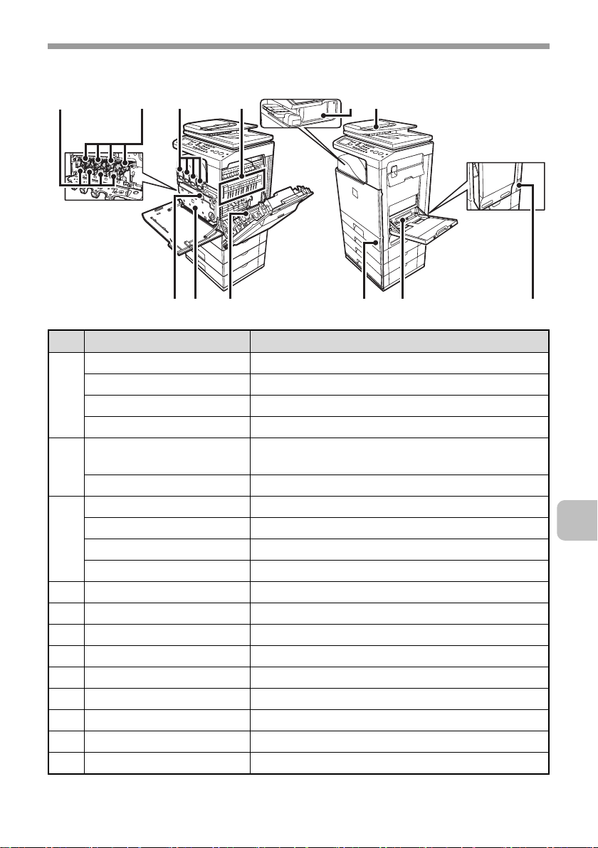
Supplies
REPLACING SUPPLIES AND MAINTENANCE
(1)
(3)(2) (4) (5) (6)
(8) (11)(7) (9) (10) (12)
No. Model Name
(1) MX-C40NVB Developer cartridge (black)
MX-C40NVC Developer cartridge (cyan)
MX-C40NVM Developer cartridge (magenta)
MX-C40NVY Developer cartridge (yellow)
(2) MX-C40NRB Drum cartridge (black) (including main charger
cleaner)
MX-C40NRS Drum cartridge (colour)
(3) DX-C40NTB Toner cartridge (black)
DX-C40NTC Toner cartridge (cyan)
DX-C40NTM Toner cartridge (magenta)
DX-C40NTY Toner cartridge (yellow)
(4) MX-C31FU1 Fusing unit (including ozone filter)
(5) MX-SCX1 Staple cartridge
(6) MX-C31DF DF roller kit
(7) MX-C31U1 Primary transfer belt unit
(8) MX-C31HB Toner collection container
(9) MX-C31U2 Secondary transfer roller unit
(10) MX-C31RT Feeding roller kit
(11) MX-C31MR MF feeding roller kit
(12) MX-C31FU1 Ozone filter (included in the fusing unit package)
13
Page 16
REPLACING SUPPLIES AND MAINTENANCE
Replacing the toner cartridges
When it is time to replace a supply item, a message instructing you to replace
the item will appear in the display.
When replacing a toner cartridge, carefully check the indicated colour and
replace the toner cartridge for that colour.
• Do not replace a supply item before the replacement message appears in the
display.
• After using up a cartridge, pack it with the packing case, packing material and
bag that are used for the original cartridge.
Open the front cover.
Locations of colour toner cartridges
1
(M)(Y) (C) (Bk)
14
(Y): Yellow (M): Magenta
(C): Cyan (Bk): Black
Page 17
REPLACING SUPPLIES AND MAINTENANCE
Pull the toner cartridge toward you.
Example: Replacing the yellow toner cartridge
2
Take out the new toner cartridge, hold it with both
hands, and shake 5 or 6 times horizontally.
Protective
material
3
• When shaking the toner cartridge, be sure to shake with the protective
material inserted in the cartridge. If you shake the cartridge after
removing the protective material, toner may spill out.
• Shake the toner cartridge only in the horizontal direction. If shaken in
any other direction, toner may collect in one part of the cartridge.
15
Page 18
REPLACING SUPPLIES AND MAINTENANCE
Remove the protective material from the new toner
cartridge.
4
• Hold the toner cartridge firmly while removing the protective material.
• After the protective material has been removed, do not point the toner
cartridge down or shake it. Toner may spill out.
Insert the new toner cartridge horizontally and
push it firmly in.
The shape of the toner cartridge varies by colour. Insert in the same location as
the toner cartridge that was removed.
16
5
Page 19
REPLACING SUPPLIES AND MAINTENANCE
Close the front cover.
6
• Before moving the machine, remove the toner cartridge. Moving the
machine with the toner cartridge installed may cause a failure.
• When the developer cartridge has been removed, do not remove or
insert the toner cartridge. This may cause a failure.
• After the toner cartridge is replaced, the machine automatically enters
image adjustment mode. Image adjustment will not take place if the
cover is not closed.
• Take care that your fingers are not pinched when closing the cover.
Caution
• Do not throw a toner cartridge into a fire. Toner may fly and cause burns.
• Store toner cartridges out of the reach of small children.
• Store the box that contains the toner cartridge horizontally; do not store it
standing up. If the toner cartridge is stored standing up, the toner may solidify
inside the cartridge.
Store the toner in a location that is cooler than 40°C (104°F). Storage in a hot
location may cause the toner in the cartridge to solidify.
• If a toner cartridge other than a SHARP-recommended toner cartridge is
used, the machine may not attain full quality and performance and there is a
risk of damage to the machine. Be sure to use a SHARP-recommended
toner cartridge.
• Place the old toner cartridge in the bag that contained the new toner
cartridge, seal the bag, and place it in the box.
17
Page 20

REPLACING SUPPLIES AND MAINTENANCE
• Keep the used toner cartridge in a plastic bag (do not discard it).
•
To view the approximate amount of
toner remaining, continually touch
the [COPY] key during printing or
when the machine is idle. The
percentage of toner remaining will
appear in the display while the key
is touched. When the percentage
falls to "25-0%", obtain a new toner cartridge and keep it ready for replacement.
When the remaining toner falls to "25-0%", colours in the output may be faint or
partially missing when an original or image with dark colours is copied or
printed.
Total Count B/W:00,000,000
Full Colour:00,000,000
2-colour:00,000,000
Single colour:00,000,000
Toner Quantity [Bk]:100-75%
[C]:100-75%
[M]:100-75%
[Y]:100-75%
18
Page 21
REPLACING SUPPLIES AND MAINTENANCE
Replacing the toner collection container
The toner collection container collects excess toner that is produced during printing.
When it is time to replace a supply item, a message instructing you to replace
the item will appear in the display. Follow the procedure below to replace the
toner collection container. It is also necessary to remove the toner collection
container in order to replace the transfer unit. Refer to the procedure below to
remove the toner collection container when replacing the transfer unit.
• Do not subject the toner collection container to shock. The amount of
collected toner may be incorrectly detected and cause machine failure.
• Do not replace a supply item before the replacement message appears in the
display.
• Toner may spill when the toner collection container is replaced. Before
replacing the toner collection container, take measures such as placing
covers on and around the machine to prevent soiling.
Open the front cover.
1
19
Page 22
REPLACING SUPPLIES AND MAINTENANCE
Release the used toner collection container.
(1) Turn the toner collection container lock lever to the
right until it is horizontal.
2
(2) Tip the toner collection container forward.
Grasp the toner collection container with both hands at the marks on the upper
right and lower left of the container and slowly tip the container toward you.
Mark
Mark
20
Remove the toner collection container.
3
• If the toner collection container is tipped forward too far, it will not be
possible to remove it.
• Do not point the holes down as used toner will spill out.
• Hold the container by both hands and lift it up slowly.
• Do not discard the toner collection container. Place it in a plastic bag
and keep it until it is collected by a service.
Page 23
REPLACING SUPPLIES AND MAINTENANCE
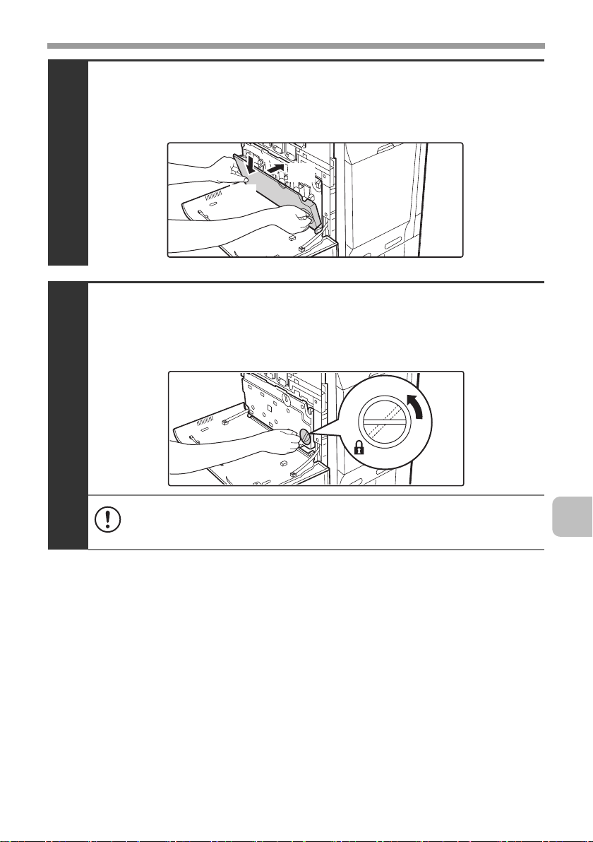
Install the new toner collection container.
Insert the container from above at a slant. (The direction opposite to when you
removed it.)
4
(2)
(1)
Turn the lock lever on the toner collection
container to the left.
Turn the lock lever to the left until it stops.
5
If the lock lever does not turn, check if the toner collection container is
installed correctly. In particular, make sure that the top left corner of the
toner collection container is correctly in place.
21
Page 24
REPLACING SUPPLIES AND MAINTENANCE
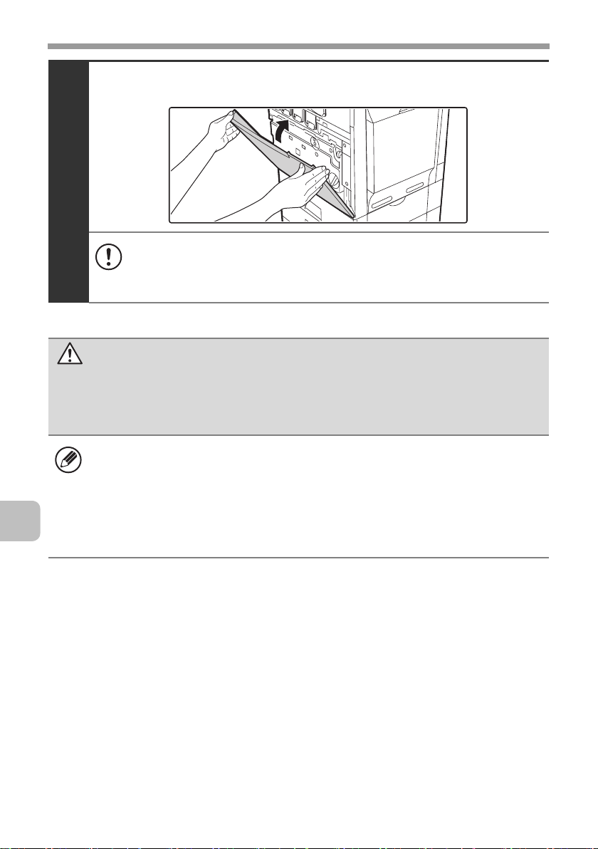
Close the front cover.
6
• If the toner collection container is tipped forward too far, it will not be
possible to remove it.
• Do not point the holes down as used toner will spill out.
• Take care that your fingers are not pinched when closing the cover.
Caution
• Do not throw the toner collection container into a fire. Toner may fly and
cause burns.
• Store the toner collection container out of the reach of small children.
22
• Place the old toner collection container in the bag that contained the new
toner collection container, seal the bag, and place it in the box.
• Toner may spill when the toner collection container is replaced. Take
measures so that there will be no problem if toner spills on the machine,
around the machine, or on your clothes.
• Do not touch the part soiled with toner of the removed toner collection
container. If you accidentally touch the toner, immediately wash your hands.
Page 25
REPLACING SUPPLIES AND MAINTENANCE
Replacing the developer cartridge / drum cartridge
Before replacing the developer cartridge or drum cartridge, turn off the main
power of the machine and wait briefly.
Replacing the developer cartridge
When it is time to replace a supply item, a message instructing you to replace
the item will appear in the display. When replacing a developer cartridge,
carefully check the indicated colour and replace the developer cartridge for that
colour.
It is also necessary to remove the developer cartridge in order to replace the
drum cartridge. Refer to the procedure below to remove the developer cartridge
when replacing the drum cartridge.
Do not replace a supply item before the replacement message appears in the
display.
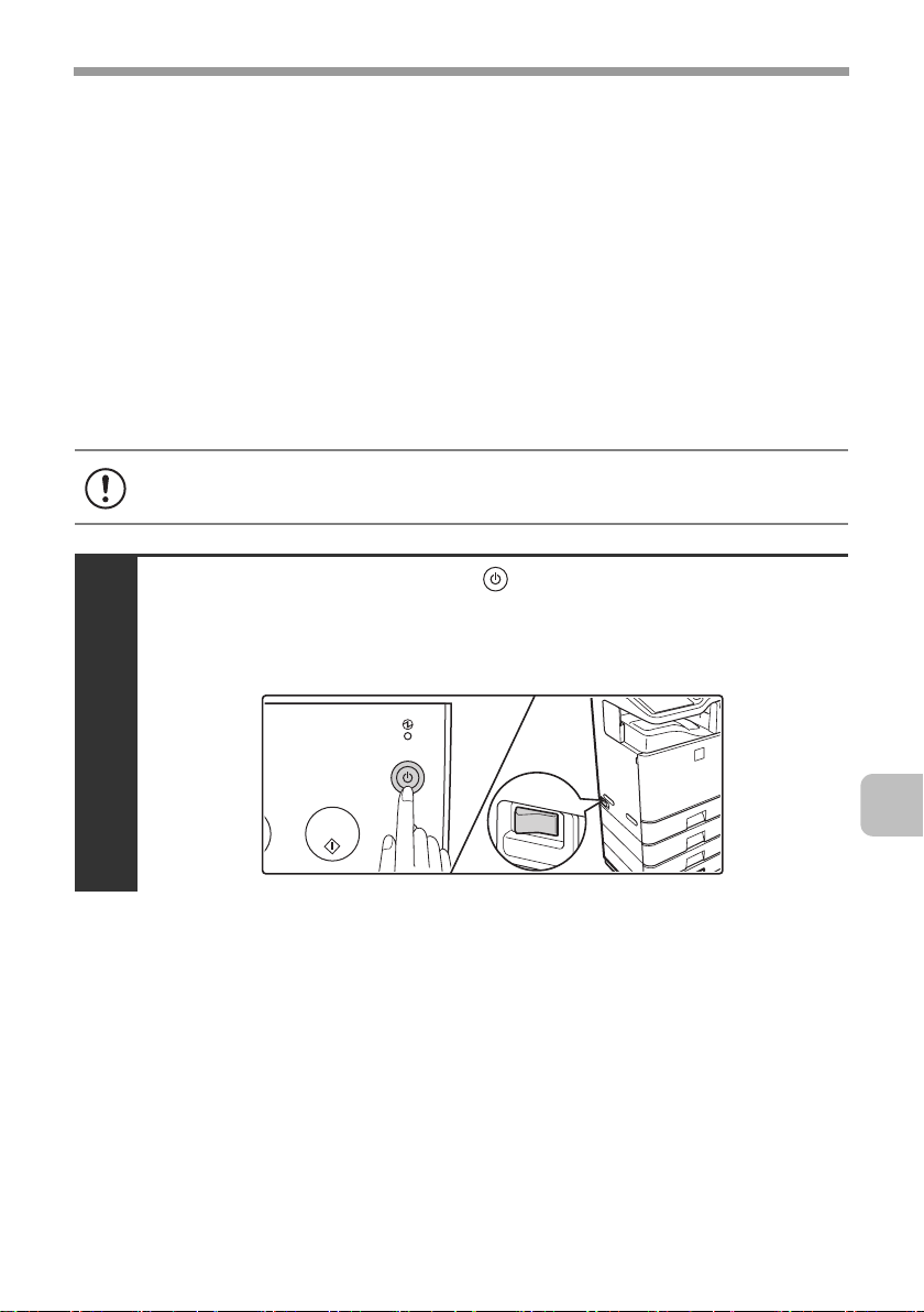
Press the [POWER] key ( ) on the operation panel
to turn off the panel power, and then switch the
main power switch to the off position.
1
23
Page 26
REPLACING SUPPLIES AND MAINTENANCE
Open the front cover and remove the toner
collection container.
☞ Replacing the toner collection container (page 19)
2
Do not point the holes down as used toner will spill out.
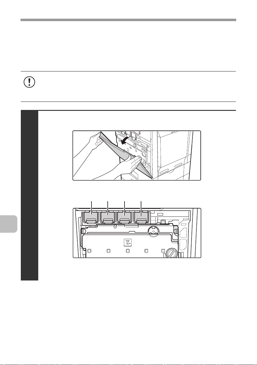
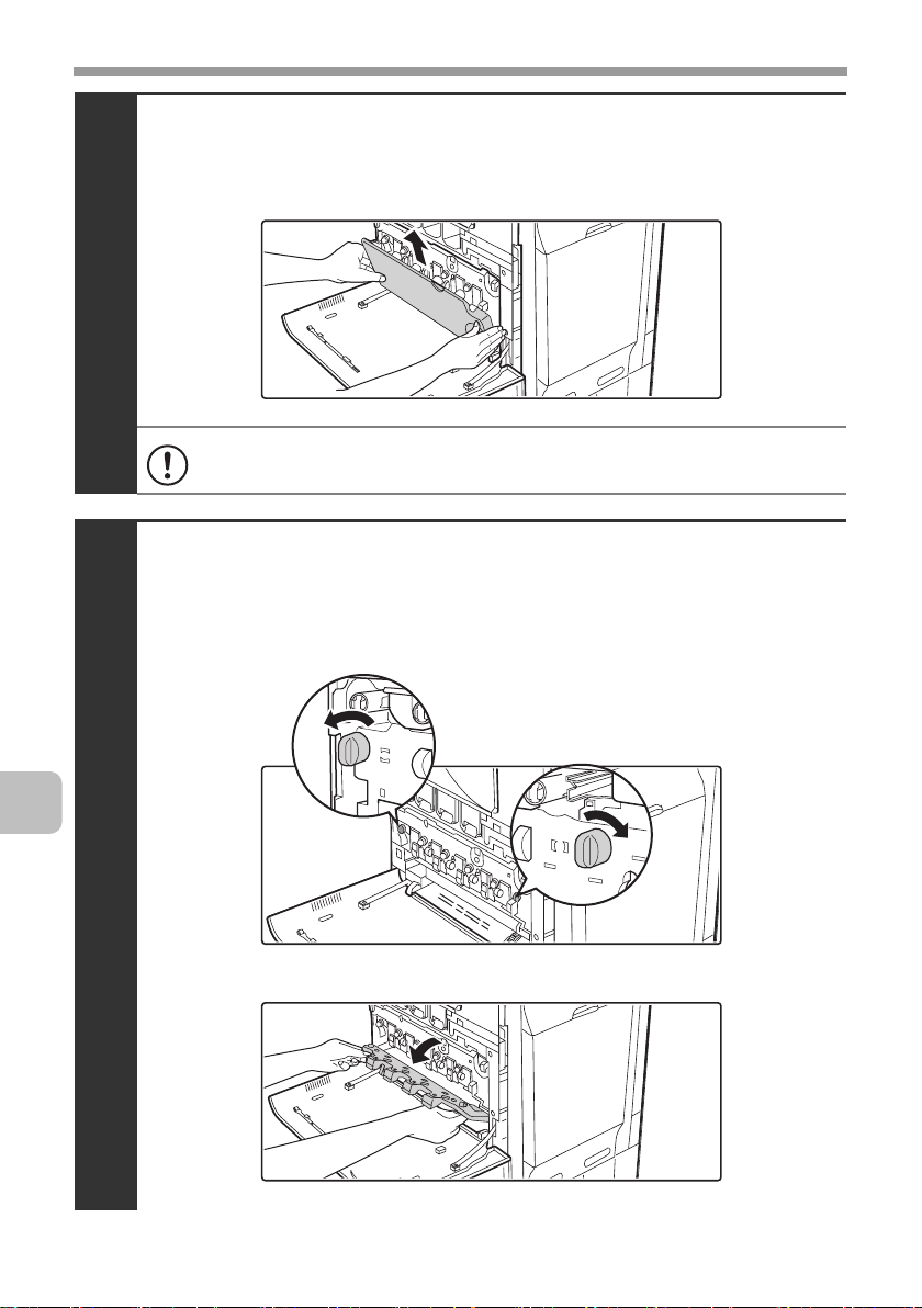
Open the main charger cover.
(1) Turn the main charger cover lock levers in the direction
of an arrow below.
When the lock levers are horizontal, the lock is released.
24
3
(2) Grasp the lock levers and tip the cover forward.
Page 27
REPLACING SUPPLIES AND MAINTENANCE
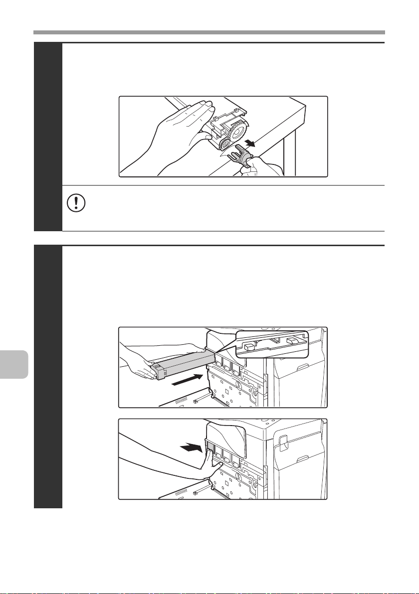
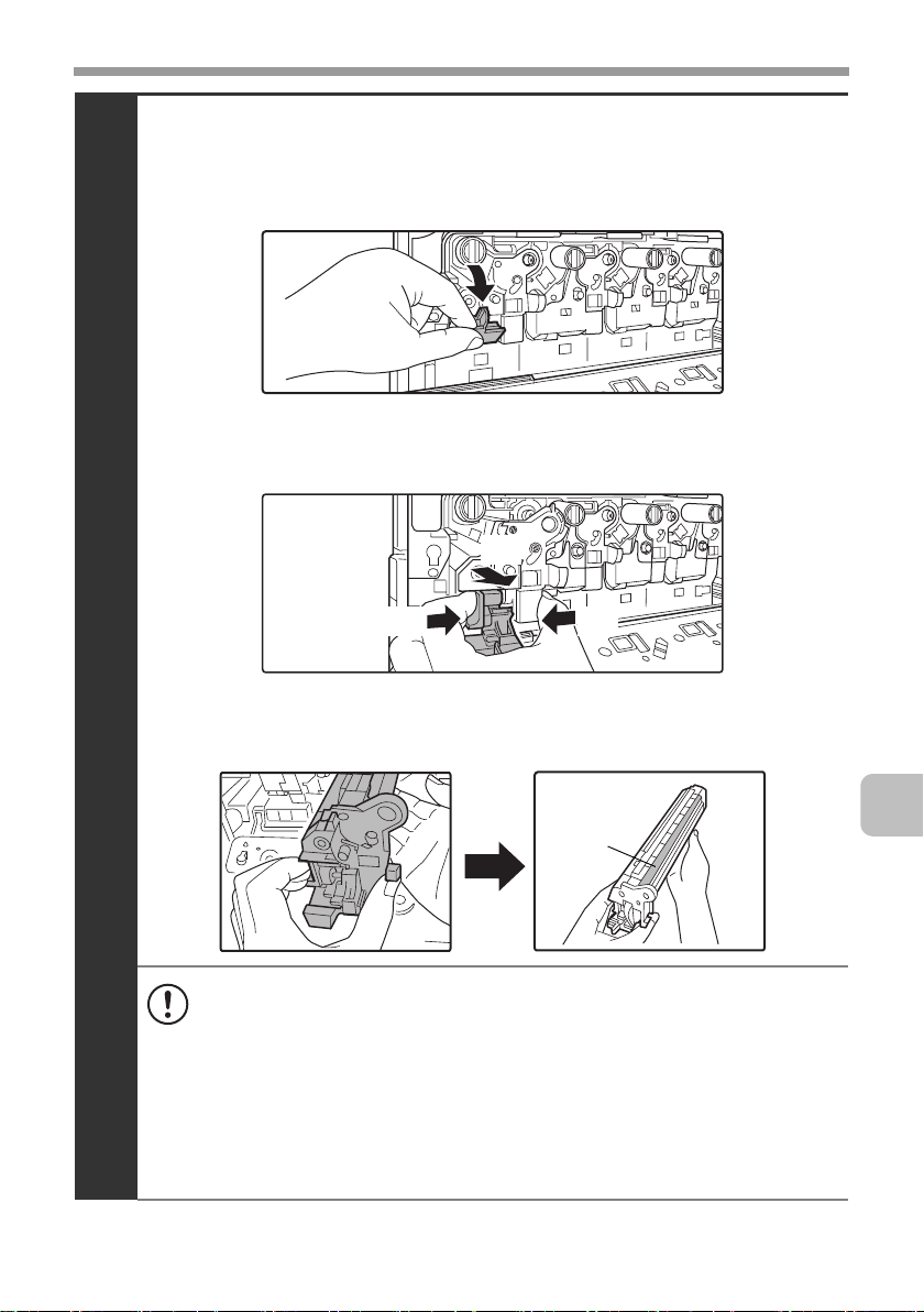
Remove the developer cartridge.
(1) Grasp the developer cartridge lock and pull it forward
and down.
(2) Squeeze the lever on the developer cartridge
(3) Pull the developer cartridge out horizontally.
(3)
(2) (2)
4
(4)
Support the developer cartridge near the middle with your
hand and completely remove the developer cartridge.
Roller
• When removing the developer cartridge, grasp it with both hands at
the middle.
• Try to keep the developer cartridge horizontal as you remove it. If
tipped during removal, developer may spill out.
• There will be toner on the roller area of the removed developer
cartridge. Do not touch the roller area. If you accidentally touch the
toner, immediately wash your hands.
• Place the old developer cartridge in the bag that contained the new
developer cartridge, seal the bag, and place it in the box.
25
Page 28
REPLACING SUPPLIES AND MAINTENANCE
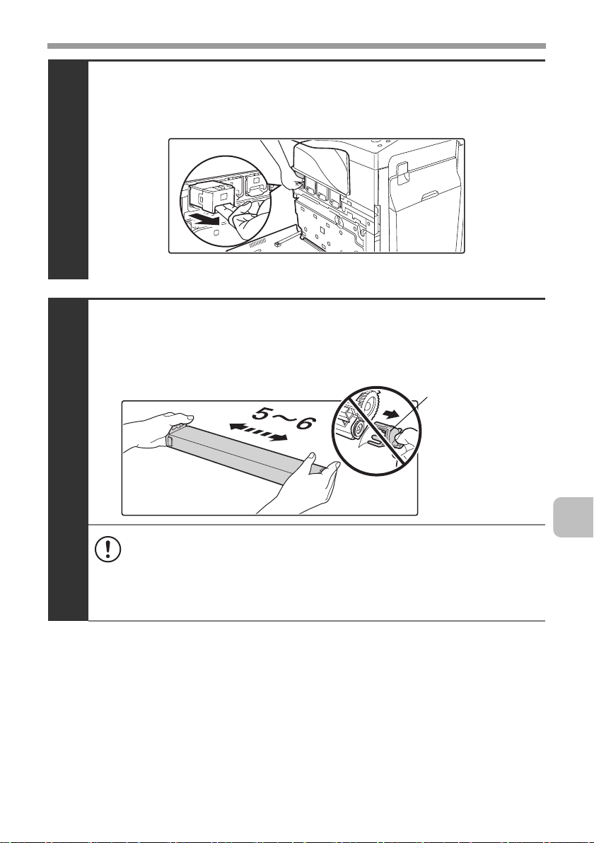
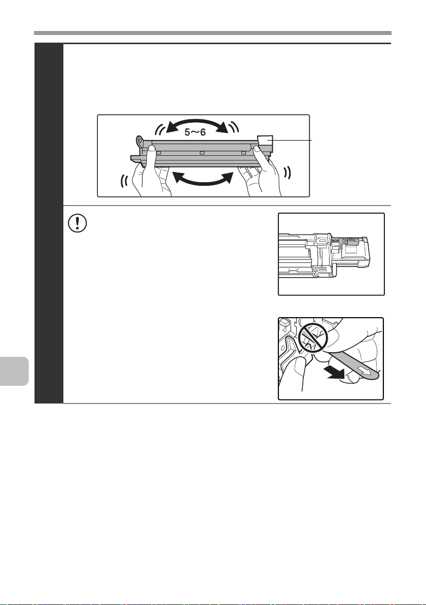
Shake the new developer cartridge 5 or 6 times as shown.
Hold the developer cartridge firmly as shown below and shake forward and
back, left and right.
Remove the protective material after shaking the developer cartridge.
• The part of the developer cartridge
5
shown in the next illustration is easily
deformed or damaged. Do not touch
this part when handling the cartridge.
• Do not touch the roller in the
developer cartridge. If the roller is
accidentally touched, image problems
may result. In that case, replace the
developer cartridge with a new cartridge.
• The seal must not be removed when
shaking the new developer cartridge.
• Take care not to damage the developer
cartridge when shaking it. If damaged,
the developer in the cartridge may leak
out.
Protective
material
26
Page 29
REPLACING SUPPLIES AND MAINTENANCE
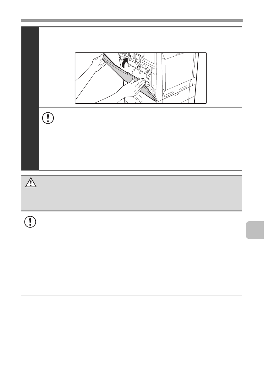
Insert the new developer cartridge horizontally.
Insert the new developer cartridge in the same location as the cartridge that
was removed.
6
• Do not tilt the developer cartridge or insert it in the wrong direction or
orientation. This may damage the developer cartridge or drum
cartridge and cause failure.
• When inserting the developer cartridge, grasp it with both hands at
the middle.
• Do not remove the seal from the developer cartridge until the
cartridge is installed in the machine. If the seal is removed when the
cartridge is not locked, the cartridge may fall out of the machine.
Insert with the arrow on the cartridge aligned with the arrow on the
machine.
Detach the end of the seal from the developer
cartridge.
Align the notch in the seal with the tab on the attachment part and pull up. Be
careful not to completely remove the seal by pulling too hard.
7
27
Page 30
REPLACING SUPPLIES AND MAINTENANCE
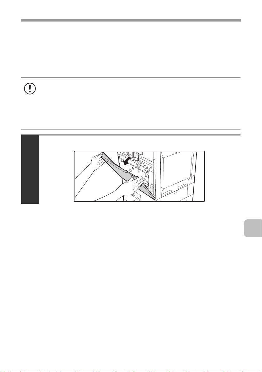
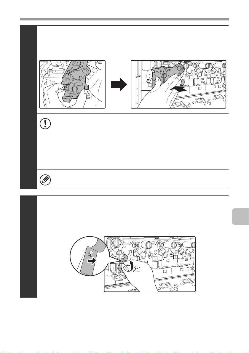
Grasp the developer cartridge lock and replace it
on the machine.
8
Hold the developer cartridge with one hand and
slowly remove the seal with the other hand.
Slowly pull the seal straight and horizontally out.
9
28
If excessive force is used or the seal is pulled out diagonally, it may tear.
There is a mark (red belt) on the end of the seal. After removing the
seal, be sure to verify that the mark (red belt) is on the end of the seal.
If the seal has been cut on the developer cartridge, the cartridge cannot
be used. Replace with a new developer cartridge.
Page 31

REPLACING SUPPLIES AND MAINTENANCE
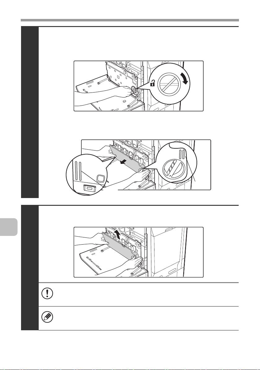
Close the main charger cover and rotate the lock
levers in the direction of the arrows to lock the cover.
When the lock levers are vertical, the cover is locked.
10
Install the toner collection container.
☞ Replacing the toner collection container (page 19)
11
Close the front cover.
12
Take care that your fingers are not pinched when closing the cover.
(2)
(1)
29
Page 32

REPLACING SUPPLIES AND MAINTENANCE
Turn on the power.
Switch the main power switch "ON" and press the [POWER] key ( ) on the
operation panel to turn on the operation panel power.
When replacement is finished, colour balance adjustments begin automatically.
☞ Colour balance adjustments (page 31)
13
Caution
• Do not throw the developer cartridge into a fire. Toner may fly and cause
burns.
• Store the developer cartridge out of the reach of small children.
• When replacing the developer cartridge, be aware that it may soil your
clothes or the immediate surroundings.
• Do not touch the part soiled with toner of the removed toner collection
container. If you accidentally touch the toner, immediately wash your hands.
30
Page 33

REPLACING SUPPLIES AND MAINTENANCE
Colour balance adjustments
When a supply item is replaced, the machine will automatically perform colour
balance adjustments.
The machine performs colour balance adjustments after the following supply
items are replaced:
• Developer cartridge
• Drum cartridge
• Primary transfer belt unit
• Secondary transfer roller unit
After a supply item is replaced, colour balance adjustments begin.
If the replacement message reappears after you have properly replaced an
item, the machine is unable to detect that the item was replaced. Contact your
dealer or nearest authorised service representative.
During colour balance adjustment, do not open the front cover or right cover,
and do not turn off the power. This may cause degraded image quality.
If there is a problem in the colour balance of the output result after a supply
item is replaced, execute auto colour calibration in the system settings.
To adjust the colour balance of the copy function, see "Copy Function
Settings" - "Colour Adjustments" - "Auto Colour Calibration" in "SYSTEM
SETTINGS" of the Operation Guide.
To adjust the colour balance of the print function, see "Printer Settings" - "Auto
Colour Calibration" in "SYSTEM SETTINGS" of the Operation Guide.
31
Page 34

REPLACING SUPPLIES AND MAINTENANCE
Replacing the drum cartridge
When it is time to replace a supply item, a message instructing you to replace
the item will appear in the display. When replacing a drum cartridge, carefully
check the indicated colour. If black is indicated, replace the drum cartridge for
black. If cyan, magenta, or yellow is indicated, replace the drum cartridge for
colour.
• Do not replace a supply item before the replacement message appears in the
display.
• Do not leave the drum cartridge outside of its package for a long time, and do
not remove cartridge from its package in a location where there is bright
sunlight or bright light. This may cause a failure.
• When you remove a drum cartridge, place it in a dark location and do not
allow light to shine on the cartridge.
Turn off the power and remove the developer cartridge.
For the procedure for removing the developer cartridge, see steps 1 to 4 of
"Replacing the developer cartridge" (page 23).
To remove the drum cartridge, the developer cartridge must first be
removed.
32
1
Drum cartridge alignment
mark on machine
Drum cartridge
Developer cartridge
Page 35

REPLACING SUPPLIES AND MAINTENANCE
Hold down the lever on the drum cartridge with
your finger and pull the drum cartridge toward you.
Place one hand at the middle of the drum cartridge and pull out with both hands.
2
• Do not touch toner on the old drum cartridge. If you accidentally touch
the toner, immediately wash your hands.
• Place the old drum cartridge in the bag that contained the new drum
cartridge, seal the bag, and place it in the box.
33
Page 36

REPLACING SUPPLIES AND MAINTENANCE
Remove the protective material from the drum
cartridge and slowly insert the drum cartridge
along the guides.
Make sure that the mark on the drum cartridge is aligned with the mark
on the machine as you insert the drum cartridge.
3
• To remove the protective material, slowly pull it straight out so that it
does not tear.
When installing the drum cartridge, do not touch or damage the drum.
•
This may cause a failure.
• After removing the protective material, immediately insert the drum
cartridge in the machine. Do not allow the drum cartridge to be directly
exposed to sunlight or electric light.
• Do not tilt the drum cartridge or insert it in the wrong direction or
orientation. This may damage the drum cartridge or cause a failure.
Drum cartridge alignment
mark on machine
Drum cartridge alignment
mark
Right Hand
Drum
Left Hand
34
Make sure that the colours on the new drum cartridge and the insertion
label match.
Replace the developer cartridge and toner
collection container, close the front cover of the
machine, and turn on the power.
For the procedure for replacing the developer cartridge and toner collection
4
container, see steps 6 to 8 and steps 10 to 11 of "Replacing the developer
cartridge" (page 23).
When replacement is finished, colour balance adjustments begin automatically.
☞ Colour balance adjustments (page 31)
Page 37

REPLACING SUPPLIES AND MAINTENANCE
Replacing the transfer unit
When a message appears prompting you to replace the transfer unit, replace the
transfer unit.
The transfer unit consists of the primary transfer belt unit inside the machine and the
secondary transfer roller unit under the right cover.
Replacing the primary transfer belt unit
When it is time to replace a supply item, a message instructing you to replace
the item will appear in the display.
• Do not replace a supply item before the replacement message appears in the
display.
• Install the new primary transfer belt promptly after the primary transfer belt
unit has been removed. Light entering through openings in the machine may
damage the drum cartridges.
Press the [POWER] key ( ) on the operation panel
to turn off the panel power, and then switch the
main power switch to the off position.
1
Caution
After the main power is turned off, the primary transfer belt unit will be
hot. Wait about 5 minutes for the machine to cool.
35
Page 38

REPLACING SUPPLIES AND MAINTENANCE
Open the front cover and remove the toner
collection container.
☞ Replacing the toner collection container (page 19)
2
Do not point the holes down as used toner will spill out.
Securely close the bypass tray and then open the
right cover.
36
3
Turn the lock levers in the direction of an arrow
below and release the primary transfer belt unit.
4
Page 39

REPLACING SUPPLIES AND MAINTENANCE
Slowly pull out the primary transfer belt unit.
(1) Grasp the primary transfer unit as shown below and
slowly pull it out.
Transfer belt
Fall prevention
5
lock
(2)
Hold down the fall prevention lock with one hand, grasp the handle
with your other hand, and remove the primary transfer belt unit.
Grip the frame of the primary transfer belt unit with your left hand and hold
down the fall prevention lock on the left side with your left thumb.
Pull the band-shaped green handle on the right side up and grasp it with
your right hand.
Handle
Caution
Always hold the primary transfer belt unit with both hands. Never hold it
with one hand.
•
When installing the primary transfer belt unit, do not touch the transfer belt.
• Do not tilt or turn over the transfer
Hold the middle of the transfer unit firmly and pull the primary transfer
belt unit part way out until the fall prevention lock on the left side of the
unit and the handle on the right side of the unit are visible.
belt
unit. Toner may spill out.
37
Page 40

REPLACING SUPPLIES AND MAINTENANCE
Hold the handle on the left side with your left hand,
the handle on the right side with your right hand,
and lowly insert the transfer unit into the machine.
Handle
6
Transfer belt
Handle
Caution
Always hold the primary transfer belt unit with both hands. Never hold it
with one hand.
• When installing the primary transfer belt unit, do not touch the
transfer belt.
• When installing the primary transfer belt unit, do not touch or damage
the roller or gears. This may cause a failure.
• Do not tilt or turn over the transfer unit. This may cause damage to the
transfer belt or failure when the transfer belt unit is installed.
Turn the lock levers in the direction of an arrow
below and lock the primary transfer belt unit.
38
7
Page 41

REPLACING SUPPLIES AND MAINTENANCE
Close the right cover.
☞ Replacing the toner collection container (page 19)
8
Take care that your fingers are not pinched when closing the cover.
Replace the toner collection container and close
the front cover.
☞ Replacing the toner collection container (page 19)
9
Take care that your fingers are not pinched when closing the cover.
39
Page 42

REPLACING SUPPLIES AND MAINTENANCE
Turn on the power.
Switch the main power switch "ON" and press the [POWER] key ( ) on the
operation panel to turn on the operation panel power.
When replacement is finished, colour balance adjustments begin automatically.
☞ Colour balance adjustments (page 31)
10
40
Page 43

REPLACING SUPPLIES AND MAINTENANCE
Replacing the secondary transfer roller unit
When it is time to replace a supply item, a message instructing you to replace
the item will appear in the display.
Do not replace a supply item before the replacement message appears in the
display.
Press the [POWER] key ( ) on the operation panel
to turn off the panel power, and then switch the
main power switch to the off position.
1
Caution
After the main power is turned off, the secondary transfer roller unit will
be hot. Wait about 30 minutes for the machine to cool.
Securely close the bypass tray and then open the
right cover.
2
41
Page 44

REPLACING SUPPLIES AND MAINTENANCE
Press on the locks on the left and right sides of the
secondary transfer roller unit to release the locks.
3
Continue holding the levers firmly and slowly push
them in and down, and lift without changing your
grip to remove the secondary transfer roller.
42
4
Caution
• Always hold the secondary transfer roller unit with both hands. Never
hold it with one hand.
• When holding the secondary transfer roller unit, do not grasp any part
of the unit other than the levers.
Page 45

REPLACING SUPPLIES AND MAINTENANCE
Grasp the left and right levers and align the
secondary transfer roller unit with the installation
guide, and slowly tilt the transfer unit to the right and
down.
Make sure that the marks on the secondary transfer roller unit are aligned
with the marks on the machine as you set the secondary transfer roller unit.
Secondary transfer roller unit
5
Marks
• When installing the secondary transfer roller unit, do not touch or
damage the roller or gears. This may cause a failure.
• Always hold the secondary transfer roller unit with both hands; never
hold it with one hand.
• Do not tilt or turn over the secondary transfer roller unit. The roller or
gears may be damaged when the unit is installed, or a failure may
occur.
43
Page 46

REPLACING SUPPLIES AND MAINTENANCE
Close the right cover.
6
Take care that your fingers are not pinched when closing the cover.
Turn on the power.
Switch the main power switch "ON" and press the [POWER] key ( ) on the
operation panel to turn on the operation panel power.
When replacement is finished, colour balance adjustments begin automatically.
☞ Colour balance adjustments (page 31)
44
7
Page 47

REPLACING SUPPLIES AND MAINTENANCE
Replacing the fusing unit / ozone filter
When a message appears prompting you to replace the fusing unit, replace the
fusing unit. When replacing the fusing unit, replace the ozone filter at the same
time.
Replacing the fusing unit
When it is time to replace a supply item, a message instructing you to replace
the item will appear in the display.
Do not replace a supply item before the replacement message appears in the
display.
Press the [POWER] key ( ) on the operation panel
to turn off the panel power, and then switch the
main power switch to the off position.
1
Caution
After the main power is turned off, the fusing unit will be hot. Wait about
30 minutes for the machine to cool.
45
Page 48

REPLACING SUPPLIES AND MAINTENANCE
Securely close the bypass tray and then open the
right cover.
2
Warning
Do not start immediately after turning off the main power. The fusing
unit is extremely hot and will burn you.
Pull out the left and right levers on the fusing unit.
Fusing area
46
3
Caution
Make sure that the fusing unit has cooled. If still hot, wait until it has cooled.
Page 49

REPLACING SUPPLIES AND MAINTENANCE
Grasp the left and right levers firmly and remove
the fusing unit.
4
Caution
• When holding the fusing unit, insert your index fingers and hold
firmly. Do not grasp any parts other than the levers.
• When removing the fusing unit, remove slowly taking care that your
hands do not contact the inside of the right cover
47
Page 50

REPLACING SUPPLIES AND MAINTENANCE
Grasp the left and right levers on the fusing unit,
align the unit with the installation guides, and
slowly insert the fusing unit into the machine.
The fusing unit will lock into place.
5
• Always hold the fusing unit with both hands. Never hold it with one
hand.
• When holding the fusing unit, do not grasp any parts other than the
left and right levers.
• Do not tilt or turn over the fusing unit.
• Do not open the shutter on the fusing unit. (Do not touch the heat
roller inside the unit.)
48
Return the left and right levers to their original
positions.
6
Page 51

REPLACING SUPPLIES AND MAINTENANCE
Close the right cover.
7
Take care that your fingers are not pinched when closing the cover.
Turn on the power.
Switch the main power switch "ON" and press the [POWER] key ( ) on the
operation panel to turn on the operation panel power.
When replacement is finished, colour balance adjustments begin automatically.
☞ Colour balance adjustments (page 31)
8
49
Page 52

REPLACING SUPPLIES AND MAINTENANCE
Replacing the ozone filter
Replace the ozone filter when you replace the fusing unit. A new ozone filter is
included in the fusing unit box.
Slide the cover on the right side of the machine
toward the inside to remove it.
1
Remove the ozone filter.
50
2
Install a new ozone filter.
3
Page 53

Attach the cover.
4
REPLACING SUPPLIES AND MAINTENANCE
51
Page 54

REPLACING SUPPLIES AND MAINTENANCE
Replacing the staple cartridge in the finisher
When the staple cartridge runs out of staples, a message will appear in the
operation panel. Follow the procedure below to replace the staple cartridge.
Open the cover.
1
While pressing the lever over to the left, slide the
finisher to the left until it stops.
Gently slide the finisher until it stops
52
2
Lower the staple case release lever and remove
the staple case.
Pull the staple case out to the right.
3
Page 55

REPLACING SUPPLIES AND MAINTENANCE
Remove the empty staple cartridge from the staple case.
Gently grasp the right side of the staple cartridge as shown and lift to the left
and up. The lock will release easily. After the lock releases, continue lifting the
staple cartridge to the left and up to remove it.
4
• Even when a message appears in the operation panel, staples may
occasionally remain in the staple cartridge.
• If staples remain, the lock will not release easily. Forcing the lock to
release may deform the staple case and staple cartridge, causing
failure.
Insert a new staple cartridge into the staple case
as shown.
Push the staple cartridge in until it clicks into place.
5
53
Page 56

REPLACING SUPPLIES AND MAINTENANCE
Replace the staple case.
Push the staple case in until it clicks into place.
6
Slide the finisher back to the right.
Gently slide the finisher back to the right until it locks into its original position.
7
54
Take care that your fingers are not pinched when closing the cover.
Close the cover.
8
Take care that your fingers are not pinched when closing the cover.
Make a test print or copy in staple sort mode to verify that stapling takes place
correctly.
Page 57

REPLACING SUPPLIES AND MAINTENANCE
Regular maintenance
To ensure that the machine continues to provide top quality performance,
periodically clean the machine.
Caution
Do not use a flammable spray to clean the machine. If gas from the spray comes
in contact with hot electrical components or the fusing unit inside the machine,
fire or electrical shock may result.
• Do not use thinner, benzene, or similar volatile cleaning agents to clean the
machine. These may degrade or discolour the housing.
When using the DX-C311/DX-C381,
•
use a soft cloth to gently wipe off dirt
from the area on the operation panel
with a mirror-like finish (shown at
right). If you use a stiff cloth or rub
hard, the surface may be damaged.
The area with a mirror-like finish is
the area that is .
Cleaning the document glass and automatic document feeder
If the document glass or document backplate sheet becomes dirty, the dirt will
appear as dirty spots, coloured lines, or white lines in the scanned image.
Always keep these parts clean.
Wipe the parts with a clean, soft cloth.
If necessary, moisten the cloth with water or a small amount of neutral detergent.
After wiping with the moistened cloth, wipe the parts dry with a clean dry cloth.
Document glass Document backplate sheet
Scanning area
• When wiping dirt off the machine, do not press down hard on the machine.
This may damage or deform the machine.
• If the back of the document glass is dirty, contact your dealer or nearest
authorised service representative.
55
Page 58

REPLACING SUPPLIES AND MAINTENANCE
Scanning area
If coloured lines or white lines appear in images scanned using the automatic
document feeder, clean the scanning area (the thin long glass next to the
document glass).
Cleaning the main charger of the photoconductive drum
If black lines or coloured lines appear even after you have cleaned the document glass
and automatic document feeder, use the charger cleaner to clean the main charger.
A replacement main charger cleaner is included with the drum cartridge (black).
When you replace the drum cartridge (black), replace the main charger cleaner
as well.
Press the [POWER] key ( ) on the operation panel
to turn off the panel power, and then switch the
main power switch to the off position.
1
56
Open the front cover and remove the toner collection
container.
☞ Replacing the toner collection container (page 19)
2
Do not point the holes down as used toner will spill out.
Page 59

REPLACING SUPPLIES AND MAINTENANCE
Release the lock levers and open the main charger
cover.
☞ Replacing the developer cartridge (page 23)
3
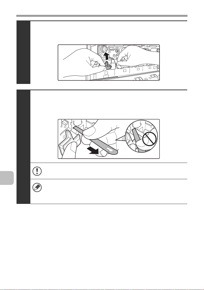
Remove the charger cleaner.
(1) Flip down the charger cleaner lock (A) in the direction of
the arrow, and lift the left end of the charger cleaner.
(1)
4
(A)
(2) Move the charger cleaner to the left and pull it out.
(2)
57
Page 60

REPLACING SUPPLIES AND MAINTENANCE
Clean the main charger.
Holes to be cleaned by the charger cleaner are indicated by labels similar to (A).
(A)
(1) Gently push the charger cleaner all the way in.
(2) Gently pull the charger cleaner out.
5
Position of mark
58
(3) Repeat the above (1) to (2) three times.
• Take care not to let the tip of the charger cleaner become soiled by
toner.
• Clean with the mark ( ) on the charger cleaner facing down.
• Do not use the charger cleaner for any purpose other than cleaning
the main charger.
Page 61

REPLACING SUPPLIES AND MAINTENANCE
Repeat step 5 with each of the other main chargers.
6
Main charger
There are a total of 4 places to be cleaned in the machine as shown.
Replace the charger cleaner in its original position.
Insert the tip of the charger cleaner in toward the right and then press down on
the end of the charger cleaner. The charger cleaner will lock into place.
7
(2)
(1)
Close the main charger cover and rotate the lock
levers in the direction of the arrows to lock the cover.
☞ Replacing the developer cartridge (page 23)
8
59
Page 62

REPLACING SUPPLIES AND MAINTENANCE
Install the toner collection container.
☞ Replacing the toner collection container (page 19)
9
(1)
(2)
Close the front cover.
10
Turn on the power.
Switch the main power switch "ON" and press the [POWER] key ( ) on the
operation panel to turn on the operation panel power.
11
60
Page 63

REPLACING SUPPLIES AND MAINTENANCE
Cleaning and replacing the rollers
To clean the rollers of the paper cassettes, bypass tray, and automatic
document feeder, the rollers must be removed. An old roller should be replaced
as it will cause paper misfeeds and dirty output. The procedures for cleaning
and replacing rollers are explained below.
Warning
Do not use a flammable spray to clean the machine. If gas from the spray
comes in contact with hot electrical components or the fusing unit inside the
machine, fire or electrical shock may result.
• Do not use thinner, benzene, or similar volatile cleaning agents to clean the
machine. These may degrade or discolour the housing.
• It is recommended that you wear thin gloves (that do not interfere with work)
when handling the rollers. If you do not wear gloves, wash your hands well to
remove all oil before handling the rollers.
• When cleaning or replacing rollers, be careful of protruding parts on the
inside of the machine.
Cleaning and replacing paper cassette rollers
If you find that paper from a paper cassette misfeeds or is soiled by the rollers,
remove the rollers and clean them. If misfeeds or soiling continue to occur,
replace the rollers.
Press the [POWER] key ( ) on the operation panel
to turn off the panel power, and then switch the
main power switch to the off position.
1
61
Page 64

REPLACING SUPPLIES AND MAINTENANCE
(2)
After pulling the paper cassette all the way out, lift
the cassette up and out.
2
All cassettes can be removed in a similar way.
Remove three rollers that are at the right back in the cassette.
To remove roller (1), first remove roller (2).
To remove roller (2), grasp the end of the roller with part (A) pulled down and
pull the roller straight out. Do not remove part (B); leave it in position.
(1)
62
3
(B)
(2)
(A)
• Do not insert your hand into any place other than the installation
position of each roller.
• Do not touch the surface of the rollers if your hands are dirty.
Grasp each roller and slowly pull out.
Grasp this part of the roller with your
fingers and pull the roller out.
Page 65

REPLACING SUPPLIES AND MAINTENANCE
To clean the removed rollers, wipe each roller with
a clean cloth.
Caution
When cleaning the rollers, be careful not to injure your hands.
4
Do not touch the surface of the rollers if your hands are dirty.
• When you replace rollers, go to the next step.
• If the dirt is difficult to remove, moisten the cloth with water or a
neutral detergent and then wipe the roller dry with a clean, dry cloth
until no moisture remains.
63
Page 66

REPLACING SUPPLIES AND MAINTENANCE
Install the rollers in their respective positions.
Make sure that the roller numbers match the numbers on the machine in the
illustration below, and install the rollers. Install roller (1) before installing roller (2).
To install roller (2), grasp the end of the roller with part (A) pulled down and
insert the roller.
Make sure the rollers click into place. If a roller does not click into place, rotate
it slightly to find the correct position.
5
(3)
(B)
(1)
(2)
(A)
(1) (2) (3)
\
Front
Rear
• Do not insert your hand into any place other than the installation
position of each roller.
• Do not touch the surface of the rollers if your hands are dirty.
• Do not apply force to (B). This may cause failure.
64
Keep the used rollers in a plastic bag (do not discard it). A plastic bag is
contained in a new roller package.
Page 67

REPLACING SUPPLIES AND MAINTENANCE
Replace the paper cassette.
6
With the far side of the cassette tilted slightly down and the near side
slightly up, place the cassette on the rails, level the cassette, and then
push it in.
Turn on the power.
Switch the main power switch "ON" and press the [POWER] key ( ) on the
operation panel to turn on the operation panel power.
7
After turning on the power, make sure that an error message regarding
replacement of the rollers does not appear.
65
Page 68

REPLACING SUPPLIES AND MAINTENANCE
Cleaning and replacing the bypass tray rollers
If you find that paper fed from the bypass tray misfeeds or is soiled by the roller,
remove and clean the roller. If misfeeds or soiling continue to occur, replace the
roller.
Before starting, remove the paper from the bypass tray.
Press the [POWER] key ( ) on the operation panel
to turn off the panel power, and then switch the
main power switch to the off position.
1
Remove the roller cover from the bypass tray.
Place your fingers behind the marks on the roller cover and pull straight
toward you. Pull alternately on the left and right side of the roller cover.
66
Marks
2
• To obtain sufficient space when removing the roller cover, open the
guides on the bypass tray to their maximum width.
• Do not apply force to (A). This may cause
failure.
Page 69

REPLACING SUPPLIES AND MAINTENANCE
To clean the rollers, wipe each roller with a clean cloth.
3
Caution
When cleaning the rollers, be careful not to injure your hands.
Do not touch the surface of the roller if your hands are dirty.
• When you replace roller, go to the next step.
• If the dirt is difficult to remove, moisten the cloth with a small amount
of water or neutral detergent, and then wipe with a clean, dry cloth
until no moisture remains.
Move the knobs on the left and right sides of the
roller to the specified positions.
4
Move the knobs until they click into place.
67
Page 70

REPLACING SUPPLIES AND MAINTENANCE
Move the fixtures on the left and right sides of the
roller to the positions of the knobs.
5
Move the feed roller to the left and remove it.
Move the roller until it is completely separated from the shaft pin.
6
68
Do not insert your hand into any place other than the location of the
roller.
Remove the pad under the roller.
7
Do not insert your hand into any place other than the installation position
of pad.
Keep the used pad in a plastic bag (do not discard it). A plastic bag is
contained in a new pad package.
Page 71

REPLACING SUPPLIES AND MAINTENANCE
Attach a new pad and install the feed roller.
Align the roller with the shaft pin and attach the roller.
8
• Do not touch the surface of the roller and pad if your hands are dirty.
• Do not insert your hand into any place other than the location of the
roller and pad.
Keep the used roller in a plastic bag (do not discard it). A plastic bag is
contained in a new roller package.
69
Page 72

REPLACING SUPPLIES AND MAINTENANCE
Return the roller fixtures and knobs to their
original positions.
9
Attach the roller cover on the bypass tray.
Press the cover onto the bypass tray so that it locks into place.
70
10
Page 73

REPLACING SUPPLIES AND MAINTENANCE
Turn on the power.
Switch the main power switch "ON" and press the [POWER] key ( ) on the
operation panel to turn on the operation panel power.
11
71
Page 74

REPLACING SUPPLIES AND MAINTENANCE
Cleaning and replacing the automatic document
feeder rollers
If you find that originals fed through the automatic document feeder misfeed or
are soiled by the rollers, remove the rollers and clean them. If misfeeds or
soiling continue to occur, replace the rollers.
Before starting, remove any originals from the automatic document feeder.
Press the [POWER] key ( ) on the operation panel
to turn off the panel power, and then switch the
main power switch to the off position.
1
72
Open the document conveyor cover on the
automatic document feeder.
2
Page 75

REPLACING SUPPLIES AND MAINTENANCE
Lift up the knob that holds the roller shaft.
3
Remove the roller with the shaft.
(1) Pull down the release lever.
(2) Remove the shaft rotating the roller cover upward and
4
remove the shaft.
(3)
(2)
If the roller cover is not pointing straight up when the shaft is removed, a
failure may occur.
(1)
73
Page 76

REPLACING SUPPLIES AND MAINTENANCE
To clean the removed rollers, wipe each roller with
a clean cloth.
Rotate the shaft as you wipe so that the entire roller is wiped.
5
Caution
When cleaning the rollers, be careful not to injure your hands.
• Do not touch the surface of the roller if your hands are dirty.
• The shaft can only be rotated in one direction. Do not force the shaft
to rotate.
• If the dirt is difficult to remove, moisten the cloth with water or a
neutral detergent and then wipe the roller dry with a clean, dry cloth
until no moisture remains and go to the step 10.
• When you replace roller, go to the next step.
74
Release the left or right hooks that hold the pad
and remove the pad.
6
• When the hooks are released, the pad will spring up. Lift the pad up
from that position to remove it.
• Keep the used pad in a plastic bag (do not discard it). A plastic bag is
contained in a new roller package.
Page 77

REPLACING SUPPLIES AND MAINTENANCE
Attach the pad.
(1) Align the protrusion on the pad with the spring on the
automatic document feeder.
(2) Push the pad into the automatic document feeder.
7
The hooks lock onto the pad and secure it.
Do not touch the surface of the pad if your hands are dirty.
75
Page 78

REPLACING SUPPLIES AND MAINTENANCE
With the roller cover pointing up, insert the shaft
into the hole in the automatic document feeder,
and rotate the shaft to return the roller to its
original position.
If the shaft does not fit into place, rotate it slightly to find the correct position.
(1)
(2)
8
Caution
When cleaning the rollers, be careful not to injure your hands.
When cleaning or replacing roller, make sure your hands are clean
before touching the surface of the roller.
Lower the knob that secures the roller.
9
(3)
(A)
76
Page 79

REPLACING SUPPLIES AND MAINTENANCE
Close the document conveyor cover on the
automatic document feeder.
10
• When cleaning or replacing roller, make sure your hands are clean
before touching the surface of the roller.
• Take care that your fingers are not pinched when closing the cover.
Turn on the power.
Switch the main power switch "ON" and press the [POWER] key ( ) on the
operation panel to turn on the operation panel power.
11
77
Page 80

REPLACING SUPPLIES AND MAINTENANCE
Cleaning the laser unit
When the laser unit inside the machine becomes dirty, line patterns (coloured
lines) may form in the printed image. Follow the steps below to clean the laser
unit.
Identifying lines (coloured lines) caused by a dirty laser unit
• Coloured lines always appear in the same place. (The lines are never black.)
• The coloured lines are parallel to the direction of paper feeding.
Direction of
paper feeding
Coloured line
• Coloured lines appear not only on copies but also on print jobs from a
computer. (The same lines appear on both copies and print jobs.)
Press the [POWER] key ( ) on the operation panel
to turn off the panel power, and then switch the
main power switch to the off position.
78
1
Page 81

REPLACING SUPPLIES AND MAINTENANCE
Open the front cover and remove the toner
collection container.
☞ Replacing the toner collection container (page 19)
2
Do not point the holes down as used toner will spill out.
Remove the cleaning tool for the writing unit from
the front cover.
3
79
Page 82

REPLACING SUPPLIES AND MAINTENANCE
Make sure that the cleaner at the tip of the cleaning
tool is not dirty.
4
If the cleaner is dirty, remove the cleaner and replace it with a clean
one. For the procedure for replacing the cleaner, see steps 5 through 7.
If the cleaner is not dirty, go to step 8.
Cleaner
Pull out the replacement cleaner from the toner
collection container.
5
80
Page 83

REPLACING SUPPLIES AND MAINTENANCE
Remove the dirty cleaner.
Firmly grasp the tool close to where the cleaner is attached.
Use your other hand to press down on the hook that secures the cleaner and
remove the cleaner.
6
Return the removed cleaner to the toner collection container.
Attach the new cleaner to the cleaning tool.
Firmly grasp the tool close to where the cleaner is attached.
Use your other hand to press down on the hook that secures the cleaner and
remove the cleaner.
7
Make sure that the cleaner is firmly attached to the cleaning tool.
81
Page 84

REPLACING SUPPLIES AND MAINTENANCE
Clean the laser unit.
(1) Point the cleaner down and slowly insert the tool into
the hole that you wish to clean.
The parts of the writing unit that require cleaning are indicated by labels
similar to (A).
(2) Insert the cleaning tool all the way into the hole and
then pull it back out.
8
Pull the cleaning tool out until you feel the tip of the tool leave the
cleaning surface of the laser unit.
(A)
82
(3) Repeat step (2) two or three times and then remove the
cleaning tool.
Page 85

REPLACING SUPPLIES AND MAINTENANCE
Repeat step 8 to clean all holes in the laser unit.
9
Holes to be cleaned
There are a total of 4 holes to be cleaned in the laser unit.
If the cleaner becomes dirty during cleaning, replace with a new
cleaner. For the procedure for replacing the cleaner, see steps 5 to 7.
Replace the cleaning tool.
10
Install the toner collection container.
☞ Replacing the toner collection container (page 19)
11
(1)
(2)
83
Page 86

REPLACING SUPPLIES AND MAINTENANCE
Close the front cover.
12
Take care that your fingers are not pinched when closing the cover.
Turn on the power.
Switch the main power switch "ON" and press the [POWER] key ( ) on the
operation panel to turn on the operation panel power.
13
84
Page 87

REPLACING SUPPLIES AND MAINTENANCE
Cleaning the PT charger of the primary transfer belt unit
If black or coloured lines still remain after the document glass / automatic
document feeder and main charger have been cleaned, use the PT charger
cleaner to clean the PT charger.
Press the [POWER] key ( ) on the operation panel
to turn off the panel power, and then switch the
main power switch to the off position.
1
Open the front cover and remove the toner
collection container.
☞ Replacing the toner collection container (page 19)
2
Do not point the holes down as used toner will spill out.
85
Page 88

REPLACING SUPPLIES AND MAINTENANCE
Clean the PT charger.
(1) Slowly pull the PT charger cleaner out until you feel a
slight resistance.
3
(2) Slowly push the PT charger cleaner back in.
(3) Repeat the above (1) to (2) three times.
86
Install the toner collection container.
☞ Replacing the toner collection container (page 19)
4
(1)
(2)
Page 89

REPLACING SUPPLIES AND MAINTENANCE
Close the front cover.
5
Take care that your fingers are not pinched when closing the cover.
Turn on the power.
Switch the main power switch "ON" and press the [POWER] key ( ) on the
operation panel to turn on the operation panel power.
6
87
Page 90

REPLACING SUPPLIES AND MAINTENANCE
Executing the fusing cleaning mode
If the printed image is dirty as shown in the following illustration, the fusing unit
may be dirty.
• The dirt will appear at fixed intervals.
• The dirt will appear horizontally (perpendicular to the direction of feeding of
the paper).
Direction of
paper feeding
Dirt
Press the [SYSTEM SETTINGS] key on the
1
operation panel.
Select the [Device Control] key.
2
88
Select the [Other Setting] key.
3
Select the [Execute] key of the "Fusing Cleaning
4
Mode".
Page 91

TROUBLESHOOTING
This section explains what to do when an error code* appears in the display.
* An error code is a code that appears when a problem has occurred in the machine.
Error code
Alphabet
Numbers
Code:xx-xx.
Please refer to operation manual.
When an error code appears
Check if the displayed error code is in the table below. "xx" in the table
represents two numeric digits.
Error codes
F3-xx H4-xx U1-xx PF-xx
H3-xx H5-xx U2-xx
If the displayed error code is in the table, write down the error code and contact
your dealer or nearest authorised service representative.
If an error code that is not in the above table appears, turn the machine power
off and then on.
To turn on the power again, follow the procedure below.
When the power is turned off, data that was being processed may be lost.
Press the [POWER] key ( ) on the operation panel.
1
89
Page 92

TROUBLESHOOTING
Switch the main power switch to the off position.
2
Wait until the main power indicator turns off and
then switch on the main power switch.
3
Press the [POWER] key ( ) on the operation panel.
4
If the error code still appears after the power is turned on, write down the error
code and contact your dealer or nearest authorised service representative.
90
Page 93

TROUBLESHOOTING
Checking the status of the machine
The procedure for printing machine information is explained below.
Printing the machine information list
Press the [SYSTEM SETTINGS] key on the
1
operation panel.
Select the [List Print (User)] key.
2
Select the [Print] key of the "Machine Information
3
List".
Printing the image quality check chart
Press the [SYSTEM SETTINGS] key on the
1
operation panel.
Select the [List Print (User)] key.
2
Select the [Print] key of the "Image Quality Check
3
Chart".
91
Page 94

SPECIFICATIONS
Machine specifications / copier specifications
Name
Type
Display
Photoconductive type
Printing method
Developer system
Fusing system
Scanning resolution
Printing resolution
Scanning gradation
Printing gradation
Original sizes / types
Copy sizes
Print margins
Digital Full Colour Multifunctional System
DX-C310/DX-C311/DX-C380/DX-C381
Desktop
DX-C310/DX-C380 : 4.3 inch colour LCD
DX-C311/DX-C381 : 8.5 inch colour touch panel LCD
OPC drum
Electrophotographic system (laser)
Dry-type two-component magnetic brush development
Heat rollers
Black and white scanning: 600 x 300 dpi ,
600 x 600 dpi
(factory default
Document
glass
Reversing
single pass
feeder
(automatic
document
feeder)
600 x 600 dpi
256 levels
Equivalent to 256 levels
Max. A4 (8-1/2" x 11") / sheets, bound documents
Maximum: A4 (8-1/2" x 11") Minimum: A5
(5-1/4" x 5-3/4")
Leading edge / trailing edge: total 8 mm (21/64") or less,
near edge / far edge: total 8 mm (21/64") or less
Colour scanning: 600 x 300 dpi,
Black and white scanning: 600 x 300 dpi
Colour scanning: 600 x 300 dpi
values)
600 x 600 dpi
(factory default
values)
(factory default
values),
600 x 600 dpi
(factory default
values),
600 x 600 dpi
92
Page 95

SPECIFICATIONS
Machine specifications / copier specifications
(Continued)
Warm-up time
First-copy time*
Copy ratios
Continuous copy
Automatic document
90 seconds or less (at room temperature of 23°C
(73.4°F) and rated voltage)
Colour copy time:8.9 seconds or less
Black and white copy time: 8.0 seconds or less
(Portrait feeding of A4 (8-1/2" x 11") sheets from 1st
paper tray, without auto colour selection and auto colour
mode.)
Variable: 50% to 200% in increments of 1%, total 151
increments
Fixed presets:
Two reduction ratios and two enlargement ratios can be
stored.
999 copies
See "Automatic document feeder specifications".
50%, 70%, 81%, 86%, 100%, 115%,
122%, 141% and 200% for AB sizes
50%, 64%, 77%, 100%, 121%, 129%
and 200% for inch sizes
.
feeder
Paper sizes: A4, B5, A5, 8-1/2" x 14",
8-1/2" x 13-1/2", 8-1/2" x 13-2/5",
8-1/2" x 13", 8-1/2" x 11",
7-1/4" x 10-1/2", 5-1/2" x 8-1/2", 16K
Tray 1
* First copy out time is measured with original on the document glass in full ready
condition with fuser at operating temperature and mirror motor at operating speed in
each of black and white mode and colour mode, actual time may vary based on
environment conditions.
Paper weight: Plain paper (60 g/m
(16 lbs. to 28 lbs.))
Paper capacity: Plain paper (80 g/m
sheets
Paper types: SHARP-recommended plain paper,
recycled paper and coloured paper
2
to 105 g/m2
2
(21 lbs.)) 500
;
93
Page 96

SPECIFICATIONS
Machine specifications / copier specifications
(Continued)
Paper sizes: A4, B5, A5, 8-1/2" x 14", 8-1/2" x 13-1/2",
8-1/2" x 13-2/5", 8-1/2" x 13", 8-1/2" x 11",
7-1/4" x 10-1/2", 5-1/2" x 8-1/2",
envelopes, 16K (Includes automatic paper
size detection function. Paper sizes from
100 mm x 148 mm (3-15/16" x 5-53/64") to
216 mm x 356 mm (8-33/64" x 14-1/64")
can be entered.)
Bypass tray
Duplex module
Output tray (Centre tray)
Paper weights:
Thin paper (55 g/m2 to 59 g/m2 (15 lbs. to 16 lbs.)), plain
paper (60 g/m
paper (106 g/m2 to 209 g/m2 (28 lbs. bond to 110 lbs.
index))
Paper capacity: Standard paper 100 sheets
Paper types:
SHARP-recommended plain paper, recycled paper,
coloured paper, heavy paper, thin paper, transparency
film, and envelopes (Monarch, Com-10, DL, C5)
Paper sizes: A4, B5, A5, 8-1/2" x 14",
Paper weight: Plain paper (60 g/m2 to 105 g/m2 (16 lbs.
Paper types:SHARP-recommended plain paper,
Output method: Face-down output
Output capacity: 250 sheets (using SHARP-recommended
(The maximum number of sheets that can be held varies
depending on ambient conditions in the installation
location, the type of paper, and the storage conditions of
the paper.)
Tray full sensor: Yes
2
to 105 g/m2 (16 lbs. to 28 lbs.)), heavy
8-1/2" x 13-1/2",
8-1/2" x 13-2/5",
5-1/2" x 8-1/2", 16K
to 28 lbs.))
recycled paper, and coloured paper
A4 or 8-1/2" x 11" paper)
8-1/2" x 13", 8-1/2" x 11",
94
Page 97

SPECIFICATIONS
Machine specifications / copier specifications
(Continued)
LAN connectivity:
10Base-T / 10 0Base-TX / 1000Base-T
USB connectivity:
Interface port
Required power supply
Power consumption
Dimensions
Weight
Overall dimensions
* Type A connectors are located on the front and back right of the machine (two
connectors); however, the connectors cannot be used simultaneously. The connector
on the back of the machine is not initially available for use. If you wish to use the
connector, contact your dealer or nearest authorised service representative.
Type A connector supports USB 2.0 (Hi speed)*
Compatibility requirements of USB 2.0
Memory Capacity:Max. 32 GB
Disk Format: FAT32 only
Type B connector supports USB 2.0 (Hi speed)
Local voltage ±10%
(For the power supply req uirements, see the nam e plate
in the lower corner of the left side of the machine.)
1.84 kW (220-240 V) / 1.44 kW (100-127 V)
DX-C310/DX-C380:
560 mm (W) x
22-3/64" (W) x 17-1/4" (D) x 28-7/64" (H)
(
DX-C311/DX-C381:
560 mm (W) x 493 mm (D) x 714 mm (H)
(22-3/64" (W) x 19-13/32" (D) x 28-7/64" (H))
Approx. 46 kg (101.4 lbs.)
DX-C310/DX-C380:
868 mm (W) x 438 mm (D) (34-11/64" (W) x 17-1/4" (D))
(when bypass tray is extended)
DX-C311/DX-C381:
868 mm (W) x 493 mm (D) (34-11/64" (W) x 19-13/32" (D))
(when bypass tray is extended)
438
mm (D) x 714 mm (H)
)
95
Page 98

SPECIFICATIONS
Continuous copying speeds*
Model
Copy ratio
Copy mode
A4,
B5, 16K
8-1/2" x 11", 7-1/4" x 10-1/2"
* Copy speed during output of the second copy and following copies when performing
continuous one-sided copying of the same page (excluding offset output) using plain
one-sided paper from a tray other than the bypass tray.
DX-C310/DX-C311 DX-C380/DX-C381
100% / Reduced / Enlarged
Colour B/W Colour B/W
31
copies/min.
31
copies/min.
31
copies/min.
31
copies/min.
38
copies/min.
40
copies/min.
copies/min.
copies/min.
38
40
Ambient environment
(Humidity)
85%
60%
20%
10˚C
(54˚F)
30˚C
35˚C (Temperature)
(86˚F)
(91˚F)
96
Page 99

SPECIFICATIONS
Acoustic noise emission (measurement according to
ISO7779)
Model
Sound power level LwA
Printing mode
(continuous printing)
Standby mode
Sound pressure level LpA (actual measurement)
Bystander
Printing
mode
positions
Operator
positions
Bystander
Standby
mode
positions
Operator
positions
DX-C310/DX-C311 DX-C380/DX-C381
Colour: 6.9 B
B/W: 6.9 B
5.3B 5.3B
Colour: 53 dB (A)
B/W: 53 dB (A)
Colour: 54 dB (A)
B/W: 53 dB (A)
37 dB (A) 38 dB (A)
37 dB (A) 38 dB (A)
Colour: 7.0 B
B/W: 7.1 B
Colour: 55 dB (A)
B/W: 55 dB (A)
Colour: 57 dB (A)
B/W: 57 dB (A)
Automatic document feeder specifications
A4 to A5, 8-1/2" x 14" to 5-1/2" x 8-1/2", long paper
Original sizes
(max. width 216 mm (8-1/2") x max. length 500 mm* (19-5/8"),
scanning in mono 2 mode of one side only is possible in fax and
image scan modes)
One-sided 35g/m2 to 128g/m2 (9 lbs. to 32 lbs.) (Paper weights
g
Original weight
Capacity
* Scanning in mono 2 mode of one side only is possible in fax and scan send modes.
from 35
scan mode.)
Two-sided 50
50 sheets (80 g/m2 (21 lbs.)) Maximum stack height of 6.5 mm
(1/4")
/m2 (9 lbs.) to 49g/m2 (13 lbs.) require the use of slow
g
/m2 to 105g/m2 (13 lbs. to 28 lbs.)
97
Page 100

SPECIFICATIONS
Business card feeder specifications
Model
Sizes
Business card*
Thickness
Scanning
Capacity
Dimensions
Weight
* Device may be unable to correctly feed and scan the business card depending on the
business card's condition, material, form, and fabrication method.
MX-BTX1
51 mm x 89 mm to 55 mm x 91 mm
(2-1/64" x 3-33/64" to 2-11/64" x 3-19/32")
0.1 mm to 0.2 mm (0.004" to 0.008")
Single-s ided (face-up)
Stack height 3.5 mm (9/64") maximum
115 mm (W) x 88 mm (D) x 25 mm (H)
(4-17/32" (W) x 3-15/32" (D) x 63/64" (H))
Approx. 40 g (0.09 lbs.)
500-sheet paper feed unit specifications
Model
Paper sizes
Paper weight
Paper capacity
MX-CSX1 (tray 2) MX-CSX2 (tray 3, tray 4)
A4, B5, A5*, 8-1/2" x 14", 8-1/2" x 13-1/2", 8-1/2" x 13-2/5",
8-1/2" x 13", 8-1/2" x 11", 7-1/4" x 10-1/2", 5-1/2" x 8-1/2"*, 16K
Plain paper (60 g/m2 to 105 g/m2 (16 lbs. to 28 lbs.))
500 sheets (80 g/m2 (21 lbs.)) x 1 tray
Paper types
Automatic paper
size detection
Power supply
Dimensions
Weight
* Only MX-CSX1 can be used.
SHARP-recommended plain pape r, recy cled p aper, a nd c oloure d
paper
When "Auto-AB" detection is selected:
A4, B5, A5*, 216 mm x 330 mm (8-1/2" x 13")
When "Auto-Inch" detection is selected:
8-1/2" x 14", 8-1/2" x 11", 7-1/4" x 10-1/2", 5-1/2" x 8-1/2"*
Supplied from the machine
535 mm (W) x 438 mm (D) x 112 mm (H)
(21-1/16" (W) x 17-1/4" (D) x 4-13/32" (H))
(not including adjuster)
Approx. 6.8 kg (15.0 lbs.) Approx. 5.6 kg (12.3 lbs.)
98
535 mm (W) x 438 mm (D) x 110 mm (H)
(21-1/16" (W) x17-1/4" (D) x 4-21/64" (H))
(not including adjuster)
 Loading...