

Page 1

MODEL:
DIGITAL FULL COLOUR MULTIFUNCTIONAL SYSTEM
Installation GuideInstallation GuideInstallation Guide
PART 1
HARDWARE INSTALLATION
PART 2
SOFTWARE INSTALLATION
DX-C310
DX-C311
DX-C380
DX-C381
Keep this manual close at hand for reference
whenever needed.
Page 2
Thank you for purchasing this product. This manual explains how to set up your
machine so that it is ready for use, including the procedures for installation of
the machine, options, and software.
INSTALLATION PROCEDURE
To ensure safe use of the machine, read the Maintenance &
Safety Guide.
The Maintenance & Safety Guide contains safety information and
guidelines for the installation site.
If you are using the machine for the first time, be sure to read
Part 1, "HARDWARE INSTALLATION" (page 1), and install the
machine correctly.
After installing the machine, if you will be using the printer
function or the scanner function, install the necessary software
as explained in Part 2, "SOFTWARE INSTALLATION" (page 41).
To gain a general understanding of how to use the machine,
read the Quick Start Guide.
The Quick Start Guide explains the basic procedures for operating
the machine.
Illustrations and the operation panel shown in this manual
The peripheral devices are generally optional, however, some models include certain
peripheral devices as standard equipment.
The explanations in this manual assume that 500-sheet paper feed units (total of four
trays) are installed on the DX-C381.
For some functions and procedures, the explanations assume that devices other than
the above are installed.
Page 3

PART 1
HARDWARE INSTALLATION
PART 1
HARDWARE INSTALLATION
UNPACKING
INSTALLING OPTIONAL
EQUIPMENT
INSTALLING THE
ACCESSORIES
TURNING ON THE POWER AND
ADJUSTING THE IMAGE QUALITY
1
Page 4

TABLE OF CONTENTS
UNPACKING
1
SETUP PROCEDURE. . . . . . . . . . . . . . . . . . . . . . . . . . . . . . . . . . . . . . . . . . . . . . . . . . . 3
CHECKING PACKED COMPONENTS AND ACCESSORIES. . . . . . . . . . . . . . . . . . . . 4
REMOVE THE PROTECTIVE MATERIALS . . . . . . . . . . . . . . . . . . . . . . . . . . . . . . . . . . 6
INSTALLING OPTIONAL EQUIPMENT
2
INSTALLING THE 500-SHEET PAPER FEED UNIT . . . . . . . . . . . . . . . . . . . . . . . . . . . 8
• INSTALL THE MX-CSX1 OR THE MX-CSX2 TO THE MX-CSX2 . . . . . . . . . . . . . 10
• INSTALL THE MAIN UNIT TO THE MX-CSX1 . . . . . . . . . . . . . . . . . . . . . . . . . . . 14
INSTALLING THE FINISHER . . . . . . . . . . . . . . . . . . . . . . . . . . . . . . . . . . . . . . . . . . . . 17
INSTALLING THE ACCESSORIES
3
INSTALLING THE DEVELOPER CARTRIDGE . . . . . . . . . . . . . . . . . . . . . . . . . . . . . . 23
INSTALLING THE OPERATION MANUAL POCKET . . . . . . . . . . . . . . . . . . . . . . . . . 32
LOADING PAPER. . . . . . . . . . . . . . . . . . . . . . . . . . . . . . . . . . . . . . . . . . . . . . . . . . . . . 33
TURNING ON THE POWER AND ADJUSTING THE IMAGE QUALITY
4
POWER-ON AND AUTO ADJUSTMENT OF THE DEVELOPER . . . . . . . . . . . . . . . . 36
INSTALLING THE TONER CARTRIDGE. . . . . . . . . . . . . . . . . . . . . . . . . . . . . . . . . . . 37
TURNING OFF THE POWER OF THE MACHINE . . . . . . . . . . . . . . . . . . . . . . . . . . . . 40
2
Page 5
1
This section gives an overview of the setup procedures and explains
preparations for setup such as removing the packaging.
UNPACKING
SETUP PROCEDURE
When using the machine for the first time, setup the machine following the
procedure shown below.
Be sure to set up the machine in the order shown below.
If you do not follow this order, the machine may not operate correctly and a
failure may result.
UNPACKING
•
Open the carton, and make sure that all the accessories are supplied with the machine.
• Remove the protective materials.
INSTALLING OPTIONAL EQUIPMENT (page 8)
If you did not purchase this option, go to the next step.
•
Install the 500-sheet paper feed unit. (Only if you purchased a 500-sheet paper feed unit.)
• Install the finisher. (Only if you purchased a finisher.)
INSTALLING THE ACCESSORIES (page 23)
• Install the developer cartridge.
• Install the operation manual pocket.
• Load the paper in the paper tray.
TURNING ON THE POWER AND ADJUSTING THE IMAGE QUALITY (page 36)
• Plug the other end of the power cord into the nearest outlet and turn on the power.
• Install the toner cartridge.
3
Page 6
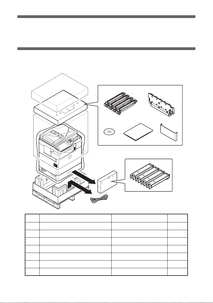
CHECKING PACKED COMPONENTS
AND ACCESSORIES
Open the carton and check if the following components and accessories are
included.
12
34 5
6
7
No. Packed part names
1 Developer cartridge 1 piece for each colour
2 Toner collection container 1
3 Software CD-ROM 1
4 Operation manual 1 set
5 Operation manual pocket 1
6 Toner cartridge 1 piece for each colour
7 Power cord 1
Quantity
4
Check
Page 7
CHECKING PACKED COMPONENTS AND ACCESSORIES
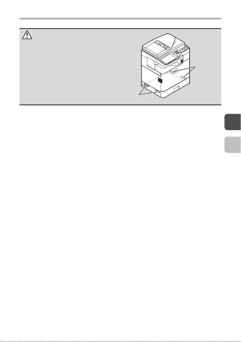
Caution
The main unit is extremely heavy, and
thus two people are required to do the
work. When lifting the main unit, grasp
the handles on each side firmly.
Handles
Handles
5
Page 8
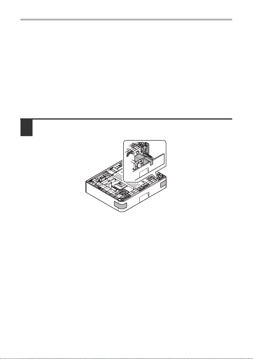
REMOVE THE PROTECTIVE MATERIALS
Remove all pieces of tape shown in the illustration below.
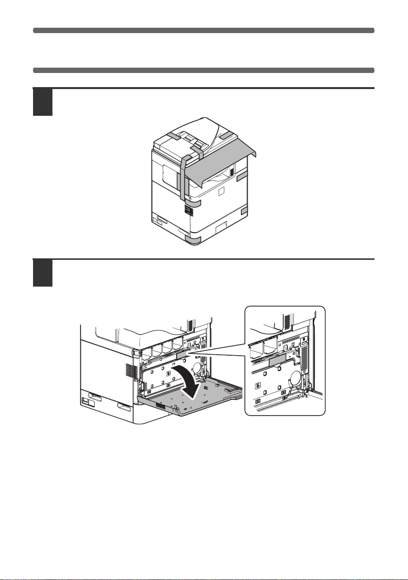
1
Open the front cover and remove the fixing tape in the illustration
2
below.
After removing the fixing tape, close the front cover.
6
Page 9
REMOVE THE PROTECTIVE MATERIALS
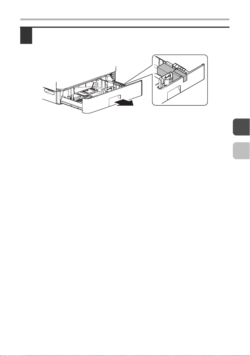
Gently pull the tray out until it stops and remove the fixing tape and
3
protective material.
After removing the fixing tape and protective material, insert the tray slowly.
• If you purchased an optional paper feed unit or finisher:
☞ INSTALLING OPTIONAL EQUIPMENT (page 8)
• If you did not purchase any of the above options:
☞ INSTALLING THE ACCESSORIES (page 23)
7
Page 10
INSTALLING OPTIONAL
2
This section explains how to install the optional paper feed units and finisher. If
you purchased both a paper feed unit and a finisher, be sure to install the paper
feed unit first.
• If you only purchased a finisher:
• If you did not purchase any of the above options:
EQUIPMENT
☞ INSTALLING THE FINISHER (page 17)
☞ INSTALLING THE ACCESSORIES (page 23)
If you are already using the machine and have newly purchased an option,
make sure that the LINE indicator and the DATA indicator on the operation
panel are off, turn off the power, and remove the power plug from the outlet
before starting installation work.
☞ TURNING OFF THE POWER OF THE MACHINE (page 40)
INSTALLING THE 500-SHEET
PAPER FEED UNIT
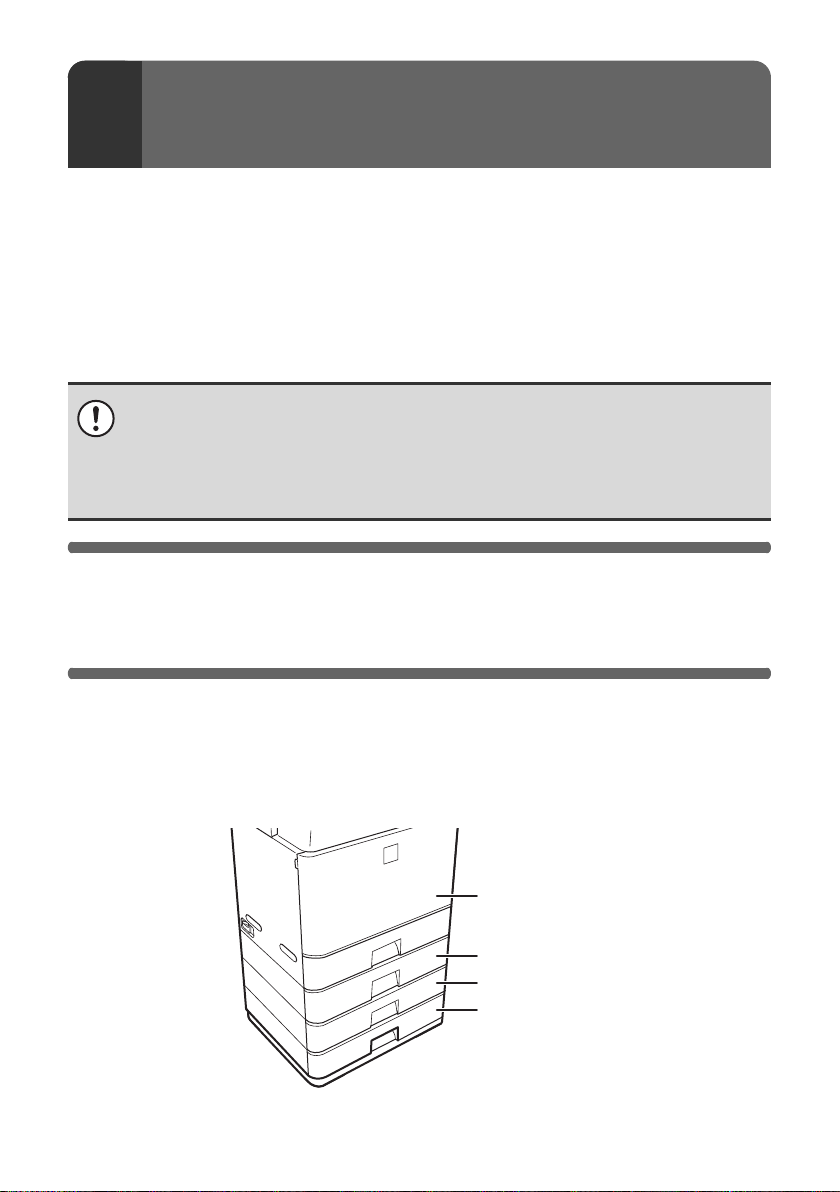
If you purchased a 500-sheet paper feed unit, follow the steps below to install
the unit on the main unit.
If you are installing multiple 500-sheet paper feed units, attach MX-CSX1 and
MX-CSX2 units together before installing the units on the main unit. The order of
unit installation should always be main unit, MX-CSX1, MX-CSX2.
Main unit
MX-CSX1
MX-CSX2
MX-CSX2
8
Page 11
INSTALLING THE 500-SHEET PAPER FEED UNIT
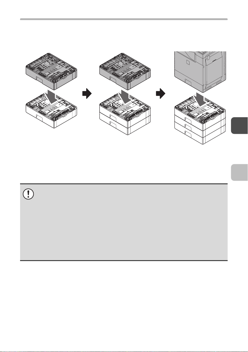
X Installing multiple paper feed units
(1) MX-CSX2 + MX-CSX2
☞ INSTALL THE MX-CSX1 OR THE MX-CSX2 TO
THE MX-CSX2 (page 10)
• Only the MX-CSX1 can be installed directly under the main unit. Take care
that you perform the installation steps in the correct order.
The paper trays of the main unit, MX-CSX1, and MX-CSX2 are not
interchangeable. If a tray is installed in the wrong location, it will not be
possible to correctly close the tray. After removing a tray from a unit, be sure
to replace the tray in its correction location.
• When two or more optional paper feed units are installed, there is a danger
that the machine will topple.
When installing two or more paper feed units, be sure to install the specified
cabinet to prevent toppling before using the machine.
(2) MX-CSX1 + (1) (3) Main unit + (2)
☞ INSTALL THE MAIN
UNIT TO THE
MX-CSX1 (page 14)
9
Page 12
INSTALLING THE 500-SHEET PAPER FEED UNIT
INSTALL THE MX-CSX1 OR THE MX-CSX2
TO THE MX-CSX2
In the example below, installation of the MX-CSX1 to the MX-CSX2 is described.
Installation of the MX-CSX2 to another MX-CSX2 is performed similarly.
If you are installing one MX-CSX1 unit and two MX-CSX2 units (three units
altogether) on the machine, first attach the MX-CSX2 units together as explained
below, and then repeat the procedure to attach the MX-CSX1 unit to the
MX-CSX2 units.
If you only purchased the MX-CSX1:
☞ INSTALL THE MAIN UNIT TO THE MX-CSX1 (page 14)
Remove the 500-sheet paper feed unit from the polyethylene bag, and
1
remove the fixing tape and the protective material.
10
Page 13
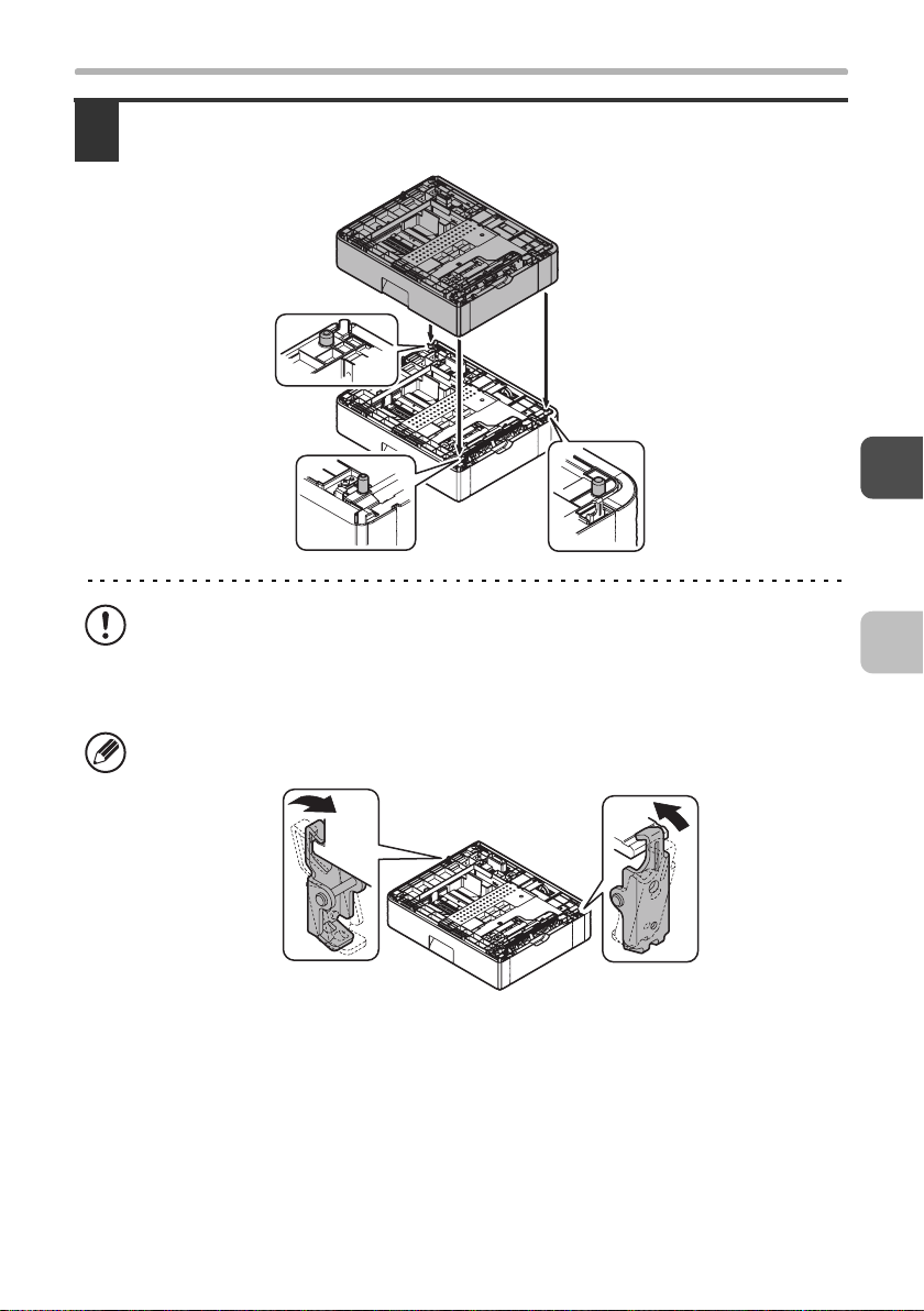
INSTALLING THE 500-SHEET PAPER FEED UNIT
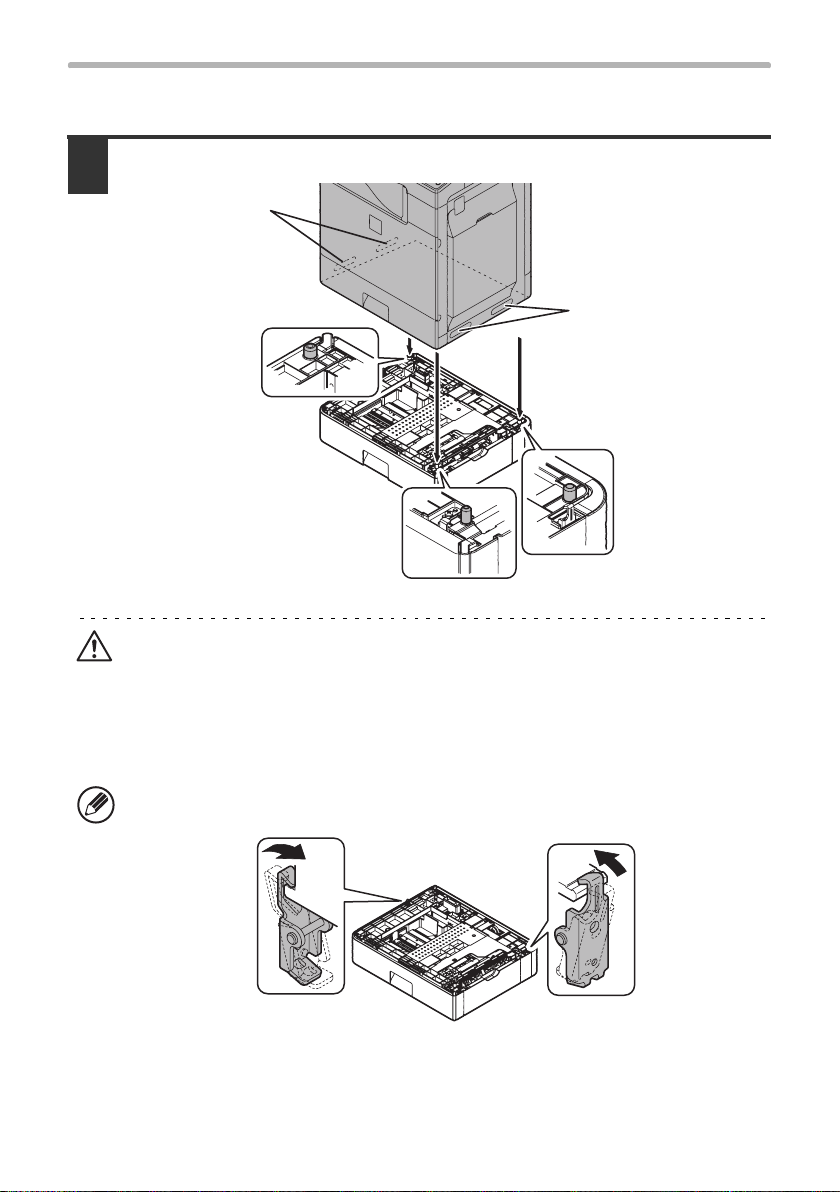
Put the MX-CSX1 (or MX-CSX2) on the MX-CSX2 so that they fit
2
together.
• The left cover is a sliding cover. When lifting the unit, take care that it does not
slide.
• When installing a unit, take care that your fingers do not become pinched
between units.
When the MX-CSX1(or the upper MX-CSX2) is put on the MX-CSX2, it is
automatically locked at the left and the right of the rear side.
11
Page 14
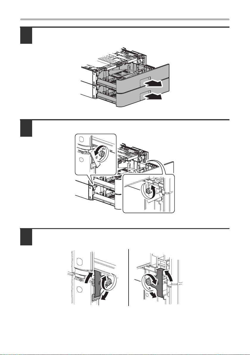
INSTALLING THE 500-SHEET PAPER FEED UNIT
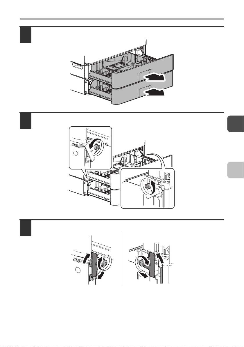
Pull out the trays of the MX-CSX1 (or the upper MX-CSX2) and the
3
MX-CSX2.
Loosen the hand screws on the left and the right sides.
4
Hang the fixing clasp on the MX-CSX1 (or the upper MX-CSX2), and
5
tighten the hand screws.
12
Page 15
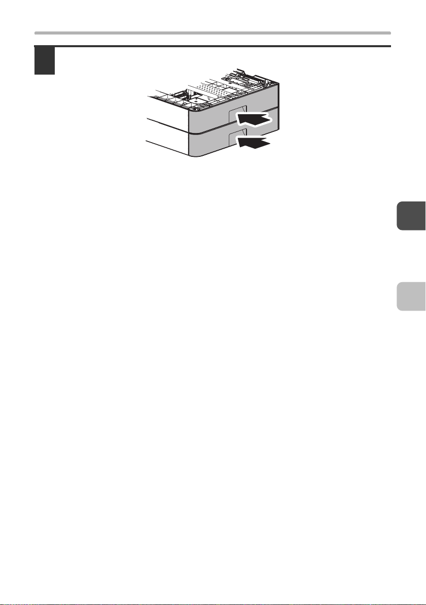
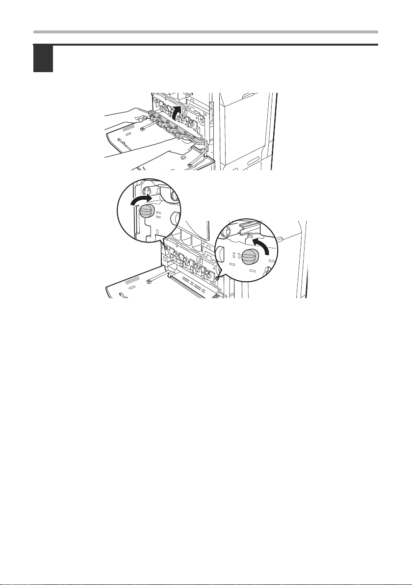
Push in and close the trays.
6
INSTALLING THE 500-SHEET PAPER FEED UNIT
13
Page 16
INSTALLING THE 500-SHEET PAPER FEED UNIT
INSTALL THE MAIN UNIT TO THE MX-CSX1
Put the main unit on the MX-CSX1 so that they fit together.
1
Handles
Handles
Caution
• The main unit is extremely heavy, and thus two people are required to do the
work. When lifting the main unit, grasp the handles on each side firmly.
• When installing a unit, take care that your fingers do not become pinched
between units.
When the main unit is put on the MX-CSX1, it is automatically locked at the left
and the right of the rear side.
14
Page 17
INSTALLING THE 500-SHEET PAPER FEED UNIT
Pull out the tray of the main unit and that of the MX-CSX1.
2
Loosen the hand screws on the left and the right sides.
3
Hang the fixing clasp on the main unit, and tighten the hand screws.
4
15
Page 18

INSTALLING THE 500-SHEET PAPER FEED UNIT
Push in and close the trays.
5
This completes the installation of the 500-sheet paper units.
• If you purchased a finisher:
☞ INSTALLING THE FINISHER (page 17)
• If you did not purchase any of the above options:
☞ INSTALLING THE ACCESSORIES (page 23)
16
Page 19
INSTALLING THE FINISHER
If you purchased a finisher, follow the steps below to install the finisher on the machine.
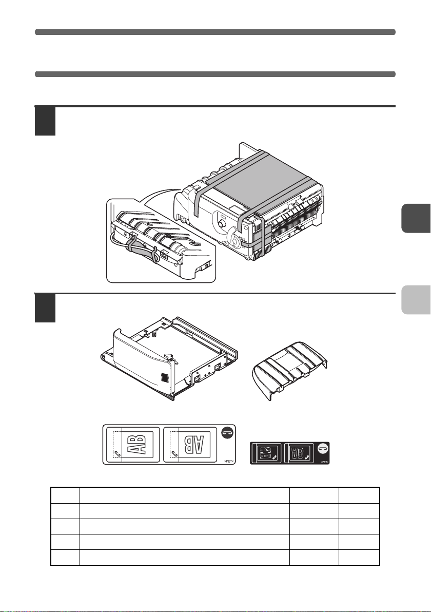
Remove the finisher from the polyethylene bag, and remove the fixing
1
tape and the protective materials.
Check the packed items.
2
21
43
No. Packed part names
1 Machine connection unit 1
2 Paper exit tray 1
3
Staple position label (For automatic document feeder)
4 Staple position label (For document glass) 1
Quantity
Check
1
17
Page 20
INSTALLING THE FINISHER
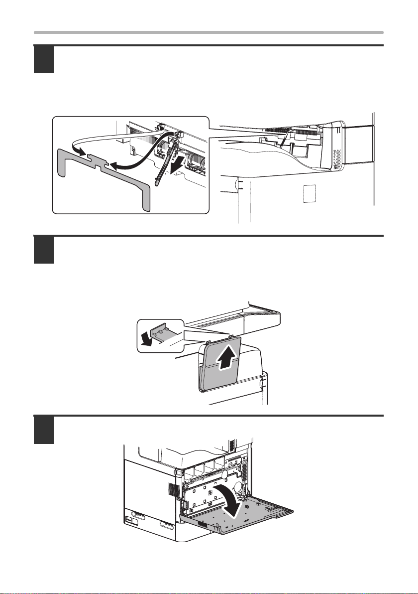
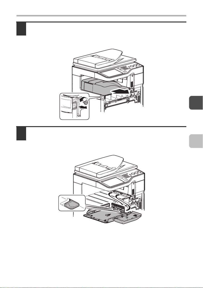
Remove the full detection actuator and the paper exit auxiliary plate at
3
the paper exit port of the main unit.
• Pull the full detection actuator straight out.
• The removed full detection actuator and paper exit auxiliary plate are not used.
Store the removed parts in a safe location where they will not be lost.
Remove the paper exit cover from the right side of the main unit.
4
• While pressing the top of the paper exit cover down, pull it toward you, release
the catches, and pull it out.
• The removed paper exit cover is not used. Store the removed part in a safe
location where it will not be lost.
Open the front cover.
5
18
(1)
(2)
Page 21
INSTALLING THE FINISHER
Remove the coin screw, and remove the paper exit tray.
6
• Pull the paper exit tray out horizontally.
• The removed paper exit tray and coin screw are not used. Store the removed
parts in a safe location where they will not be lost.
Install the machine connection unit (included in the package) to the
7
machine.
Attach the machine connection unit so that the catches (two) on the main unit insert
into the slots on the machine connection unit.
19
Page 22
INSTALLING THE FINISHER
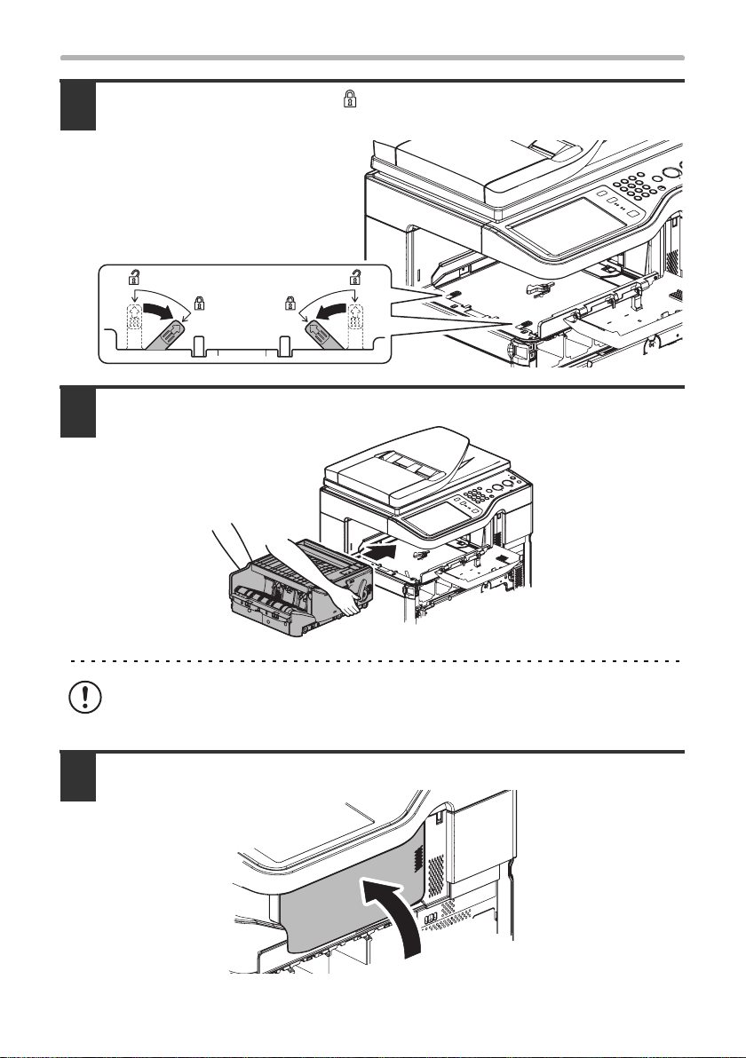
Slide the lock lever toward " " (Lock) to lock the machine
8
connection unit onto the main unit.
Install the finisher to the machine connection unit.
9
The finisher is heavy. When lifting the finisher, firmly grip the front frame and the
back frame.
Close the front cover of the finisher.
10
20
Page 23
INSTALLING THE FINISHER
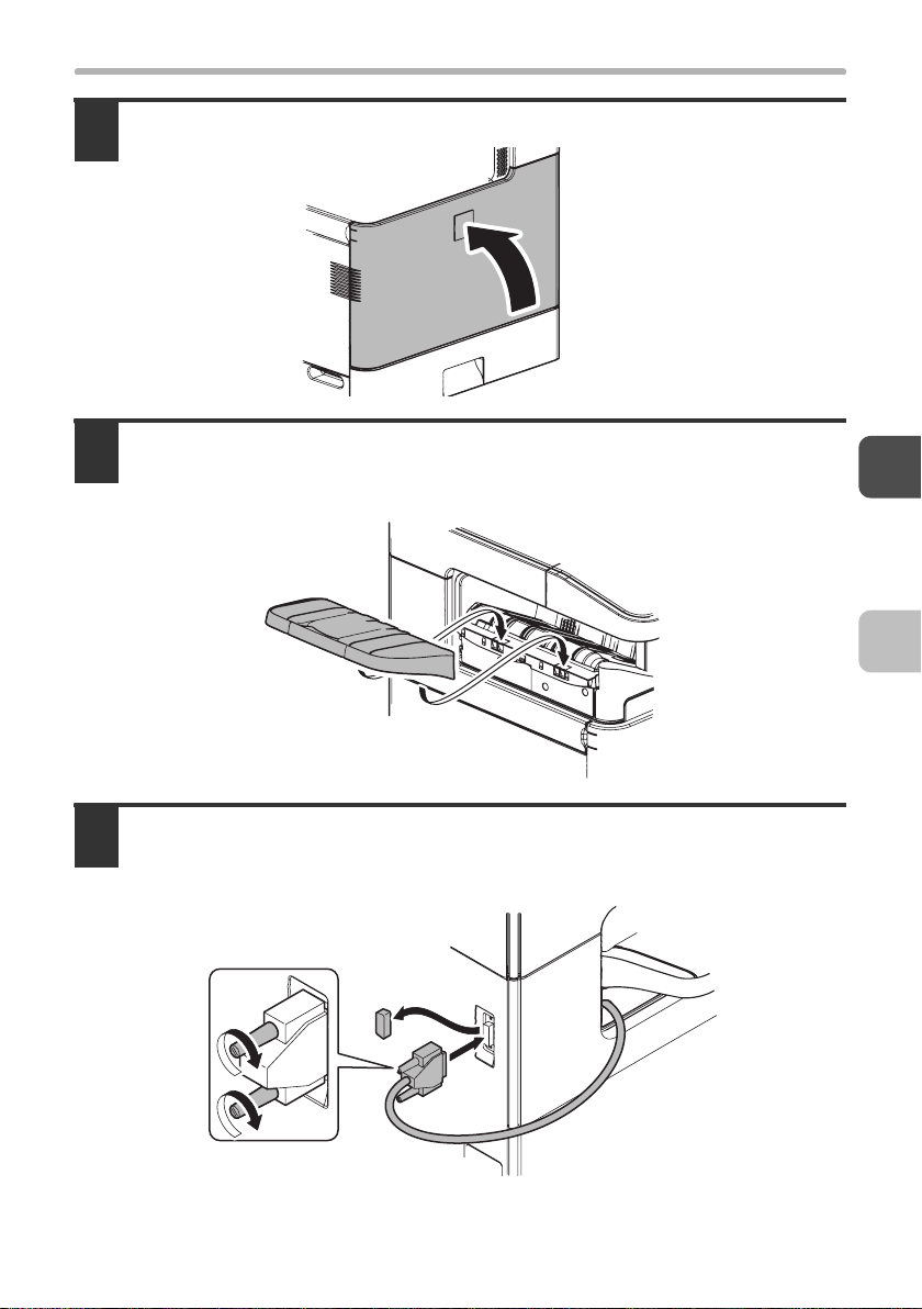
Close the front cover of the main unit.
11
Install the paper exit tray (included in the package) to the finisher.
12
Attach the paper exit tray to the finisher by inserting the catches into the slots (two)
on the finisher.
Remove the cap from the connector for the finisher on the back of the
13
main unit, and connect the I/F cable of the finisher to the connector.
Tighten the finger screws to secure the I/F cable connector.
21
Page 24
INSTALLING THE FINISHER
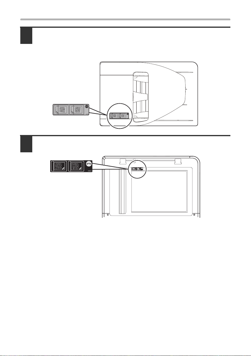
Attach the staple position label (included in the package) for the
14
automatic document feeder to the automatic document feeder unit.
There are two types of staple position labels. Take care to attach the correct label
(see step 2).
Attach the staple position label (included in the package) for the
15
document glass to the scanner unit.
22
Page 25
3
This section explains how to install the developer cartridges and operation
manual pocket that accompany the machine. Install these items in the order
described in this manual.
INSTALLING THE ACCESSORIES
Be sure to install the accessories before turning on the main power of the
machine.
INSTALLING THE DEVELOPER
CARTRIDGE
To replace a developer cartridge, see the Maintenance & Safety Guide.
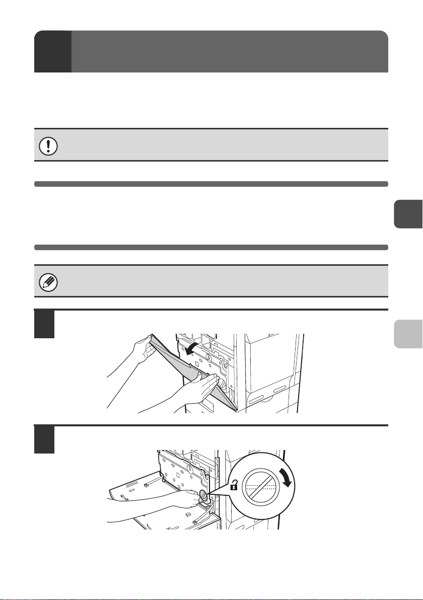
Open the front cover.
1
Turn the toner collection container lock lever to the right until it is horizontal.
2
23
Page 26
INSTALLING THE DEVELOPER CARTRIDGE
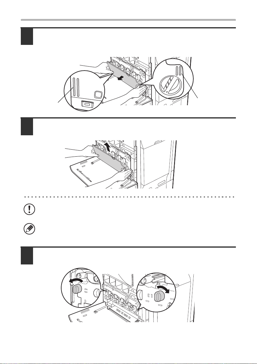
Tip the toner collection container forward.
3
Grasp the toner collection container with both hands at the marks on the upper right
and lower left of the container and slowly tip the container toward you.
Mark
Remove the toner collection container.
4
Hold the container by both hands and lift it up slowly.
If the toner collection container is tipped forward too far, it will not be possible to
remove it.
Hold the container by both hands and lift it up slowly.
Turn the main charger cover lock levers in the direction of an arrow below.
5
When the lock levers are horizontal, the lock is released.
Mark
24
Page 27
INSTALLING THE DEVELOPER CARTRIDGE
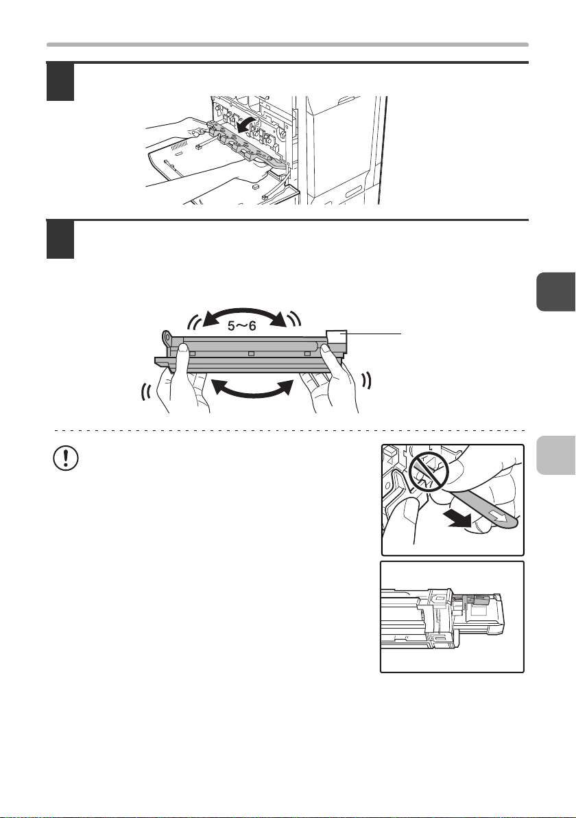
Grasp the lock levers and tip the cover forward.
6
Shake the new developer cartridge 5 or 6 times as shown.
7
Hold the developer cartridge firmly as shown below and shake forward and back,
left and right.
Remove the protective material after shaking the developer cartridge.
Protective
material
• The seal must not be removed when shaking the
new developer cartridge.
• Take care not to damage the developer cartridge
when shaking it. If damaged, the developer in the
cartridge may leak out.
• The part of the developer cartridge shown in the
illustration is easily deformed or damaged. Do
not touch this part when handling the cartridge.
25
Page 28
INSTALLING THE DEVELOPER CARTRIDGE
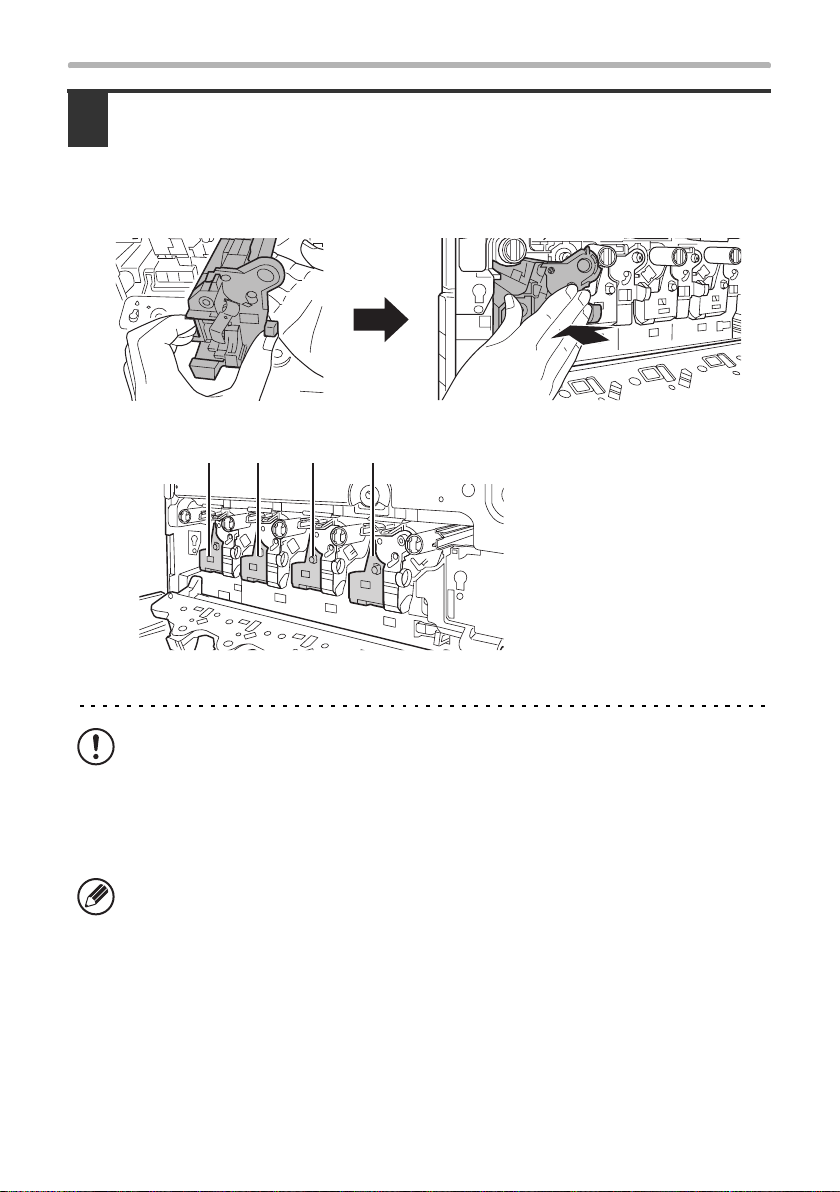
Insert the new developer cartridges (Yellow, Magenta, Cyan and
8
Black) horizontally.
• Support the developer cartridge near the middle with your hand and insert the
new developer cartridges horizontally.
• The shape of the developer cartridge varies by colour.
Locations of developer cartridges
(M)(Y) (C) (Bk)
(Y): Yellow
(M): Magenta
(C): Cyan
(Bk): Black
26
• Do not tilt the developer cartridge or insert it in the wrong direction or
orientation. This may damage the cartridge and the drum or cause a failure.
• When inserting the developer cartridge, grasp it with both hands at the middle.
• Do not remove the seal from the developer cartridge until the cartridge is
installed in the machine. If the seal is removed when the cartridge is not
locked, the cartridge may fall out of the machine.
Insert with the arrow on the cartridge aligned with the arrow on the machine.
Page 29
INSTALLING THE DEVELOPER CARTRIDGE
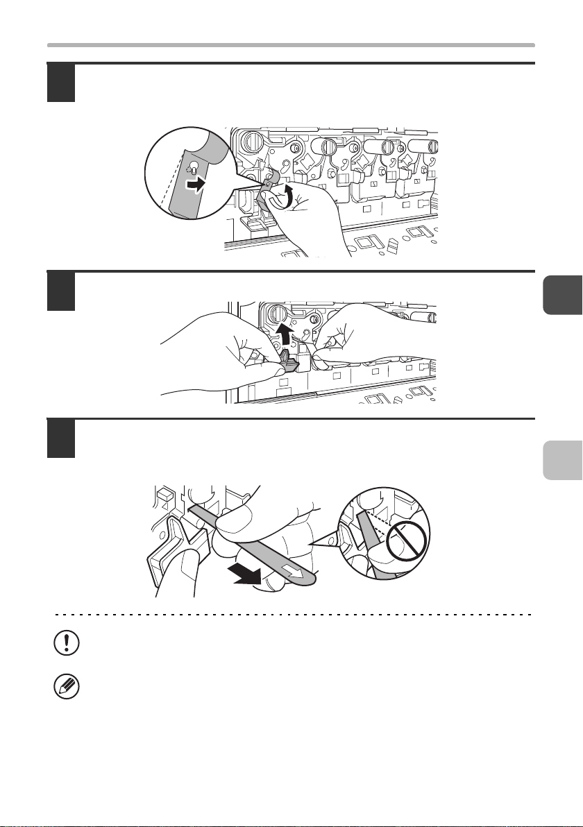
Detach the end of the seal from the developer cartridge.
9
Align the notch in the seal with the tab on the attachment part and pull up. Be
careful not to completely remove the seal by pulling too hard.
Grasp the developer cartridge lock and replace it on the machine.
10
Hold the developer cartridge with one hand and slowly remove the
11
seal with the other hand.
Slowly pull the seal straight and horizontally out.
If excessive force is used or the seal is pulled out diagonally, it may tear.
There is a mark (red belt) on the end of the seal. After removing the seal, be
sure to verify that the mark (red belt) is on the end of the seal.
If the seal has been cut on the developer cartridge, the cartridge cannot be
used. Replace with a new developer cartridge.
27
Page 30
INSTALLING THE DEVELOPER CARTRIDGE
Close the main charger cover and rotate the lock levers in the
12
direction of the arrows to lock the cover.
When the lock levers are vertical, the cover is locked.
This completes the procedure for installing the developer cartridges. Next,
clean the laser unit.
28
Page 31

INSTALLING THE DEVELOPER CARTRIDGE
X Cleaning the laser unit
After installing the developer cartridges for the first time, follow the procedure
below to clean the laser unit.
Remove the cleaning tool for the writing unit from the front cover.
1
Clean the laser unit.
2
(1) Point the cleaner down and slowly insert the tool into the hole
that you wish to clean.
The parts of the writing unit that require cleaning are indicated by labels similar
to (A).
Cleaner
(A)
(2) Insert the cleaning tool all the way into the hole and then pull it
back out.
Pull the cleaning tool out until you feel the tip of the tool leave the cleaning
surface of the laser unit.
29
Page 32

INSTALLING THE DEVELOPER CARTRIDGE
(3) Repeat step (2) two or three times and then remove the
cleaning tool.
Repeat step 2 to clean all holes in the laser unit.
3
Holes to be cleaned
There are a total of 4 holes to be cleaned in the laser unit.
Replace the cleaning tool.
4
30
Page 33

INSTALLING THE DEVELOPER CARTRIDGE
Install the toner collection container.
5
Insert the container from above at a slant. (The direction opposite to when you
removed it.)
(2)
(1)
Turn the lock lever on the toner collection container to the left.
6
Turn the lock lever to the left until it stops.
If the lock lever does not turn, check if the toner collection container is installed
correctly.
Close the front cover.
7
31
Page 34

INSTALLING THE OPERATION
MANUAL POCKET
Install the operation manual pocket (included in package) to the left side of the
machine.
First, insert the pawl on the lower side of the operation manual pocket.
Then, lift the pawl on the upper side and insert it, and slide down to install.
32
Page 35

LOADING PAPER
The procedure for loading paper in the paper trays for the first time is explained
below. For the sizes and types of paper that can be loaded in each tray, see the
Maintenance and Safety Guide. To add paper to a tray, see the Quick Start
Guide.
Pull out the paper tray.
1
Gently pull the tray out until it stops.
Do not pull hard on the tray. This may cause failure.
Adjust the guide plates A and B by squeezing their lock levers and
2
sliding them to match the vertical and horizontal dimensions of the
paper to be loaded.
The guide plates A and B are slidable. Slide each guide plate while squeezing its lock lever.
A
B
Be sure to place the guide to match the size of the paper. If the guide is not
placed correctly, paper skewing or misfeeds may occur.
33
Page 36

LOADING PAPER
Fan the paper.
3
Fan the paper well before loading it. If the paper is not fanned, multiple sheets may
feed at once and cause a misfeed.
When handling paper, take care not to cut yourself on the edges of the paper.
Insert the paper into the tray.
4
Load the paper with the print side face up. The stack must not be higher than the
indicator line (maximum of 500 sheets).
34
Indicator
line
• If paper is loaded higher than the line, paper misfeeds may occur.
• When pushing in a tray, take care that your fingers do not become pinched in
the tray.
Page 37

LOADING PAPER
Gently push the paper tray into the machine.
5
Push the tray firmly all the way into the machine.
When pulling out a tray after paper is loaded, do not pull hard. The tray may be
damaged, the machine may topple, and injury may result.
Caution
If children are present, ensure that the children do not sit or play on a tray that
has been pulled out. Sitting on a tray may damage the tray and cause the
machine to topple, resulting in injury.
Do not place heavy objects on the tray or press down on the tray.
35
Page 38
TURNING ON THE POWER AND
4
This section explains how to turn on the power and adjust the image quality,
which is done after turning on the power.
ADJUSTING THE IMAGE QUALITY
POWER-ON AND AUTO ADJUSTMENT
OF THE DEVELOPER
The machine has two power switches. One is the main power switch on the left
side of the machine, and the other is the [POWER] key ( ) on the upper right
side of the operation panel.
When the power of the machine is turned on for the first time, developer adjustment starts
automatically. Follow the on-screen instructions to complete auto developer adjustment.
Several minutes may be needed to complete the auto developer adjustment.
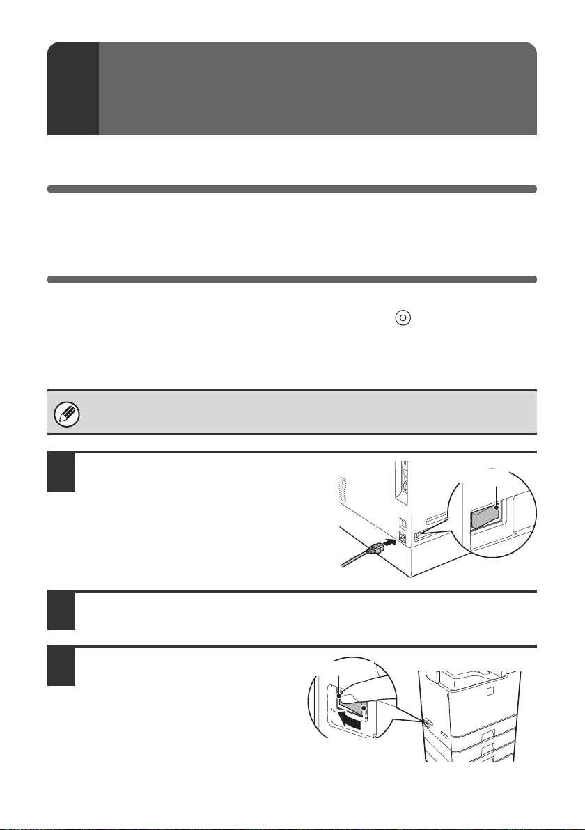
Ensure that the main power switch
1
of the machine is in the "off"
position. Insert the attached power
cord into the power cord socket at
the rear of the machine.
"Off" position
Insert the power plug into the power outlet.
2
Switch the main power switch
3
to the "on" position.
When the main power switch is
switched on, the main power
indicator on the operation panel
lights up.
36
"On" position
"Off" position
Page 39

INSTALLING THE TONER CARTRIDGE
Press the [POWER] key ( ) on the operation panel to turn on the power.
4
When the power is turned on, developer adjustment begins automatically.
Main power indicator
[POWER] key
During auto developer adjustment, do not open the front cover or right side
cover, and do not turn off the power. This may cause degraded image quality.
INSTALLING THE TONER CARTRIDGE
When installing the toner cartridges for the first time, install the cartridges after
the power has been turned on and auto adjustment of the developer is finished.
To replace a toner cartridge, see the Maintenance & Safety Guide.
Take out the new toner cartridge, hold it with both hands, and shake 5
1
or 6 times horizontally.
Protective
material
• When shaking the toner cartridge, be sure to shake with the protective
material inserted in the cartridge. If you shake the cartridge after removing the
protective material, toner may spill out.
• Shake the toner cartridge only in the horizontal direction. If shaken in any
other direction, toner may collect in one part of the cartridge.
37
Page 40

INSTALLING THE TONER CARTRIDGE
Remove the protective material from the new toner cartridge.
2
• Hold the toner cartridge firmly while removing the protective material.
• After the protective material has been removed, do not point the toner
cartridge down or shake it. Toner may spill out.
Open the front cover.
3
Insert the new toner cartridges (Yellow, Magenta, Cyan and Black)
4
horizontally and push it firmly in.
The shape of the toner cartridge varies by colour. Insert in the same location as the
toner cartridge that was removed.
Locations of colour toner cartridges
(M)(Y) (C) (Bk)
(Y): Yellow
(M): Magenta
(C): Cyan
(Bk): Black
38
Page 41

INSTALLING THE TONER CARTRIDGE
Close the front cover.
5
When the front cover is closed, image quality adjustment begins automatically.
During image quality adjustment, do not open the front cover or right side cover,
and do not turn off the power. This may cause degraded image quality.
When image adjustment ends and the base screen of copy mode appears
in the display, hardware installation is completed.
• After installing the machine, if you will be using the printer function or the
scanner function, install the necessary software as explained in Part 2,
"SOFTWARE INSTALLATION" (page 41).
• To gain a general understanding of how to use the machine, read the Quick
Start Guide. The Quick Start Guide explains the basic procedures for
operating the machine.
• To turn off the power of the machine, see "TURNING OFF THE POWER OF
THE MACHINE" (page 40).
39
Page 42

TURNING OFF THE POWER OF
THE MACHINE
To turn off the power of the machine, make sure that the LINE indicator and the
DATA indicator on the operation panel are off, and then follow the steps in the
order shown below.
Press the [POWER] key ( ) on the operation panel to turn off the power.
1
Wait 20 seconds and then switch off the main power switch.
2
"On" position
"Off" position
Disconnect the power plug from the power outlet.
3
Important rules when turning off the main power
When turning off the main power, always turn off the operation panel
power first, wait at least 20 seconds, and then turn off the main power.
If you turn off the main power without turning off the operation panel power, or
do not wait at least 20 seconds before turning off the main power, machine
failure may result.
If the main power is suddenly interrupted due to a power failure or other reason,
turn the machine power back on and then turn it off correctly as described above.
40
Page 43

PART 2
SOFTWARE INSTALLATION
PART 2
SOFTWARE INSTALLATION
BEFORE INSTALLING
THE SOFTWARE
SETUP IN A WINDOWS
ENVIRONMENT
SETUP IN A MACINTOSH
ENVIRONMENT
TROUBLESHOOTING
41
Page 44

This part explains how to install and configure the software that allows the
machine to be used as a printer or scanner for a computer.
This part also explains how to install the printer drivers and software that are used
when the expansion kits are installed, and how to install the scanner driver.
If the software is not installed correctly or you need to remove the software, see
"4. TROUBLESHOOTING" (page 106).
Please note
• The explanations in this manual assume that you have a working knowledge of
your Windows or Macintosh computer.
• For information on your operating system, please refer to your operating system
manual or the online Help function.
•
The explanations of screens and procedures in this manual are primarily for Windows
®
Vista
in Windows® environments, and Mac OS X v10.4 in Macintosh environments.
The screens may vary depending on the version of the operating system.
• Wherever "DX-xxxx" appears in this manual, please substitute your model name
for "xxxx".
SOFTWARE LICENSE
The SOFTWARE LICENSE will appear when you install the software from the
CD-ROM. By using all or any portion of the software on the CD-ROM or in the
machine, you are agreeing to be bound by the terms of the SOFTWARE LICENSE.
For users of Windows 98/Me/NT 4.0
The CD-ROM does not include software for Windows 98/Me/NT 4.0.
Contact your dealer or nearest authorised service representative if you want software
for Windows 98/Me/NT 4.0.
The scanner driver cannot be installed on Windows NT 4.0.
42
Page 45

TABLE OF CONTENTS
BEFORE INSTALLING THE SOFTWARE
1
CD-ROMS AND SOFTWARE . . . . . . . . . . . . . . . . . . . . . . . . . . . . . . . . . . . . . . . . . . . . 44
• SOFTWARE CD-ROM . . . . . . . . . . . . . . . . . . . . . . . . . . . . . . . . . . . . . . . . . . . . . . 44
• OTHER CD-ROMS. . . . . . . . . . . . . . . . . . . . . . . . . . . . . . . . . . . . . . . . . . . . . . . . . 46
VERIFYING SYSTEM REQUIREMENTS . . . . . . . . . . . . . . . . . . . . . . . . . . . . . . . . . . . 47
• SYSTEM REQUIREMENTS. . . . . . . . . . . . . . . . . . . . . . . . . . . . . . . . . . . . . . . . . . 47
• SOFTWARE REQUIREMENTS . . . . . . . . . . . . . . . . . . . . . . . . . . . . . . . . . . . . . . . 48
CONNECTING THE MACHINE. . . . . . . . . . . . . . . . . . . . . . . . . . . . . . . . . . . . . . . . . . . 49
• CONNECTING TO A NETWORK. . . . . . . . . . . . . . . . . . . . . . . . . . . . . . . . . . . . . . 49
• CONNECTING THE MACHINE WITH A USB CABLE (Windows). . . . . . . . . . . . . 49
SETUP IN A WINDOWS ENVIRONMENT
2
OPENING THE SOFTWARE SELECTION SCREEN (FOR ALL SOFTWARE) . . . . . 50
INSTALLING THE PRINTER DRIVER / PC-FAX DRIVER. . . . . . . . . . . . . . . . . . . . . . 52
• WHEN THE MACHINE IS CONNECTED TO A NETWORK . . . . . . . . . . . . . . . . . 52
• WHEN THE MACHINE WILL BE CONNECTED WITH A USB CABLE . . . . . . . . . 64
• USING THE MACHINE AS A SHARED PRINTER . . . . . . . . . . . . . . . . . . . . . . . . 72
• USING THE STANDARD WINDOWS PS PRINTER DRIVER (Windows
98/Me/NT 4.0). . . . . . . . . . . . . . . . . . . . . . . . . . . . . . . . . . . . . . . . . . . . . . . . . . . . . 75
• CONFIGURING THE PRINTER DRIVER FOR THE OPTIONS INSTALLED
ON THE MACHINE . . . . . . . . . . . . . . . . . . . . . . . . . . . . . . . . . . . . . . . . . . . . . . . . 77
INSTALLING THE PRINTER STATUS MONITOR. . . . . . . . . . . . . . . . . . . . . . . . . . . . 82
INSTALLING THE SCANNER DRIVER . . . . . . . . . . . . . . . . . . . . . . . . . . . . . . . . . . . . 84
INSTALLING THE PS DISPLAY FONTS (DX-C310/C380) . . . . . . . . . . . . . . . . . . . . . 87
CHANGING THE PORT . . . . . . . . . . . . . . . . . . . . . . . . . . . . . . . . . . . . . . . . . . . . . . . . 89
SETUP IN A MACINTOSH ENVIRONMENT
3
MAC OS X . . . . . . . . . . . . . . . . . . . . . . . . . . . . . . . . . . . . . . . . . . . . . . . . . . . . . . . . . . . 92
MAC OS 9.0 - 9.2.2 . . . . . . . . . . . . . . . . . . . . . . . . . . . . . . . . . . . . . . . . . . . . . . . . . . . 102
TROUBLESHOOTING
4
WHEN INSTALLATION WAS NOT SUCCESSFUL . . . . . . . . . . . . . . . . . . . . . . . . . . 106
REMOVING THE SOFTWARE . . . . . . . . . . . . . . . . . . . . . . . . . . . . . . . . . . . . . . . . . . 111
43
Page 46

BEFORE INSTALLING THE
1
This chapter describes the software programs that allow you to use the printer
and scanner functions of the machine, the CD-ROMs that contain the software,
and the pages where the installation procedures can be found.
SOFTWARE
CD-ROMS AND SOFTWARE
The software that can be used with the machine is on the CD-ROMs that
accompany the machine and the expansion kits.
Before installing the software, make sure that your computer and the machine
meet the system requirements described in "VERIFYING SYSTEM
REQUIREMENTS" (page 47).
SOFTWARE CD-ROM
The "Software CD-ROM" that accompanies the machine contains the printer
driver and other software. The "Software CD-ROM" consists of 2 discs.
For users of Windows 98/Me/NT 4.0
The CD-ROM does not include software for Windows 98/Me/NT 4.0.
Contact your dealer or nearest authorised service representative if you want
software for Windows 98/Me/NT 4.0.
Disc 1
Software for Windows
• Printer driver
These allow the machine to be used as a printer.
- PCL6 and PCL5c printer driver
The machine supports the Hewlett-Packard PCL6 and PCL5c printer
control languages. It is recommended that you use the PCL6 printer driver.
If you have a problem printing from older software using the PCL6 printer
driver, use the PCL5c printer driver.
- PS printer driver
The PS printer driver supports the PostScript 3 page description language
developed by Adobe Systems Incorporated.
44
Page 47

CD-ROMS AND SOFTWARE
- PPD driver
The PPD driver enables the machine to use the standard Windows PS
printer driver.
☞ WHEN THE MACHINE IS CONNECTED TO A NETWORK (page 52)
☞ WHEN THE MACHINE WILL BE CONNECTED WITH A USB CABLE
(page 64)
• Printer Status Monitor (can only be used when the machine is
connected to a network)
This allows you to monitor the status of the machine on your computer screen.
☞ INSTALLING THE PRINTER STATUS MONITOR (page 82)
Disc 2
Software for Windows
• PC-Fax driver
This enables you to send a file from your computer as a fax using the same
procedure as when printing the file. (When the fax option is installed.)
Even if the fax function is not installed, the PC-Fax driver can be updated
using the CD-ROM in the Internet fax expansion kit to enable you to send a
file from your computer as an Internet fax in the same way as you print a file.
☞ INSTALLING THE PRINTER DRIVER / PC-FAX DRIVER (page 52)
The following software can be used only when the machine is connected
to a network.
• Scanner driver (TWAIN driver)
This allows you to use the scanner function of the machine from a
TWAIN-compliant software application.
☞ INSTALLING THE SCANNER DRIVER (page 84)
• Printer Administration Utility
This allows the administrator to monitor the machine and configure machine
settings from a computer. To install and use the Printer Administration Utility,
see the Readme file and the manual in PDF format on the "Software
CD-ROM" (Disc 2). The Readme file and manual are in the following folder on
the CD-ROM. (Substitute the letter of your CD-ROM drive for "R" in the
following path.)
R:\Sadmin\Documents\English
45
Page 48

CD-ROMS AND SOFTWARE
Software for Macintosh
• PPD file
This is the printer description file which enables the machine to be used as a
PostScript 3 compatible printer.
☞ MAC OS X (page 92)
☞ MAC OS 9.0 - 9.2.2 (page 102)
• To use the machine as a printer in a Macintosh environment, the machine
must be connected to a network. A USB connection cannot be used.
• If you are using the DX-C310/C380, the PS3 expansion kit is required to
use the machine as a printer in a Macintosh environment.
• The scanner driver and PC-Fax driver cannot be used in a Macintosh
environment.
OTHER CD-ROMS
X
"PRINTER UTILITIES" CD-ROM that accompanies
the Internet fax expansion kit (for Windows)
This CD-ROM is used to update the PC-Fax driver on the "Software
CD-ROM" so that it can be used to send Internet faxes (PC-I-Fax function).
If you wish to use the PC-I-Fax function, first install the PC-Fax driver from
the "Software CD-ROM" and then run the installer on this CD-ROM. If the
PC-Fax driver is already installed, run only the installer. (There is no need to
reinstall the PC-Fax driver.)
☞INSTALLING THE PRINTER DRIVER / PC-FAX DRIVER (page 52)
X
"Sharpdesk/Network Scanner Utilities" CD-ROM
(for Windows)
This contains software that helps you get the most out of the images that you scan
on the machine. The software includes "Sharpdesk", a desktop document
management application that enables integrated management of scanned images
and files created using a variety of applications. To use the "Scan to Desktop"
scanner function, the "Network Scanner Tool" must be installed from the CD-ROM.
For the system requirements of the software, see the manual (PDF format) in
the "Manual" folder or the Readme file on the CD-ROM. For the procedures
for installing the software, see the "Sharpdesk Installation Guide".
X
"PRINTER UTILITIES" CD-ROM that accompanies
the PS3 expansion kit (for DX-C310/C380)
This contains the display fonts that are used with the PS printer driver.
(Install the PS printer driver and Macintosh PPD file from the "Software CD-ROM".)
☞ INSTALLING THE PS DISPLAY FONTS (DX-C310/C380) (page 87)
46
Page 49

VERIFYING SYSTEM REQUIREMENTS
SYSTEM REQUIREMENTS
Before installing the software described in this manual, make sure that your
computer satisfies the following requirements.
Windows Macintosh*
Operating
*1
system
Computer type IBM PC/AT compatible computer
Display 1024 x 768 dots resolution and 16-bit
Other hardware
requirements
*1 Printing is not possible in MS-DOS mode.
*2 USB is not supported. The scanner driver cannot be installed.
*3 The machine's USB 2.0 port will transfer data at the speed specified by the USB 2.0
(Hi-Speed) standard only if the Microsoft USB 2.0 driver is preinstalled in the
computer, or if the USB 2.0 driver for Windows 2000 Professional/XP/Vista that
Microsoft provides through "Windows Update" is installed.
*4 Compatible with models preinstalled with Windows 98, Windows Me, Windows 2000
Professional, Windows XP Professional, Windows XP Home Edition, Windows 2000
Server, Windows Server 2003, Windows Vista, or Windows Server 2008 and which
are equipped standard with a USB interface.
*5 Cannot be used when the machine is connected with a USB cable. The PC-Fax driver
and scanner driver cannot be used.
Windows 98, Windows Me,
Windows NT Workstation 4.0 (Service Pack 5
or later)*
Windows XP Professional, Windows XP Home
Edition, Windows 2000 Server,
Windows Server 2003, Windows Vista,
Windows Server 2008
Equipped with a
10Base-T/100Base-TX/1000Base-T LAN
board or equipped standard with a USB
2.0
colour or higher is recommended.
An environment that allows any of the above
operating systems to fully operate.
2
, Windows 2000 Professional,
*3
/1.1*4 port.
Mac OS 9.0 to 9.2.2,
Mac OS X v10.2.8,
Mac OS X v10.3.9,
Mac OS X v10.4.11,
Mac OS X v10.5 to
10.5.1
An environment in
which any of the
operating systems listed
above can fully operate
(including Macintosh
computers with an Intel
processor).
5
• For users of Windows 98/Me/NT 4.0
The CD-ROM does not include software for Windows 98/Me/NT 4.0.
Contact your dealer or nearest authorised service representative if you want
software for Windows 98/Me/NT 4.0.
• For users of Windows NT 4.0/2000/XP/Server 2003/Vista/Server 2008
To perform the procedures described in this manual such as installing the software
and configuring settings after installation, administrator authority is required.
47
Page 50

VERIFYING SYSTEM REQUIREMENTS
SOFTWARE REQUIREMENTS
The following requirements must be met to use the software described in this
manual.
Operating
system
environment*
Windows PCL6 printer
Macintosh Macintosh PPD
Software
1
driver,
PCL5c printer
driver
PS printer
driver,
PPD driver
PC-Fax driver*2Facsimile expansion kit*
Scanner driver
Printer Status
Monitor
Printer
Administration
Utility
file
Required expansion kits
DX-C310/C380 DX-C311/C381
Can be used in the standard
configuration.
PS3 expansion kit
3
Can be used in the standard
configuration.
PS3 expansion kit
Type of
connection*
Network/ USB
Network only
(cannot be used
with a USB
connection)
1
*1 For the types of computers and operating systems that can run the software,
see "SYSTEM REQUIREMENTS" (page 47).
*2 To use the PC-Fax driver, Internet Explorer 4.0 or later must be installed on
your computer.
*3 When the Internet fax expansion kit is installed, the PC-Fax driver can be
updated using the "PRINTER UTILITIES" CD-ROM to enable the driver to be
used as a PC-I-Fax driver. In this case, the driver can be used without the
facsimile expansion kit.
48
Page 51

CONNECTING THE MACHINE
CONNECTING TO A NETWORK
To connect the machine to a network, connect the LAN cable to the machine's
network connector. Use a shielded LAN cable.
After connecting the machine to a network, be sure to configure the IP address
and other network settings before installing the software. (The factory default
setting for the IP address is to receive the IP address automatically when the
machine is used in a DHCP environment.)
Network settings can be configured using "Network Settings" in the system
settings (administrator) on the machine.
•
If the machine is used in a DHCP environment, the IP address of the machine may
change. If this happens, printing will not be possible. This problem can be avoided by
using a WINS server or by assigning a permanent IP address to the machine.
• This manual explains how to set up the software in a Windows network
environment and in a Macintosh network environment.
X Checking the IP address of the machine
You can check the IP address by pressing the [SYSTEM SETTINGS] key on the
machine and printing out the "All Custom Setting List" from [List Print (User)].
CONNECTING THE MACHINE WITH A USB
CABLE (Windows)
The machine can be connected to a computer using a USB cable if the
computer is a Windows computer. (The USB interface on the machine cannot
be used in a Macintosh environment.)
The machine and computer should be connected while the printer driver is
being installed. If a USB cable is connected before the printer driver is installed,
the printer driver will not be installed correctly. For the procedure for connecting
a USB cable, see "WHEN THE MACHINE WILL BE CONNECTED WITH A
USB CABLE" (page 64).
49
Page 52

2
This section explains how to install the software and configure settings so that
the printer and scanner function of the machine can be used with a Windows
computer.
SETUP IN A WINDOWS ENVIRONMENT
For users of Windows 98/Me/NT 4.0
The CD-ROM does not include software for Windows 98/Me/NT 4.0.
Contact your dealer or nearest authorised service representative if you want
software for Windows 98/Me/NT 4.0.
OPENING THE SOFTWARE SELECTION
SCREEN (FOR ALL SOFTWARE)
Insert the "Software CD-ROM" into your computer's CD-ROM drive.
1
• If you are installing the printer driver or printer status monitor, insert the
"Software CD-ROM" that shows "Disc 1" on the front of the CD-ROM.
• If you are installing the PC-Fax driver or scanner driver, insert the "Software
CD-ROM" that shows "Disc 2" on the front of the CD-ROM.
Click the [Start] button ( ), click [Computer], and then double-click
2
the [CD-ROM] icon ( ).
• In Windows XP/Server 2003, click the [start] button, click [My Computer], and
then double-click the [CD-ROM] icon.
• In Windows 2000, double-click [My Computer] and then double-click the
[CD-ROM] icon.
Double-click the [Setup] icon ( ).
3
In Windows Vista/Server 2008, if a message screen appears asking you for
confirmation, click [Allow].
50
Page 53

OPENING THE SOFTWARE SELECTION SCREEN (FOR ALL SOFTWARE)
The "SOFTWARE LICENSE" window will appear. Make sure that you
4
understand the contents of the license agreement and then click the
[Yes] button.
You can show the "SOFTWARE LICENSE" in a different language by selecting
the desired language from the language menu. To install the software in the
selected language, continue the installation with that language selected.
Read the message in the "Welcome" window and then click the [Next]
5
button.
The software selection screen appears.
6
Before installing the software, be sure to click the [Display Readme] button and
view the detailed information on the software.
*The above screen appears when using the "Disc 1" CD-ROM.
For the steps that follow, see the appropriate page below for the software that
you are installing.
INSTALLING THE PRINTER DRIVER / PC-FAX DRIVER
• WHEN THE MACHINE IS CONNECTED TO A NETWORK
- Standard installation: page 53
- Installation by specifying the machine's address: page 57
- Printing using the IPP function and the SSL function: page 61
• WHEN THE MACHINE WILL BE CONNECTED WITH A USB CABLE: page 64
• USING THE MACHINE AS A SHARED PRINTER: page 72
INSTALLING THE PRINTER STATUS MONITOR: page 82
INSTALLING THE SCANNER DRIVER: page 84
51
Page 54

INSTALLING THE PRINTER
DRIVER / PC-FAX DRIVER
To install the printer driver or the PC-Fax driver, follow the appropriate
procedure in this section depending on whether the machine is connected to a
network or connected by USB cable.
☞
WHEN THE MACHINE WILL BE CONNECTED WITH A USB CABLE (page 64)
WHEN THE MACHINE IS CONNECTED TO A
NETWORK
This section explains how to install the printer driver and the PC-Fax driver
when the machine is connected to a Windows network (TCP/IP network).
*
Supported operating systems: Windows 98/Me/NT 4.0
Server 2003
* Administrator's rights are required to install the software.
*
/Vista*/Server 2008
• If you are using the DX-C310/C380, the PS3 expansion kit is required to use
the PS printer driver or the PPD driver.
•
To install the PPD driver when Windows 98/Me/NT 4.0 is used, see "USING
THE STANDARD WINDOWS PS PRINTER DRIVER (Windows 98/Me/NT 4.0)"
(page 75) and install the driver using the Add Printer Wizard.
• To use the machine as a network printer in Windows NT 4.0, "TCP/IP
Protocol" must be installed on your computer. If this is not installed, see
Windows NT 4.0 Help to install "TCP/IP Protocol".
• To print to the machine over the Internet using the IPP function when
the machine is installed in a remote location, or to print using the SSL
(encrypted communication) function, see "Printing using the IPP
function and the SSL function" (page 61) and install the printer driver or
the PC-Fax driver.
• If the machine is connected to an IPv6-only network, the software
cannot be installed by detecting or specifying the machine's address
from the installer.
• The installation procedure in this section is for both the printer driver and the
PC-Fax driver, although the explanations are centred on the printer driver.
*
/2000*/XP*/
52
Page 55
INSTALLING THE PRINTER DRIVER / PC-FAX DRIVER
X Standard installation
When the software selection screen appears in step 6 of "OPENING THE
SOFTWARE SELECTION SCREEN (FOR ALL SOFTWARE)" (page 50),
perform the steps below.
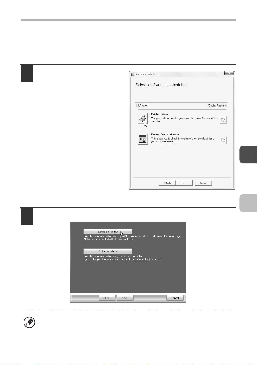
Click the [Printer Driver]
1
button.
To install the PC-Fax driver, click the
[PC-Fax Driver] button on the
"Disc 2" CD-ROM.
*The above screen appears when using the "Disc 1" CD-ROM.
Click the [Standard installation] button.
2
When [Custom installation] is selected, you can change any of the items below.
When [Standard installation] is selected, the installation will take place as
indicated below.
53
Page 56

INSTALLING THE PRINTER DRIVER / PC-FAX DRIVER
• Machine connection method: LPR Direct Print (Auto Search)
• Set as default printer:Yes (excluding the PC-Fax driver)
• Printer driver name: Cannot be changed
• Display fonts: Installed
If you selected [Custom installation], select [LPR Direct Print (Auto Search)] and
click the [Next] button.
If you selected other than [LPR Direct Print (Auto Search)], see the following
pages:
• LPR Direct Print (Specify Address): page 57
• IPP: page 61
• Shared printer: page 72
• Connected to this computer: page 64
Printers connected to the
3
network are detected.
Select the machine and
click the [Next] button.
• If the machine is not found, make sure that the machine is powered on and
that the machine is connected to the network, and then click the [Re-search]
button.
• You can also click the [Specify condition] button and search for the machine
by entering the machine's name (host name) or IP address.
☞ Checking the IP address of the machine (page 49)
A confirmation window appears. Check the contents and then click
4
the [Next] button.
54
Page 57

INSTALLING THE PRINTER DRIVER / PC-FAX DRIVER
When the printer driver
5
selection window appears,
select the printer driver to
be installed and click the
[Next] button.
Click the checkbox of the printer
driver to be installed so that a
checkmark ( ) appears.
*The screen shows the installer for the DX-C311/C381.
• When the PC-Fax driver is being installed, this screen does not appear. Go to
the next step.
• If you are using the DX-C310/C380, the PS3 expansion kit is required to use
the PS printer driver or the PPD driver.
• The [PPD] checkbox only appears if you are using Windows 2000/XP/
Server 2003/Vista/Server 2008.
When you are asked whether or not you want the printer to be your
6
default printer, make a selection and click the [Next] button.
If you are installing multiple drivers, select the printer driver to be used as the
default printer.
If you do not wish to set one of the printer drivers as the default printer, select [No].
If you clicked the [Custom installation] button in step 2, the following windows
will appear.
• Printer name window
If you wish to change the printer name, enter the desired name and click the
[Next] button.
• Window confirming installation of the display fonts
•If
you wish to install the display fonts, select [Yes] and click the [Next] button.
• When the PC-Fax driver is being installed, this screen does not appear. Go
to the next step.
• If you are using the DX-C310/C380 and are not installing the PCL printer
driver (you are installing the PS printer driver or the PPD driver), select [No]
and click the [Next] button.
55
Page 58

INSTALLING THE PRINTER DRIVER / PC-FAX DRIVER
Follow the on-screen instructions.
7
Read the message in the window that appears and click the [Next] button.
Installation begins.
• If you are using Windows Vista/Server 2008
If a security warning window appears, be sure to click [Install this driver
software anyway].
• If you are using Windows 2000/XP/Server 2003
If a warning message regarding the Windows logo test or digital signature
appears, be sure to click the [Continue Anyway] or [Yes] button.
When the installation completed screen appears, click the [OK]
8
button.
Click the [Close] button in the window of step 1.
9
After the installation, a message prompting you to restart your computer may
appear. If this message appears, click the [Yes] button to restart your computer.
This completes the installation.
• After installation, see "CONFIGURING THE PRINTER DRIVER FOR THE
OPTIONS INSTALLED ON THE MACHINE" (page 77) to configure the printer
driver settings.
• If you are using the machine as a shared printer, see "USING THE MACHINE
AS A SHARED PRINTER" (page 72) to install the printer driver on each of the
client computers.
• If you are using the DX-C310/C380 and have installed the PS printer driver or
the PPD driver, the PS display fonts can be installed from the "PRINTER
UTILITIES" CD-ROM that accompanies the PS3 expansion kit. See
"INSTALLING THE PS DISPLAY FONTS (DX-C310/C380)" (page 87).
56
Page 59

INSTALLING THE PRINTER DRIVER / PC-FAX DRIVER
X
Installation by specifying the machine's address
When the machine cannot be found because it is not powered on or otherwise,
installation is possible by entering the name (host name) or IP address of the machine.
When the software selection screen appears in step 6 of "OPENING THE
SOFTWARE SELECTION SCREEN (FOR ALL SOFTWARE)" (page 50),
perform the steps below.
Click the [Printer Driver] button.
1
To install the PC-Fax driver, click the [PC-Fax Driver] button on the "Disc 2" CD-ROM.
*The above screen appears when using the "Disc 1" CD-ROM.
Click the [Custom installation] button.
2
57
Page 60

INSTALLING THE PRINTER DRIVER / PC-FAX DRIVER
When you are asked how the printer is connected, select [LPR Direct
3
Print (Specify Address)] and click the [Next] button.
Enter the name (host name) or IP address of the machine and click
4
the [Next] button.
☞ Checking the IP address of the machine (page 49)
When the model selection window appears, select the model name of
5
your machine and click the [Next] button.
58
Page 61

INSTALLING THE PRINTER DRIVER / PC-FAX DRIVER
When the printer driver selection window appears, select the printer
6
driver to be installed and click the [Next] button.
Click the checkbox of the printer driver to be installed so that a checkmark ( )
appears.
*The screen shows the installer for the DX-C311/C381.
• When the PC-Fax driver is being installed, this screen does not appear. Go to
the next step.
• If you are using the DX-C310/C380, the PS3 expansion kit is required to use
the PS printer driver or the PPD driver.
• The [PPD] checkbox only appears if you are using Windows 2000/XP/
Server 2003/Vista/Server 2008.
Select whether or not you wish the printer to be your default printer
7
and click the [Next] button.
If you are installing multiple drivers, select the printer driver to be used as the
default printer.
If you do not wish to set one of the printer drivers as the default printer, select [No].
When the printer name window appears, click the [Next] button.
8
If you wish to change the printer name, enter the desired name and click the [Next] button.
When you are asked if you wish to install the display fonts, select an
9
answer and click the [Next] button.
• If you are using the DX-C310/C380 and are not installing the PCL printer driver
(you are installing the PS printer driver or the PPD driver), select [No] and click
the [Next] button.
• When the PC-Fax driver is being installed, this screen does not appear. Go to
the next step.
59
Page 62

INSTALLING THE PRINTER DRIVER / PC-FAX DRIVER
Follow the on-screen instructions.
10
Read the message in the window that appears and click the [Next] button.
Installation begins.
• If you are using Windows Vista/Server 2008
If a security warning window appears, be sure to click [Install this driver
software anyway].
• If you are using Windows 2000/XP/Server 2003
If a warning message regarding the Windows logo test or digital signature
appears, be sure to click the [Continue Anyway] or [Yes] button.
When the installation completed screen appears, click the [OK]
11
button.
Click the [Close] button in the window of step 1.
12
After the installation, a message prompting you to restart your computer may
appear. If this message appears, click the [Yes] button to restart your computer.
This completes the installation.
• After installation, see "CONFIGURING THE PRINTER DRIVER FOR THE
OPTIONS INSTALLED ON THE MACHINE" (page 77) to configure the printer
driver settings.
• If you are using the DX-C310/C380 and have installed the PS printer driver or
the PPD driver, the PS display fonts can be installed from the "PRINTER
UTILITIES" CD-ROM that accompanies the PS3 expansion kit. See
"INSTALLING THE PS DISPLAY FONTS (DX-C310/C380)" (page 87).
60
Page 63

INSTALLING THE PRINTER DRIVER / PC-FAX DRIVER
X Printing using the IPP function and the SSL
function
The IPP function can be used to print to the machine over a network using
HTTP protocol.
When the machine is in a remote location, this function can be used in place of
the fax function to print a higher quality image than a fax. The IPP function can
also be used in combination with the SSL (encrypted communication) function
to encrypt the print data. This enables secure printing with no concern that the
data will be leaked to others.
To use the SSL function, configure the "SSL Settings" in the system settings
(administrator) of the machine. To configure the settings, see the "SYSTEM
SETTINGS" chapter in the Operation Guide.
When the software selection screen appears in step 6 of "OPENING THE
SOFTWARE SELECTION SCREEN (FOR ALL SOFTWARE)" (page 50),
perform the steps below.
Click the [Printer Driver] button.
1
To install the PC-Fax driver, click the [PC-Fax Driver] button on the "Disc 2"
CD-ROM.
*The above screen appears when using the "Disc 1" CD-ROM.
61
Page 64

INSTALLING THE PRINTER DRIVER / PC-FAX DRIVER
Click the [Custom installation] button.
2
When you are asked how the printer is connected, select [IPP] and
3
click the [Next] button.
If a proxy server is used, specify the proxy server and click the [Next] button.
4
To specify a proxy server, select [Print via the proxy server] and then enter the
[Address] and [Port number].
62
Page 65
INSTALLING THE PRINTER DRIVER / PC-FAX DRIVER
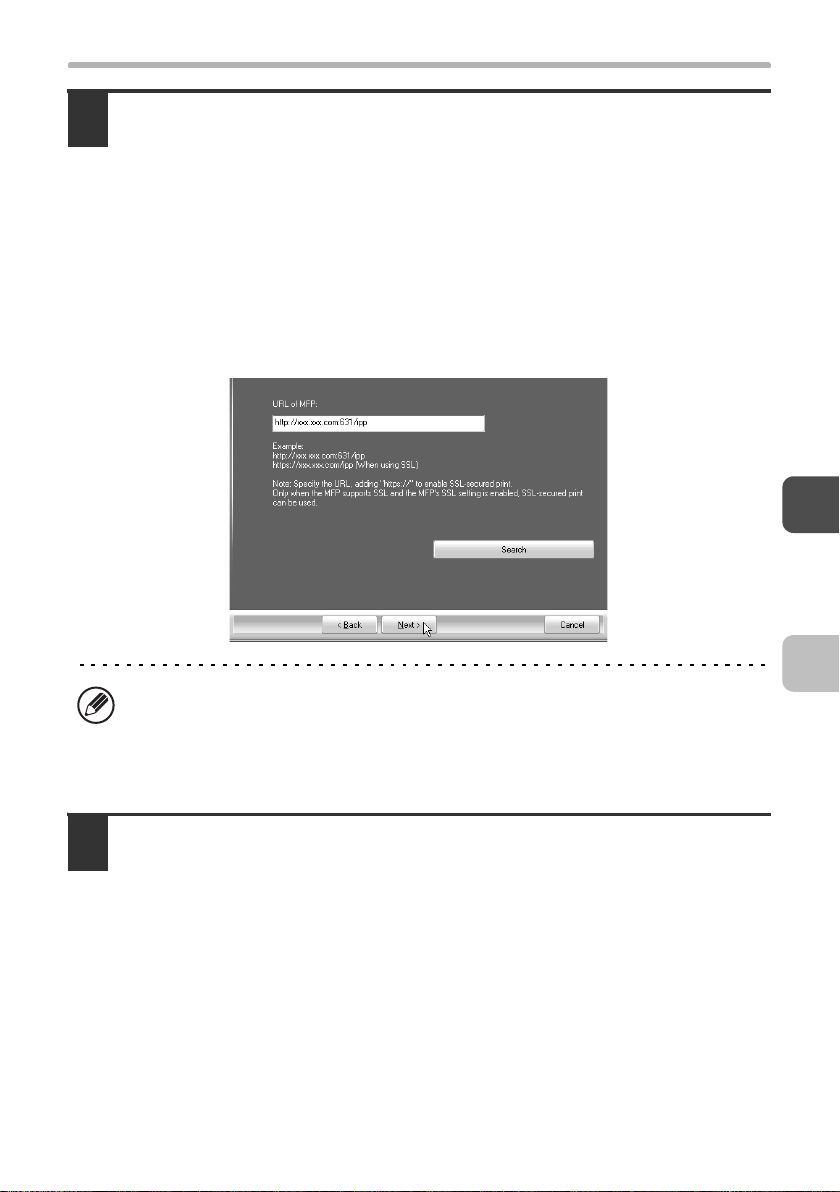
Enter the machine's URL and click the [Next] button.
5
Enter the URL in the following format:
Normal format:
http://<the machine's domain name or IP address>:631*
*1 Normally "631" should be entered for the port number. If the IPP port number
has been changed on the machine, enter the new port number.
When SSL is used:
https://< the machine's domain name or IP address>:<port number*
*2 Normally the port number and the colon ":" immediately preceding the port
number can be omitted. If the IPP port number for SSL has been changed on
the machine, enter the new port number.
1
/ipp
2
>/ipp
If your computer and the machine are connected to the same local area
network, you can click the [Search] button to search for the machine. The
machine's URL will appear. Select the URL and click the [OK] button. You will
return to the above screen and the machine's URL will be automatically entered.
Perform steps 5 through 12 on page 58 to continue the installation.
6
This completes the installation.
• After installation, see "CONFIGURING THE PRINTER DRIVER FOR THE
OPTIONS INSTALLED ON THE MACHINE" (page 77) to configure the printer
driver settings.
• If you are using the DX-C310/C380 and have installed the PS printer driver or
the PPD driver, the PS display fonts can be installed from the "PRINTER
UTILITIES" CD-ROM that accompanies the PS3 expansion kit. See
"INSTALLING THE PS DISPLAY FONTS (DX-C310/C380)" (page 87).
63
Page 66

INSTALLING THE PRINTER DRIVER / PC-FAX DRIVER
WHEN THE MACHINE WILL BE
CONNECTED WITH A USB CABLE
Supported operating systems: Windows 98/Me/2000*/XP*/Server 2003*/
*
Vista
/Server 2008
* Administrator's rights are required to install the software.
• Make sure that a USB cable is not connected to your computer and the
machine.
If a cable is connected, a Plug and Play window will appear. If this happens,
click the [Cancel] button to close the window and disconnect the cable.
• If you are using the DX-C310/C380, the PS3 expansion kit is required to use
the PS printer driver or the PPD driver.
• To install the PPD driver when Windows 98/Me is used, see "USING THE
STANDARD WINDOWS PS PRINTER DRIVER (Windows 98/Me/NT 4.0)"
(page 75) and install the driver using the Add Printer Wizard.
• To use the port created when the printer driver is installed for fax data
transfer, install the printer driver first and then install the PC-Fax driver.
When the software selection screen appears in step 6 of "OPENING THE
SOFTWARE SELECTION SCREEN (FOR ALL SOFTWARE)" (page 50),
perform the steps below.
*
Click the [Printer Driver] button.
1
64
Page 67

INSTALLING THE PRINTER DRIVER / PC-FAX DRIVER
Click the [Custom installation] button.
2
When you are asked how the printer is connected, select [Connected
3
to this computer] and click the [Next] button.
When you are asked if you wish to install the display fonts, select an
4
answer and click the [Next] button.
65
Page 68

INSTALLING THE PRINTER DRIVER / PC-FAX DRIVER
Follow the on-screen instructions.
5
Read the message in the window that appears and click the [Next] button.
When the installation completed screen appears, click the [OK] button.
• If you are using Windows Vista/Server 2008
If a security warning window appears, be sure to click [Install this driver
software anyway].
• If you are using Windows 2000/XP/Server 2003
If a warning message regarding the Windows logo test or digital signature
appears, be sure to click the [Continue Anyway] or [Yes] button.
Click the [Close] button in the window of step 1.
6
When a message appears prompting you to connect the machine to your
computer, click the [OK] button.
After the installation, a message prompting you to restart your computer may
appear. If this message appears, click the [Yes] button to restart your computer.
Connect the machine to your
7
computer with a USB cable.
(1) Make sure that the
machine is powered on.
(2) Connect the cable to the
USB connector (B type) on
the machine.
The USB interface on the
machine complies with the USB
2.0 (Hi-Speed) standard. Please
purchase a shielded USB cable.
(3) Connect the other end of the cable to the USB connector (A type)
on your computer.
The machine is found and a Plug and Play window appears.
66
Page 69

INSTALLING THE PRINTER DRIVER / PC-FAX DRIVER
Installation of the PCL6 printer driver begins.
8
When the "Found New Hardware Wizard" appears, select [Install the software
automatically (Recommended)], click the [Next] button, and follow the on-screen
instructions.
• If you are using Windows Vista/Server 2008
If a security warning window appears, be sure to click [Install this driver
software anyway].
• If you are using Windows 2000/XP/Server 2003
If a warning message regarding the Windows logo test or digital signature
appears, be sure to click the [Continue Anyway] or [Yes] button.
This completes the installation.
• After installing the printer driver, see "CONFIGURING THE PRINTER
DRIVER FOR THE OPTIONS INSTALLED ON THE MACHINE" (page 77) to
configure the printer driver settings.
• If you are using the machine as a shared printer, see "USING THE MACHINE
AS A SHARED PRINTER" (page 72) to install the printer driver on each of the
client computers.
67
Page 70

INSTALLING THE PRINTER DRIVER / PC-FAX DRIVER
When installing the PCL5c printer driver, PS printer driver, PPD driver, or
PC-Fax driver
Installation is possible even after the USB cable has been connected. When the
software selection screen appears in step 6 of "OPENING THE SOFTWARE
SELECTION SCREEN (FOR ALL SOFTWARE)" (page 50), perform the steps
below.
Click the [Printer Driver] button.
1
To install the PC-Fax driver, click the [PC-Fax Driver] button on the "Disc 2"
CD-ROM.
*The above screen appears when using the "Disc 1" CD-ROM.
Click the [Custom installation] button.
2
68
Page 71

INSTALLING THE PRINTER DRIVER / PC-FAX DRIVER
When you are asked how the printer is connected, select [Connected
3
to this computer] and click the [Next] button.
When the port selection window appears, select the port that the PCL6
4
printer driver is using (USB001, etc.) and click the [Next] button.
When the printer driver selection window appears, remove the [PCL6]
5
checkmark and select the printer driver to be installed, and then click
the [Next] button.
Click the checkbox of the printer driver to be installed so that a checkmark ( ) appears.
*The screen shows the installer for the DX-C311/C381.
• When the PC-Fax driver is being installed, this screen does not appear. Go to
the next step.
• If you are using the DX-C310/C380, the PS3 expansion kit is required to use
the PS printer driver or the PPD driver.
• The [PPD] checkbox only appears if you are using Windows 2000/XP/
Server 2003/Vista/Server 2008.
69
Page 72

INSTALLING THE PRINTER DRIVER / PC-FAX DRIVER
Select whether or not you wish the printer to be your default printer
6
and click the [Next] button.
If you are installing multiple drivers, select the printer driver to be used as the
default printer.
If you do not wish to set one of the printer drivers as the default printer, select [No].
When the printer name window appears, click the [Next] button.
7
If you wish to change the printer name, enter the desired name and click the [Next]
button.
When you are asked if you wish to install the display fonts, select
8
[No] and click the [Next] button.
When the PC-Fax driver is being installed, this screen does not appear. Go to the
next step.
Follow the on-screen instructions.
9
Read the message in the window that appears and click the [Next] button.
Installation begins.
• If you are using Windows Vista/Server 2008
If a security warning window appears, be sure to click [Install this driver
software anyway].
• If you are using Windows 2000/XP/Server 2003
If a warning message regarding the Windows logo test or digital signature
appears, be sure to click the [Continue Anyway] or [Yes] button.
When the installation completed screen appears, click the [OK]
10
button.
Click the [Close] button in the window of step 1.
11
After the installation, a message prompting you to restart your computer may
appear. If this message appears, click the [Yes] button to restart your computer.
70
Page 73

INSTALLING THE PRINTER DRIVER / PC-FAX DRIVER
This completes the installation.
• After installation, see "CONFIGURING THE PRINTER DRIVER FOR THE
OPTIONS INSTALLED ON THE MACHINE" (page 77) to configure the printer
driver settings.
• Make sure that the port of the installed driver is the same as the port used by
the PCL6 printer driver.
The port used by the printer driver of the machine is indicated by a checkmark
on the [Ports] tab of the printer driver properties window. (In Windows 98/Me,
this is the port selected in [Print to the following port] on the [Details] tab.)
☞ CHANGING THE PORT (page 89)
• If you are using the DX-C310/C380 and have installed the PS printer driver or
the PPD driver, the PS display fonts can be installed from the "PRINTER
UTILITIES" CD-ROM that accompanies the PS3 expansion kit. See
"INSTALLING THE PS DISPLAY FONTS (DX-C310/C380)" (page 87).
71
Page 74

INSTALLING THE PRINTER DRIVER / PC-FAX DRIVER
USING THE MACHINE AS A SHARED PRINTER
If you are going to use the machine as a shared printer on a Windows network with
the printer driver or the PC-Fax driver installed on a print server, follow the steps
below to install the printer driver or the PC-Fax driver on the client computers.
• Ask your network administrator for the server name and printer name of the
machine on the network.
• For the procedure for configuring settings on the print server, see the
operation manual or the Help file of the operating system. The "print server"
explained here is a computer that is connected directly to the machine, and
"clients" are other computers connected to the same network as the print
server.
• Install the same printer driver on client computers as the printer driver that is
installed on the print server.
• If the PPD driver is installed on the print server and the client computers are
running Windows 98/Me/NT 4.0, see "USING THE STANDARD WINDOWS
PS PRINTER DRIVER (Windows 98/Me/NT 4.0)" (page 75) to install the
printer driver using the Add Printer Wizard.
When the software selection screen appears in step 6 of "OPENING THE
SOFTWARE SELECTION SCREEN (FOR ALL SOFTWARE)" (page 50),
perform the steps below.
72
Page 75

INSTALLING THE PRINTER DRIVER / PC-FAX DRIVER
Click the [Printer Driver] button.
1
To install the PC-Fax driver, click the [PC-Fax Driver] button on the "Disc 2" CD-ROM.
*The above screen appears when using the "Disc 1" CD-ROM.
Click the [Custom installation] button.
2
Select [Shared Printer] and click the [Next] button.
3
73
Page 76

INSTALLING THE PRINTER DRIVER / PC-FAX DRIVER
Select the printer name (configured as a shared printer).
4
(2)(1)
(1) Select the printer name (configured as a shared printer on a print
server) from the list.
If you are using Windows 98/Me/NT 4.0/2000/XP/Server 2003, you can also
click the [Add Network Port] button displayed below the list and select the
printer to be shared by browsing the network in the window that appears.
(2) Click the [Next] button.
If the shared printer does not appear in the list, check the settings on the print
server.
Perform steps 5 through 12 on page 58 to continue the installation.
5
In the printer driver selection screen, be sure to select the same type of printer
driver as the printer driver installed on the print server.
This completes the installation.
If you are using the DX-C310/C380 and have installed the PS printer driver or
the PPD driver, the PS display fonts can be installed from the "PRINTER
UTILITIES" CD-ROM that accompanies the PS3 expansion kit. See
"INSTALLING THE PS DISPLAY FONTS (DX-C310/C380)" (page 87).
74
Page 77

INSTALLING THE PRINTER DRIVER / PC-FAX DRIVER
USING THE STANDARD WINDOWS PS
PRINTER DRIVER (Windows 98/Me/NT 4.0)
If you wish to use the standard Windows 98/Me/NT 4.0 PS printer driver, follow
the steps below to install the PPD driver using the Add Printer Wizard.
• If you are using the DX-C310/C380, the PS3 expansion kit is required to use
the PPD driver.
• The CD-ROM does not include software for Windows 98/Me/NT 4.0.
Contact your dealer or nearest authorised service representative if you want
software for Windows 98/Me/NT 4.0.
• If you are using Windows 2000/XP/Server 2003/Vista/Server 2008, you can
install the PPD driver from the installer.
• Be sure to view the Readme file (Readme.txt) before installing the PPD driver.
The Readme file will be in the [English] folder inside the folder that contains
the extracted files after you get the software.
Download the software and save the extracted files in any folder.
1
Click the [Start] button, select [Settings] and then click [Printers].
2
Double-click the [Add printer] icon.
3
The "Add Printer Wizard" will appear.
Follow the on-screen instructions.
4
When you are asked to specify the path of the PPD file, enter the path as follows.
Operating system PPD file path
Windows 98/Me (Folder containing extracted files)\English\PPD\9XME
Windows NT 4.0 (Folder containing extracted files)\English\PPD\NT40
After installation, see "CONFIGURING THE PRINTER DRIVER FOR THE
OPTIONS INSTALLED ON THE MACHINE" (page 77) to configure the printer
driver settings.
75
Page 78

INSTALLING THE PRINTER DRIVER / PC-FAX DRIVER
X Installing the resident font information
(Windows 98/Me)
If you have installed the PPD driver on Windows 98/Me and will be using the
resident fonts in the machine, you must install the resident font information.
Follow the procedure below to install the resident font information.
• Before installing the resident font information, be sure to install the PPD
driver.
• In the event that a resident font cannot be selected in a software application,
install the resident font information again.
Double-click the folder where the extracted files are saved when you
1
installed the PPD driver.
Double-click the [English] folder, the [PPD] folder, the [9XME] folder,
2
and then [PFMSetup.exe].
Follow the on-screen instructions.
3
After the resident font information has been installed, restart your computer.
76
Page 79

INSTALLING THE PRINTER DRIVER / PC-FAX DRIVER
CONFIGURING THE PRINTER DRIVER FOR
THE OPTIONS INSTALLED ON THE MACHINE
After installing the printer driver, you must configure the printer driver settings
appropriately for the options that have been installed and the size and type of
paper loaded in the machine. Follow the steps below to configure the printer
driver.
If the PPD driver is installed, see "When the PPD driver is installed" (page 80).
X When the PCL printer driver or PS printer
driver is installed
Click the [Start] button ( ), click [Control Panel], and then click
1
[Printer].
• In Windows XP/Server 2003, click the [start] button and then click [Printers and
Faxes].
• In Windows 98/Me/NT 4.0/2000, click the [Start] button, select [Settings], and
then click [Printers].
If [Printers and Faxes] does not appear in the [start] menu in Windows XP, click
the [start] button, click [Control Panel], click [Printers and Other Hardware], and
then click [Printers and Faxes].
Open the printer properties window.
2
(1) Right-click the printer driver icon of the machine.
(2) Select [Properties].
Click the [Configuration] tab.
3
In Windows 98/Me, click the [Setup] tab and then click the [Configuration] tab in the
window that appears.
77
Page 80

INSTALLING THE PRINTER DRIVER / PC-FAX DRIVER
Click the [Auto Configuration] button.
4
The settings are automatically configured based on the detected machine status.
*The screen shows the PCL6 printer driver.
Configure the image of the machine.
5
An image of the machine is formed in the printer driver configuration window based
on the options that are installed.
(1) (2)
(1) Select the options that are installed on the machine.
(2) Click the [OK] button.
To cancel the image settings, click the [Cancel] button.
78
Page 81

INSTALLING THE PRINTER DRIVER / PC-FAX DRIVER
Click the [OK] button in the printer properties window.
6
If automatic configuration fails, configure the settings manually.
• You can check the options that are installed and the tray settings by printing
out the "All Custom Setting List" in the system settings of the machine.
(However, note that "Input Tray Options" must be set to the number of trays
on the machine.) The "All Custom Settings List" can be printed from [List Print
(User)] in the system settings.
• Click the [Set Tray Status] button and the [Paper Type Name] button to check
the settings of each.
Set Tray Status: The "Tray Settings" in "Paper Tray Settings" in system
settings of the machine are reflected in the settings shown
here. Specify the size and type of paper loaded in each
tray.
Paper Type Name: The "Paper Type Registration" settings in "Paper Tray
Settings" in the system settings of the machine are
reflected in the settings shown here. If a user type name
(1 to 7) was changed, enter the changed name.
79
Page 82

INSTALLING THE PRINTER DRIVER / PC-FAX DRIVER
X When the PPD driver is installed
Click the [Start] button ( ), click [Control Panel], and then click
1
[Printer].
• In Windows XP/Server 2003, click the [start] button and then click [Printers and
Faxes].
• In Windows 98/Me/NT 4.0/2000, click the [Start] button, select [Settings], and
then click [Printers].
If [Printers and Faxes] does not appear in the [start] menu in Windows XP, click
the [start] button, click [Control Panel], click [Printers and Other Hardware], and
then click [Printers and Faxes].
Open the printer properties window.
2
(1) Right-click the printer driver icon of the machine.
(2) Select [Properties].
80
Page 83

INSTALLING THE PRINTER DRIVER / PC-FAX DRIVER
Configure the printer driver for the options installed on the machine.
3
(1)
(2)
(3)
(1) Click the [Device Settings] tab.
In Windows 98/Me, click the [Device Options] tab.
(2) Configure each item based on the machine configuration.
The items and the procedures for configuring the items vary depending on the
operating system version.
(3) Click the [OK] button.
You can check the options that are installed on the machine by printing out the
"All Custom Setting List" in the system settings. (However, note that "Input Tray
Options" must be set to the number of trays on the machine.) The "All Custom
Settings List" can be printed from [List Print (User)] in the system settings.
81
Page 84

INSTALLING THE PRINTER
STATUS MONITOR
Printer Status Monitor is a printer utility that allows general users to check the
current status of the machine on their computer screen, such as whether or not
the machine is ready to print. The Printer Status Monitor shows error
information such as paper misfeeds, printer configuration information (whether
or not a finisher is installed, etc.) as an image, the paper sizes that can be used,
and the amount of paper remaining.
The Printer Status Monitor cannot be used in the following situations:
• When the machine is connected by a USB cable.
• When printing to the machine using the IPP function.
Supported operating systems: Windows 98/Me/NT 4.0
Server 2003
* Administrator's rights are required to install the software.
When the software selection screen appears in step 6 of "OPENING THE
SOFTWARE SELECTION SCREEN (FOR ALL SOFTWARE)" (page 50),
perform the steps below.
Click the [Printer Status Monitor] button.
1
*
/Vista*/Server 2008
*
*
/2000*/XP*/
82
Page 85

INSTALLING THE PRINTER STATUS MONITOR
Follow the on-screen instructions.
2
When the installation completed screen appears, click the [Finish]
3
button.
To have the Printer Status Monitor start automatically when your computer is
started, select the [Add this program to your Startup folder] checkbox and click
the [Finish] button.
Click the [Close] button in the window of step 1.
4
After the installation, a message prompting you to restart your computer may
appear. If this message appears, click the [Yes] button to restart your computer.
This completes the installation.
For the procedures for using the Printer Status Monitor, see the Help file. Follow
these steps to view the Help file:
Click the Windows [start] button, select [All Programs] ([Programs] in Windows
98/Me/NT 4.0/2000), select [SHARP Printer Status Monitor] and then select
[Help].
83
Page 86

INSTALLING THE SCANNER
DRIVER
The scanner driver (TWAIN driver) can only be used when the machine is
connected to a network. When the scanner driver is installed, PC scan mode of
the image send function can be used.
Supported operating systems: Windows 98/Me/2000
*
Vista
/Server 2008
* Administrator's rights are required to install the software.
After performing step 1 through step 5 of "OPENING THE SOFTWARE
SELECTION SCREEN (FOR ALL SOFTWARE)" (page 50), continue the steps
below.
Click the [Scanner Driver (TWAIN)] button.
1
*
*
/XP*/Server 2003*/
Follow the on-screen instructions.
2
Read the message in the window that appears and click the [Next] button.
84
Page 87

INSTALLING THE SCANNER DRIVER
When the finish setup window appears, click the [OK] button.
3
Click the [Close] button in the window of step 1.
4
After the installation, a message prompting you to restart your computer may
appear. If this message appears, click the [Yes] button to restart your computer.
This completes the installation. Next, configure the IP address of the
machine in the scanner driver.
When the scanner driver is installed, the "Select Device" utility is also installed.
The IP address of the machine is configured in the scanner driver using "Select
Device".
Click the [start] button, select [All Programs] ([Programs] in Windows
5
98/Me/2000), select [SHARP MFP TWAIN V], and then select [Select
Device].
Click the [Search] button.
6
If you know the IP address, you can
click the [Input] key and enter the IP
address without searching.
85
Page 88

INSTALLING THE SCANNER DRIVER
Select the IP address of the
7
machine from the "Address"
menu and click the [OK] button.
• Be sure to ask your system
administrator (network
administrator) for the IP address of
the machine.
• The name (host name) or IP
address of the machine can be directly entered in "Address".
• If the port number used by the scanner function of the machine has been
changed, enter a colon ":" following the IP address and then enter the port
number. (Normally the port number does not need to be entered.)
Click the [OK] button.
8
This completes the configuration of the scanner driver.
86
Page 89

INSTALLING THE PS DISPLAY
FONTS (DX-C310/C380)
Fonts that can be used by the PS printer driver are contained on the "PRINTER
UTILITIES" CD-ROM that accompanies the PS3 expansion kit. Install these
fonts as needed for the PS printer driver.
Insert the "PRINTER UTILITIES" CD-ROM that accompanies the PS3
1
expansion kit into your computer's CD-ROM drive.
Click the [Start] button ( ), click [Computer], and then double-click
2
the [CD-ROM] icon ( ).
• In Windows XP/Server 2003, click the [start] button, click [My Computer], and
then double-click the [CD-ROM] icon.
• In Windows 98/Me/NT 4.0/2000, double-click [My Computer], and then
double-click the [CD-ROM] icon.
Double-click the [Setup] icon ( ).
3
In Windows Vista/Server 2008, if a message screen appears asking you for
confirmation, click [Allow].
The "SOFTWARE LICENSE" window will appear. Make sure that you
4
understand the contents of the license agreement and then click the
[Yes] button.
You can show the "SOFTWARE LICENSE" in a different language by selecting
the desired language from the language menu. To install the software in the
selected language, continue the installation with that language selected.
Read the message in the "Welcome" window and then click the [Next]
5
button.
87
Page 90

INSTALLING THE PS DISPLAY FONTS (DX-C310/C380)
Click the [PS Display Font] button.
6
Follow the on-screen instructions.
7
Click the [Close] button in the screen of step 6.
8
88
Page 91

CHANGING THE PORT
When using the machine in a Windows environment, follow the steps below to
change the port when you have changed the IP address of the machine or have
installed the PC-Fax driver when the machine is connected with a USB cable.
Click the [Start] button ( ), click [Control Panel], and then click
1
[Printer].
• In Windows XP/Server 2003, click the [start] button and then click [Printers and
Faxes].
• In Windows 98/Me/NT 4.0/2000, click the [Start] button, select [Settings], and
then click [Printers].
If [Printers and Faxes] does not appear in the [start] menu in Windows XP, click
the [start] button, click [Control Panel], click [Printers and Other Hardware], and
then click [Printers and Faxes].
Open the printer properties window.
2
(1) Right-click the printer driver icon of the machine.
(2) Select [Properties].
89
Page 92

CHANGING THE PORT
Adding or changing a port.
3
(1) Click the [Ports] tab.
In Windows 98/Me, click the
[Details] tab.
(2) Click the [Add Port]
button.
(2)
To change to a previously created port such as USB port, select the desired port
(USB001, etc.) from the list and click the [Apply] button. This changes the port.
Select [SC2 TCP/IP Port] and
4
then click the [New Port]
button.
In Windows 98/Me, select [Other],
[SC2 TCP/IP Port], and then click
the [OK] button.
• The "SC2 TCP/IP Port" is added when the printer driver is installed using a
"Standard installation", or a "Custom installation" with "LPR Direct Print
(Specify Address/Auto Search)" selected.
• If the printer driver is installed using a "Custom installation" with "IPP"
selected, the [SC-Print2005 Port] is added. If you need to change the printer
port when the machine is connected to an intranet or a wide area network
(WAN) using the IPP function, select [SC-Print2005 Port], click the [New Port]
button (the [OK] button in Windows 98/Me), and follow the on-screen
instructions to create the port again.
(1)
90
Page 93

Create the new port.
5
(1) Enter the
machine's IP
address.
☞ Checking the IP
address of the
machine
(page 49)
(2) Make sure that
[LPR] is selected.
(3) Make sure that
[lp] is entered.
(4) Click the [OK]
button.
CHANGING THE PORT
(1) (2) (3)
Click the [Close] button in the screen of step 4.
6
In Windows 98/Me, this step is not required. Go to the next step.
Make sure the created printer port is selected in the printer properties
7
window and then click the [Apply] button.
(4)
X When using a port created with "Standard
TCP/IP Port"
When using a port created using "Standard TCP/IP Port" in Windows
2000/XP/Server 2003/Vista/Server 2008, in the screen that appears after
you click the [Configure Port] button in the screen of step 3, make sure the
[SNMP Status Enabled] checkbox is not selected ( ). If the [SNMP
Status Enabled] checkbox is selected ( ), it may not be possible to print
correctly.
91
Page 94

SETUP IN A MACINTOSH
3
This chapter explains how to install the PPD file to enable printing from a
Macintosh and how to configure the printer driver settings.
☞ MAC OS X: this page
☞ MAC OS 9.0 - 9.2.2: page 102
• To use the machine as a printer in a Macintosh environment, the machine
• If you are using the DX-C310/C380, the PS3 expansion kit is required to
• The scanner driver and PC-Fax driver cannot be used in a Macintosh
ENVIRONMENT
(v10.2.8, v10.3.9, v10.4.11, v10.5 - 10.5.1)
must be connected to a network. A USB connection cannot be used.
use the machine as a printer in a Macintosh environment.
environment.
MAC OS X
The explanations of screens and procedures are primarily for Mac OS X v10.4.
The screens may vary in other versions of the operating system.
Insert the "Software CD-ROM" into your computer's CD-ROM drive.
1
Insert the "Software CD-ROM" that shows "Disc 2" on the front of the CD-ROM.
Double-click the [CD-ROM] icon ( ) on the desktop.
2
Double-click the [MacOSX] folder.
3
Before installing the software, be sure to read "ReadMe First". "ReadMe First" is in
the [English] folder in the [Readme] folder.
92
Page 95

Double-click the folder corresponding to the versions of the
4
operating system.
MAC OS X
v10.2.8
v10.4.11
Double-click the [MX-PBX1] icon ( ).
5
If the "Authenticate" window appears in Mac OS X v10.2.8, enter the password
and click the [OK] button.
Click the [Continue] button.
6
v10.3.9
v10.5 -
10.5.1
The License Agreement window will appear. Make sure that you
7
understand the contents of the license agreement and then click the
[Continue] button.
A message will appear asking you if you agree to the terms of the license. Click the
[Agree] button.
If the license appears in the different language, change the language in the
language menu.
93
Page 96

MAC OS X
Select the hard drive where the PPD file will be installed and click the
8
[Continue] button.
Be sure to select the hard drive on which your operating system is installed.
Click the [Install] button.
9
Installation begins.
If the "Authenticate" window appears, enter the password and click the [OK]
button.
When the message "The software was successfully installed"
10
appears in the installation window, click the [Close] button.
This completes the installation of the software. Next, configure the printer
driver settings.
94
Page 97

Select [Utilities] from the [Go] menu.
11
• If you are using Mac OS X v10.5 to 10.5.1, click
[System Preferences] in the Apple menu ( ) and
select [Print & Fax] ( ). When the screen for adding
a printer appears, click the button and go to step
14.
• If you are using Mac OS X v10.2.8, select
[Applications] from the [Go] menu.
Double-click the [Printer Setup Utility] icon ( ).
12
If you are using Mac OS X v10.2.8, double-click the [Utilities] folder and then
double-click the [Print Center] icon.
If this is the first time you are installing a printer driver on your computer, a
confirmation message will appear. Click the [Add] button.
Click [Add].
13
MAC OS X
95
Page 98

MAC OS X
Configure the printer driver.
14
• The procedure for configuring the printer driver varies depending on the
operating system version. The procedure for versions 10.4.11 and 10.5 - 10.5.1
and the procedure for other versions are explained separately below.
• The machine can print using the IPP function. If you wish to use the IPP function,
see "Printing using the IPP function" (page 100) to configure the printer driver
settings.
v10.4.11, v10.5 - 10.5.1
(1)
(2)
(1) Click the [Default Browser] icon.
• If multiple AppleTalk zones are displayed, select the zone that includes the
printer from the menu.
• If you are using Mac OS X v10.5 to 10.5.1, click the [Default] icon.
(2) Click the machine's model name.
• The machine's model name usually appears as [SCxxxxxx]. ("xxxxxx" is a
sequence of characters that varies depending on your model.)
• The PPD file of the machine is automatically selected.
(3) Make sure that the PPD file of your model is selected.
(4) Click the [Add] button.
The PPD file of the machine is automatically selected and the peripheral
devices installed on the machine are detected and automatically configured.
96
(3)
(4)
Page 99

v10.2.8, v10.3.9
(1) Select [AppleTalk].
If multiple AppleTalk zones are displayed, select the zone that includes the
printer from the menu.
(2) Click the machine's model name.
The machine's model name usually appears as [SCxxxxxx]. ("xxxxxx" is a
sequence of characters that varies depending on your model.)
(3) Select the PPD file of the machine.
• If you are using Mac OS X v10.3.9, select [Auto Select].
• If you are using Mac OS X v10.2.8, select [Sharp] and click the PPD file of
your model.
(4) Click the [Add] button.
If you are using Mac OS X v10.3.9, the PPD file of the machine is automatically
selected and the peripheral devices installed on the machine are detected and
automatically configured.
MAC OS X
(1)
(2)
(3)
(4)
The PPD file is installed in the following folders on the startup disk.
[Library] - [Printers] - [PPDs] - [Contents] - [Resources] - [en.lproj]
97
Page 100

MAC OS X
Display printer information.
15
(2)
(1)
(1) Click the machine's name.
If you are using Mac OS X v10.5 to 10.5.1, click the [Options & Supplies]
button, click the [Driver] tab and go to step 16.
(2) Click [Show Info].
If you are using Mac OS X v10.2.8, select [Show Info] from the [Printers] menu.
Select the machine configuration.
16
If you selected [Auto Select] in (3) of step 14, the machine configuration is detected
and automatically configured. Check the configured settings to make sure they are
correct.
(4)
(1)
(1) Select [Installable Options].
If you are using Mac OS X v10.5 to 10.5.1, it does not appear.
(2) Select the options that are installed on the machine.
(3) Click the [Apply Changes] button.
If you are using Mac OS X v10.5 to 10.5.1, click the [OK] button.
98
(2)
(3)
 Loading...