

SERVICE MANUAL
OPERATE
OPEN/CLOSE PLAY STOP SKIP
REW FWD
SERVICE MANUAL
S43Y9DV-SL10H
DVD VIDEO PLAYER
DV-SL10H
DV-SL10S(Y)
DVD VIDEO PLAYER
SPECIFICATIONS ............................................................................................................................. 1-1-1
LASER BEAM SAFETY PRECAUTIONS .......................................................................................... 1-2-1
IMPORTANT SAFEGUARDS AND PRECAUTIONS......................................................................... 1-3-1
STANDARD NOTES FOR SERVICING............................................................................................. 1-4-1
MODELS DV-SL10H/DV-SL10S(Y)/DV-SL10S(R)
OPERATING CONTROLS AND FUNCTIONS .................................................................................. 1-5-1
CABINET DISASSEMBLY INSTRUCTIONS ..................................................................................... 1-6-1
TEST MODE ...................................................................................................................................... 1-7-1
TROUBLESHOOTING .......................................................................................................................1-8-1
BLOCK DIAGRAMS........................................................................................................................... 1-9-1
SCHEMATIC DIAGRAMS/ CBA’S AND TEST POINTS ..................................................................1-10-1
WAVEFORMS.................................................................................................................................. 1-11-1
WIRING DIAGRAM ..........................................................................................................................1-12-1
SYSTEM CONTROL TIMING CHARTS .......................................................................................... 1-13-1
IC PIN FUNCTION DESCRIPTIONS ...............................................................................................1-14-1
LEAD IDENTIFICATIONS................................................................................................................ 1-15-1
EXPLODED VIEWS .........................................................................................................................1-16-1
MECHANICAL PARTS LIST ............................................................................................................1-17-1
ELECTRICAL PARTS LIST ............................................................................................................. 1-18-1
MODELS
In the interests of user-safety (Required by safety regulations in some countries) the set should be restored to its
original condition and only parts identical to those specified
be used.
CONTENTS
DV-SL10S(R)
Page
SHARP CORPORATION
This document has been published to be used for
after sales service only.
The contents are subject to change without notice.
1
[ DV -SL10H ]
SPECIFICATIONS
[ DV-SL10S(Y)/DV-SL10S(R) ]
1-1-1
E5752SP
LASER BEAM SAFETY PRECAUTIONS
D
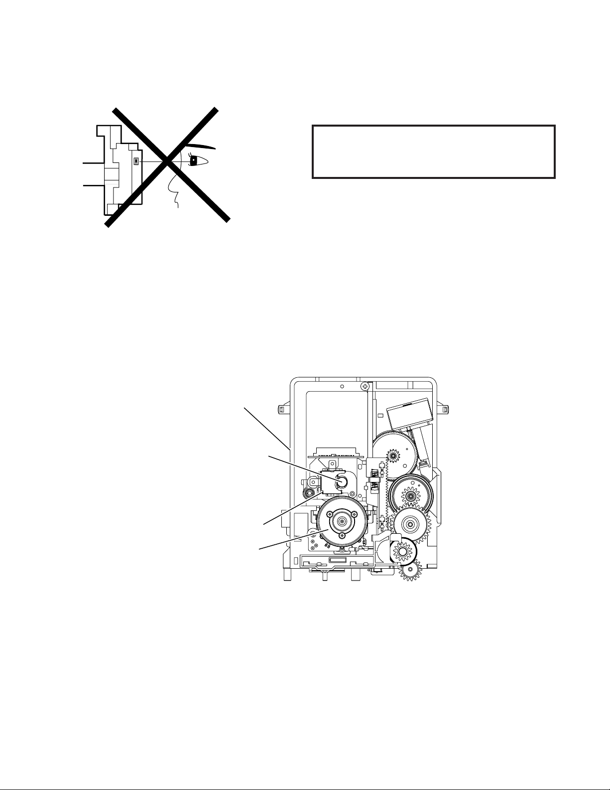
This DVD player uses a pickup that emits a laser beam.
Do not look directly at the laser beam coming
from the pickup or allow it to strike against
your skin.
The laser beam is emitted from the location shown in the figure. When checking the laser diode, be sure to keep your
eyes at least 30cm away from the pickup lens when the diode is turned on. Do not look directly at the laser beam.
Caution: Use of controls and adjustments, or doing procedures other than those specified herein, may result in
hazardous radiation exposure.
rive Mecha Assembly
Laser Beam Radiation
Laser Pickup
Turntable
1-2-1
DVD_LASER
IMPORTANT SAFEGUARDS AND PRECAUTIONS
T
M
T
M
1. IMPORTANT SERVICE NOTES
BEFORE RETURNING THE DVD VIDEO PLAYER
Before returning the DVD video player to the user,
perform the following safety checks.
1. Inspect all lead dress to make certain that leads are
not pinched or that hardware is not lodged between
the chassis and other metal parts in the DVD video
player.
2. Inspect all protective devices such as non-metallic
control knobs, insulation materials, cabinet backs,
adjustment and compartment covers or shields, isolation resistor/capacitor networks, mechanical insulators etc.
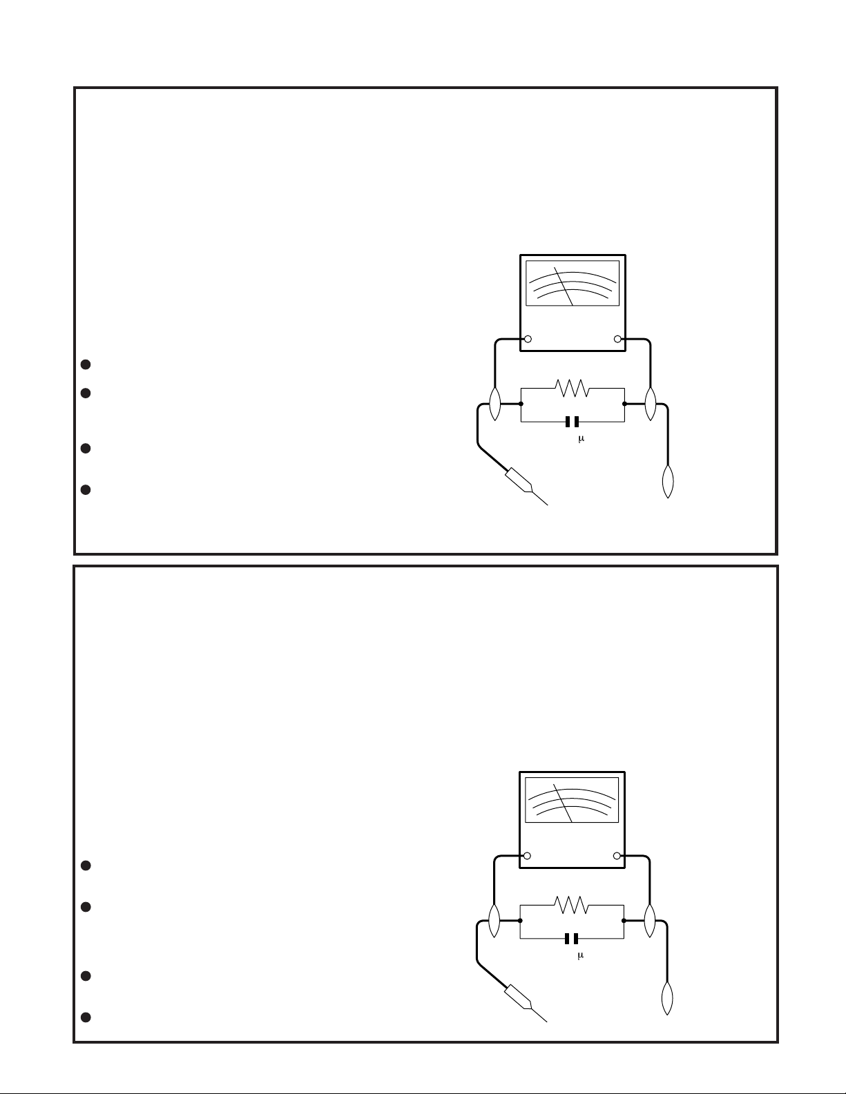
3. To be sure that no shock hazard exists, check for
current in the following manner.
Plug the AC line cord directly into a 230 volt AC outlet
(Do not use an isolation transformer for this test).
Using two clip leads, connect a 1.5k ohm, 10 watt
resistor paralleled by a 0.15µF capacitor in series with
all exposed metal cabinet parts and a known earth
ground, such as a water pipe or conduit.
Use an DVM or VOM with 1000 ohm per volt, or higher,
sensitivity or measure the AC voltage drop across the
resistor (See Diagram).
Move the resistor connection to earth exposed metal
part having a return path to the chassis (metal cabinet,
screw heads, knobs and control shafts, etc.) and
measure the AC voltage drop across the resistor.
Reverse the AC plug on the set and repeat AC voltage
measurements for each exposed part. Any reading of
1.4V rms (this corresponds to 0.7mA rms AC.) or more
is excessive and indicates a potential shock hazard
which must be corrected before returning the DVD
video player to the owner.
SSVM
AC SCALE
2k ohms.
10W
F
0.15
TEST PROBE
O EXPOSED
ETAL PARTS
CONNECT TO
KNOWN EARTH
GROUNG
1. NOTES DE SERVICE IMPORTANTES
AVANT DE RENDRE LE REPRODUCTOR DE VíDEO
DVD
Avant de rendre le reproductor de vídeo DVD à l’utilisateur,
effectuer les vérifications de sécurité suivantes.
1. Vérifier toutes les gaines de fil pour être sûr que les fils
ne sont pas pincés ou que le matériel n’est pas coincé
entre le châssis et les autres pièces métalliques dans le
reproductor de vídeo DVD.
2. Vérifier tous les dispositifs de protection tels que les
boutons de commande non métalliques, les matériaux
d’isolement, le dos du coffret, les couvercles de
compartiment et ajustement ou les boucliers, les
réseaux de résistance / condensateur d’isolement, Ies
isolateurs mécaniques, etc.
3. Pour être sûr qu’il n’y a aucun risque de choc électrique,
vérifier le courant de fuite de la maniére suivante.
Brancher le cordon d’alimentation secteur directement
dans une prise de courant de 230 volts. (Ne pas utiliser
de transformateur d’isolement pour cet essai).
Utiliser deux fils à pinces et connecter une résistance
de 10 watts 1,5 kohm en parallèle avec un condensateur
de 0,15 µF en série avec des pièces du coffret métallique
exposées et une masse de terre connue telle qu’un
tuyau ou un conduit d’eau.
Utiliser un DVM ou VOM avec une sensibilité de 1000
ohms par volt ou plus ou mesurer la chute de tension
CA entre la résistance (voir diagramme).
Déposer la connexion de la résistance à toutes les
pièces métalliques exposées ayant un parcours de
retour au châssis (coffret métallique, tétes de vis, boutons et arbres de commande, etc.) et mesurer la chute
de tension CA entre la résistance. Inverser la fiche CA
(une fiche intermédiaire non polarisée doit être utilisée
à seule fin de faire ces vérifications.) sur l’appareil et
répéter les mesures de tension CA pour chaque piéce
métallique exposée. Toute lecture de 1,4 V rms (ceci
correspond à 0,7 mA rms CA) ou plus est excessive et
signale un danger de choc qui doit être corrigé avant de
rendre le reproductor de vídeo DVD à son utilisateur.
SSVM
AC SCALE
2k ohms.
10W
F
0.15
TEST PROBE
O EXPOSED
ETAL PARTS
CONNECT TO
KNOWN EARTH
GROUNG
1-3-1
E5752IMP
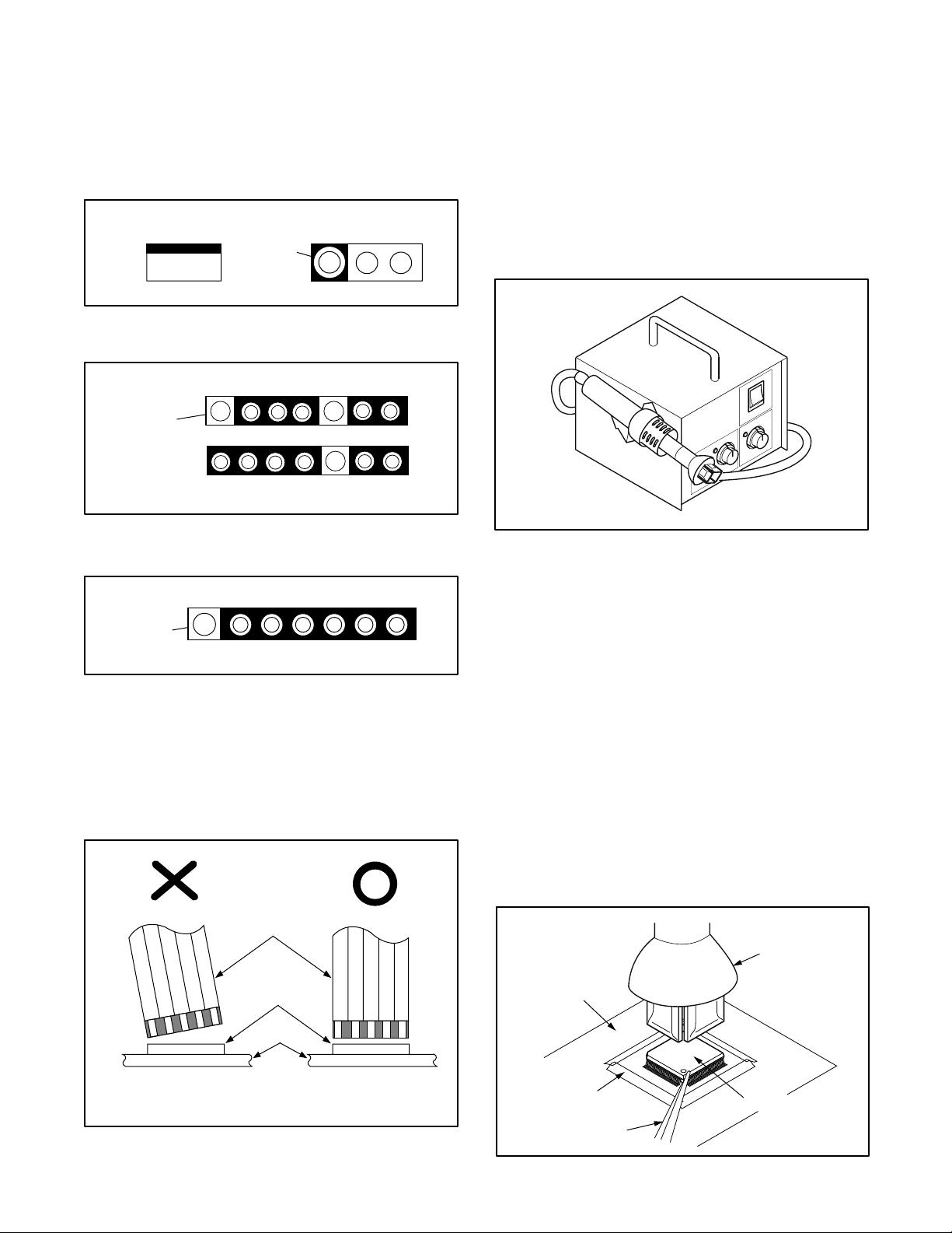
Hot-air
Flat Pack-IC
Desoldering
Machine
CBA
Flat Pack-IC
Tweezers
Masking
Tape
Fig. S-1-2
STANDARD NOTES FOR SERVICING
Circuit Board Indications
a. The output pin of the 3 pin Regulator ICs is indicated
as shown.
Top View
Out
b. For other ICs, pin 1 and every fifth pin are indicated
as shown.
Input
In
Bottom View
5
Pin 1
10
c. The 1st pin of every male connector is indicated as
shown.
Pin 1
Instructions for Connectors
1. When you connect or disconnect the FFC (Flexible
Foil Connector) cable, be sure to first disconnect the
AC cord.
2. FFC (Flexible Foil Connector) cable should be inserted parallel into the connector, not at an angle.
How to Remove / Install Flat Pack-IC
1. Removal
With Hot-Air Flat Pack-IC Desoldering Machine:
(1) Prepare the hot-air flat pack-IC desoldering ma-
chine, then apply hot air to the Flat Pack-IC (about 5
to 6 seconds). (Fig. S-1-1)
Fig. S-1-1
(2)Remove the flat pack-IC with tweezers while apply-
ing the hot air.
(3)Bottom of the flat pack-IC is fixed with glue to the
CBA; when removing entire flat pack-IC, first apply
soldering iron to center of the flat pack-IC and heat
up. Then remove (glue will be melted). (Fig. S-1-6)
(4)Release the flat pack-IC from the CBA using twee-
zers. (Fig. S-1-6)
Caution:
1. Do not supply hot air to the chip parts around the flat
pack-IC for over 6 seconds because damage to the
chip parts may occur. Put masking tape around the
flat pack-IC to protect other parts from damage.
(Fig. S-1-2)
2. The flat pack-IC on the CBA is affixed with glue, so
be careful not to break or damage the foil of each pin
or the solder lands under the IC when removing it.
FFC Cable
Connector
CBA
* Be careful to avoid a short circuit.
1-4-1
DVD_NOTE
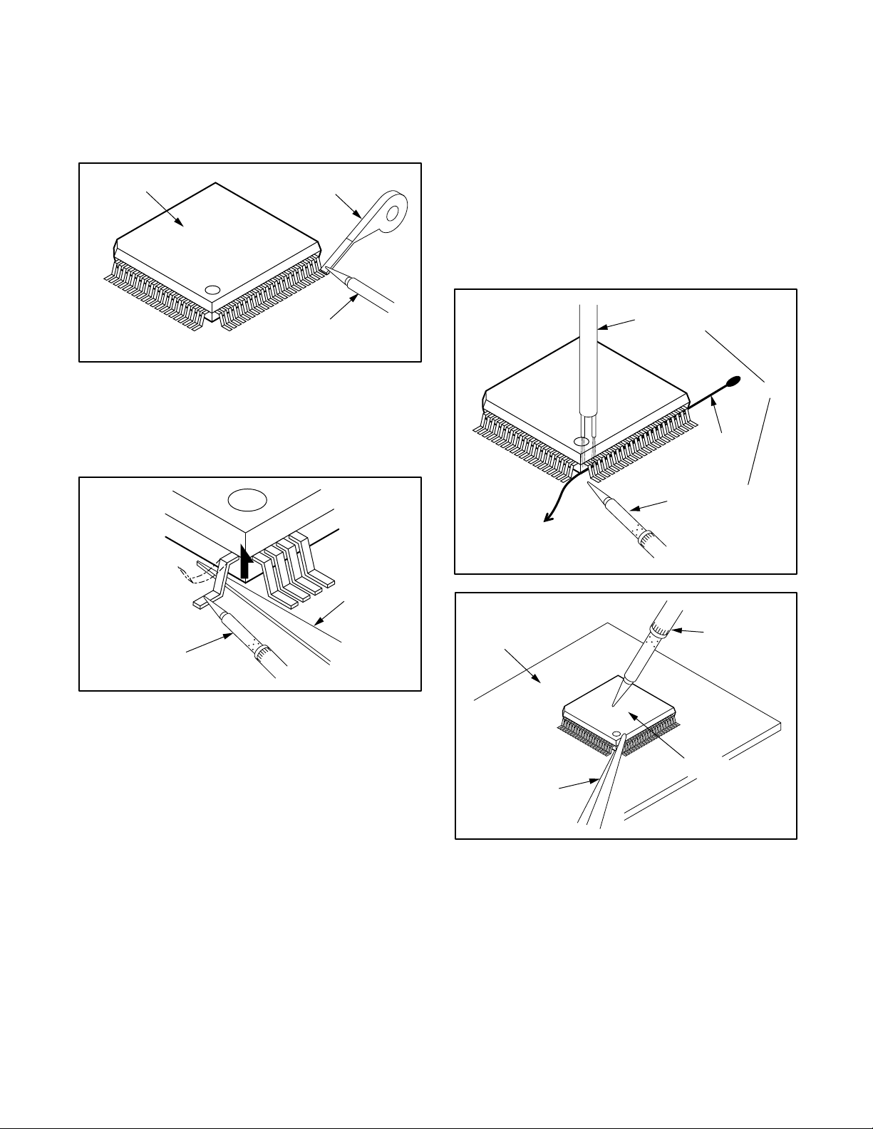
With Soldering Iron:
To Solid
Mounting Point
Soldering Iron
Iron Wire
or
Hot Air Blower
Fig. S-1-5
Fine Tip
Soldeing Iron
CBA
Flat Pack-IC
Tweezers
Fig. S-1-6
(1)Using desoldering braid, remove the solder from all
pins of the flat pack-IC. When you use solder flux
which is applied to all pins of the flat pack-IC, you can
remove it easily. (Fig. S-1-3)
Flat Pack-IC
(2)Lift each lead of the flat pack-IC upward one by one,
using a sharp pin or wire to which solder will not
adhere (iron wire). When heating the pins, use a fine
tip soldering iron or a hot air desoldering machine.
(Fig. S-1-4)
Desoldering Braid
Soldering Iron
Fig. S-1-3
(4)Bottom of the flat pack-IC is fixed with glue to the
CBA; when removing entire flat pack-IC, first apply
soldering iron to center of the flat pack-IC and heat
up. Then remove (glue will be melted). (Fig. S-1-6)
(5)Release the flat pack-IC from the CBA using twee-
zers. (Fig. S-1-6)
Note:
When using a soldering iron, care must be taken to
ensure that the flat pack-IC is not being held by glue.
When the flat pack-IC is removed from the CBA,
handle it gently because it may be damaged if force
is applied.
(3)Bottom of the flat pack-IC is fixed with glue to the
CBA; when removing entire flat pack-IC, first apply
soldering iron to center of the flat pack-IC and heat
up. Then remove (glue will be melted). (Fig. S-1-6)
(4)Release the flat pack-IC from the CBA using twee-
zers. (Fig. S-1-6)
With Iron Wire:
(1)Using desoldering braid, remove the solder from all
pins of the flat pack-IC. When you use solder flux
which is applied to all pins of the flat pack-IC, you can
remove it easily. (Fig. S-1-3)
(2) Affix the wire to a workbench or solid mounting point,
as shown in Fig. S-1-5.
(3)While heating the pins using a fine tip soldering iron
or hot air blower, pull up the wire as the solder melts
so as to lift the IC leads from the CBA contact pads
as shown in Fig. S-1-5.
Fine Tip
Soldering Iron
Sharp
Pin
Fig. S-1-4
1-4-2
DVD_NOTE
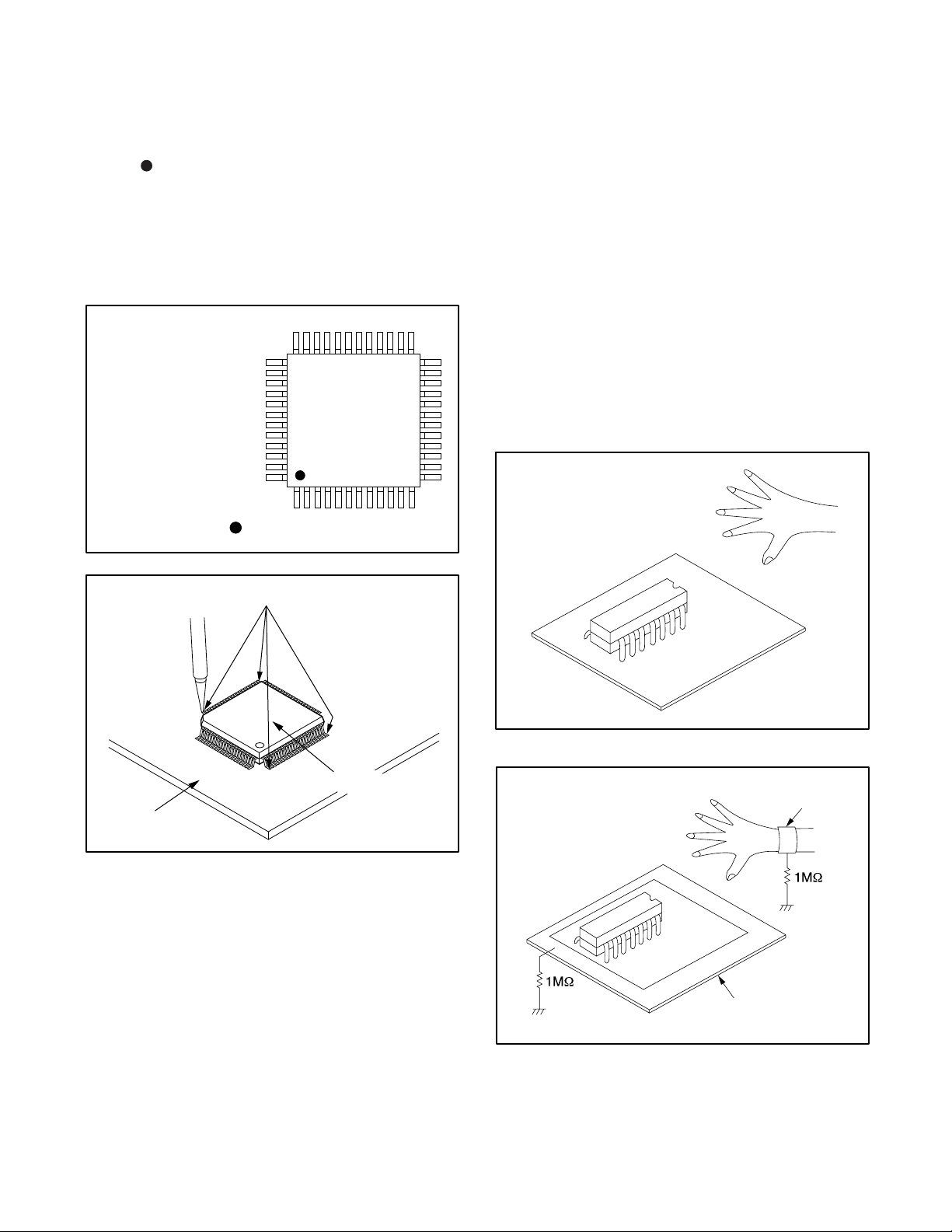
2. Installation
CBA
< Incorrect >
CBA
Grounding Band
Conductive Sheet or
Copper Plate
< Correct >
(1)Using desoldering braid, remove the solder from the
foil of each pin of the flat pack-IC on the CBA so you
can install a replacement flat pack-IC more easily.
(2) The “
(3)Solder all pins of the flat pack-IC. Be sure that none
” mark on the flat pack-IC indicates pin 1. (See
Fig. S-1-7.) Be sure this mark matches the 1 on the
PCB when positioning for installation. Then presolder the four corners of the flat pack-IC. (See Fig. S1-8.)
of the pins have solder bridges.
Instructions for Handling
Semi-conductors
Electrostatic breakdown of the semi-conductors may
occur due to a potential difference caused by electrostatic
charge during unpacking or repair work.
1. Ground for Human Body
Be sure to wear a grounding band (1MΩ) that is properly
grounded to remove any static electricity that may be
charged on the body.
2. Ground for Workbench
Example :
Pin 1 of the Flat Pack-IC
is indicated by a " " mark.
Presolder
Be sure to place a conductive sheet or copper plate with
proper grounding (1MΩ) on the workbench or other
surface, where the semi-conductors are to be placed.
Because the static electricity charge on clothing will not
escape through the body grounding band, be careful to
avoid contacting semi-conductors with your clothing.
Fig. S-1-7
CBA
Flat Pack-IC
Fig. S-1-8
1-4-3
DVD_NOTE
OPERATING CONTROLS AND FUNCTIONS
t
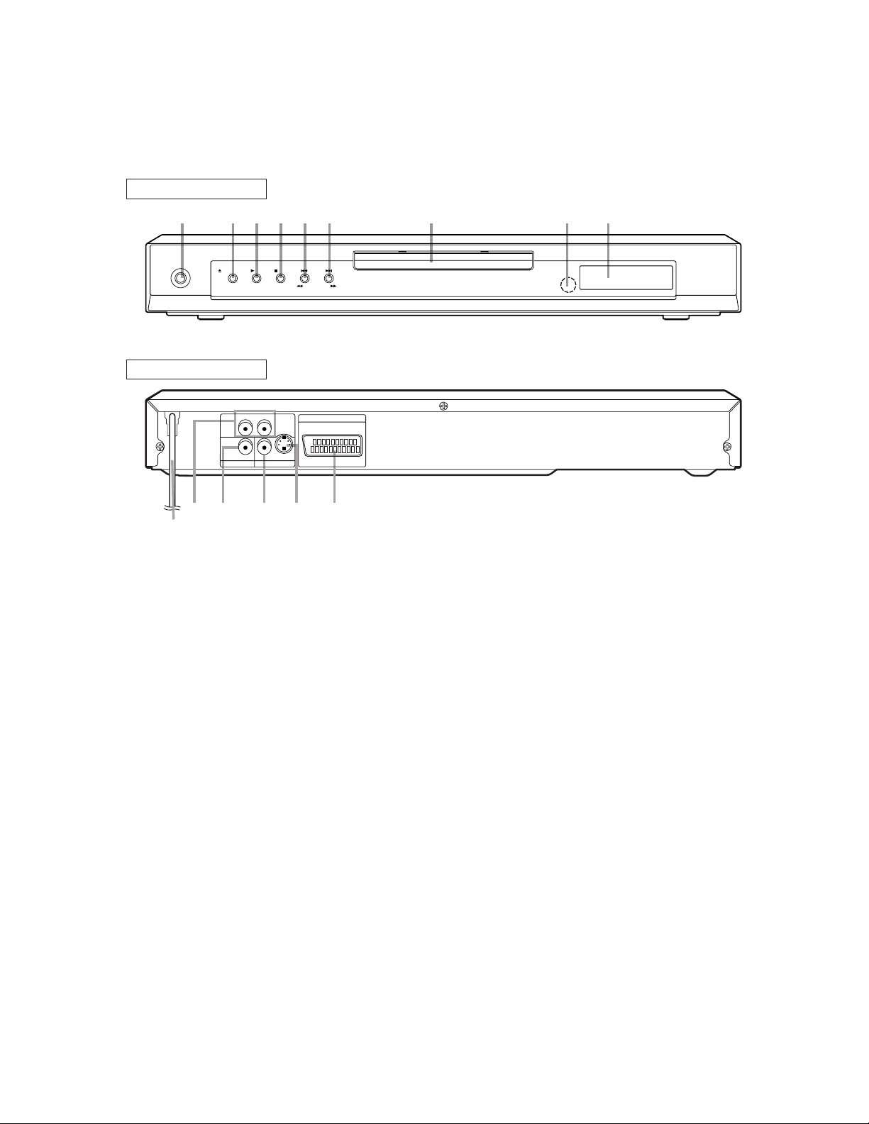
[ DV -SL10H ]
FRONT PANEL
243519876
OPERATE
OPEN/CLOSE PLAY STOP SKIP
REW FWD
REAR VIEW
RL
AUDIO OUT VIDEO OUT
12
13 14 1511
S-VIDEOVIDEODIGITAL
AV (TV)
10
1. OPERATE
to switch the player to ON or OFF
2. OPEN/CLOSE
to open/close the disc tray
3. PLAY
to start or resume disc playback
4. STOP
to stop playback
5. SKIP H / SEARCH h
goes to previous chapter or track during playback; press
and hold for 1.5 seconds for a reverse search
6. SKIP G / SEARCH g
goes to next chapter or track during playback; press and
hold for 1.5 seconds for a forward search
7. Disc tray
8. Remote sensor window
9. Display
10. MAIN (AC Power Cord)
connect to a standard AC outlet
11. AUDIO OUT (Left/Right)
connect to AUDIO inputs of an amplifier, receiver or
stereo system
12. DIGITAL (Digital audio out)
connect to AUDIO inputs of a digital (coaxial) audio
equipment
13. VIDEO OUT
connect to the Video Input of a TV
14. S-VIDEO OUT
connect to a TV with S-Video inputs
15. AV (TV)
connect SCART cable to a TV
Caution: Do not touch the inner pins of the jacks on the
rear
panel. Electrostatic discharge may cause permanen
damage to the player.
1-5-1
E5752IB
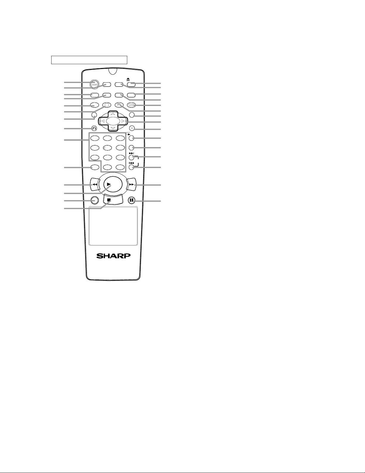
REMOTE CONTROL
s.
k
e
n
.
or
or
1
OPERATE
2
3
4
5
6
7
DIMMER
ZOOM
TITLE
RETURN
8
9
10
CLEAR
11
12
13
14
ON
SCREEN
GAMMA
SUBTITLE
1 2 3
54
7
8 9
C 0
REV
PLAY
STOP
SETUP
MARKER
MODE
ANGLE AUDIO
MENU
ENTER
A-B REPEAT
6
+
10
FWD
STILL/PAUSEDIRECT SKIP
OPEN/
CLOSE
REPEAT
SKIP
15
16
17
18
19
20
21
22
23
24
25
26
27
28
29
1. OPERATE Button
Press to turn the power on and off.
2. ON SCREEN Button
Displays the current status on the TV screen for checking purpose
3. DIMMER Button
Press to change the Panel Display settings.
4. GAMMA Button
Press to adjust the black parts of the picture brighter.
5. ZOOM Button
Enlarges part of a DVD-reproduced image.
6. SUBTITLE Button
Press to select a desired subtitle language.
7. TITLE Button
Displays the title menu.
8. RETURN Button
Returns to the previous operation.
9. Numeric Buttons
10. CLEAR Button
Resets a setting.
11. REV Button
Fast reverse playback to a desired point.
12. PLAY Button
Starts playback of the disc contents.
13. DIRECT SKIP Button
Press to locate a desired point.
14. STOP Button
Stops operation of the disc.
15. OPEN/CLOSE Button
Press to insert discs into or remove them from the tray.
16. SETUP Button
Press to enter the setup mode or to change setup items.
17. MARKER Button
Press to call back the Marker display.
18. MODE Button
Activates programme playback or random playbac
mode.(CD/MP3) Activates the 3D sound.(DVD)
19. AUDIO Button
Press to select a desired audio language or sound mode.
20. ANGLE Button
Press to change the camera angle to see the sequenc
being played back from a different angle.
MENU Button
21.
Displays the DVD menus.
22. Arrow Buttons
Use when making settings while watching the display o
a TV screen.
23. ENTER Button
Press to accept a setting.
24. REPEAT Button
Repeats playback of the current disc, title, chapter or track
25. A-B REPEAT Button
Repeats playback of a selected section.
26. SKIP UP Button
Plays back from the beginning of the next chapter
track.
27. SKIP DOWN Button
Plays back from the beginning of the current chapter
track.
28. FWD Button
Fast
forwards playback to a desired point.
29. STILL/PAUSE Button
Pause playback temporarily/frame-by-frame playback.
1-5-2
E5752IB
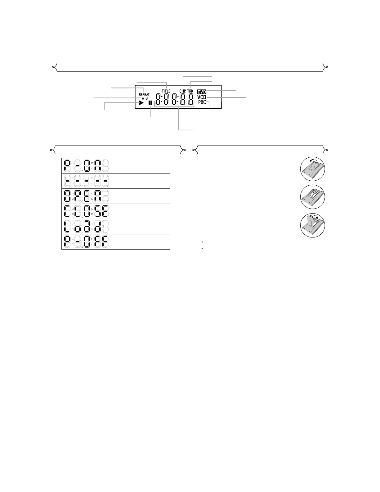
Display
4]
Stays on when
the repeat function is on.
Stays on when
the A-B repeat
function is on.
Stays on when the inserted
disc is being played back.
Stays on when repeat
title function is on.
Lights up when the
inserted disc comes
to a pause.
Stays on when repeat chapter function is on.
Stays on when repeat track function is on.
Lights up when a
playback control is
activated.
Displays how long a current title or track has been
played back. When a chapter or track has switched,
the number of a new title, chapter or track is displayed.
Lights up when a DVD
is inserted on the tray.
CD:
Lights up when a
CD is inserted on
the tray.
VCD:
Lights up when a
Video CD is
inserted on the tray.
[Fig.
Displays During Operation
Power on
No disc inserted or
playing DVD Menu
Tray open
Tray closed
Loading the Disc
Power off
Loading the Batteries
1. Open the battery compartment cover.
2. Insert two AA batteries, with each one
oriented correctly.
3. Close the cover.
NOTES
Do not mix alkaline and manganese batteries.
Do not mix old and new batteries.
1-5-3
E5752IB
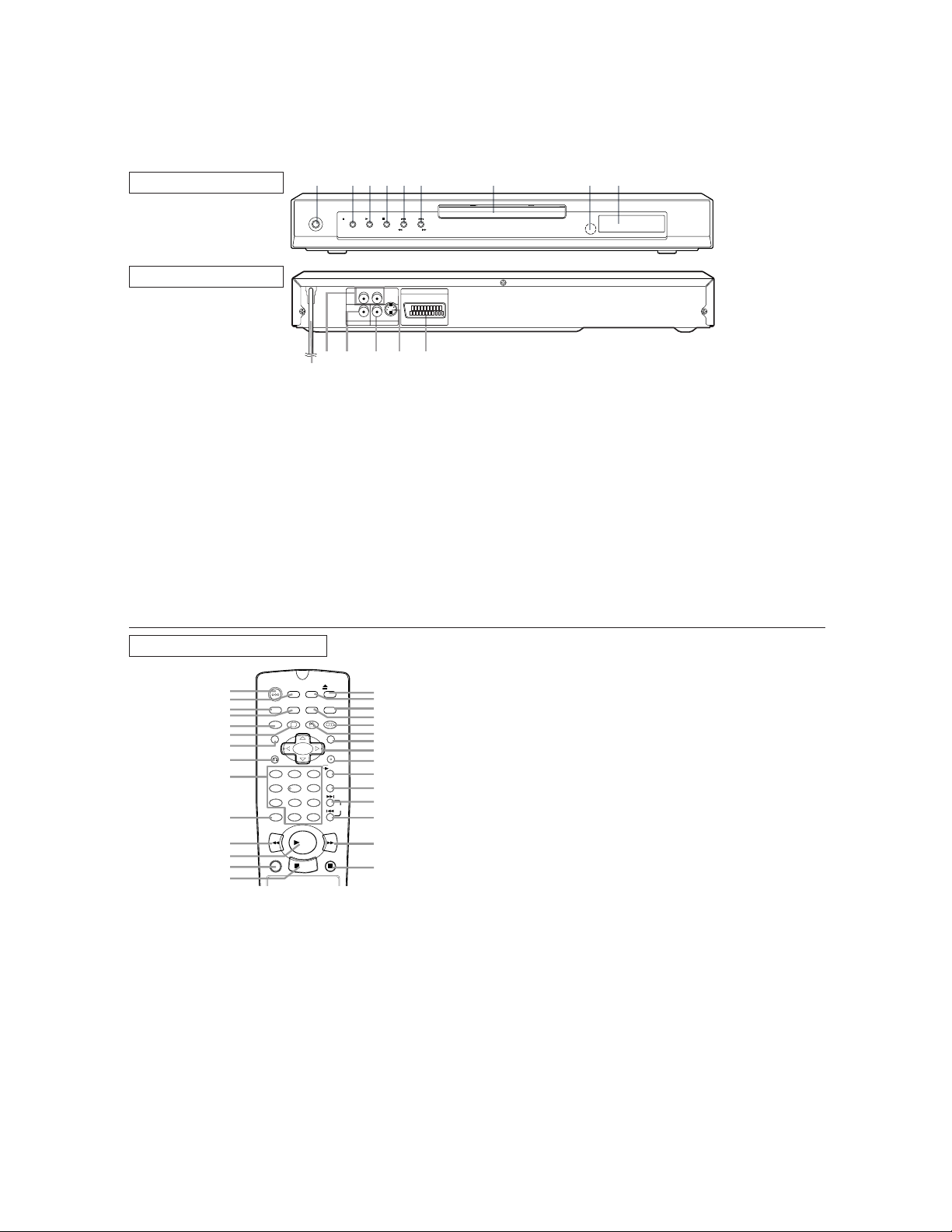
[ DV-SL10S(Y)/DV-SL10S(R) ]
t
k
e
n
.
or
or
1
1
OPERATE
10
243519876
OPEN/CLOSE PLAY STOP SKIP
RL
S-VIDEOVIDEODIGITAL
AUDIO OUT VIDEO OUT
12 13 14 1511
REW FWD
AV (TV)
FRONT PANEL
REAR VIEW
1. OPERATE
to switch the player to ON or OFF
2. OPEN/CLOSE
to open/close the disc tray
3. PLAY
to start or resume disc playback
4. STOP
to stop playback
5. SKIP H / SEARCH h
goes to previous chapter or track during playback; press
and hold for 1.5 seconds for a reverse search
6. SKIP G / SEARCH g
goes to next chapter or track during playback; press and
hold for 1.5 seconds for a forward search
7. Disc tray
8. Remote sensor window
9. Display
10. MAIN (AC Power Cord)
connect to a standard AC outlet
11. AUDIO OUT (Left/Right)
connect to AUDIO inputs of an amplifier, receiver or
stereo system
12. DIGITAL (Digital audio out)
connect to AUDIO inputs of a digital (coaxial) audio
equipment
13. VIDEO OUT
connect to the Video Input of a TV
14. S-VIDEO OUT
connect to a TV with S-Video inputs
15. AV (TV)
connect SCART cable to a TV
Caution: Do not touch the inner pins of the jacks on the
rear panel. Electrostatic discharge may cause permanen
damage to the player.
REMOTE CONTROL
OPEN/
ON
OPERATE
1
2
DIMMER
3
4
5
6
7
8
9
10
ZOOM
TITLE
RETURN
1 2 3
7
CLEAR
C 0
REV
11
12
13
14
1. OPERATE Button
Press to turn the power on and off.
2. ON SCREEN Button
Displays the current status on the TV screen for checking purposes.
3. DIMMER Button
Press to change the Panel Display settings.
4. GAMMA Button
Press to adjust the black parts of the picture brighter.
5. ZOOM Button
Enlarges part of a DVD-reproduced image.
6. SUBTITLE Button
Press to select a desired subtitle language.
7. TITLE Button
Displays the title menu.
8. RETURN Button
Returns to the previous operation.
9. Numeric Buttons
0. CLEAR Button
Resets a setting.
1. REV Button
Fast reverse playback to a desired point.
SCREEN
GAMMA
SUBTITLE
54
8 9
PLAY
STOP
SETUP
MODE
MARKER
ANGLE AUDIO
6
+
10
STILL/PAUSEDIRECT SKIP
CLOSE
MENU
ENTER
REPEAT
A-B REPEAT
FWD
15
16
17
18
19
20
21
22
23
24
25
26
SKIP
27
28
29
12. PLAY Button
Starts playback of the disc contents.
13. DIRECT SKIP Button
Press to locate a desired point.
14. STOP Button
Stops operation of the disc.
15. OPEN/CLOSE Button
Press to insert discs into or remove them from the tray.
16. SETUP Button
Press to enter the setup mode or to change setup items.
17. MARKER Button
Press to call back the Marker display.
18. MODE Button
Activates programme playback or random playbac
mode.(CD/MP3) Activates the 3D sound.(DVD)
19. AUDIO Button
Press to select a desired audio language or sound mode.
20. ANGLE Button
Press to change the camera angle to see the sequenc
being played back from a different angle.
MENU Button
21.
Displays the DVD menus.
22. Arrow Buttons
Use when making settings while watching the display o
a TV screen.
23. ENTER Button
Press to accept a setting.
24. REPEAT Button
Repeats playback of the current disc, title, chapter or track
25. A-B REPEAT Button
Repeats playback of a selected section.
26. SKIP UP Button
Plays back from the beginning of the next chapter
track.
27. SKIP DOWN Button
Plays back from the beginning of the current chapter
track.
28. FWD Button
Fast forwards playback to a desired point.
29. STILL/PAUSE Button
Pause playback temporarily/frame-by-frame playback.
1-5-4
E5752IB
 Loading...