

Page 1
DV-SL10S(G)/DV-SL10W/DV-SL10/DV-SL10X/DV-SL10S(Q)/DV-SL10S(S)/DV-SL10(RU)
SERVICE MANUAL
SERVICE MANUAL
DVD VIDEO PLAYER
DV-SL10S(G)
DVD VIDEO PLAYER
MODELS DV-SL10S(G)/DV-SL10W/DV-SL10/DV-SL10X/DV-SL10S(Q)/DV-SL10S(S)/DV-SL10(RU)
MODELS
In the interests of user-safety (Required by safety regulations in some countries) the set should be restored to its
original condition and only parts identical to those specified
be used.
DV-SL10W
DV-SL10
DV-SL10X
DV-SL10S(Q)
DV-SL10S(S)
DV-SL10(RU)
S63C5DV-SL10S
This service manual supplement (DV -SL10S(G)/DV -SL10W/DV SL10/DV-SL10X/DV-SL10S(Q)/DV-SL10S(S)/DV-SL10(RU))
contains only the difference from the original model.
For all other data, see each original service manual for
DV-SL10H/DV-SL10S(Y)/DV -SL10S(R).
CONTENTS
Page
OPERATING CONTROLS AND FUNCTIONS .................................................................................. 1-1-1
BLOCK DIAGRAMS...........................................................................................................................1-2-1
SCHEMATIC DIAGRAMS/ CBA’S AND TEST POINTS .................................................................... 1-3-1
WAVEFORMS....................................................................................................................................1-4-1
WIRING DIAGRAM ............................................................................................................................ 1-5-1
LEAD IDENTIFICATIONS.................................................................................................................. 1-6-1
EXPLODED VIEWS ........................................................................................................................... 1-7-1
DIFFERENT PARTS FROM ORIGINAL MODEL (DV-SL10H).......................................................... 1-8-1
SHARP CORPORATION
This document has been published to be used for
after sales service only.
The contents are subject to change without notice.
1
Page 2
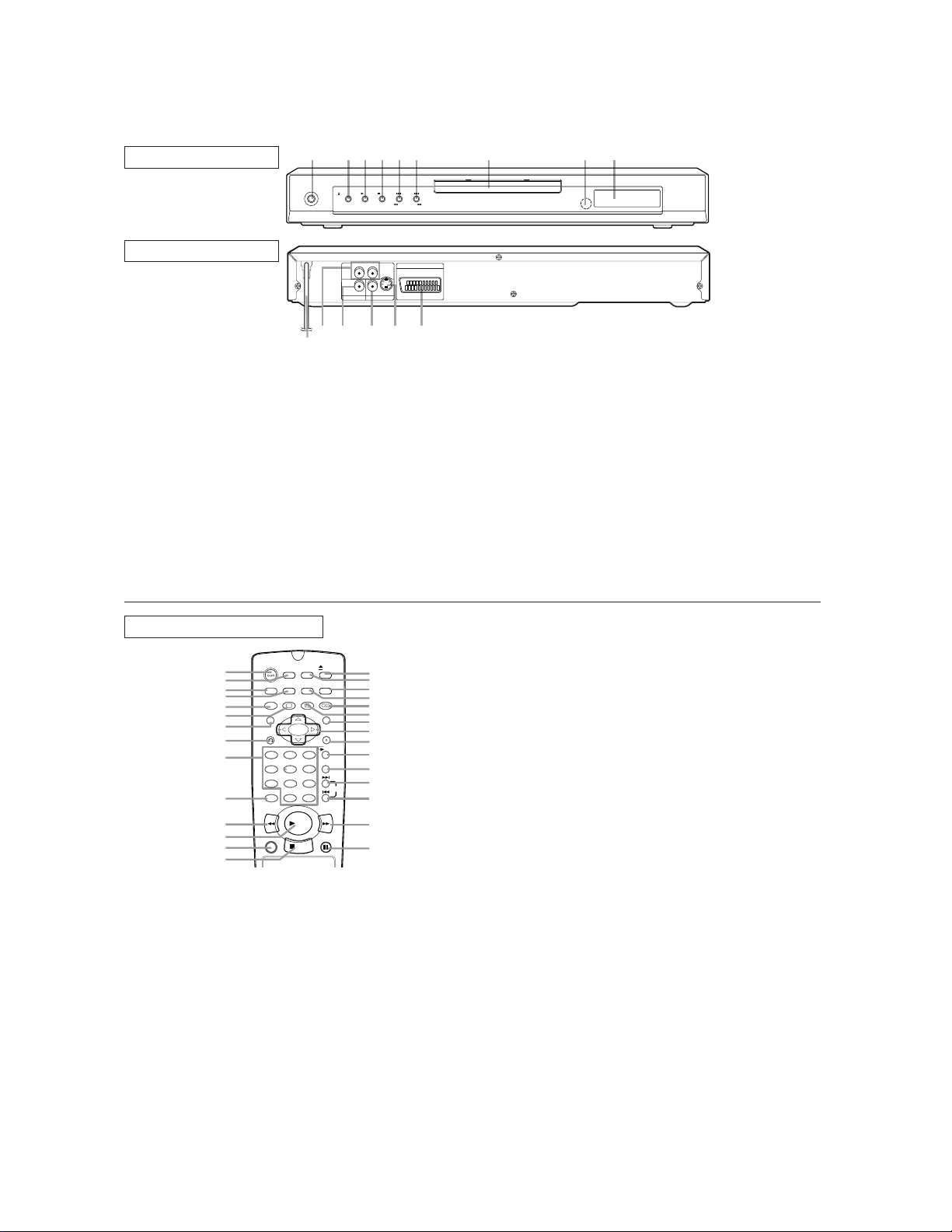
OPERATING CONTROLS AND FUNCTIONS
[ DV -SL10S(G)/DV-SL10S(Q) ]
!"
FRONT PANEL
REAR VIEW
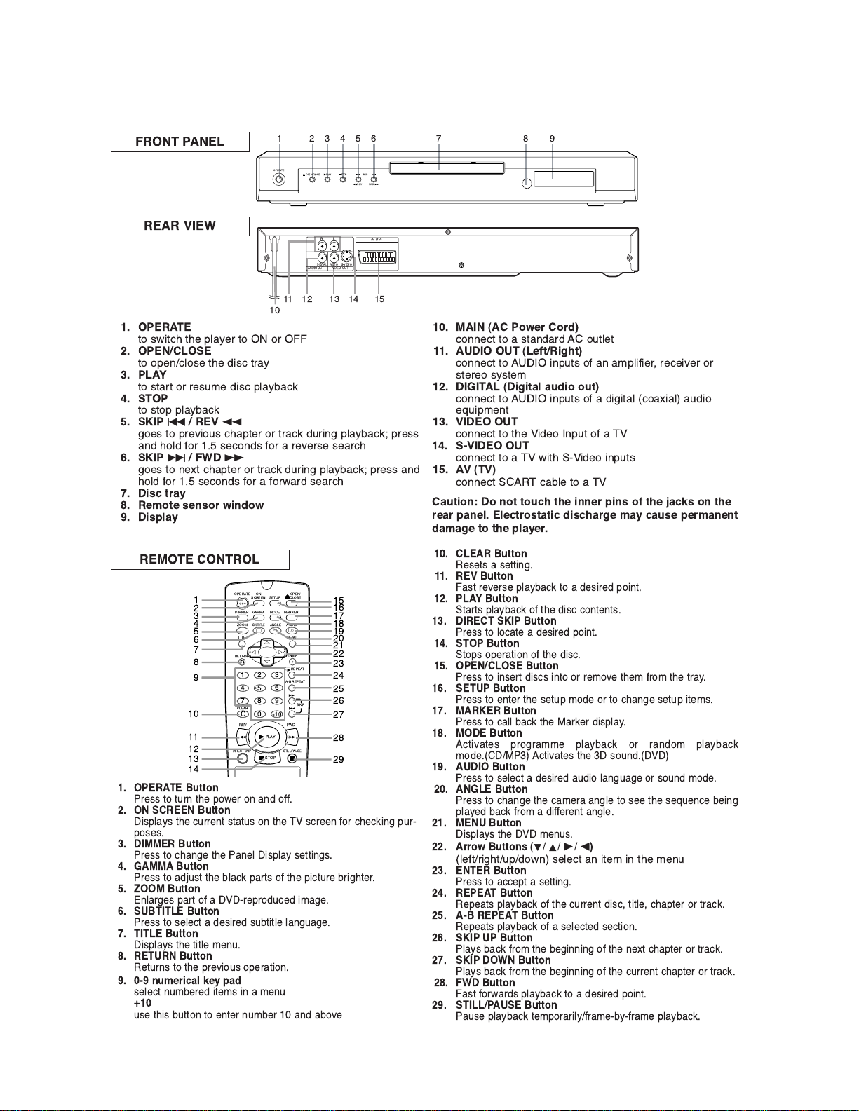
1. OPERATE
'( )*+',- '-. /012.3 '( (3 !!
2. OPEN/CLOSE
'( (/.4,0(). '-. 5+), '312
3. PLAY
'( )'13' (3 3.)67. 5+), /01281,9
4. STOP
'( )'(/ /01281,9
5. SKIPH/ REV
h
:(.) '( /3.;+(6) ,-1/'.3 (3 '31,9 563+4: /01281,9< /3.))
145 -(05 =(3 > ).,(45) =(3 1 3.;.3). ).13,-
6. SKIPG/ FWD
g
:(.) '( 4.?' ,-1/'.3 (3 '31,9 563+4: /01281,9< /3.)) 145
-(05 =(3 > ).,(45) =(3 1 =(3*135 ).13,-
7. Disc tray
8. Remote sensor window
9. Display
10. MAIN (AC Power Cord)
,(44.,' '( 1 )'145135 (6'0.'
11. AUDIO OUT (Left/Right)
,(44.,' '( +4/6') (= 14 17/0+=+.3@ 3.,.+;.3 (3
)'.3.( )2)'.7
12. DIGITAL (Digital audio out)
,(44.,' '( +4/6') (= 1 5+:+'10 ,(1?+10 165+(
.A6+/7.4'
13. VIDEO OUT
,(44.,' '( '-. +5.( 4/6' (= 1
14. S-VIDEO OUT
,(44.,' '( 1 *+'- +5.( +4/6')
15. AV (TV)
,(44.,' ,180. '( 1
Caution: Do not touch the inner pins of the jacks on the
rear panel. Electrostatic discharge may cause permanent
damage to the player.
REMOTE CONTROL
$$
#$
1. OPERATE Button
3.)) '( '634 '-. /(*.3 (4 145 (==>
2. ON SCREEN Button
+)/012) '-. ,633.4' )'1'6) (4 '-. ),3..4 =(3 ,-.,9+4: /63
/().)>
3. DIMMER Button
3.)) '( ,-14:. '-. 14.0 +)/012 ).''+4:)>
4. GAMMA Button
3.)) '( 15B6)' '-. 801,9 /13') (= '-. /+,'63. 83+:-'.3>
5. ZOOM Button
4013:.) /13' (= 1 3./3(56,.5 +71:.>
6. SUBTITLE Button
3.)) '( ).0.,' 1 5.)+3.5 )68'+'0. 014:61:.>
7. TITLE Button
+)/012) '-. '+'0. 7.46>
8. RETURN Button
.'634) '( '-. /3.;+(6) (/.31'+(4>
9. 0-9 numerical key pad
).0.,' 4678.3.5 +'.7) +4 1 7.46
+10
6). '-+) 86''(4 '( .4'.3 4678.3 145 18(;.
$$
%
$
$
%
&
$
!"
10. CLEAR Button
.).') 1 ).''+4:>
11. REV Button
!1)' 3.;.3). /01281,9 '( 1 5.)+3.5 /(+4'>
12. PLAY Button
'13') /01281,9 (= '-. 5+), ,(4'.4')>
13. DIRECT SKIP Button
3.)) '( 0(,1'. 1 5.)+3.5 /(+4'>
14. STOP Button
'(/) (/.31'+(4 (= '-. 5+),>
15. OPEN/CLOSE Button
3.)) '( +4).3' 5+),) +4'( (3 3.7(;. '-.7 =3(7 '-. '312>
16. SETUP Button
3.)) '( .4'.3 '-. ).'6/ 7(5. (3 '( ,-14:. ).'6/ +'.7)>
17. MARKER Button
3.)) '( ,100 81,9 '-. $139.3 5+)/012>
18. MODE Button
,'+;1'.) /3(:3177. /01281,9 (3 3145(7 /01281,9
7(5.>$ ,'+;1'.) '-. )(645>
19. AUDIO Button
3.)) '( ).0.,' 1 5.)+3.5 165+( 014:61:. (3 )(645 7(5.>
20. ANGLE Button
3.)) '( ,-14:. '-. ,17.31 14:0. '( ).. '-. ).A6.4,. 8.+4:
/012.5 81,9 =3(7 1 5+==.3.4' 14:0.>
21. MENU Button
+)/012) '-. 7.46)>
22. Arrow Buttons (L K B s)
0.='3+:-'6/5(*4 ).0.,' 14 +'.7 +4 '-. 7.46
23. ENTER Button
3.)) '( 1,,./' 1 ).''+4:>
24. REPEAT Button
./.1') /01281,9 (= '-. ,633.4' 5+),@ '+'0.@ ,-1/'.3 (3 '31,9>
25. A-B REPEAT Button
./.1') /01281,9 (= 1 ).0.,'.5 ).,'+(4>
26. SKIP UP Button
012) 81,9 =3(7 '-. 8.:+44+4: (= '-. 4.?' ,-1/'.3 (3 '31,9>
27. SKIP DOWN Button
012) 81,9 =3(7 '-. 8.:+44+4: (= '-. ,633.4' ,-1/'.3 (3 '31,9>
28. FWD Button
!1)' =(3*135) /01281,9 '( 1 5.)+3.5 /(+4'>
29. STILL/PAUSE Button
16). /01281,9 '.7/(313+02=317.82=317. /01281,9>
1-1-1
E5753IB
Page 3

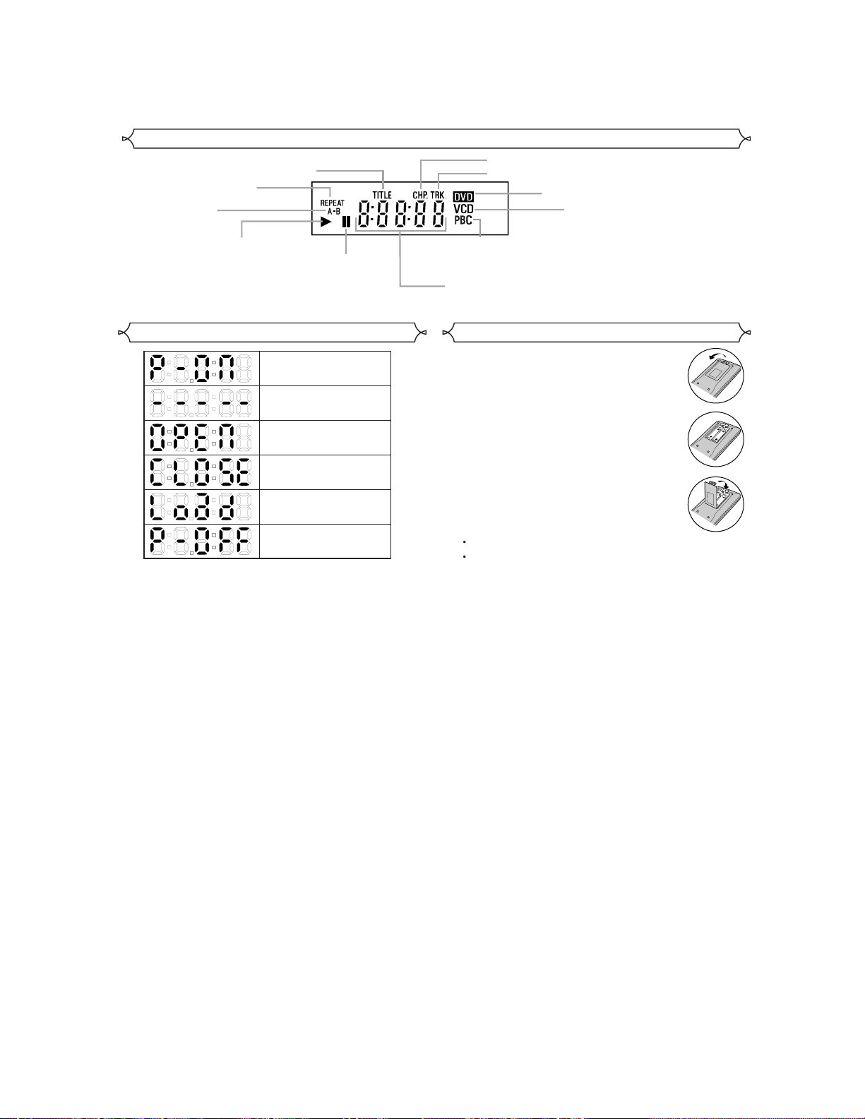
Display
Stays on when
the repeat function is on.
Stays on when
the A-B repeat
function is on.
Stays on when the inserted
disc is being played back.
Stays on when repeat
title function is on.
Lights up when the
inserted disc comes
to a pause.
Stays on when repeat chapter function is on.
Stays on when repeat track function is on.
Lights up when a
playback control is
activated.
Displays how long a current title or track has been
played back. When a chapter or track has switched,
the number of a new title, chapter or track is displayed.
Lights up when a DVD
is inserted on the tray.
CD:
Lights up when a
CD is inserted on
the tray.
VCD:
Lights up when a
Video CD is
inserted on the tray.
Displays During Operation
Power on
No disc inserted or
playing DVD Menu
Tray open
Tray closed
Loading the Disc
Power off
Loading the Batteries
1. Open the battery compartment cover.
2. Insert two AAbatteries, with each one
oriented correctly.
3. Close the cover.
NOTES
Do not mix alkaline and manganese batteries.
Do not mix old and new batteries.
1-1-2
E5753IB
Page 4

[ DV -SL10W ]
t
k
e
.
.
1
OPERATE
243519876
OPEN/CLOSE PLAY STOP SKIP
REV FWD
L
VIDEO
DIGITAL
RC
AUDIO OUT VIDEO OUT
12 1314 151110
CRY
COMPONENT
B
FRONT PANEL
REAR VIEW
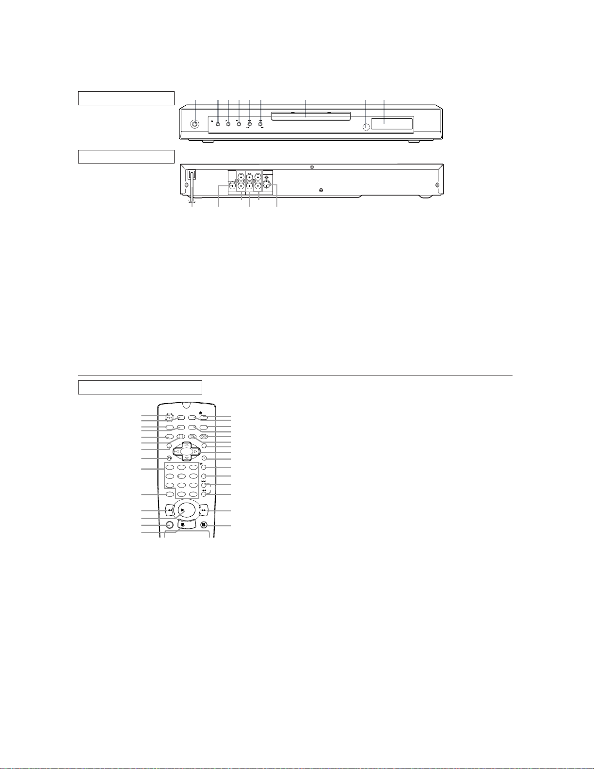
1. OPERATE
to switch the player to ON or OFF
2. OPEN/CLOSE
to open/close the disc tray
3. PLAY
to start or resume disc playback
4. STOP
to stop playback
5. SKIP H / REVh
goes to previous chapter or track during playback; press
and hold for 1.5 seconds for a reverse search
6. SKIP G / FWD g
goes to next chapter or track during playback; press and
hold for 1.5 seconds for a forward search
7. Disc tray
8. Remote sensor window
9. Display
S-VIDEO
10. MAIN (AC Power Cord)
connect to a standard AC outlet
11. DIGITALAUDIO OUT (coaxial)
connect to AUDIO inputs of a digital (coaxial) audio
equipment
12. AUDIO OUT (Left/Right)
connect to AUDIO inputs of an amplifier, receiver or
stereo system
13. VIDEO OUT
connect to the Video Input of a TV
14. COMPONENT VIDEO OUT
connect to a TV with Component video in jacks
15. S-VIDEO OUT
connect to a TV with S-Video inputs
Caution: Do not touch the inner pins of the jacks on the
rear panel. Electrostatic discharge may cause permanen
damage to the player.
REMOTE CONTROL
OPEN/
ON
OPERATE
1
2
DIMMER
3
4
5
6
7
8
9
10
ZOOM
TITLE
RETURN
1 2 3
7
CLEAR
C 0
REV
11
12
13
14
1. OPERATE Button
Press to turn the power on and off.
2. ON SCREEN Button
Displays the current status on the TV screen for checking purposes.
3. DIMMER Button
Press to change the Panel Display settings.
4. GAMMA Button
Press to adjust the black parts of the picture brighter.
5. ZOOM Button
Enlarges part of a DVD-reproduced image.
6. SUBTITLE Button
Press to select a desired subtitle language.
7. TITLE Button
Displays the title menu.
8. RETURN Button
Returns to the previous operation.
9. 0-9 numerical key pad
select numbered items in a menu
+10
use this button to enter number 10 and above
0. CLEAR Button
Resets a setting.
SCREEN
GAMMA
SUBTITLE
54
8 9
PLAY
STOP
SETUP
MODE
MARKER
ANGLE AUDIO
A-B REPEAT
6
+
10
STILL/PAUSEDIRECT SKIP
MENU
ENTER
FWD
CLOSE
REPEAT
15
16
17
18
19
20
21
22
23
24
25
26
SKIP
27
28
29
11. REV Button
Fast reverse playback to a desired point.
12. PLAY Button
Starts playback of the disc contents.
13. DIRECT SKIP Button
Press to locate a desired point.
14. STOP Button
Stops operation of the disc.
15. OPEN/CLOSE Button
Press to insert discs into or remove them from the tray.
16. SETUP Button
Press to enter the setup mode or to change setup items.
17. MARKER Button
Press to call back the Marker display.
18. MODE Button
Activates programme playback or random playbac
mode.(CD/MP3) Activates the 3D sound.(DVD)
19. AUDIO Button
Press to select a desired audio language or sound mode.
20. ANGLE Button
Press to change the camera angle to see the sequenc
being played back from a different angle.
21.
MENU Button
Displays the DVD menus.
22. Arrow Buttons (LKBs)
(left/right/up/down) select an item in the menu
23. ENTER Button
Press to accept a setting.
24. REPEAT Button
Repeats playback of the current disc, title, chapter or track
25. A-B REPEAT Button
Repeats playback of a selected section.
26. SKIP UP Button
Plays back from the beginning of the next chapter or track.
27.
SKIP DOWN Button
Plays back from the beginning of the current chapter or track
28. FWD Button
Fast forwards playback to a desired point.
29. STILL/PAUSE Button
Pause playback temporarily/frame-by-frame playback.
1-1-3
E5753IB
Page 5

Display
Stays on when
the repeat function is on.
Stays on when
the A-B repeat
function is on.
Stays on when the inserted
disc is being played back.
Stays on when repeat
title function is on.
Lights up when the
inserted disc comes
to a pause.
Stays on when repeat chapter function is on.
Stays on when repeat track function is on.
Lights up when a
playback control is
activated.
Displays how long a current title or track has been
played back. When a chapter or track has switched,
the number of a new title, chapter or track is displayed.
Lights up when a DVD
is inserted on the tray.
CD:
Lights up when a
CD is inserted on
the tray.
VCD:
Lights up when a
Video CD is
inserted on the tray.
Displays During Operation
Power on
No disc inserted or
playing DVD Menu
Tray open
Tray closed
Loading the Disc
Power off
Loading the Batteries
1. Open the battery compartment cover.
2. Insert two AAbatteries, with each one
oriented correctly.
3. Close the cover.
NOTES
Do not mix alkaline and manganese batteries.
Do not mix old and new batteries.
1-1-4
E5753IB
Page 6
[ DV-SL10 ]
t
k
e
.
.
1
OPERATE
243519876
OPEN/CLOSE PLAY STOP SKIP
REV FWD
FRONT PANEL
REAR VIEW
CRY
L
VIDEO
DIGITAL
RC
B
AUDIO OUT VIDEO OUT
121314
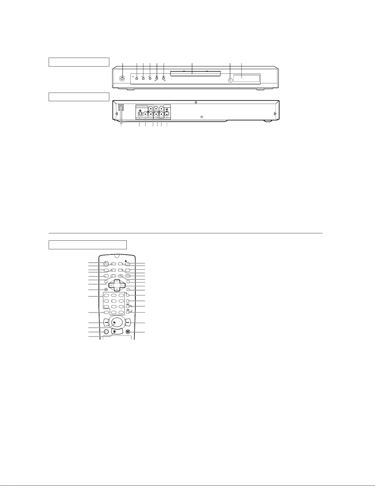
1. OPERATE
to switch the player to ON or OFF
2. OPEN/CLOSE
to open/close the disc tray
3. PLAY
to start or resume disc playback
4. STOP
to stop playback
5. SKIP H / REVh
goes to previous chapter or track during playback; press
and hold for 1.5 seconds for a reverse search
6. SKIP G / FWD g
goes to next chapter or track during playback; press and
hold for 1.5 seconds for a forward search
7. Disc tray
8. Remote sensor window
9. Display
COMPONENT
S-VIDEO
151110
10. MAIN (AC Power Cord)
connect to a standard AC outlet
11. DIGITALAUDIO OUT (coaxial)
connect to AUDIO inputs of a digital (coaxial) audio
equipment
12. AUDIO OUT (Left/Right)
connect to AUDIO inputs of an amplifier, receiver or
stereo system
13. VIDEO OUT
connect to the Video Input of a TV
14. COMPONENT VIDEO OUT
connect to a TV with Component video in jacks
15. S-VIDEO OUT
connect to a TV with S-Video inputs
Caution: Do not touch the inner pins of the jacks on the
rear panel. Electrostatic discharge may cause permanen
damage to the player.
REMOTE CONTROL
OPEN/
ON
OPERATE
1
2
DIMMER
3
4
5
6
7
8
9
10
ZOOM
TITLE
RETURN
1 2 3
7
CLEAR
C 0
REV
11
12
13
14
1. OPERATE Button
Press to turn the power on and off.
2. ON SCREEN Button
Displays the current status on the TV screen for checking purposes.
3. DIMMER Button
Press to change the Panel Display settings.
4. GAMMA Button
Press to adjust the black parts of the picture brighter.
5. ZOOM Button
Enlarges part of a DVD-reproduced image.
6. SUBTITLE Button
Press to select a desired subtitle language.
7. TITLE Button
Displays the title menu.
8. RETURN Button
Returns to the previous operation.
9. 0-9 numerical key pad
select numbered items in a menu
+10
use this button to enter number 10 and above
0. CLEAR Button
Resets a setting.
SCREEN
GAMMA
SUBTITLE
54
8 9
PLAY
STOP
SETUP
MODE
MARKER
ANGLE AUDIO
6
+
10
STILL/PAUSEDIRECT SKIP
CLOSE
MENU
ENTER
REPEAT
A-B REPEAT
FWD
15
16
17
18
19
20
21
22
23
24
25
26
SKIP
27
28
29
11. REV Button
Fast reverse playback to a desired point.
12. PLAY Button
Starts playback of the disc contents.
13. DIRECT SKIP Button
Press to locate a desired point.
14. STOP Button
Stops operation of the disc.
15. OPEN/CLOSE Button
Press to insert discs into or remove them from the tray.
16. SETUP Button
Press to enter the setup mode or to change setup items.
17. MARKER Button
Press to call back the Marker display.
18. MODE Button
Activates programme playback or random playbac
mode.(CD/MP3) Activates the 3D sound.(DVD)
19. AUDIO Button
Press to select a desired audio language or sound mode.
20. ANGLE Button
Press to change the camera angle to see the sequenc
being played back from a different angle.
21.
MENU Button
Displays the DVD menus.
22. Arrow Buttons (LKBs)
(left/right/up/down) select an item in the menu
23. ENTER Button
Press to accept a setting.
24. REPEAT Button
Repeats playback of the current disc, title, chapter or track
25. A-B REPEAT Button
Repeats playback of a selected section.
26. SKIP UP Button
Plays back from the beginning of the next chapter or track.
27.
SKIP DOWN Button
Plays back from the beginning of the current chapter or track
28. FWD Button
Fast forwards playback to a desired point.
29. STILL/PAUSE Button
Pause playback temporarily/frame-by-frame playback.
1-1-5
E5753IB
Page 7

Display
Stays on when
the repeat function is on.
Stays on when
the A-B repeat
function is on.
Stays on when the inserted
disc is being played back.
Stays on when repeat
title function is on.
Lights up when the
inserted disc comes
to a pause.
Stays on when repeat chapter function is on.
Stays on when repeat track function is on.
Lights up when a
playback control is
activated.
Displays how long a current title or track has been
played back. When a chapter or track has switched,
the number of a new title, chapter or track is displayed.
Lights up when a DVD
is inserted on the tray.
CD:
Lights up when a
CD is inserted on
the tray.
VCD:
Lights up when a
Video CD is
inserted on the tray.
Displays During Operation
Power on
No disc inserted or
playing DVD Menu
Tray open
Tray closed
Loading the Disc
Power off
Loading the Batteries
1. Open the battery compartment cover.
2. Insert two AAbatteries, with each one
oriented correctly.
3. Close the cover.
NOTES
Do not mix alkaline and manganese batteries.
Do not mix old and new batteries.
1-1-6
E5753IB
Page 8
[ DV-SL10X ]
1211 1314 1615
t
k
e
.
.
1
OPERATE
243519876
OPEN/CLOSE PLAY STOP SKIP
REV FWD
FRONT PANEL
REAR VIEW
LY
DIGITAL
VIDEO
R
COAXIALOPTICAL
AUDIO OUT VIDEO OUT
1. OPERATE
to switch the player to ON or OFF
2. OPEN/CLOSE
to open/close the disc tray
3. PLAY
to start or resume disc playback
4. STOP
to stop playback
5. SKIP H / REV h
goes to previous chapter or track during playback; press
and hold for 1.5 seconds for a reverse search
6. SKIP G / FWD g
goes to next chapter or track during playback; press and
hold for 1.5 seconds for a forward search
7. Disc tray
8. Remote sensor window
9. Display
10. MAINS (AC Power Cord)
connect to a standard AC outlet
10
C
R
COMPONENT
S-VIDEOC
B
11. OPTICAL (Digital audio out)
connect to digital (optical) audio equipment
12. COAXIAL (Digital audio out)
connect to AUDIO inputs of a digital (coaxial) audio
equipment
13. AUDIO OUT (Left/Right)
connect to AUDIO inputs of an amplifier, receiver or
stereo system
14. VIDEO OUT
connect to the Video Input of a TV
15. COMPONENT VIDEO OUT
connect to a TV with Component video in jacks
16. S-VIDEO OUT
connect to a TV with S-Video inputs
Caution: Do not touch the inner pins of the jacks on the
rear panel. Electrostatic discharge may cause permanen
damage to the player
.
REMOTE CONTROL
OPEN/
ON
OPERATE
1
2
3
4
5
6
7
8
9
10
DIMMER
ZOOM
TITLE
RETURN
1 2 3
7
CLEAR
C 0
REV
11
12
13
14
1. OPERATE Button
Press to turn the power on and off.
2. ON SCREEN Button
Displays the current status on the TV screen for checking purposes.
3. DIMMER Button
Press to change the Panel Display settings.
4. GAMMA Button
Press to adjust the black parts of the picture brighter.
5. ZOOM Button
Enlarges part of a DVD-reproduced image.
6. SUBTITLE Button
Press to select a desired subtitle language.
7. TITLE Button
Displays the title menu.
8. RETURN Button
Returns to the previous operation.
9. 0-9 numerical key pad
select numbered items in a menu
+10
use this button to enter number 10 and above
0. CLEAR Button
Resets a setting.
SCREEN
GAMMA
SUBTITLE
54
8 9
STOP
SETUP
MODE
ANGLE AUDIO
6
+
10
PLAY
CLOSE
MARKER
MENU
ENTER
A-B REPEAT
FWD
STILL/PAUSEDIRECT SKIP
REPEAT
15
16
17
18
19
20
21
22
23
24
25
26
SKIP
27
28
29
11. REV Button
Fast reverse playback to a desired point.
12. PLAY Button
Starts playback of the disc contents.
13. DIRECT SKIP Button
Press to locate a desired point.
14. STOP Button
Stops operation of the disc.
15. OPEN/CLOSE Button
Press to insert discs into or remove them from the tray.
16. SETUP Button
Press to enter the setup mode or to change setup items.
17. MARKER Button
Press to call back the Marker display.
18. MODE Button
Activates programme playback or random playbac
mode.(CD/MP3) Activates the 3D sound.(DVD)
19. AUDIO Button
Press to select a desired audio language or sound mode.
20. ANGLE Button
Press to change the camera angle to see the sequenc
being played back from a different angle.
21.
MENU Button
Displays the DVD menus.
22. Arrow Buttons (LKBs)
(left/right/up/down) select an item in the menu
23. ENTER Button
Press to accept a setting.
24. REPEAT Button
Repeats playback of the current disc, title, chapter or track
25. A-B REPEAT Button
Repeats playback of a selected section.
26. SKIP UP Button
Plays back from the beginning of the next chapter or track.
27.
SKIP DOWN Button
Plays back from the beginning of the current chapter or track
28. FWD Button
Fast forwards playback to a desired point.
29. STILL/PAUSE Button
Pause playback temporarily/frame-by-frame playback.
1-1-7
E5753IB
Page 9

Display
Stays on when
the repeat function is on.
Stays on when
the A-B repeat
function is on.
Stays on when the inserted
disc is being played back.
Stays on when repeat
title function is on.
Lights up when the
inserted disc comes
to a pause.
Stays on when repeat chapter function is on.
Stays on when repeat track function is on.
Lights up when a
playback control is
activated.
Displays how long a current title or track has been
played back. When a chapter or track has switched,
the number of a new title, chapter or track is displayed.
Lights up when a DVD
is inserted on the tray.
CD:
Lights up when a
CD is inserted on
the tray.
VCD:
Lights up when a
Video CD is
inserted on the tray.
Displays During Operation
Power on
No disc inserted or
playing DVD Menu
Tray open
Tray closed
Loading the Disc
Power off
Loading the Batteries
1. Open the battery compartment cover.
2. Insert two AAbatteries, with each one
oriented correctly.
3. Close the cover.
NOTES
Do not mix alkaline and manganese batteries.
Do not mix old and new batteries.
1-1-8
E5753IB
Page 10
[ DV -SL10S(S) ]
t
k
e
.
.
1
OPERATE
10
243519876
OPEN/CLOSE PLAY STOP SKIP
RL
S-VIDEOVIDEODIGITAL
AUDIO OUT VIDEO OUT
12 13 14 1511
REV FWD
AV (TV)
FRONT PANEL
REAR VIEW
1. OPERATE
to switch the player to ON or OFF
2. OPEN/CLOSE
to open/close the disc tray
3. PLAY
to start or resume disc playback
4. STOP
to stop playback
5. SKIP H / REV h
goes to previous chapter or track during playback; press
and hold for 1.5 seconds for a reverse search
6. SKIP G / FWD g
goes to next chapter or track during playback; press and
hold for 1.5 seconds for a forward search
7. Disc tray
8. Remote sensor window
9. Display
10. MAIN (AC Power Cord)
connect to a standard AC outlet
11. AUDIO OUT (Left/Right)
connect to AUDIO inputs of an amplifier, receiver or
stereo system
12. DIGITAL (Digital audio out)
connect to AUDIO inputs of a digital (coaxial) audio
equipment
13. VIDEO OUT
connect to the Video Input of a TV
14. S-VIDEO OUT
connect to a TV with S-Video inputs
15. AV (TV)
connect SCART cable to a TV
Caution: Do not touch the inner pins of the jacks on the
rear panel. Electrostatic discharge may cause permanen
damage to the player
.
REMOTE CONTROL
OPEN/
ON
OPERATE
1
2
DIMMER
3
4
5
6
7
8
9
10
ZOOM
TITLE
RETURN
1 2 3
7
CLEAR
C 0
REV
11
12
13
14
1. OPERATE Button
Press to turn the power on and off.
2. ON SCREEN Button
Displays the current status on the TV screen for checking purposes.
3. DIMMER Button
Press to change the Panel Display settings.
4. GAMMA Button
Press to adjust the black parts of the picture brighter.
5. ZOOM Button
Enlarges part of a DVD-reproduced image.
6. SUBTITLE Button
Press to select a desired subtitle language.
7. TITLE Button
Displays the title menu.
8. RETURN Button
Returns to the previous operation.
9. 0-9 numerical key pad
select numbered items in a menu
+10
use this button to enter number 10 and above
0. CLEAR Button
Resets a setting.
SCREEN
GAMMA
SUBTITLE
54
8 9
PLAY
STOP
SETUP
MODE
MARKER
ANGLE AUDIO
A-B REPEAT
6
+
10
STILL/PAUSEDIRECT SKIP
MENU
ENTER
FWD
CLOSE
REPEAT
15
16
17
18
19
20
21
22
23
24
25
26
SKIP
27
28
29
11. REV Button
Fast reverse playback to a desired point.
12. PLAY Button
Starts playback of the disc contents.
13. DIRECT SKIP Button
Press to locate a desired point.
14. STOP Button
Stops operation of the disc.
15. OPEN/CLOSE Button
Press to insert discs into or remove them from the tray.
16. SETUP Button
Press to enter the setup mode or to change setup items.
17. MARKER Button
Press to call back the Marker display.
18. MODE Button
Activates programme playback or random playbac
mode.(CD/MP3) Activates the 3D sound.(DVD)
19. AUDIO Button
Press to select a desired audio language or sound mode.
20. ANGLE Button
Press to change the camera angle to see the sequenc
being played back from a different angle.
21.
MENU Button
Displays the DVD menus.
22. Arrow Buttons (LKBs)
(left/right/up/down) select an item in the menu
23. ENTER Button
Press to accept a setting.
24. REPEAT Button
Repeats playback of the current disc, title, chapter or track
25. A-B REPEAT Button
Repeats playback of a selected section.
26. SKIP UP Button
Plays back from the beginning of the next chapter or track.
27.
SKIP DOWN Button
Plays back from the beginning of the current chapter or track
28. FWD Button
Fast forwards playback to a desired point.
29. STILL/PAUSE Button
Pause playback temporarily/frame-by-frame playback.
1-1-9
E5753IB
Page 11

Display
Stays on when
the repeat function is on.
Stays on when
the A-B repeat
function is on.
Stays on when the inserted
disc is being played back.
Stays on when repeat
title function is on.
Lights up when the
inserted disc comes
to a pause.
Stays on when repeat chapter function is on.
Stays on when repeat track function is on.
Lights up when a
playback control is
activated.
Displays how long a current title or track has been
played back. When a chapter or track has switched,
the number of a new title, chapter or track is displayed.
Lights up when a DVD
is inserted on the tray.
CD:
Lights up when a
CD is inserted on
the tray.
VCD:
Lights up when a
Video CD is
inserted on the tray.
Displays During Operation
Power on
No disc inserted or
playing DVD Menu
Tray open
Tray closed
Loading the Disc
Power off
Loading the Batteries
1. Open the battery compartment cover.
2. Insert two AAbatteries, with each one
oriented correctly.
3. Close the cover.
NOTES
Do not mix alkaline and manganese batteries.
Do not mix old and new batteries.
1-1-10
E5753IB
Page 12

[ DV -SL10(RU) ]
t
k
e
.
.
1
OPERATE
243519876
OPEN/CLOSE PLAY STOP SKIP
REV FWD
FRONT PANEL
REAR VIEW
CRY
L
VIDEO
DIGITAL
RC
B
AUDIO OUT VIDEO OUT
121314
1. OPERATE
to switch the player to ON or OFF
2. OPEN/CLOSE
to open/close the disc tray
3. PLAY
to start or resume disc playback
4. STOP
to stop playback
5. SKIP H / REV h
goes to previous chapter or track during playback; press
and hold for 1.5 seconds for a reverse search
6. SKIP G / FWD g
goes to next chapter or track during playback; press and
hold for 1.5 seconds for a forward search
7. Disc tray
8. Remote sensor window
9. Display
COMPONENT
S-VIDEO
151110
10. MAIN (AC Power Cord)
connect to a standard AC outlet
11. DIGITAL AUDIO OUT (coaxial)
connect to AUDIO inputs of a digital (coaxial) audio
equipment
12. AUDIO OUT (Left/Right)
connect to AUDIO inputs of an amplifier, receiver or
stereo system
13. VIDEO OUT
connect to the Video Input of a TV
14. COMPONENT VIDEO OUT
connect to a TV with Component video in jacks
15. S-VIDEO OUT
connect to a TV with S-Video inputs
Caution: Do not touch the inner pins of the jacks on the
rear panel. Electrostatic discharge may cause permanen
damage to the player
.
REMOTE CONTROL
OPEN/
ON
OPERATE
1
2
3
4
5
6
7
8
9
10
DIMMER
ZOOM
TITLE
RETURN
1 2 3
7
CLEAR
C 0
REV
11
12
13
14
1. OPERATE Button
Press to turn the power on and off.
2. ON SCREEN Button
Displays the current status on the TV screen for checking purposes.
3. DIMMER Button
Press to change the Panel Display settings.
4. GAMMA Button
Press to adjust the black parts of the picture brighter.
5. ZOOM Button
Enlarges part of a DVD-reproduced image.
6. SUBTITLE Button
Press to select a desired subtitle language.
7. TITLE Button
Displays the title menu.
8. RETURN Button
Returns to the previous operation.
9. 0-9 numerical key pad
select numbered items in a menu
+10
use this button to enter number 10 and above
0. CLEAR Button
Resets a setting.
SCREEN
GAMMA
SUBTITLE
54
8 9
STOP
SETUP
MODE
ANGLE AUDIO
6
+
10
PLAY
CLOSE
MARKER
MENU
ENTER
A-B REPEAT
FWD
STILL/PAUSEDIRECT SKIP
REPEAT
15
16
17
18
19
20
21
22
23
24
25
26
SKIP
27
28
29
11. REV Button
Fast reverse playback to a desired point.
12. PLAY Button
Starts playback of the disc contents.
13. DIRECT SKIP Button
Press to locate a desired point.
14. STOP Button
Stops operation of the disc.
15. OPEN/CLOSE Button
Press to insert discs into or remove them from the tray.
16. SETUP Button
Press to enter the setup mode or to change setup items.
17. MARKER Button
Press to call back the Marker display.
18. MODE Button
Activates programme playback or random playbac
mode.(CD/MP3) Activates the 3D sound.(DVD)
19. AUDIO Button
Press to select a desired audio language or sound mode.
20. ANGLE Button
Press to change the camera angle to see the sequenc
being played back from a different angle.
21.
MENU Button
Displays the DVD menus.
22. Arrow Buttons (LKBs)
(left/right/up/down) select an item in the menu
23. ENTER Button
Press to accept a setting.
24. REPEAT Button
Repeats playback of the current disc, title, chapter or track
25. A-B REPEAT Button
Repeats playback of a selected section.
26. SKIP UP Button
Plays back from the beginning of the next chapter or track.
27.
SKIP DOWN Button
Plays back from the beginning of the current chapter or track
28. FWD Button
Fast forwards playback to a desired point.
29. STILL/PAUSE Button
Pause playback temporarily/frame-by-frame playback.
1-1-11
E5753IB
Page 13
Display
Stays on when
the repeat function is on.
Stays on when
the A-B repeat
function is on.
Stays on when the inserted
disc is being played back.
Stays on when repeat
title function is on.
Lights up when the
inserted disc comes
to a pause.
Stays on when repeat chapter function is on.
Stays on when repeat track function is on.
Lights up when a
playback control is
activated.
Displays how long a current title or track has been
played back. When a chapter or track has switched,
the number of a new title, chapter or track is displayed.
Lights up when a DVD
is inserted on the tray.
CD:
Lights up when a
CD is inserted on
the tray.
VCD:
Lights up when a
Video CD is
inserted on the tray.
Displays During Operation
Power on
No disc inserted or
playing DVD Menu
Tray open
Tray closed
Loading the Disc
Power off
Loading the Batteries
1. Open the battery compartment cover.
2. Insert two AAbatteries, with each one
oriented correctly.
3. Close the cover.
NOTES
Do not mix alkaline and manganese batteries.
Do not mix old and new batteries.
1-1-12
E5753IB
Page 14

BLOCK DIAGRAMS
Digital Signal Process Block Diagram ( DV-SL10W, DV-SL10, DV-SL10X, DV-SL10(RU) )
DATA(AUDIO) SIGNAL
EXTERNAL
MEMORY
I/F
DVD/CD
FORMATTER
ECC
FOCUS SERVO SIGNAL TRACKING SERVO SIGNAL
DECODER
I/F
DMA
BCU
STREAM
I/F
UMAC
IC102 (SDRAM)
DETECTOR
SDRAM
DATA(VIDEO/AUDIO) SIGNAL VIDEO SIGNAL
24
27
60
66
13
31
56
74
85
C 6
D 7
A 8
B 5
F 10
E 2
CD/DVD 9
~~
SDRAM ADDRESS(0-10)
2
~~~
CN201
210
235
2
13
184
205
247
256
124
125
122
123
128
129
126
127
131
130
IC101 (MICRO CONTROLLER)
~
SDRAM ADDRESS(0-10)
~~~
SDRAM DATA(0-31)SDRAM DATA(0-31)
RF
SIGNAL
PROCESS
CIRCUIT
DSP
DECODER
PIXEL
OPERATION
I/O
PROCESSOR
SERIAL
Note:
*
IC103 is not supplied separatery.
Be sure to replace with the DVD Main CBA unit when servicing IC103.
DATA
ROM
INST.
ROM
DATA
ROM
INST.
ROM
DATA
ROM
INST.
ROM
AUDIO
I/F
181
175
176
174
SPDIF
PCM-BCK
PCM-DATA0
PCM-LRCLK
TO VIDEO
/AUDIO
BLOCK
DIAGRAM
FS
TS
PICK-UP
UNIT
CD-LD 12
DVD-LD 14
PD-MONI 13
GND(DVD-PD)
GND(CD-PD)
GND(LD)
FS(+) 18
FS(-) 19
TS(+) 20
TS(-) 17
CN201
15
16
11
CN201
Q253,Q254
AMP
AMP
Q251,Q252
1 3
CD DVD
4
IC201
(SW)
FS(+)
FS(-)
TS(+)
TS(-)
6
FROM SYSTEM
CONTROL/SERVO
BLOCK DIAGRAM
DVD MAIN CBA UNIT
135
133
132
134
78
INTERRUPT
CONTROLLER
CD/DVD
INST.
ROM
DATA
ROM
TIMER
32BIT
CPU
WATCH DOG
TIMER
CPU
I/F
READ
MEMORY
EXADT (0-15), EXADR (16-19)
CPU
I/F
DEBUG
EXADT (0-15), EXADR (16-19)
EXADT (0-7)
EXADT (8-15)
BCU
GENERAL
I/O
INTERRUPT
CONTROLLER
TIMER
WATCH DOG
TIMER
INST
CACHE
IC105 (LATCH)
2
~
9
IC104 (LATCH)
2
~
9
32BIT CPU
DATA
CACHE
D TYPE
LATCH
D TYPE
LATCH
VIDEO
I/F
12
~
EXADR (0-7)
19
12
~
EXADR (8-15)
19
NTSC/PAL
ENCODER
Y
D/A
C
D/A
Cr
D/A
Cb
D/A
EXADT (0-15)
EXADR (16-19)
EXADR (0-15)
158
164
161
160
VIDEO-Y
VIDEO-C
VIDEO-Cr
VIDEO-Cb
IC103 (FLASH ROM)
*
29
~
36
38
~
45
FLASH
ROM
1
~
9
16
~
25
48
TO VIDEO
/AUDIO
BLOCK
DIAGRAM
1-2-1 1-2-2
E5754BLD
Page 15

Video / Audio Block Diagram ( DV-SL10W, DV-SL10, DV-SL10X, DV-SL10(RU) )
VIDEO SIGNAL
AUDIO SIGNALDATA(AUDIO) SIGNAL
FROM DIGITAL
SIGNAL PROCESS
BLOCK DIAGRAM
VIDEO-Y
VIDEO-C
VIDEO-Cb
VIDEO-Cr
CN601
5 5VIDEO-Y
7 7VIDEO-C
3 3VIDEO-Cb
1 1VIDEO-Cr
CN1601
WF1
WF2
IC1402 (VIDEO DRIVER)
11
4dB
6
AMP
4dB
2
AMP
4dB
9
AMP
4dB
AMP
LPF DRIVER
LPF DRIVER
LPF DRIVER
LPF DRIVER
2dB
AMP
2dB
AMP
2dB
AMP
2dB
AMP
2dB
AMP
DRIVER
18
21
23
15
13
WF3
JK1404
COMPOSITE
VIDEO OUT
VIDEO-Y
OUT
VIDEO-Cb
OUT
VIDEO-Cr
OUT
Y
3 4
1
2
C
JK1401
S-VIDEO OUT
DV-SL10X
IC1204
FIBER OPTIC
TRANS MODULE
FROM
DIGITAL
SIGNAL
PROCESS
BLOCK
DIAGRAM
FROM/TO
SYSTEM
CONTROL
/SERVO
BLOCK
DIAGRAM
SPDIF
PCM-BCK
PCM-DATA0
PCM-LRCLK
ADAC-MD
ADAC-MC
ADAC-ML
PCM-SCLK
A-MUTE
IC601 (AUDIO DAC)
1
2
3
13
14
15
SERIAL
PORT
SERIAL
CONTROL
4X/8X
OVERSAMPLING
DIGITAL FILTER
/FUNCTION
CONTROLLER
DVD MAIN CBA UNIT
ENHANCED
MULTI-LEVEL
DELTA-SIGMA
MODULATOR
ZERO DETECT
SYSTEM CLOCK
16
DAC
DAC
LPF+AMP
LPF+AMP
L-CH
R-CH
12
11
JK1202
DIGITAL
AUDIO OUT
JK1404
AUDIO-L
OUT
AUDIO-R
OUT
Q1201
WF4
WF5
Q1351
AMP
+5V
Q1204
+3.3V
IC1201
3
2
6
5
(AMP)
1
7
Q1202
Q1203
7
8
CN601 CN1601
1616SPDIF
11 11AUDIO-L
13 13AUDIO-R
12 12A-L-MUTE
14 14A-R-MUTE
10 10A-MUTE
WF6
AV CBA
+3.3V
1-2-3 1-2-4
E5754BLV
Page 16

Power Supply Block Diagram ( DV-SL10W, DV-SL10, DV-SL10X, DV-SL10(RU) )
CAUTION !
Fixed voltage ( or Auto voltage selectable ) power supply circuit is used in this unit.
If Main Fuse (F1001) is blown, check to see that all components in the power supply
circuit are not defective before you connect the AC plug to the AC power supply.
Otherwise it may cause some components in the power supply circuit to fail.
HOT CIRCUIT. BE CAREFUL.
CAUTION
FOR CONTINUED PROTECTION AGAINST FIRE HAZARD,
REPLACE ONLY WITH THE SAME TYPE FUSE.
NOTE :
The voltage for parts in hot circuit is measured using
hot GND as a common terminal.
AC1001
AC CORD
F1001
T1.6A L 250V
Q1008
LATCH
L1001
LINE
FILTER
D1001, D1002
D1004, D1005
BRIDGE
RECTIFIER
Q1003 Q1001
SWITCHING
CONTROL
SWITCHING
T1001
2
4
7
6
IC1001
ERROR
VOLTAGE DET
11
12
13
14
15
16
17
18
D1003
RECTIFIER
D1006
SCHOTTKY
BARRIER
D1008
SCHOTTKY
BARRIER
D1030
RECTIFIER
D1016
RECTIFIER
Q1005
Q1015
Q1010
Q1011
Q1016
IC1002
+1.5V
REG.
Q1012
Q1002
DV-SL10X
Q1050
J1003
DV-SL10W, DV-SL10,
DV-SL10(RU)
Q1014
Q1004
PWSW
PWRCON
-FL
F1
F2
EV+3.3V
P-ON+12V
EV+5V
P-ON+5V
P-ON+3.3V
CN1001
1,2,3 EV+1.5V
4,5 EV+3.3V
14,15 EV+9V
FROM SYSTEM
CONTROL/SERVO
BLOCK DIAGRAM
FROM/TO
CN401
13 P-ON+5V
17 P-ON+3.3V
HOT
AV CBA
4
3
1
2
(SHUNT REGULATOR)
IC1006
REG
Q1006
E5754BLP1-2-5 1-2-6
Page 17

e
SCHEMATIC DIAGRAMS / CBA’S AND TEST POINTS
(
Standard Notes
WARNING
Many electrical and mechanical parts in this chassis
have special characteristics. These characteristics often
pass unnoticed and the protection afforded by them
cannot necessarily be obtained by using replacement
components rated for higher voltage, wattage, etc.
Replacement parts that have these special safety
characteristics are identified in this manual and its
supplements; electrical components having such
features are identified by the mark " ! " in the schematic
diagram and the parts list. Before replacing any of these
components, read the parts list in this manual carefully.
The use of substitute replacement parts that do not
have the same safety characteristics as specified in the
parts list may create shock, fire, or other hazards.
Capacitor Temperature Markings
Mark
(B)
(F)
(SR)
(Z)
Capacity
change rate
±10%
+30 - 80%
±15%
+30 - 80%
Standard
temperature
20°C
20°C
20°C
20°C
Temperatur
range
-25~+85°C
-25~+85°C
-25~+85°C
-10~+70°C
Notes:
1. Do not use the part number shown on these drawings for ordering. The correct part number is shown
in the parts list, and may be slightly different or
amended since these drawings were prepared.
2. All resistance values are indicated in ohms (K=103,
M=106).
3. Resistor wattages are 1/4W or 1/6W unless otherwise specified.
4. All capacitance values are indicated in µF
(P=10-6 µF).
5. All voltages are DC voltages unless otherwise specified.
6. Electrical parts such as capacitors, connectors, diodes, IC's, transistors, resistors, switches, and fuses
are identified by four digits. The first two digits are
not shown for each component. In each block of the
diagram, there is a note such as shown below to
indicate these abbreviated two digits.
Capacitors and transistors are represented by the
following symbols.
CBA Symbols
(Top View) (Bottom View)
+
Electrolytic Capacitor
Bottom View)
Transistor or Digital Transistor
E C B
(Top View)
E C B
(Top View)
E C B
NPN Transistor
NPN Digital Transistor
(Top View)
E C B
(Top View)
E C B
PNP Transistor
PNP Digital
Transistor
Schematic Diagram Symbols
Digital Transistor
1-3-1
SC-FN2
Page 18

LIST OF CAUTION, NOTES, AND SYMBOLS USED IN THE SCHEMATIC DIAGRAMS ON THE FOLLOWING
1
".
".
3
2
1
PAGES:
1. CAUTION:
FOR CONTINUED PROTECTION AGAINST FIRE HAZARD, REPLACE ONLY WITH THE SAME TYPE FUSE.
2. CAUTION:
Fixed Voltage (or Auto voltage selectable) power supply circuit is used in this unit.
If Main Fuse (F1001) is blown, first check to see that all components in the power supply circuit are not defective
before you connect the AC plug to the AC power supply. Otherwise it may cause some components in the power
supply circuit to fail.
3. Note:
(1)Do not use the part number shown on the drawings for ordering. The correct part number is shown in the parts
list, and may be slightly different or amended since the drawings were prepared.
(2)To maintain original function and reliability of repaired units, use only original replacement parts which are listed
with their part numbers in the parts list section of the service manual.
4. Wire Connectors
(1)Prefix symbol “CN” means “connector” (can disconnect and reconnect).
(2)Prefix symbol “CL” means “wire-solder holes of the PCB” (wire is soldered directly).
5. Voltage indications for PLAY modes on the schematics are as shown below:
Unit: Volts
5.0
231
5.0
PLAY mode
Indicates that the voltage
is not consistent here.
6. How to read converged lines
-D3
Distinction Area
Line Number
(1 to 3 digits)
Examples:
1. "1-D3" means that line number "1" goes to area "D3
2. "1-B1" means that line number "1" goes to area "B1
7. Test Point Information
: Indicates a test point with a jumper wire across a hole in the PCB.
: Used to indicate a test point with a component lead on foil side.
: Used to indicate a test point with no test pin.
AREA D3
1-B1
AREA B1
1-D3
ABCD
: Used to indicate a test point with a test pin.
1-3-2
SC-FN2
Page 19

DVD Main 2/3 Schematic Diagram (DV-SL10W, DV-SL10, DV-SL10X, DV-SL10(RU))
1-3-3
1-3-4 E5754SCD2
Page 20

DVD Main 3/3 Schematic Diagram (DV-SL10W, DV-SL10, DV-SL10X, DV-SL10(RU))
Note:
*
IC103 is not supplied separately.
Be sure to replace with the DVD Main CBA unit when servicing IC103.
DVD MAIN 3/3
Ref No. Positi on
ICS
IC102 O-4
IC103 O-3
IC104 N-3
IC105 N-1
IC451 P-3
IC601 Q-1
CONNECTOR
CN601 R-1
1-3-5 1-3-6
E5754SCD3
Page 21

AV 1/3 Schematic Diagram (DV-SL10W, DV-SL10, DV-SL10X, DV-SL10(RU))
CAUTION !
Fixed voltage ( or Auto voltage selectable ) power supply circuit is used in this unit.
If Main Fuse (F1001) is blown, check to see that all components in the power supply
circuit are not defective before you connect the AC plug to the AC power supply.
Otherwise it may cause some components in the power supply circuit to fail.
CAUTION
FOR CONTINUED PROTECTION AGAINST FIRE HAZARD,
REPLACE ONLY WITH THE SAME TYPE FUSE.
NOTE :
The voltage for parts in hot circuit is measured
using hot GND as a common terminal.
AV 1/3
Ref No. Positi o n
ICS
IC1001 B-1
IC1002 D-4
IC1006 C-1
TRANSISTORS
Q1001 B-3
Q1002 D-3
Q1003 B-2
Q1004 E-3
Q1005 D-2
Q1006 D-1
Q1008 A-1
Q1010 D-2
Q1011 D-1
Q1012 D-2
Q1014 E-3
Q1015 D-2
Q1016 E-2
Q1050 D-3
CONNECTOR
CN1001 F-4
1-3-7 1-3-8
E5754SCAV1
Page 22

AV 2/3 Schematic Diagram (DV-SL10W, DV-SL10, DV-SL10X, DV-SL10(RU))
1-3-9
1-3-10
AV 2/3
Ref No. Positi o n
ICS
IC1201 H-1
IC1402 I-3
TRANSISTORS
Q1201 J-1
Q1202 J-1
Q1203 I -2
Q1204 I -1
Q1351 K-4
Q1352 H-2
CONNECTOR
CN1601 G-3
E5754SCAV2
Page 23

AV 3/3 & Function Schematic Diagram (DV-SL10W, DV-SL10, DV-SL10X, DV-SL10(RU))
7G 6G 5G 4G 3G 2G 1G
a
b
c
d
e
f
g
c
d
e
f
g
c
d
e
f
g
c
d
e
f
g
c
d
e
f
g
c
d
e
f
g
h
i
a
b
a
b
a
b
a
b
a
b
FL2001 MATRIX CHART
STANDBY
TITLE CHP. TRK. CD
V
PBC
DVD
REPEAT
A
-B
1
3
2
4
5
7G 5G 3G 1G4G6G 2G
STANDBY
REPEAT
A-B
TRK.CHP.TITLE
DVD
a
cb
VCD
d
PBC
ef
g
1
2
3
4
5
AV 3/3
Ref No. Positi on
ICS
IC2001 O-3
IC2002 P-2
TRANSISTOR
Q2007 P-2
CONNECTOR
JP2001 P-3
1-3-11 1-3-12
E5754SCAV3
Page 24

AV CBA Top View (DV-SL10W, DV-SL10, DV-SL10X, DV-SL10(RU))
CAUTION !
Fixed voltage ( or Auto voltage selectable ) power supply circuit is used in this unit.
If Main Fuse (F1001) is blown, check to see that all components in the power supply
circuit are not defective before you connect the AC plug to the AC power supply.
Otherwise it may cause some components in the power supply circuit to fail.
CAUTION
FOR CONTINUED PROTECTION AGAINST FIRE HAZARD,
REPLACE ONLY WITH THE SAME TYPE FUSE.
NOTE :
The voltage for parts in hot circuit is measured
using hot GND as a common terminal.
AV CBA
Ref No. Position
ICS
IC1001 C-2
IC1002 B-2
IC1006 C-2
IC1201 D-3
IC1204 E-2
IC1402 E-4
IC2001 A-2
IC2002 C-3
TRANSISTORS
Q1001 C-1
Q1002 B-1
Q1003 D-2
Q1004 B-2
Q1005 A-1
Q1006 A-1
Q1008 D-2
Q1010 A-1
Q1011 A-1
Q1012 A-1
Q1014 B-2
Q1015 A-1
Q1016 A-1
Q1050 B-1
Q1201 E-3
Q1202 E-3
Q1203 E-3
Q1204 E-3
Q1351 E-2
Q1352 D-2
Q2007 C-3
CONNECTORS
CN1001 B-4
CN1601 D-4
JP2001 A-4
1-3-13
1-3-14
BE5716F01011
Page 25

AV CBA Bottom View (DV-SL10W, DV-SL10, DV-SL10X, DV-SL10(RU))
WF3
PIN 21 OF
IC1402
WF1
PIN 5 OF
CN1601
WF2
PIN 7 OF
CN1601
WF4
PIN 11 OF
CN1601
WF5
PIN 13 OF
CN1601
WF6
PIN 16 OF
CN1601
CAUTION !
Fixed voltage ( or Auto voltage selectable ) power supply circuit is used in this unit.
If Main Fuse (F1001) is blown, check to see that all components in the power supply
circuit are not defective before you connect the AC plug to the AC power supply.
Otherwise it may cause some components in the power supply circuit to fail.
CAUTION
FOR CONTINUED PROTECTION AGAINST FIRE HAZARD,
REPLACE ONLY WITH THE SAME TYPE FUSE.
NOTE :
The voltage for parts in hot circuit is measured
using hot GND as a common terminal.
1-3-15
1-3-16
BE5716F01011
Page 26

FUNCTION CBA Top View (DV-SL10W, DV-SL10, DV-SL10X, DV-SL10(RU))
FUNCTION CBA Bottom View (DV-SL10W, DV-SL10, DV-SL10X, DV-SL10(RU))
1-3-17
1-3-18
BE5716F01011
Page 27

WAVEFORMS ( DV-SL10W, DV-SL10, DV-SL10X, DV-SL10(RU) )
WF1
Pin 5 of CN1601
VIDEO-Y 0.2V 20µsec
WF2 Pin 7 of CN1601
WF5
Pin 13 of CN1601
AUDIO-R
WF6
Pin 16 of CN1601
1V 0.5msec
NOTE:
Input
CD: 1kHz PLAY
(WF4~WF6)
DVD: POWER ON (STOP) MODE
(WF1~WF3)
VIDEO-C 0.2V 20µsec
WF3 Pin 21 of IC1402
VIDEO-CVBS 0.5V 20µsec
WF4
Pin 11 of CN1601
SPDIF
1V 0.1µsec
AUDIO-L
1V 0.5msec
1-4-1
1-4-2
E5754WF
Page 28

VIDEO-Y
OUT
VIDEO-Cb
OUT
VIDEO-Cr
OUT
VIDEO
OUT
AUDIO-L
OUT
AUDIO-R
OUT
CN1001
WIRING DIAGRAM ( DV-SL10W, DV-SL10, DV-SL10X, DV-SL10(RU) )
DV-SL10X
DIGITAL
AUDIO OUT
S-VIDEO
OUT
2222
OPTICAL
AUDIO OUT
AV CBA
(BE5716F01011)
AC CORD
CN1601
JP2001 JP2002
K2 1
1
KEY-2 2
2
NU 3
3
NU 4
4
KEY-4 5
5
KEY-3 6
6
KEY-1 7
7
K1 8
8
FUNCTION CBA
(BE5716F01011)
FG
SENSOR
FG CBA
W1001
EV+1.5V 11
EV+1.5V 22
EV+3.3V 44
EV+3.3V 55
GND 66
GND 77
GND 88
GND 99
GND 1010
GND 1111
GND 1212
P-ON+5V 1313
EV+9V 1414
EV+9V 1515
FP-STB 1616
P-ON+3.3V 1717
FP-DIN 1818
EV+1.5V 33
CN401
PWRCON 1919
REMOTE
FP-DOUT 2020
FP-CLK 2121
W1601
AUDIO-L 1111
A-L-MUTE 1212
VIDEO-Cb 33
VIDEO-Y 55
VIDEO-Cr 11
GND 22
GND 66
GND 44
VIDEO-C 77
GND 88
CN601
GND 99
A-MUTE 1010
AUDIO-R 1313
SPDIF 1616
A-R-MUTE 1414
AUDIO+5V 1515
DVD MAIN CBA UNIT
CN201CN301
FG-IN
123
SP(-)7SP(+)
P-ON+3.3V(D)
TRAY-OUT
TRAY-IN
GND
4
5
6
8 SL(-)
9 SL(+)
SLED
MOTOR
M
SPINDLE
MOTOR
M
GND
123456789
VREF
P-ON+5VFE
CBD
A
PD-MONI
GND(LD)
CD/DVD
101112131415161718
DVD-LD
CD-LD
GND(DVD-PD)
TS(+)
FS(-)
FS(+)
TS(-)
GND(CD-PD)
19
20
FS
TS
TRAY-OUT
TRAY-IN
DRIVE CBA
1-5-1
DVD MECHA
11 2 3 5 6 4 7
DETECTOR
PICK UP UNIT
1-5-2
E5754WI
Page 29

LEAD IDENTIFICATIONS
e
E C B
MM1567AJ
34
1
2SA1015-Y (TPE2)
KTA1266 (Y)
KTC3198 (Y)
2SC2120-Y(TPE2)
KTC3205 (Y)
2SC2236-Y-TPE6,C
2SA966(Y)
18
17
PT6313-S-TP
28
1
15
14
E C B
2SC2785 (H)
KTC3199 (GR)
KRA110M
KTA1267 (Y)
BN1L3Z (P)
MM1622XJBE
24
1
2SK3566
G D S
KIA431-AT
13
12
M34506M4-504FP
20
1
11
10
0C-0805T*002
GP1FA513TZ
123
PQ070XF01SZ
1234
1: Vin
2: Vo
3: GND
4: Vc
LTV-817(B,C)-F
A
K
NJM4558D
KIA4558P
8 5
1 4
K A R
C
E
Note:
A: Anode
K: Cathode
E: Emitter
C: Collector
B: Base
R: Referenc
G: Gate
D: Drain
S: Source
1-6-1
E5753LE
Page 30

Cabinet
1
EXPLODED VIEWS
2L011
Comparison Chart of
Models and Marks
Model Mark
DV-SL10S(G)
DV-SL10W
DV-SL10
DV-SL10X
DV-SL10S(Q)
DV-SL10S(S)
DV-SL10(RU)
A
B
C
D
E
F
G
FUNCTION CBA
A2
2L101
2L021
2L105
2L011
DVD Main
CBA Unit
W1001
2L021
W1601
AV CBA
2L031
2L011
2L031
2L031
A16
2L011
[ A,E,F ]
JK1401
2L011
JK1401
JK1404
JK1401
[ D ]
JK1404
JK1202
IC1204
[ B,C,G ]
JK1404
JK1202
JK1402
F1001
2L042
2B11
[ B,C,G ]
2B3
See Electrical Parts List
for parts with this mark.
Some Ref. Numbers are
not in sequence.
A1X
A13
2L021
1B1
A15
A17
A21
[ B,C,G ]
A13
[ D ]
2L071
[ A,E,F ]
[ B,C,D,G ]
AC100
2L041
2B23
1-7-1
E5753EX
Page 31

Packing
[ B,C,D,G ]
X2
X4
X5
X10
Some Ref. Numbers are not in sequence.
S2
X1
S8
S4
Unit
S5
S2
Comparison Chart of
Models and Marks
Model Mark
DV-SL10S(G)
DV-SL10W
DV-SL10
DV-SL10X
DV-SL10S(Q)
DV-SL10S(S)
DV-SL10(RU)
A
B
C
D
E
F
G
S1
1-7-2
A22
A30
E5753EX
Page 32

DIFFERENT PARTS FROM ORIGINAL MODEL (DV-SL10H)
PRODUCT SAFETY NOTE: Products marked with a ! have special characteristics important to safety. Before
replacing any of these components, read carefully the product safety notice in this service manual. Don't degrade
the safety of the product through improper servicing.
NOTES:
1. Parts that not assigned part numbers (---------) are not available.
2. Tolerance of Capacitors and Resistors are noted with the following symbols.
C.....±0.25% D.....±0.5% F.....±1% G.....±2% J......±5% K.....±10%
M.....±20% N.....±30% Z.....+80/-20%
DV-SL10S(G)
Ref. No. Description Part No. Code
A21! LABEL, RATING E5753ED ---------- --A22 LABEL, BAR CODE E5753ED ---------- --A30 CASE MARK LABEL E5753ED ---------- --S1 GIFT BOX CARTON E5753ED 9HS0VM306277 AV
S2 STYROFOAM E57S0UD 9HS0VM101231 AE
X10! OWNER'S MANUAL E5753ED 9HS0VMN03661 AH
X17 Not Used
DV-SL10W
Ref. No. Description Part No. Code
Mechanical Parts
2B23 SHEET, INSULATOR E57S7RD 9HS0VM415311 AE
A17 REAR PANEL E5754HD 9HS0VM204230 AK
A21! LABEL, RATING E5754HD ---------- --A22 LABEL, BAR CODE E5754HD ---------- --A30 CASE MARK LABEL E5754HD ---------- --S1 GIFT BOX CARTON E5754HD 9HS0VM306332 AN
X5 AV CORD 9HSX1E56B5-001 AL
X10! OWNER'S MANUAL E5754HD 9HS0VMN03662 AG
X17 Not used
Electrical Parts
DVD MAIN CBA UNIT 9HSN79SFGHP
CN601 FFC/FPC CONNECTOR, 16P 04 6232 116 103 800 9HSC62D16TM003 AE
CN601 FFC/FPC CONNECTOR, 16P 10008HR-16 9HSCHRD16YEE02 --IC102 IC(SDRM) P2V64S50DTP-75 9HSSZBA0R0M002 AZ
IC102 IC(SDRM) 2X32Y3VTW-6 9HSSZBA0R3S001 AX
L616 CHIP BEAD MMZ1608Y121CT 9HSL06001TE004 --R608 Not Used
AV CBA ASSEMBLY 9HS0VSA14186 BW
AV CBA 9HS0VSA14186A ---
FUNCTION CBA 9HS0VSA14186B ---
AV CBA 9HS0VSA14186A --2B11 HEATSINK E5717QD 9HS0VM415264 AD
2L042 SCREW, S-TIGHT M3X8 BIND + CHROME 9HSGBMS3080 --C1004 ELECTROLYTIC CAP. 100µF/400V M 9HSA2H101NC084 --C1007 ELECTOLYTIC CAP. 1000µF/6.3V M(105C) 9HSE0KMASDH102 ---
C1010 Not used
C1017 Not used
C1035 ELECTROLYTIC CAP. 470µF/16V M(105C) 9HSE1CMASTH471 ---
C1070 Not used
1-8-1
E5753PL
Page 33

Ref. No. Description Part No. Code
C1486 Not used
C1487 Not used
C1491 Not used
C1492 Not used
C1533 CHIP CERAMIC CAP. F Z 0.1µF/50V 9HSHD1JZ30F104 --C1434 Not used
C1435 Not used
CN1601 FMN CONNECTOR, TOP 16P 16FMN-BTK 9HSCFNG16JG001 AD
CN1601 FFC/FPC CONNECTOR, 16P 00 6232 016 000 800 9HSC62G16TM009 --CN2101 Not used
D1070 ZENER DIODE DZ-33BSDT265 9HSDTD00DZ33BS --D1070 ZENER DIODE MTZJT-7733D 9HSDTD00MTZJ33 --D1072 Not used
D1073 SWITCHING DIODE 1N4148M 9HSDTZ01N4148M --D1073 SWITCHING DIODE 1SS133(T-77) 9HSDTZ001SS133 --D1074 Not used
D1075 Not used
D1201 Not used
D1202 Not used
D1203 Not used
D1204 Not used
D1401 Not used
D1402 Not used
D1501 Not used
D1502 Not used
D1503 Not used
D1504 Not used
D1505 Not used
D1506 Not used
D1507 Not used
IC1401 Not used
IC1402 DRIVER FOR DVD MM1622XJBE 9HSSZBA0TMM085 AL
JK1202 RCA JACK(BLACK) MSP-251V-01 NI 9HSXRL010LY070 AC
JK1402 Not used
JK1404 RCA JACK MSD-246V-65NI/PBSN 9HSXRL060LY069 AG
JP2001 PARALLEL WIRE (8P)250MM WX1E57S0-003 9HSX1E57S0-003 AF
L1405 Not used
L1441 CHIP BEAD MMZ1608Y121CT 9HSL06001TE004 --L1461 CHIP BEAD MMZ1608Y121CT 9HSL06001TE004 --L1462 Not used
L1481 CHIP BEAD MMZ1608Y121CT 9HSL06001TE004 --L1482 Not used
L1492 Not used
L1522 CHIP BEAD MMZ1608R102CT 9HSL06001TE002 --L1522A Not used
Q1003 TRANSISTOR KTC3199(BL) 9HSQS50KTC3199 --Q1003 TRANSISTOR 2SC2785(K) 9HSQSK02SC2785 --Q1003 TRANSISTOR 2SC1815-BL(TPE2) 9HSQS202SC1815 --Q1050 Not used
Q1521 Not used
Q1522 Not used
R1005 CARBON RES. 1/4W J 2.7M Ω 9HSCX4JATZ0275 ---
R1006 CARBON RES. 1/4W J 2.7M Ω 9HSCX4JATZ0275 ---
R1008 CARBON RES. 1/4W J 910 Ω 9HSCX4JATZ0911 ---
R1011 METAL OXIDE FILM RES. 1W J 1.8 Ω 9HSN011R8ZU001 ---
R1011 METAL OXIDE FILM RES. 1W J 1.8 Ω 9HSN011R8KE009 ---
R1015 Not used
R1016 Not used
R1023 CHIP RES. 1/16W F 3.9k Ω 9HSRXGFR5Z0392 ---
R1023 CHIP RES.(1608) 1/10W F 3.9k Ω 9HSRXAFR5Z3901 ---
1-8-2
E5753PL
Page 34

Ref. No. Description Part No. Code
R1029 CARBON RES. 1/4W J 470k Ω 9HSCX4JATZ0474 ---
R1034 PCB JUMPER D0.6-P5.0 9HSJW5.0T --R1072 CHIP RES.(1608) 1/10W J 1k Ω 9HSRXAJR5Z0102 ---
R1074 RECTIFIER DIODE 1N4005 9HSDQZ001N4005 --R1096 METAL OXIDE FILM RES. 2W J 150k Ω 9HSN02154ZU001 --R1096 METAL OXIDE FILM RES. 2W J 150k Ω 9HSN02154KE010 ---
R1097 Not used
R1098 Not used
R1256 Not used
R1257 Not used
R1371 CHIP RES.(1608) 1/10W 0 Ω 9HSRXAZR5Z0000 ---
R1405 Not used
R1443 CHIP RES.(1608) 1/10W J 75 Ω 9HSRXAJR5Z0750 ---
R1462 CHIP RES.(1608) 1/10W J 75 Ω 9HSRXAJR5Z0750 ---
R1463 Not used
R1482 CHIP RES.(1608) 1/10W J 75 Ω 9HSRXAJR5Z0750 ---
R1483 Not used
R1491 Not used
R1492 Not used
R1522 Not used
R1523 CHIP BEAD MMZ1608Y121CT 9HSL06001TE004 --R1524 CHIP INDUCTOR BK1608HS121-T 9HSLC121NTU017 --R1525 CHIP INDUCTOR BK1608HS121-T 9HSLC121NTU017 --R1526 Not used
R1530 Not used
R1531 Not used
R1558 Not used
R1613 CHIP RES.(1608) 1/10W J 2.2k Ω 9HSRXAJR5Z0222 ---
R1614 Not used
T1001! POWER TRANSFORMER CSA-SW0308A 9HSTT00ZPSA144 AH
W1601 16P FFC 9HSX1E57S0-001 AF
W2101 Not used
FUNCTION CBA 9HS0VSA14186B --SW2007 PCB JUMPER D0.6-P6.5 9HSJW6.5T ---
DV-SL10
Ref. No. Description Part No. Code
Mechanical Parts
2B23 SHEET, INSULATOR E57S7RD 9HS0VM415311 AE
A17 REAR PANEL E5754HD 9HS0VM204230 AK
A21! LABEL, RATING E5755PD ---------- --A22 LABEL, BAR CODE E5755PD ---------- --A30 CASE MARK LABEL E5755PD ---------- --S1 GIFT BOX CARTON E5755PD 9HS0VM306333 AM
S2 STYROFOAM E57S0UD 9HS0VM101231 AE
X5 AV CORD 9HSX1E56B5-001 AL
X10! OWNER'S MANUAL E5754HD 9HS0VMN03662 AG
X17 Not used
Electrical Parts
DVD MAIN CBA UNIT 9HSN79SFGHP
CN601 FFC/FPC CONNECTOR, 16P 04 6232 116 103 800 9HSC62D16TM003 AE
CN601 FFC/FPC CONNECTOR, 16P 10008HR-16 9HSCHRD16YEE02 --IC102 IC(SDRM) P2V64S50DTP-75 9HSSZBA0R0M002 AZ
IC102 IC(SDRM) 2X32Y3VTW-6 9HSSZBA0R3S001 AX
L616 CHIP BEAD MMZ1608Y121CT 9HSL06001TE004 --R608 Not Used
AV CBA ASSEMBLY 9HS0VSA14189 BW
1-8-3
E5753PL
Page 35

Ref. No. Description Part No. Code
AV CBA 9HS0VSA14189A ---
FUNCTION CBA 9HS0VSA14189B ---
AV CBA 9HS0VSA14189A --AC1001! AC CORD PE8G2CG9G0A-055 9HSAE0162LW001 AG
2B11 HEATSINK E5717QD 9HS0VM415264 AD
2L042 SCREW, S-TIGHT M3X8 BIND + CHROME 9HSGBMS3080 --C1004 ELECTROLYTIC CAP. 100µF/400V M 9HSA2H101NC084 --C1007 ELECTOLYTIC CAP. 1000µF/6.3V M(105C) 9HSE0KMASDH102 ---
C1010 Not used
C1017 Not used
C1035 ELECTROLYTIC CAP. 470µF/16V M(105C) 9HSE1CMASTH471 ---
C1070 Not used
C1486 Not used
C1487 Not used
C1491 Not used
C1492 Not used
C1533 CHIP CERAMIC CAP. F Z 0.1µF/50V 9HSHD1JZ30F104 --C1434 Not used
C1435 Not used
CN1601 FMN CONNECTOR, TOP 16P 16FMN-BTK 9HSCFNG16JG001 AD
CN1601 FFC/FPC CONNECTOR, 16P 00 6232 016 000 800 9HSC62G16TM009 --CN2101 Not used
D1070 ZENER DIODE DZ-33BSDT265 9HSDTD00DZ33BS --D1070 ZENER DIODE MTZJT-7733D 9HSDTD00MTZJ33 --D1072 Not used
D1073 SWITCHING DIODE 1N4148M 9HSDTZ01N4148M --D1073 SWITCHING DIODE 1SS133(T-77) 9HSDTZ001SS133 --D1074 Not used
D1075 Not used
D1201 Not used
D1202 Not used
D1203 Not used
D1204 Not used
D1401 Not used
D1402 Not used
D1501 Not used
D1502 Not used
D1503 Not used
D1504 Not used
D1505 Not used
D1506 Not used
D1507 Not used
IC1401 Not used
IC1402 DRIVER FOR DVD MM1622XJBE 9HSSZBA0TMM085 AL
JK1202 RCA JACK(BLACK) MSP-251V-01 NI 9HSXRL010LY070 AC
JK1402 Not used
JK1404 RCA JACK MSD-246V-65NI/PBSN 9HSXRL060LY069 AG
JP2001 PARALLEL WIRE (8P)250MM WX1E57S0-003 9HSX1E57S0-003 AF
L1405 Not used
L1441 CHIP BEAD MMZ1608Y121CT 9HSL06001TE004 --L1461 CHIP BEAD MMZ1608Y121CT 9HSL06001TE004 --L1462 Not used
L1481 CHIP BEAD MMZ1608Y121CT 9HSL06001TE004 --L1482 Not used
L1492 Not used
L1522 CHIP BEAD MMZ1608R102CT 9HSL06001TE002 --L1522A Not used
Q1003 TRANSISTOR KTC3199(BL) 9HSQS50KTC3199 --Q1003 TRANSISTOR 2SC2785(K) 9HSQSK02SC2785 ---
1-8-4
E5753PL
Page 36

Ref. No. Description Part No. Code
Q1003 TRANSISTOR 2SC1815-BL(TPE2) 9HSQS202SC1815 --Q1050 Not used
Q1521 Not used
Q1522 Not used
R1005 CARBON RES. 1/4W J 2.7M Ω 9HSCX4JATZ0275 ---
R1006 CARBON RES. 1/4W J 2.7M Ω 9HSCX4JATZ0275 ---
R1008 CARBON RES. 1/4W J 910 Ω 9HSCX4JATZ0911 ---
R1011 METAL OXIDE FILM RES. 1W J 1.8 Ω 9HSN011R8ZU001 ---
R1011 METAL OXIDE FILM RES. 1W J 1.8 Ω 9HSN011R8KE009 ---
R1015 Not used
R1016 Not used
R1023 CHIP RES. 1/16W F 3.9k Ω 9HSRXGFR5Z0392 ---
R1023 CHIP RES.(1608) 1/10W F 3.9k Ω 9HSRXAFR5Z3901 ---
R1029 CARBON RES. 1/4W J 470k Ω 9HSCX4JATZ0474 ---
R1034 PCB JUMPER D0.6-P5.0 9HSJW5.0T --R1072 CHIP RES.(1608) 1/10W J 1k Ω 9HSRXAJR5Z0102 ---
R1074 RECTIFIER DIODE 1N4005 9HSDQZ001N4005 --R1096 METAL OXIDE FILM RES. 2W J 150k Ω 9HSN02154ZU001 --R1096 METAL OXIDE FILM RES. 2W J 150k Ω 9HSN02154KE010 ---
R1097 Not used
R1098 Not used
R1256 Not used
R1257 Not used
R1371 CHIP RES.(1608) 1/10W 0 Ω 9HSRXAZR5Z0000 ---
R1405 Not used
R1443 CHIP RES.(1608) 1/10W J 75 Ω 9HSRXAJR5Z0750 ---
R1462 CHIP RES.(1608) 1/10W J 75 Ω 9HSRXAJR5Z0750 ---
R1463 Not used
R1482 CHIP RES.(1608) 1/10W J 75 Ω 9HSRXAJR5Z0750 ---
R1483 Not used
R1491 Not used
R1492 Not used
R1522 Not used
R1523 CHIP BEAD MMZ1608Y121CT 9HSL06001TE004 --R1524 CHIP INDUCTOR BK1608HS121-T 9HSLC121NTU017 --R1525 CHIP INDUCTOR BK1608HS121-T 9HSLC121NTU017 --R1526 Not used
R1530 Not used
R1531 Not used
R1558 Not used
R1613 CHIP RES.(1608) 1/10W J 2.2k Ω 9HSRXAJR5Z0222 ---
R1614 Not used
T1001! POWER TRANSFORMER CSA-SW0308A 9HSTT00ZPSA144 AH
W1601 16P FFC 9HSX1E57S0-001 AF
W2101 Not used
FUNCTION CBA 9HS0VSA14186B --SW2007 PCB JUMPER D0.6-P6.5 9HSJW6.5T ---
DV-SL10X
Ref. No. Description Part No. Code
Mechanical Parts
2B23 SHEET, INSULATOR E57S7RD 9HS0VM415311 AE
A17 REAR PANEL E5756AD 9HS0VM204231 AR
A21! LABEL, RATING E5756AD ---------- --A22 LABEL, BAR CODE E5756AD ---------- --A30 CASE MARK LABEL E5756AD ---------- --S1 GIFT BOX CARTON E5756AD 9HS0VM306334 AV
S2 STYROFOAM E5714BD 9HS0VM101289 AE
1-8-5
E5753PL
Page 37

Ref. No. Description Part No. Code
X5 AV CORD 9HSX1E56B5-001 AL
X10! OWNER'S MANUAL E5756AD 9HS0VMN03664 AH
X17 Not used
Electrical Parts
DVD MAIN CBA UNIT 9HSN79SGGAP
CN601 FFC/FPC CONNECTOR, 16P 04 6232 116 103 800 9HSC62D16TM003 AE
CN601 FFC/FPC CONNECTOR, 16P 10008HR-16 9HSCHRD16YEE02 --IC102 IC(SDRM) P2V64S50DTP-75 9HSSZBA0R0M002 AZ
IC102 IC(SDRM) 2X32Y3VTW-6 9HSSZBA0R3S001 AX
L616 CHIP BEAD MMZ1608Y121CT 9HSL06001TE004 --R608 Not Used
AV CBA ASSEMBLY 9HS0VSA14247 BW
AV CBA 9HS0VSA14247A ---
FUNCTION CBA 9HS0VSA14247B ---
AV CBA 9HS0VSA14247A --AC1001! AC CORD PS8B5S4980A-065 9HSAA0192LW006 AE
C1004 ELECTROLYTIC CAP. 33µF/400V M(L•Z) 9HSE2HMZATH330 --C1004 ELECTROLYTIC CAP. 33µF/400V M 9HSA2H330S6021 ---
C1004 ELECTROLYTIC CAP. 33µF/400V M(105C) 9HSA2H330NC162 ---
C1007 ELECTOLYTIC CAP. 1000µF/6.3V M(105C) 9HSE0KMASDH102 ---
C1010 CERAMIC CAP.(AX) CH J 560PF/50V 9HSA1J561TU008 --C1017 Not used
C1035 ELECTROLYTIC CAP. 470µF/16V M(105C) 9HSE1CMASTH471 ---
C1070 CHIP CERAMIC CAP. F Z 0.1µF/50V 9HSHD1JZ30F104 --C1361 ELECTROLYTIC CAP. 22µF/6.3V M 9HSE0KMASDL220 --C1362 CHIP CERAMIC CAP. F Z 0.1µF/50V 9HSHD1JZ30F104 --C1486 Not used
C1487 Not used
C1491 Not used
C1492 Not used
C1533 CHIP CERAMIC CAP. F Z 0.1µF/50V 9HSHD1JZ30F104 --C1434 Not used
C1435 Not used
CN1601 FMN CONNECTOR, TOP 16P 16FMN-BTK 9HSCFNG16JG001 AD
CN1601 FFC/FPC CONNECTOR, 16P 00 6232 016 000 800 9HSC62G16TM009 --CN2101 Not used
D1072 ZENER DIODE DZ-10BSBT265 9HSDTB00DZ10BS --D1072 ZENER DIODE MTZJT-7710B 9HSDTB00MTZJ10 --D1073 PCB JUMPER D0.6-P5.0 9HSJW5.0T --D1074 Not used
D1075 Not used
D1201 Not used
D1202 Not used
D1203 Not used
D1204 Not used
D1401 Not used
D1402 Not used
D1501 Not used
D1502 Not used
D1503 Not used
D1504 Not used
D1505 Not used
D1506 Not used
D1507 Not used
IC1204 FIBER OPTIC TRANS.MODULE 0C-0805T*002 9HSWHHA00JD002 AL
IC1204 FIBER OPTIC TRANS.MODULE GP1FA513TZ 9HSWHHA00SH005 AK
IC1401 Not used
IC1402 DRIVER FOR DVD MM1622XJBE 9HSSZBA0TMM085 AL
1-8-6
E5753PL
Page 38

Ref. No. Description Part No. Code
JK1202 RCA JACK(BLACK) MSP-251V-01 NI 9HSXRL010LY070 AC
JK1402 Not used
JK1404 RCA JACK MSD-246V-65NI/PBSN 9HSXRL060LY069 AG
JP2001 PARALLEL WIRE (8P)250MM WX1E57S0-003 9HSX1E57S0-003 AF
L1405 Not used
L1441 CHIP BEAD MMZ1608Y121CT 9HSL06001TE004 --L1461 CHIP BEAD MMZ1608Y121CT 9HSL06001TE004 --L1462 Not used
L1481 CHIP BEAD MMZ1608Y121CT 9HSL06001TE004 --L1482 Not used
L1492 Not used
L1522 CHIP BEAD MMZ1608R102CT 9HSL06001TE002 --L1522A Not used
Q1003 TRANSISTOR KTC3199(GR) 9HSQS10KTC3199 --Q1003 TRANSISTOR 2SC2785(H) 9HSQSH02SC2785 --Q1521 Not used
Q1522 Not used
R1011 METAL OXIDE FILM RES. 1W J 2.2 Ω 9HSN012R2ZU001 ---
R1011 METAL OXIDE FILM RES. 1W J 2.2 Ω 9HSN012R2KE009 ---
R1023 CHIP RES. 1/16W F 3.9k Ω 9HSRXGFR5Z0392 ---
R1023 CHIP RES.(1608) 1/10W F 3.9k Ω 9HSRXAFR5Z3901 ---
R1029 CARBON RES. 1/4W J 390k Ω 9HSCX4JATZ0394 ---
R1072 CHIP RES.(1608) 1/10W J 1k Ω 9HSRXAJR5Z0102 ---
R1074 RECTIFIER DIODE 1N4005 9HSDQZ001N4005 --R1095 CARBON RES. 1/4W J 1.5M Ω 9HSCX4JATZ0155 ---
R1256 Not used
R1257 Not used
R1361 CHIP RES.(1608) 1/10W 0 Ω 9HSRXAZR5Z0000 ---
R1366 CHIP RES.(1608) 1/10W 0 Ω 9HSRXAZR5Z0000 ---
R1371 CHIP RES.(1608) 1/10W 0 Ω 9HSRXAZR5Z0000 ---
R1405 Not used
R1443 CHIP RES.(1608) 1/10W J 75 Ω 9HSRXAJR5Z0750 ---
R1462 CHIP RES.(1608) 1/10W J 75 Ω 9HSRXAJR5Z0750 ---
R1463 Not used
R1482 CHIP RES.(1608) 1/10W J 75 Ω 9HSRXAJR5Z0750 ---
R1483 Not used
R1491 Not used
R1492 Not used
R1522 Not used
R1523 CHIP BEAD MMZ1608Y121CT 9HSL06001TE004 --R1524 CHIP INDUCTOR BK1608HS121-T 9HSLC121NTU017 --R1525 CHIP INDUCTOR BK1608HS121-T 9HSLC121NTU017 --R1526 Not used
R1530 Not used
R1531 Not used
R1558 Not used
R1613 CHIP RES.(1608) 1/10W J 2.2k Ω 9HSRXAJR5Z0222 ---
R1614 Not used
W1601 16P FFC 9HSX1E57S0-001 AF
W2101 Not used
FUNCTION CBA 9HS0VSA14186B --SW2007 PCB JUMPER D0.6-P6.5 9HSJW6.5T ---
1-8-7
E5753PL
Page 39

DV-SL10S(Q)
Ref. No. Description Part No. Code
Mechanical Parts
A21! LABEL, RATING E5758FD ---------- --A22 LABEL, BAR CODE E5758FD ---------- --A30 CASE MARK LABEL E5758FD ---------- --S1 GIFT BOX CARTON E5753ED 9HS0VM306277 AV
S2 STYROFOAM E57S0UD 9HS0VM101231 AE
X10! OWNER'S MANUAL E5758FD 9HS0VMN03703 AG
X17 Not used
Electrical Parts
AV CBA ASSEMBLY 9HS0VSA14106 BW
AV CBA 9HS0VSA14106A ---
FUNCTION CBA 9HS0VSA14106B ---
AV CBA 9HS0VSA14106A --AC1001! AC CORD PE8G2CG9G0A-055 9HSAE0162LW001 AG
DV-SL10S(S)
Ref. No. Description Part No. Code
Mechanical Parts
A21! LABEL, RATING E57B2ED ---------- --A22 LABEL, BAR CODE E57B2ED ---------- --A30 CASE MARK LABEL E57B2ED ---------- --S1 GIFT BOX CARTON E5753ED 9HS0VM306277 AV
S2 STYROFOAM E57S0UD 9HS0VM101231 AE
X10! OWNER'S MANUAL E57B2ED 9HS0VMN03706 AG
X17 Not used
Electrical Parts
AV CBA ASSEMBLY 9HS0VSA14106 BW
AV CBA 9HS0VSA14106A ---
FUNCTION CBA 9HS0VSA14106B ---
AV CBA 9HS0VSA14106A --AC1001! AC CORD PE8G2CG9G0A-055 9HSAE0162LW001 AG
DV-SL10(RU)
Ref. No. Description Part No. Code
Mechanical Parts
2B23 SHEET, INSULATOR E57S7RD 9HS0VM415311 AE
A17 REAR PANEL E57B5RD 9HS0VM204232 AR
A21! LABEL, RATING E57B5RD ---------- --A22 LABEL, BAR CODE E57B5RD ---------- --A30 CASE MARK LABEL E57B5RD ---------- --S1 GIFT BOX CARTON E57B5RD 9HS0VM306336 AV
S2 STYROFOAM E57S0UD 9HS0VM101231 AE
X5 AV CORD 9HSX1E56B5-001 AL
X10! OWNER'S MANUAL E57B5RD 9HS0VMN03709 AH
X17 Not used
Electrical Parts
DVD MAIN CBA UNIT 9HSN79SHGRP
CN601 FFC/FPC CONNECTOR, 16P 04 6232 116 103 800 9HSC62D16TM003 AE
CN601 FFC/FPC CONNECTOR, 16P 10008HR-16 9HSCHRD16YEE02 --IC102 IC(SDRM) P2V64S50DTP-75 9HSSZBA0R0M002 AZ
IC102 IC(SDRM) 2X32Y3VTW-6 9HSSZBA0R3S001 AX
L616 CHIP BEAD MMZ1608Y121CT 9HSL06001TE004 --R608 Not Used
1-8-8
E5753PL
Page 40

Ref. No. Description Part No. Code
AV CBA ASSEMBLY 9HS0VSA14189 BW
AV CBA 9HS0VSA14189A ---
FUNCTION CBA 9HS0VSA14189B ---
AV CBA 9HS0VSA14189A --AC1001! AC CORD PE8G2CG9G0A-055 9HSAE0162LW001 AG
2B11 HEATSINK E5717QD 9HS0VM415264 AD
2L042 SCREW, S-TIGHT M3X8 BIND + CHROME 9HSGBMS3080 --C1004 ELECTROLYTIC CAP. 100µF/400V M 9HSA2H101NC084 --C1007 ELECTOLYTIC CAP. 1000µF/6.3V M(105C) 9HSE0KMASDH102 ---
C1010 Not used
C1017 Not used
C1035 ELECTROLYTIC CAP. 470µF/16V M(105C) 9HSE1CMASTH471 ---
C1070 Not used
C1486 Not used
C1487 Not used
C1491 Not used
C1492 Not used
C1533 CHIP CERAMIC CAP. F Z 0.1µF/50V 9HSHD1JZ30F104 --C1434 Not used
C1435 Not used
CN1601 FMN CONNECTOR, TOP 16P 16FMN-BTK 9HSCFNG16JG001 AD
CN1601 FFC/FPC CONNECTOR, 16P 00 6232 016 000 800 9HSC62G16TM009 --CN2101 Not used
D1070 ZENER DIODE DZ-33BSDT265 9HSDTD00DZ33BS --D1070 ZENER DIODE MTZJT-7733D 9HSDTD00MTZJ33 --D1072 Not used
D1073 SWITCHING DIODE 1N4148M 9HSDTZ01N4148M --D1073 SWITCHING DIODE 1SS133(T-77) 9HSDTZ001SS133 --D1074 Not used
D1075 Not used
D1201 Not used
D1202 Not used
D1203 Not used
D1204 Not used
D1401 Not used
D1402 Not used
D1501 Not used
D1502 Not used
D1503 Not used
D1504 Not used
D1505 Not used
D1506 Not used
D1507 Not used
IC1401 Not used
IC1402 DRIVER FOR DVD MM1622XJBE 9HSSZBA0TMM085 AL
JK1202 RCA JACK(BLACK) MSP-251V-01 NI 9HSXRL010LY070 AC
JK1402 Not used
JK1404 RCA JACK MSD-246V-65NI/PBSN 9HSXRL060LY069 AG
JP2001 PARALLEL WIRE (8P)250MM WX1E57S0-003 9HSX1E57S0-003 AF
L1405 Not used
L1441 CHIP BEAD MMZ1608Y121CT 9HSL06001TE004 --L1461 CHIP BEAD MMZ1608Y121CT 9HSL06001TE004 --L1462 Not used
L1481 CHIP BEAD MMZ1608Y121CT 9HSL06001TE004 --L1482 Not used
L1492 Not used
L1522 CHIP BEAD MMZ1608R102CT 9HSL06001TE002 --L1522A Not used
1-8-9
E5753PL
Page 41

Ref. No. Description Part No. Code
Q1003 TRANSISTOR KTC3199(BL) 9HSQS50KTC3199 --Q1003 TRANSISTOR 2SC2785(K) 9HSQSK02SC2785 --Q1003 TRANSISTOR 2SC1815-BL(TPE2) 9HSQS202SC1815 --Q1050 Not used
Q1521 Not used
Q1522 Not used
R1005 CARBON RES. 1/4W J 2.7M Ω 9HSCX4JATZ0275 ---
R1006 CARBON RES. 1/4W J 2.7M Ω 9HSCX4JATZ0275 ---
R1008 CARBON RES. 1/4W J 910 Ω 9HSCX4JATZ0911 ---
R1011 METAL OXIDE FILM RES. 1W J 1.8 Ω 9HSN011R8ZU001 ---
R1011 METAL OXIDE FILM RES. 1W J 1.8 Ω 9HSN011R8KE009 ---
R1015 Not used
R1016 Not used
R1023 CHIP RES. 1/16W F 3.9k Ω 9HSRXGFR5Z0392 ---
R1023 CHIP RES.(1608) 1/10W F 3.9k Ω 9HSRXAFR5Z3901 ---
R1029 CARBON RES. 1/4W J 470k Ω 9HSCX4JATZ0474 ---
R1034 PCB JUMPER D0.6-P5.0 9HSJW5.0T --R1072 CHIP RES.(1608) 1/10W J 1k Ω 9HSRXAJR5Z0102 ---
R1074 RECTIFIER DIODE 1N4005 9HSDQZ001N4005 --R1096 METAL OXIDE FILM RES. 2W J 150k Ω 9HSN02154ZU001 --R1096 METAL OXIDE FILM RES. 2W J 150k Ω 9HSN02154KE010 ---
R1097 Not used
R1098 Not used
R1256 Not used
R1257 Not used
R1371 CHIP RES.(1608) 1/10W 0 Ω 9HSRXAZR5Z0000 ---
R1405 Not used
R1443 CHIP RES.(1608) 1/10W J 75 Ω 9HSRXAJR5Z0750 ---
R1462 CHIP RES.(1608) 1/10W J 75 Ω 9HSRXAJR5Z0750 ---
R1463 Not used
R1482 CHIP RES.(1608) 1/10W J 75 Ω 9HSRXAJR5Z0750 ---
R1483 Not used
R1491 Not used
R1492 Not used
R1522 Not used
R1523 CHIP BEAD MMZ1608Y121CT 9HSL06001TE004 --R1524 CHIP INDUCTOR BK1608HS121-T 9HSLC121NTU017 --R1525 CHIP INDUCTOR BK1608HS121-T 9HSLC121NTU017 --R1526 Not used
R1530 Not used
R1531 Not used
R1558 Not used
R1613 CHIP RES.(1608) 1/10W J 2.2k Ω 9HSRXAJR5Z0222 ---
R1614 Not used
T1001! POWER TRANSFORMER CSA-SW0308A 9HSTT00ZPSA144 AH
W1601 16P FFC 9HSX1E57S0-001 AF
W2101 Not used
FUNCTION CBA 9HS0VSA14186B --SW2007 PCB JUMPER D0.6-P6.5 9HSJW6.5T ---
1-8-10
E5753PL
Page 42

DV-SL10S(G)/DV-SL10W/DV-SL10/DV-SL10X/DV-SL10S(Q)/DV-SL10S(S)/DV-SL10(RU)
COPYRIGHT © 2003 BY SHARP CORPORATION
ALL RIGHTS RESERVED.
No part of this publication may be reproduced,
stored in a retrieval system, or transmitted in
any form or by any means, electronic, mechanical,
photocopying, recording, or otherwise, without
prior written permission of the publisher.
Jul. 2003 Printed in JAPAN
SHARP CORPORATION
AV Systems Group
Quality & Reliability Control Center
Yaita, Tochigi 329-2193, Japan
1
 Loading...