

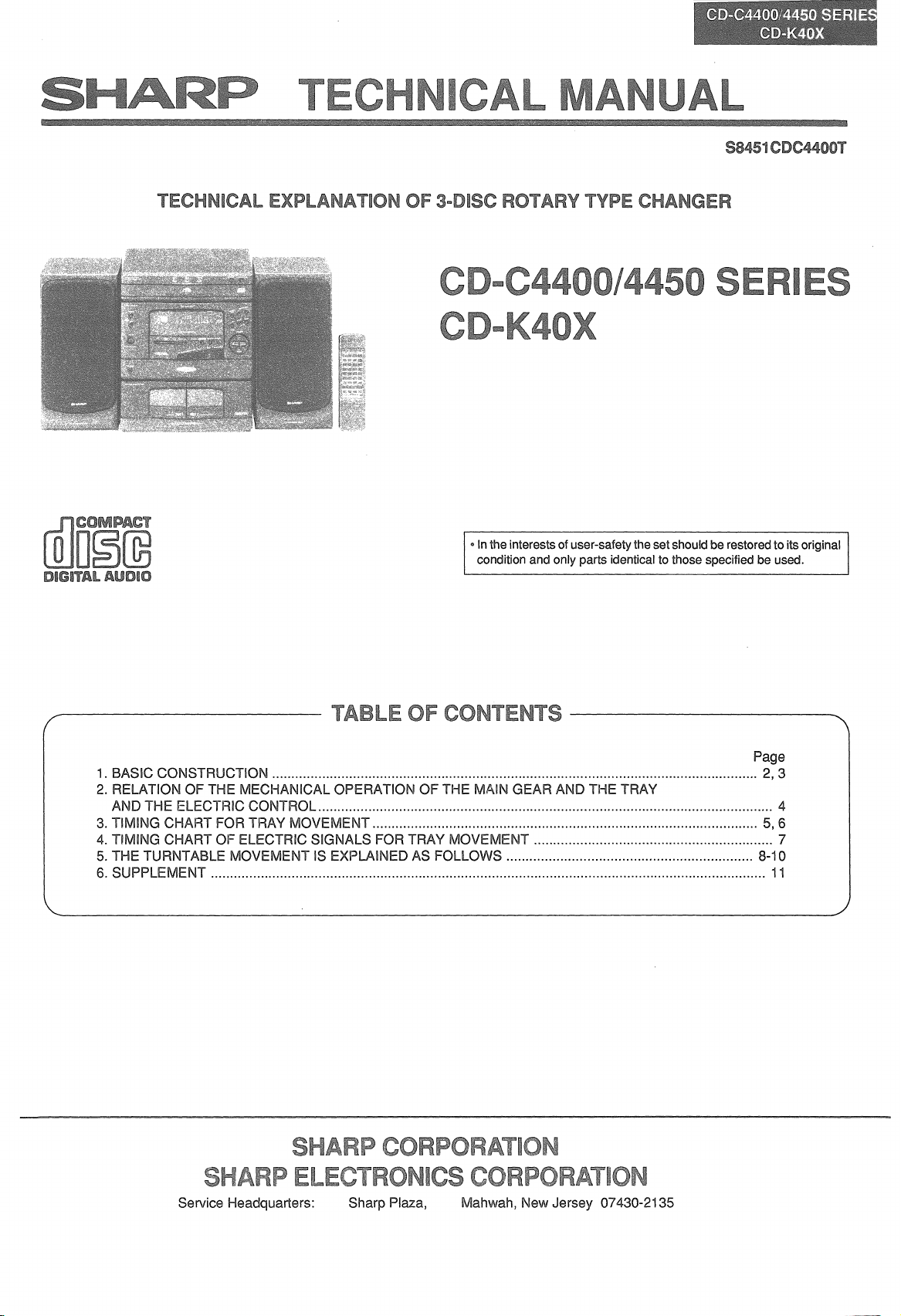
Page 1
Inthe interests of user-safety the set should be restored to its original
condition and only parts identical to those specified be used.
Page
1. BASIC CONSTRUCTION 2, 3
2. RELATION OF THE MECHANICAL OPERATION OF THE MAIN GEAR AND THE TRAY
AND THE ELECTRIC CONTROL 4
3. TIMING CHART FOR TRAY MOVEMENT
5,6
4. TIMING CHART OF ELECTRIC SIGNALS FOR TRAY MOVEMENT 7
5. THE TURNTABLE MOVEMENT IS EXPLAINED AS FOLLOWS 8-10
6. SUPPLEMENT 11
Service Headquarters: Sharp Plaza,
Mahwah, New Jersey 07430-2135
Page 2
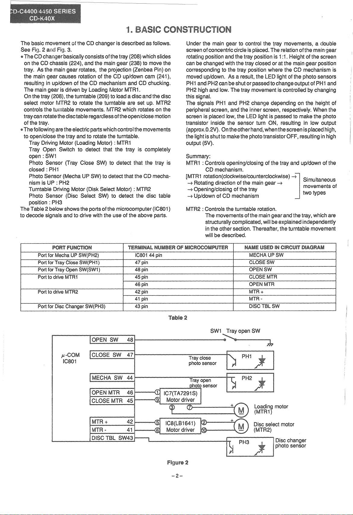
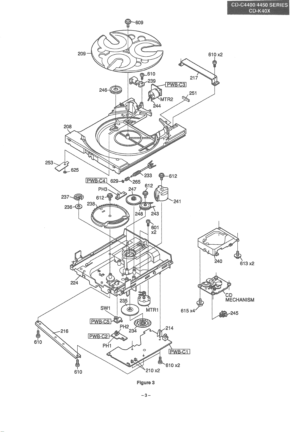
The basic movement the CD changer is describedas follows.
See 2 and 3.
• The CD changerbasicallyconsistsofthetray(208)whichslides
on the
CD chassis (224), and the maingear (238) to movethe
tray. As the maingear rotates, the projection (Zenbea
Pi.n)
on
the main gear causes rotation of the CD up/down cam (241),
resulting in up/down of the CD mechanism and CD chucking.
The maingear is driven by Loading Motor MTR1.
Onthetray (208),theturntable (209)toload a discandthe disc
select motor MTR2 to rotate the turntable are set up. MTR2
controls the turntable movements.MTR2 which rotateson the
traycanrotatethedisctableregardlessoftheopen/closemotion
of the tray.
•Thefollowingarethe electricpartswhichcontrolthemovements
to open/closethe tray and to rotatethe turntable.
Tray Driving Motor (Loading Motor) :
MTR1
Tray Open Switch to detect that the tray is completely
open:
SW1
Photo Sensor (Tray Close SW) to detect that the tray is
closed: PHi
PhotoSensor (Mecha UP SW)to detect that the CD mechanism is UP :PH2
Turntable Driving Motor (Disk Select Motor) : MTR2
Photo Sensor (Disc Select SW) to detect the disc table
position: PH3
TheTable
2 below showsthe portsofthemicrocomputer(IC801)
to decode signals and to drive with the use of the above parts.
Under the main gear to control the
screenofconcentriccircleisplaced.The relationofthe main
tray movements, a double
gear
rotatingpositionandthe tray position is 1:1. Height of the screen
can bechanged withthe trayclosed or at the maingear position
corresponding to the tray position where the CD mechanism is
movedup/down. As a result,the
LEDlight ofthe photo sensors
PH1and PH2canbe shutorpassedto changeoutput of PH1and
PH2 high and low.Thetray movementis controlledby changing
this signal.
The signals PHi and PH2 change depending on the height of
peripheralscreen, andthe inner screen, respectively.When the
screen is placed low, the LED lightis passed to makethe photo
transistor inside the sensor turn ON, resulting in low output
(approx.0.2V). Ontheotherhand,whenthe screenisplacedhigh,
the lightisshutto makethe phototransistorOFF,resultingin high
output (5V).
Summary:
MTR1
:Controls opening/closingof the tray and up/down of the
CD mechanism.
[MTR1
rotation(clockwise/counterclockwise)
tl d' tl f th . irnu aneous
R
t
~
0 a Ing irec Ion0 e main gear
~
Opening/closingof the tray
~
Up/downof CD mechanism
. wo ypes
~J
S' It
~
two
t f
tvoes S 0
MTR2 :Controls the turntable rotation.
The movementsofthe maingear and the tray,whichare
structurallycomplicated,will be explainedindependently
inthe othersection.Thereafter,the turntable movement
will be described.
PORT .-UN\.,;
Port for Macha UP SW(PH2)
Port for Tray Close SW(PH1)
Port for Tray Open SW(SW1)
Port to drive MTR1 45 pin
Port to drive MTR2
Port for Disc Changer SW(PH3)
IIVN
•
ICaDi
47 pin
48 pin
46 pin
42 pin
41 pin
43 pin
OPEN
}J.-COM
IC801
44 pin
OF MICROCOMPUTER
2
SW1
Tray close
photo sensor
NAME
MECHA
CLOSESW
OPENSW
CLOSE MTR
OPEN MTR
MTR+
MTRDISCTBLSW
Loading motor
(MTR1)
CIRCUIT DIAGRAM
UPSW
-2-
Discselect motor
(MTR2)
Disc changer
photosensor
2
Page 3
253
f-S09
-3-
613 x2
3
Page 4
In case the main gear rotates once clockwise while the CD
mechanism is not chucking a disc andthe tray isopen, a series of
movements are performed as follows:
The open tray is closed. Complete closing is followed by UP
movement of the CD mechanism (disc chucking movement).
When the main gear continuesrotation, a series of movementsto
open the tray is conducted again.
These movements are equivalent to the following actual use
condition; when the tray isopen, a disc is loaded on the turntable.
Then the tray is closed to play CD. In this play mode the tray is
opened.
'The reverse movements are performed by rotating the main
counterclockwise;
when
the main
gear
is rotated
gear
once
counterclockwisewhile the CD mechanism is chucking adisc and
the tray is open, the tray is closed. The DOWN movement of the
CD mechanism and then the tray open movement follows. The
movement to open/close the tray, which does not simply correspond to the rotating direction of the main gear, will change
according to the CD movement mode.
The Table 3 below shows the above-mentioned movement. The
CD stop condition is main in the actual use of the CD changer.
Figure 5-1to 5-6 and 6-1 to 6-6 shows a series ofprocess to close
the opening tray with the CD mechanism down, and Fig. 7, the
Timing Chart of Electric Signals.
The main gear to slide the tray is of rack' pinions.
Double pinion gearsof the main gear are set vertically. Their
diameters are slightly different. One gear with larger diameter
engages withthe rack gear onthe left sideofthetray;the otherone
with smaller diameter engages with the rackgear on the rightside
of the tray.
STATE
CD stop condition (CD Mechanism UP)
NU
I A I
INU
DIRECTION OF
CLOCKWISE
The tray is opened with CD Mechanism UP.
(In case the tray is opened in the CD mentioned left, the main gear is rotated
PLAY mode)
The tray is closed with CD Mechanism Down.
(In case the tray is opened by stopping CD.)
Movementdirection
To close the tray under the condition as
counterclockwise.
COUNTERCLOCKWISE
To close the tray under the condition as
mentioned left, the main gear is rotated
clockwise.
GEAR
COUNTERCLOCKWISE
CLOCKWISE
-4-
Page 5

CD
®
®
TRAY~
UP/DOWN
CAM
~
A
-..
MTR
160
POWER
OPEN
-e----+--
OFF
STOP
TRAY
LOCK
PIN
5=2
®
®
ZENE8A
PIN TO
TOUCH
5=6
Fig.
t
MA
5-1
:Thetray is completelyopen. At
IN GEAR TO FREE
[AJ,
MTR
STOP
FOR
TURNING
PH1;ON
D/T
DELAYED
OF
5·5
the lowergear with largerdiameterengageswith the rack gear on the leftside of thetray.
Tray Open ) ON : Low level
Presseitherthe Open/Closekey or the traytoturn
SW1
OFF(HIGH). Then
MTR1
startsrotatingclockwise. By the clockwise
rotationof the main gear, the tray is movedto close.
5-2:Whenthe maingear rotatesto this position,thetray lockpin beginsto enterthe guide ofthe maingear. Ifthe pinfurtherenters
Fig.
the inner part, the tray is locked in the close state.
Fig.5-3 : The maingear has rotatedfurther in comparisonwith the conditionshown in Fig.5-2.
Fig.5-4 : Whenthe main gear rotatesto this position,the rack gear of the tray andthe pinion gear of the main gear are disconnected.
Thereafterthe tray is moved the tray lock pin.
MTR1
Fig.5-5 :The tray is completelyclosedat this position.When theClose ) is ON,
regularposition.
the mechanism.When the turntable movesto the regularposition,
Ifthe CD mechanismmovesup whilethe turntable is not at its regularposition,theturntable will collidewith
MTR1
starts rotatingagainto advanceto the next step.
willstop untilthe turntablemovesto the
Fig.5-6 :TheZenebapinsetinthe maingearbeginsto contactthe Up/Downcamto movethe CDmechanismup/down.Atthis position,
theCD
mechanism
starts
moving
up.
-5-
Page 6

CENTER
®
8 <OPEN.DISC
-----L-
ZENEBA
PIN
CD
MECHAN
6
...
1
FREE
I8M UP
6
...
2
POSITION__..(9)
SKIP
PLAY
~
P.
I I
I I
1 1
1 i
t I
PLAY.
STOP
MECHA
UP -
MTR
PH2:0N
STOP
6
...
3
~
1--
GEAR
TOUCHTORACK
PH1
:OFF
GEAR
TRAY
LOCK
PIN TO
FREE
I
t
I
~
j
PLAY
TIME
OPEN
POWER
6-6
160mm
OFF
MTR
6
...
5
6-1 : The CD mechanism is in the UP movement after half rotation of the Up/Down cam.
Fig. 6-2 : The up movement of the CD mechanism has completed when the Up/Down cam finishes rotation. (Disc chucking completed)
Fig. 6-3 : The photo sensor (PH2) becomes low level; MTR1 stops. At this position CD stops. Disc chucking has been completed to wait
for CD Play.
6-4 : At the pinion gearwith smallerdiameter set in the main gearstarts engaging with the rack gearon the right side of the tray.
Then the tray starts opening.
The Close ) is level)
6-5 : At this position, the tray lock pin becomes free. The main gear and the tray rack gear engage to open the tray.
: The tray Open SW(SW1) is turned ON to stop MTR1 and to open the tray fully.
6-6
To
simplifythe description, we explained the case in which the main gearrotates clockwise"afterthe tray isopen. In the actual movements,
however, the
CD STOP condition is main as shown in Fig. 6-3.
-6-
Page 7

Pin
48
47
44
CLOSE
2
5 6 8 9
,t
"""""""'--------------""'"'11 I
,;
R
I I
iI
I I
R
10
I
I I
DR
I.
I.
I
I I
I D
I
I
I
I B I I
I B
D
D I
B
II II
B
I D
I
I B
.Ilrm-"li""""'"'-----------""""""---
D D
I I I
Tray
Tray
Opening
Opening
completed
started
12
Mechanism
Down---~
1
-7-
Page 8

[Outline] : The 3-disc rotary changer mechanism is to
rotate the turntable inside the tray whose OPEN/
CLOSE movement is controlled by the microcomputer.
This microcomputer detects the turntable address and
stop positions, and performsstart/stop ofthe turntable.
NO. INPUTI FUNCTION
UUBII"'UI
43
Input
DISCTBLSW
:_m-IIUN
To input the photo-interrupter in the slit under the turntable. To detect the position of the turntable by
. counting.
To detect the slowing-down time and the stop position of the rotary motor.
OF
-___....
.-
I
__
m
42 Output DISC CHG MTR + To output to control clockwise rotation, slowing-down, and stop of the turntable select motor.
41 Output
DISC CHG MTR -
To output to control counterclockwise rotation, slowing-down, and stop of the turntable rotary motor.
cnaneer mechanism
detectthe
disc
~nlr1tr.F\1
The position is detected in case that the memory disappeared
because
of service interruption, etc, in the initial state, and in
case of starting movement after ERROR.
PIN
NO.43
To detectthe turntableposition bythe input of
TBl
SW).
The disc table is rotated clockwise
MTR
+=[H]) to detectthe pulse which changes from [H] to [L]
approx. 35 msec after the DISC
TBl
NO.42:
SW changes from
(DISC
DISC CHG
[l]
[H].
(In case that the DISC
within 20 to 50 msec it changes from [H] to [L], the detected
pulse is recognized as the turntable address detection pulse).
The position ofthe STOP control signal which appears approx.
200 msec after the pulse will be the DISC address [1
In the turntable position detection mode, the turntable is
stopped at the DISC address [1].
TBl
SW changes from [L] to [H], and
l-
to
-8-
Page 9

Theturntablepositionis changed bythe movementto rotate
the turntable clockwise by 120 degrees (PIN No.42: DISC
CHGMTR+ =[H]),or counterclockwiseby 120degrees
No.41:DISC CHG MTR -= [H]).
The present DISC address is memorized accordingto the
degreesby whichthe positionischangedfromthe initialstate
(DISCaddress
[1
D.
Inthe ternary notation,counting is as follows:
+1 in case ofclockwise rotation
-1
incase of counterclockwise rotation
(Clockwise:1
--7 2 --7 3
~1~
2
(Counterclockwise: 1~3~2~1~3
a)Whenchangingtheturntableposition,therotatingdirection
is basedon theTable 9 below.
1
1 /
2
3
Clockwire
Counterclockwire
t
DISC
address
moved
b) Output of microcomputer in case of
counterclockwise rotation
PIN NO.
42 DISC CHG MTR + H L
41
Whenthe turntableis stopped normally,
DISCCHGMTR + =
DISCCHG MTR-
(41
= [L]
DISC CHG
[l]
Counterclockwire
Clockwire
fUNCTION
MiR
2
/
3
Clockwire
Counterclockwire
/
~
PresentDISCaddress
clockwise/
CLOCKWIRE COUNTERCLOCKWIRE
- L H
Table 9
-9-
Page 10

The slowing-down time and the stop position of the turntable
TBl
rotarymotor are detected by inputofPIN No.43 DISC
Approx. 2 sec after the turntable starts rotating, the STOP
control signal is input.
When the disc address moves from [3] to [1], or [1] to [3], the
disc address detection pulse (20 msec) is passed through.
Fromthe time when DISCTBL SW, asthe Stop control signal,
[l]
changes
of PIN No.42 DISC CHG MTR + for clockwise rotation, and
PIN No.41 DISC CHG MTR -torcountsrclockwlse rotationare
recognized respectively as the pulse signal with a cycle of
approx. 20 msec. (Approx. 100 msec)
Ifrotation isclockwise when DISC
DISC CHG MTR
MTR - (41 at for
the disc table is stopped.
For counterclockwise rotation, DISC CHG MTR set at [L], and DISC CHG MTR
simultaneously. As a result, the turntable is stopped.
to tothe time when itchanges output
TBl
SWchanges to [L],
+ (42PIN) is set at
1Omsec,simultaneously. Asa result,
+ (42PIN), at for 10 msec,
[l],
and DISC CHG
SW.
(41 is
In the cases a), b), and c) below, DISC CHG +
(42PIN) and DISCCHG - (41 are
"ERROR".
a) Input of DISC TBL SW(43PIN) does not,change within 1 to
6 seconds after the turntable starts rotating.
b) DISC
c) DISC
* For error recovery, turn the POWER switch OFF and then ON
again; the normal state is recovered and the turntable position
detection mode starts.
* Press the UP and DOWN keys simultaneously during the
"ERROR" display to indicate "rot. ERROR" for
TBl
after detecting the STOP control signal.
TBl
after the address detection pulse in the turntable position detection mode.
is not set approx. 5 seconds
is not set at approx. 5 seconds
~et
at to
seconds,
"ERROR" display
Rotary Error Display
OOMR
~~~O
M~MO~V
MlNlDOM
~~O~lF?!~M
C:)
~l~~~
~~c
C¢
(>
00
F D
OO~~
c:)
mk~U~O
M~MO~V
MNOOM
~~O~~AM
~L~le~
C¢
C>
00
AM
PM
~M
o PM
OU
c::::::=
o~o
Oc:=O
OU
aU
c:::=
~
D
o~oDo~o
U
o
·on
:0=0
ei
.c:::::,:)
ou
o~n
~
o~o
OU
0=0
(Crt={]
F D N
-10-
Page 11

<D
When the OPEN/CLOSE key is pressed during the disc
addressdetection,the tray is opened afterthe address detection. Once the OPEN/CLOSE key is pressed, "OPEN" is
displayed.
(g)
If RESET is ON when the tray is open during CD PLAY, the
tray is closed and the mechanism moved down to detect the
disc address.
® When the POWER key is pressed during the turntable rotation
orthe
movementofOPEN/CLOSE
OFF inthe Mecha UP state with the movement to the desired
position.
@)
When 33PIN(SYSTEM DOWN) becomes [L] to enter the
backup mode due to service interruption or pulling-out of the
AC cord, etc, the present disc address will be memorizeduntil
the RESET is ON.
If 44PIN MECHA UP SW shows [H] when POWER is turned
ON again, power supply may have been cut during the
turntable rotation. The turntable address detection mode will
start to detect the
disc address 1 again.
a) Clockwise rotation
(PIN No.) (Function)
43 DISC
TBl
POWER
Timing chart for Turntable STOP Control
SW
becomes
a) Incase of 44PIN MECHA UP SW = [H], and 47PIN CLOSE SW
=[L]
Aftertheturntable is moved tothe position where 46PIN OPEN
MTRis set at [H]and CLOSE
After the address detection, the Mecha UP state is attained.
b) In case of 44PIN MECHA-UPSW
=[H]
45PIN CLOSE MTR is set at and the tray is closed.
Simultaneously
When the CLOSE SW reaches [L], the tray motor is stopped
temporarilyto detectthe address. Aftertheturntableis stopped,
the CLOSE MTR is set at [H] again to attain the Mecha UP
state.
Disc address detection
pulse in case of Disc 3
.-Ji
the
turntableisrotatedtodetect
.
.
SWat
[H], theturntableis rotated.
=[H], and 47PIN CLOSESW
the
address.
-+
1
42 DISC CHG MTR +
41 DISC CHG MTR -
b) Counterclockwise rotation
(PIN No.) Function
43 DISC
42 DISC CHG MTR+
41 DISCCHG MTR -
TBl
SW
[ Shape of slit for DISC TBL SW ]
t
Turntable
rotation starts
Turntable
rotation starts
Disc 2
STOP Control Slit
2 sec
11
...
1
Disc address detection
pulse in case of Disc 1
35msec
11
...
2
-.3
100msec
I
,'tI
t
Slowing-down
starts
Slowing-down
starts
• B
iIill
t·
STOP
us
0
0
Disc 1
STOP
Clockwise~
rotation
120
Disc 2
STOP
0
360
Disc 1
STOP
Counterclockwise
rotation
3
240
Disc 3
STOP
0
-E---
0
11
...
-11-
Page 12

Writer and Editor:
&Reliabilitv Control Center of communtcanon &Audio svstems
IA9410-4394NS·HA·M
PrintedinJapan
In
Japan
lmprerne
SG·SK.SA.SZ.SC.SL.EX
gedruckt
au
Japan
 Loading...