

Page 1
Date: Jan. 20, 1994
COPIER : CX-7700
No. : CCT-84
CX-7700 PARTS CHANGES IN COMPLIANCE
WITH SAFETY STANDARDS.
1.General: Var ious parts of the 200 V series of model CX-7700 have been changed in compliance
with safety standard demands.
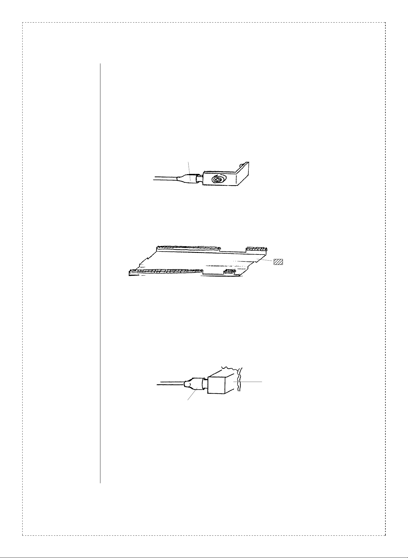
2.Description: 1. Copy lamp unit.
Heat reducing tubes (4 locations) have been added to the terminal area (Fig. 1).
Mylar tape has been attached to the edge of the wiring path (Fig. 2).
2. Zoom lens unit.
A reducing tube has been added to the drying heater terminal (Fig. 3.)
3. Drive unit.
Edge bushings (4 locations) have been added to the upper surface of the drive unit
frame (Fig. 4).
4. Rear frame.
An edge bushing has been added to the attachment plate angle of the slave circuit
board (Fig. 5).
An edge bushing has been added to the attachment plate of the slave circuit board
(Fig. 6 ).
An edge bushing has been added to the holding plate of the main circuit board (Fig. 7).
5. Lower frame.
An edge bushing has been added to the right fulcrum angle (Fig. 8).
A bushing has been added to the suction fan attachment angle (Fig. 9).
6. DV motor.
A protection sheet has been added to the motor lead (Fig. 10).
7. Fixing unit.
Edging has been added to the oil tank holding plate area (Fig. 11 and 12).
A protection sheet has been added to the oil tank holding plate area (Fig. 11, 13 and
14).
A protection sheet has been added to the thermostat attachment plate (Fig. 15).
The fixing unit harness has been changed (Fig. 16).
SHARP CORPORATION Reprography Division
1/7
Green
C
Page 2
An edge protection coil has been added (Fig. 16).
A heat resistant clamp has been added (Fig. 16).
The screws have been changed (Fig. 16).
1. Copy lamp unit.
Added heat reducing tube.
Fig. 1
2. Zoom lens unit.
Edge mylar tape attac hed
to the shaded areas.
Fig. 2
Drying heater.
Reducing tube.
Fig. 3
2/7
Page 3
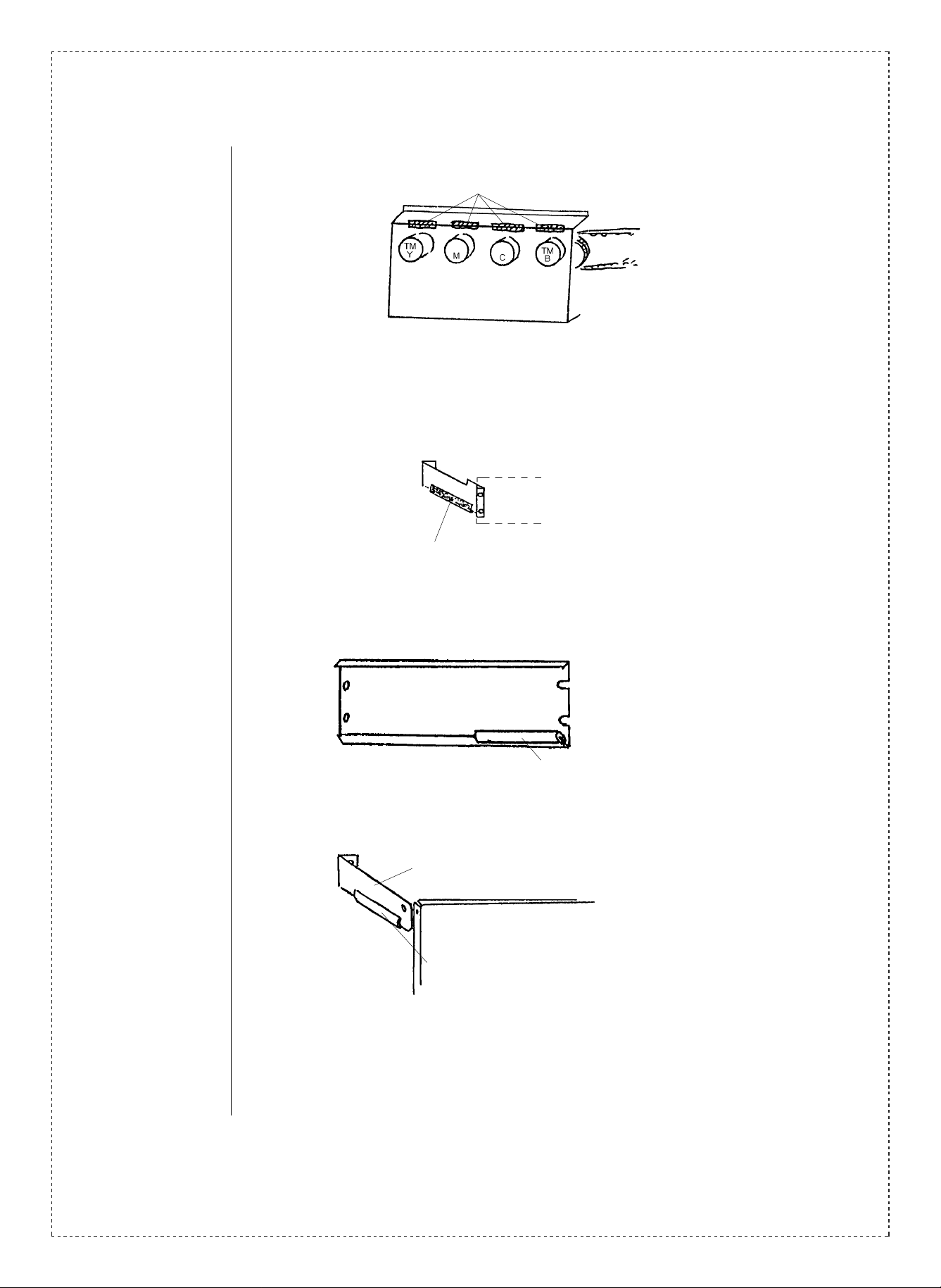
3. Drive unit.
4. Rear frame.
Edge bushing CE-016.
Drive unit 220 (V).
CFRM-0526FC
Fig. 4
PHOG-7003XCZZ
Fastened with instantaneous adhesion glue.
.
**
Slave circuit board
attachment plate.
Fig. 5
Slave circuit board
attachment plate.
(LPLTM2811FCZZ)
PHOG-1007HCZZ
Fig. 6
Main circuit board holding plate.
(LPLTM2749FCZZ)
PHOG-2029SCZZ
Fastened with instantaneous adhesion glue.
Fig. 7
3/7
Page 4

5. Lower frame.
Rear frame angle (CANGT1249FC2)
LBSHC0282FCZZ
Standard installment of bottom surface.
Fig. 8
Added.
LBSHC7004SCZZ
6. DV motor.
Rear frame.
Fig. 9
PSHEP3083FCZZ
DV motor.
Fixed by inserting into the motor screw area.
Fig. 10
4/7
Page 5

7. Fixing unit.
Fig. 11
Section A of the left diagram.
LBSHC0281FCZZ x2
=17mm
CE024
LBSHZ7004GCZZ x1
@=3.00
Fig. 12
Section B and section B’ of the left diagram.
Held in position by the
lead wire after inserting.
Lead wire.
Section C of the diagram above.
Bottle-neck holder.
Lead wire.
Fig. 14
PSHEZ3082FCZZ (Protection sheet FU3.)
Fig. 13
PSHEZ3081FCZZ
Protection sheet FU2.
Fixing unit rear frame.
Tightened.
5/7
Page 6

M3 x 6 S/SW
Rear.
Fixing unit front frame.
M3 x 6 S/SW
Insert under the metal plate.
PSHEZ3080FCZZ
Fig. 15
Front.
Thermostat attachment plate.
PSHEZ3080FCZZ
Added edge protection coil.
Added heat resistant clamp.
Changed screw.
M4 x 6 with SW
M4 x 6 with S/SW.
Changed tightening screw.
M4 x 6 with SW
M4 x 8 with S/SW.
Changed fixing unit
harness ?????.
Electrode holder.
Heater.
Fig. 16
6/7
Page 7

Ref.
No.
1
Model
name
Version P/G No.
200V
11 -501 CREFL0130FC37 CREFL0131FC38 BW Copy lamp unit
series
Current parts New parts
Parts code Parts code
Price
rank
Parts name
Effec-
tive
time
Inter-
change-
ability
1
Note
2
3
4
5 220V
6
CX-7700
7
220V
SEEG
only
ALL
SEEG
only
ALL 20 -6 DHAI-1559FCZZ DHAI-1559FC12 AH
SEEG
only
12 —3 CR-WZ0247FC04 CR-WZ0247FC10 AV Drying heater 1
19 — PHOG-7001SCZZ AV
4
4
8
23 — LBSHC0282FCZZ AV —
23 — LBSHC7004SCZZ AB Bushing —
8
20 — LBSHC0281FCZZ AB
20
20
20 — PSHEZ3081FCZZ AL
20
20 — XBPSD30P06KSD AA Screws (M3 x 6) —
20 — MSPRC1991FCZZ AA
20 — LHLDW0433FCZZ AD
20 -B48 XBPSD40P06K00 XBPSD40P06KSD AA Screw (M4 x 8) 1
— PHOG-7003XCZZ AV —
— PHOG-1007HCZZ AV —
— PHOG-2029SCZZ AV —
— PSHEP3083FCZZ AD Protection sheet —
— LBSHC7004GCZZ AB — Q’ty: 1
— PSHEZ3082FCZZ AL
— PSHEZ3080FCZZ AG
Edge bushing
Edge bushing
Protection sheet
FU 3
Protection sheet
FU 2
Protection sheet
FU 1
Fixing unit
harness
Edge protection
coil
Heat resistant
clamp
92/12
— Q’ty: 4
Q’ty: 1
— Q’ty: 2
— Q’ty: 2
— Q’ty: 1
—
Q’ty: 2
1
—
Q’ty: 1
—
20 -B48
<Interchange>
1. Interchangeable. 4. Not interchangeable.
2. C urr e nt t y pe c a n be u s ed i n place of n ew type.
New ty pe cann ot be us ed in place of curr ent type .
3. C urr e nt type cannot b e us e d in p l ac e o f ne w ty p e.
New t y pe c a n be u s ed i n pl a ce of curr en t ty p e.
Parts m ar ke d wi th “ ” is imp or t an t fo r mai n ta in ing t he s a fe ty of t he se t. Be sur e t o rep l ac e t he se pa r ts wi th
specified ones for maintaining the safety and performance of the set.
!
XBPSD40P06K00 XBPSD40P08K00 AA Screw (M4 x 8) 1
5. Interc ha ng ea ble i f r ep l ace d wi th s a m e typ es of
relate d pa r ts in use.
6. Others.
7/7
 Loading...