

BS120
BS120
Photodiode for Visible Light
■ Features
1. Spectral sensitivity characteristics akin to
that of human eye
2. Compact flat package
3. Low dark current (Id:MAX. 10
=1V
R
)
V
-11
A at
4. Infrared light cut-off type
■ Applications
1. AE (automatic exposure) system and ES
(electronic shutter) system for cameras
2. Stroboscopes
3. Precise optical instruments
■ Absolute Maximum Ratings
Parameter
Reverse voltage
Operating temperature
Storage temperature
*1
Soldering temperature
*1 For 10 seconds
Symbol Rating Unit
V
R
T
opr
T
stg
T
sol
10 V
-20 to + 60
-30 to + 80
260 ˚C
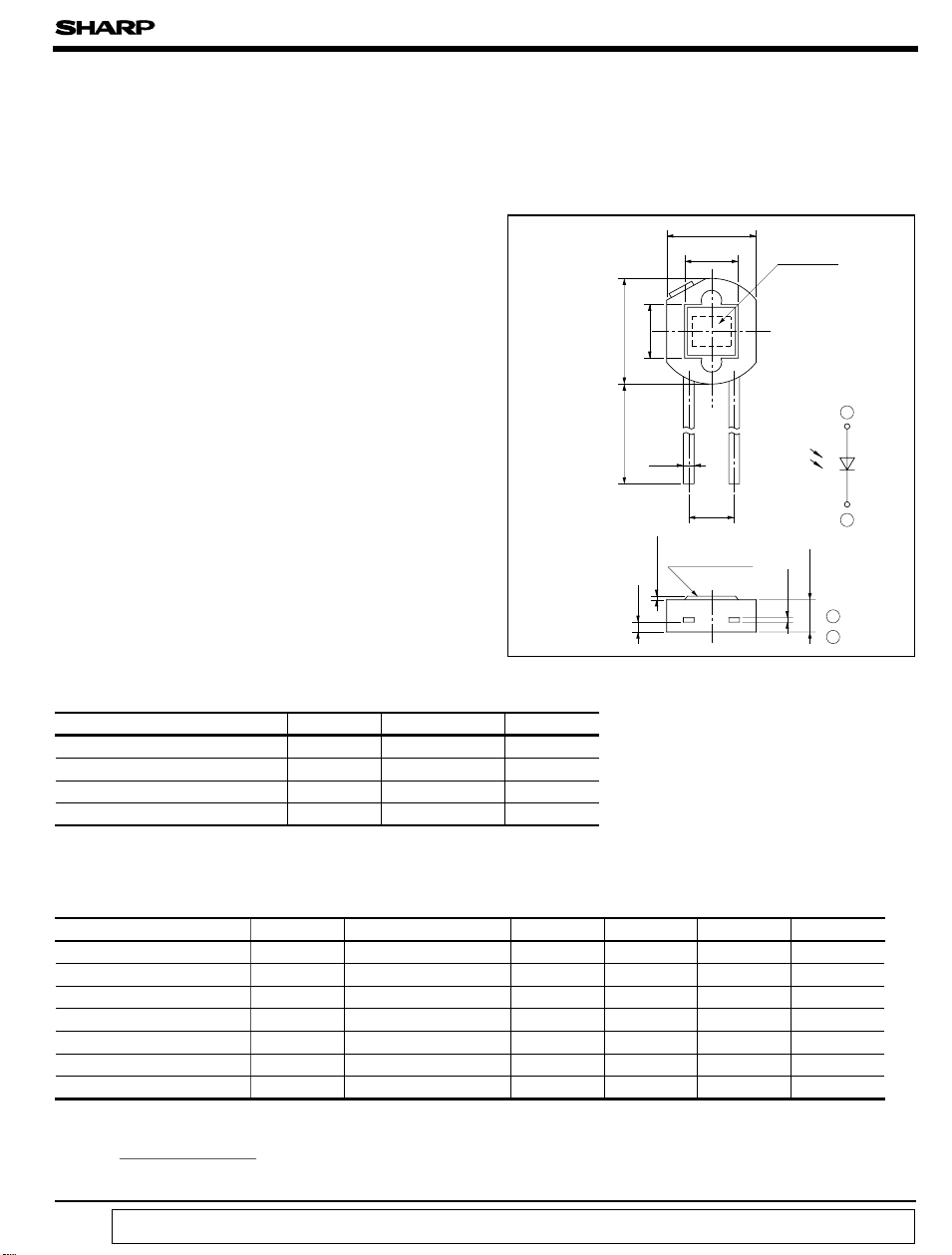
■ Outline Dimensions
5.0
± 0.2
3
φ 5.9
± 1.0
8.0
0.6
Infrared light
cut-off filter
MAX.
0.2
Active area:
1.55mm
(
Ta=25˚C
˚C
˚C
0.55
2
)
± 0.2
2
2.54
(
Unit:mm
3
Element
1
1
2
± 0.1
1.8
0.25
1 Anode
2 Cathode
)
■Electro-optical Characteristics
(
Ta= 25˚C
Parameter Symbol Conditions MIN. TYP. MAX. Unit
*2
Short circuit current I
Short circuit current tempe-
*2
rature coefficient
Dark current I
Dark current temperature
coefficient
Terminal capacitance C
Peak sensitivity wavelength
*4
Spectral sensitivity
infrared radiation ratio
*2 EV: Illuminance by CIE standard light source A (tungsten lamp
*3 times/10˚C
∆I
*4
(
λ>=700nm
I
SC
= x100%
R
(
full wavelength
I
SC
“ In the absence of confirmation by device specification sheets, SHARP takes no responsibility for any defects that occur in equipment using any of SHARP's devices, shown in catalogs,
data books, etc. Contact SHARP in order to obtain the latest version of the device specification sheets before using any SHARP's device. ”
)
SC
β
T
d
α
T
t
λ
p
∆I
R
)
E
= 100lx
V
E
= 100lx
V
VR=1V - 3x10
VR= 1V - 3.5 5.0
0.14 0.16 0.21 µ A
- 0.03 0.02 0.07 %/˚C
-12
-11
10
*3
VR= 0, f= 1MHz - - 500 pF
-
-
)
500 560 600 nm
-
610%
)
A
times/10˚C
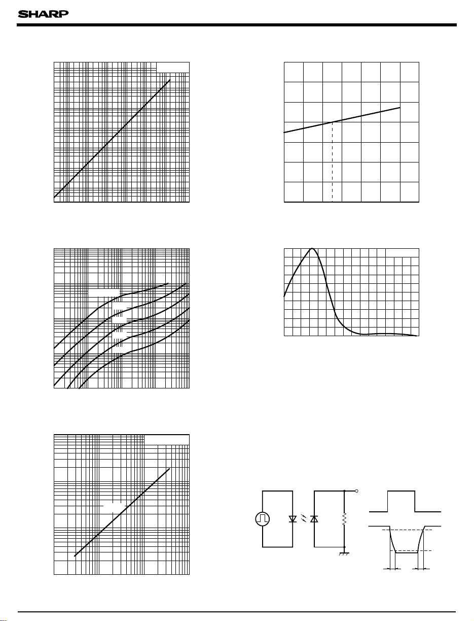
Fig. 2 Relative Short Circuit Current vs.Fig. 1 Short Circuit Current vs. Illuminance
-5
10
5
-6
10
5
)
-7
10
A
(
5
SC
-8
10
5
-9
10
5
-10
10
5
Short circuit current I
-11
10
5
-12
10
10-310-210
-1
555555
110
Illuminance EV (rx
Ta= 25˚C
10210
)
3
Ambient Temperature
103
102
)
%
(
101
100
99
98
Relative short circuit current
97
96
0 10202530405060
Ambient temperature Ta (˚C
Fig. 3 Dark Current vs. Reverse Voltage Fig. 4 Spectral Sensitivity
-9
10
5
2
-10
10
5
)
A
(
2
d
-11
10
5
2
Dark current I
-12
10
5
2
-13
10
-3
10
Ta= 60˚C
50˚C
40˚C
30˚C
20˚C
-2
5
2 555222
10
Reverse voltage VR (V
-1
10
110
)
100
90
)
80
%
(
70
60
50
40
30
20
Relative sensitivity
10
0
400 500 600 700 800 900
Wavelength λ (nm
BS120
)
Ta= 25˚C
1000 1100 1200
)
Fig. 5 Response Time vs. Load Resistance
1000
500
)
200
µ s
(
100
f
, t
r
50
t
, t
r
20
10
Response time t
f
5
2
112 5 10 20 50 100 200 500
Load resistance RL (k Ω
T
)
= 25˚C
a
1000
● Please refer to the chapter “Precautions for Use.”
Test Circuit for Response Time
Infrared LED
Pulse generator
BS120
Output
R
L
Input
Output
90%
10%
t
r
t
f
 Loading...