

Page 1

TopPage
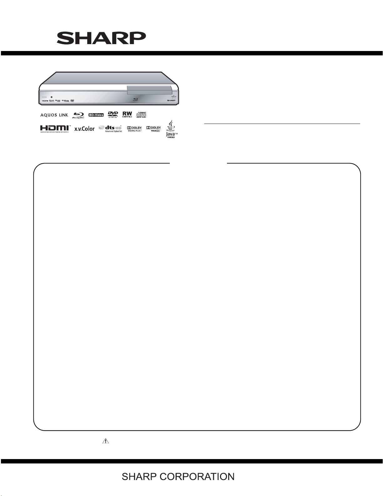
BD-HP21U
SERVICE MANUAL
No. S88M8BDHP21U/
BLU-RAY DISC PLAYER
MODEL
In the interests of user-safety (Required by safety regulation in so me countries) the set sh ould be restored to its
original condition and only parts identical to those specified should be used.
BD-HP21U
CONTENTS
SAFETY PRECAUTION
IMPORTANT SERVICE NOTES.........................i
Precautions for using lead-free solder ..............iii
CHAPTER 1. SPECIFICATIONS
[1] SPECIFICATIONS .........................................1-1
CHAPTER 2. OPERATION MANUAL
[1] PARTS NAMES.............................................. 2-1
CHAPTER 3. REMOVING OF MAJOR PARTS
[1] REMOVING OF MAJOR PARTS ................... 3-1
[2] EXTENSION CABLE CONNECTION DIA-
GRAM ............................................................3-4
[3] IMPORTANT SERVICE NOTICE...................3-6
[4] UPGRADING .................................................3-6
CHAPTER 4. BLOCK DIAGRAM
[1] MAIN BLOCK DIAGRAM ............................... 4-1
[2] ANALOG/LCD/OPERATION BLOCK DIA-
GRAM ............................................................4-2
CHAPTER 5. SCHEMATIC DIAGRAMS
[1] MAIN (1) CIRCUIT SCHEMATIC DIA-
GRAM ............................................................5-1
[2] MAIN (2) CIRCUIT SCHEMATIC DIA-
GRAM ............................................................5-2
[3] MAIN (3) CIRCUIT SCHEMATIC DIA-
GRAM ............................................................5-3
[4] MAIN (4) CIRCUIT SCHEMATIC DIA-
GRAM ............................................................5-4
[5] MAIN (5) CIRCUIT SCHEMATIC DIA-
GRAM ............................................................5-5
[6] MAIN (6) CIRCUIT SCHEMATIC DIA-
GRAM ............................................................5-6
[7] MAIN (7) CIRCUIT SCHEMATIC DIA-
GRAM............................................................5-7
[8] MAIN (8) CIRCUIT SCHEMATIC DIA-
GRAM............................................................5-8
[9] MAIN (9) CIRCUIT SCHEMATIC DIA-
GRAM............................................................5-9
[10] MAIN (10) CIRCUIT SCHEMATIC DIA-
GRAM..........................................................5-10
[11] ANALOG CIRCUIT SCHEMATIC DIA-
GRAM..........................................................5-11
[12] POWER (1) CIRCUIT SCHEMATIC DIA-
GRAM..........................................................5-12
[13] POWER (2) CIRCUIT SCHEMATIC DIA-
GRAM..........................................................5-13
[14] POWER (3) CIRCUIT SCHEMATIC DIA-
GRAM..........................................................5-14
[15] OPERATON CIRCUIT SCHEMATIC DIA-
GRAM..........................................................5-15
[16] LCD CIRCUIT SCHEMATIC DIAGRAM......5-17
CHAPTER 6. PRINTED WIRING BOARD ASSEMBLIES
[1] MAIN PWB ....................................................6-1
[2] ANALOG PWB ..............................................6-5
[3] POWER PWB................................................6-7
[4] OPERATION-L PWB .....................................6-9
[5] OPERATION-R PWB...................................6-10
[6] LCD PWB ....................................................6-11
[7] SPACER PWB.............................................6-12
Parts Guide
Parts marked with " " are important for maintaining the safety of the set. Be sure to replace these parts with specified ones for maintaining the
safety and performance of the set.
This document has been published to be used for
after sales service only.
The contents are subject to change without notice.
Page 2
BD-HP21U
BDHP21U
SAFETY PRECAUTION
IMPORTANT SERVICE NOTES
IMPORTANT SERVICE NOTES
ServiceManual
Note:
This unit can be used only where the power
supply is AC 120V, 60Hz.
It cannot be used elsewhere.
CAUTION:
USE OF CONTROLS OR ADJUSTMENTS OR
PERFORMANCE OF PROCEDURES OTHER
THAN THOSE SPECIFIED HEREIN MAY RESULT
IN HAZARDOUS RADIATION EXPOSURE.
DO NOT STARE INTO THE LASER BEAM OR
VIEW WITH OPTICAL INSTRUMENT.
WARNING:
TO REDUCE THE RISK OF FIRE OR ELECTRIC
SHOCK, DO NOT EXPOSE THIS EQUIPMENT TO
RAIN OR MOISTURE.
TO REDUCE THE RISK OF FIRE OR ELECTRIC
SHOCK, AND ANNOYING INTERFERENCE, USE
THE RECOMMENDED ACCESSORIES ONLY.
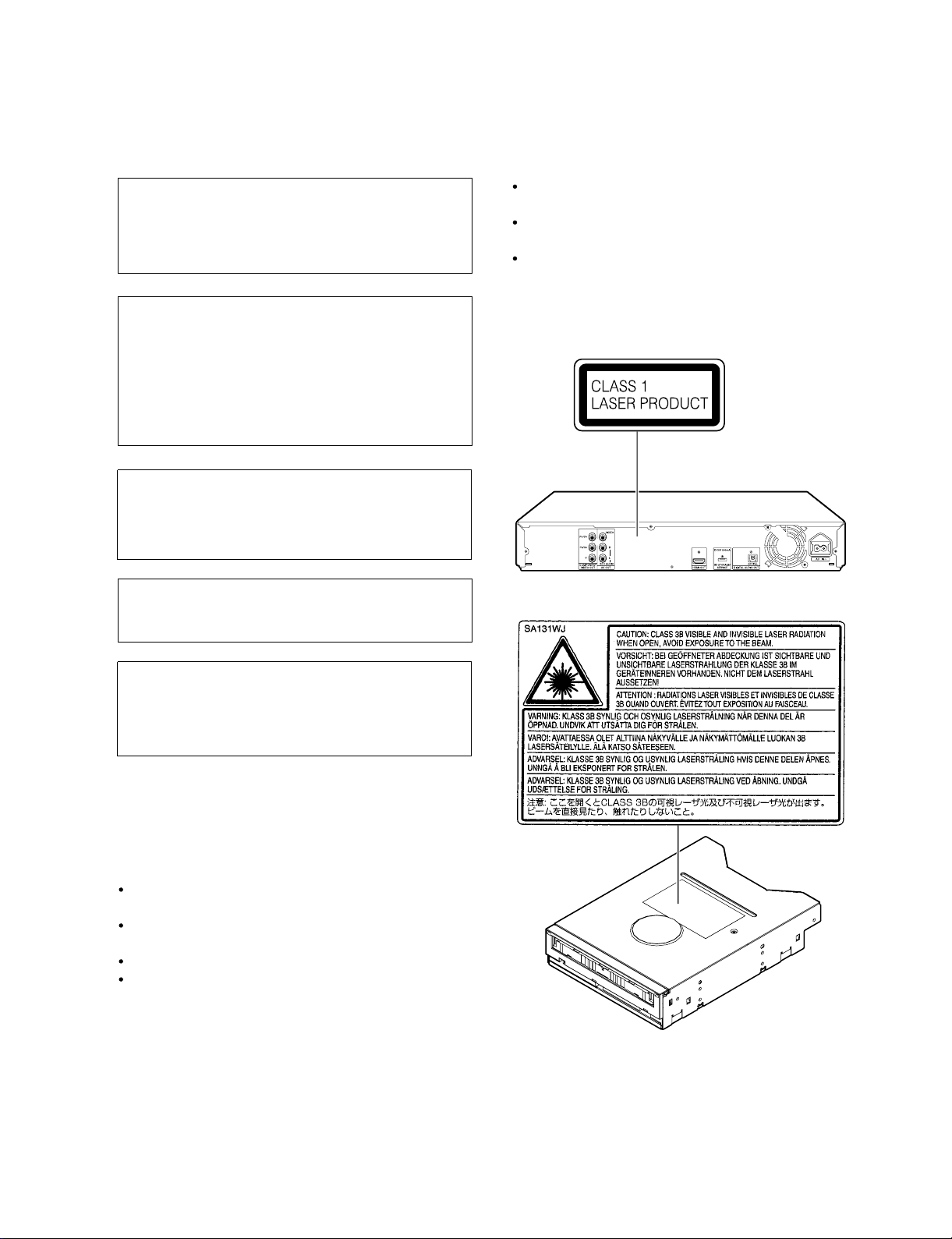
This Unit is classified as a CLASS 1 LASER
product.
The CLASS 1 LASER PRODUCT label is located
on the rear cover.
This product contains a low power laser device.
To ensure continued safety do not remove any
cover or attempt to gain access to the inside of
the product. Refer all servicing to qualified
personnel.
(Rear of product)
Laser Diode Properties
Material: AlGaInP
Wave length: 650 nm
Emission Duration: Continuous
Laser output: Max. 0.7 mW
Power Cord Protection
To avoid any malfunctions of the unit, and to protect
against electric shock, fire or personal injury, please
observe the following.
Hold the plug firmly when connecting or
disconnecting the AC power cord.
Keep the AC power cord away from heating
appliances.
Never put any heavy object on the AC power cord.
Do not attempt to repair or reconstruct the AC
power cord in any way.
VARO! AVATTAESSA OLET A LTTIINA LASERS ÄTEILYLLE.
ÄLÄ TUIJOTA SÄTEESEEN ÄLÄKÄ KATSO SITÄ OPTISEN LAITTEEN LÄPI.
VARNING - LASERSTRÅLNING NÄR DENNA DEL ÄR ÖPPNAD.
STIRRA EJ IN STRÅLEN OCH BETRAKTA EJ STRÅLEN GENOM OPTISKT
INSTRUMENT.
i
Page 3

IMPORTANT SERVICE SAFETY PRECAUTION
Service work should be performed only by qualified service technicians who are thoroughly familiar with all safety checks and the
servicing guidelines which follow:
BD-HP21U
WARNING
1. For continued safety, no modification of any circuit should be
attempted.
2. Disconnect AC power before servicing.
CAUTION: FO R CON TIN UE D PROTECTION
AGAINST A RISK OF FIRE REPLACE ONLY WITH
SAME TYPE FUSE.
F901 (125V 3A)
Use an AC voltmeter having with 5000 ohm per volt, or higher, sensitivity or measure the AC voltage drop across the resistor.
Connect the resistor connection to all exposed metal parts having a
return to the chassis (antenna, metal cabinet, screw heads, knobs
and control shafts, escutcheon, etc.) and measure the AC voltage
drop across the resistor.
All checks must be repeated with the AC cord plug connection
reversed. (If necessary, a nonpolarized adaptor plug must be used
only for the purpose of completing these checks.)
Any reading of 0.75 Vrms (this corresponds to 0.5 mA rms AC.) or
more is excessive and indicates a potential shock hazard which
must be corrected before returning the monitor to the owner.
DVM
BEFORE RETURNING THE BD PLAYER (Fire &
Shock Hazard)
Before returning the BD player to the user, perform the following
safety checks:
3. Inspect all lead dress to make certain that leads are not pinched,
and check that hardware is not lodged between the chassis and
other metal parts in the receiver.
4. Inspect all protective devices such as non-metallic control knobs,
insulation materials, cabinet backs, adjustment and compartment
covers or shields, isolation resistor-capacitor networks, mechanical
insulators, etc.
5. To be sure that no shock hazard exists, check for leakage current in
the following manner.
Plug the AC cord directly into a 120 volt AC outlet.
Using two clip leads, connect a 1.5k ohm, 10 watt resistor paral-
leled by a 0.15
parts and a known earth grou nd, such as electrical conduit or electrical ground connected to an earth ground.
///////////////////////////////////////////////////////////////////////////////////////////////////////////////////////////////////////////////////////////////////////////////////////////////////////////////////////////////////////////
F capacitor in series with all exposed metal cabinet
TO EXPOSED
METAL PARTS
AC SCALE
1.5k ohm
10W
0.15µF
TEST PROBE
CONNECT TO
KNOWN EARTH
GROUND
SAFETY NOTICE
Many electrical and mechanical parts in BD player television have
special safety-related characteristics.
These characteristics are often not evident from visual inspection, nor
can protection afforded by them be necessarily increased by using
replacement components rated for higher voltage, wattage, etc.
Replacement parts which have these special safety characteristics are
identified in this manual; electrical components having such features
are identified by " " and shaded areas in the Replacement Parts List
and Schematic Diagrams.
///////////////////////////////////////////////////////////////////////////////////////////////////////////////////////////////////////////////////////////////////////////////////////////////////////////////////////////////////////////
For continued protection, replacement parts must be identical to those
used in the original circuit.
The use of a substitute replacement parts which do not have the same
safety characteristics as the factory recommended replacement parts
shown in this service manual, may create shock, fire or other hazards.
ii
Page 4

BD-HP21U
Precautions for using lead-free solder
Employing lead-free solder
• “All PWBs” of this model employs lead-free solder. The LF symbol indicates lead-free solder, and is attached on the PWBs and service manuals.
The alphabetical character following LF shows the type of lead-free solder.
Example:
L Fa
Indicates lead-free solder of tin, silver and copper.
Indicates lead-free solder of tin, silver and copper.
L F a/a
Using lead-free wire solder
• When fixing the PWB soldered with the lead-free solder, apply lead-free wire solder. Repairing with conventional lead wire solder may cause damage or accident due to cracks.
As the melting point of lead-free solder (Sn-Ag-Cu) is higher than the lead wire solder by 40 °C, we recommend you to use a dedicated soldering
bit, if you are not familiar with how to obtain lead-free wire solder or soldering bit, contact our service station or service branch in your area.
Soldering
• As the melting point of lead-free solder (Sn-Ag-Cu) is about 220 °C which is higher than the conventional lead solder by 40 °C, and as it has poor
solder wettability, you may be apt to keep the soldering bit in contact with the PWB for extended period of time. However, Since the land may be
peeled off or the maximum heat-resistance temperature of parts may be exceeded, remove the bit from the PWB as soon as you confirm the
steady soldering condition.
Lead-free solder contains more tin, and the end of the soldering bit may be easily corroded. Make sure to turn on and off the power of the bit as
required.
If a different type of solder stays on the tip of the soldering bit, it is alloyed with lead-free solder. Clean the bit after every use of it.
When the tip of the soldering bit is blackened during use, file it with steel wool or fine sandpaper.
• Be careful when replacing parts with polarity indication on the PWB silk.
Lead-free wire solder for servicing
Part No. Description Code
ZHNDAi123250E J φ0.3mm 250g (1roll) BL
ZHNDAi126500E J φ0.6mm 500g (1roll) BK
ZHNDAi12801KE J φ1.0mm 1kg (1roll) BM
iii
Page 5

BDHP21U
CHAPTER 1. SPECIFICATIONS
ServiceManual
[1] SPECIFICATIONS
General
Power supply AC 120V, 60Hz
Power consumption (Normal) 23 W
Power consumption (Standby) 0.4 W (When "QUICK START" is set to "NO")
Dimensions
Weight Approx. 8.8 lbs. (4.0 kg)
Operating temperature 41°F to 95°F (5°C to 35°C)
Storage temperature -4°F to 131°F (-20°C to 55°C)
Operating humidity 10 % to 80 % (no condensation)
TV systems NTSC system
Approx. 16
Approx. 430 mm x 68 mm x 335 mm (W x H x D)
59
/64x211/16x133/16inch (W x H x D)
Playback
BD-HP21U
Playable discs BD-ROM, BD-RE Dual Layer (BDMV format), BD-R Dual Layer (BDMV format),
DVD Video, DVD+RW/+R/-RW/-R/-R Dual Layer (Video/VR format),
Audio CD (CD-DA), CD-RW/R (CD-DA, JPEG file format)
Input/Output
HDMI HDMI 19-pin standard connector (1080p 24Hz output)
Component video output Output level:
Video output Output level: 1 Vp-p (75 ohms)
Digital audio optical output Terminal: Square Optical terminal
Audio output Output level: 2 V rms (Output impedance: 1K ohms)
USB input USB 2.0 correspondence (for Local storage/Software update)
Specifications are subject to change without notice.
TM
HDMI
Jacks: RCA jack
Jack: RCA-pin jack
Jacks: RCA jack
(V.1.3 with x.v.Color, Dolby TrueHD, DTS-HD Advanced Digital Out )
Y: 1 Vp-p (75 ohms)
B/CB,PR/CR
P
: 0.7 Vp-p (75 ohms)
1 – 1
Page 6

BD-HP21U
BDHP21U
CHAPTER 2. OPERATION MANUAL
[1] PARTS NAMES
1. MAIN Unit
Main Unit (Front)
1 43
2
58
ServiceManual
1
2
3
4
5
6
7
8
POWER
Remote control sensor
Disc tray
OPEN/CLOSE
ON indicator
STANDBY indicator
Front panel display
BD/DVD/CD mode indicator
6
Main Unit (Rear)
1 2
3
7
COMPONENT VIDEO OUT jacks
1
VIDEO output jack
2
3
2CH AUDIO output jacks
4
HDMI OUT terminal
5
BD STORAGE/SERVICE terminal
BD STORAGE
SERVICE for software
DIGITAL AUDIO OUT OPTICAL
7
8
6
terminal
Cooling fan
7
The cooling fan operates while the
power to the Player is on.
AC IN terminal
8
64 5
2 – 1
Page 7
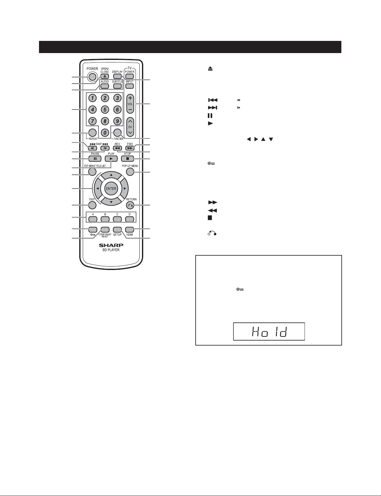
2. Remote Control Unit
Remote Control Unit
1
2
3
4
5
6
7
8
9
10
11
12
13
14
15
16
17
18
19
20
21
22
23
24
25
POWER
1
2
3
4
5
6
7
8
9
10
11
12
13
14
15
16
17
18
19
20
21
22
23
24
25
OPEN/CLOSE
AUDIO, SUBTITLE
Number buttons
REPEAT
SKIP/
SKIP/
PAU S E
PLAY
TOP MENU/TITLE LIST
Cursor buttons ( / / / ), ENTER
EXIT
A (Red), B (Green), C (Blue), D (Yellow)
(Lock) (See below.)
COMPONENT RESET
DISPLAY
TV CONTROL buttons
FUNCTION
FWD
REV
STOP
POP-UP MENU
RETURN
HDMI
SETUP
BD-HP21U
Keylock function
You can set the keylock to prevent accidental operations.
This function allows TVs compatible with AQUOS LINK to
also perform a Key Lock on the player.
Press and hold
Each time you perform this operation, the function is activated
•
or deactivated.
If you try to operate the Player while the keylock function is
•
set, “Hold” blinks on the front display panel to indicate that the
keylock function is set.
(Lock) for more than 5 seconds.
2 – 2
Page 8

BD-HP21U
BDHP21U
CHAPTER 3. REMOVING OF MAJOR PARTS
ServiceManual
[1] REMOVING OF MAJOR PARTS
1. Removing the tray cover
1. Eject the tray by inserting a pin into the compulsory eject hole, then remove the tray cover.
Insert
a pin
Tray cover
2. Removing the cabinet and the panel
1. Remove two screws and three screws from the top cabinet.
2. Unhook claws of the front panel and remover the front panel.
Top cabinet
1
2
1
Front panel
3 – 1
Page 9

3. Removing the BD drive
1. Disconnect the SATA cable and power cable.
2. Remove four screws and remove the BD unit (with the angle) upward.
3. Remove four screws and remove the BD unit.
BD-HP21U
Power cable
3
4
BD drive
angle (Left)
3
BD
drive
4
4. Removing the front PWB
1. Disconnect the LCD FFC between the LCD PWB and power PWB.
2. Disconnect the Connecting cord (Operation-R-Power) and Connecting cord (Power-Analog).
SATA cable
3
BD drive
angle
(Right)
3. Remove three screws .
4. Remove one screw .
5. Remove the operation PWB angles (left and right).
Operation PWB
angle (Left)
Oreration PWB
(Left)
5
5
LCD
PWB
Oreration PWB
(Right)
6
LCD FFC
Operation PWB
angle (Right)
Connecting cord
(Power-Analog)
5
Spacer
PWB
Connecting cord
(Operation-R-Power)
3 – 2
Page 10

BD-HP21U
5. Removing the fan and the rear terminal board
1. Remove two screws .
2. Remove six screws .
3. Disconnect the fan cable connector and remove the fan.
Fan
8
7
8
Rear terminal board
6. Removing each PWB
1. Disconnect the board to board connectors from each PWB.
2. Disconnect the board to board connectors (two) from the main PWB and analog PWB, then remove one screw .
Disconnect the board to board connector (two) between the main PWB and power PWB.
3. Remove two screws .
4. Remove three screws .
5. Remove the insulation sheet.
11
Power PWB
Main PWB
10
Analog PWB
Insulation sheet
9
3 – 3
Page 11
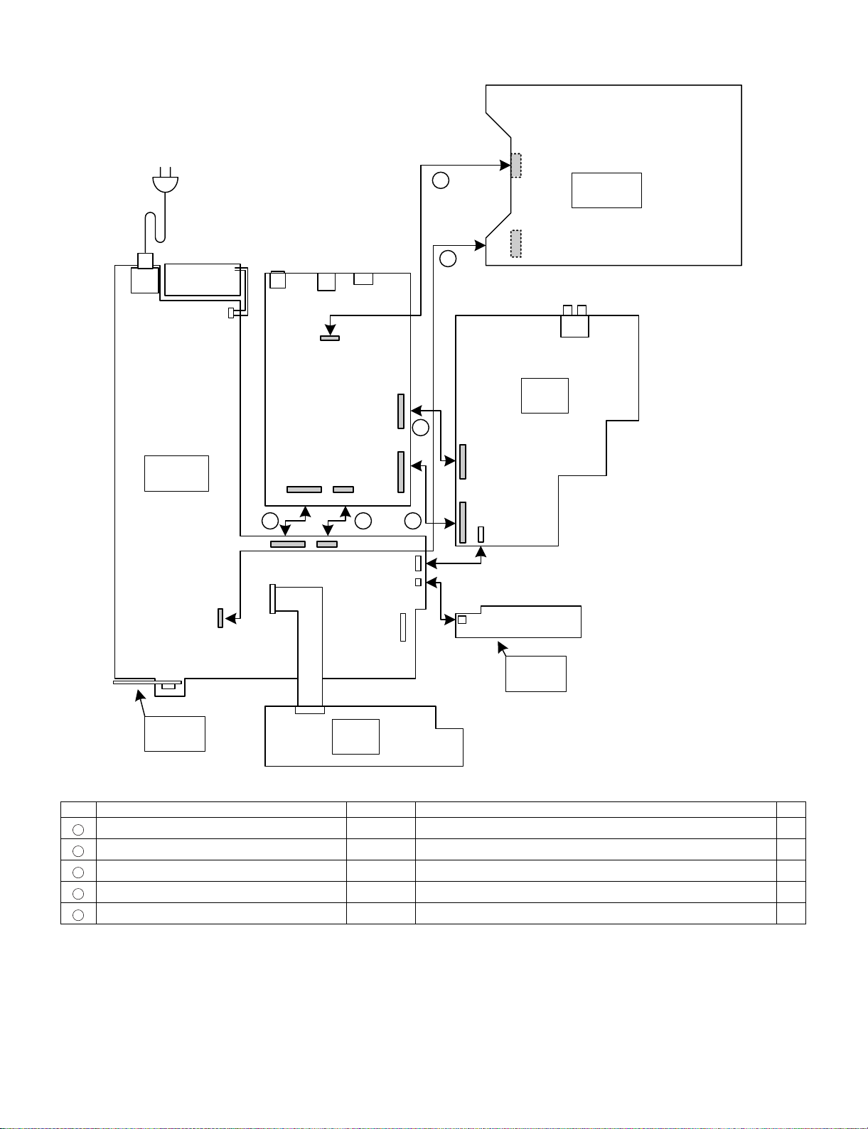
[2] EXTENSION CABLE CONNECTION DIAGRAM
BD-HP21U
㪪㪚㪐㪇㪈
㪧㪦㪮㪜㪩
㪧㪮㪙
㪝㪘㪥
㪚㪥㪐㪇㪉
㪚㪥㪏㪈㪇㪉
㪤㪘㪠㪥
㪧㪮㪙
㪪㪚㪐㪇㪇㪈 㪪㪚㪌㪍㪇㪋
㪚㪥㪐㪌㪇㪉 㪚㪥㪉㪌㪇㪈
㪜
㪙㪛
㪛㪩㪠㪭㪜
㪛
㪘㪭
㪧㪮㪙
㪪㪚㪌㪍㪇㪈
㪙
㪚㪥㪌㪍㪇㪈
㪚
㪘㪙
㪧㪉㪌㪇㪉
㪚㪥㪉㪊㪇㪈 㪚㪥㪉㪊㪇㪉
㪧㪉㪊㪇㪈
㪧㪉㪌㪇㪊
㪧㪉㪌㪇㪈
㪧㪈㪊㪇㪈
㪦㪧㪜㪄㪩
㪪㪚㪉㪌㪇㪈
㪚㪥㪐㪇㪈
㪚㪥㪉㪌㪇㪉
㪧㪮㪙
㪦㪧㪜㪄㪣
㪧㪮㪙
Parts Code Price Code Name/Description Pin
A
QCNW-E227WJPZ CL CN5601 <=> CN2301 23
B
QCNW-E229WJPZ DG SC5601 <=> CN2302, SC9001 <=> CN9502 15
C
QCNW-E231WJPZ DB SC5604 <=> CN2501 9
D
QCNW-E573WJPZ AP
E
- - SATA Cable ( Commercially available ) CN8102 <=> BD DRIVE 7
㪪㪚㪈㪈㪇㪈
㪣㪚㪛
㪧㪮㪙
CN901 <=> BD DRIVE 4
3 – 4
Page 12

BD-HP21U
㪨㪚㪥㪮㪄㪜㪉㪉㪎㪮㪡㪧㪱
㪘
㪚㪥㪌㪍㪇㪈㹤㪚㪥㪉㪊㪇㪈
㪬㫊㪼㪻㩷㫀㫅㩷㫋㪿㪼㩷㪸㫍㫆㪹㪼
㫆㫅㪼㩷㫇㫀㪼㪺㪼㪅㩷㩿㪉㪊㪧㫀㫅㪀
㪍㪇㪇
㪨㪚㪥㪮㪄㪜㪉㪉㪐㪮㪡㪧㪱
㪙
㪪㪚㪌㪍㪇㪈㹤㪚㪥㪉㪊㪇㪉
㪪㪚㪐㪇㪇㪈㹤㪚㪥㪐㪌㪇㪉
㪬㫊㪼㪻㩷㫀㫅㩷㫋㪿㪼㩷㪸㫍㫆㪹㪼
㫋㫎㫆㩷㫇㫀㪼㪺㪼㫊㪅㩷㩿㪈㪌㪧㫀㫅㪀
㪨㪚㪥㪮㪄㪜㪉㪊㪈㪮㪡㪧㪱
㪚
㪪㪚㪌㪍㪇㪋㹤㪚㪥㪉㪌㪇㪈
㪬㫊㪼㪻㩷㫀㫅㩷㫋㪿㪼㩷㪸㫍㫆㪹㪼
㫆㫅㪼㩷㫇㫀㪼㪺㪼㪅㩷㩿㪐㪧㫀㫅㪀
㪛
㪨㪚㪥㪮㪄㪜㪌㪎㪊㪮㪡㪧㪱
㪚㪥㪐㪇㪈㹤㪙㪛㩷㪛㪩㪠㪭㪜
㪬㫊㪼㪻㩷㫀㫅㩷㫋㪿㪼㩷㪸㫍㫆㪹㪼
㫆㫅㪼㩷㫇㫀㪼㪺㪼㪅㩷㩿㪋㪧㫀㫅㪀
㪪㪘㪫㪘㩷㪚㪸㪹㫃㪼㩷㩿㪚㫆㫄㫄㪼㫉㪺㫀㪸㫃㫃㫐㩷㪸㫍㪸㫀㫃㪸㪹㫃㪼㪀
㪜
㪍㪇㪇
㪍㪇㪇
㪌㪇㪇
㪚㪥㪏㪈㪇㪉㹤㪙㪛㩷㪛㪩㪠㪭㪜
㪬㫊㪼㪻㩷㫀㫅㩷㫋㪿㪼㩷㪸㫍㫆㪹㪼
㫆㫅㪼㩷㫇㫀㪼㪺㪼㪅㩷㩿㪎㪧㫀㫅㪀
3 – 5
Page 13

BD-HP21U
[3] IMPORTANT SERVICE NOTICE
1. To replace the Main CBA, perform the items 9 - 12 of [4] Upgrading and confirm the version: it is necessary to upgrade with a disc to the latest version if the CBA version is old.
2. The IC 7201 and IC8505 cannot be replaced because they have the BD-playback key already written. Accor dingly, the IC8502 that has the software written together with the IC8505 cannot be replaced either. Keep also in mind that the IC8503 cannot be replaced either because of the
model information on it.
3. After replacing the E2PROM for front-end software (IC2505), perform Menu - Miscellaneous Settings - Reset Settings.
4. The SPACE PWB (DUNTKE844TEV1) is used to adjust the drive height. In disassembling the set for overhauling or the like, be careful not to lose
it.
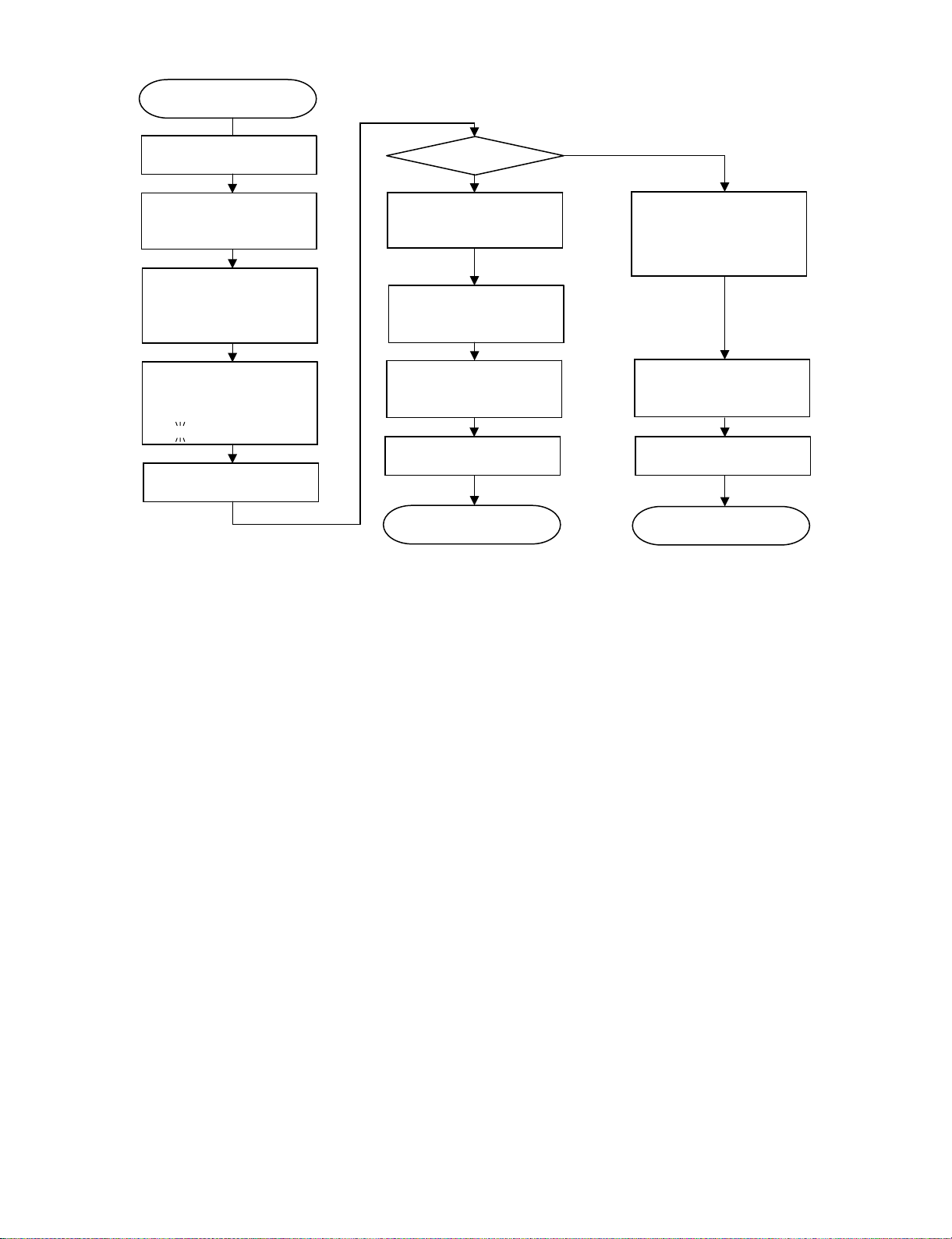
[4] UPGRADING
Consult with your Services Company as we cannot provide the upgrading software.
1. Press [Power] button to turn the switch on, then wait till the BD_LED changes from blinking to lit.
2. Press [Tray Open/Close] button to open the Tray, put the upgrade disc on the tray and close the tray.
3. The power automatically turns off. Then it turns on again and the upgrading with the disc will start.
4. During the upgrading, the mode indicator stays blinking in white as "V-up" message keeps blinking on LCD.
"NOW UPDATING DO NOT UNPLUG AC CORD" appears on the monitor screen.
And the version updating progress is expressed in %.
5. When upgrading with the disc is completed, the Tray automatically opens.
* If the front-end software was upgraded, the standby LED lights up halfway as well as the mode indicator starts blinking alternately in white and
blue.; the Tray will open after the upgrading is completed and the power will turn off. (Go to step 8.)
6. When the upgrading is completed, the following appears on the monitor screen.:
"SOFTWARE UPDATE IS COMPLETE"
If the version updating fails, "FAILED TO COMPLETE UPDATE RETRY SOFTWARE UPDATE" is displayed. Take out the disc, turn off the power
and take the procedure again starting from [1] above.
7. Remove the disc from the Tray and press any other button of the Main Unit than [Power], then the Tray will close and the power will automatically
turn off. (Confirm the power-off by stop of the Cooling Fan.)
* If [Power] button is pressed, the power will turn off with the Tray open.
8. Press [Power] button to turn the power on, then wait till the MODE INDICATOR changes from blinking to lit.
9. Press the [SETUP] button on the remote controller, and the menu screen shows up (if the wallpaper screen is used).
* There is no need to take this step, because just after the power is turned on, the menu screen shows up.
10.Select [SETTINGS] first and then [VERSION]. (Press the ENTER button.)
11.The version of the currently installed software appears on the monitor screen. Compare with the version of this updated software, make sure the
version is just the same. If the version id not updated, take the procedure again from Step [2].
12.Press [Power] button to turn the power off. (Confirm the power-off by stop of the cooling fan.)
NOTE: Do not unplug the AC cord during version updating.
3 – 6
Page 14
BD-HP21U
Start
Turn the power on.
Open the tray,
put the upgrade disc and
close the tray
The power automatically
turns off. Then, the power
turns on automatically and
the upgrading starts.
Monitor:
"NOW UPDATING
DO NOT UNPLUG AC CORD"
ex.
غغغع
غغ20%
The tray opens
automatically.
* The version updating cannot be made on the menu screen. Make the wallpaper onscreen.
Monitor: "CANNOT UPDATE. FINISH PLAYBACK OR EDIT AND SET A DISC"
Upgrading completed
Yes
Monitor:
"SOFTWARE UPDATE IS
COMPLETE"
Remove the disc and turn
the power off.
Turn the power on and
confirm the version.
Upgrading successful. Upgrading unsuccessful.
End
No
Monitor:
"FAILED TO COMPLETE
UPDATE
RETRY SOFTWARE
UPDATE"
Remove the disc and turn
the power off.
Restart
3 – 7
Page 15

BDHP21U
CHAPTER 4. BLOCK DIAGRAM
[1] MAIN BLOCK DIAGRAM
ServiceManual
㪚㪥㪌㪍㪇㪉
㪪㪧㪛㪠㪝㩷㪦㪬㪫
㪭㪟㪧㪞㪧㪈㪝㪌㪌㪫㪢㪭㪰
BD-HP21U
㪧㪩㪠㪤㪘㪩㪰
㪚㪦㪥㪫㪩㪦㪣
㪚㪠㪩㪚㪬㪠㪫
㪠㪚㪐㪇㪈
㪤㪩㪋㪇㪉㪇
㪦㪭㪜㪩㪭㪦㪣㪫㪘㪞㪜
㪧㪩㪦㪫㪜㪚㪫㪜㪩
㪪㪮
㪫㪩㪘㪥㪪
㪫㪐㪇㪈
㪮㪘㪉㪏㪈㪮㪡
㪝㪜㪜㪛㩷㪙㪘㪚㪢
㪚㪠㪩㪚㪬㪠㪫
㪪㪫㪘㪥㪛㪙㪰㩷㪚㪫㪣
㪚㪠㪩㪚㪬㪠㪫
㪝㪘㪥㩷㪩㪜㪞
㪦㪭㪧
㪘㪫㪶㪈㪋㪭
㪩㪜㪚㪫㪠㪝㪠㪜㪩
㪘㪫㪶㪐㪭
㪩㪜㪚㪫㪠㪝㪠㪜㪩
㪘㪫㪶㪌㪭
㪩㪜㪚㪫㪠㪝㪠㪜㪩
㪘㪫㪶㪄㪈㪉㪭
㪩㪜㪚㪫㪠㪝㪠㪜㪩
㪨㪐㪇㪈
㪉㪪㪛㪋㪍㪏
㪙㪛㪶㪈㪉㪭㩷㪩㪜㪞
㪨㪐㪇㪋
㪉㪪㪙㪈㪊㪋㪉
㪘㪫㪶㪐㪭㩷㩿㪫㫆㩷㪤㪘㪠㪥㩷㪧㪚㪙㪀
㪙㪛㪶㪌㪭㩷㪪㪮
㪨㪐㪈㪊
㪩㪪㪪㪇㪋㪇㪧
㪪㪬㪙㪶㪧㪚㪶㪌㪭㩷㪪㪮
㪨㪐㪌㪇㪈
㪩㪨㪇㪊㪌㪧
㪣㪦㪮㪶㪧㪦㪮㪜㪩㪶㪚㪫㪣
㪪㪬㪙㪶㪧㪚㪶㪄㪏㪭㩷㪪㪮
㪨㪐㪌㪇㪊
㪉㪪㪙㪈㪈㪊㪉㪨
㪧㫆㫎㪼㫉㩷㪙㪣㪦㪚㪢
㪫㫆㩷㪝㪘㪥㩷
㪚㪥㪐㪇㪉
㪝㪘㪥㪶㪎㪅㪌㪭
㪙㪛㪶㪈㪉㪭
㪙㪛㪶㪌㪭
㪪㪬㪙㪶㪧㪚㪶㪌㪭㩷㩿㪫㫆㩷㪤㪘㪠㪥㩷㪧㪚㪙㪀
㪪㪬㪙㪶㪧㪚㪶㪌㪭㩷㩿㪫㫆㩷㪘㪥㪘㪣㪦㪞㩷㪧㪚㪙㪀
㪘㪫㪶㪌㪭㩷㩿㪫㫆㩷㪤㪘㪠㪥㩷㪧㪚㪙㪀
㪘㪫㪶㪌㪭㩷㩿㪫㫆㩷㪘㪥㪘㪣㪦㪞㩷㪧㪚㪙㪀
㪪㪬㪙㪶㪧㪚㪶㪄㪏㪭㩷㩿㪫㫆㩷㪤㪘㪠㪥㩷㪧㪚㪙㪀
㪚㪥㪐㪇㪈
㪫㫆㩷㪙㪛㩷㪛㪩㪠㪭㪜
㪤㪸㫀㫅㩷㪙㫆㪸㫉㪻
㪠㪚㪏㪌㪇㪊
㪍㪋㪢 㪜㪉㪧
㪤㪉㪋㪚㪍㪋㪮㪥
㪠㪉㪚㪤㪶㪪㪚㪣㪃㩷㪠㪉㪚㪤㪶㪪㪛㪘
㪤㪘㪠㪥㪶㪰㪦㪬㪫
㪤㪘㪠㪥㪶㪧㪙㪦㪬㪫
㪤㪘㪠㪥㪶㪧㪩㪦㪬㪫
㪪㪬㪙㪶㪰㪦㪬㪫
㪪㪬㪙㪶㪚㪦㪬㪫
㪘㪬㪛㪠㪦
㪘㪬㪛㪠㪦
㪶㪌㪭
㪶㪄㪌㪭
㪠㪚㪌㪍㪇㪍
㪉㪺㪿㩷㪘㫌㪻㫀㫆㩷㪛㪘㪚
㪘㪢㪋㪊㪋㪇㪜㪫㩷
㪣㪆㪩
㪧㪚㪤
㪪㪚㪋㪉㪇㪈
㪘㪫㪶㪌㪭
㪨㪋㪉㪇㪈㪃㪋㪉㪇㪉
㪣㪜㪭㪜㪣㪚㪟㪘㪥㪞㪜
㪉㪪㪢㪌㪊㪍
㪠㪉㪚㪤㪶㪪㪚㪣㪃㩷㪠㪉㪚㪤㪶㪪㪛㪘
㪛㪛㪚
㪫㫏
㪟㪛㪤㪠㩷㪦㫌㫋
㪨㪪㪦㪚㪱㪘㪇㪎㪉㪮㪡㪱㪱㪨
㪠㪚㪋㪉㪇㪌
㪣㪚㪯㪈㪉㪌㪝㪫
㪘㪶㪌㪭
㪠㪚㪋㪉㪇㪍
㪧㪨㪈㪣㪘㪯㪐㪌
㪧㪤㪬㪫㪜㪈
㪧㪤㪬㪫㪜㪉
㪘㪬㪛㪤㪘㪠㪥㪤㪬㪫㪜
㪝㪠㪣㪶㪪㪜㪣
㪚㪪㪥
㪚㪚㪣㪢
㪚㪛㪫㪈
㪚㪪㪠
㪝㪄㫌㪚㪦㪥
㪩㪟㪄㪠㪯㪚㪈㪏㪉㪮㪡㪨㪈㪨
㪧㫆㫎㪼㫉㩷㪧㪮㪙
㪝㪩㪶㪚㪜㪚㪠㪥㪃㪝㪩㪶㪚㪜㪚㪦㪬㪫
㪧㪦㪮㪜㪩㪶㪝㪘㪠㪣
㪚㪙㪦㪦㪫
㪝㪣㪶㪙㪬㪪㪰
㪚㪦㪣㪛㪶㪩㪪㪫㩺
㪝㪩㪶㪫㪯㪛㪃㩷㪝㪩㪶㪩㪯㪛
㪛㪼㪹㫌㪾
㪪㪼㫉㫀㪸㫃
㪈㪋㪅㪊㪈㪏㪈㪏㪤㪟㫑
㪠㪚㪏㪎㪇㪉
㪚㫃㫆㪺㫂㩷㪞㪼㫅㪼㫉㪸㫋㫆㫉
㪧㪠㪍㪚㪋㪈㪇㪤
㪩㪟㪄㪠㪯㪚㪌㪈㪇㪮㪡㪨㪱㪰
㪠㪚㪎㪏㪇㪉㪃㪊
㪛㪛㪩㪉㩷㪪㪛㪩㪘㪤
㪈㪞㪹㫀㫋㪲㪍㪋㪤㬍㪈㪍㪹㫀㫋㪴
㪩㪟㪄㪠㪯㪚㪌㪍㪎㪮㪡㪨㪱㪨
㪛㪶㪈㪅㪏㪭
㪈㪇㪇㪤㪟㫑
㪪㪘㪚㪩㪜㪝㪧
㪆㪪㪘㪚㪩㪜㪝㪥
㪊㪊㪤㪟㫑
㪛㪶㪊㪅㪊㪭
㪬㪘㪩㪫㪇
㪬㪘㪩㪫㪈
㪜㪫㪟㪜㪩㪥㪜㪫
㪪㪘㪫㪘 㪚㪣㪢
㪧㪚㪠㩷㪚㪣㪢
㫉㪼㫊㪼㫋
㪉㪎㪤㪟㫑
㪠㪚㪎㪉㪇㪈
㪙㪛㩷㪧㫃㪸㫐㪼㫉㩷㪙㪜
㪜㪤㪤㪘㪊㪧
㪠㪯㪚㪋㪍㪎㪮㪡㪨㪱
㪞㪧㪠㪦
㪛㪛㪩㪉㩷㪪㪛㪩㪘㪤
㪈㪞㪹㫀㫋㪲㪍㪋㪤㬍㪈㪍㪹㫀㫋㪴
㪩㪟㪄㪠㪯㪚㪌㪍㪎㪮㪡㪨㪱㪨
㪛㪶㪈㪅㪏㪭
㪠㪚㪎㪏㪇㪋㪃㪌
㪠㪉㪚
㪟㪛㪤㪠
㪠㪉㪪
㪪㪧㪛㪠㪝
㪪㪘㪫㪘㪇
㪰㪆㪧㪹㪆㪧㫉
㪰㪆㪚
㪧㪚㪠
㪩㪦㪤㪆㪞㪠㪦
㪪㪙㪩㪪㪫
㪠㪚㪏㪌㪇㪌
㪥㪘㪥㪛 㪝㫃㪸㫊㪿
㪌㪈㪉㪤㪹㫀㫋㪲㪍㪋㪤㬍㪏㪹㫀㫋㪴
㪩㪟㪄㪠㪯㪚㪈㪋㪎㪮㪡㪨㪱㪨
㪛㪶㪊㪅㪊㪭 㪛㪶㪊㪅㪊㪭
㪮㪧
㪪㪙㪩㪪㪫
㪠㪚㪏㪌㪇㪉
㪥㫆㫉㩷㪝㫃㪸㫊㪿
㪈㪉㪏㪤㪹㫀㫋㪲㪈㪍㪤㬍㪏㪹㫀㫋㪴
㪭㪟㪠㪪㪉㪐㪞㪈㪉㪏㪧㪄㪈㪨
㪘㫅㪸㫃㫆㪾㩷㪙㫆㪸㫉㪻
㪙㪛㪆㪛㪭㪛㩷㪛㫉㫀㫍㪼㩷㪬㫅㫀㫋
㪚㪥㪏㪈㪇㪉
㪊㪇㪤㪟㫑
㪚㪥㪋㪏㪇㪉
㪠㪚㪋㪏㪇㪉
㪬㪪㪙㩷㪙㫉㫀㪻㪾㪼㩿㪉㪅㪇㪀
㪧㪛㪎㪉㪇㪈㪇㪉
㪧㪚㪠
㪛㪶㪊㪅㪊㪭
㪊㪊㪤㪟㫑
㪮㪧
㪬㪪㪙㩷㪺㫆㫅㫅㪼㪺㫋㫆㫉
4 – 1
Page 16

BD-HP21U
[2] ANALOG/LCD/OPERATION BLOCK DIAGRAM
㪦㫍㪼㫉㩷㪭㫆㫃㫋㪸㪾㪼㩷㪧㫉㫆㫋㪼㪺㫋㪼㫉
㪧㫉㫀㫄㪸㫉㫐
㪚㫆㫅㫋㫉㫆㫃
㪠㪚㪐㪇㪈
㪤㪩㪋㪇㪉㪇
㪪㫎㫀㫋㪺㪿㫀㫅㪾
㪫㫉㪸㫅㫊㪽㫆㫉㫄㪼㫉
㪮㪘㪉㪏㪈㪮㪡
㪝㪜㪜㪛㩷㪙㪘㪚㪢
㪪㪫㪘㪥㪛㪙㪰㩷㪚㪫㪣
㪧㪦㪮㪜㪩㩷㪧㪮㪙
㪘㪫㪶㪈㪋㪭
㪩㪼㪺㫋㫀㪽㫀㪼㫉
㪘㪫㪶㪐㪭
㪩㪼㪺㫋㫀㪽㫀㪼㫉
㪘㪫㪶㪌㪭
㪩㪼㪺㫋㫀㪽㫀㪼㫉
㪘㪫㪶㪄㪈㪉㪭
㪩㪼㪺㫋㫀㪽㫀㪼㫉
㪦㪭㪧
㪝㪘㪥㩷㪩㪜㪞
㪝㪘㪥㪶㪎㪅㪌㪭
㪨㪐㪇㪈
㪉㪪㪛㪋㪍㪏
㪨㪐㪇㪋
㪨㪐㪈㪊
㪨㪐㪌㪇㪈
㪩㪨㪇㪊㪌㪧
㪨㪐㪌㪇㪊
㪙㪛㪶㪈㪉㪭
㪙㪛㪶㪌㪭
㪙㪛㪶㪈㪉㪭㩷㪩㪜㪞
㪉㪪㪙㪈㪊㪋㪉
㪘㪫㪶㪐㪭㩷㩿㪫㫆㩷㪤㪘㪠㪥㩷㪧㪚㪙㪀
㪙㪛㪶㪌㪭㩷㪪㪮
㪩㪪㪪㪇㪋㪇㪧
㪪㪬㪙㪶㪧㪚㪶㪌㪭㩷㪪㪮
㪣㪦㪮㪶㪧㪦㪮㪜㪩㪶㪚㪫㪣
㪪㪬㪙㪶㪧㪚㪶㪄㪏㪭㩷㪪㪮
㪉㪪㪙㪈㪈㪊㪉㪨
㪫㫆㩷㪝㪘㪥㩷
㪫㪦
㪧㪦㪮㪜㪩㩷㪚㪠㪩㪚㪬㪠㪫
㪙㪣㪦㪚㪢
㪚㪥㪐㪇㪈
㪚㪥㪐㪇㪉
㪪㪬㪙㪶㪧㪚㪶㪌㪭㩷㩿㪫㫆㩷㪤㪘㪠㪥㩷㪧㪚㪙㪀
㪪㪬㪙㪶㪧㪚㪶㪌㪭㩷㩿㪫㫆㩷㪘㪥㪘㪣㪦㪞㩷㪧㪚㪙㪀
㪘㪫㪶㪌㪭㩷㩿㪫㫆㩷㪤㪘㪠㪥㩷㪧㪚㪙㪀
㪘㪫㪶㪌㪭㩷㩿㪫㫆㩷㪘㪥㪘㪣㪦㪞㩷㪧㪚㪙㪀
㪪㪬㪙㪶㪧㪚㪶㪄㪏㪭㩷㩿㪫㫆㩷㪤㪘㪠㪥㩷㪧㪚㪙㪀
㪫㫆㩷㪙㪛㩷㪛㪩㪠㪭㪜
㪈㪌㪧㪠㪥
㪙㩷㫋㫆㩷㪙
㪚㪥㪐㪌㪇㪉
㪤㪘㪠㪥㪶㪧㪄㪚㪦㪥㩿㪟㪀
㪛㪩㪠㪭㪜㪶㪧㪄㪚㪦㪥㩿㪟㪀
㪪㪬㪙㪶㪧㪚㪶㩿㪟㪀
㪝㪘㪥㪶㪛㪜㪫
㪣㪦㪮㪶㪧㪦㪮㪜㪩㪶㪚㪫㪣
㪪㪬㪙㪶㪪㪟㪦㪩㪫㪶㪛㪜㪫
㪤㪘㪠㪥㩷㪧㪮㪙
㪈㪌㪧㪠㪥
㪙㩷㫋㫆㩷㪙
㪪㪚㪐㪇㪇㪈
㪤㪘㪠㪥㪶㪧㪶㪚㪦㪥
㪦㪭㪧
㪘㪫㪶㪐㪭
㪘㪫㪶㪌㪭
㪪㪬㪙㪶㪧㪚㪶㪄㪏㪭
㪪㪬㪙㪶㪧㪚㪶㪌㪭
㪉㪊㪧㪠㪥
㪙㩷㫋㫆㩷㪙
㪚㪥㪉㪊㪇㪈
㪢㪜㪰㪶㪪㪫㪙㪰
㪝㪩㪶㪚㪜㪚㪶㪠㪥
㪝㪩㪶㪚㪜㪚㪶㪦㪬㪫㩷
㪛㪶㪞㪥㪛
㪝㪩㪦㪥㪫㪶㪩㪯㪛
㪝㪩㪦㪥㪫㪶㪫㪯㪛
㪚㪦㪣㪛㪶㪩㪪㪫㩷
㪝㪣㪶㪙㪬㪪㪰
㪧㪦㪮㪜㪩㪶㪝㪘㪠㪣
㪚㪙㪦㪦㪫
㪧㪦㪮㪜㪩㪶㪝㪘㪠㪣
㪠㪚㪉㪌㪇㪏
㪩㪜㪪㪜㪫
㪙㪬㪋㪏㪋㪍
㪠㪚㪉㪌㪇㪉
㪩㪜㪪㪜㪫
㪧㪪㪫㪊㪉㪉㪇
㪠㪚㪉㪌㪇㪍
㪘㪥㪛
㪫㪎㪪㪜㪫㪇㪏㪝
㪠㪚㪉㪌㪇㪉
㪜㪉㪧㪩㪦㪤㩷
㪙㪩㪉㪋㪣㪈㪍㪝
㪠㪚㪉㪌㪇㪈
㪩㪜㪪㪜㪫
㪙㪛㪌㪉㪊㪈
㪠㪉㪚
㪝㪩㪶㪚㪜㪚㪶㪦㪬㪫
㪝㪩㪶㪚㪜㪚㪶㪠㪥
㪝㪩㪦㪥㪫㪶㪩㪯㪛
㪝㪩㪦㪥㪫㪶㪫㪯㪛
㪚㪦㪣㪛㪶㪩㪪㪫
㪝㪣㪶㪙㪬㪪㪰
㪧㪦㪮㪜㪩㪶㪝㪘㪠㪣
㪚㪙㪦㪦㪫
㪠㪠㪚㪶㪪㪛㪘
㪠㪠㪚㪶㪪㪚㪣
㪤㪘㪠㪥㪶㪧㪦㪮
㪛㪩㪶㪧㪦㪮
㪪㪬㪙㪶㪧㪚㪶㩿㪟㪀
㪧㪦㪮㪜㪩㪶㪝㪘㪠㪣
㪝㪘㪥㪶㪛㪜㪫
㪣㪦㪮㪶㪧㪦㪮㪜㪩㪶㪚㪫㪣
㪪㪬㪙㪶㪪㪟㪦㪩㪫㪶㪛㪜㪫
㪩㪜㪪㪜㪫
㪩㪆㪚㪶㪧㪬㪣㪪㪜
㪢㪜㪰㪶㪪㪫㪙㪰
㪝㪩㪦㪥㪫㪶㪤㪠㪚㪦㪥
㪠㪯㪙㪏㪍㪎㪮㪡㪨㪱㪨
㪣㪚㪛㪶㪛㪘㪫㪘
㪣㪚㪛㪶㪚㪣㪢
㪣㪚㪛㪶㪚㪪
㪣㪚㪛㪶㪩㪪㪫
㪠㪚㪉㪌㪇㪋
㪙㪣㪶㪣㪜㪛
㪣㪜㪛㪶㪧㪦㪥
㪛㪶㪞㪥㪛
㪝㪠㪣㪶㪪㪜㪣
㪧㪤㪬㪫㪜㪉
㪣㪶㪦㪬㪫
㪩㪶㪦㪬㪫
㪝㪠㪣㪶㪪㪜㪣
㪧㪤㪬㪫㪜㪈
䌓䌙
䌓䌃
䌃䌖
㪤㪬㪫
㪭㪠㪛㪜㪦㩷㪙㫌㪽㪽㪼㫉
䌙
䌐䌂
䌐䌒
㪝㪠㪣
㪘㪬㪛㪤㪘㪠㪥㪤㪬㪫㪜
㪤㪬㪫
㪠㪚㪉㪉㪇㪋
㪟㪛㪆㪪㪛
㫎㫀㫋㪿㩷㪣㪧㪝
㪤㪤㪈㪎㪌㪎㪙㪟
㪘㪬㪛㪠㪦
㪤㪬㪫㪜
㪝㪶㪤㪬㪫㪜
䌓䌙
䌓䌃
䌃䌖
䌙
䌐䌂
䌐䌒
㪘㪶㪌㪭
㪡㪉㪋㪇㪈㪶㪉
㪨㪡㪘㪢㪣㪘㪇㪊㪐㪮㪡㪧㪱
㪡㪉㪋㪇㪈㪶㪈
㪨㪡㪘㪢㪣㪘㪇㪊㪐㪮㪡㪧㪱
㪈㪌㪧㪠㪥
㪙㩷㫋㫆㩷㪙
㪚㪥㪉㪊㪇㪉
㪝㪠㪣㪶㪪㪜㪣
㪛㪶㪞㪥㪛
㪧㪤㪬㪫㪜㪉
㪧㪤㪬㪫㪜㪈
㪘㪬㪛㪤㪘㪠㪥
㪤㪬㪫㪜
㪘㪶㪞㪥㪛
㪪㪬㪙㪶㪰㪦㪬㪫
㪘㪶㪞㪥㪛
㪪㪬㪙㪶㪚㪦㪬㪫
㪘㪶㪞㪥㪛
㪤㪘㪠㪥㪶㪰㪦㪬㪫
㪘㪶㪞㪥㪛
㪤㪘㪠㪥㪶㪧㪙㪦㪬㪫
㪘㪶㪞㪥㪛
㪤㪘㪠㪥㪶㪧㪩㪦㪬㪫
㪘㪶㪞㪥㪛
㪘㪬㪛㪶㪤㪘㪠㪥㪶㪣
㪘㪬㪛㪠㪦㪶㪞㪥㪛
㪘㪬㪛㪶㪤㪘㪠㪥㪶㪩
㪘㪬㪛㪠㪦㪶㪞㪥㪛
㪘㪭㩷㪧㪮㪙
㪧㪉㪊㪇㪈
㪌㪧㪠㪥
㪧㪣㪬㪞
㪧㪉㪌㪇㪉
㪘㪫㪶㪌㪭
㪝㪶㪤㪬㪫㪜
㪣㪜㪛㪶㪪㪫㪙㪰
㪣㪜㪛㪶㪛㪭㪛㪶㪧㪣㪘㪰
㪢㪜㪰㪶㪜㪡㪜㪚㪫
㪣㪜㪛㪶㪛㪭㪛㪶㪤㪦㪛㪜
㪣㪜㪛㪶㪙㪛㪶㪧㪣㪘㪰
㪣㪜㪛㪶㪙㪛㪶㪤㪦㪛㪜
㪪㪬㪙㪶㪧㪚㪌㪭
㪚㪥㪉㪌㪇㪉
㪋㪧㪠㪥
㪙㫋㫆㪙
㪚㪥㪈㪉㪇㪈
㪦㪧㪜㪩㪘㪫㪠㪦㪥㩿㪣㪜㪝㪫㪀㩷㪧㪮㪙
㪢㪜㪰㪶㪪㪫㪙㪰
㪧㪦㪮㪜㪩
㪩㪆㪚㪶㪧㪬㪣㪪㪜
㪢㪜㪰㪶㪪㪫㪙㪰
㪘㪫㪶㪌㪭
㪣㪚㪛㩷㪧㪮㪙
㪙㪣㪶㪣㪜㪛
㪩㪆㪚㪶㪧㪬㪣㪪㪜
㩿㪮㪟㪠㪫㪜㪀
㪚㪥㪉㪌㪇㪉
㪉㪈㪧㪠㪥㪝㪝㪚
㪪㪚㪈㪈㪇㪈
㪣㪚㪛㪶㪚㪣㪢
㪣㪚㪛㪶㪚㪪
㪣㪚㪛㪶㪛㪘㪫㪘
㪠㪚㪈㪈㪇㪈
㪣㪚㪛㩷㪛㪩㪠㪭㪜㪩
㪧㪫㪍㪌㪐㪍
㪣㪚㪛㪶㪩㪪㪫
㪪㪜㪞㪶㪈䌾㪈㪎
㪚㪦㪤㪈䌾㪊
㪘㪫㪶㪌㪭
㪣㪚㪛㪈㪈㪇㪈
㪣㪚㪛
㪩㪣㪚㪛㪛㪘㪇㪊㪐㪮㪡㪧㪱
㪦㪧㪜㪩㪘㪫㪠㪦㪥㩿㪩㪠㪞㪟㪫㪀㩷㪧㪮㪙
㪣㪜㪛㪶㪧㪦㪥
㪣㪜㪛㪶㪪㪫㪙㪰
㪣㪜㪛㪶㪙㪛㪶㪧㪣㪘㪰㩷㩿㪙㫃㫌㪼㪀
㪣㪜㪛㪶㪙㪛㪶㪤㪦㪛㪜㩷㩿㪮㪿㫀㫋㪼㪀
㪧㪉㪌㪇㪈
㪉㪧㪠㪥
㪧㪣㪬㪞
㪪㪚㪈㪊㪇㪈
㪢㪜㪰㪶㪜㪡㪚㪫
㪜㪡㪜㪚㪫
4 – 2
Page 17

BDHP21U
CHAPTER 5. SCHEMATIC DIAGRAMS
[1] MAIN (1) CIRCUIT SCHEMATIC DIAGRAM
J
I
H
BD-HP21U
ServiceManual
G
F
E
D
C
B
A
123456789
10 11 12 13 14 15 16 17 18 19 20 21
5 – 1
Page 18
BD-HP21U
[2] MAIN (2) CIRCUIT SCHEMATIC DIAGRAM
J
I
H
G
F
E
D
C
B
A
123456789
10 11 12 13 14 15 16 17 18 19 20 21
5 – 2
Page 19

[3] MAIN (3) CIRCUIT SCHEMATIC DIAGRAM
J
I
H
G
BD-HP21U
F
E
D
C
B
A
123456789
10 11 12 13 14 15 16 17 18 19 20 21
5 – 3
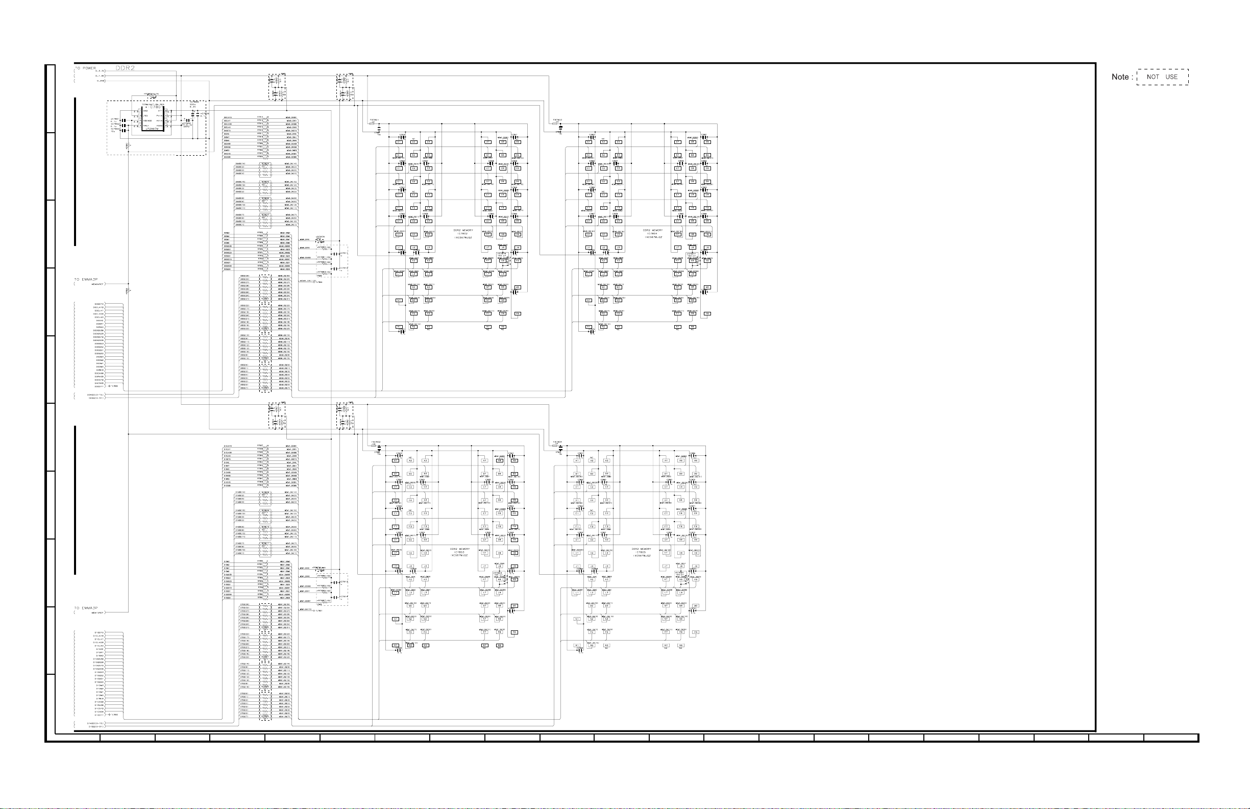
Page 20

BD-HP21U
[4] MAIN (4) CIRCUIT SCHEMATIC DIAGRAM
J
I
H
G
F
E
D
C
B
A
123456789
10 11 12 13 14 15 16 17 18 19 20 21
5 – 4
Page 21

[5] MAIN (5) CIRCUIT SCHEMATIC DIAGRAM
J
I
H
G
BD-HP21U
F
E
D
C
B
A
123456789
10 11 12 13 14 15 16 17 18 19 20 21
5 – 5
Page 22

BD-HP21U
[6] MAIN (6) CIRCUIT SCHEMATIC DIAGRAM
J
I
H
G
F
E
D
C
B
A
123456789
10 11 12 13 14 15 16 17 18 19 20 21
5 – 6
Page 23

[7] MAIN (7) CIRCUIT SCHEMATIC DIAGRAM
J
I
H
G
BD-HP21U
F
E
D
C
B
A
123456789
10 11 12 13 14 15 16 17 18 19 20 21
5 – 7
Page 24

BD-HP21U
[8] MAIN (8) CIRCUIT SCHEMATIC DIAGRAM
J
I
H
G
F
E
D
C
B
A
123456789
10 11 12 13 14 15 16 17 18 19 20 21
5 – 8
Page 25

[9] MAIN (9) CIRCUIT SCHEMATIC DIAGRAM
J
I
H
G
BD-HP21U
F
E
D
C
B
A
123456789
10 11 12 13 14 15 16 17 18 19 20 21
5 – 9
Page 26

BD-HP21U
[10] MAIN (10) CIRCUIT SCHEMATIC DIAGRAM
J
I
H
G
F
E
D
C
B
A
123456789
10 11 12 13 14 15 16 17 18 19 20 21
5 – 10
Page 27

[1 1] ANALOG CIRCUIT SCHEMATIC DIAGRAM
J
I
H
G
BD-HP21U
F
E
D
C
B
A
123456789
10 11 12 13 14 15 16 17 18 19 20 21
5 – 11
Page 28
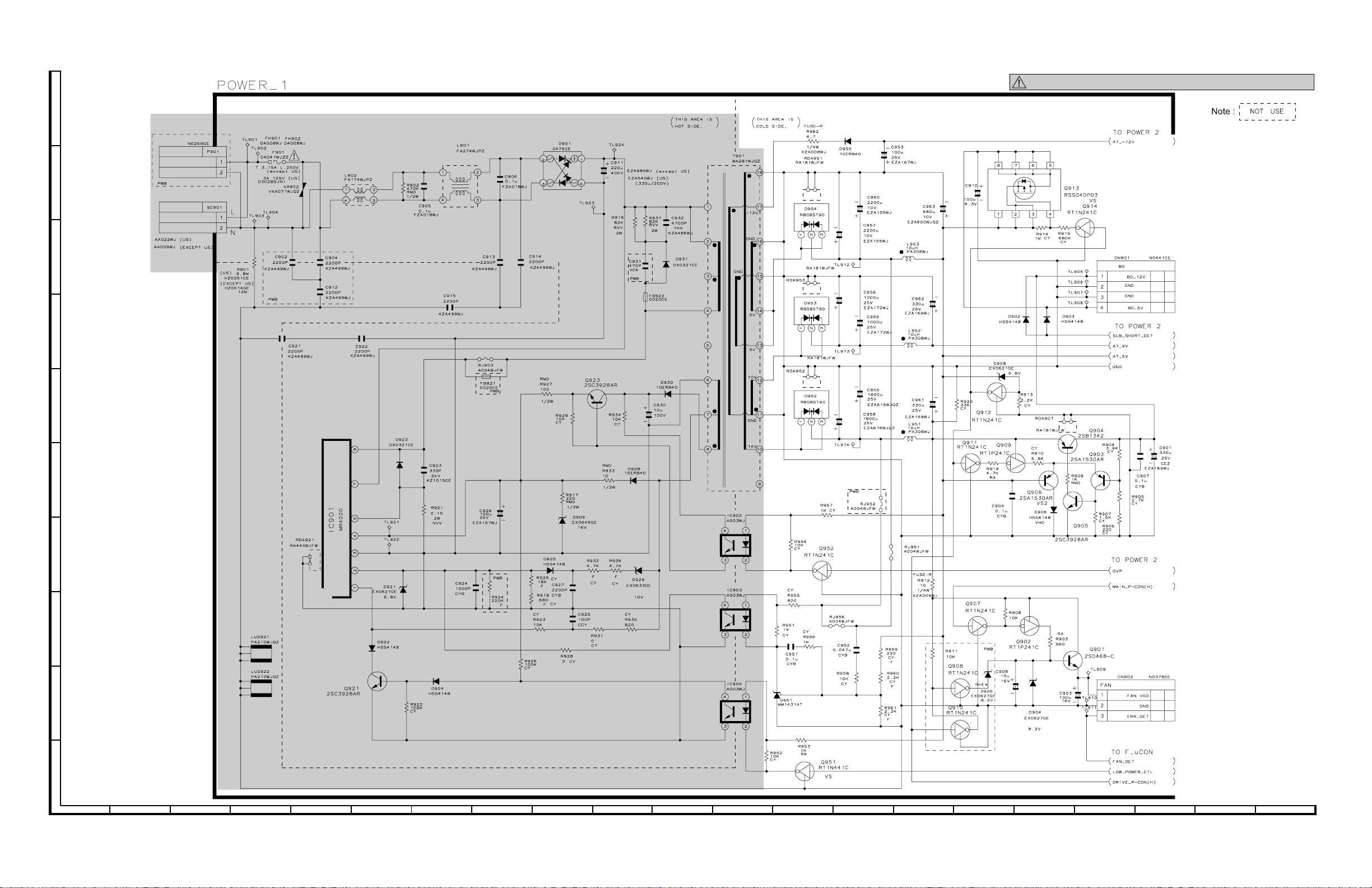
BD-HP21U
[12] POWER (1) CIRCUIT SCHEMATIC DIAGRAM
J
I
H
G
AND SHADED COMPONENTS=SAFETY RELATED PARTS
F
E
D
C
B
A
123456789
10 11 12 13 14 15 16 17 18 19 20 21
5 – 12
Page 29

[13] POWER (2) CIRCUIT SCHEMATIC DIAGRAM
J
I
H
G
BD-HP21U
F
E
D
C
B
A
123456789
10 11 12 13 14 15 16 17 18 19 20 21
5 – 13
Page 30
BD-HP21U
[14] POWER (3) CIRCUIT SCHEMATIC DIAGRAM
J
I
H
G
F
E
D
C
B
A
123456789
10 11 12 13 14 15 16 17 18 19 20 21
5 – 14
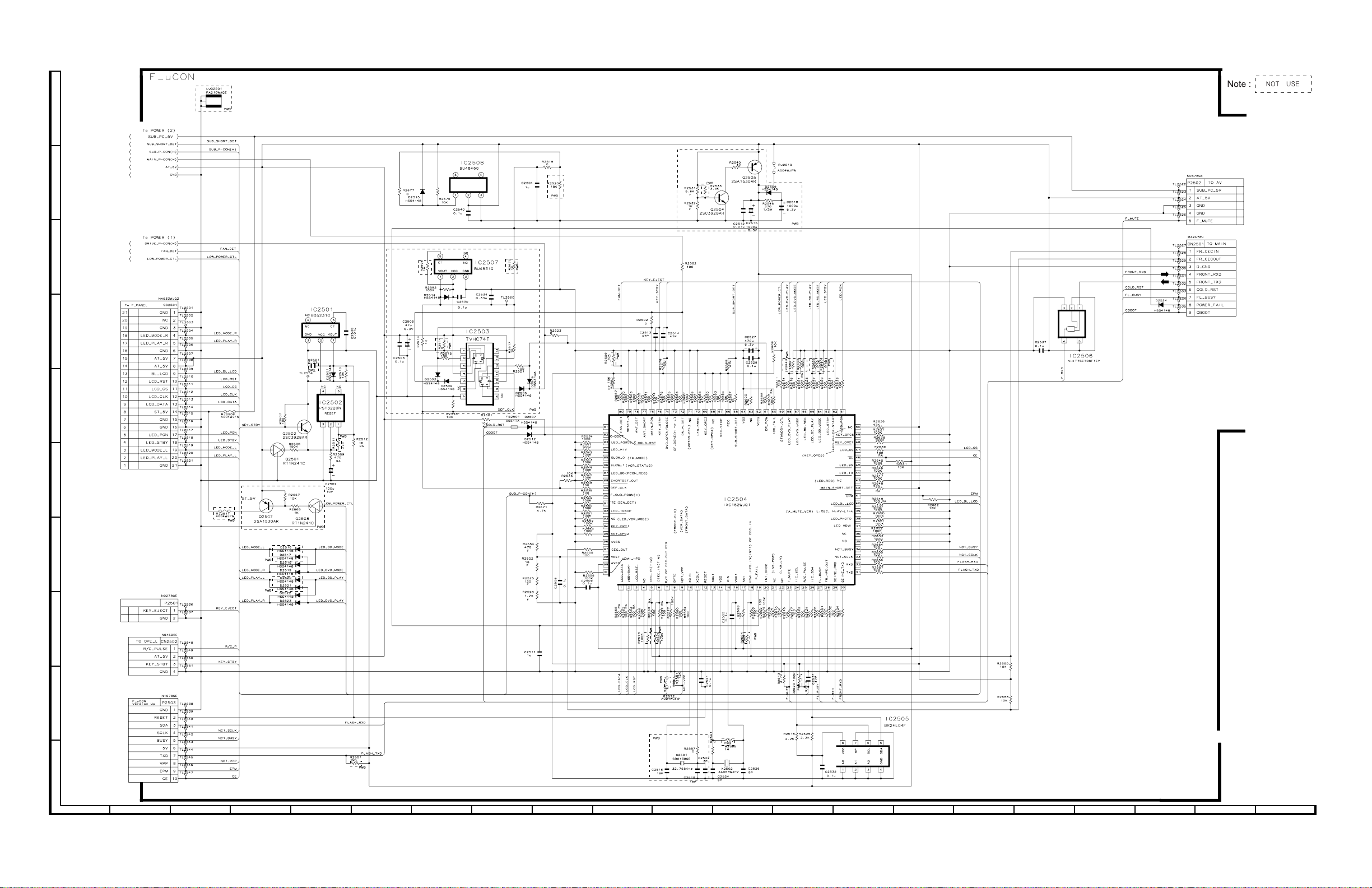
Page 31

[15] OPERATON CIRCUIT SCHEMATIC DIAGRAM
J
I
H
G
BD-HP21U
F
E
D
C
B
A
123456789
10 11 12 13 14 15 16 17 18 19 20 21
5 – 15
Page 32

BD-HP21U
J
I
H
G
F
E
D
C
B
A
123456789
10 11 12 13 14 15 16 17 18 19 20 21
5 – 16
Page 33

[16] LCD CIRCUIT SCHEMATIC DIAGRAM
J
I
H
G
BD-HP21U
F
E
D
C
B
A
123456789
10 11 12 13 14 15 16 17 18 19 20 21
5 – 17
Page 34

BD-HP21U
BDHP21U
CHAPTER 6. PRINTED WIRING BOARD ASSEMBLIES
[1] MAIN PWB
Side-A Symbol
J
I
H
ServiceManual
G
F
E
D
C
B
A
123456789
10 11 12 13 14 15 16 17 18 19 20 21
6 – 1
Page 35

Side-A
J
I
H
G
BD-HP21U
F
E
D
C
B
A
123456789
10 11 12 13 14 15 16 17 18 19 20 21
6 – 2
Page 36

BD-HP21U
Side-B Symbol
J
I
H
G
F
E
D
C
B
A
123456789
10 11 12 13 14 15 16 17 18 19 20 21
6 – 3
Page 37

Side-B
J
I
H
G
BD-HP21U
F
E
D
C
B
A
123456789
10 11 12 13 14 15 16 17 18 19 20 21
6 – 4
Page 38

BD-HP21U
[2] ANALOG PWB
Side-A
J
I
H
G
F
E
D
C
B
A
123456789
10 11 12 13 14 15 16 17 18 19 20 21
6 – 5
Page 39

J
I
H
G
BD-HP21U
Side-B
F
E
D
C
B
A
123456789
10 11 12 13 14 15 16 17 18 19 20 21
6 – 6
Page 40

BD-HP21U
[3] POWER PWB
Side-A
J
I
H
G
F
E
D
C
B
A
123456789
10 11 12 13 14 15 16 17 18 19 20 21
6 – 7
Page 41

J
I
H
G
BD-HP21U
Side-B
F
E
D
C
B
A
123456789
10 11 12 13 14 15 16 17 18 19 20 21
6 – 8
Page 42

BD-HP21U
[4] OPERATION-L PWB
J
Side-A Side-B
I
H
G
F
E
D
C
B
A
123456789
10 11 12 13 14 15 16 17 18 19 20 21
6 – 9
Page 43

[5] OPERATION-R PWB
Side-A
J
I
H
G
BD-HP21U
F
Side-B
E
D
C
B
A
123456789
10 11 12 13 14 15 16 17 18 19 20 21
6 – 10
Page 44
BD-HP21U
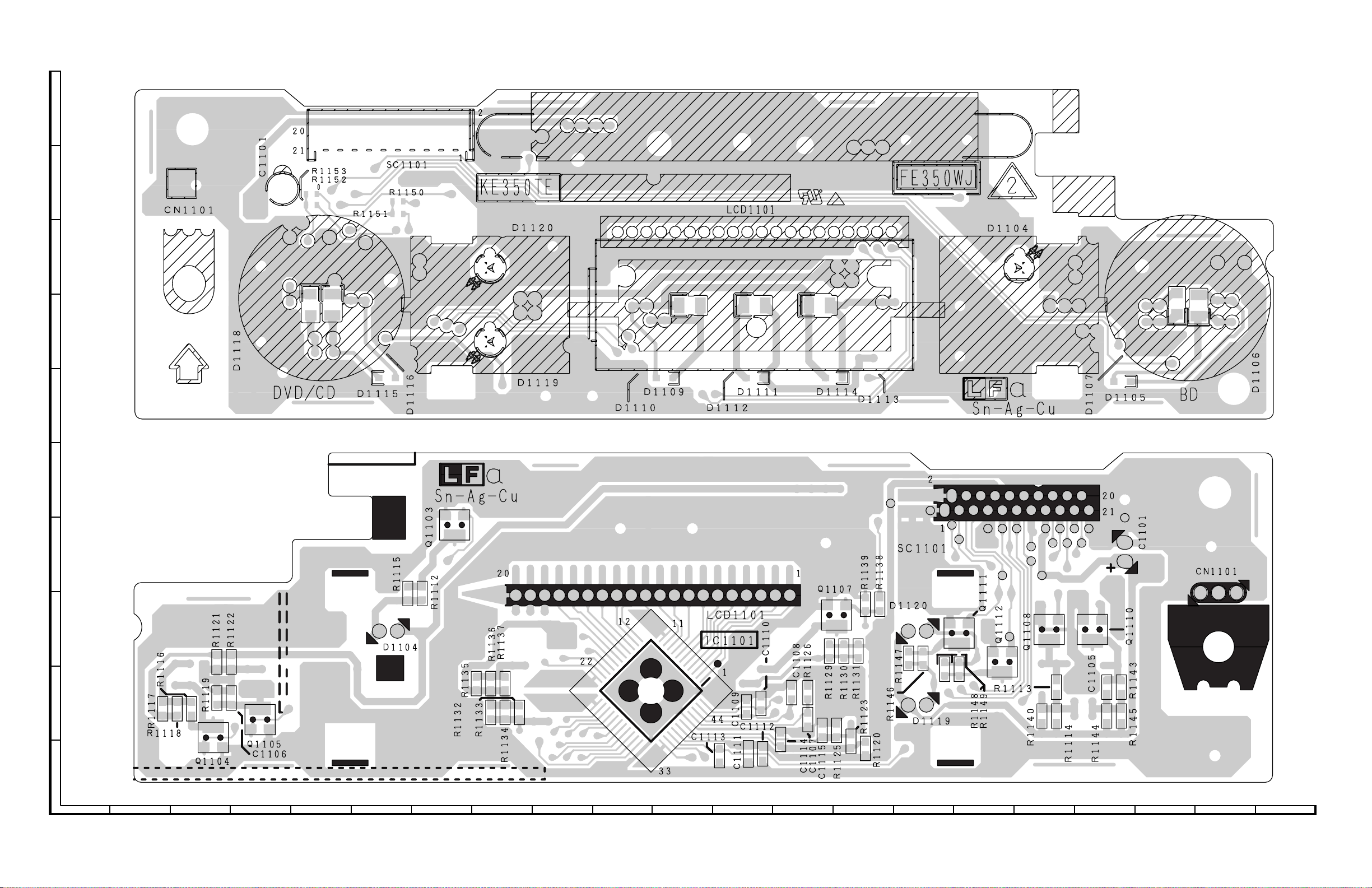
[6] LCD PWB
J
I
H
G
Side-A
F
Side-B
E
D
C
B
A
123456789
10 11 12 13 14 15 16 17 18 19 20 21
6 – 11
Page 45
[7] SPACER PWB
J
I
H
G
BD-HP21U
F
E
D
C
B
A
123456789
10 11 12 13 14 15 16 17 18 19 20 21
6 – 12
Page 46

BD-HP21U
- MEMO -
6 – 13
Page 47
PartsGuide
BD-HP21U
PARTS GUIDE
No. S88M8BDHP21U/
BLU-RAY DISC PLAYER
CONTENTS
[1] PRINTED WIRING BOARD
ASSEMBLIES
[2] DSETV0192TEZM (MAIN Unit)
[3] DUNTKE841TEV1 (ANALOG Unit)
[4] DUNTKE840TEV1 (POWER Unit)
[5] DUNTKE842TEV1 (OPERATION-L
Unit)
[6] DUNTKE843TEV1 (OPERATION-R
Unit)
MODEL
[7] DUNTKE350TE6D (LCD Unit)
[8] CABINET PARTS
[9] FRONT PANEL PARTS
[10] PACKING PARTS (NOT
[11] SUPPLIED ACCESSORIES
[12] SERVICE JIG
BD-HP21U
REPLACEMENT ITEM)
Parts marked with " " are important for maintaining the safety of the set. Be sure to replace these
parts with specified ones for maintaining the safety and performance of the set.
This document has been published to be used
for after sales service only.
The contents are subject to change without notice.
Page 48

BD-HP21U
NO. PARTS CODE
PRICE
RANK
NEW
MARK
PART
DELIVERY
[1] PRINTED WIRING BOARD ASSEMBLIES
N DMECDA012TEV1 CH N V BD-RH2 Drive Unit
N DSETV0192TEZM CA N V MAIN Unit
N DUNTKE841TEV1 AT N V ANALOG Unit
N DUNTKE840TEV1 BK N V POWER Unit
N DUNTKE842TEV1 AL N V OPERATION-L Unit
N DUNTKE843TEV1 AH N V OPERATION-R Unit
N DUNTKE844TEV1 AH N V SPACER Unit
N DUNTKE350TE6D BE N V LCD Unit
[2] DSETV0192TEZM (MAIN Unit)
C4201 VCKYCY1AB105KY AB V 1 10V Ceramic
C4202 VCKYCY1AB105KY AB V 1 10V Ceramic
C4212 RC-KZA117WJZZY AC V CAPACITOR
C4222 VCKYCY1HB103KY AA V 0.01 50V Ceramic
C4223 VCKYCY1AB105KY AB V 1 10V Ceramic
C4224 VCKYCY1HB103KY AA V 0.01 50V Ceramic
C4225 VCKYCY1AB105KY AB V 1 10V Ceramic
C4226 VCKYCY1CB104KY AB V 0.1 16V Ceramic
C4232 VCKYCY1AB105KY AB V 1 10V Ceramic
C4801 VCKYCY1HB102KY AA V 1000p 50V Ceramic
C4802 RC-KZA110WJZZY AD V CAPACITOR
C4803 RC-KZA214WJZZY AD V CAPACITOR
C4805 VCCCCY1HH471JY AA V 470p 50V Ceramic
C4806 VCCCCY1HH101JY AA V 100p 50V Ceramic
C4808 RC-KZA343WJPZY AB V CAPACITOR
C4809 RC-KZA195WJZZY AB V CAPACITOR
C4810 VCKYCY1CB104KY AB V 0.1 16V Ceramic
C4811 VCKYCY1CB104KY AB V 0.1 16V Ceramic
C4812 VCKYCY1CB104KY AB V 0.1 16V Ceramic
C4813 RC-KZA195WJZZY AB V CAPACITOR
C4814 RC-KZA195WJZZY AB V CAPACITOR
C4815 VCKYCY1HB103KY AA V 0.01 50V Ceramic
C4816 RC-KZA195WJZZY AB V CAPACITOR
C4817 VCKYCY1CB104KY AB V 0.1 16V Ceramic
C4818 VCKYCY1CB104KY AB V 0.1 16V Ceramic
C4821 VCKYCY1CB104KY AB V 0.1 16V Ceramic
C4823 VCCCCY1HH8R0DY AA V 80p 50V Ceramic
C4824 VCCCCY1HH8R0DY AA V 80p 50V Ceramic
C4825 VCKYCY1CB104KY AB V 0.1 16V Ceramic
C4826 VCKYCY1CB104KY AB V 0.1 16V Ceramic
C4827 VCKYCY1CB104KY AB V 0.1 16V Ceramic
C4828 VCKYCY1CB104KY AB V 0.1 16V Ceramic
C4829 VCKYCY1CB104KY AB V 0.1 16V Ceramic
C4830 VCKYCY1CB104KY AB V
C4831 VCKYCY1CB104KY AB V 0.1 16V Ceramic
C4832 RC-KZA195WJZZY AB V CAPACITOR
C4833 VCKYCY1CB104KY AB V 0.1 16V Ceramic
C4834 VCKYCY1CB104KY AB V 0.1 16V Ceramic
C4835 VCKYCY1AB105KY AB V 1 10V Ceramic
C4836 VCKYCY1HB104KY AA V 0.1 50V Ceramic
C4837 VCEASH0JN227MY AC V 220 6.3V Electrolytic
C5608 RC-KZA117WJZZY AC V CAPACITOR
C5609 VCKYCY1CB104KY AB V 0.1 16V Ceramic
C5611 RC-KZA117WJZZY AC V CAPACITOR
C5613 VCKYCY1HB103KY AA V 0.01 50V Ceramic
C5614 VCKYCY1CB104KY AB V 0.1 16V Ceramic
C5618 VCEAPF1CW106MY AB V 10 16V Electrolytic
C5619 VCEAPF1CW106MY AB V 10 16V Electrolytic
C5620 VCKYCY1CB104KY AB V 0.1 16V Ceramic
C5621 VCKYCY1CB104KY AB V 0.1 16V Ceramic
C5622 VCEAPF0JW107MY AC V 100 6.3V Electrolytic
C5626 VCKYCY1CB104KY AB V 0.1 16V Ceramic
C5630 VCCCCY1HH330JY AA V 33p 50V Ceramic
C7201 VCKYCZ1EB103KY AA V 0.01 25V Ceramic
C7202 VCCCCY1HH330JY AA V 33p 50V Ceramic
C7203 VCKYCZ1EB103KY AA V 0.01 25V Ceramic
C7204 VCKYCZ1AB104KY AB V 0.1 10V Ceramic
C7205 VCKYCZ1AB104KY AB V 0.1 10V Ceramic
C7206 RC-KZA195WJZZY AB V CAPACITOR
C7207 VCKYCZ1EB103KY AA V 0.01 25V Ceramic
C7209 VCKYCZ1AB104KY AB V 0.1 10V Ceramic
C7210 VCKYCZ1EB103KY AA V 0.01 25V Ceramic
C7211 VCKYCZ1AB104KY AB V 0.1 10V Ceramic
C7212 VCKYCZ1EB103KY AA V 0.01 25V Ceramic
C7213 VCKYCZ1AB104KY AB V 0.1 10V Ceramic
C7215 VCKYCZ1AB104KY AB V 0.1 10V Ceramic
C7216 VCKYCZ1AB104KY AB V 0.1 10V Ceramic
C7218
C7220 VCKYCZ1AB104KY AB V 0.1 10V Ceramic
C7222 VCKYCZ1AB104KY AB V 0.1 10V Ceramic
C7224 VCKYCZ1AB104KY AB V 0.1 10V Ceramic
C7225 VCKYCZ1AB104KY AB V 0.1 10V Ceramic
C7228 VCKYCZ1AB104KY AB V 0.1 10V Ceramic
C7229 VCKYCZ1AB104KY AB V 0.1 10V Ceramic
C7230 VCKYCZ1AB104KY AB V 0.1 10V Ceramic
VCKYCZ1AB104KY AB V 0.1 10V Ceramic
0.1 16V Ceramic
DESCRIPTION
2
Page 49

BD-HP21U
NO. PARTS CODE
PRICE
RANK
NEW
MARK
PART
DELIVERY
[2] DSETV0192TEZM (MAIN Unit)
C7233 VCKYCZ1AB104KY AB V 0.1 10V Ceramic
C7234 VCKYCZ1AB104KY AB V 0.1 10V Ceramic
C7235 VCKYCZ1AB104KY AB V 0.1 10V Ceramic
C7236 VCKYCZ1EB103KY AA V 0.01 25V Ceramic
C7237 VCKYCZ1AB104KY AB V 0.1 10V Ceramic
C7238 VCKYCZ1AB104KY AB V 0.1 10V Ceramic
C7239 VCKYCZ1EB103KY AA V 0.01 25V Ceramic
C7240 VCKYCZ1AB104KY AB V 0.1 10V Ceramic
C7241 VCKYCZ1AB104KY AB V 0.1 10V Ceramic
C7242 VCKYCZ1AB104KY AB V 0.1 10V Ceramic
C7243 VCKYCZ1EB103KY AA V 0.01 25V Ceramic
C7244 VCKYCZ1EB103KY AA V 0.01 25V Ceramic
C7245 VCKYCZ1AB104KY AB V 0.1 10V Ceramic
C7246 VCCCCY1HH330JY AA V 33p 50V Ceramic
C7247 VCKYCZ1AB104KY AB V 0.1 10V Ceramic
C7249 VCKYCZ1AB104KY AB V 0.1 10V Ceramic
C7250 VCKYCZ1AB104KY AB V 0.1 10V Ceramic
C7252 VCKYCZ1AB104KY AB V 0.1 10V Ceramic
C7253 VCKYCZ1AB104KY AB V 0.1 10V Ceramic
C7254 VCKYCZ1EB103KY AA V 0.01 25V Ceramic
C7255 VCCCCY1HH330JY AA V 33p 50V Ceramic
C7256 VCKYCZ1AB104KY AB V 0.1 10V Ceramic
C7257 VCKYCY1AB105KY AB V 1 10V Ceramic
C7258 VCKYCZ1EB103KY AA V 0.01 25V Ceramic
C7259 VCKYCY1AB105KY AB V 1 10V Ceramic
C7260 VCKYCZ1EB103KY AA V 0.01 25V Ceramic
C7262 VCKYCZ1AB104KY AB V 0.1 10V Ceramic
C7263 VCKYCY1AB105KY AB V 1 10V Ceramic
C7265 VCKYCZ1AB104KY AB V 0.1 10V Ceramic
C7267 VCKYCZ1AB104KY AB V 0.1 10V Ceramic
C7268 VCKYCZ1AB104KY AB V 0.1 10V Ceramic
C7269 VCKYCZ1AB104KY AB V 0.1 10V Ceramic
C7270 VCKYCZ1AB104KY AB V 0.1 10V Ceramic
C7271 VCKYCZ1AB104KY AB V
C7272 VCAAPE0JJ227MY AE V 220 6.3V Electrolytic
C7273 VCKYCZ1EB103KY AA V 0.01 25V Ceramic
C7274 VCKYCZ1EB103KY AA V 0.01 25V Ceramic
C7278 VCKYCZ1AB104KY AB V 0.1 10V Ceramic
C7279 VCKYCZ1AB104KY AB V 0.1 10V Ceramic
C7281 VCKYCZ1AB104KY AB V 0.1 10V Ceramic
C7282 VCKYCZ1AB104KY AB V 0.1 10V Ceramic
C7283 VCKYCZ1AB104KY AB V 0.1 10V Ceramic
C7284 VCKYCZ1AB104KY AB V 0.1 10V Ceramic
C7285 VCKYCZ1AB104KY AB V 0.1 10V Ceramic
C7287 VCKYCZ1AB104KY AB V 0.1 10V Ceramic
C7288 VCKYCZ1AB104KY AB V 0.1 10V Ceramic
C7289 VCKYCZ1AB104KY AB V 0.1 10V Ceramic
C7290 VCKYCZ1AB104KY AB V 0.1 10V Ceramic
C7292 VCKYCZ1AB104KY AB V 0.1 10V Ceramic
C7293 VCKYCZ1AB104KY AB V 0.1 10V Ceramic
C7294 RC-KZA195WJZZY AB V CAPACITOR
C7295 VCKYCZ1AB104KY AB V 0.1 10V Ceramic
C7296 RC-KZA195WJZZY AB V CAPACITOR
C7297 VCKYCZ1AB104KY AB V 0.1 10V Ceramic
C7298 VCKYCZ1AB104KY AB V 0.1 10V Ceramic
C7299 VCKYCZ1AB104KY AB V 0.1 10V Ceramic
C7300 VCKYCZ1AB104KY AB V 0.1 10V Ceramic
C7301 VCKYCZ1AB104KY AB V 0.1 10V Ceramic
C7303 VCKYCZ1AB104KY AB V 0.1 10V Ceramic
C7304 VCKYCY1AB105KY AB V 1 10V Ceramic
C7305 VCKYCY1AB105KY AB V 1 10V Ceramic
C7306 RC-KZA195WJZZY AB V CAPACITOR
C7307 VCCCCY1HH4R0CY AA V 40p 50V Ceramic
C7308 VCCCCY1HH4R0CY AA V 40p 50V Ceramic
C7309 VCKYCY1AB105KY AB V 1 10V Ceramic
C7310 VCKYCZ1AB104KY AB V 0.1 10V Ceramic
C7311 RC-KZA195WJZZY AB V CAPACITOR
C7312
C7317 VCKYCY1AB105KY AB V 1 10V Ceramic
C7318 VCKYCZ1AB104KY AB V 0.1 10V Ceramic
C7319 VCKYCZ1AB104KY AB V 0.1 10V Ceramic
C7320 VCKYCY1AB105KY AB V 1 10V Ceramic
C7322 RC-KZA195WJZZY AB V CAPACITOR
C7323 RC-KZA195WJZZY AB V CAPACITOR
C7324 RC-KZA195WJZZY AB V CAPACITOR
C7325 RC-KZA195WJZZY AB V CAPACITOR
C7326 VCKYCY1AB105KY AB V 1 10V Ceramic
C7327 VCKYCZ1AB104KY AB V 0.1 10V Ceramic
C7328 RC-KZA195WJZZY AB V CAPACITOR
C7329 RC-KZA195WJZZY AB V CAPACITOR
C7330 VCKYCY1AB105KY AB V 1 10V Ceramic
C7333 VCKYCZ1AB104KY AB V 0.1 10V Ceramic
C7336 VCKYCY1AB105KY AB V 1 10V Ceramic
C7337 VCKYCZ1AB104KY AB V 0.1 10V Ceramic
C7339 VCKYCZ1AB104KY AB V 0.1 10V Ceramic
VCKYCY1AB105KY AB V 1 10V Ceramic
0.1 10V Ceramic
DESCRIPTION
3
Page 50

BD-HP21U
NO. PARTS CODE
PRICE
RANK
NEW
MARK
PART
DELIVERY
[2] DSETV0192TEZM (MAIN Unit)
C7340 VCKYCZ1AB104KY AB V 0.1 10V Ceramic
C7341 VCKYCZ1AB104KY AB V 0.1 10V Ceramic
C7342 VCKYCZ1AB104KY AB V 0.1 10V Ceramic
C7343 VCKYCZ1AB104KY AB V 0.1 10V Ceramic
C7344 VCKYCZ1AB104KY AB V 0.1 10V Ceramic
C7345 RC-KZA195WJZZY AB V CAPACITOR
C7346 RC-KZA195WJZZY AB V CAPACITOR
C7347 VCKYCZ1EB103KY AA V 0.01 25V Ceramic
C7348 VCKYCZ1EB103KY AA V 0.01 25V Ceramic
C7349 VCKYCZ1EB103KY AA V 0.01 25V Ceramic
C7350 VCKYCZ1EB103KY AA V 0.01 25V Ceramic
C7351 VCKYCZ1EB103KY AA V 0.01 25V Ceramic
C7352 VCKYCZ1EB103KY AA V 0.01 25V Ceramic
C7353 VCKYCZ1EB103KY AA V 0.01 25V Ceramic
C7354 VCKYCZ1AB104KY AB V 0.1 10V Ceramic
C7355 VCKYCZ1AB104KY AB V 0.1 10V Ceramic
C7356 VCKYCZ1EB103KY AA V 0.01 25V Ceramic
C7357 VCKYCZ1EB103KY AA V 0.01 25V Ceramic
C7358 VCKYCZ1EB103KY AA V 0.01 25V Ceramic
C7359 VCKYCZ1EB103KY AA V 0.01 25V Ceramic
C7360 VCKYCZ1EB103KY AA V 0.01 25V Ceramic
C7361 VCKYCY1AB105KY AB V 1 10V Ceramic
C7819 VCKYCY1CB104KY AB V 0.1 16V Ceramic
C7820 VCKYCY1CB104KY AB V 0.1 16V Ceramic
C7821 VCKYCY1CB104KY AB V 0.1 16V Ceramic
C7822 VCKYCY1CB104KY AB V 0.1 16V Ceramic
C7823 VCKYCY1CB104KY AB V 0.1 16V Ceramic
C7824 VCKYCY1CB104KY AB V 0.1 16V Ceramic
C7825 VCKYCY1CB104KY AB V 0.1 16V Ceramic
C7826 VCKYCY1CB104KY AB V 0.1 16V Ceramic
C7827 VCKYCY1CB104KY AB V 0.1 16V Ceramic
C7828 VCKYCY1CB104KY AB V 0.1 16V Ceramic
C7829 VCKYCY1CB104KY AB V 0.1 16V Ceramic
C7830 VCKYCY1CB104KY AB V
C7831 VCKYCY1CB104KY AB V 0.1 16V Ceramic
C7832 VCKYCY1CB104KY AB V 0.1 16V Ceramic
C7833 VCKYCY1CB104KY AB V 0.1 16V Ceramic
C7834 VCKYCY1CB104KY AB V 0.1 16V Ceramic
C7835 VCKYCY1CB104KY AB V 0.1 16V Ceramic
C7836 VCKYCY1CB104KY AB V 0.1 16V Ceramic
C7837 VCKYCY1CB104KY AB V 0.1 16V Ceramic
C7838 VCKYCY1CB104KY AB V 0.1 16V Ceramic
C7839 VCKYCY1CB104KY AB V 0.1 16V Ceramic
C7840 VCKYCY1CB104KY AB V 0.1 16V Ceramic
C7841 VCKYCY1CB104KY AB V 0.1 16V Ceramic
C7842 VCKYCY1CB104KY AB V 0.1 16V Ceramic
C7843 VCKYCY1CB104KY AB V 0.1 16V Ceramic
C7844 VCKYCY1CB104KY AB V 0.1 16V Ceramic
C7845 VCKYCY1CB104KY AB V 0.1 16V Ceramic
C7846 VCKYCY1CB104KY AB V 0.1 16V Ceramic
C7847 VCKYCY1CB104KY AB V 0.1 16V Ceramic
C7848 VCKYCY1CB104KY AB V 0.1 16V Ceramic
C7849 VCKYCY1CB104KY AB V 0.1 16V Ceramic
C7850 VCKYCY1CB104KY AB V 0.1 16V Ceramic
C7851 VCKYCY1CB104KY AB V 0.1 16V Ceramic
C7852 VCKYCY1CB104KY AB V 0.1 16V Ceramic
C7853 VCKYCY1CB104KY AB V 0.1 16V Ceramic
C7854 VCKYCY1CB104KY AB V 0.1 16V Ceramic
C7855 VCKYCY1CB104KY AB V 0.1 16V Ceramic
C7856 VCKYCY1CB104KY AB V 0.1 16V Ceramic
C7857 VCKYCY1CB104KY AB V 0.1 16V Ceramic
C7858 VCKYCY1CB104KY AB V 0.1 16V Ceramic
C7859 VCKYCY1CB104KY AB V 0.1 16V Ceramic
C7860 VCKYCY1CB104KY AB V 0.1 16V Ceramic
C7861 VCKYCY1CB104KY AB V 0.1 16V Ceramic
C7862 VCKYCY1CB104KY AB V 0.1 16V Ceramic
C7863 VCKYCY1CB104KY AB V 0.1 16V Ceramic
C7864
C7865 VCKYCY1CB104KY AB V 0.1 16V Ceramic
C7866 VCKYCY1CB104KY AB V 0.1 16V Ceramic
C7867 VCKYCY1CB104KY AB V 0.1 16V Ceramic
C7868 VCKYCY1CB104KY AB V 0.1 16V Ceramic
C7869 VCKYCY1CB104KY AB V 0.1 16V Ceramic
C7870 VCKYCY1CB104KY AB V 0.1 16V Ceramic
C7871 VCKYCY1CB104KY AB V 0.1 16V Ceramic
C7872 VCKYCY1CB104KY AB V 0.1 16V Ceramic
C7873 VCKYCY1CB104KY AB V 0.1 16V Ceramic
C7874 VCKYCY1CB104KY AB V 0.1 16V Ceramic
C7875 VCKYCY1CB104KY AB V 0.1 16V Ceramic
C7876 VCKYCY1CB104KY AB V 0.1 16V Ceramic
C7877 VCKYCY1CB104KY AB V 0.1 16V Ceramic
C7878 VCKYCY1CB104KY AB V 0.1 16V Ceramic
C7879 VCKYCY1CB104KY AB V 0.1 16V Ceramic
C7880 VCKYCY1CB104KY AB V 0.1 16V Ceramic
C7881 VCKYCY1CB104KY AB V 0.1 16V Ceramic
VCKYCY1CB104KY AB V 0.1 16V Ceramic
0.1 16V Ceramic
DESCRIPTION
4
Page 51

BD-HP21U
NO. PARTS CODE
PRICE
RANK
NEW
MARK
PART
DELIVERY
[2] DSETV0192TEZM (MAIN Unit)
C7882 VCKYCY1CB104KY AB V 0.1 16V Ceramic
C7883 VCKYCY1CB104KY AB V 0.1 16V Ceramic
C7884 VCKYCY1CB104KY AB V 0.1 16V Ceramic
C7885 VCKYCY1CB104KY AB V 0.1 16V Ceramic
C7886 VCKYCY1CB104KY AB V 0.1 16V Ceramic
C7897 RC-KZA195WJZZY AB V CAPACITOR
C7898 RC-KZA195WJZZY AB V CAPACITOR
C7899 RC-KZA195WJZZY AB V CAPACITOR
C7900 RC-KZA195WJZZY AB V CAPACITOR
C8108 VCKYCZ1EB103KY AA V 0.01 25V Ceramic
C8111 VCKYCZ1EB103KY AA V 0.01 25V Ceramic
C8112 VCKYCZ1EB103KY AA V 0.01 25V Ceramic
C8115 VCKYCZ1EB103KY AA V 0.01 25V Ceramic
C8503 VCKYCY1CB104KY AB V 0.1 16V Ceramic
C8504 VCKYCY1CB104KY AB V 0.1 16V Ceramic
C8506 VCKYCY1CB104KY AB V 0.1 16V Ceramic
C8507 VCKYCY1CB104KY AB V 0.1 16V Ceramic
C8508 VCCCCY1HH330JY AA V 33p 50V Ceramic
C8509 VCKYCY1CB104KY AB V 0.1 16V Ceramic
C8701 VCKYCY1AB105KY AB V 1 10V Ceramic
C8702 VCKYCY1CB104KY AB V 0.1 16V Ceramic
C8703 VCKYCY1AB105KY AB V 1 10V Ceramic
C8704 VCKYCY1AB105KY AB V 1 10V Ceramic
C8709 VCKYCY1CB104KY AB V 0.1 16V Ceramic
C8710 VCCCCY1HH100DY AA V 10p 50V Ceramic
C8711 VCKYCY1CB104KY AB V 0.1 16V Ceramic
C8712 VCCCCY1HH100DY AA V 10p 50V Ceramic
C8713 VCKYCY1CB104KY AB V 0.1 16V Ceramic
C8714 VCKYCY1CB104KY AB V 0.1 16V Ceramic
C8715 VCEASH0JN227MY AC V 220 6.3V Electrolytic
C8716 VCKYCY1CB104KY AB V 0.1 16V Ceramic
C8717 VCKYCY1AB105KY AB V 1 10V Ceramic
C8718 RC-KZA117WJZZY AC V CAPACITOR
C8719 VCKYCY1CB104KY AB V
C8720 VCKYCY1CB104KY AB V 0.1 16V Ceramic
C8721 VCKYCY1CB104KY AB V 0.1 16V Ceramic
C9001 RC-KZA110WJZZY AD V CAPACITOR
C9003 VCKYCY1HB102KY AA V 1000p 50V Ceramic
C9004 RC-KZA214WJZZY AD V CAPACITOR
C9005 RC-KZA214WJZZY AD V CAPACITOR
C9007 VCKYCY1HB222KY AA V 2200p 50V Ceramic
C9008 VCKYCY1HB561KY AA V 560p 50V Ceramic
C9009 RC-KZA110WJZZY AD V CAPACITOR
C9011 VCKYCY1HB102KY AA V 1000p 50V Ceramic
C9012 RC-KZA214WJZZY AD V CAPACITOR
C9013 RC-KZA214WJZZY AD V CAPACITOR
C9014 VCCCCY1HH101JY AA V 100p 50V Ceramic
C9015 VCKYCY1HB102KY AA V 1000p 50V Ceramic
C9016 VCCCCY1HH101JY AA V 100p 50V Ceramic
C9017 RC-KZA110WJZZY AD V CAPACITOR
C9019 VCKYCY1HB223KY AA V 0.022 50V Ceramic
C9020 RC-KZA214WJZZY AD V CAPACITOR
C9021 RC-KZA214WJZZY AD V CAPACITOR
C9023 VCKYCY1HB822KY AB V 8200p 50V Ceramic
C9033 RC-KZA067WJZZY AB V CAPACITOR
C9034 RC-KZA510WJPZY AB V CAPACITOR
C9035 VCKYCY1AB105KY AB V 1 10V Ceramic
C9036 VCKYCY1HB103KY AA V 0.01 50V Ceramic
C9037 RC-KZ0083TAZZY AC V CAPACITOR
C9038 VCKYCY1HB103KY AA V 0.01 50V Ceramic
CN4802 QSOCZA133WJQZ AK V SOCKET
CN5601 QCNCWA251WJZZY AH V CONNECTOR
CN5602 VHPGP1F55TKVY AF V PHOTODIODE
CN7203 QPLGN0054CEZZY AD V PLUG
CN8102 QCNCWA571WJQZQ AF V CONNECTOR
D4201 VHDMA111G++-1Y AA V MA2J1110GL
D4202 VHDMA111G++-1Y AA V MA2J1110GL
D4203
D4204 VHDMA111G++-1Y AA V MA2J1110GL
D4801 VHDMA2S111/-1Y AC V MA2S11100L
D4802 RH-EXA526WJZZY AB V MAZ8062GML
D5601 VHDMA111G++-1Y AA V MA2J1110GL
D9001 RH-EXA510WJZZY AA V MAZ8036GHL
D9002 VHDMA2S111/-1Y AC V MA2S11100L
D9003 RH-EXA517WJZZY AA V MAZ8047GML
D9004 VHDMA2S111/-1Y AC V MA2S11100L
D9006 RH-EXA510WJZZY AA V MAZ8036GHL
D9007 VHDMA2S111/-1Y AC V MA2S11100L
FB4801 RBLN-A018WJZZY AA V BALUN
FB4802 RBLN-A018WJZZY AA V BALUN
FB4803 RBLN-A018WJZZY AA V BALUN
FB4804 RBLN-A018WJZZY AA V BALUN
FB5605 RBLN-A021WJZZY AA V BALUN
FB7201 RBLN-A021WJZZY AA V BALUN
FB7202 RBLN-A018WJZZY AA V BALUN
VHDMA111G++-1Y AA V MA2J1110GL
0.1 16V Ceramic
DESCRIPTION
5
Page 52

BD-HP21U
NO. PARTS CODE
PRICE
RANK
NEW
MARK
PART
DELIVERY
[2] DSETV0192TEZM (MAIN Unit)
FB7203 RBLN-A021WJZZY AA V BALUN
FB7204 RBLN-A021WJZZY AA V BALUN
FB7205 VRS-CY1JF000JY AA V 0 1/16W Metal Oxide
FB7206 RBLN-A410WJQZY AB N V BALUN
FB7207 RBLN-A021WJZZY AA V BALUN
FB7208 RBLN-A021WJZZY AA V BALUN
FB7209 RBLN-A410WJQZY AB N V BALUN
FB7211 RBLN-A021WJZZY AA V BALUN
FB7212 RBLN-A021WJZZY AA V BALUN
FB7213 RBLN-A021WJZZY AA V BALUN
FB7214 RBLN-A021WJZZY AA V BALUN
FB7215 VRS-CY1JF000JY AA V 0 1/16W Metal Oxide
FB7216 RBLN-A021WJZZY AA V BALUN
FB7217 RBLN-A021WJZZY AA V BALUN
FB7801 VRS-CY1JF000JY AA V 0 1/16W Metal Oxide
FB7802 VRS-CY1JF000JY AA V 0 1/16W Metal Oxide
FB7803 VRS-CY1JF000JY AA V 0 1/16W Metal Oxide
FB7804 VRS-CY1JF000JY AA V 0 1/16W Metal Oxide
FB8701 VRS-CY1JF000JY AA V 0 1/16W Metal Oxide
FB8703 RBLN-A410WJQZY AB N V BALUN
FB8705 VRS-CY1JF000JY AA V 0 1/16W Metal Oxide
FB8707 VRS-CY1JF000JY AA V 0 1/16W Metal Oxide
FB8708 VRS-CY1JF000JY AA V 0 1/16W Metal Oxide
FB9001 RBLN-A018WJZZY AA V BALUN
FB9002 RBLN-A018WJZZY AA V BALUN
FB9003 RBLN-A018WJZZY AA V BALUN
FB9004 RBLN-A018WJZZY AA V BALUN
FB9005 RBLN-A018WJZZY AA V BALUN
FB9006 RBLN-A018WJZZY AA V BALUN
FL7201 RFILNA118WJZZY AC V FILTER
IC4201 VHIBD10KA5W-1Y AF N V BD10KA5WF-E2
IC4203 VHIPQ1LA503-1Y AD V PQ1LA503MSPQ
IC4205 VHILCX125FT-1Y AD V TC74LCX125FT(EL,K)
IC4206 VHIPQ1LAX95-1Y AD V
IC4801 VHIAOZ1016+-1Y AF V AOZ1016AI
IC4802 VHIPD720102-1Q AV V UPD720102GC-YEB-A
IC4804 VHISTMP2151-1Y AE N V IC
IC5602 VHIPQ1LA503-1Y AD V PQ1LA503MSPQ
IC5606 VHIAK4340ET-1Y AH V AK4340ET
IC7201 RH-IXC467WJQZQ BQ N V IC
Note
IC7802 RH-IXC567WJQZQ AW N V IC
IC7803 RH-IXC567WJQZQ AW N V IC
IC7804 RH-IXC567WJQZQ AW N V IC
IC7805 RH-IXC567WJQZQ AW N V IC
IC8502 CHIS-9G12WJV7 AU N V IC
Note
IC8503 VHIM24C64WN-1Y AL V M24C64-WMN6TP
Note
IC8505 CH-IXC147WJV3 AS N V IC
Note
IC8702 RH-IXC510WJQZY AM N V IC
IC9001 VHIAOZ1024D-1Y AK N V AOZ1024DI
IC9002 VHIAOZ1016+-1Y AF V AOZ1016AI
IC9003 VHIMP2303A+-1Y AF V MP2303ADN-LF-Z
IC9005 VHIPQ1LA185-1Y AD V PQ1LA185MSPQ
L4801 RCILPA886WJZZY AD V COIL
L4803 RCILFA112WJZZY AC V COIL
L5601 VPCUN100KR42NY AB V Peaking 10µH
L9001 RCILPA787WJQZY AD V COIL
L9002 RCILCA029WJZZY AD V COIL
L9003 RCILPA787WJQZY AD V COIL
LUG9001 QLUGHA006WJZZY AC V LUG
LUG9002 QLUGHA006WJZZY AC V LUG
Q4201 VS2SK536///-1Y AE V 2SK536-TB-E
Q4202 VS2SK536///-1Y AE V 2SK536-TB-E
Q4203 VSUMH1N++++-1Y AB V UMH1NTN
Q5601 VS2SA1530ARS1Y AC V 2SA1530A-T112-1R
Q5602 VS2SA1530ARS1Y AC V 2SA1530A-T112-1R
Q5603 VS2SA1530ARS1Y AC V 2SA1530A-T112-1R
Q5604 VS2SA1530ARS1Y AC V 2SA1530A-T112-1R
Q5605 VS2SA1530ARS1Y AC V 2SA1530A-T112-1R
Q5606 VSRT1N241C/-1Y AB V RT1N241C-T112-1
Q5607 VS2SA1530ARS1Y AC V 2SA1530A-T112-1R
Q5610 VSUMH1N++++-1Y AB V UMH1NTN
Q9001 VSDTC124EE/-1Y AA V DTC124EETL
Q9002 VS2SC3928AR-1Y AB V 2SC3928A-T112-1R
Q9003 VSDTC124EE/-1Y AA V DTC124EETL
Q9004 VSDTC144EE/-1Y AA V DTC144EETL
Q9005 VS2SC3928AR-1Y AB V 2SC3928A-T112-1R
Q9011 VSDTC124EE/-1Y AA V DTC124EETL
R4201 VRS-CY1JF182JY AA V 1.8k 1/16W Metal Oxide
R4202 VRS-CY1JF182JY AA V 1.8k 1/16W Metal Oxide
R4204 VRS-CY1JF473JY AA V 47k 1/16W Metal Oxide
R4205 VRS-TV1JD000JY AA V 0 1/16W Metal Oxide
PQ1LAX95MSPQ
This IC cannot do an individual exchange. The relevant PWB must be entirely replaced with new one.
This IC cannot do an individual exchange. The relevant PWB must be entirely replaced with new one.
This IC cannot do an individual exchange. The relevant PWB must be entirely replaced with new one.
This IC cannot do an individual exchange. The relevant PWB must be entirely replaced with new one.
DESCRIPTION
6
Page 53

BD-HP21U
NO. PARTS CODE
PRICE
RANK
NEW
MARK
PART
DELIVERY
[2] DSETV0192TEZM (MAIN Unit)
R4207 VRS-CZ1JF000JY AA V 0 1/16W Metal Oxide
R4208 VRS-CZ1JF000JY AA V 0 1/16W Metal Oxide
R4209 VRS-CZ1JF000JY AA V 0 1/16W Metal Oxide
R4210 VRS-CY1JF000JY AA V 0 1/16W Metal Oxide
R4211 VRS-CZ1JF000JY AA V 0 1/16W Metal Oxide
R4212 VRS-CY1JF000JY AA V 0 1/16W Metal Oxide
R4214 VRS-CZ1JF000JY AA V 0 1/16W Metal Oxide
R4215 VRS-CY1JF000JY AA V 0 1/16W Metal Oxide
R4216 VRS-CZ1JF000JY AA V 0 1/16W Metal Oxide
R4217 VRS-CY1JF000JY AA V 0 1/16W Metal Oxide
R4218 VRS-CY1JF000JY AA V 0 1/16W Metal Oxide
R4219 VRS-CY1JF000JY AA V 0 1/16W Metal Oxide
R4221 VRS-CY1JF103JY AA V 10k 1/16W Metal Oxide
R4222 VRS-CZ1JF000JY AA V 0 1/16W Metal Oxide
R4223 VRS-CZ1JF000JY AA V 0 1/16W Metal Oxide
R4225 VRS-CY1JF103JY AA V 10k 1/16W Metal Oxide
R4238 VRS-CY1JF221JY AA V 220 1/16W Metal Oxide
R4240 VRS-CY1JF103JY AA V 10k 1/16W Metal Oxide
R4241 VRS-CY1JF103JY AA V 10k 1/16W Metal Oxide
R4242 VRS-CY1JF273FY AA V 27k 1/16W Metal Oxide
R4248 VRS-CY1JF103FY AA V 10k 1/16W Metal Oxide
R4249 VRS-CY1JF562FY AA V 5.6k 1/16W Metal Oxide
R4250 VRS-CY1JF123FY AA V 12k 1/16W Metal Oxide
R4251 VRS-CY1JF103JY AA V 10k 1/16W Metal Oxide
R4252 VRS-CY1JF472JY AA V 4.7k 1/16W Metal Oxide
R4253 VRS-CY1JF472JY AA V 4.7k 1/16W Metal Oxide
R4255 VRS-CH1JF000JY AA V 0 1/16W Metal Oxide
R4256 VRS-CH1JF000JY AA V 0 1/16W Metal Oxide
R4801 VRS-CY1JF152JY AA V 1.5k 1/16W Metal Oxide
R4802 VRS-CY1JF152JY AA V 1.5k 1/16W Metal Oxide
R4804 VRS-CY1JF162FY AA V 1.6k 1/16W Metal Oxide
R4805 VRS-CY1JF103FY AA V 10k 1/16W Metal Oxide
R4806 VRS-CY1JF103FY AA V 10k 1/16W Metal Oxide
R4807 VRS-CY1JF152JY AA V
R4808 VRS-CY1JF103FY AA V 10k 1/16W Metal Oxide
R4809 VRS-CY1JF221JY AA V 220 1/16W Metal Oxide
R4810 VRS-CY1JF274JY AA V 270k 1/16W Metal Oxide
R4811 VRS-CY1JF103FY AA V 10k 1/16W Metal Oxide
R4812 VRS-CY1JF682FY AA V 6.8k 1/16W Metal Oxide
R4813 VRS-CY1JF473FY AA V 47k 1/16W Metal Oxide
R4814 VRS-CY1JF101JY AA V 100 1/16W Metal Oxide
R4815 VRS-CY1JF000JY AA V 0 1/16W Metal Oxide
R4818 VRS-CY1JF152JY AA V 1.5k 1/16W Metal Oxide
R4819 VRS-CY1JF103FY AA V 10k 1/16W Metal Oxide
R4824 VRS-CY1JF331JY AA V 330 1/16W Metal Oxide
R5604 VRS-CY1JF000JY AA V 0 1/16W Metal Oxide
R5605 VRS-CY1JF000JY AA V 0 1/16W Metal Oxide
R5606 VRS-CY1JF000JY AA V 0 1/16W Metal Oxide
R5612 VRS-CY1JF682JY AA V 6.8k 1/16W Metal Oxide
R5615 VRS-CY1JF101JY AA V 100 1/16W Metal Oxide
R5616 VRS-CY1JF181FY AA V 180 1/16W Metal Oxide
R5617 VRS-CY1JF181FY AA V 180 1/16W Metal Oxide
R5618 VRS-CY1JF181FY AA V 180 1/16W Metal Oxide
R5619 VRS-CY1JF181FY AA V 180 1/16W Metal Oxide
R5626 VRS-CY1JF222JY AA V 2.2k 1/16W Metal Oxide
R5627 VRS-CY1JF181FY AA V 180 1/16W Metal Oxide
R5628 VRS-CY1JF222JY AA V 2.2k 1/16W Metal Oxide
R5629 VRS-CY1JF000JY AA V 0 1/16W Metal Oxide
R5633 VRS-CY1JF000JY AA V 0 1/16W Metal Oxide
R5635 VRS-CY1JF122FY AA V 1.2k 1/16W Metal Oxide
R5636 VRS-CY1JF122FY AA V 1.2k 1/16W Metal Oxide
R5638 VRS-CY1JF473JY AA V 47k 1/16W Metal Oxide
R5640 VRS-TV1JD000JY AA V 0 1/16W Metal Oxide
R5641 VRS-TV1JD000JY AA V 0 1/16W Metal Oxide
R5645 VRS-TV1JD000JY AA V 0 1/16W Metal Oxide
R5646 VRS-TV1JD000JY AA V 0 1/16W Metal Oxide
R5647 VRS-TV1JD000JY AA V 0 1/16W Metal Oxide
R5648
R5649 VRS-CY1JF122FY AA V 1.2k 1/16W Metal Oxide
R5655 VRS-CY1JF681JY AA V 680 1/16W Metal Oxide
R5656 VRS-CY1JF681JY AA V 680 1/16W Metal Oxide
R5657 VRS-CY1JF681JY AA V 680 1/16W Metal Oxide
R5658 VRS-CY1JF681JY AA V 680 1/16W Metal Oxide
R5659 VRS-CY1JF681JY AA V 680 1/16W Metal Oxide
R5660 VRS-TV1JD000JY AA V 0 1/16W Metal Oxide
R5661 VRS-CY1JF331JY AA V 330 1/16W Metal Oxide
R5662 VRS-CY1JF331JY AA V 330 1/16W Metal Oxide
R5663 VRS-CY1JF331JY AA V 330 1/16W Metal Oxide
R5664 VRS-CY1JF331JY AA V 330 1/16W Metal Oxide
R5665 VRS-CY1JF331JY AA V 330 1/16W Metal Oxide
R5666 VRS-TV1JD000JY AA V 0 1/16W Metal Oxide
R5667 VRS-CY1JF102JY AA V 1k 1/16W Metal Oxide
R5668 VRS-CY1JF103JY AA V 10k 1/16W Metal Oxide
R5669 VRS-CY1JF101JY AA V 100 1/16W Metal Oxide
R5680 VRS-CY1JF122FY AA V 1.2k 1/16W Metal Oxide
VRS-TV1JD000JY AA V 0 1/16W Metal Oxide
1.5k 1/16W Metal Oxide
DESCRIPTION
7
Page 54

BD-HP21U
NO. PARTS CODE
PRICE
RANK
NEW
MARK
PART
DELIVERY
[2] DSETV0192TEZM (MAIN Unit)
R5683 VRS-CY1JF122FY AA V 1.2k 1/16W Metal Oxide
R5698 VRS-CY1JF222JY AA V 2.2k 1/16W Metal Oxide
R5711 VRS-CY1JF220JY AA V 22 1/16W Metal Oxide
R5712 VRS-CY1JF220JY AA V 22 1/16W Metal Oxide
R5713 VRS-CY1JF220JY AA V 22 1/16W Metal Oxide
R5714 VRS-CY1JF220JY AA V 22 1/16W Metal Oxide
R5715 VRS-CY1JF473JY AA V 47k 1/16W Metal Oxide
R5717 VRS-CY1JF220JY AA V 22 1/16W Metal Oxide
R5721 VRS-CY1JF222JY AA V 2.2k 1/16W Metal Oxide
R5723 VRS-CY1JF473JY AA V 47k 1/16W Metal Oxide
R5724 VRS-CY1JF473JY AA V 47k 1/16W Metal Oxide
R5725 VRS-CY1JF473JY AA V 47k 1/16W Metal Oxide
R7203 VRS-CY1JF473JY AA V 47k 1/16W Metal Oxide
R7204 VRS-CY1JF000JY AA V 0 1/16W Metal Oxide
R7207 VRS-CY1JF000JY AA V 0 1/16W Metal Oxide
R7209 VRS-CY1JF000JY AA V 0 1/16W Metal Oxide
R7210 VRS-CY1JF000JY AA V 0 1/16W Metal Oxide
R7211 VRS-CY1JF000JY AA V 0 1/16W Metal Oxide
R7213 VRS-CY1JF000JY AA V 0 1/16W Metal Oxide
R7214 VRS-CY1JF000JY AA V 0 1/16W Metal Oxide
R7215 VRS-CY1JF000JY AA V 0 1/16W Metal Oxide
R7216 VRS-CY1JF103JY AA V 10k 1/16W Metal Oxide
R7217 VRS-CY1JF103JY AA V 10k 1/16W Metal Oxide
R7218 VRS-CY1JF103JY AA V 10k 1/16W Metal Oxide
R7220 VRS-CY1JF000JY AA V 0 1/16W Metal Oxide
R7221 VRS-CY1JF000JY AA V 0 1/16W Metal Oxide
R7222 VRS-CY1JF000JY AA V 0 1/16W Metal Oxide
R7223 VRS-CY1JF101JY AA V 100 1/16W Metal Oxide
R7224 VRS-CY1JF151FY AA V 150 1/16W Metal Oxide
R7225 VRS-CY1JF151FY AA V 150 1/16W Metal Oxide
R7226 VRS-CY1JF103JY AA V 10k 1/16W Metal Oxide
R7227 VRS-CY1JF103JY AA V 10k 1/16W Metal Oxide
R7228 VRS-CY1JF103JY AA V 10k 1/16W Metal Oxide
R7229 VRS-CK1JF103JY AB V
R7230 VRS-CK1JF103JY AB V 10k 1/16W Metal Oxide
R7231 VRS-CK1JF103JY AB V 10k 1/16W Metal Oxide
R7232 VRS-CY1JF000JY AA V 0 1/16W Metal Oxide
R7233 VRS-CK1JF103JY AB V 10k 1/16W Metal Oxide
R7234 VRS-CK1JF103JY AB V 10k 1/16W Metal Oxide
R7235 VRS-CK1JF103JY AB V 10k 1/16W Metal Oxide
R7236 VRS-CY1JF103JY AA V 10k 1/16W Metal Oxide
R7237 VRS-CH1JF103JY AA V 10k 1/16W Metal Oxide
R7238 VRS-CY1JF103JY AA V 10k 1/16W Metal Oxide
R7240 VRS-CY1JF101JY AA V 100 1/16W Metal Oxide
R7241 VRS-CY1JF000JY AA V 0 1/16W Metal Oxide
R7242 VRS-CY1JF681FY AA V 680 1/16W Metal Oxide
R7243 VRS-CY1JF101JY AA V 100 1/16W Metal Oxide
R7244 VRS-CY1JF471FY AA V 470 1/16W Metal Oxide
R7245 VRS-CY1JF102FY AA V 1k 1/16W Metal Oxide
R7246 VRS-CY1JF000JY AA V 0 1/16W Metal Oxide
R7247 VRS-CY1JF000JY AA V 0 1/16W Metal Oxide
R7248 VRS-CY1JF221FY AA V 220 1/16W Metal Oxide
R7249 VRS-CY1JF221FY AA V 220 1/16W Metal Oxide
R7250 VRS-CY1JF000JY AA V 0 1/16W Metal Oxide
R7251 VRS-CY1JF103JY AA V 10k 1/16W Metal Oxide
R7252 VRS-CY1JF151FY AA V 150 1/16W Metal Oxide
R7254 VRS-CY1JF151FY AA V 150 1/16W Metal Oxide
R7256 VRS-CK1JF470JY AB V 47 1/16W Metal Oxide
R7257 VRS-CK1JF470JY AB V 47 1/16W Metal Oxide
R7258 VRS-CK1JF470JY AB V 47 1/16W Metal Oxide
R7259 VRS-CK1JF470JY AB V 47 1/16W Metal Oxide
R7260 VRS-CY1JF000JY AA V 0 1/16W Metal Oxide
R7261 VRS-CY1JF000JY AA V 0 1/16W Metal Oxide
R7262 VRS-CY1JF221JY AA V 220 1/16W Metal Oxide
R7263 VRS-CY1JF000JY AA V 0 1/16W Metal Oxide
R7265 VRS-CY1JF000JY AA V 0 1/16W Metal Oxide
R7266 VRS-CY1JF000JY AA V 0 1/16W Metal Oxide
R7267
R7268 VRS-CK1JF000JY AA V 0 1/16W Metal Oxide
R7269 VRS-CK1JF000JY AA V 0 1/16W Metal Oxide
R7270 VRS-CK1JF000JY AA V 0 1/16W Metal Oxide
R7271 VRS-CK1JF000JY AA V 0 1/16W Metal Oxide
R7275 VRS-CY1JF222JY AA V 2.2k 1/16W Metal Oxide
R7276 VRS-CY1JF222JY AA V 2.2k 1/16W Metal Oxide
R7277 VRS-CY1JF222JY AA V 2.2k 1/16W Metal Oxide
R7278 VRS-CY1JF222JY AA V 2.2k 1/16W Metal Oxide
R7279 VRS-CK1JF332JY AA V 3.3k 1/16W Metal Oxide
R7280 VRS-CK1JF332JY AA V 3.3k 1/16W Metal Oxide
R7281 VRS-CK1JF332JY AA V 3.3k 1/16W Metal Oxide
R7282 VRS-CK1JF332JY AA V 3.3k 1/16W Metal Oxide
R7283 VRS-CK1JF470JY AB V 47 1/16W Metal Oxide
R7284 VRS-CK1JF470JY AB V 47 1/16W Metal Oxide
R7286 VRS-CY1JF332JY AA V 3.3k 1/16W Metal Oxide
R7287 VRS-CY1JF332JY AA V 3.3k 1/16W Metal Oxide
R7288 VRS-CY1JF332JY AA V 3.3k 1/16W Metal Oxide
VRS-CK1JF000JY AA V 0 1/16W Metal Oxide
10k 1/16W Metal Oxide
DESCRIPTION
8
Page 55

BD-HP21U
NO. PARTS CODE
PRICE
RANK
NEW
MARK
PART
DELIVERY
[2] DSETV0192TEZM (MAIN Unit)
R7290 VRS-CY1JF332JY AA V 3.3k 1/16W Metal Oxide
R7291 VRS-CY1JF332JY AA V 3.3k 1/16W Metal Oxide
R7292 VRS-CY1JF332JY AA V 3.3k 1/16W Metal Oxide
R7293 VRS-CY1JF332JY AA V 3.3k 1/16W Metal Oxide
R7294 VRS-CY1JF332JY AA V 3.3k 1/16W Metal Oxide
R7295 VRS-CY1JF103JY AA V 10k 1/16W Metal Oxide
R7296 VRS-CY1JF103JY AA V 10k 1/16W Metal Oxide
R7299 VRS-CY1JF220JY AA V 22 1/16W Metal Oxide
R7300 VRS-CY1JF220JY AA V 22 1/16W Metal Oxide
R7301 VRS-CY1JF220JY AA V 22 1/16W Metal Oxide
R7302 VRS-CY1JF220JY AA V 22 1/16W Metal Oxide
R7303 VRS-CY1JF105JY AA V 1M 1/16W Metal Oxide
R7304 VRS-CY1JF000JY AA V 0 1/16W Metal Oxide
R7305 VRS-CY1JF000JY AA V 0 1/16W Metal Oxide
R7306 VRS-CY1JF000JY AA V 0 1/16W Metal Oxide
R7307 VRS-CY1JF000JY AA V 0 1/16W Metal Oxide
R7308 VRS-CY1JF000JY AA V 0 1/16W Metal Oxide
R7309 VRS-CY1JF000JY AA V 0 1/16W Metal Oxide
R7310 VRS-CY1JF000JY AA V 0 1/16W Metal Oxide
R7311 VRS-CY1JF000JY AA V 0 1/16W Metal Oxide
R7312 VRS-CY1JF000JY AA V 0 1/16W Metal Oxide
R7313 VRS-CY1JF000JY AA V 0 1/16W Metal Oxide
R7314 VRS-CY1JF000JY AA V 0 1/16W Metal Oxide
R7315 VRS-CY1JF000JY AA V 0 1/16W Metal Oxide
R7316 VRS-CY1JF000JY AA V 0 1/16W Metal Oxide
R7317 VRS-CY1JF000JY AA V 0 1/16W Metal Oxide
R7324 VRS-CY1JF000JY AA V 0 1/16W Metal Oxide
R7325 VRS-CY1JF103JY AA V 10k 1/16W Metal Oxide
R7326 VRS-CY1JF821FY AA V 820 1/16W Metal Oxide
R7328 VRS-CY1JF000JY AA V 0 1/16W Metal Oxide
R7329 VRS-CY1JF000JY AA V 0 1/16W Metal Oxide
R7330 VRS-CY1JF000JY AA V 0 1/16W Metal Oxide
R7331 VRS-CY1JF000JY AA V 0 1/16W Metal Oxide
R7332 VRS-CY1JF000JY AA V
R7333 VRS-CY1JF000JY AA V 0 1/16W Metal Oxide
R7334 VRS-CY1JF000JY AA V 0 1/16W Metal Oxide
R7335 VRS-CY1JF000JY AA V 0 1/16W Metal Oxide
R7336 VRS-CY1JF000JY AA V 0 1/16W Metal Oxide
R7337 VRS-CY1JF000JY AA V 0 1/16W Metal Oxide
R7338 VRS-CY1JF000JY AA V 0 1/16W Metal Oxide
R7339 VRS-CY1JF000JY AA V 0 1/16W Metal Oxide
R7340 VRS-CY1JF000JY AA V 0 1/16W Metal Oxide
R7341 VRS-CY1JF103JY AA V 10k 1/16W Metal Oxide
R7342 VRS-CY1JF103JY AA V 10k 1/16W Metal Oxide
R7343 VRS-CY1JF103JY AA V 10k 1/16W Metal Oxide
R7352 RR-SZA015WJZZY AA V RESISTOR
R7353 VRS-CY1JF473JY AA V 47k 1/16W Metal Oxide
R7354 VRS-CY1JF473JY AA V 47k 1/16W Metal Oxide
R7355 VRS-CY1JF473JY AA V 47k 1/16W Metal Oxide
R7357 VRS-CY1JF473JY AA V 47k 1/16W Metal Oxide
R7359 VRS-CY1JF473JY AA V 47k 1/16W Metal Oxide
R7360 VRS-CY1JF473JY AA V 47k 1/16W Metal Oxide
R7361 VRS-CY1JF473JY AA V 47k 1/16W Metal Oxide
R7362 VRS-CY1JF473JY AA V 47k 1/16W Metal Oxide
R7363 VRS-CY1JF473JY AA V 47k 1/16W Metal Oxide
R7364 VRS-CY1JF473JY AA V 47k 1/16W Metal Oxide
R7365 VRS-CY1JF473JY AA V 47k 1/16W Metal Oxide
R7366 VRS-CY1JF473JY AA V 47k 1/16W Metal Oxide
R7369 VRS-CY1JF000JY AA V 0 1/16W Metal Oxide
R7370 VRS-CY1JF000JY AA V 0 1/16W Metal Oxide
R7371 VRS-CY1JF102FY AA V 1k 1/16W Metal Oxide
R7372 VRS-CY1JF102FY AA V 1k 1/16W Metal Oxide
R7373 VRS-CY1JF102FY AA V 1k 1/16W Metal Oxide
R7374 VRS-CY1JF102FY AA V 1k 1/16W Metal Oxide
R7375 VRS-CY1JF103JY AA V 10k 1/16W Metal Oxide
R7376 VRS-CY1JF332JY AA V 3.3k 1/16W Metal Oxide
R7377 VRS-CY1JF332JY AA V 3.3k 1/16W Metal Oxide
R7378
R7380 VRS-CY1JF103JY AA V 10k 1/16W Metal Oxide
R7384 VRS-CY1JF103JY AA V 10k 1/16W Metal Oxide
R7385 VRS-CY1JF103JY AA V 10k 1/16W Metal Oxide
R7386 VRS-CY1JF103JY AA V 10k 1/16W Metal Oxide
R7387 VRS-CY1JF103JY AA V 10k 1/16W Metal Oxide
R7391 VRS-CY1JF000JY AA V 0 1/16W Metal Oxide
R7392 VRS-CY1JF000JY AA V 0 1/16W Metal Oxide
R7393 VRS-CY1JF000JY AA V 0 1/16W Metal Oxide
R7394 VRS-CY1JF000JY AA V 0 1/16W Metal Oxide
R7395 VRS-CY1JF000JY AA V 0 1/16W Metal Oxide
R7396 VRS-CY1JF000JY AA V 0 1/16W Metal Oxide
R7804 VRS-CH1JF220JY AA V 22 1/16W Metal Oxide
R7805 VRS-CH1JF220JY AA V 22 1/16W Metal Oxide
R7806 VRS-CH1JF220JY AA V 22 1/16W Metal Oxide
R7807 VRS-CH1JF220JY AA V 22 1/16W Metal Oxide
R7808 VRS-CH1JF220JY AA V 22 1/16W Metal Oxide
R7809 VRS-CH1JF220JY AA V 22 1/16W Metal Oxide
VRS-CY1JF332JY AA V 3.3k 1/16W Metal Oxide
0 1/16W Metal Oxide
DESCRIPTION
9
Page 56

BD-HP21U
NO. PARTS CODE
PRICE
RANK
NEW
MARK
PART
DELIVERY
[2] DSETV0192TEZM (MAIN Unit)
R7810 VRS-CH1JF220JY AA V 22 1/16W Metal Oxide
R7811 VRS-CH1JF220JY AA V 22 1/16W Metal Oxide
R7812 VRS-CY1JF220JY AA V 22 1/16W Metal Oxide
R7813 VRS-CY1JF220JY AA V 22 1/16W Metal Oxide
R7814 VRS-CY1JF220JY AA V 22 1/16W Metal Oxide
R7815 VRS-CY1JF220JY AA V 22 1/16W Metal Oxide
R7816 VRS-CY1JF220JY AA V 22 1/16W Metal Oxide
R7817 VRS-CY1JF220JY AA V 22 1/16W Metal Oxide
R7818 VRS-CY1JF220JY AA V 22 1/16W Metal Oxide
R7819 VRS-CY1JF220JY AA V 22 1/16W Metal Oxide
R7820 VRS-CY1JF220JY AA V 22 1/16W Metal Oxide
R7821 VRS-CY1JF220JY AA V 22 1/16W Metal Oxide
R7822 VRS-CY1JF220JY AA V 22 1/16W Metal Oxide
R7823 VRS-CY1JF220JY AA V 22 1/16W Metal Oxide
R7824 VRS-CY1JF220JY AA V 22 1/16W Metal Oxide
R7825 VRS-CY1JF000JY AA V 0 1/16W Metal Oxide
R7826 VRS-CY1JF000JY AA V 0 1/16W Metal Oxide
R7827 VRS-CY1JF000JY AA V 0 1/16W Metal Oxide
R7828 VRS-CY1JF000JY AA V 0 1/16W Metal Oxide
R7829 VRS-CY1JF000JY AA V 0 1/16W Metal Oxide
R7830 VRS-CY1JF000JY AA V 0 1/16W Metal Oxide
R7831 VRS-CY1JF000JY AA V 0 1/16W Metal Oxide
R7832 VRS-CY1JF000JY AA V 0 1/16W Metal Oxide
R7833 VRS-CY1JF000JY AA V 0 1/16W Metal Oxide
R7834 VRS-CY1JF000JY AA V 0 1/16W Metal Oxide
R7835 VRS-CY1JF000JY AA V 0 1/16W Metal Oxide
R7836 VRS-CY1JF000JY AA V 0 1/16W Metal Oxide
R7837 VRS-CY1JF220JY AA V 22 1/16W Metal Oxide
R7838 VRS-CY1JF220JY AA V 22 1/16W Metal Oxide
R7839 VRS-CY1JF220JY AA V 22 1/16W Metal Oxide
R7840 VRS-CY1JF220JY AA V 22 1/16W Metal Oxide
R7841 VRS-CY1JF220JY AA V 22 1/16W Metal Oxide
R7842 VRS-CY1JF220JY AA V 22 1/16W Metal Oxide
R7843 VRS-CY1JF220JY AA V
R7844 VRS-CY1JF220JY AA V 22 1/16W Metal Oxide
R7845 VRS-CY1JF220JY AA V 22 1/16W Metal Oxide
R7846 VRS-CY1JF220JY AA V 22 1/16W Metal Oxide
R7847 VRS-CY1JF220JY AA V 22 1/16W Metal Oxide
R7848 VRS-CY1JF220JY AA V 22 1/16W Metal Oxide
R7849 VRS-CY1JF220JY AA V 22 1/16W Metal Oxide
R7850 VRS-CY1JF000JY AA V 0 1/16W Metal Oxide
R7851 VRS-CY1JF000JY AA V 0 1/16W Metal Oxide
R7852 VRS-CY1JF000JY AA V 0 1/16W Metal Oxide
R7853 VRS-CY1JF000JY AA V 0 1/16W Metal Oxide
R7854 VRS-CY1JF000JY AA V 0 1/16W Metal Oxide
R7855 VRS-CY1JF000JY AA V 0 1/16W Metal Oxide
R7856 VRS-CY1JF000JY AA V 0 1/16W Metal Oxide
R7857 VRS-CY1JF000JY AA V 0 1/16W Metal Oxide
R7858 VRS-CY1JF000JY AA V 0 1/16W Metal Oxide
R7859 VRS-CY1JF000JY AA V 0 1/16W Metal Oxide
R7860 VRS-CY1JF000JY AA V 0 1/16W Metal Oxide
R7861 VRS-CY1JF000JY AA V 0 1/16W Metal Oxide
R7862 VRS-CK1JF000JY AA V 0 1/16W Metal Oxide
R7863 VRS-CK1JF000JY AA V 0 1/16W Metal Oxide
R7864 VRS-CK1JF000JY AA V 0 1/16W Metal Oxide
R7865 VRS-CK1JF000JY AA V 0 1/16W Metal Oxide
R7866 VRS-CK1JF000JY AA V 0 1/16W Metal Oxide
R7867 VRS-CK1JF000JY AA V 0 1/16W Metal Oxide
R7868 VRS-CK1JF000JY AA V 0 1/16W Metal Oxide
R7869 VRS-CK1JF000JY AA V 0 1/16W Metal Oxide
R7876 VRS-CY1JF151JY AA V 150 1/16W Metal Oxide
R7877 VRS-CY1JF151JY AA V 150 1/16W Metal Oxide
R7893 VRS-CY1JF151JY AA V 150 1/16W Metal Oxide
R7895 VRS-CY1JF151JY AA V 150 1/16W Metal Oxide
R8187 VRS-CY1JF000JY AA V 0 1/16W Metal Oxide
R8188 VRS-CY1JF000JY AA V 0 1/16W Metal Oxide
R8503 VRS-CY1JF103JY AA V 10k 1/16W Metal Oxide
R8504
R8505 VRS-CY1JF103JY AA V 10k 1/16W Metal Oxide
R8506 VRS-CY1JF103JY AA V 10k 1/16W Metal Oxide
R8507 VRS-CY1JF103JY AA V 10k 1/16W Metal Oxide
R8508 VRS-CY1JF103JY AA V 10k 1/16W Metal Oxide
R8511 VRS-CY1JF103JY AA V 10k 1/16W Metal Oxide
R8512 VRS-CY1JF103JY AA V 10k 1/16W Metal Oxide
R8516 VRS-CY1JF103JY AA V 10k 1/16W Metal Oxide
R8519 VRS-CY1JF103JY AA V 10k 1/16W Metal Oxide
R8520 VRS-CY1JF103JY AA V 10k 1/16W Metal Oxide
R8523 VRS-CY1JF103JY AA V 10k 1/16W Metal Oxide
R8524 VRS-CY1JF103JY AA V 10k 1/16W Metal Oxide
R8525 VRS-CY1JF103JY AA V 10k 1/16W Metal Oxide
R8526 VRS-CY1JF103JY AA V 10k 1/16W Metal Oxide
R8528 VRS-CY1JF103JY AA V 10k 1/16W Metal Oxide
R8530 VRS-CY1JF103JY AA V 10k 1/16W Metal Oxide
R8532 VRS-CY1JF103JY AA V 10k 1/16W Metal Oxide
R8533 VRS-CY1JF103JY AA V 10k 1/16W Metal Oxide
VRS-CY1JF103JY AA V 10k 1/16W Metal Oxide
22 1/16W Metal Oxide
DESCRIPTION
10
Page 57

BD-HP21U
NO. PARTS CODE
PRICE
RANK
NEW
MARK
PART
DELIVERY
[2] DSETV0192TEZM (MAIN Unit)
R8535 VRS-CY1JF103JY AA V 10k 1/16W Metal Oxide
R8537 VRS-CY1JF103JY AA V 10k 1/16W Metal Oxide
R8539 VRS-CY1JF103JY AA V 10k 1/16W Metal Oxide
R8541 VRS-CY1JF103JY AA V 10k 1/16W Metal Oxide
R8544 VRS-CY1JF103JY AA V 10k 1/16W Metal Oxide
R8546 VRS-CY1JF101JY AA V 100 1/16W Metal Oxide
R8705 VRS-CY1JF330JY AA V 33 1/16W Metal Oxide
R8706 VRS-CY1JF000JY AA V 0 1/16W Metal Oxide
R8707 VRS-CY1JF000JY AA V 0 1/16W Metal Oxide
R8708 VRS-CY1JF330JY AA V 33 1/16W Metal Oxide
R8709 VRS-CY1JF000JY AA V 0 1/16W Metal Oxide
R8710 VRS-CY1JF330JY AA V 33 1/16W Metal Oxide
R8711 VRS-CY1JF105JY AA V 1M 1/16W Metal Oxide
R8712 VRS-CY1JF332JY AA V 3.3k 1/16W Metal Oxide
R8713 VRS-CY1JF103JY AA V 10k 1/16W Metal Oxide
R8714 VRS-CY1JF222JY AA V 2.2k 1/16W Metal Oxide
R8715 VRS-CY1JF103JY AA V 10k 1/16W Metal Oxide
R8716 VRS-CY1JF222JY AA V 2.2k 1/16W Metal Oxide
R8717 VRS-CY1JF103JY AA V 10k 1/16W Metal Oxide
R8720 VRS-CY1JF000JY AA V 0 1/16W Metal Oxide
R8721 VRS-CY1JF100FY AB V 10 1/16W Metal Oxide
R8722 VRS-CY1JF100FY AB V 10 1/16W Metal Oxide
R8723 VRS-CY1JF471FY AA V 470 1/16W Metal Oxide
R8725 RR-SZA015WJZZY AA V RESISTOR
R8726 VRS-CY1JF000JY AA V 0 1/16W Metal Oxide
R8727 RR-SZA015WJZZY AA V RESISTOR
R8728 VRS-CY1JF000JY AA V 0 1/16W Metal Oxide
R9001 VRS-TV1JD000JY AA V 0 1/16W Metal Oxide
R9002 VRS-TV1JD000JY AA V 0 1/16W Metal Oxide
R9003 VRS-TV1JD000JY AA V 0 1/16W Metal Oxide
R9004 VRS-TV1JD000JY AA V 0 1/16W Metal Oxide
R9005 VRS-TV1JD000JY AA V 0 1/16W Metal Oxide
R9006 VRS-CY1JF221FY AA V 220 1/16W Metal Oxide
R9007 VRS-CY1JF103JY AA V
R9008 VRS-CY1JF332FY AA V 3.3k 1/16W Metal Oxide
R9009 VRS-CY1JF103FY AA V 10k 1/16W Metal Oxide
R9010 VRS-CY1JF103JY AA V 10k 1/16W Metal Oxide
R9011 VRS-CY1JF153JY AA V 15k 1/16W Metal Oxide
R9012 VRS-CY1JF101JY AA V 100 1/16W Metal Oxide
R9013 VRS-CY1JF472FY AA V 4.7k 1/16W Metal Oxide
R9014 VRS-CY1JF103JY AA V 10k 1/16W Metal Oxide
R9015 VRS-CY1JF273FY AA V 27k 1/16W Metal Oxide
R9016 VRS-CY1JF103JY AA V 10k 1/16W Metal Oxide
R9017 VRS-CY1JF103FY AA V 10k 1/16W Metal Oxide
R9018 VRS-CY1JF222JY AA V 2.2k 1/16W Metal Oxide
R9019 VRS-CY1JF184JY AA V 180k 1/16W Metal Oxide
R9020 VRS-CY1JF101JY AA V 100 1/16W Metal Oxide
R9021 VRS-CY1JF821FY AA V 820 1/16W Metal Oxide
R9022 VRS-CY1JF123FY AA V 12k 1/16W Metal Oxide
R9023 VRS-CY1JF103FY AA V 10k 1/16W Metal Oxide
R9024 VRS-CY1JF332JY AA V 3.3k 1/16W Metal Oxide
R9025 VRS-CY1JF101JY AA V 100 1/16W Metal Oxide
R9031 VRS-CY1JF222JY AA V 2.2k 1/16W Metal Oxide
R9032 VRS-CY1JF103JY AA V 10k 1/16W Metal Oxide
R9033 VRS-CY1JF103JY AA V 10k 1/16W Metal Oxide
R9036 VRS-TW2ED000JY AB V 0 1/4W Metal Oxide
R9038 VRS-CY1JF103JY AA V 10k 1/16W Metal Oxide
R9048 VRS-CY1JF103JY AA V 10k 1/16W Metal Oxide
SC4201 QSOCZA072WJZZQ AH V SOCKET
SC5601 QCNCWA010WJZZY AE V CONNECTOR
SC5604 QCNCWA248WJZZY AD V CONNECTOR
SC9001 QCNCWA010WJZZY AE V CONNECTOR
SG4201 RH-VXA198WJPZY AB N V 1608SGXA-TR1
SG4202 RH-VXA198WJPZY AB N V 1608SGXA-TR1
SG4203 RH-VXA198WJPZY AB N V 1608SGXA-TR1
SG4204 RH-VXA198WJPZY AB N V 1608SGXA-TR1
SG4205 RH-VXA198WJPZY AB N V 1608SGXA-TR1
SG4206
SG4207 RH-VXA198WJPZY AB N V 1608SGXA-TR1
SG4208 RH-VXA198WJPZY AB N V 1608SGXA-TR1
SG4209 RH-VXA198WJPZY AB N V 1608SGXA-TR1
SG4210 RH-VXA198WJPZY AB N V 1608SGXA-TR1
SG4211 RH-VXA198WJPZY AB N V 1608SGXA-TR1
SG4212 RH-VXA198WJPZY AB N V 1608SGXA-TR1
SG4803 RH-VXA198WJPZY AB N V 1608SGXA-TR1
SG4804 RH-VXA198WJPZY AB N V 1608SGXA-TR1
X4801 RCRSCA172WJQZY AE V CRYSTAL
X7201 RCRSCA192WJQZY AE N V CRYSTAL
X8702 RCRSCA134WJZZY AE V CRYSTAL
RH-VXA198WJPZY AB N V 1608SGXA-TR1
N PRDARA526WJFW AK V HEAT SINK
N PSPAZA859WJKZ AD V SPACER
10k 1/16W Metal Oxide
DESCRIPTION
11
Page 58

BD-HP21U
NO. PARTS CODE
PRICE
RANK
NEW
MARK
PART
DELIVERY
[3] DUNTKE841TEV1 (ANALOG Unit)
C2159 VCEBDA1CC106M+ AC V 10 16V CAPACITOR(AL)
C2170 VCEBDA1CC106M+ AC V 10 16V CAPACITOR(AL)
C2177 RC-QZA222TAYJ+ AB N V CAPACITOR
C2178 RC-QZA222TAYJ+ AB N V CAPACITOR
C2301 VCKYCY1HB103KY AA V 0.01 50V Ceramic
C2304 VCKYCY1CB104KY AB V 0.1 16V Ceramic
C2305 VCEA0A0JW477M+ AC V 470 6.3V Electrolytic
C2306 VCKYCY1CB104KY AB V 0.1 16V Ceramic
C2308 VCEA9M0JW226M+ AB V 22 6.3V Electrolytic
C2310 VCKYCY1CB104KY AB V 0.1 16V Ceramic
C2311 VCKYCY1CB104KY AB V 0.1 16V Ceramic
C2313 VCKYCY1CB104KY AB V 0.1 16V Ceramic
C2314 VCEA0A0JW477M+ AC V 470 6.3V Electrolytic
C2317 VCKYCY1AB105KY AB V 1 10V Ceramic
C2318 VCEA0A0JW477M+ AC V 470 6.3V Electrolytic
C2320 VCKYCY1AB105KY AB V 1 10V Ceramic
C2321 VCEA0A0JW477M+ AC V 470 6.3V Electrolytic
C2322 VCEA9M0JW107M+ AB V 100 6.3V Electrolytic
CN2301 QCNCMA250WJZZ AE V CONNECTOR
CN2302 QCNCMA012WJZZ AD V CONNECTOR
D2101 VHDHSS4148+-1Y AA V HSS4148TA-E
D2102 VHDHSS4148+-1Y AA V HSS4148TA-E
D2320 VHDHSS4148+-1Y AA V HSS4148TA-E
D2321 VHDHSS4148+-1Y AA V HSS4148TA-E
D2322 VHDHSS4148+-1Y AA V HSS4148TA-E
D2323 VHDHSS4148+-1Y AA V HSS4148TA-E
IC2301 VHIMM1757DH-1Y AK N V MM1757DHBE
J2401 QJAKLA039WJPZ AH N V JACK
L2301 VP-CF101K0000Y AB V Peaking 100µH
LUG2301 QEARPA210WJQZ+ AB V GROUND-PART
P2301 QPLGN0578GEZZ AB V PLUG
Q2101 VSRT1N441C/-1Y AB V RT1N441C-T112-1
Q2102 VSRT1P441C/-1Y AB V RT1P441C-T112-1
Q2111 VS2SC3440++-1Y AC V 2SC3440-T112-1F
Q2112 VS2SC3440++-1Y AC V 2SC3440-T112-1F
R2212 VRS-CY1JF681JY AA V 680 1/16W Metal Oxide
R2213 VRS-CY1JF681JY AA V 680 1/16W Metal Oxide
R2218 VRS-CY1JF473JY AA V 47k 1/16W Metal Oxide
R2219 VRS-CY1JF473JY AA V 47k 1/16W Metal Oxide
R2224 VRS-CY1JF272JY AA V 2.7k 1/16W Metal Oxide
R2225 VRS-CY1JF272JY AA V 2.7k 1/16W Metal Oxide
R2302 VRS-CY1JF000JY AA V 0 1/16W Metal Oxide
R2303 VRS-CY1JF000JY AA V 0 1/16W Metal Oxide
R2304 VRS-CY1JF000JY AA V 0 1/16W Metal Oxide
R2309 VRS-CY1JF000JY AA V 0 1/16W Metal Oxide
R2312 VRS-CY1JF000JY AA V 0 1/16W Metal Oxide
R2313 VRS-CY1JF000JY AA V 0 1/16W Metal Oxide
R2315 VRS-CY1JF000JY AA V 0 1/16W Metal Oxide
R2332 VRS-CY1JF750FY AA V 75 1/16W Metal Oxide
R2336 VRS-CY1JF750FY AA V 75 1/16W Metal Oxide
R2337 VRS-CY1JF750FY AA V 75 1/16W Metal Oxide
R2338 VRS-CY1JF750FY AA V 75 1/16W Metal Oxide
R2339 VRS-CY1JF000JY AA V 0 1/16W Metal Oxide
R2340 VRS-CY1JF000JY AA V 0 1/16W Metal Oxide
R2341 VRS-CY1JF000JY AA V 0 1/16W Metal Oxide
RJ201 VRS-CY1JF000JY AA V 0 1/16W Metal Oxide
RJ202 VRS-CY1JF000JY AA V 0 1/16W Metal Oxide
RJ203 VRS-CY1JF000JY AA V 0 1/16W Metal Oxide
[4] DUNTKE840TEV1 (POWER Unit)
C901 RC-EZA169WJZZ AC V CAPACITOR
C903 VCEA9M1CW107M+ AB V 100 16V Electrolytic
!
!
!
!
!
!
!
!
!
!
!
!
!
!
!
C905 RC-FZA018WJZZ AC V CAPACITOR
C906 RC-FZA018WJZZ AC V CAPACITOR
C907 VCKYCY1CB104KY AB V 0.1 16V Ceramic
C908 VCEA9M1CW106M+ AB V 10 16V Electrolytic
C909 VCKYCY1CB104KY AB V 0.1 16V Ceramic
C910 VCEA9M0JW107M+ AB V 100 6.3V Electrolytic
C911 RC-EZA540WJZZ AG V CAPACITOR
C913 RC-KZA499WJZZ AC V CAPACITOR
C914 RC-KZA499WJZZ AC V CAPACITOR
C915 RC-KZA499WJZZ AC V CAPACITOR
C921 RC-KZA499WJZZ AC V CAPACITOR
C922 RC-KZA499WJZZ AC V CAPACITOR
C923 RC-KZ1015CEZZ+ AB V CAPACITOR
C924 VCKYCY1HB102KY AA V 1000p 50V Ceramic
C925 VCCCCY1HH101JY AA V 100p 50V Ceramic
C926 RC-EZA167WJZZ+ AC V CAPACITOR
C927 VCKYCY1HB222KY AA V 2200p 50V Ceramic
C930 VCEA0A2AW106M+ AC V 10 100V Electrolytic
C932 RC-KZA486WJZZ AD V CAPACITOR
C951 VCKYCY1HB104KY AA V 0.1 50V Ceramic
C952 VCKYCY1HB473KY AA V 0.047 50V Ceramic
C953 RC-EZA167WJZZ+ AC V CAPACITOR
DESCRIPTION
12
Page 59

BD-HP21U
NO. PARTS CODE
PRICE
RANK
NEW
MARK
PART
DELIVERY
[4] DUNTKE840TEV1 (POWER Unit)
C955 RC-EZA616WJQZ AF V CAPACITOR
C956 RC-EZA172WJZZ AE V CAPACITOR
C957 RC-EZA155WJZZ AE V CAPACITOR
C958 RC-EZA616WJQZ AF V CAPACITOR
C959 RC-EZA172WJZZ AE V CAPACITOR
C960 RC-EZA155WJZZ AE V CAPACITOR
C961 RC-EZA169WJZZ AC V CAPACITOR
C962 RC-EZA169WJZZ AC V CAPACITOR
C963 RC-EZA600WJQZ AC V CAPACITOR
C2502 VCEAGA1AW107T+ AB V 100 10V Electrolytic
C2504 VCKYCY1AB105KY AB V 1 10V Ceramic
C2506 VCKYCY1CB104KY AB V 0.1 16V Ceramic
C2509 VCKYCY1CB104KY AB V 0.1 16V Ceramic
C2511 VCKYCY1AB105KY AB V 1 10V Ceramic
C2513 VCCCCY1HH470JY AA V 47p 50V Ceramic
C2514 VCCCCY1HH470JY AA V 47p 50V Ceramic
C2521 VCKYCY1CB104KY AB V 0.1 16V Ceramic
C2524 VCCCCY1HH9R0DY AA V 90p 50V Ceramic
C2525 VCKYCY1CB104KY AB V 0.1 16V Ceramic
C2526 VCCCCY1HH9R0DY AA V 90p 50V Ceramic
C2527 VCEA0M0JW477M+ AC V 470 6.3V Electrolytic
C2529 VCKYCY1CB104KY AB V 0.1 16V Ceramic
C2531 VCCCCY1HH470JY AA V 47p 50V Ceramic
C2532 VCKYCY1CB104KY AB V 0.1 16V Ceramic
C2537 VCKYCY1CB104KY AB V 0.1 16V Ceramic
C2538 VCKYCY1HB103KY AA V 0.01 50V Ceramic
C2540 VCKYCY1CB104KY AB V 0.1 16V Ceramic
C9503 VCEA9M0JW107M+ AB V 100 6.3V Electrolytic
C9506 VCEA9M1HW475M+ AB V 4.7 50V Electrolytic
C9507 VCEA9M1CW476M+ AB V 47 16V Electrolytic
CN901 QPLGN0441CEZZ AB V PLUG
CN902 QPLGN0378GEZZ AB V PLUG
CN2501 QCNCMA247WJZZ AD V CONNECTOR
CN2502 QPLGN0459REZZ AG V
CN9502 QCNCMA012WJZZ AD V CONNECTOR
!
D901 RH-DX0476CEZZ AG V D3SB60-7100
D902 VHDHSS4148+-1Y AA V HSS4148TA-E
D903 VHDHSS4148+-1Y AA V HSS4148TA-E
D904 RH-EX0627GEZZY AA V MTZJT-728.2B
D906 VHDHSS4148+-1Y AA V HSS4148TA-E
D908 RH-EX0621GEZZY AB V MTZJT-726.8B
!
!
!
!
!
!
!
!
!
!
!
!
!
!
!
!
!
D909 RH-EX0649GEZZY AB V MTZJT-7216B
D921 RH-EX0621GEZZY AB V MTZJT-726.8B
D922 VHDHSS4148+-1Y AA V HSS4148TA-E
D923 RH-DX0321CEZZY AC V EG01CV1
D924 VHDHSS4148+-1Y AA V HSS4148TA-E
D925 VHDHSS4148+-1Y AA V HSS4148TA-E
D928 VHD10ERB40+-1Y AB V 10ERB40-TA2B5
D929 RH-EX0633GEZZY AB V MTZJT-7210B
D930 VHD10ERB40+-1Y AB V 10ERB40-TA2B5
D931 RH-DX0321CEZZY AC V EG01CV1
D951 VHIMM1431AT-1+ AD V MM1431ATT
D952 VHDRB085T90-1 AF V RB085T-90
D953 VHDRB085T90-1 AF V RB085T-90
D954 VHDRB085T90-1 AF V RB085T-90
D955 VHD10ERB40+-1Y AB V 10ERB40-TA2B5
D2501 VHDHSS4148+-1Y AA V HSS4148TA-E
D2507 VHDHSS4148+-1Y AA V HSS4148TA-E
D2512 VHDHSS4148+-1Y AA V HSS4148TA-E
D2515 VHDHSS4148+-1Y AA V HSS4148TA-E
D2518 VHDHSS4148+-1Y AA V HSS4148TA-E
D2519 VHDHSS4148+-1Y AA V HSS4148TA-E
D2522 VHDHSS4148+-1Y AA V HSS4148TA-E
D2523 VHDHSS4148+-1Y AA V HSS4148TA-E
D2524 VHDHSS4148+-1Y AA V HSS4148TA-E
D9502 VHDHSS4148+-1Y AA V HSS4148TA-E
D9503 RH-EX0627GEZZY AA V MTZJT-728.2B
D9504 VHDHSS4148+-1Y AA V HSS4148TA-E
F901 QFS-D302BSJNI AC N V FUSE 3A, 125V
FB922 RBLN-0020CEZZ+ AB V BALUN
FB2501 RBLN-0051TAZZY AC V BALUN
FH901 QFSHD1014CEZZ+ AC V FUSE HOLDER
FH902 QFSHD1013CEZZ+ AC V FUSE HOLDER
IC901 VHIMR4020++-1 AQ V MR4020-7101
IC902 RH-FXA003WJZZ AD V PC123Y82
IC903 RH-FXA003WJZZ AD V PC123Y82
IC904 RH-FXA003WJZZ AD V PC123Y82
IC2501 VHIBD5231G+-1Y AC V BD5231G-TR
IC2502 VHIPST3220N1EY AD V PST3220NR
IC2504 CH-IXC182WJVE AR N V IC
IC2505 VHIBR24L04F-1Y AE V BR24L04F-WE2
IC2506 VHIT7SET08F1EY AD V TC7SET08F(TE85L,JF
IC2508 VHIBU4846G+-1Y AC V BU4846G-TR
PLUG
DESCRIPTION
13
Page 60

BD-HP21U
NO. PARTS CODE
PRICE
RANK
NEW
MARK
PART
DELIVERY
[4] DUNTKE840TEV1 (POWER Unit)
!
!
!
!
!
!
!
!
!
!
!
!
!
!
!
!
!
!
!
!
!
!
!
!
!
L901 RCILFA274WJPZ AK V COIL
L902 RCILFA174WJPZ AF V COIL
L951 RCILPA308WJZZ AE V COIL
L952 RCILPA308WJZZ AE V COIL
L953 RCILPA308WJZZ AE V COIL
LUG921 QEARPA210WJQZ+ AB V GROUND-PART
LUG922 QEARPA210WJQZ+ AB V GROUND-PART
P2501 QPLGN0278GEZZ AA V PLUG
P2502 QPLGN0578GEZZ AB V PLUG
P2503 QPLGN1078GEZZ AC V PLUG
Q901 VS2SD468-C/-1+ AD V 2SD468CTZ-E
Q902 VSRT1P241C/-1Y AB V RT1P241C-T112-1
Q903 VS2SA1530ARS1Y AC V 2SA1530A-T112-1R
Q904 VS2SB1342++-1 AE V 2SB1342
Q905 VS2SC3928AR-1Y AB V 2SC3928A-T112-1R
Q906 VS2SA1530ARS1Y AC V 2SA1530A-T112-1R
Q907 VSRT1N241C/-1Y AB V RT1N241C-T112-1
Q909 VSRT1P241C/-1Y AB V RT1P241C-T112-1
Q911 VSRT1N241C/-1Y AB V RT1N241C-T112-1
Q912 VSRT1N241C/-1Y AB V RT1N241C-T112-1
Q913 VSRSS040P03-1Y AE V RSS040P03TB
Q914 VSRT1N241C/-1Y AB V RT1N241C-T112-1
Q921 VS2SC3928AR-1Y AB V 2SC3928A-T112-1R
Q923 VS2SC3928AR-1Y AB V 2SC3928A-T112-1R
Q951 VSRT1N441C/-1Y AB V RT1N441C-T112-1
Q952 VSRT1N241C/-1Y AB V RT1N241C-T112-1
Q2501 VSRT1N241C/-1Y AB V RT1N241C-T112-1
Q2502 VS2SC3928AR-1Y AB V 2SC3928A-T112-1R
Q9501 VSRTQ035P02-1Y AD V RTQ035P02TR
Q9502 VSRT1N241C/-1Y AB V RT1N241C-T112-1
Q9503 VS2SB1132Q/-1Y AC V 2SB1132T100
Q9505 VSRT1N241C/-1Y AB V RT1N241C-T112-1
Q9507 VSRT1P241C/-1Y AB V RT1P241C-T112-1
Q9509 VSRT1N241C/-1Y AB V RT1N241C-T112-1
R901 RR-HZ0051CEZZY AC V RESISTOR
R902 VRD-RM2HD474JY AA V 470k 1/2W Carbon
R903 VRD-RA2BE561JY AA V 560 1/8W Carbon
R904 VRS-CY1JF392FY AA V 3.9k 1/16W Metal Oxide
R905 VRS-CY1JF272FY AA V 2.7k 1/16W Metal Oxide
R906 VRS-CY1JF221FY AA V 220 1/16W Metal Oxide
R907 VRS-CY1JF152JY AA V 1.5k 1/16W Metal Oxide
R908 VRS-CY1JF103JY AA V 10k 1/16W Metal Oxide
R909 VRD-RM2HD102JY AA V 1k 1/2W Carbon
R910 VRS-CY1JF682JY AA V 6.8k 1/16W Metal Oxide
R912 RR-XZA009WJZZ AC V RESISTOR
R913 VRS-CY1JF222JY AA V 2.2k 1/16W Metal Oxide
R914 VRS-CY1JF105JY AA V 1M 1/16W Metal Oxide
R915 VRS-CY1JF684JY AA V 680k 1/16W Metal Oxide
R916 VRS-VV3DB823J AA V 82k 2W Metal Oxide
R917 VRD-RM2HD221JY AA V 220 1/2W Carbon
R918 VRS-CY1JF681FY AA V 680 1/16W Metal Oxide
R919 VRD-RA2BE472JY AA V 4.7k 1/8W Carbon
R920 VRS-CY1JF333JY AA V 33k 1/16W Metal Oxide
R921 VRN-VV3DBR15J AB V 0.15 2W Metal Film
R922 VRS-CY1JF104JY AA V 100k 1/16W Metal Oxide
R923 VRS-CY1JF103JY AA V 10k 1/16W Metal Oxide
R925 VRS-CY1JF183FY AA V 18k 1/16W Metal Oxide
R926 VRS-CY1JF104JY AA V 100k 1/16W Metal Oxide
R927 VRD-RM2HD101JY AA V 100 1/2W Carbon
R928 VRS-CY1JF000JY AA V 0 1/16W Metal Oxide
R929 VRS-CY1JF103JY AA V 10k 1/16W Metal Oxide
R931 VRS-CY1JF000JY AA V 0 1/16W Metal Oxide
R932 VRS-CY1JF472FY AA V 4.7k 1/16W Metal Oxide
R933 VRD-RM2HD100JY AA V 10 1/2W Carbon
R934 VRS-CY1JF103JY AA V 10k 1/16W Metal Oxide
R935 VRS-CY1JF821JY AA V 820 1/16W Metal Oxide
R936 VRS-CY1JF472FY AA V 4.7k 1/16W Metal Oxide
R937 VRS-VV3DB823J AA V 82k 2W Metal Oxide
R951 VRS-CY1JF102JY AA V 1k 1/16W Metal Oxide
R952 VRS-CY1JF103JY AA V 10k 1/16W Metal Oxide
R953 VRD-RA2BE102JY AA V 1k 1/8W Carbon
R954 VRS-CY1JF103JY AA V 10k 1/16W Metal Oxide
R955 VRS-CY1JF821JY AA V 820 1/16W Metal Oxide
R956 VRS-CY1JF102JY AA V 1k 1/16W Metal Oxide
R957 VRS-CY1JF102JY AA V 1k 1/16W Metal Oxide
R958 VRS-CY1JF103JY AA V 10k 1/16W Metal Oxide
R959 VRS-CY1JF221FY AA V 220 1/16W Metal Oxide
R960 VRS-CY1JF222FY AA V 2.2k 1/16W Metal Oxide
R961 VRS-CY1JF222FY AA V 2.2k 1/16W Metal Oxide
R962 RR-XZA008WJZZ AC V RESISTOR
R2502 VRS-CY1JF000JY AA V 0 1/16W Metal Oxide
R2507 VRS-CY1JF103JY AA V 10k 1/16W Metal Oxide
R2508 VRS-CY1JF154JY AA V 150k 1/16W Metal Oxide
DESCRIPTION
14
Page 61

BD-HP21U
NO. PARTS CODE
PRICE
RANK
NEW
MARK
PART
DELIVERY
[4] DUNTKE840TEV1 (POWER Unit)
R2509 VRD-RA2BE471JY AA V 470 1/8W Carbon
R2510 VRS-CY1JF103JY AA V 10k 1/16W Metal Oxide
R2512 VRD-RA2BE102JY AA V 1k 1/8W Carbon
R2519 VRS-CY1JF000JY AA V 0 1/16W Metal Oxide
R2522 VRS-CY1JF180FY AA V 18 1/16W Metal Oxide
R2523 VRS-CY1JF000JY AA V 0 1/16W Metal Oxide
R2525 VRS-CY1JF121FY AA V 120 1/16W Metal Oxide
R2528 VRS-CY1JF122FY AA V 1.2k 1/16W Metal Oxide
R2534 VRS-CY1JF104JY AA V 100k 1/16W Metal Oxide
R2535 VRS-CY1JF103JY AA V 10k 1/16W Metal Oxide
R2537 VRS-CY1JF104JY AA V 100k 1/16W Metal Oxide
R2539 VRS-CY1JF101JY AA V 100 1/16W Metal Oxide
R2541 VRS-CY1JF104JY AA V 100k 1/16W Metal Oxide
R2542 VRS-CY1JF104JY AA V 100k 1/16W Metal Oxide
R2543 VRS-CY1JF104JY AA V 100k 1/16W Metal Oxide
R2544 VRS-CY1JF104JY AA V 100k 1/16W Metal Oxide
R2545 VRS-CY1JF104JY AA V 100k 1/16W Metal Oxide
R2548 VRS-CY1JF101JY AA V 100 1/16W Metal Oxide
R2549 VRS-CY1JF104JY AA V 100k 1/16W Metal Oxide
R2550 VRS-CY1JF104JY AA V 100k 1/16W Metal Oxide
R2551 VRS-CY1JF104JY AA V 100k 1/16W Metal Oxide
R2552 VRS-CY1JF104JY AA V 100k 1/16W Metal Oxide
R2553 VRS-CY1JF104JY AA V 100k 1/16W Metal Oxide
R2554 VRS-CY1JF471FY AA V 470 1/16W Metal Oxide
R2555 VRS-CY1JF101JY AA V 100 1/16W Metal Oxide
R2556 VRS-CY1JF104JY AA V 100k 1/16W Metal Oxide
R2557 VRS-CY1JF101JY AA V 100 1/16W Metal Oxide
R2558 VRD-RA2BE101JY AA V 100 1/8W Carbon
R2560 VRS-CY1JF103JY AA V 10k 1/16W Metal Oxide
R2561 VRS-CY1JF104JY AA V 100k 1/16W Metal Oxide
R2562 VRD-RA2BE101JY AA V 100 1/8W Carbon
R2563 VRS-CY1JF104JY AA V 100k 1/16W Metal Oxide
R2564 VRD-RA2BE101JY AA V 100 1/8W Carbon
R2565 VRS-CY1JF104JY AA V
R2566 VRS-CY1JF104JY AA V 100k 1/16W Metal Oxide
R2568 VRS-CY1JF473JY AA V 47k 1/16W Metal Oxide
R2569 VRD-RA2BE101JY AA V 100 1/8W Carbon
R2571 VRS-CY1JF101JY AA V 100 1/16W Metal Oxide
R2574 VRS-CY1JF101JY AA V 100 1/16W Metal Oxide
R2576 VRS-CY1JF101JY AA V 100 1/16W Metal Oxide
R2577 VRS-CY1JF104JY AA V 100k 1/16W Metal Oxide
R2578 VRS-CY1JF103JY AA V 10k 1/16W Metal Oxide
R2579 VRS-CY1JF104JY AA V 100k 1/16W Metal Oxide
R2580 VRS-CY1JF101JY AA V 100 1/16W Metal Oxide
R2581 VRS-CY1JF123JY AA V 12k 1/16W Metal Oxide
R2582 VRS-CY1JF101JY AA V 100 1/16W Metal Oxide
R2583 VRS-CY1JF101JY AA V 100 1/16W Metal Oxide
R2584 VRS-CY1JF101JY AA V 100 1/16W Metal Oxide
R2586 VRS-CY1JF104JY AA V 100k 1/16W Metal Oxide
R2588 VRS-CY1JF473JY AA V 47k 1/16W Metal Oxide
R2590 VRS-CY1JF473JY AA V 47k 1/16W Metal Oxide
R2591 VRS-CY1JF000JY AA V 0 1/16W Metal Oxide
R2593 VRS-CY1JF103JY AA V 10k 1/16W Metal Oxide
R2594 VRS-CY1JF103JY AA V 10k 1/16W Metal Oxide
R2597 VRS-CY1JF102JY AA V 1k 1/16W Metal Oxide
R2598 VRS-CY1JF103JY AA V 10k 1/16W Metal Oxide
R2599 VRD-RA2BE101JY AA V 100 1/8W Carbon
R2600 VRS-CY1JF473JY AA V 47k 1/16W Metal Oxide
R2602 VRS-CY1JF101JY AA V 100 1/16W Metal Oxide
R2603 VRS-CY1JF101JY AA V 100 1/16W Metal Oxide
R2605 VRS-CY1JF104JY AA V 100k 1/16W Metal Oxide
R2606 VRS-CY1JF104JY AA V 100k 1/16W Metal Oxide
R2607 VRD-RA2BE104JY AA V 100k 1/8W Carbon
R2609 VRS-CY1JF103JY AA V 10k 1/16W Metal Oxide
R2610 VRS-CY1JF104JY AA V 100k 1/16W Metal Oxide
R2611 VRS-CY1JF101JY AA V 100 1/16W Metal Oxide
R2613 VRS-CY1JF472JY AA V 4.7k 1/16W Metal Oxide
R2614
R2615 VRS-CY1JF101JY AA V 100 1/16W Metal Oxide
R2616 VRS-CY1JF101JY AA V 100 1/16W Metal Oxide
R2617 VRS-CY1JF101JY AA V 100 1/16W Metal Oxide
R2618 VRS-CY1JF222JY AA V 2.2k 1/16W Metal Oxide
R2621 VRD-RA2BE104JY AA V 100k 1/8W Carbon
R2622 VRS-CY1JF101JY AA V 100 1/16W Metal Oxide
R2623 VRS-CY1JF101JY AA V 100 1/16W Metal Oxide
R2624 VRS-CY1JF101JY AA V 100 1/16W Metal Oxide
R2625 VRS-CY1JF222JY AA V 2.2k 1/16W Metal Oxide
R2627 VRS-CY1JF101JY AA V 100 1/16W Metal Oxide
R2628 VRS-CY1JF101JY AA V 100 1/16W Metal Oxide
R2629 VRS-CY1JF101JY AA V 100 1/16W Metal Oxide
R2630 VRS-CY1JF104JY AA V 100k 1/16W Metal Oxide
R2631 VRS-CY1JF104JY AA V 100k 1/16W Metal Oxide
R2632 VRS-CY1JF101JY AA V 100 1/16W Metal Oxide
R2633 VRS-CY1JF101JY AA V 100 1/16W Metal Oxide
R2634 VRS-CY1JF101JY AA V 100 1/16W Metal Oxide
VRS-CY1JF101JY AA V 100 1/16W Metal Oxide
100k 1/16W Metal Oxide
DESCRIPTION
15
Page 62

BD-HP21U
NO. PARTS CODE
PRICE
RANK
NEW
MARK
PART
DELIVERY
[4] DUNTKE840TEV1 (POWER Unit)
R2636 VRS-CY1JF473JY AA V 47k 1/16W Metal Oxide
R2637 VRS-CY1JF104JY AA V 100k 1/16W Metal Oxide
R2638 VRS-CY1JF104JY AA V 100k 1/16W Metal Oxide
R2639 VRD-RA2BE101JY AA V 100 1/8W Carbon
R2641 VRS-CY1JF103JY AA V 10k 1/16W Metal Oxide
R2645 VRS-CY1JF104JY AA V 100k 1/16W Metal Oxide
R2646 VRS-CY1JF104JY AA V 100k 1/16W Metal Oxide
R2647 VRS-CY1JF104JY AA V 100k 1/16W Metal Oxide
R2648 VRD-RA2BE473JY AA V 47k 1/8W Carbon
R2649 VRD-RA2BE101JY AA V 100 1/8W Carbon
R2650 VRS-CY1JF104JY AA V 100k 1/16W Metal Oxide
R2651 VRS-CY1JF104JY AA V 100k 1/16W Metal Oxide
R2652 VRS-CY1JF104JY AA V 100k 1/16W Metal Oxide
R2653 VRS-CY1JF104JY AA V 100k 1/16W Metal Oxide
R2654 VRS-CY1JF101JY AA V 100 1/16W Metal Oxide
R2655 VRS-CY1JF101JY AA V 100 1/16W Metal Oxide
R2656 VRS-CY1JF101JY AA V 100 1/16W Metal Oxide
R2657 VRS-CY1JF101JY AA V 100 1/16W Metal Oxide
R2662 VRS-CY1JF123JY AA V 12k 1/16W Metal Oxide
R2665 VRS-CY1JF103JY AA V 10k 1/16W Metal Oxide
R2671 VRS-CY1JF472JY AA V 4.7k 1/16W Metal Oxide
R2676 VRS-CY1JF103JY AA V 10k 1/16W Metal Oxide
R2677 VRS-CY1JF000JY AA V 0 1/16W Metal Oxide
R2681 VRD-RA2BE103JY AA V 10k 1/8W Carbon
R2687 VRS-CY1JF104JY AA V 100k 1/16W Metal Oxide
R2688 VRS-CY1JF103JY AA V 10k 1/16W Metal Oxide
R2698 VRS-CY1JF101JY AA V 100 1/16W Metal Oxide
R9504 VRS-CY1JF105JY AA V 1M 1/16W Metal Oxide
R9505 VRS-CY1JF684JY AA V 680k 1/16W Metal Oxide
R9510 VRD-RA2EE681JY AA V 680 1/4W Carbon
RDA901 PRDARA181WJFW AC V HEAT SINK
RDA921 PRDARA440WJFW AF V HEAT SINK
!
RDA951 PRDARA181WJFW AC V HEAT SINK
RDA952 PRDARA181WJFW AC V HEAT SINK
RDA953 PRDARA181WJFW AC V HEAT SINK
RJ101 VRS-CY1JF000JY AA V 0 1/16W Metal Oxide
RJ102 VRS-CY1JF000JY AA V 0 1/16W Metal Oxide
RJ103 VRS-CY1JF000JY AA V 0 1/16W Metal Oxide
RJ104 VRS-CY1JF000JY AA V 0 1/16W Metal Oxide
RJ105 VRS-CY1JF000JY AA V 0 1/16W Metal Oxide
RJ106 VRS-CY1JF000JY AA V 0 1/16W Metal Oxide
SC901 QSOCAA022WJQZ AF V SOCKET
!
SC2501 QSOCNA633WJQZ AD V SOCKET
!
!
T901 RTRNWA281WJQZ AN V TRANSFORMER
VA902 RH-VXA071WJQZ AD V ERZV10D471CS
X2502 RCRSAA063WJPZ+ AE V CRYSTAL
N XBPS730P10KS0 AA V SCREW
[5] DUNTKE842TEV1 (OPERATION-L Unit)
C1201 VCEA9M0JW476M+ AB V 47 6.3V Electrolytic
C1202 VCEA9M0JW476M+ AB V 47 6.3V Electrolytic
CN1201 QSOCN0498REZZ AF V SOCKET
LUG1201 QEARPA210WJQZ+ AB V GROUND-PART
Q1201 VSRT1N241C/-1Y AB V RT1N241C-T112-1
R1203 VRD-RA2BE101JY AA V 100 1/8W Carbon
RMC1201 RRMCUA069WJQZ AG V REMOTE RECEIVER
S1201 QSW-K0003AJZZ+ AB V SWITCH
[6] DUNTKE843TEV1 (OPERATION-R Unit)
P1301 QPLGN0280GEZZ AB V PLUG
S1301 QSW-K0003AJZZ+ AB V SWITCH
[7] DUNTKE350TE6D (LCD Unit)
C1101 VCEA9M0JW476M+ AB V 47 6.3V Electrolytic
C1107 VCKYCY1HB102KY AA V 1000p 50V Ceramic
C1108 VCCCCY1HH101JY AA V 100p 50V Ceramic
C1109 VCCCCY1HH100DY AA V 10p 50V Ceramic
C1110 VCCCCY1HH101JY AA V 100p 50V Ceramic
C1111 RC-KZA195WJZZY AB V CAPACITOR
C1112 VCKYCY1HB103KY AA V 0.01 50V Ceramic
C1113 VCKYCY1HB103KY AA V 0.01 50V Ceramic
C1114 VCKYCY1HB103KY AA V 0.01 50V Ceramic
C1115 VCKYCY1HB103KY AA V 0.01 50V Ceramic
CN1101 QEARPA210WJQZ+ AB V GROUND-PART
D1106 RH-PXA131WJPZY AE V NSCW100
D1107 RH-PXA129WJQZY AF V SML012BCTT86T
D1110 RH-PXA131WJPZY AE V NSCW100
D1113 RH-PXA131WJPZY AE V NSCW100
D1119 RH-PXA046WJZZ+ AD V SLI-343URT32
D1120 RH-PXA146WJPZ+ AC N V SLI-343M8CT32(XG,XH)
IC1101 VHIPT6596++-1Q AM V PT6596LQ-L
LCD1101 RLCDDA039WJPZ AH V DISPLAY
Q1104 VSRT1N141C/-1Y AB V RT1N141U-T112-1
Q1105 VSRT1N141C/-1Y AB V RT1N141U-T112-1
DESCRIPTION
16
Page 63

BD-HP21U
NO. PARTS CODE
PRICE
RANK
NEW
MARK
PART
DELIVERY
[7] DUNTKE350TE6D (LCD Unit)
Q1107 VS2SC3928AR-1Y AB V 2SC3928A-T112-1R
Q1111 VSRT1N241C/-1Y AB V RT1N241C-T112-1
Q1112 VSRT1N141C/-1Y AB V RT1N141U-T112-1
R1117 VRS-CY1JF331JY AA V 330 1/16W Metal Oxide
R1120 VRS-CY1JF472JY AA V 4.7k 1/16W Metal Oxide
R1121 VRS-CY1JF331JY AA V 330 1/16W Metal Oxide
R1123 VRS-CY1JF472JY AA V 4.7k 1/16W Metal Oxide
R1125 VRS-CY1JF472JY AA V 4.7k 1/16W Metal Oxide
R1126 VRS-CY1JF473JY AA V 47k 1/16W Metal Oxide
R1130 VRS-CY1JF681JY AA V 680 1/16W Metal Oxide
R1131 VRS-CY1JF331JY AA V 330 1/16W Metal Oxide
R1136 VRS-CY1JF681JY AA V 680 1/16W Metal Oxide
R1137 VRS-CY1JF331JY AA V 330 1/16W Metal Oxide
R1138 VRS-CY1JF472JY AA V 4.7k 1/16W Metal Oxide
R1139 VRS-CY1JF103JY AA V 10k 1/16W Metal Oxide
R1146 VRS-CY1JF122JY AA V 1.2k 1/16W Metal Oxide
R1148 VRS-CY1JF331JY AA V 330 1/16W Metal Oxide
R1149 VRS-CY1JF391JY AA V 390 1/16W Metal Oxide
SC1101 QSOCNA634WJQZ AD V SOCKET
N LHLDZA830WJZZ AE V HOLDER
N PSHEPA468WJZZ AC V SHEET
DESCRIPTION
17
Page 64

BD-HP21U
[8] CABINET PARTS
18
㧴
㧿
㧰
POWER PWB
OPERATION
PWB (L)
18
㧵
㧽
3
24
4
㧸
㧾
㧵
㧱
18
11
㧮
18
㧲
㧻
14
㧭
㧮
㧷
MAIN PWB
21
16
18
㧭
19
6
18
24
㧳
㧸
㧭
㧴
13
30
㧭
18
31
18
21
㧯
2
1
㧻
18
㧭
17
㧭
FRONT PANEL
26
26-2
26-1
㧿
18
26-2
LCD PWB
27
OPERATION
PWB (R)
㧽
18
㧲
㧰
㧮
㧼
28
15
㧹
SPACER PWB
㧱
㧭
㧹
28
㧺
28
㧼
㧮
㧯
28
5
㧷
12
㧾
18
21
㧺
ANALOG PWB
㧳
18
㧭
18
Page 65

BD-HP21U
NO. PARTS CODE
PRICE
RANK
NEW
MARK
PART
DELIVERY
[8] CABINET PARTS
1 QCNW-H690WJPZ AH N V BD-POWER
2 QCNW-H692WJPZ AK N V BD-MAIN
3 QCNW-H691WJQZ AF N V LCD-POWER
4 QCNW-H688WJPZ AD N V OPE-R-POWER
5 QCNW-H689WJPZ AD N V POWER-ANALOG
6 DMECDA012TEV1 CH N V RH2 DRIVE UNIT
11 CCABAB912TEV1 AX V TOP CABINET ASSY
12 GBDYUA306WJFW AV V CHASSIS
13 GCOVAD055WJZZ AL N V REAR PANEL
14 LANGFA364WJFW AK V OPE ANG L
15 LANGFA365WJFW AF V OPE ANG R
16 LANGFA366WJFW AF V WRITER ANG L
17 LANGFA367WJFW AD V WRITER ANG R
18 LX-JZA010WJF7 AA V SCREW
19 NFANRA050WJQZ AP V FAN MOTOR
21 XHPS730P05000 AA V SCREW(M3X5)
24 LX-HZA034WJF9 AA V SCREW
26 CCOVAD054TEV1 AK N V TRAY COVER ASSY
26-1 LHLDZA872WJZZ AD V TRAY HOLDER
26-2 MSPRCA021WJFW AA V TRAY COVER SPRING
27 LHLDZA783WJKZ AH V INSULATION HOLD E R
28 PGUMSA017WJZZ AB V FOOT CUSHION
30 PSPAZB561WJZZ AC V WRITER TOP SPACER
31 TLABMD156WJZZ AC N V MODEL LABEL
[9] FRONT PANEL PARTS
600
DESCRIPTION
600-1
600-3
600-2
NO. PARTS CODE
PRICE
RANK
[9] FRONT PANEL PARTS
600 CPNLCA227TEV5 AX N V FRONT PANEL ASSY
600-1 HDECQA662WJSA AD V MODE LIGHT B
600-2 GCOVAC489WJSA AC V R/C COVER
600-3 HDECQB062WJSA AM N V FRONT DECORATION
NEW
MARK
PART
DELIVERY
DESCRIPTION
19
Page 66

BD-HP21U
[10] PACKING PARTS (NOT REPLACEMENT ITEM)
X6
S5
S6
X4
S1
X5
X3
S3
S4
"AA" size battery
X2
X1
FONT SIDE
NO. PARTS CODE
PRICE
RANK
[10] PACKING PARTS (NOT REPLACEMENT ITEM)
X1 SPAKCE414WJZZ - N - PACKING CASE
X2 SPAKXB670WJZZ - - FRONT AD
X3 SPAKXB671WJZZ - - REAR AD
X4 SPAKFA875WJZZ - - SIDE_PAD
X5 SPAKPA563WJZZ - - MIRROR MAT
X6 SSAKA0005PEZZ - - POLYETHYLENE BAG
NEW
MARK
PART
DELIVERY
X4
DESCRIPTION
20
Page 67

[11] SUPPLIED ACCESSORIES
BD-HP21U
S1
Remote control unit
S4
"AA" size battery (x2)
AV cable
AC cord
S3
NO. PARTS CODE
[11] SUPPLIED ACCESSORIES
S1 RRMCGA717WJPA AS N V Remote control unit
!
S3 QACCDA058WJPZ AM V AC cord
S4 QCNW-E699WJPZ AK V AV cable
S5 TGANEA016WJQZ AD N V GUARANTEE CARD
S6 TINS-D803WJQZ AL N V Operation manual
S7 TLABV0182AJZZ AB V NO LABEL
[12] SERVICE JIG
N QCNW-E227WJPZ CL N J Extension Cable, 23pins, 600mm, MAIN - ANALOG
N QCNW-E229WJPZ DG N J Extension Cable, 15pins, 600mm, MAIN - ANALOG (x2)
N QCNW-E231WJPZ DB N J Extension Cable, 9pins, 600mm, MAIN - POWER
N QCNW-E573WJPZ AP N J Extension Cable, 4pins, 600mm, POWER - RH2Drive
N ---SATA Cable, Commercially Available, MAIN - RH2Driv
PRICE
RANK
NEW
MARK
PART
DELIVERY
DESCRIPTION
21
Page 68

BD-HP21U
COPYRIGHT 2008 BY SHARP CORPORATION
©
ALL RIGHTS RESERVED.
No part of this publication may be reproduced,
stored in a retrieval system, or transmitted in
any form or by any means, electronic, mechanical,
photocopying, recording, or otherwise, without
prior written permission of the publisher.
Aug. 2008 TQ2593-S
SA. KY
SHARP CORPORATION
AV Systems Group
CS Promotion Center
Yaita, Tochigi, 329-2193, Japan
 Loading...