

SHARP ARSP6N, ARRP6N Service Manual
q
SERVICE MANUAL
Digital copier
Reverse Single
Pass Feeder (RSPF)
Single Pass Feeder (SPF)
MODEL
CONTENTS
CODE : 00Z
ARSP6N/A1E
AR-SP6N
AR-RP6N
[1] PRODUCT OUTLINE . . . . . . . . . . . . . . . . . . . . . . . . . . . . . . . . . . 1
[2] SPECIFICATIONS . . . . . . . . . . . . . . . . . . . . . . . . . . . . . . . . . . . . 1
[3] UNPACKING AND INSTALLATION . . . . . . . . . . . . . . . . . . . . . . . 1
[4] EXTERNAL VIEW AND INTERNAL STRUCTURE . . . . . . . . . . . 4
[5] OPEREATIONAL DESCRIPTIONS . . . . . . . . . . . . . . . . . . . . . . . 5
[6] ADJUSTMENTS . . . . . . . . . . . . . . . . . . . . . . . . . . . . . . . . . . . . . . 7
[7] DISASSEMBLY AND ASSEMBLY . . . . . . . . . . . . . . . . . . . . . . . . 8
[8] MAINTENANCE . . . . . . . . . . . . . . . . . . . . . . . . . . . . . . . . . . . . . 15
[9] ELECTRICAL SECTION. . . . . . . . . . . . . . . . . . . . . . . . . . . . . . . 16
Parts mark ed w ith "!" are important for maintaining the safety of the set. Be sure to replace these parts with specified
ones for maintaining the safety and performance of the set.
This document has been pub lished to be used
SHARP CORPORATION
for after sales service only.
The contents are subject to change without notice.

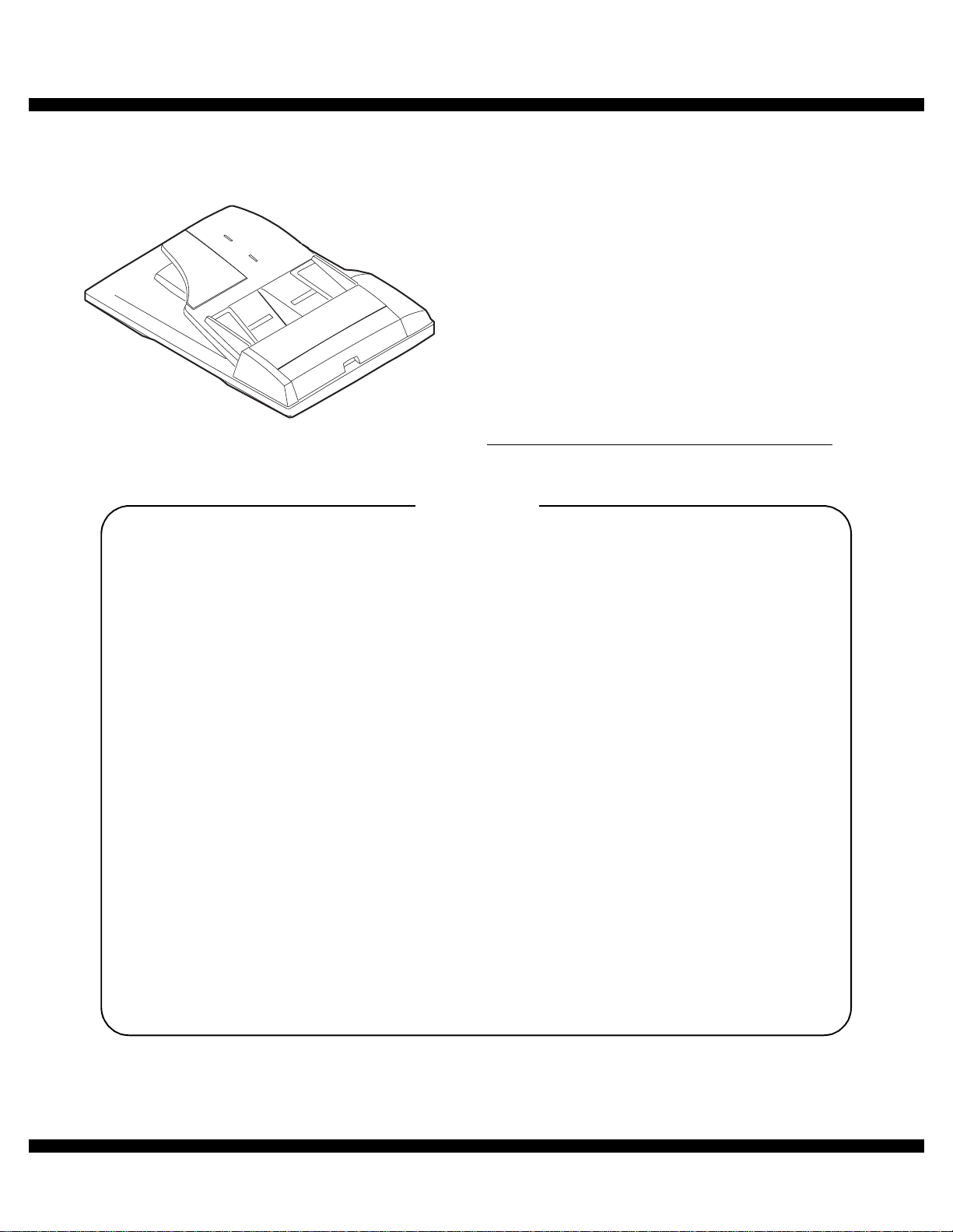
[1] PRODUCT OUTLIN E
Duplex document auto feeder AR-RP6N and document auto feeder
AR-SP6N attached to a digital copier feeds originals autom atically to
allow continuous copying.
[2] SPECIFICATIONS
AR-RP6N AR-SP6N
Document set direction Face up
Document set position Right/Center reference
Document transport
system
Document feed sequence
Document size AB series: A3 ~ A5
Document weight 56 ~ 90g/m
Document set quantity Max. 40 sheets (Stack range: within 4mm)
Dimensions 583mm (W) x 435mm (D) x 133mm (H)
Weight About 5.4 kg About 5.0 kg
Power source Supplied from the copier. (DC 24V, 5V)
Power consumption 26.4W 21W
Document size detection On the document feed tray
Detection size Japan: A3, B4, A4, A4R, B5, B5R, A5
Mixture of different
document sizes
Document reverse Allowed
Display section (LED) None
Document exchange
speed
Sheet through type
Top take-up feed
Inch series: 11 x 17 ~ 8.5 x 5.5
2
, 15 ~ 24lbs
2
: Set capacity = 30 sheets)
(90g/m
Inch series: 11 x 17, 8.5 x 14, 8.5 x 11,
EX AB series:A3, B4, A4, A4R, A5, B5, B5 R
Mixture paper feed: Not available
Random paper feed: Not available
(without 8.5 x 5.5)
S
S, 16 sheets/min (AR-M165/M162)
3
S
S, 20 sheets/min (AR-M207)
3
8.5 x 11R, 8.5 x 5.5
Not allowed
[3] UNPACKING AND INSTALLATION
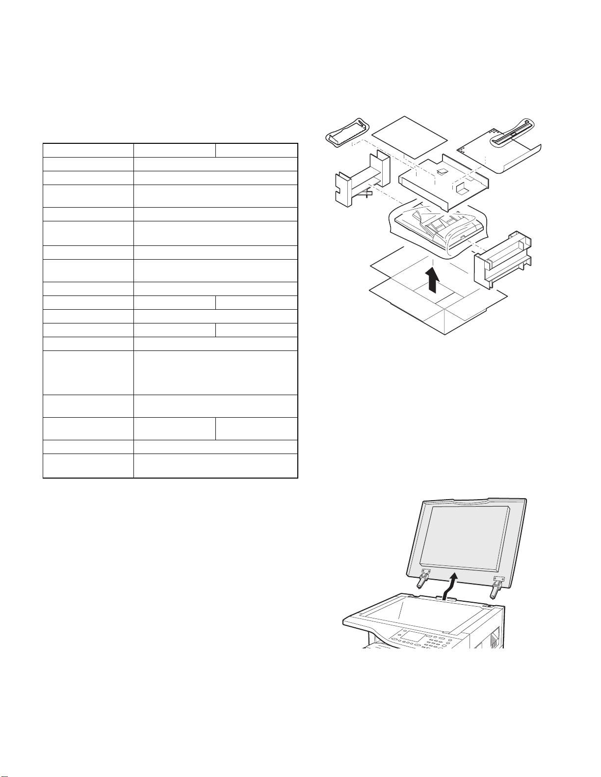
1. Unpacking
For unpacking, refer to the figure below.
2. Installation
Turn the main switch of the copier to the “OFF” position and then
remove the power plug of the copier from the outlet.
1. Remove the document cover.
Lift the document cover from the copier and tilt it to the rear side to
remove it.
AR-SP6N/RP6N PRODUCT OUTLINE
– 1 –
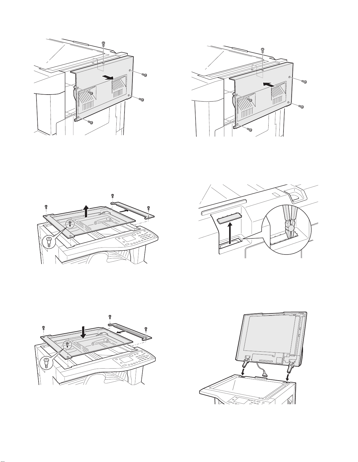
2. Remove the right cabinet.
Remove the screws and open the side door, and remove the rig ht cabi net.
5. Attach the right cabinet.
Reattach the right cabinet to its original position and fix it with the
screws.
3. Remove the document glass and the right document
glass holder.
Remove the screws, remove the document glass from the copier, and
then remove the right document glass holder.
4. Attach t he SPF glass holder.
Fit the SPF glass holder to the document glass.
Attach the document glass to the copier and fix it with the screws.
6. Cut out the cut-out portion.
Cut out the cut-out portion of the rear cabinet with nippers or the like.
At this time, be careful about the orientation of the nippers so that the
cut plane of the rear cabinet is flat.
7. Attach the automatic document feeder.
Insert the hinge portions of the document feeder into the mounting portions of the copier by holding the feeder at an angle toward the rear
side.
AR-SP6N/RP6N UNPACKING AND INSTALLATION
– 2 –
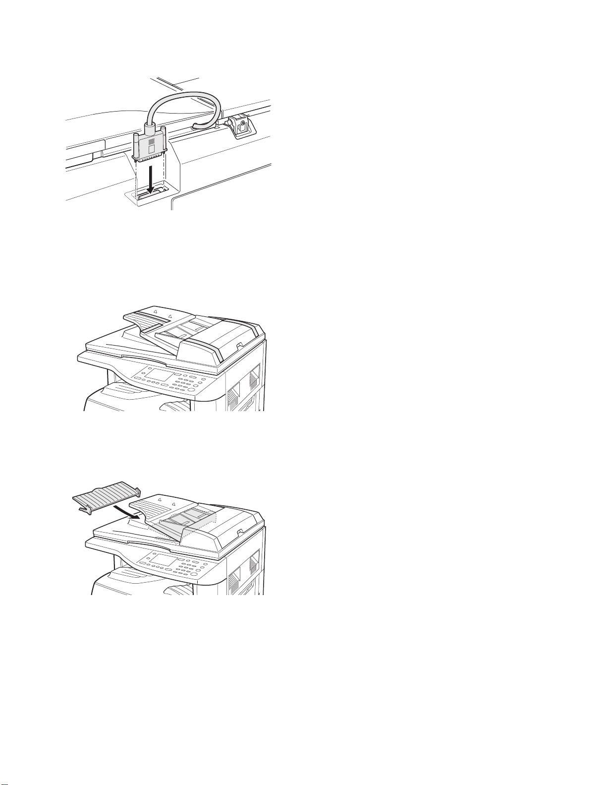
8. Connect the relay connector.
Connect the harness of the automatic document feeder to the connector of the copier and tighten the screws on the connector.
9. Remove the filament tape.
Remove the filament tape located in the positions shown in the illustration.
Insert the power plug of the copier to the outlet and turn on the main switch of the copier.
11. Check the SPF scanning position switching setting.
• Execute simulation 53-10 (SPF scanning position sw itching setting)
and check that the setting value is [1]. (If the value is [0], change it to
[1].)
12. Adjust the white compensation pixels.
• Open the automatic document feeder, execute simulation 63-7 referring to the service manual, and adjust the automatic white compensation pixels of the document feeder.
13. Check the copy magnification ratio.
• Set an original on the document glass and copy it.
Then, set an original in the document feeder tray and copy it.
• If the magnification rat io of the copy f rom the document feeder is different from that of the copy from the document glass, execute simulation 48-5 to carry out adjustment referring to the service manual.
14. Check the center displacement.
• Set an original on the document glass and copy it.
Then, set an original in the document feeder tray and copy it.
• If the center of the copy imag e from the document feeder is different
from that of the copy image from the document glass, execute simulation 50-12 to carry out adjustment referring to the service manual.
15. Check the top end position.
• Set an original on the document glass and copy it.
Then, set an original in the document feeder tray and copy it.
• If the top end position of the copy image from the document feeder is
different from that of the copy image from the document glass, execute simulation 50-06 to carry out adjustment referring to the service
manual.
10. Attach the intermediate tray. (AR-RP6N only)
Insert the intermediate tray all the way into the document feeder.
AR-SP6N/RP6N UNPACKING AND INSTALLATION
– 3 –

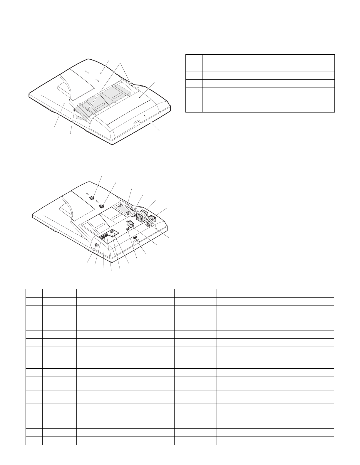
[4] EXTERNAL VIEW AND INTERNAL STRUCTURE
1. External view
5
6
2. Internal structure
14
1
2
3
No. Name
1 Document set tray
2 Document guide
3 Document feed section cover
4 Document transport section cover
5 Document exit section
6 Middle tray (AR-RP6N only)
4
13
12
11
10
8
9
6
7
15
5
4
3
16
2
1
Sensor, detector, etc.
No. Code Name Type Function/Operation Note
1 W0 Document set sensor Photo transmission Detects presence of documents.
2 COVER Open/close sensor Photo transmission Detects open/close of the paper feed unit.
3 W1 Document width sensor (A4R, LTR, A5, IV) Photo transmission Detects the document width on the tray.
4 W2 Document width sensor (B4, B5) Photo transmission Detects the document width on the tray.
5 W3 Document width sensor (WLTR, A3, A4, LT) Photo transmis sion Detects the document width on the tray.
6 PSOL Pickup solenoid — —
7 PAPER Paper entry sensor Photo transmission Detects presence of documents.
8 RSOL Pressure releas e solenoid — — AR-RP6N
9 CLH Transport clutch — —
10 MOT SPF (RSPF) motor Stepping motor Drives document feed on the tray, trans-
port, and paper exit roller.
11 GSOL Gate solenoid — — AR-RP6N
12 — Interface PWB — —
13 L1 Document length detection SW (Short) Photo transmission Detects the document length on the tray.
14 L2 Document length detection SW (Long) Photo transmission Detects the document length on the tray.
15 COVER OPEN Book sensor Photo transmission Detects the SPF (RSPF) float.
16 PO Paper exit sensor Photo transmission Detects presence of documents.
AR-SP6N/RP6N EXTERNAL VIEW AND INTERNAL STRUCTURE
– 4 –
only
only

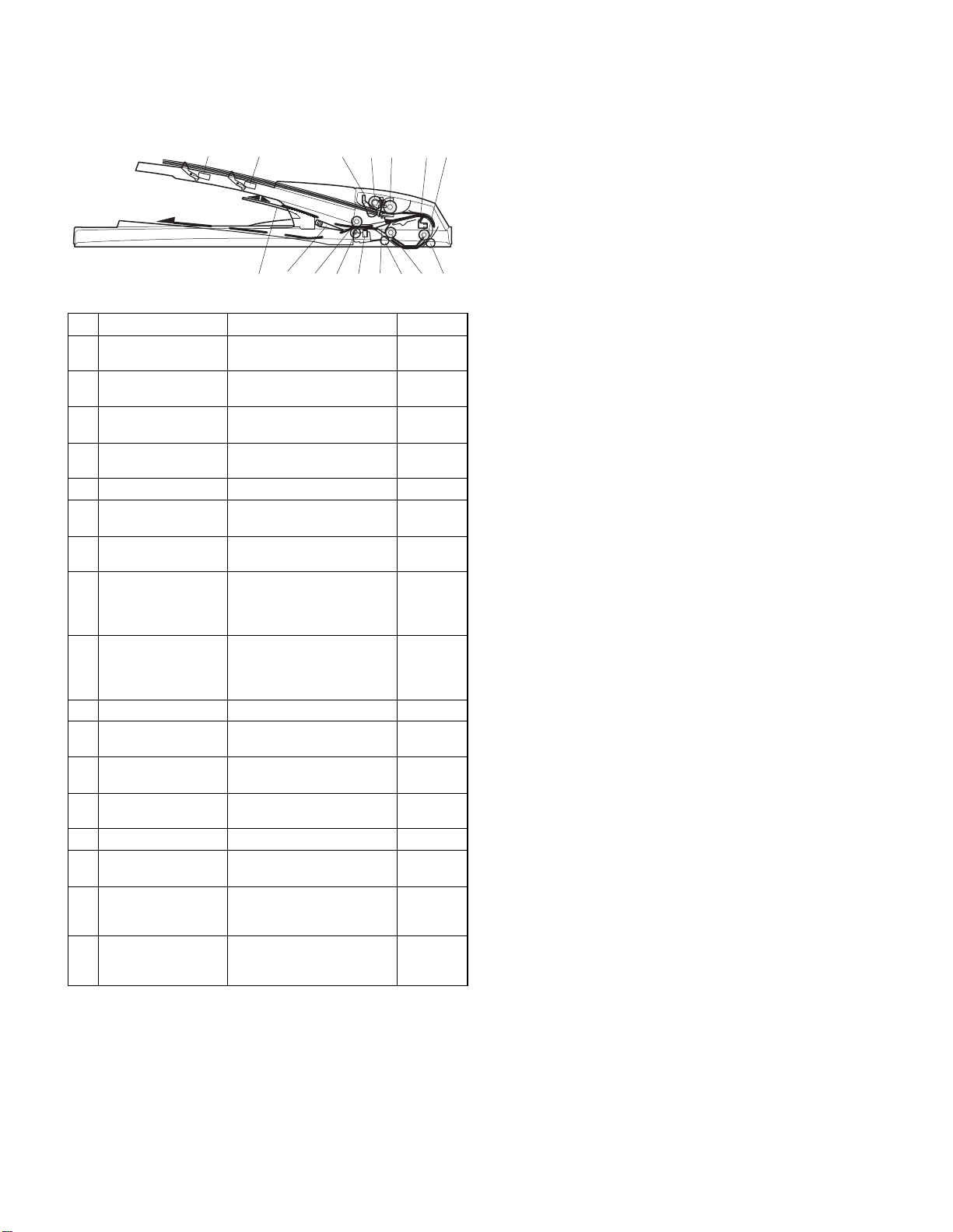
[5] OPEREATIONAL DESCRIPTIONS
1. Major parts of the paper feed section 2. Out line of operations
1 2 3,4 5 6 7 8
12
No. Part name Operation Note
1 Document length
sensor (L2)
2 Document length
sensor (L1)
3 Document set
sensor (W0)
4 Document width
sensor (W1, W2, W3)
5 Pickup roller Picks up documents.
6 Paper feed roller Feeds and transports docu-
7 Paper entry sensor
(PAPER)
8 PS roller Makes synchronization
9 PS follower roller Makes synchronization
10 Transport roller T ranspor ts documents.
11 Transport follower
roller
12 Paper exit sensor
(PO)
13 Paper exit follower
roller
14 Paper exit roller Discharges documents.
15 Reverse gate Opens/closes the document
16 Paper exit gate Separate document exit to
17 Intermediate tray Discharges documents to the
Detects the document length
on the tray.
Detects the document length
on the tray.
Detects presence of documents.
Detects the document width.
ments.
Detects transport of docu-
ments.
between the document lead
edge and the image lead
edge.
between the document lead
edge and the image lead
edge.
Transports documents.
Detects transport of documents.
Discharges documents.
reverse path.
the intermediate or the paper
exit tray.
intermediate tray during document reverse.
AR-RP6N
only
AR-RP6N
only
910111314 151617
Q AR-RP6N (RSPF)
[Duplex documents]
1) Document set (Document set sensor ON)
2) Document size detection (Document width sensors W1, W2, W3
3) Copier COPY key ON
4) RSPF motor ON
5) Pickup solenoid ON
6) Pickup roller and paper feed roller rotation
7) Paper entry sensor detects the document presence.
8) PS roller rotation
9) Copying (Front surface of document)
10) Transport roller rotation
11) Paper exit roller rotation
12) Paper exit gate falls down.
13) Reverse gate falls down.
14) Paper exit roller reverse rotation
15) Paper entry sensor detects document presence.
16) PS roller rotation
17) Copying (Back surface of document)
18) Transport roller rotation
19) Paper exit roller rotation
20) Paper exit gate falls down
21) Reverse gate falls down.
22) Paper exit roller reverse rotation
23) Paper entry sensor detects document presence.
24) PS roller rotation
25) Paper exit roller rotation
26) Paper exit gate lifts up.
27) Documents are fed to the paper exit tray.
28) Next document 3 (YES) 3 Go to 4).
29) RSPF motor OFF
4
detect the document width, and document length sensors L1, L2 detect the
4
4
4
4
4
4
4
4
4
4
(Documents are discharged to the intermediate tray.)
4
4
(Documents are fed to the reverse path.)
4
4
4
4
4
4
(Documents are discharged to the intermediate tray.)
4
4
(Documents are fed to the reverse path.)
4
4
4
4
4
4
(NO)
4
document length.)
AR-SP6N/RP6N OPEREATIONAL DESCRIPTIONS
– 5 –
Q AR-SP6N (SPF)
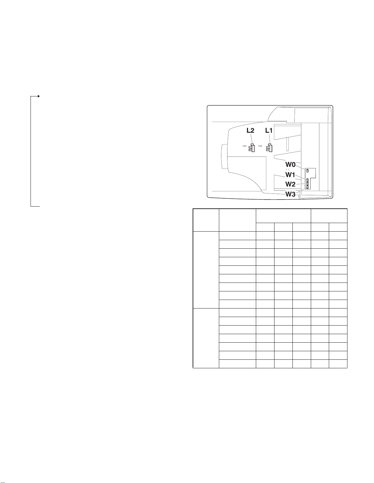
3. Document size detection
1) Document set (Document set sensor ON)
4
2) Document size detection (Document width sensors W1,
W2, W3 detect the document
width, and document length sensors L1, L2 detect the document
length.)
4
3) Copier COPY key ON
4
4) SPF motor ON
4
5) Pickup solenoid ON
4
6) Pickup roller and paper feed roller rotation
4
7) Paper entry sensor detects the document presence.
4
8) PS roller rotation
4
9) Copying (Front surface of document)
4
10) Transport roller rotation
4
11) Paper exit roller rotation
4
12) Documents are fed to the paper exit tray.
4
13) Next document 3 (YES) 3 Go to 4).
(NO)
14) SPF motor OFF
4
1) Document size detection with the document set tray
When documents are set on the document set tray in the auto selection
mode of paper/copy magnification ratio, the document size is detect ed
and paper and the copy magnification ratio are automatically selected.
When different sizes of documents are set, the max. size is detected.
The document width is detected by the document width sensors (W1,
W2, W3), and the document length is detected by the d ocument length
sensors (L1, L2) to identify the document size. Judgment of the document size is made in a certain timing af ter detecting the doc ument w ith
the document set sensor (W0).
Document
length sensor
AB series
Inch
series
Document set
size and set
direction
A5
B5
A5R
A4
B5R
A4R
8.5” x 13”
B4
A3
8.5” x 5.5”
8.5” x 5.5”R
11” x 8.5”
11” x 8.5”R
8.5” x 13”
8.5” x 14”
11” x 17”
Document width sensor
W1 W2 W3 L1 L2
onnnn
oonnn
nnnnn
ooonn
nnnon
onnon
onnoo
oonoo
ooooo
onnnn
nnnnn
ooonn
onnon
onnoo
onnoo
ooooo
Note: Detection sensor ON:
AR-SP6N/RP6N OPEREATIONAL DESCRIPTIONS
– 6 –
, OFF:
o
n
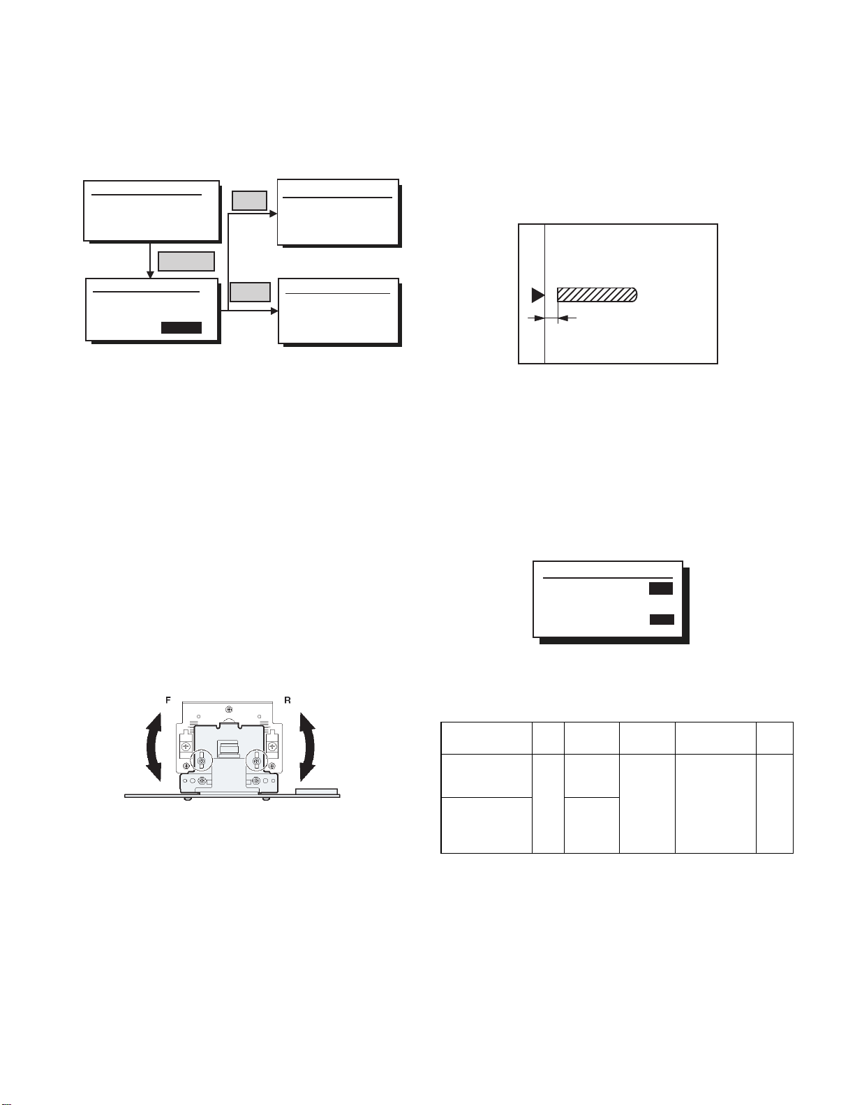
[6] ADJUSTMENTS
(1) Auto white correction pixel adjustment
1) Open the SPF fully.
2) Execute SIM63-7.
(
Initial window)
Sim63-7 SPF ADJ.
WHITE ADJUST
PRESS OK KEY EXEC
(Execution window)
Sim63-7 SPF ADJ
WHITE ADJUST
OK/START
EXEC
Failure
Success
3) When the process is completed, "COMPLETE" is displayed on the
LCD.
4) When "EROR" is displayed, perform the following procedures.
Q When the display is "- - -"
• Is the SPF closed?
• Is the lamp lighted? (If the lamp is not lighted, check the connector.)
• Is the CCD harness properly connected to the MCU connector?
Q When the display is 281 or above:
1) Remove the table glass.
2) Remove the dark box.
3) Sli de the lens uni t to the front side and insta ll it. Execute the simulation .
Q When the display is 143 or below:
1) Remove the table glass.
2) Remove the dark box.
3) Sli de t he lens un it t o the rea r side and inst all i t. Execut e the simulat ion.
Sim63-7 SPF ADJ.
WHITE ADJUST
ERROR
[---]
PRESS OK KEY EXEC
Sim63-7 SPF ADJ
WHITE ADJUST
COMPLETE
[160]
PRESS OK KEY EXEC
(2) Magnification ratio adjustment
Note: • When performing this adjustment, check that the CCD unit is
1) Place a scale on the OC table as shown below, and make a
2) Set the test chart to the SPF (RSPF) and make a normal copy.
3) Compare the copy and the test chart.
4) Execute SIM 48-5.
5) After completion of warming up, shading is performed.
6) Check to confirm that "RSPF(SIDE1)" mode is selected with the
7) Enter the set value, and press the START key.
<Adjustment specifications>
properly installed.
• When performing this adjustment, check that the OC mode
adjustment in copying is completed.
normal copy to make a test chart.
Note: Since the printed paper is used as the test chart,
place the scale in parallel to both sides.
If an adjustment is needed, perform the following procedures.
cross cursor.
Sim48-5 (R)SPF ZOOM
1:RSPF(SIDE1)
2:RSPF(SIDE2)
[ 1- 99]
50
50
50
The entered correction value is stored and a copy is made.
When the lens unit is moved, execute the OC main scanning direction
*
magnification ratio adjustment SIM48-1 and SIM48-3, and execute
the SPF document off-center adjustment.
This adjustment is basically completed with SIM63-7.
*
AR-SP6N/RP6N ADJUSTMENTS
Adjustment
mode
Sub scanning
direction ratio
(Front)
Sub scanning
direction
magnification rat i o
(Front)
– 7 –
SIM Disp0lay
text array
48-5 RSPF
(SIDE1)
RSPF
(SIDE2)
Set value Specifications Set
range
3
Normal
1.0% 1 ~ 99
m
+1
+0.1%
-1 3
-0.1%
(3) Document off center adjustment
Note: When performing this adjustment, check that the paper off-cen-
ter is properly adjusted.
1) Set the center position adjustment test chart (made by yours elf) on
the SPF (RSPF).
<Adjustment specifications>
Draw a line in the center of paper. (In the scanning direction)
2) Make a normal copy from the manual feed tray, and compare the
copy and the test chart.
If an adjustment is required, perform the following procedures.
3) Execute SIM 50-12.
4) The current off-center adjustment value is displayed on the display
section in two digits.
5) Enter the set value and press the START key.
The entered correction value is started and a copy is made.
<Adjustment specifications>
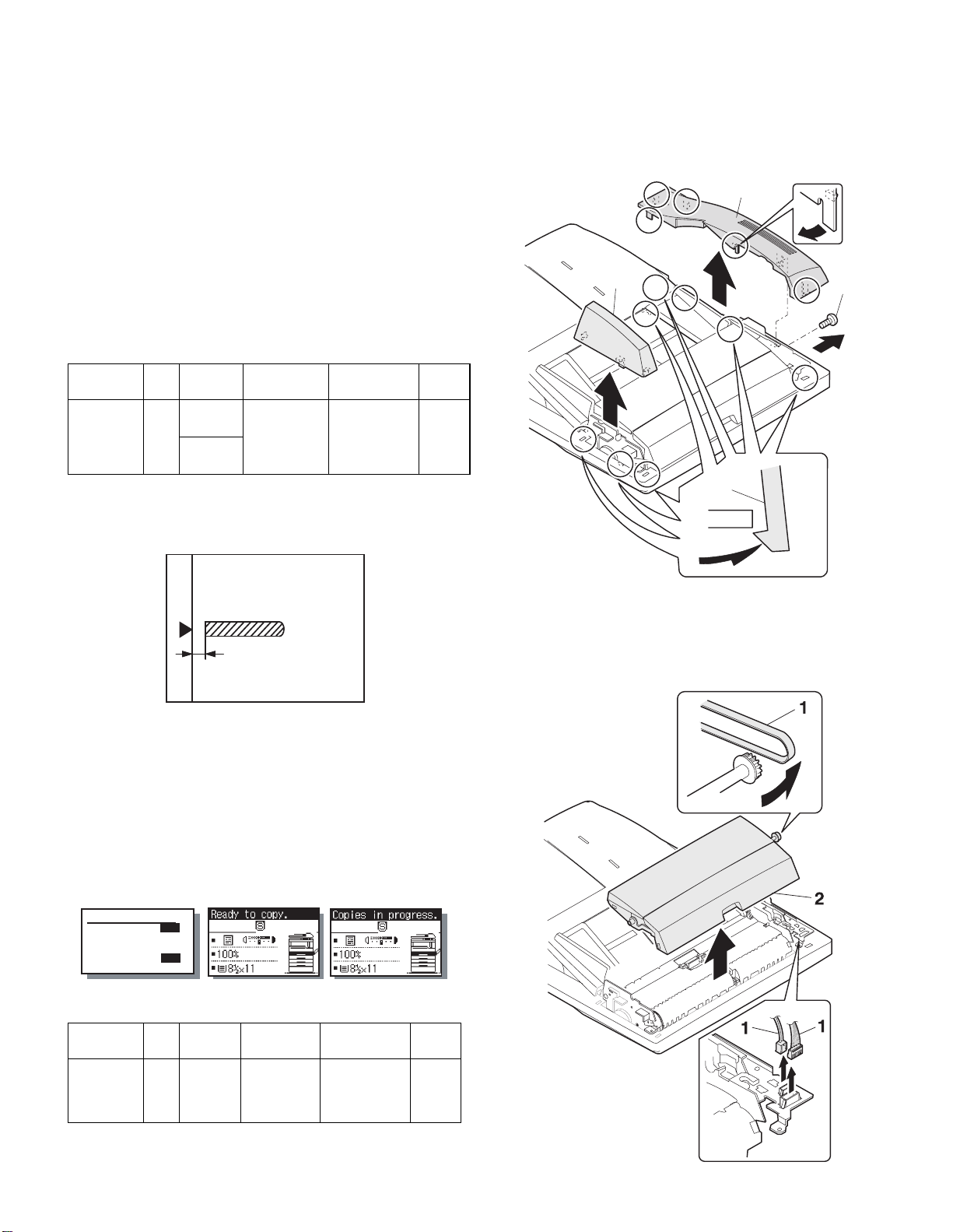
[7] DISASSEMBLY AND ASSEMBLY
1. External fitting section
Note: Turn the paw in the arrow direction.
2
3
1
Adjustment
mode
Document
off-center
SIM Disp0lay
text array
50-12 RSPF
(SIDE1)
RSPF
(SIDE2)
Set value Specifications Set
+1 3 +0.1mm
Slide to R side
-1
-0.1mm
3
Slide to L side
Center m 2.0% 1 ~ 99
range
(4) Image lead edge po sition a djustment
1) Set a scale on the OC table as shown below.
Note: Since the printed paper is used as the test chart,
place the scale in parallel to both sides.
2) Make a copy, and use the copied paper as the document and make
a copy from SPF (RSPF) again.
3) Check the copied paper. If an adjustment is re quired, perform the
following procedures.
4) Execute SIM 50-6.
5) Set the SPF/RSPF lead edge position set value so that the image
similar to the adjusted image at the OC image lead edge position
described previously is printed.
(Mode selection window)
Sim50-6 SPF EDGE
1:SIDE1
2:SIDE2
3:END EDGE
[ 1- 99]
50
50
50
50
(Copy start window) (Execution window)
2
2. Paper feed unit section
1) Paper feed unit
<Adjustment specifications>
Adjustment
mode
SPF image
lead edge
position
Refer to the AR-SP6/RP6 Service Manual about the adjustment
*
procedure required when attaching AR-SP6N to AR-M205/M160.
SIM Disp0lay
text array
50-6 SIDE1 1 step:
Set value Specifications Set
0.1mm shift
Lead edge void:
1 - 4mm
Image loss:
3mm or less
AR-SP6N/RP6 N DISASSEMBLY AND ASSEMBLY
range
1 - 99
– 8 –
 Loading...