

Page 1
q
SERVICE MANUAL
Digital copier
MODEL
CONTENTS
CODE : 00Z
ARSP6//A1E
Reverse Single
Pass Feeder (RSPF)
Single Pass Feeder (SPF)
AR-RP6
AR-SP6
[1] PRODUCT OUTLINE . . . . . . . . . . . . . . . . . . . . . . . . . . . . . . . . . . 1
[2] SPECIFICATIONS . . . . . . . . . . . . . . . . . . . . . . . . . . . . . . . . . . . . 1
[3] UNPACKING AND INSTALLATION . . . . . . . . . . . . . . . . . . . . . . . 1
[4] EXTERNAL VIEW AND INTERNAL STRUCTURE . . . . . . . . . . . 4
[5] OPEREATIONAL DESCRIPTIONS . . . . . . . . . . . . . . . . . . . . . . . 5
[6] ADJUSTMENTS . . . . . . . . . . . . . . . . . . . . . . . . . . . . . . . . . . . . . . 7
[7] DISASSEMBLY AND ASSEMBLY . . . . . . . . . . . . . . . . . . . . . . . . 8
[8] MAINTENANCE . . . . . . . . . . . . . . . . . . . . . . . . . . . . . . . . . . . . . 14
[9] ELECTRICAL SECTION. . . . . . . . . . . . . . . . . . . . . . . . . . . . . . . 15
Parts marked with "!" are important for maintaining the safety of the set. Be sure to replace these parts with specified
ones for maintaining the safety and performance of the set.
This document has been published to be used
SHARP CORPORATION
for after sales servic e only.
The contents are subject to change without notice.
Page 2

Page 3
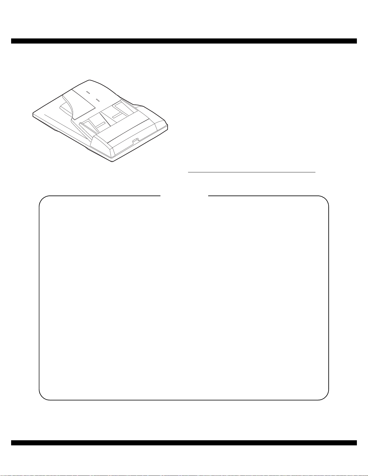
[1] PRODUCT OUTLINE
This machine is a duplex document auto feeder attached to a digital
copier.
It feeds originals automatically to allow continuous copying.
[2] SPECIFICATIONS
AR-RP6 AR-SP6
Document set direction Face up
Document set position Right/Center reference
Document transport
system
Document feed sequence Top take-up feed
Document size AB series: A3 ~ A5
Document weight 56 ~ 90g/m
Document set quantity Max. 40 sheets (Stack range: within 4mm)
Dimensions 583mm (W) x 435mm (D) x 133mm (H)
Weight About 5.4 kg About 5.0 kg
Power source S up p l i ed f r o m th e
Power consumption 26.4W 21W
Document size detection On the document feed tray
Detection size Japan: A3, B4, A4, A4R, B5, B5R,
Mixture of different
document sizes
Document reverse Allowed
Display section (LED) None
Document exchange
speed
Sheet through type
Inch series: 11 x 17 ~ 8.5 x 5.5
2
, 15 ~ 24lbs
2
: Set capacity = 30 sheets)
(90g/m
copier. (DC 24V)
Inch series: 11 x 17, 8.5 x 14, 8.5 x 11,
EX AB series: A3, B4, A4, A 4R, A 5 , B5,
Mixture paper feed: Not available
Random paper feed: Not available
(without 8.5 x 5.5)
S 3 S, 16 sheets/min (AR-160M)
S 3 S, 20 sheets/min (AR-200M)
Supplied from the
copier. (DC 24V, 5V)
A5
8.5 x 11R, 8.5 x 5.5
B5R, A5R
Not allowed
[3] UNPACKING AND INSTALLATION
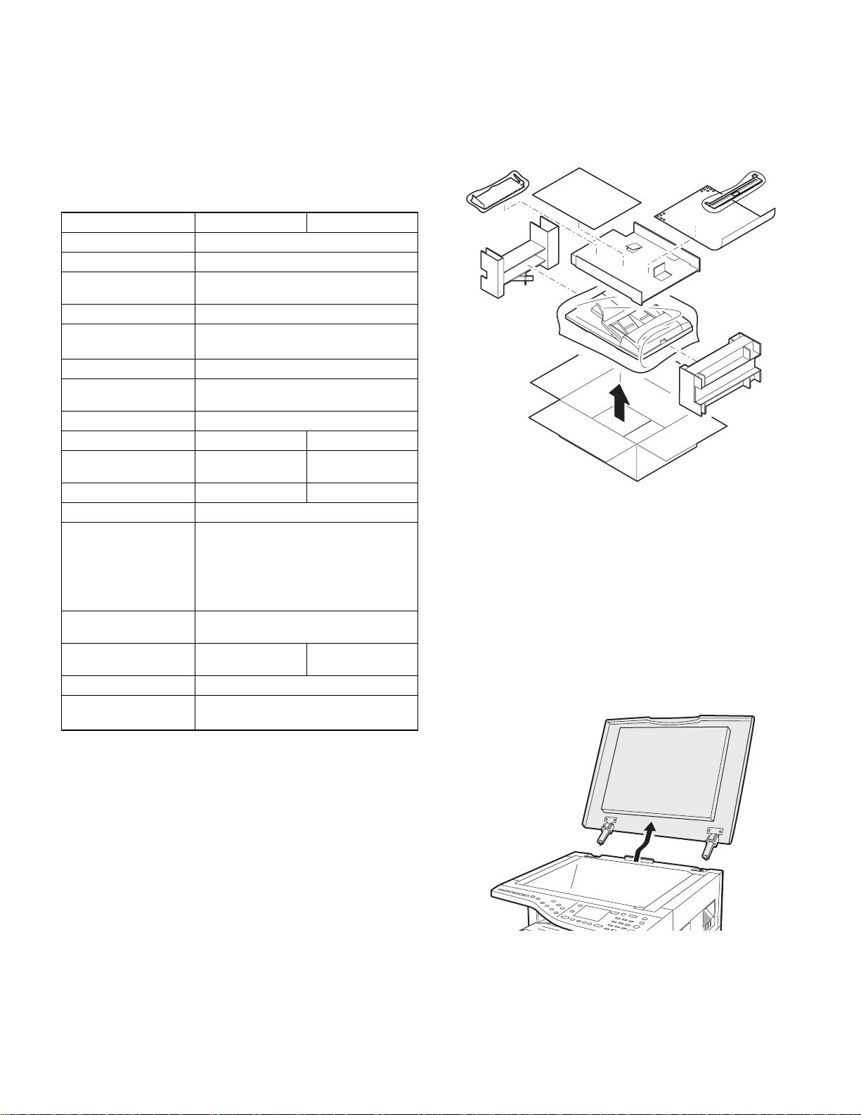
1. Unpacking
For unpacking, refer to the figure below.
2. Installation
Turn the main switch of the copier to the “OFF” position and then
remove the power plug of the copier from the outlet.
1. Remove th e document cover.
Lift the document cover from the copier and tilt it to the rear side to
remove it.
AR-SP6/RP6 PRODUCT OUTLINE
– 1 –
Page 4
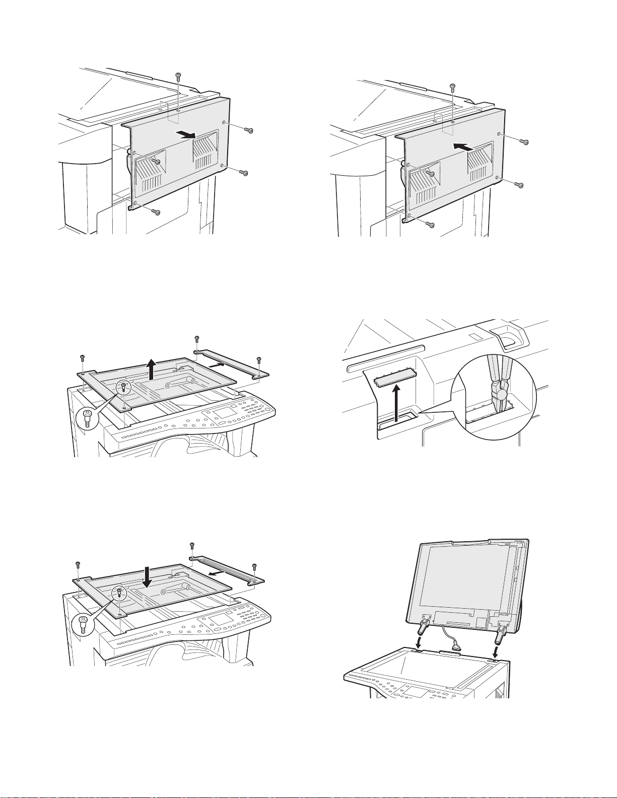
2. Remove the right cabinet.
Remove the screws and remove the right cabinet.
5. Attach the right cabinet.
Reattach the right cabinet to its original position and fix it with the
screws.
3. Remove the document glass and the right document
glass holder.
Remove the screws, remove the document glass from the copier, and
then remove the right document glass holder.
4. Attach the SPF glass holder.
Fit the SPF glass holder to the document glass.
Attach the document glass to the copier and fix it with the screws.
6. Cut out the cut-out portion.
Cut out the cut-out portion of the rear cabinet with nippers or the like.
At this time, be careful about the orientation of the nippers so that the
cut plane of the rear cabinet is flat.
7. Attach the automatic document feeder.
Insert the hinge portions of the document feeder into the mounting portions of the copier by holding the feeder at an angle toward the rear
side.
AR-SP6/RP6 UNPACKING AND INSTALLATION
– 2 –
Page 5
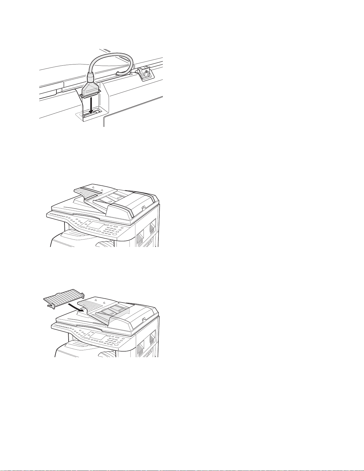
8. Connect the relay connector.
Connect the harness of the automatic document feeder to the connector of the copier and tighten the screws on the connector.
9. Remove the filament tape.
Remove the filament tape located in the positions shown in the illustration.
Insert the power plug of the copier to the outl et and turn on
the main switch of the copier.
11. Adjust the white compensation pixels.
• Open the automatic document feeder, execute simulation 63-7 referring to the service manual, and adjust the automatic white compensation pixels of the document feeder.
12. Check the copy magnification ratio.
• Set an original on the document glass and copy it.
Then, set an original in the document feeder tray and copy it.
• If the magnification ratio of the copy from the document feeder is different from that of the copy from the document glass, execute simulation 48-5 to carry out adjustment referring to the service manual.
13. Check the center displacement.
• Set an original on the document glass and copy it.
Then, set an original in the document feeder tray and copy it.
• If the center of the copy image from the document feeder is different
from that of the copy image from the document glass, execute simulation 50-12 to carry out adjustment referring to the service manual.
14. Check the top end position.
• Set an original on the document glass and copy it.
Then, set an original in the document feeder tray and copy it.
• If the top end position of the copy image from the document feeder is
different from that of the copy image from the document glass, execute simulation 50-06 to carry out adjustment referring to the service
manual.
10. Attach the intermediate tray. (AR-RP6 only)
Insert the intermediate tray all the way into the document feeder.
AR-SP6/RP6 UNPACKING AND INSTALLATION
– 3 –
Page 6
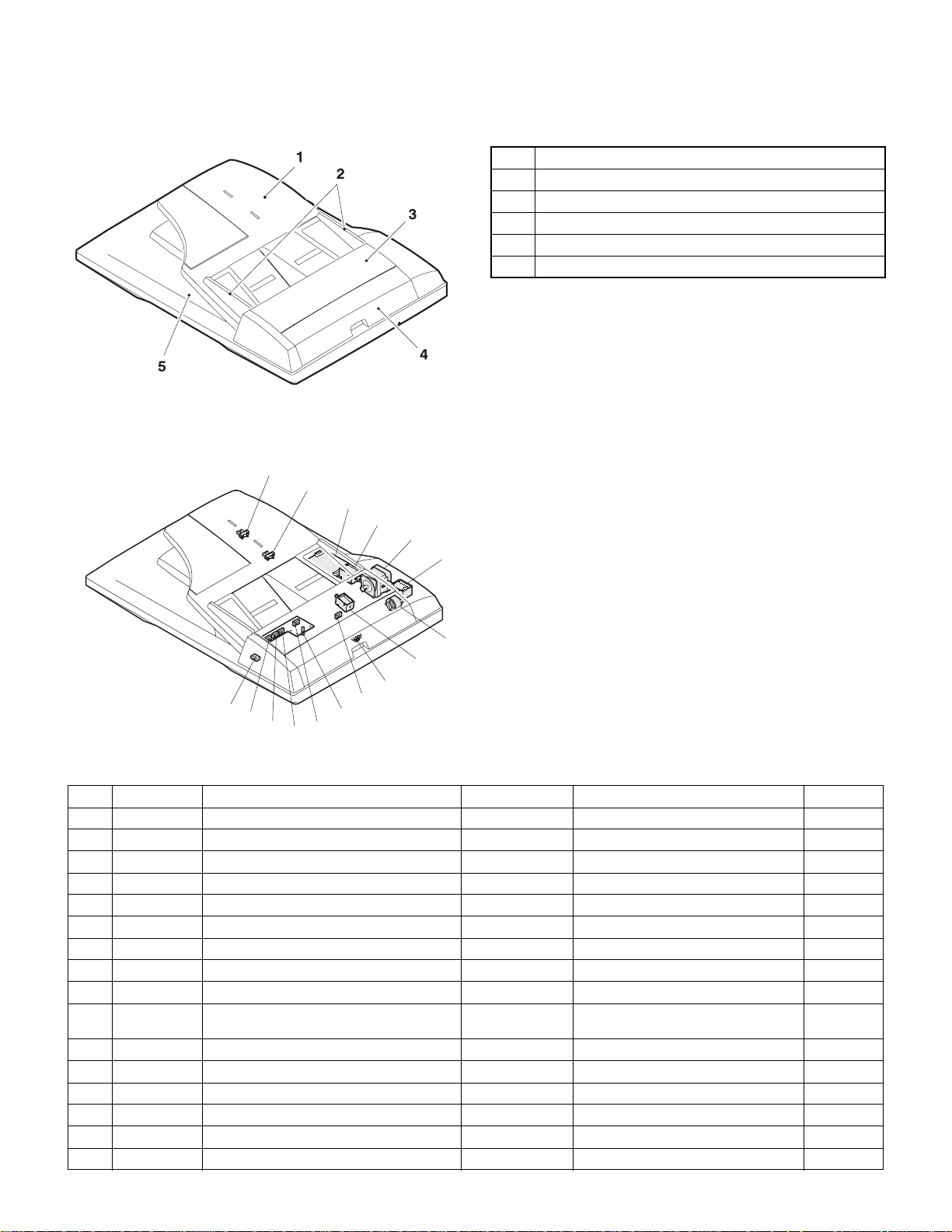
[4] EXTERNAL VIEW AND INTERNAL STRUCTURE
1. External view
No. Name
1 Document set tray
2 Document guide
3 Document feed section cover
4 Document transport section cover
5 Document exit section
2. Internal structure
14
13
12
11
10
8
9
6
7
15
5
4
3
16
2
1
Sensor, detector, etc.
No. Code Name Type Function/Operation Note
1 W0 Document set sensor Photo transmission Detects presence of documents.
2 COVER Open/close sensor Photo transmission Detects open/close of the paper feed unit.
3 W1 Document width sensor (A4R, LTR, A5) Photo transmission Detects the document width on the tray.
4 W2 Document width sensor (B4, B5) Photo transmission Detects the document width on the tray.
5 W3 Document width sensor (WL, TR, A5R, A4, LT) Photo transmission Detects the document width on the tray.
6 PSOL Pickup solenoid — —
7 PAPER Paper entry sensor Photo transmission Detects presence of documents.
8 RSOL Pressure release solenoid — — AR-RP6 only
9 CLH Transport clutch — —
10 MOT SPF (RSPF) motor Stepping motor Drives document feed on the tray, trans-
11 GSOL Gate solenoid — — AR-RP6 only
12 — Interface PWB — —
13 L1 Document length detection SW (Short) Photo transmission Detects the document length on the tray.
14 L2 Document length detection SW (Long) Photo transmission Detects the document length on the tray.
15 COVER OPEN Book sensor Photo transmission Detects the SPF (RSPF) float.
16 PO Paper exit sensor Photo transmission Detects presence of documents.
port, and paper exit roller.
AR-SP6/RP6 EXTERNAL VIEW AND INTERNAL STRUCTURE
– 4 –
Page 7
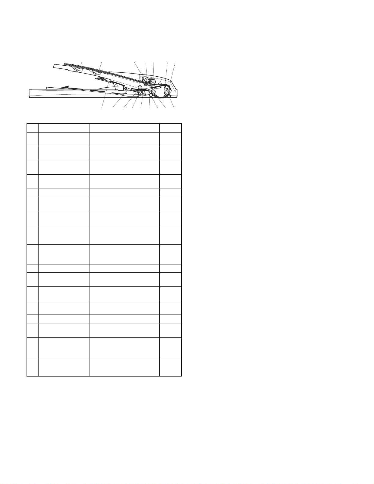
[5] OPEREATIONAL DESCRIPTIONS
1. Major parts of the paper feed section 2. Out line of operations
1 2 3,4 5 6 7 8
12
No. Part name Operation Note
1 Document length
sensor (L2)
2 Document length
sensor (L1)
3 Document set
sensor (W0)
4 Document width
sensor (W1, W2, W3)
5 Pickup roller Picks up documents.
6 Paper feed roller Feeds and transports docu-
7 Paper entry sensor
(PAPER)
8 PS roller Makes synchronization
9 PS follower roller Makes synchronization
10 Transport roller Transports documents.
11 Transport follower
roller
12 Paper exit sensor
(PO)
13 Paper exit follower
roller
14 Paper exit roller Discharges documents.
15 Reverse gate Opens/closes the document
16 Paper exit gate Separate document exit to the
17 Intermediate tray Discharges documents to the
Detects the document length
on the tray.
Detects the document length
on the tray.
Detects presence of documents.
Detects the document width.
ments.
Detects transport of docu-
ments.
between the document lead
edge and the image lead edge.
between the document lead
edge and the image lead edge.
Transports documents.
Detects transport of documents.
Discharges documents.
reverse path.
intermediate or the paper exit
tray.
intermediate tray during document reverse.
AR-RP6
only
AR-RP6
only
910111314 151617
■AR-RP6 (RSPF)
[Duplex documents]
1) Document set (Document set sensor ON)
4
2) Document size detection (Document width sensors W1, W2, W3
detect the document width, and document length sensors L1, L2 detect the
document length.)
4
3) Copier COPY key ON
4
4) RSPF motor ON
4
5) Pickup solenoid ON
4
6) Pickup roller and paper feed roller rotation
4
7) Paper entry sensor detects the document presence.
4
8) PS roller rotation
4
9) Copying (Front surface of document)
4
10) Transport roller rotation
4
11) Paper exit roller rotation
4
12) Paper exit gate falls down.
(Documents are discharged to the intermediate tray.)
4
13) Reverse gate falls down.
4
14) Paper exit roller reverse rotation
(Documents are fed to the reverse path.)
4
15) Paper entry sensor detects document presence.
4
16) PS roller rotation
4
17) Copying (Back surface of document)
4
18) Transport roller rotation
4
19) Paper exit roller rotation
4
20) Paper exit gate falls down
(Documents are discharged to the intermediate tray.)
4
21) Reverse gate falls down.
4
22) Paper exit roller reverse rotation
(Documents are fed to the reverse path.)
4
23) Paper entry sensor detects document presence.
4
24) PS roller rotation
4
25) Paper exit roller rotation
4
26) Paper exit gate lifts up.
4
27) Documents are fed to the paper exit tray.
4
28) Next document 3 (YES) 3 Go to 4).
4 (NO)
29) RSPF motor OFF
AR-SP6/RP6 OPEREATIONAL DESCRIPTIONS
– 5 –
Page 8
■AR-SP6 (SPF)
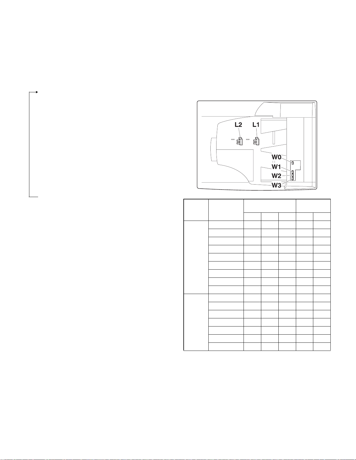
3. Document size detection
1) Document set (Document set sensor ON)
4
2) Document size detection (Document width sensors W1,
W2, W3 detect the document
width, and document length sensors L1, L2 detect the document
length.)
4
3) Copier COPY key ON
4
4) SPF motor ON
4
5) Pickup solenoid ON
4
6) Pickup roller and paper feed roller rotation
4
7) Paper entry sensor detects the document presence.
4
8) PS roller rotation
4
9) Copying (Front surface of document)
4
10) Transport roller rotation
4
11) Paper exit roller rotation
4
12) Documents are fed to the paper exit tray.
4
13) Next document 3 (YES) 3 Go to 4).
4 (NO)
14) SPF motor OFF
1) Document size detection with the document set tray
When documents are set on the document set tray in the auto selection
mode of paper/copy magnification ratio, the document size is detected
and paper and the copy magnification ratio are automatically selected.
When different sizes of documents are set, the max. size is detected.
The document width is detected by the document width sensors (W1,
W2, W3), and the document length is detected by the document length
sensors (L1, L2) to identify the document size. Judgement of the document size is made in a certain timing after detecting the document w ith
the document set sensor (W0).
Document
length sensor
AB series
Inch
series
Document set
size and set
direction
A5 onnnn
B5 oonnn
A5R nnnnn
A4 ooonn
B5R nnnon
A4R onnon
8.5” x 13” onnoo
B4 onnoo
A3 ooooo
8.5” x 5.5” onnnn
8.5” x 5.5”R nnnnn
11” x 8.5” ooonn
11” x 8.5”R onnon
8.5” x 13” onnoo
8.5” x 14” onnoo
11” x 17” ooooo
Document width sensor
W1 W2 W3 L1 L2
Note: Detection sensor ON: o, OFF: n
AR-SP6/RP6 OPEREATIONAL DESCRIPTIONS
– 6 –
Page 9
[6] ADJUSTMENTS
(1) Auto white correction pixel adjustment
[Function]
The white correction start pixel position is automatically adjusted.
This adjustment is performed after the lens unit is replaced.
[Operation]
Open the SPF (RSPF) unit and press the [OK] key.
7-segment indicates the order number of the pixel of the white sheet for SPF (RSPF)
exposure correction in the SPF (RSPF) position.
It will display on 7-segment, if values are 93-299, and data are written into the EEPROM.
It will display on 7-segment, it values are 0-92 or 230-999, and data are not written into
the EEPROM.
It will display "--" on 7-segment, it values is 1000 or larger, and data are not written into
the EEPROM..
[CA] key: Cancels the test command.
[Interruption] key: Shifts to the sub code entry menu.
The SPF white correction start pixel = Displayed pixel position - 34
Interruption is inhibited during execution.
If the simulation is executed with the SPF unit closed, an error is resulted.
During execution,"EXEC" is highlighted
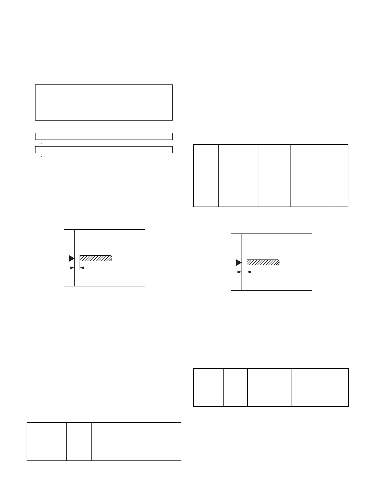
(2) Magnification ratio adjustment
Note: • When performing this adjustment, check that the CCD unit is
properly installed.
• When performing this adjustment, check that the OC mode
adjustment in copying is completed.
1) Place a scale on the document table as shown be low, and make a
normal copy to make a test chart.
(3) Document off center adjustment
Note: When performing this adjustment, check that the paper off-cen-
ter is properly adjusted.
1) Set the center position adjustment test chart (made by yourself) on
the SPF (RSPF).
<Adjustment specifications>
Draw a line in the center of paper. (In the scanning direction)
2) Make a normal copy from the manual feed tray, and co mpare the
copy and the test chart.
If an adjustment is required, perform the following procedures.
3) Execute SIM 50-12.
4) The current off-center adjustment value is displayed on the display
section in two digits.
5) Enter the set value and press the START key.
The entered correction value is started and a copy is made.
<Adjustment specifications>
Mode Specification SIM Set value
Document
off-center
(AR-RP6)
Document
off-center
(AR-SP6)
Simplex:
Center
Duplex:
Center
m
m
3.0mm
3.5mm
SIM 50-12
TEXT:
SPF surface
PHOTO:
SPF back
AE: Surface
TEXT: Back
Add 1:
0.1mm shifted to
R side.
Reduce 1:
0.1mm shifted to
L side.
Set
range
1 ~ 99
(4) Image lead edge position adjustme nt
1) Set a scale on the OC table as shown below.
Note: Since the printed paper is used as the test chart,
place the scale in parallel to both sides.
2) Set the test chart to the SPF (RSPF) and make a normal copy.
3) Compare the copy and the test chart.
If an adjustment is needed, perform the following procedures.
4) Execute SIM 48-5.
5) The current correction value is displayed on the display section in
two digits.
6) Enter the set value, and press the START key.
The entered correction value is stored and a copy is made.
7) Change the TEXT mode.
The TEXT lamp lights up, and the current correction value of the
back surface sub scanning direction magnification ratio is displayed
on the display section in two digits.
8) Enter the set value, and press the START key.
The entered correction value is stored and a copy is made.
<Adjustment specifications>
Mode Spec SIM Set value
Magnification
ratio adjustment
Normal:
m 1.0%
SIM 48-5
AE: Surface
TEXT: Back
Add 1:
Reduce 1:
0.1% increase
0.1% decrease
Set
range
1 ~ 99
Note: Since the printed paper is used as the test chart,
place the scale in parallel to both sides.
2) Make a copy, and use the copied paper as the document and make
a copy from SPF (RSPF) again.
3) Check the copied paper. If an adjustment is required, perform the
following procedures.
4) Execute SIM 50-6.
5) Set the SPF/RSPF lead edge position set value so that the image
similar to the adjusted image at the OC image lead edge position
described previously is printed.
<Adjustment specifications>
Adjustment
mode
Image
lead edge
position
SIM Set value Specification
SIM 50-6 1step: 0.1mm shift Lead edge void:
1 ~ 4mm
Image loss:
Set
range
1 ~ 99
3mm or less
AR-SP6/RP6 ADJUSTMENTS
– 7 –
Page 10
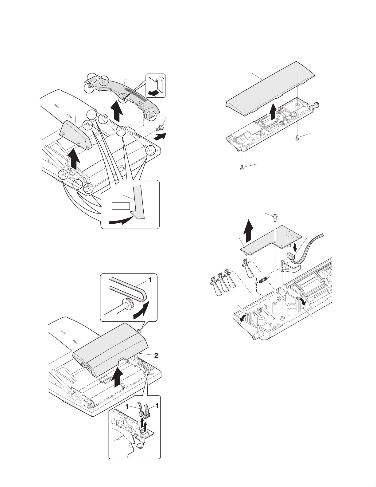
[7] DISASSEMBLY AND ASSEMBLY
1. External fitting section
Note: Turn the paw in the arrow direction.
3
2) Document feed section cover
2
2
1
1
1
2
3) Sensor PWB
1
2. Paper feed unit section
1) Paper feed unit
3
4
2
2
AR-SP6/RP6 DI SASSEMBLY AND ASSEMBLY
– 8 –
Page 11
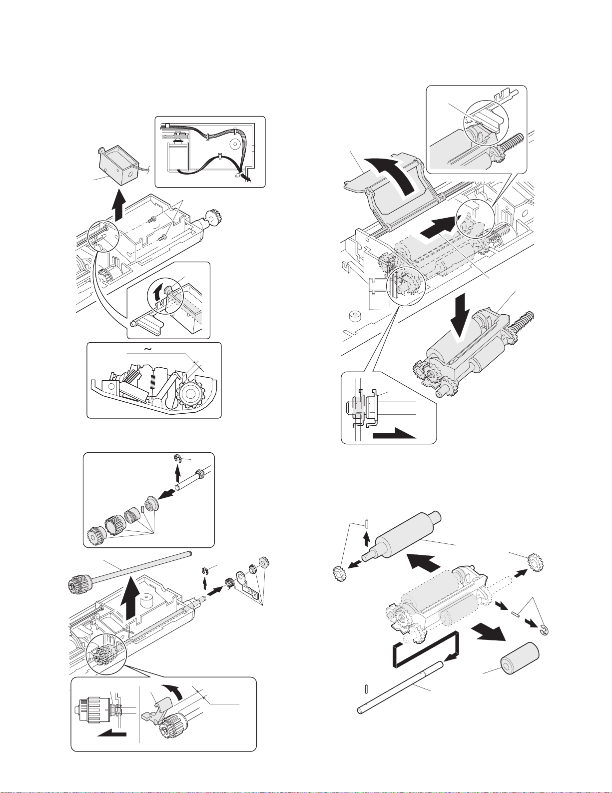
4) Pickup solenoid
Note: Remove section A of the pickup solenoid from the solenoid arm
groove.
When assembling, adjust the spacing between the clutch latch
and sleeve with the pick-up solenoid pulled. The size should be
the distance from the tip of the clutch latch and the root of the
clutch sleeve latch.
2
1
A
6) Pickup roller ass’y
Note: When assembling the pickup roller ass’y 4, check that rib A is on
the rib of the solenoid arm.
A
1
2
4
2.5 4.5mm
5) Clutch gear ass’y
5
3
6
7) Pick up roller, paper feed roller
4
6
1
2
3
1
1
3
4
From Edge pawl
2.5~4.0
1
AR-SP6/RP6 DI SASSEMBLY AND ASSEMBLY
– 9 –
2
Page 12

3. Interface PWB
5. Document tray section
1
1) Document tray
1
2
A
2
3
1
B
1
B
1
A
2) Rack cover
■■■■AR-RP6
1
1
1
4. Gate solenoid
■■■■AR-RP6 only
2
1
Bearing
■■■■AR-SP6
1
1
1
2
Note: When assembling, check that the paper exit gate hook is set in
the solenoid groove.
When assembling, the bearing D-cut surface shuold be faced
down.
AR-SP6/RP6 DI SASSEMBLY AND ASSEMBLY
– 10 –
Page 13

3) Document length sensor SW
2
1
2
1
2) Drive frame unit
1
1
1
2
1
6. Drive frame section
1) Book sensor
2
1
3) Drive frame ass’y and drive belt
3
1
2
3
4
AR-SP6/RP6 DI SASSEMBLY AND ASSEMBLY
– 11 –
Page 14

4) Pressure release solenoid
■■■■AR-RP6 only
Note: Make sure the spring pin A is inserted into the slot.
Make sure that the clearance between the position at which force
is applied and the sound deadening sponge is 0.5 ~ 2 mm when
the pressure release solenoid plunger is pulled toward the solenoid side.
0.5 2mm
7. Transport section
1) Clutch
Note: When assembling, check that the rib is in the clutch groove A
and fix it with E-ring.
2
A
A
2
5) RSPF motor / SPF motor
1
3
3
1
1
2) Transport roller gear
1
1
1
3) Reverse gate
■■■■AR-RP6 only
4
Note: When assembling the inversion gate, apply grease G-484 on the
area A.
1
1
2
A
AR-SP6/RP6 DI SASSEMBLY AND ASSEMBLY
– 12 –
3
A
A
2
1
Page 15

4) Transport roller
Note: Note that the spring will come off when removing.
■■■■AR-RP6
5) PS roller
1
1
1
■■■■AR-SP6
1
2
1
1
6) Paper feed paper guide lower
Note: When assembling, check that the paper feed paper guide lower
is securely set to rib A and boss B.
+
1mm
-
0 0.5mm
2
1
1
1
AR-SP6/RP6 DI SASSEMBLY AND ASSEMBLY
– 13 –
B
1
A
Page 16

7) Paper feed paper guide upper
[8] MAINTENANCE
1
8) Paper exit roller
2
1
1. Maintenance parts
No. Name Work item Service call Remark
1 Pickup roller Cleaning o
2-1 Separation unit Cleaning o Replace when
2-2 Front separation
sheet
3 Paper feed roller Cleaning o
4 PS roller Cleaning o
5 Transport roller Cleaning o
6 Paper exit roller Cleaning o
Cleaning o
1
worn down.
3
1
2
8. Hinge L
Note: When assembling the hinge L, reference is based on the mark of
base tray and the center line of the 5 lines of the hinge L
extended horizontally.
1
1
2
1
2-2
2-1
6
5
4
Note: When performing maintenance, refer to [7] DISASSEMBLY AND
ASSEMBLY.
AR-SP6/RP6 MAINTENANCE
– 14 –
Page 17

D
1
SENSOR
5V
C
B
SOL/CLU
A
RSPF ONLY
5V
5V
24V
24V
5V
24V
24V
24V
24V
24V
234
L2
L1
W0W1W2
SPF SENSOR PWB
W3
PAPER
/SPFOUT
SPFOPEN
/CLH
/PSOL
/RSOL
/GSOL
MOTOR
(A,B,/A,/B)
2 1
/SPFCOVER
3
5
DATA
SELECTOR
5V
TRANSISTOR
24V
ARRAY
MOTOR
DRIVER
5 4
SPF/RSPF INTERFACE PWB
678
7 6
[9] ELECTRICAL SECTION
1. Block diagram
PEGASUS
(MCU PWB)
D
YSPF
/SPFCOVER
SEL(A#,B#,C#)
C
AR-SP6/RP6 ELECTRICAL SECTION
PAPER
– 15 –
/SPFOUT
SPFOPEN
SPF(CLH,PSOL,RSOL,GSOL)
B
/MODA,/MODB)
SPF(MODA,MODB,
A
PDOWNA
PDOWNB
8
Page 18

D
C
B
A
12345678
DSPF ONLY
ORIGINAL TRAY
Sensor PWB
PAPER FEED UNIT
W0
5v
1
2
BL
OR
W2
W1
4
3
PLBRLB
W3
5
SPFCOVER
SGND7
6
GY
PK
SPFPSOL
L1
321
ORLBGY
L2
321
ORGYBL
PAPER
(Paper Entry Sensor)
213
GYBRPL
SPFRSOL
SPFGSOL
A
3
1
BLLBPK
/B2/A
PLUSE MOTOR
4B
PLRDRD
24V1624V1
5
2 1
PHR-7
BLORPLBRLBGYPK
2
3
5V
W1
W0 17
BU7P-TR-P-H
6
5
BLORPLBRLBGYPK
PHDR-20
BLORPLBRLBGYPK
7
1
5
5VW0W1
CN6
B20B-PHDSS
PHR-3
DF3-3S-2C
ORLBGY
PHNR-7-HPHNR-7-H
SGND 71
SPFCOVER 62
W3 53
W2 44
1
2
SPFPSOL
24V1
BU2P-TR-P-H
2
1
BL
RD
PHNR-2-H
BU6P-TR-P-H
2
L1
5V 16
5
ORLBGY
3
SGND
4
ORGYBL
5V 43
ORGYBL
PHNR-2-H
BL
RD
9
20314
SGND
W2
W3
SPFCOVER
11
/PSOL 6
24V1
ORLBGY
2
15
L1
5V
16
SGND
ORGYBL
45V
DF3-3S-2C
PHNR-6-HPHNR-6-H
SGND 61
L2 52
1
SPFRSOL
1
LB
2
SMR-02V-N(JST)
24V1
2
RD
SMP-02V-BC(JST)
GYBRPL
17SGND
L2 13
18SGND
pull up 8
LB
19PAPER
PHR-2
RD
CN4
B2B-PH-K-S
2/GSOL
24V1 1
1224V1
/RSOL 10
PHR-6
PHR-7
BLLBPK
CN3
B7B-PH-K-S
3
PL
RD
RD
3/B
2/A
5N.C.
4B
1A
624V1
724V1
2. Actual wiring diagram
PAPER
1
CN5
B26B-PHDSS
25
PAPER
MCU PWB Interface PWB
/SPFCOVER
SELA#
3
2
20
16
/SPFCOVER
SELA#
D
SPFMODB
SELB#
5
4
17
SPFMODB
SELB#
/SPFMODB
SELC#
3 7 6
/SPFMODB
SELC#
N.C.6SGND
SGND7YSPF
9108
12
13-18
N.C.
SGND
SGND
11
15
YSPF
SPFOPEN
5V
12
13
24
SPFOPEN
5V
SPFGSOL
SPFMODA
15
16
22
5
SPFGSOL
SPFMODA
/SPFMODA
SPFRSOL
181719
4 921
/SPFMODA
SPFRSOL
SPFCLH
SPFCLH
PDOWNA
PDOWNA
/SPFOUT
14
19
/SPFOUT
C
AR-SP6/RP6 ELECTRICAL SECTION
PDOWNB
SPFPSOL
212220
1023 8
PDOWNB
SPFPSOL
– 16 –
PGND
23
11
PGND
PGND
24
14
PGND
SPF0PEN2
SGND
N.C.2
24V1
24V
24V
25
26
CN7
1
B3B-PH-K-S
/CLH
3
CN1
BL
FG
PHR-3
SRA-21T-4
SRA-21T-4SRA-21T-4
BL BL
BL
1
2
26
FG
24V
24V
SPFCLH
5V
3
1
B3B-PH-K-R(RD)
GY
OR
BRBR
PHR-3(RD)
DF3-3S-2C
GY
OR
123
/SPFOUT2
SGND
1
CN2
B3B-PH-K-K(BK)
GR
GY
PHR-3(BK)
DF3-3S-2C
GYORGR
123
5V
3
OR
EARTH PLATE(SPF ONLY)
8 7 6 5 4
SPFOPEN
(Book Sensor)
B
/SPFOUT
(Paper Exit Sensor)
A
Page 19

D
CN2-6 (B3)
CN6-3 (B2)
CN2-10 (B3)
CN3-3 (A2)
C
B
A
12345678
/CLH
/RSOL
/GSOL
/PSOL
24V1
C115
0.047u/50V
C114
0.047u/50V
5V
1C2C3C4C5C6C7C
1B2B3B4B5B6B7B
IC2
SPFCLH
SPFPSOL
(A4) CN1-21
(A4) CN1-19
IC101
COM
GND
TD62003AP
SPFRSOL
SPFGSOL
(A4) CN1-17
(A4) CN1-15
CN1-11 (A4)
YSPF
ZD102
UDZ5.6
C120
0.1u/25V
Y
W
VCC
D0D1D2D3D4D5D6D7ABC
GND
CN7-4 (B2)
CN7-3 (A2)
CN7-2 (B3)
CN7-1 (B3)
CN7-6,7 (B3)
BA/B
/A
2 1
Pattern width: 0.5mm or above
C1
47u/35V
3
C104
R107
R101
C107
0.047u/50V
24V1
7.5KJ
C113
7.5KJ
2200pF/50V
2200pF/
50V
C110
C103
3300pF/50V
0.047u/50V
IC1
R104
C108
0.1uF/25V
1KJ
Vmm
CrA
CrB
R102 2.4k
OUT A
VsA
R1 1.5(1W)
OUT B
RsA
OUT /A
VrefA
NCNCNCNCNCNCPG
OUT /B
VrefB
RsB
VsB
In /A
In A
R105
R2 1.5(1W)
R106 2.4k
In /B
1KJ
C112
LG
PG
PG
In B
0.1uF/25V
C111
MTD1361
3300pF/50V
/SPFMODB
/SPFMODA
SPFMODA
(C4) CN1-6
(C4) CN1-16
(C4) CN1-18
Pattern width: 1.0mm or above
SPFMODB
(C4) CN1-4
CN1-5 (A4)
CN1-7 (A4)
CN1-3 (A4)
SELA#
SELC#
SELB#
C118
1000p/50V
C117
1000p/50V
C119
1000p/50V
ZD103
UDZ5.6
ZD101
UDZ5.6
ZD104
UDZ5.6
G
74HC151
R111
R113
R112
R115
R114
R117
R116
10K
10K
10K
10K
10K
10K
10K
Document size senser
(A3) CN2-9
(A3) CN2-3
(A3) CN2-7
W0W2W3W1L2
L1
(A3) CN2-5
(A3) CN2-15
(A3) CN2-13
5V
3-1. Interface PWB (1/2)
3. Circuit Diagram
D
C122
C121
C124
C123
C126
C125
/SPFDTC
1000pF/50V*7
JP1
DSPF
Y
W3
W2
W1
W0
/SPFDTC (L)
L2
L1
SPF(H)/DSPF(L)
LHLHLHL
SELA
L
SELB
LLL
SELC
Senser Mtorix
L
H
L
L
H
H
H
H
L
H
HHH
C
AR-SP6/RP6 ELECTRICAL SECTION
– 17 –
C2
$PIN0
C109
0.1u/25V
10k
PDOWNA
(C4) CN1-20
10u/16V
110F
R110
Q102
DTC114EK
10k
10k
Q101
DTC114EK
10k
PDOWNB
(C4) CN1-22
8 7 6 5 4
A
5V
R103
620F
TP103
$PIN0
R109
430F
$PIN0
TP102
R108
390F
1
TP101
B
Page 20

D
C
B
A
12345678
CN1-2 (C4)
(E4)
(D4)
/PSOL
/RSOL
8
1012141618
/SPFCOVER
20
R119
R118
470
470
246
5V
123
CN7
B3B-PH-K-S
24V1
/CLH
(E4)
2 1
1357911131517
CN6
5V
24V1
W3
(B3)
(B3)
CN4-2 (B2)
(C1)
CN2-20 (B3)
(B2) CN5-2
(C1)
/SPFOUT
SPFMODB
SPFOPEN
/SPFMODB
/SPFCOVERPAPER
W1W2W0
(B3)
(B3)
(C1)
(C1)
SPFMODA
/SPFMODA
L2
L1
(B3)
(B3)
(B1)
(B1)
PDOWNA
PDOWNB
19
PAPER
CN1-1 (A4)
24V1
F1
B20B-PHDSS
C127
0.1u/25V
ICP-N38
C105
0.047u
C106
0.047u
CN1-14 (C4)
C102
0.1u/25V
/SPFOUT
5V
123
CN2
B3B-PH-K-E(BL)
CN1-12 (C4)
C101
0.1u/25V
SPFOPEN
5V
123
CN1
B3B-PH-K-R(RD)
3
246
CN5
135791113151719212325
SELA#
CN2-19 (A3)
3-2. Interface PWB (2/2)
D
8
101214161820222426
SELB#
SELC#
YSPF
5V
(E3)
(E3)
(E3)
(E3)
SPFGSOL
SFPRSOL
SPFCLH
5V
(D4)
(D4)
(D4)
1
2
B26B-PHDSS
C116
0.1u/25V
+
C3
10u/16V
SPFPSOL
(D4)
C
CN4
B2B-PH-K-S
24V1
/GSOL
(E4)
CN3
24V1
1234567
B7B-PH-K-S
A/A/B
B
(E4)
(E4)
(E4)
(E4)
8 7 6 5 4
B
A
AR-SP6/RP6 ELECTRICAL SECTION
– 18 –
Page 21

D
C
B
A
12345678
2 1
3
3-3. Sensor PWB
D
C
AR-SP6/RP6 ELECTRICAL SECTION
– 19 –
8 7 6 5 4
B
A
Page 22

4. Parts arrangement
4-1. Interface PWB
a. Parts surface
CN3(B7B-PH-K-S)
1
2
3
4
5
6
7
CN4(B2B-PH-K-S)
1
2
CN6(B20B-PHDSS)
25V15V
45V3W3
6 /PSOL 5 W0
8 Pull up 7 W1
10 /RSOL 9 W2
12 24V1 11 24V1
14 SGND 13 L2
16 SGND 15 L1
18 SGND 17 SGND
20 SPFCOVER 19 PAPER
A
/A
/B
B
N.C.
24V1
24V1
24V1
/GSOL
CN7(B3B-PH-K-S)
1 24V1
2 N.C.
3 /CLH
CN1(B3B-PH-K-R RD)
1 SGND
2 SPFOPEN
35V
CN2(B3B-PH-K-E BK)
1 SGND
2 /SPFOUT
35V
CN5(B26B-PHDSS)
24V1
25
PGND
23
SPFPSOL
21
SPFCLH
19
SPFRSOL
17
SPFGSOL
15
13
11
5V
YSPF
SGND
9
SELC#
7
SELB#
5
SELA#
3
PAPER
1
24V1
26
PGND
24
PDOWNB
22
PDOWNA
20
/SPFMODA
18
SPFMODA
16
/SPFOUT
14
SPFOPEN
12
SGND
10
8
/SPFMODB
6
SPFMODB
4
/SPFCOVER
2
N.C.
b. Solder surface
4-2. Sensor PWB
AR-SP6/RP6 ELECTRICAL SECTION
– 20 –
Page 23

q
PARTS GUIDE
デジタル複合機オプション
デジタル複合機オプション
デジタル複合機オプションデジタル複合機オプション
原稿自動送り装置
原稿自動送り装置 (SPF)
原稿自動送り装置原稿自動送り装置
両面原稿自動送り装置
両面原稿自動送り装置 (RSPF)
両面原稿自動送り装置両面原稿自動送り装置
Digital Copier
Digital Copier
Digital CopierDigital Copier
Single Pass Feeder(SPF)
Single Pass Feeder(SPF)
Single Pass Feeder(SPF)Single Pass Feeder(SPF)
Reverse Pass Feeder(PSPF)
Reverse Pass Feeder(PSPF)
Reverse Pass Feeder(PSPF)Reverse Pass Feeder(PSPF)
AR-SP6
MODEL
AR-RP6
(SPF)
(SPF)(SPF)
(RSPF)
(RSPF)(RSPF)
EXCEPT
(
JAPAN
)
このパーツガイドに掲載されている表示価格ランクは消費税抜きです。
CONTENTS
1
外装部 (Exteriors)
2
給紙部 (Paper feed unit)
3
搬送部 (Transport unit)
4
梱包及び付属品 (Packing material & Accesories)
■
索引 (Index)
本書はサービス活動用に作成した資料です。
一部内容が製品の改良・改善等により予告
なしに変わることがあります。
SHARP CORPORATION
This document has been pub lished to be used for
after sales service only .
The contents are subject to change without notice.
Page 24

補修部品のランク付
市場における補修部品の在庫管理が、適正に運営出来る手助けとなることを、目的とします。
Aランク : メンテナンスパーツ、メンテナンスパーツには入っていないがメンテナンスパーツに近い消耗パーツ。
Bランク : 性能・機能パーツ(センサー、クラッチ等の電気パーツ)、消耗パーツ。
Eランク : 基板含むユニットパーツ。
Dランク : 整備パーツ(外装、パッキング、同梱パーツ)。
Cランク : 上記ランク以外のパーツ(基板の子部品を除いたもの)。
DEFINITION
Rank A : Maintenance parts, and consumable parts which are not included in but closely related to maintenance parts
Rank B : Performance/function parts (sensors, clutches, and other electrical parts), consumable parts
Rank E : Unit parts including PWB
Rank D : Preparation parts (External fitting, packing, parts packed together)
Rank C : Parts other than the above (excluding sub components of PWB)
安全性・信頼性確保のため部品は、必ず正規のものをご使用下さい。
! 印の商品は、安全上重要な部品です。交換をする時は、安全及び性能維持のため必ず指定の部品をご使用下さい。
Because parts marked with "!" is indispensable for the machine safety maintenance and operation, it must be replaced with
the parts specific to the product specification.
F
当モデルのサービス資料には、この資料以外にサービスマニュアル ( 回路図含む ) があります。合わせてご利用下さい。
F Other than this Parts Guide, please refer to documents Service Manual(including Circuit Diagram)of this model.
F Please use the 13 digit code described in the right hand corner of front cover of the document, when you place an order.
F For U.S. only-Use order codes provided in advertising literature. Do not order from parts department.
1
外装部 (Exteriors)
NO. PARTS CODE
1 LSOU-0015QSE3 AX FG N D
2 LSOU-0017QSE2 AP EQ D
3 LPLTP0107QSE1 AH DX N C
4 LPLTP0108QSE1 AH DX N C
5 NGERR0377FCZZ AD DJ C
6 XEPSD30P08X00 AA DD C
7 NGERH0193FCZZ AB DD C
8 MSPRP0059QSZZ AD DJ C
9 MLEVP0035QSE1 AC DJ C
10 VHPGP1A71A1-1 AG DX B
11 DHAI-0070QSZ1 AG DS N C
12 PCOVP0039QSE2 AQ EQ D
13 LSOU-0016QSEZ AP EQ D
14 CFRM-0029RS56 BK HG E
15 GCAB-0051QSZA AT EZ N D
16 GCAB-0022QSE2 AK DX N D
19 MHNG-0013QSZZ AX FG C
20 XEBSE40P12000 AA DD C
21 LSOU-0028QSZB BF GN N D
22 PCUSS0022QSZZ AW FG C
23 PSHEZ0077QSZ1 AE DJ C
24 XEBSE30P08000 AA DD C
25 PSHEZ0078QSZZ AF DS C
26 NROLP0011QSZZ AD DJ C
27 PSPO-0020QSZZ AB DJ C
28 NSFTZ0013QSZZ AF DS C
29 NBRGM0501FCZZ AB DJ C
30 PSHEZ0284QSZZ AB DJ C
31 LPLTM0110QSEZ AF DS C
32 XHBSD30P10000 AA DD C
33 MSPRD0267QSZ1 AC DJ C
34 MSPRD0268QSZ1 AC DJ C
NSFTZ0030QSZZ AL EB C
35
NSFTZ0035QSZ1 AP EQ C
36 NROLP0091GCAZ AE DS C
37 NSFTZ0009QSZZ AE DS C
38 MSPRP0123QSZZ AD DJ C
39 MSPRP0060QSZZ AD DJ C
40 LPLTM0109QSZ1 AG DS C
41 MHNG-0014QSZZ AX FG C
42 PSHEZ0268QSZZ AC DD C
43 PSHEZ0069QSZZ AE DJ C
MLEVF0040QSZZ AD DJ C
44
MLEVF0041QSZZ AD DJ C
45 LPLTM0111QSZZ AC DJ C
46 DHAI-0249QSZ1 BA FX C
CPWBF0084QSE3 BA FX N E
47
CPWBF0084QSE4 BA FX N E
PRICE RANK
Ex. Ja.
NEW
MARK
PART
RANK
Original tray 原稿トレイ
Original tray S 原稿トレイ S
Regulation plate F 規制板 F
Regulation plate R 規制板 R
Manual feed rack 手差しラック
Screw(3×8) ビス
UC manual feed gear UC 手差しギヤ
Regulation plate spring 規制板スプリング
Original detect actu ator 原稿検知アクチュエーター
Photo sensor(GP1 A71A1) フォトセンサー
Original tray ha rness 原稿トレイハーネス
Rack cover ラックカバー
Middle tray [AR-RP 6] 中間トレイ
Paper feeding unit 給紙ユニット SPF
Rear exterior 後キャビネット
Front exterior 前キャビネット
SPF hinge L SPF ヒンジ L
Screw(4×12) ビス
Base tray R ベーストレイ R
OC mat OC マット
OC mat sheet F OC マットマイラー F
Screw(3×8) ビス
OC mat sheet R OC マットマイラー R
Paper exit roller 排紙従動ローラー
Sponge 蹴出しスポンジ
Paper exit roller shaft 排紙従動軸
Bearing(B-F6-7) 軸受
Pressure release lever silen ce sheet [AR-RP6] 圧解レバー消音シート
Release plate 圧力解除板
Screw(3×10) ビス
Paper exit spring F 排紙従動スプリング F
Paper exit spring R 排紙従動スプリング R
Pressure release shaft [AR-SP6] 圧力解除軸
Pressure release shaft [AR-RP6] 圧力解除軸
Transport roller 搬送従動ローラー
Transport shaft 搬送従動軸
Transport spring 搬送従動スプリング
Transport spring 搬送従動スプリング
Base tray reinforce plate ベーストレイ補強板
SPF hinge R SPFヒンジ R
PS support myl ar PS 従動マイラー
Base tray sheet ベーストレイマイラー
Pressure release lever [AR-SP6] 圧解レバー
Pressure release lever [A R-RP6] 圧解レバー
Reinforce plate earth 補強板アース
Interface harness 中継ハーネス
SPF interface PWB [AR-SP6] SPF 中継基板
RSPF interface PWB [AR-RP6] RSPF 中継基板
DESCRIPTION
– 1 –
Page 25

1
外装部 (Exteriors)
NO. PARTS CODE
PRICE RANK
Ex. Ja.
NEW
MARK
48 XWVSD40-05000 AA DD C
49 PSHEZ0285QSZZ AB DJ C
50 LX-BZ3008SC0M AA DD C
51 PSPO-0023QSZZ AB DJ C
52 MSPRD0212QSZZ AD DJ C
53 MSPRD0154QSZZ AD DJ C
54 XRESP50-06000 AA DD C
55 XEBSE40P14000 AA DD C
56 RCORF0026FCZZ AL EB C
58 PSHEZ0215QSZZ AD DJ C
59 MSPRD0211QSZZ AC DJ C
60 MLEVP0073QSZ1 AD DJ C
61 DHAI-0248QSZ1 AE DJ N C
62 NROLP0059GCZZ AC DJ C
63 LPLTP0117QSZZ AM EG C
64 MLEVP0036QSZZ AD DJ C
65 MSPRD0162QSZZ AC DJ C
66 PRNGP0090FCZZ AA DJ C
67 NBRGP0041GCZZ AD DJ C
68 RPLU-0011QSZ1 AQ EQ N B
69 PSPO-0004QSZZ AB DJ C
70 XBBSD30P05000 AA DD C
71 MSPRP0150QSZZ AC DJ C
72 PSPO-0003QSZZ AC DJ C
73 XRESP20-04000 AA DD C
74 XHBSE30P08000 AA DD C
77 MSPRC0274QSZZ AC DJ C
78 DHAI-0154QSZ1 AC DJ C
TLABH0267QSZZ AD DJ D
79
TLABH0461QSZZ AG DS N D
80 TLABH0323QSZZ AD DJ D
CSOU-0028RS54 BR LX E
501
CSOU-0028RS55 BS MJ E
502 CSOU-0015RS60 BF GN E
PART
RANK
DESCRIPTION
Washer ワッシャー
Delivery support silence s heet [AR-RP6] 排紙従動消音シート
Screw(3×8) ビス
Damper sponge [AR-RP6] 消音スポンジ
SPF earth spring PS 従動アーススプリング
Earth spring 排紙従動アーススプリング
E type ring E- リング
Screw(4×14) ビス
Core(TFC-16813) コア
Solenoid shee t 圧解ソレノイド放熱シート
Paper exit sensor ACT spring 排紙センサー ACT スプリング
Paper exit sensor AC T lever 排紙センサー ACT レバー
Paper exit sensor h arness 排紙センサーハーネス
Transport rol ler 1 搬送従動ローラー 1
Paper exit gate [AR-RP6] 排紙ゲート
Paper exit gate lever [AR-RP6] 排紙ゲートレバー
Paper exit gate spring [AR-RP6] 排紙ゲートスプリング
E type ring [AR-RP6] E リング
Bearing [AR-RP6] 軸受
Gate solenoid [AR-RP6] ゲートソレノイド
Gate sponge [AR-RP6] 排紙ゲート用スポンジ
Screw [AR-RP6] ビス
Lock spring [AR-RP6] 中間トレイロックスプリング
Gate sponge [AR-RP6] 圧解消音スポンジ
E type ring E- リング
Screw(3×8) ビス
Pressure release lever earth spring (Taiwan only) 圧解レバーアーススプリング
SPF ground wire [AR-SP6] SPFグランド線
Cleaning cautions label (Japan only) 清掃注意ラベル
Cleaning cautions label (U.S.A only) 清掃注意ラベル
Scanner direction direct ions label スキャナ方向指示ラベル
Base tray unit [AR-SP6] ベーストレイユニット
Base tray unit [AR-RP6] ベーストレイユニット
Original tray unit [AR-RP6] 原稿トレイユニット
1
外装部 (Exteriors)
502
71
24
2
3
9
10
9
10
6
12
6
24
13
22
1
6
23
24
6
7
8
71
24
48
48
20
21
63
27
26
73
4
80
79
5
16
20
55
11
19
25
28
72
49
29
31
34
54
33
50
14
20
48
56
66
24
49
74
45
47
67
43
42
75
73
26
27
37
35
38
62
53
36
24
24
15
24
20
32
46
58
70
68
64
69
65
44
42
75
75
54
38
61
10
59
60
48
29
48
20
62
36
62
39
52
37
39
24
24
24
501
51
50
30
78
77
24
41
20
24
40
PRP01632
– 2 –
Page 26

2
給紙部 (Paper feed unit)
NO. PARTS CODE
1 GCAB-0025QSE2 AN EG N D
2 PSPO-0002QSZZ AC DJ C
4 MARMP0003QSZ1 AD DJ C
5 LSTPP0001QSZZ AD DJ C
6 XEBSE30P08000 AA DD C
7 CPWBF0017QSE2 AR EQ N E
8 DHAI-0071QSZ1 AG DS N C
9 MLEVP0090QSZ1 AC DJ C
10 MLEVP0010QSZZ AE DJ C
11 RPLU-0004QSZ2 AQ EQ B
12 XBPSD30P06KS0 AA DD C
13 MARMP0002QSZZ AD DJ C
14 MSPRT0067QSZ1 AB DJ C
15 XRESP40-06000 AA DD C
16 NGERH0073QSZZ AE DS C
17 PPIPP0010QSZZ AD DJ C
18 MSPRC1316FCZ1 AE DS C
19 LBOSZ1508FCZZ AG DX C
20 LBSHZ0303FCZZ AC DJ C
21 NSFTZ0032QSZZ AH DX C
23 NPLYZ0010QSZZ AE DS C
24 XRESP30-06000 AA DD C
25 MSPRT0066QSZ1 AC DJ C
26 PTME-0019QSZZ AD DJ C
27 NROLP0024QSZZ AL EB C
28 NGERH0990FCZZ AB DJ C
29 XPSSP20-07000 AA DD C
30 NGERH0992FCZZ AB DJ C
31 NROLR1051FCZZ AT EZ C
32 NSFTZ0011QSZZ AG DX C
33 MSPRC0230QSZZ AC DJ C
34 MARMP0028QSZZ AE DJ C
35 LFRM-0029QSE1 AQ EQ C
36 MLEVP0037QSZZ AD DJ C
37 MSPRD0133QSZZ AC DJ C
41 MSPRD0132QSZZ AC DJ C
42 MARMM0013QSZZ AF DS C
43 XEBSE30P08000 AA DD C
44 MARMM0014QSZZ AE DS C
45 MSPRD0140QSZZ AC DJ C
46 PGIDM0047QSEZ AN EG C
47 GCAB-0024QSE2 AN EQ N D
48 NBRGP0015QSZZ AC DJ C
49 LBSHZ0006QSZZ AC DJ C
50 NBRGC2033SCZZ AC DJ C
52 LBNDJ2003SCZZ AA DD C
501 CCAB-0024RS52 AW FG E
502 CARMP0028RS51 AY FQ E
901 CFRM-0029RS56 BK HG E
PRICE RANK
Ex. Ja.
NEW
MARK
PART
RANK
Open and shut e xterior 開閉キャビネット
Stopper sponge ストッパースポンジ
Stopper arm ストッパーアーム
Paper stopper ペーパーストッパー
Screw(3×8) ビス
Sensor PWB センサー基板
Sensor harness センサーハーネス
Set detect lever セット検知レバー
Open and shut d etect lever actuator 開閉検知アクチュエーター
PU solenoid PU ソレノイド
Screw(3×6KS) ビス
Solenoid arm ソレノイドアーム
Solenoid arm sp ring ソレノイドアームスプリング
E type ring E- リング
Clutch gear(20T) クラッチギヤ
Clutch sleeve R クラッチスリーブ R
MF clutch spring B 手差しクラッチスプリング B
Cam boss A2 カムボス A2
M bushing C Mブッシング C
Clutch shaft クラッチ軸
20MXL pulley 20MXLプーリー
E type ring E- リング
Clutch pawl spring クラッチ爪スプリング
Clutch pawl クラッチ爪
Pick up roller ピックアップローラー
Gear(16T) ギヤ
Spring pin(φ2-7) スプリングピン
Gear(20T) ギヤ
Manual feed roller 手差しローラー
Paper feeding shaft 給紙軸
Paper feeding spring ピックアップアームスプリング
Pick up arm ピックアップアーム
Paper feeding frame 給紙フレーム
Open and shut d etect lever 開閉検知レバー
Open and shut detect spring 開閉検知レバースプリング
JAM release spring JAM 解除スプリング
U-turn PG arm F U ターン PG アーム F
Screw(3×8) ビス
U-turn PG arm R U ターン PG アーム R
JAM release spring R JAM 解除スプリング R
U-turn paper guide U ターンペーパーガイド
U-turn PG exterior U ターン PG キャビネット
Bearing 軸受
Bearing 軸受
Bearing 軸受
Cable band(PLT1M ) ケーブルバンド
U-turn PG uint U ターン PG ユニット
Pick-up unit ピックアップユニット
(Unit)
Paper feeding unit 給紙ユニット SPF
DESCRIPTION
– 3 –
Page 27

2
給紙部 (Paper feed unit)
1
2
15
19
11
52
4
15
16
17
18
29
21
7
37
45
46
23
24
43
44
30
15
32
43
20
25
33
12
50
12
26
49
502
14
29
13
10
28
30
48
6
27
29
34
31
29
6
9
8
36
5
9
35
6
42
43
41
43
501
43
47
PRP01633
– 4 –
Page 28

3
搬送部 (Transport unit)
NO. PARTS CODE
1 PSHEZ2174FCZZ AB DD C
4 MSPRC0062QSZZ AC DJ C
5 PGIDM0045QSE5 AN EG C
6 NROLM0041QSZ1 AR EQ C
7 PBRSS0008QSZ1 AH DX B
8 PGIDH0046QSZ1 AK EB C
9 XEBSE30P08000 AA DD C
10 PSPO-0022QSZZ AB DJ C
DHAI-0250QSZ1 AP EQ N C
11
DHAI-0251QSZ1 AQ EQ N C
12 LBNDJ2003SCZZ AA DD C
13 RMOTP0020QSZZ BC GJ B
14 XBBSD30P05000 AA DD C
15 QCNCM1003FCZZ AD DJ C
16 QCNCM1004FCZZ AD DJ C
17 QCNCM0999FCZZ AC DJ C
18 LFRM-0030QSZ1 AG DX C
19 LHLDW1263FCZZ AC DJ C
20 XRESP50-06000 AA DD C
21 PSHEP3029FCZZ AA DD C
22 NBLTT0027QSZZ AF DS B
23 NGERH0116QSZ1 AD DJ C
24 XPSSP20-09000 AA DD C
25 NBRGM0501FCZZ AB DJ C
26 NGERH0079QSZZ AD DJ C
27 XRESP40-06000 AA DD C
28 NGERH0117QSZZ AK DX C
29 NBRGC0017QSZZ AC DJ C
31 LFRM-0028QSZ1 AD DJ C
32 MSPRP0065QSZZ AD DJ C
33 PGIDM0043QSE1 AQ EQ C
34 PTME-0015QSZZ AD DJ C
35 RDTCT0006QSZZ AL EB B
36 MSPRC0063QSZZ AB DJ C
39 JKNBZ0005QSZZ AE DJ C
40 NROLR0101QSZZ AS EQ N C
41 PGIDH0044QSZZ AK DX C
42 PSHEZ0397QSZZ AF DS C
43 NROLR0102QSZZ AS EZ N C
44 PSHEZ0071QSZZ AE DJ C
45 XHBSE30P08000 AA DD C
46 XEBSD30P10000 AA DD C
47 PTPE-0018QSZZ AC DJ C
50 LPLTP0131QSZZ AD DJ C
51 MLEVP0047QSE1 AD DJ N C
52 MSPRC0153QSZZ AB DJ C
53 VHPGP1A71A1-1 AG DX B
55 PSHEZ0252QSZZ AF DS C
56 JKNBZ0007QSZZ AD DJ C
57 NPLYZ0019QSZZ AE DJ C
58 PCLC-0013QSZZ AT EZ B
59 NBLTT0028QSZZ AF DS B
60 NPLYZ0018QSZZ AE DJ C
61 LPLTP0118QSZZ AK DX C
62 RPLU-0015QSZ1 AR EQ N B
63 PSPO-0004QSZZ AB DJ C
64 LBNDJ0043FCZ1 AA DJ C
66 NKOM-0008QSZZ AC DJ N C
67 LX-BZ7038XCZZ AB DD C
69 LX-WZ2011SCZZ AA DD C
72 LPINS0019QSZZ AA DJ C
73 MLEVP0078QSZZ AC DJ C
CGIDM0043RS59 BM HV N E
501
CGIDM0043RS60 BM HR N E
PRICE RANK
Ex. Ja.
NEW
MARK
PART
RANK
Paper feeding sheet 給紙用シート
Pressure spring 圧着スプリング
PF paper guide upper 給紙ペーパーガイド 上
Paper exit roller 排紙ローラー
Discharge brush 除電ブラシ
PF paper guid e lower 給紙ペーパーガイド 下
Screw(3×8) ビス
Damper sponge [AR-RP6] 消音スポンジ
Separator harnes s [AR-SP6] 分岐ハーネス
Separator harnes s [AR-RP6] 分岐ハーネス
Cable band(PLT1M ) ケーブルバンド
SPF motor SPF モーター
Screw(3×5) ビス
Connector(BU06P-TR-PH) コネクター
Connector(BU07P-TR-PH) コネクター
Connector(BU02P-TR-PH) コネクター
Drive frame 駆動フレーム
Wire holder(EDS0607M) ワイヤーサドル
E type ring E- リング
Flange sheet フランジマイラー
Belt(B90MXL4.8) ベルト
Gear Gear(48T/ 25P) ギヤ
Spring pin(φ2-9) スプリングピン
Bearing(B-F6-7) 軸受
Gear(30T) ギヤ
E type ring E- リング
Gear(48T) ギヤ
Bearing R 軸受 R
Frame R フレーム R
Open and shut lock sp ring 開閉ロックスプリング
Transport pape r guide R 搬送ペーパーガイド R
U-turn PG lock pawl U ターン PG ロック爪
Inlet detect sensor 入紙検知センサー
Delivery PG spring 排紙 PG スプリング
JAM release knob(22P) JAM 解除ノブ
Transport roller 搬送ローラー
Paper exit guide R 排紙ペーパーガイド R
White sheet 白マイラー
PS roller PS ローラ -
Derively PG myler [AR-SP6] 排紙 PG マイラー
Screw(3×8) ビス
Screw(3×10) ビス
Motor earth tape モーターアーステープ
Book sensor fixing plate ブックセンサー取付板
Book sensor actuator ブックセンサーアクチュエーター
Book sensor spring ブツクセンサースプリング
Photo sensor(GP1 A71A1) フォトセンサー
Front separate sheet 前捌きシート
PS JAM release knob PS JAM 解除ノブ
PS pulley PS プーリー
PS clutch PS クラッチ SPF
Belt(B76MXL4.0) ベルト
PS cupling pulley PSカップリングプーリー
Reverse gate [AR-RP6] 反転ゲート
Pressure release solnoid [AR-RP6] 圧解ソレノイド
Gate sponge [AR-RP6] 排紙ゲート用スポンジ
Cable band ケーブルバンド
Tension roller テンションコロ
Screw ビス
Poly slider ポリスライダー
SP pin(2.5×9) SPピン
SPF lever [AR-SP6] SPF レバー
SPF Transport unit [AR-SP6] 搬送ユニット SPF
RSPF Transport un it [AR-RP6] 搬送ユニット RSPF
DESCRIPTION
– 5 –
Page 29

3
搬送部 (Transport unit)
55
11
1
5
32
3
4
6
7
8
32
9
33
12
45
73
45
14
14
25
13
18
23
24
14
47
15
22
26
502
12
34
21
28
31
10
63
62
12
12
45
19
20
21
69
60
17
27
68
66
65
16
72
58
67
20
57
20
20
29
9
59
25
9
20
46
53
64
PRP01634
20
39
74
25
20
75
51
50
52
45
25
9
24
56
76
45
44
501
25
34
36
40
44
35
44
61
36
42
41
43
– 6 –
Page 30

4
梱包及び付属品 (Packing material & Accesories)[AR-SP6]
NO. PARTS CODE
2 SPAKA0086QSZZ AS EQ D
3 SPAKA0087QSZ1 AV FG D
4 SPAKA0152QSZZ AG DX D
5 SSAKH3012KCZZ AD DJ D
6 SSAKZ0004QSZZ AA DD D
7 SPAKA0088QSZZ AE DS D
TCADZ0257QSZZ AG DS N D
8
TCADZ0251QSZZ AD DJ N D
9 TLABH0323QSZZ AD DJ D
10 LSOU-0016QSEZ AP EQ D
11 CFIX-0022RS51 AX FG N E
12 SSAKA1341QCZZ AA DD D
4
梱包及び付属品 (Packing material & Accesories)[AR-SP6]
PRICE RANK
Ex. Ja.
NEW
MARK
PART
RANK
Add L アド L
Add R アド R
Top add 天パッド
Vinyl bag(790×740) ポリ袋
Vinyl bag(120×450) ポリ袋
Protect packing cushion 保護材
Inst. manual (Japan) 設置手順書
Inst. manual (except Japan) 設置手順書
Scanner direction direct ions label スキャナ方向指示ラベル
Middle tray [AR-RP 6] 中間トレイ
SPF grass fixing unit SPF ガラス固定ユニット
Vinyl bag(180×380) [AR-RP6] ポリ袋
DESCRIPTION
10
12
8
7
9
6
4
2
7
3
1
11
– 7 –
PRP01635
Page 31

■
索引 (Index)
PARTS CODE
[C]
CARMP0028RS51
CCAB-0024RS52
CFIX-0022RS51
CFRM-0029RS56
CGIDM0043RS59
CGIDM0043RS60
CPWBF0017QSE2
CPWBF0084QSE3
CPWBF0084QSE4
CSOU-0015RS60
CSOU-0028RS54
CSOU-0028RS55
DHAI-0070QSZ1
DHAI-0071QSZ1
DHAI-0154QSZ1
DHAI-0248QSZ1
DHAI-0249QSZ1
DHAI-0250QSZ1
DHAI-0251QSZ1
GCAB-0022QSE2
GCAB-0024QSE2
GCAB-0025QSE2
GCAB-0051QSZA
JKNBZ0005QSZZ
JKNBZ0007QSZZ
LBNDJ0043FCZ1
LBNDJ2003SCZZ
LBOSZ1508FCZZ
LBSHZ0006QSZZ
LBSHZ0303FCZZ
LFRM-0028QSZ1
LFRM-0029QSE1
LFRM-0030QSZ1
LHLDW1263FCZZ
LPINS0019QSZZ
LPLTM0109QSZ1
LPLTM0110QSEZ
LPLTM0111QSZZ
LPLTP0107QSE1
LPLTP0108QSE1
LPLTP0117QSZZ
LPLTP0118QSZZ
LPLTP0131QSZZ
LSOU-0015QSE3
LSOU-0016QSEZ
LSOU-0017QSE2
LSOU-0028QSZB
LSTPP0001QSZZ
LX-BZ3008SC0M
LX-BZ7038XCZZ
LX-WZ2011SCZZ
MARMM0013QSZZ
MARMM0014QSZZ
MARMP0002QSZZ
MARMP0003QSZ1
MARMP0028QSZZ
MHNG-0013QSZZ
MHNG-0014QSZZ
MLEVF0040QSZZ
MLEVF0041QSZZ
MLEVP0010QSZZ
MLEVP0035QSE1
MLEVP0036QSZZ
MLEVP0037QSZZ
MLEVP0047QSE1
MLEVP0073QSZ1
MLEVP0078QSZZ
MLEVP0090QSZ1
MSPRC0062QSZZ
MSPRC0063QSZZ
"
[D]
[G]
[J]
[L]
"
"
[M]
JAPAN ONLY
ORDER CODE
578 240 0103 2- 502 AY FQ E
578 107 0563 2- 501 AW FG E
578 211 0087 4- 11 AX FG N E
578 213 0475 1- 14 BK HG E
578 213 0475 2- 901 BK HG E
578 345 0453 3- 501 BM HV N E
578 345 0454 3- 501 BM HR N E
578 684 1119 2- 7 AR EQ N E
578 684 1120 1- 47 BA FX N E
578 684 1121 1- 47 BA FX N E
578 226 0243 1- 502 BF GN E
578 226 0244 1- 501 BR LX E
578 226 0245 1- 501 BS MJ E
578 542 0334 1- 11 AG DS N C
578 542 0335 2- 8 AG DS N C
578 542 0341 1- 78 AC DJ C
578 542 0336 1- 61 AE DJ N C
578 542 0337 1- 46 BA FX C
578 542 0346 3- 11 AP EQ N C
578 542 0338 3- 11 AQ EQ N C
578 107 0557 1- 16 AK DX N D
578 107 0558 2- 47 AN EQ N D
578 107 0562 2- 1 AN EG N D
578 107 0559 1- 15 AT EZ N D
572 174 0329 3- 39 AE DJ C
578 174 0155 3- 56 AD DJ C
572 201 0125 3- 64 AA DJ C
541 933 1001 2- 52 AA DD C
541 933 1001 3- 12 AA DD C
572 202 0378 2- 19 AG DX C
578 204 0017 2- 49 AC DJ C
572 204 0302 2- 20 AC DJ C
578 213 0297 3- 31 AD DJ C
578 213 0322 2- 35 AQ EQ C
578 213 0306 3- 18 AG DX C
572 214 1529 3- 19 AC DJ C
578 218 0049 3- 72 AA DJ C
578 221 0600 1- 40 AG DS C
578 221 0601 1- 31 AF DS C
572 221 7096 1- 45 AC DJ C
578 221 0777 1- 3 AH DX N C
578 221 0778 1- 4 AH DX N C
572 221 7095 1- 63 AM EG C
572 221 7097 3- 61 AK DX C
572 221 7142 3- 50 AD DJ C
578 226 0241 1- 1 AX FG N D
578 226 0121 1- 13 AP EQ D
578 226 0121 4- 10 AP EQ D
578 226 0145 1- 2 AP EQ D
578 226 0242 1- 21 BF GN N D
572 230 0494 2- 5 AD DJ C
572 970 0011 1- 50 AA DD C
569 970 0060 3- 67 AB DD C
595 990 0031 3- 69 AA DD C
572 240 0347 2- 42 AF DS C
572 240 0356 2- 44 AE DS C
572 240 0338 2- 13 AD DJ C
572 240 0358 2- 4 AD DJ C
578 240 0080 2- 34 AE DJ C
578 246 0024 1- 19 AX FG C
578 246 0025 1- 41 AX FG C
572 248 1134 1- 44 AD DJ C
572 248 1148 1- 44 AD DJ C
572 248 1136 2- 10 AE DJ C
572 248 1225 1- 9 AC DJ C
572 248 1158 1- 64 AD DJ C
572 248 1146 2- 36 AD DJ C
578 248 0259 3- 51 AD DJ N C
578 248 0256 1- 60 AD DJ C
578 248 0231 3- 73 AC DJ C
578 248 0262 2- 9 AC DJ C
572 258 3213 3- 4 AC DJ C
572 258 3214 3- 36 AB DJ C
NO.
PRICE R.
Ex. Ja.
NEW P/R
PARTS CODE
MSPRC0153QSZZ
MSPRC0230QSZZ
MSPRC0274QSZZ
MSPRC1316FCZ1
MSPRD0132QSZZ
MSPRD0133QSZZ
MSPRD0140QSZZ
MSPRD0154QSZZ
MSPRD0162QSZZ
MSPRD0211QSZZ
MSPRD0212QSZZ
MSPRD0267QSZ1
MSPRD0268QSZ1
MSPRP0059QSZZ
MSPRP0060QSZZ
MSPRP0065QSZZ
MSPRP0123QSZZ
MSPRP0150QSZZ
MSPRT0066QSZ1
MSPRT0067QSZ1
[N]
NBLTT0027QSZZ
NBLTT0028QSZZ
NBRGC0017QSZZ
NBRGC2033SCZZ
NBRGM0501FCZZ
"
NBRGP0015QSZZ
NBRGP0041GCZZ
NGERH0073QSZZ
NGERH0079QSZZ
NGERH0116QSZ1
NGERH0117QSZZ
NGERH0193FCZZ
NGERH0990FCZZ
NGERH0992FCZZ
NGERR0377FCZZ
NKOM-0008QSZZ
NPLYZ0010QSZZ
NPLYZ0018QSZZ
NPLYZ0019QSZZ
NROLM0041QSZ1
NROLP0011QSZZ
NROLP0024QSZZ
NROLP0059GCZZ
NROLP0091GCAZ
NROLR0101QSZZ
NROLR0102QSZZ
NROLR1051FCZZ
NSFTZ0009QSZZ
NSFTZ0011QSZZ
NSFTZ0013QSZZ
NSFTZ0030QSZZ
NSFTZ0032QSZZ
NSFTZ0035QSZ1
[P]
PBRSS0008QSZ1
PCLC-0013QSZZ
PCOVP0039QSE2
PCUSS0022QSZZ
PGIDH0044QSZZ
PGIDH0046QSZ1
PGIDM0043QSE1
PGIDM0045QSE5
PGIDM0047QSEZ
PPIPP0010QSZZ
PRNGP0090FCZZ
PSHEP3029FCZZ
PSHEZ0069QSZZ
PSHEZ0071QSZZ
PSHEZ0077QSZ1
PSHEZ0078QSZZ
PSHEZ0215QSZZ
PSHEZ0252QSZZ
PSHEZ0268QSZZ
PSHEZ0284QSZZ
PSHEZ0285QSZZ
PSHEZ0397QSZZ
PSHEZ2174FCZZ
PSPO-0002QSZZ
PSPO-0003QSZZ
JAPAN ONLY
ORDER CODE
572 258 3310 3- 52 AB DJ C
578 258 0625 2- 33 AC DJ C
578 258 0736 1- 77 AC DJ C
572 258 2132 2- 18 AE DS C
572 258 3258 2- 41 AC DJ C
572 258 3259 2- 37 AC DJ C
572 258 3263 2- 45 AC DJ C
572 258 3315 1- 53 AD DJ C
578 258 0550 1- 65 AC DJ C
578 258 0650 1- 59 AC DJ C
578 258 0651 1- 52 AD DJ C
578 258 0737 1- 33 AC DJ C
578 258 0738 1- 34 AC DJ C
572 258 3217 1- 8 AD DJ C
572 258 3227 1- 39 AD DJ C
572 258 3218 3- 32 AD DJ C
572 258 3232 1- 38 AD DJ C
572 258 3309 1- 71 AC DJ C
572 258 3293 2- 25 AC DJ C
572 258 3294 2- 14 AB DJ C
578 271 0063 3- 22 AF DS B
578 271 0064 3- 59 AF DS B
578 272 0127 3- 29 AC DJ C
574 272 0001 2- 50 AC DJ C
572 272 0461 1- 29 AB DJ C
572 272 0461 3- 25 AB DJ C
578 272 0135 2- 48 AC DJ C
578 272 0061 1- 67 AD DJ C
572 281 1803 2- 16 AE DS C
572 281 1804 3- 26 AD DJ C
578 281 0382 3- 23 AD DJ C
578 281 0363 3- 28 AK DX C
572 281 0318 1- 7 AB DD C
572 281 1125 2- 28 AB DJ C
572 281 1127 2- 30 AB DJ C
572 281 0271 1- 5 AD DJ C
578 273 0006 3- 66 AC DJ N C
572 284 0715 2- 23 AE DS C
578 284 0058 3- 60 AE DJ C
578 284 0059 3- 57 AE DJ C
578 287 0382 3- 6 AR EQ C
572 287 1880 1- 26 AD DJ C
572 287 1881 2- 27 AL EB C
578 287 0181 1- 62 AC DJ C
578 287 0214 1- 36 AE DS C
578 287 0403 3- 40 AS EQ N C
578 287 0404 3- 43 AS EZ N C
572 287 1365 2- 31 AT EZ C
572 290 2457 1- 37 AE DS C
572 290 2459 2- 32 AG DX C
572 290 2478 1- 28 AF DS C
572 290 2479 1- 35 AL EB C
572 290 2480 2- 21 AH DX C
578 290 0181 1- 35 AP EQ C
578 310 0062 3- 7 AH DX B
578 316 0040 3- 58 AT EZ B
578 323 0206 1- 12 AQ EQ D
578 326 0028 1- 22 AW FG C
572 345 3190 3- 41 AK DX C
578 345 0330 3- 8 AK EB C
578 345 0341 3- 33 AQ EQ C
578 345 0433 3- 5 AN EG C
578 345 0375 2- 46 AN EG C
572 395 0217 2- 17 AD DJ C
572 399 0186 1- 66 AA DJ C
572 403 1107 3- 21 AA DD C
572 403 4396 1- 43 AE DJ C
572 403 4398 3- 44 AE DJ C
572 403 4466 1- 23 AE DJ C
572 403 4400 1- 25 AF DS C
578 403 0622 1- 58 AD DJ C
578 403 0615 3- 55 AF DS C
578 403 0646 1- 42 AC DD C
578 403 0658 1- 30 AB DJ C
578 403 0659 1- 49 AB DJ C
578 403 0847 3- 42 AF DS C
572 403 2095 3- 1 AB DD C
572 415 0002 2- 2 AC DJ C
572 415 0003 1- 72 AC DJ C
NO.
PRICE R.
Ex. Ja.
NEW P/R
– 8 –
Page 32

PARTS CODE
PSPO-0004QSZZ
"
PSPO-0020QSZZ
PSPO-0022QSZZ
PSPO-0023QSZZ
PTME-0015QSZZ
PTME-0019QSZZ
PTPE-0018QSZZ
[Q]
QCNCM0999FCZZ
QCNCM1003FCZZ
QCNCM1004FCZZ
[R]
RCORF0026FCZZ
RDTCT0006QSZZ
RMOTP0020QSZZ
RPLU-0004QSZ2
RPLU-0011QSZ1
RPLU-0015QSZ1
[S]
SPAKA0086QSZZ
SPAKA0087QSZ1
SPAKA0088QSZZ
SPAKA0152QSZZ
SSAKA1341QCZZ
SSAKH3012KCZZ
SSAKZ0004QSZZ
[T]
TCADZ0251QSZZ
TCADZ0257QSZZ
TLABH0267QSZZ
TLABH0323QSZZ
"
TLABH0461QSZZ
[V]
VHPGP1A71A1-1
"
[X]
XBBSD30P05000
"
XBPSD30P06KS0
XEBSD30P10000
XEBSE30P08000
"
"
"
XEBSE40P12000
XEBSE40P14000
XEPSD30P08X00
XHBSD30P10000
XHBSE30P08000
"
XPSSP20-07000
XPSSP20-09000
XRESP20-04000
XRESP30-06000
XRESP40-06000
"
XRESP50-06000
"
XWVSD40-05000
JAPAN ONLY
ORDER CODE
572 415 0004 1- 69 AB DJ C
572 415 0004 3- 63 AB DJ C
578 415 0012 1- 27 AB DJ C
578 415 0015 3- 10 AB DJ C
578 415 0016 1- 51 AB DJ C
572 420 0305 3- 34 AD DJ C
578 420 0040 2- 26 AD DJ C
572 423 0224 3- 47 AC DJ C
572 510 1004 3- 17 AC DJ C
572 510 1053 3- 15 AD DJ C
572 510 1054 3- 16 AD DJ C
572 615 0040 1- 56 AL EB C
572 618 0138 3- 35 AL EB B
572 630 0969 3- 13 BC GJ B
578 647 0026 2- 11 AQ EQ B
578 647 0027 1- 68 AQ EQ N B
578 647 0028 3- 62 AR EQ N B
572 902 1479 4- 2 AS EQ D
572 902 1522 4- 3 AV FG D
572 902 1481 4- 7 AE DS D
572 902 1484 4- 4 AG DX D
572 906 0053 4- 12 AA DD D
588 906 0009 4- 5 AD DJ D
578 906 0017 4- 6 AA DD D
578 913 0290 4- 8 AD DJ N D
578 913 0292 4- 8 AG DS N D
578 917 0513 1- 79 AD DJ D
578 917 0587 1- 80 AD DJ D
578 917 0587 4- 9 AD DJ D
578 917 0619 1- 79 AG DS N D
572 574 0114 1- 10 AG DX B
572 574 0114 3- 53 AG DX B
596 970 0142 1- 70 AA DD C
596 970 0142 3- 14 AA DD C
541 970 0016 2- 12 AA DD C
578 970 0106 3- 46 AA DD C
595 970 0121 1- 24 AA DD C
595 970 0121 2- 43 AA DD C
595 970 0121 2- 6 AA DD C
595 970 0121 3- 9 AA DD C
572 970 1447 1- 20 AA DD C
572 970 1506 1- 55 AA DD C
595 970 0136 1- 6 AA DD C
572 970 0530 1- 32 AA DD C
595 970 0163 1- 74 AA DD C
595 970 0163 3- 45 AA DD C
572 218 0417 2- 29 AA DD C
572 218 0552 3- 24 AA DD C
507 399 5004 1- 73 AA DD C
541 399 5002 2- 24 AA DD C
509 399 5001 2- 15 AA DD C
509 399 5001 3- 27 AA DD C
572 399 0063 1- 54 AA DD C
572 399 0063 3- 20 AA DD C
572 990 0241 1- 48 AA DD C
NO.
PRICE R.
Ex. Ja.
NEW P/R
PARTS CODE
JAPAN ONLY
ORDER CODE
NO.
PRICE R.
Ex. Ja.
NEW P/R
– 9 –
Page 33

Page 34

Page 35

CAUTION FOR BATTERY REPLACEMENT
(Danish) ADVARSEL !
Lithiumbatteri - Eksplosionsfare ved fejlagtig håndtering.
(English) Caution !
Dispose of used batteries according to manufacturer's instructions.
(Finnish) VAROITUS
Vaihda paristo ainoastaan laitevalmistajan suosittelemaan
(French) ATTENTION
ll y a danger d'explosion s'il y a remplacement incor re ct
de la batterie. Remplacer uniquement avec une batterie du
Mettre au rébut les batteries usagées conformément aux
Udskiftning må kun ske med batteri
Levér det brugte batteri tilbage til leverandoren.
Danger of explosion if battery is incorrectly replaced.
Replace only with the same or equivalent type
Paristo voi räjähtää,jos se on virheellisesti asennettu.
tyyppiin. Hävitä käytetty paristo valmistajan ohjeiden
même type on d'un type équivalent recommandé par
af samme fabrikat og type.
recommended by the manufacturer.
mukaisesti.
le constructeur.
instructions du fabricant.
(Swedish) VARNING
(German) Achtung
Als Ersatzbatterien dürfen nur Batterien vom gleichen Typ oder
(For USA,CANADA)
Contains lithium-ion battery. Mu st be disposed of properly.
Remove the battery from the product and contact
agencies for information on recycling and disposal options.
Explosionsfara vid felaktigt batteribyte.
Använd samma batterityp eller en ekvivalent
typ som rekornmenderas av apparattillverkaren.
Kassera använt batteri enligt fabrikantens
Explosionsgefahr bei Verwendung inkorrekter Batterien.
vom Hersteller empfohlene Batterien verwendet werden.
Entsorgung der gebrauchten Batterien nur nach den vom
Hersteller angegebenen Anwerisugen.
CAUTION FOR BATTERY DISPOSAL
Instruktion.
federal or state environmental
Page 36

q
COPYRIGHT
No part of this publication may be reproduced,
electronic, mechanical, photocopying, recording, or otherwise,
without prior written permission of the publisher.
2003 BY SHARP CORPORATION
All rights reserved.
Printed in Japan.
stored in a retrieval system, or transmitted.
In any form or by any means,
SHARP CORPORATION
Digital Document Systems Group
Products Quality Assurance Department
Yamatokoriyama, Nara 639-1186, Japan
2003 June Printed in Japan t
 Loading...