

Page 1
q
SERVICE MANUAL
CODE : 00Z
ARRP7//A1E
Digital copier
Reverse Single
Pass Feeder (RSPF)
MODEL
CONTENTS
[1] PRODUCT OUTLINE . . . . . . . . . . . . . . . . . . . . . . . . . . . . . . . . . . 1
AR-RP7
[2] SPECIFICATIONS . . . . . . . . . . . . . . . . . . . . . . . . . . . . . . . . . . . . 1
[3] UNPACKING AND INSTALLATION . . . . . . . . . . . . . . . . . . . . . . . 1
[4] EXTERNAL VIEW AND INTERNAL STRUCTURE . . . . . . . . . . . 4
[5] OPEREATIONAL DESCRIPTIONS . . . . . . . . . . . . . . . . . . . . . . . 5
[6] ADJUSTMENTS . . . . . . . . . . . . . . . . . . . . . . . . . . . . . . . . . . . . . . 7
[7] DISASSEMBLY AND ASSEMBLY . . . . . . . . . . . . . . . . . . . . . . . . 9
[8] MAINTENANCE . . . . . . . . . . . . . . . . . . . . . . . . . . . . . . . . . . . . . 15
[9] ELECTRICAL SECTION. . . . . . . . . . . . . . . . . . . . . . . . . . . . . . . 16
Parts mark ed w ith "!" are important for maintaining the safety of the set. Be sure to replace these parts with specified
ones for maintaining the safety and performance of the set.
This document has been pub lished to be used
SHARP CORPORATION
for after sales service only.
The contents are subject to change without notice.
Page 2

Page 3
[1] PRODUCT OUTLIN E
This machine is a duplex document auto feeder attached to a digital
copier.
It feeds originals automatically to allow continuous copying.
[2] SPECIFICATIONS
Document set direction Face up
Document set position Center reference
Document transport
system
Document fe e d se qu enc e Top take-up feed
Document size AB series: A3 ~ A5
Document weight
Document set quantity Max. 100 sheets
Dimensions 586mm (W) x 457mm (D) x 140mm (H)
Weight About 7.4 kg
Power source Supplied from the copier. (DC 24V)
Power consumption 26.4W
Document size detection On the document feed tray
Detection size Japan: A3, B4, A4, A4R, B5, B5R,
Mixture of different
document sizes
Document reverse Allowed (without 8.5 x 5.5)
Display section (LED) None
Document exchange
speed
Sheet through type
Inch series: 11 x 17 ~ 8.5 x 5.5
Simplex
: 35 ~ 128g/m2, 9 ~ 34lbs
Duplex
: 52 ~ 105g/m2, 13.9 ~ 28lbs
2
: max. thickness 13mm)
(90g/m
*
A5, A5R
Inch series: 11 x 17, 8.5 x 14, 8.5 x 11,
EX AB series:A3, B4, A4, A4R, A5, A5R
* : FAX and scanner
Simplex
** :
Mixture paper feed: Available (same width
only)
(Invoice size, FA X send and sc anner s can
are possible.)
S 3 S : 23 sheets/min, 27 sheets/min
S 3 D : 18.4 sheets/min, 21.6 sheets/min
Fax memory send/Scan function (200dpi)
8.5 x 11R, 8.5 x 5.5
*
5.5R
copy only
: 40 sheets/min (A4R)
**
, 8.5 x
*
[3] UNPACKING AND INSTALLATION
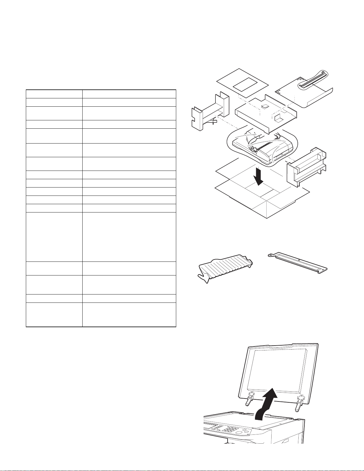
1. Unpacking
For unpacking, refer to the figure below.
2. Installation
RSPF glass coverIntermediate tray
Turn off the main switch of the copier and then remove the
power plug of the copier from the outlet.
1. Remove the platen cover.
Lift the platen cover and remove it from the copier.
AR-RP7 PRODUCT OUTLINE
– 1 –
Page 4
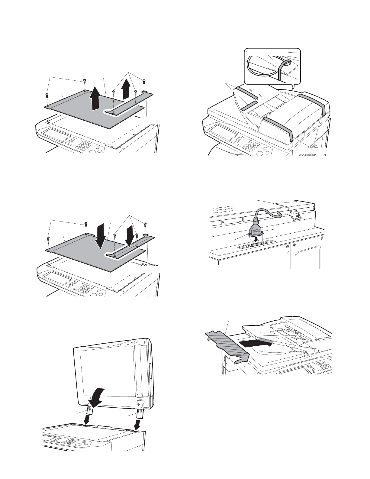
2. Remove the glass holders (right and left) and remove
r
r
the document glass.
Remove the right and left glass holders and remove the document
glass.
Remove the two screws (M3x8) of the left glass holder and the three
screws (M3x8) of the right glass holder.
5. Remove the filament tape.
Remove the filament tape located in the positions shown in the illustration.
Filament tape
Screws (M3x8)
Left glass
holder
Document glass
Screws (M3x8)
Right glass holde
3. Attach t he RSPF glass holder.
Insert the RSPF glass holder to the document glass.
Then, attach the document glass to the copier, fix the left glass holder
that has been removed in step 3 using two screws (M3x8), and fix the
RSPF glass using three screws (M3x8).
Screws (M3x8)
Left glass
holder
Document glass
Screws (M3x8)
Filament tape
Filament tape
6. Connect the relay connector.
Connect the Centronics connector of the RSPF t o the connector of t he
copier and then tighten the screws of the connector.
Screw
Screw
RSPF glass holde
4. Attach the RSPF.
Insert the hinge portion of the RSPF to the mounting portion of the
copier by holding the RSPF at an angle toward the rear side.
Hinge
Hinge
7. Attach the intermediate tray.
Insert the intermediate tray all the way into the RSPF.
Intermediate tray
AR-RP7 UNPACKING AND INSTALLATION
– 2 –
Page 5

Insert the power plug of the copier to the outle t and turn on
the main switch of the copier.
8. Adjust the RSPF white correcti on pixel.
• Open the RSPF and execute SIM 63-7 to adjust the RSPF auto white
correction pixel.
1) Open the SPF unit and press the START key.
SIMULATION 63-7
SHADING POSITION ADJUSTMENT. PRESS START.
2) Shading position adjustmen t is perfor m ed. (Cannot interrupt)
If the simu lat i on i s ex ec ut ed wi t h t he SPF uni t cl ose d, an er r or i s r es ult ed.
SIMULATION 63-7
SHADING POSITION ADJUSTMENT. EXECUTING...
3) [ ] indicates the order number of the pixel of the white sheet for SPF
exposure correction in the SPF position.
When the adjustment is completed normally, “COMPLETE” is displayed, and data are written into the EEPROM.
SIMULATION 63-7
SHADING POSITION ADJUSTMENT. COMPLETE.
[160]
3) Fold the A/4 (LTR) paper in half, set to the A5R (Invoice R) size,
adjust the guide and press the start key.
SIMULATION 53-6
SPF TRAY ADJUSTMENT.
INVR PAPER SET, AND PRESS START KEY.
4) Adjust the guide to the minimum width and press the start key.
SIMULATION 53-6
SPF TRAY ADJUSTMENT.
MIN POSITION SET, AND PRESS START KEY.
5) Make sure the indicator reads 60 before pressing the start key.
SIMULATION 53-6
SPF TRAY ADJUSTMENT. INPUT VALUE 1-99, AND PRESS
START.
60
6) Make sure the indicator reads 40 before pressing the start key.
SIMULATION 53-6
SPF TRAY ADJUSTMENT. INPUT VALUE 1-99, AND PRESS
START.
When the adjustment is completed abnormally, “ERROR” is displayed and data are not written into the EEPROM.
SIMULATION 63-7
SHADING POSITION ADJUSTMENT. ERROR.
[ 0]
*T he SP F white correct ion start pixel = Displayed pixel position -34.
9. Adjust the document guide width (Sim53-6)
Caution: If this adjustment is not performed, the document size display
remains special.
1) With the document guide opened to the full, set A/3 (A/4) (WLT (LT)
in the inch system) paper and adjust the guide.
Press the start key.
SIMULATION 53-6
SPF TRAY ADJUSTMENT.
WLT PAPER SET, AND PRESS START KEY.
2) Set to A4R (LTR) size, adjust the guide and press the start key.
SIMULATION 53-6
SPF TRAY ADJUSTMENT.
LTR PAPER SET, AND PRESS START KEY.
40
7) Make sure the document size is correctly shown in Sim2-2.
10. Check the copy magnification ratio.
• Set an original on the document glass and copy it.
Then, set an original in the document feeder tray and copy it.
• If the magnification ratio of the copy from the RSPF is different from
that of the copy from the document glass, carry out adjustment referring to the service manual.
11. Check the center displacement.
• Set an original on the document glass and copy it.
Then, set an original in the document feeder tray and copy it.
• If the center of the copy image from the RSPF is different from that of
the copy image from the document glass, carry out adjustment referring to the service manual.
12. Check the top end position.
• Set an original on the document glass and copy it.
Then, set an original in the document feeder tray and copy it.
• If the top end position of the copy image from the RSPF is different
from that of the copy image from the document glass, carry out
adjustment referring to the service manual.
13. Check the open/close detection position.
• If the open/close detection position measured with the open/close
detection position adjustment method described in the service manual does not conform to the specifications, carry out adjustment referring to the service manual.
Installation of RSPF is now complete.
AR-RP7 UNPACKING AND INSTALLATION
– 3 –
Page 6

Page 7
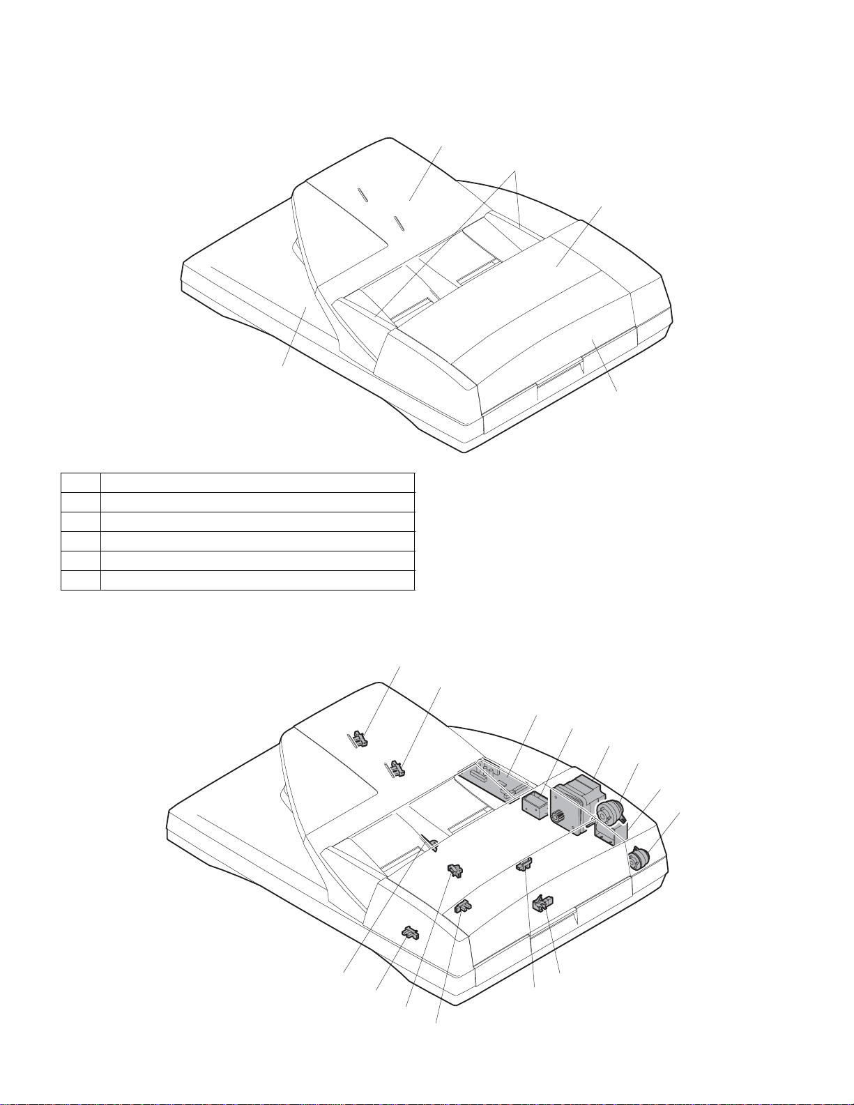
[4] EXTERNAL VIEW AND INTERNAL STRUCTURE
1. External view
1
2
5
3
4
No. Name
1 Document set tray
2 Document guide
3 Document feed section cover
4 Document transport section cover
5 Document exit section
2. Internal structure
11
10
9
8
7
3
5
6
14
12
1
2
AR-RP7 EXTERNAL VIEW AND INTERNAL STRUCTURE
– 4 –
4
13
Page 8
Sensor, detector, etc.
No. Code Name Type Function/Operation
1 EMPS Document set sensor Photo transmission Detects presence of documents.
2 FGOD Open/close sensor Photo transmission Detects open/close of the paper feed unit.
3 DFCL Paper feed clutch — —
4 DFD Paper entry sensor Photo transmission Detects presence of documents.
5 RSOL Pressure release solenoid — —
6 CLH Transport clutch — —
7 DTM SPF motor Stepping motor Drives document feed on the tray, transport, and paper exit roller.
8 GSOL Gate solenoid — —
9 — Interface PWB — —
10 DLS1 Document length detection SW (Short) Photo transmission Detects the document length on the tray .
11 DLS2 Document length detection SW (Long) Photo trans mission Detects the document length on the tray.
12 OPCLS Book sensor Photo transmission Detects the SPF float.
13 RDD Paper exit sensor Photo transmission Detects presence of documents.
14 SWD Document width sensor Volume Detects the document width on the tray.
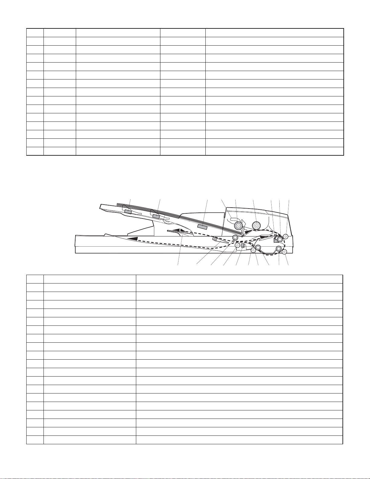
[5] OPEREATIONAL DESCRIPTIONS
1. Major parts of the paper feed section
8
12 43567
9
10 1918111314 151617 12
No. Part name Operation
1 Document length sensor (L2) Detects the document length on the tray.
2 Document length sensor (L1) Detects the document length on the tray.
3 Document set sensor Detects presence of documents.
4 Document width sensor Detects the document width.
5 Pickup roller Picks up documents.
6 Paper feed roller Feeds and transports documents.
7 Paper entry sensor (PAPER) Detects transport of documents.
8 PS roller Makes synchronization between the document lead edge and the image lead edge.
9 PS follower roller Makes synchronization between the document lead edge and the image lead edge.
10 Transpor t roller 2 Transports documents.
11 Transpor t follower roller 2 Transports documents.
12 Paper exit sensor (PO) Detects transport of documents.
13 Paper exit follower roller Discharges documents.
14 Paper exit roller Discharges documents.
15 Reverse gate Opens/closes the document reverse path.
16 Paper exit gate Separate document exit to the intermediate or the paper exit tray.
17 Intermediate tray Discharges documents to the intermediate tray during document reverse.
18 Transpor t roller 1 Transports documents.
19 Transpor t follower roller 1 Transports documents.
AR-RP7 OPEREATIONAL DESCRIPTIONS
– 5 –
Page 9
2. Out line of operations
[Duplex documents]
1) Document set (Document set senso r ON)
4
2) Document size detection (Document width sensors SWD the document width, and document length sensors L1, L2 detect the document length.)
4
3) Copier COPY key ON
4
4) RSPF motor ON
4
5) DFCL ON
4
6) Pickup roller and paper feed roller rotation
4
7) Paper entry sensor detects the document presence.
4
8) PS roller rotation
4
9) Copying (Front surface of document)
4
10) Transport roller rotation
4
11) Paper exit roller rotation
4
12) Paper exit gate falls down.
(Documents are discharged to the intermediate tray.)
4
13) Reverse gate falls down.
4
14) Paper exit roller reverse rotation
(Documents are fed to the reverse path.)
4
15) Paper entry sensor detects document presence.
4
16) PS roller rotation
4
17) Copying (Back surface of document)
4
18) Transport roller rotation
4
19) Paper exit roller rotation
4
20) Paper exit gate falls down
(Documents are discharged to the intermediate tray.)
4
21) Reverse gate falls down.
4
22) Paper exit roller reverse rotation
(Documents are fed to the reverse path.)
4
23) Paper entry sensor detects document presence.
4
24) PS roller rotation
4
25) Paper exit roller rotation
4
26) Paper exit gate lifts up.
4
27) Documents are fed to the paper exit tray.
4
28) Next document 3 (YES) 3 Go to 4).
4 (NO)
29) R SPF motor OFF
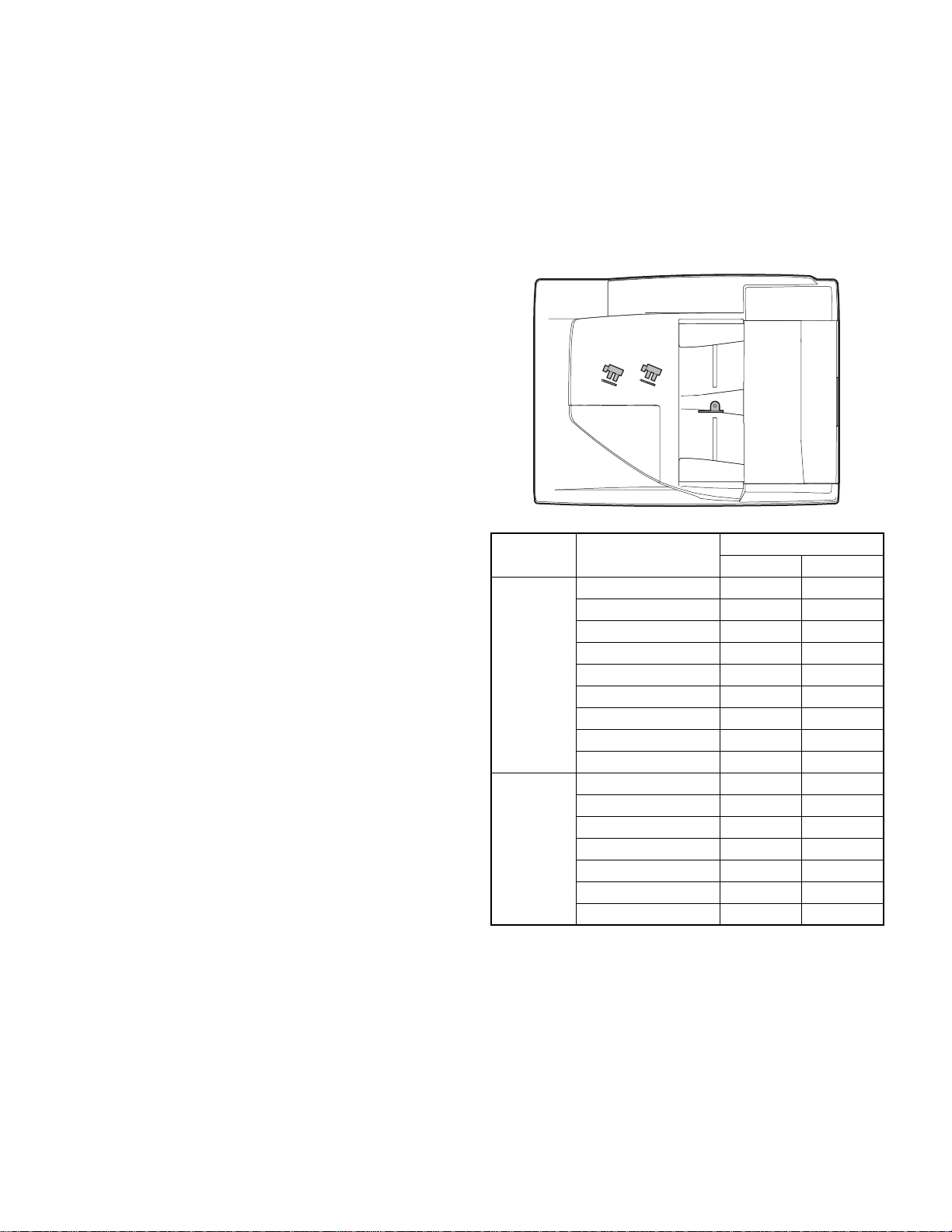
3. Document size detection
1) Document size detection with the document set tray
When documents are set on the document set tray in the auto selection
mode of paper/copy magnification ratio, the document size is detect ed
and paper and the copy magnification ratio are automatically selected.
When different sizes of documents are set, the max. size is detected.
The document width is detected by the document width sensors (SWD),
and the document length is detected by the document length sensors
(L1, L2) to identify the document size. Judgment of the document size is
made in a certain timing after detecting the document with the document set sensor (EMPS).
Document set size and
set direction
A5 nn
B5 nn
A5R nn
A4 nn
AB series
Inch series
Note: Detection sensor ON: o, OFF: n
B5R on
A4R on
8.5” x 13” oo
B4 oo
A3 oo
8.5” x 5.5” nn
8.5” x 5.5”R nn
11” x 8.5” nn
11” x 8.5”R on
8.5” x 13” oo
8.5” x 14” oo
11” x 17” oo
Document length sensor
L1 L2
AR-RP7 OPEREATIONAL DESCRIPTIONS
– 6 –
Page 10

Page 11
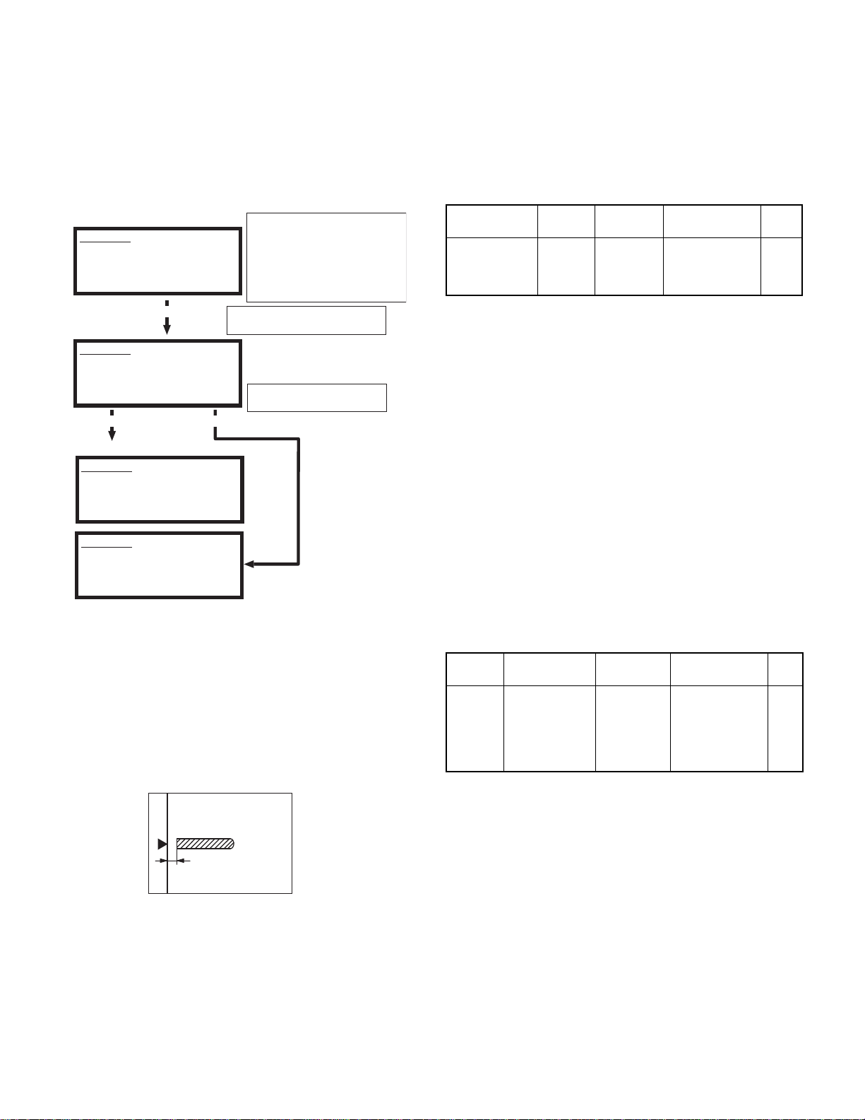
[6] ADJUSTMENTS
(1)RSPF auto white correction pixel
adjustment
[Function]
The white correction start pixel position is automatically adjusted.
This adjustment is performed after the lens unit is replaced.
[Operation]
(Initial screen)
SIMULATION 63-7
SHADING POSITION ADJUSTMENT. PRESS START.
Press the [START] key.
(During execution)
SIMULATION 63-7
SHADING POSITION ADJUSTMENT. EXECUTING...
Normal end Abnormal end
(Initial screen with the execution result displayed)
SIMULATION 63-7
SHADING POSITION ADJUSTMENT. COMPLETE.
[160]
SIMULATION 63-7
SHADING POSITION ADJUSTMENT. ERROR.
[ 0]
(2) RSPF magnification ratio adjustment
Note: • When performing this adjustment, check that the CCD unit is
properly installed.
• When performing this adjustment, check that the OC mode
adjustment in copying is completed.
1) Place a scale on the document table as shown below, and mak e a
normal copy to make a test chart.
Open the SPF unit and press the [START]
key. [ ] indicates the order number of
the pixel of the white sheet for SPF
exposure correction in the SPF position.
When the adjustment is completed
normally, "COMPLETE" is displayed,
and data are written into the EEPROM.
The SPF white correction start pixel
= Displayed pixel position - 34
If the simulation is executed with the
SPF unit closed, an error is resulted.
6) Enter the set value, and press the START key.
The entered correction value is stored and a copy is made.
7) Change the TEXT mode.
The TEXT lamp lights up, and the current correction value of the
back surface sub scanning direction magnification ratio is displayed
on the display section in two digits.
8) Enter the set value, and press the START key.
The entered correction value is stored and a copy is made.
<Adjustment specifications>
Mode Spec SIM Set value
Magnification
ratio adjustment
Normal:
m 1.0%
SIM 48-5
3: Surface
4: Back
Add 1:
Reduce 1:
0.1% increase
0.1% decrease
Set
range
1 ~ 99
(3) RSPF document off center adjustment
Note: When performing this adjustment, check that t he paper off-cen-
ter is properly adjusted.
1) Set the center position adjustment test chart (made by yourself) on
the RSPF.
<Adjustment specifications>
Draw a line in the center of paper. (In the scanning direction)
2) Make a normal copy from the manual feed tray, and compare t he
copy and the test chart.
If an adjustment is required, perform the following procedures.
3) Execute SIM 50-12.
4) The current off-center adjustment value is displayed on the display
section in two digits.
5) Enter the set value and press the START key.
The entered correction value is started and a copy is made.
<Adjustment specifications>
Mode Specification SIM Set value
Document
off-center
Simplex:
Center
Duplex:
Center
3.0mm
m
3.5mm
m
SIM 50-12
2: SPF surface
4: SPF back
Add 1:
0.1mm shifted to
R side.
Reduce 1:
0.1mm shifted to
L side.
Set
range
1 ~ 99
Note: Since the copy is used as the test chart, place the scale
in parallel to the front edge of the copy glass.
2) Set the test chart to the RSPF and make a normal copy.
3) Compare the copy and the test chart.
If an adjustment is needed, perform the following procedures.
4) Execute SIM 48-5.
5) The current correction value is displayed on the display section in
two digits.
AR-RP7 ADJUSTMENTS
– 7 –
Page 12
(4) RSPF image lead edge position adjustment
1) Set a scale on the OC table as shown below.
Note: Since the printed paper is used as the test chart, place the
scale in parallel to the front edge of the copy glass.
2) Make a copy, and use the copied paper as the document and make
a copy from RSPF again.
3) Check the copied paper. If an adjustment is required, perform the
following procedures.
4) Execute SIM 50-6.
5) Set the RSPF lead edge position set value so that the image similar
to the adjusted image at the OC image lead edge position
described previously is printed.
<Adjustment specifications>
Adjustment
mode
Image
lead edge
position
SIM Set value Specification
SIM 50-6 1step: 0.1mm shift Lead edge void:
1 ~ 4mm
Image loss:
3mm or less
Set
range
1 ~ 99
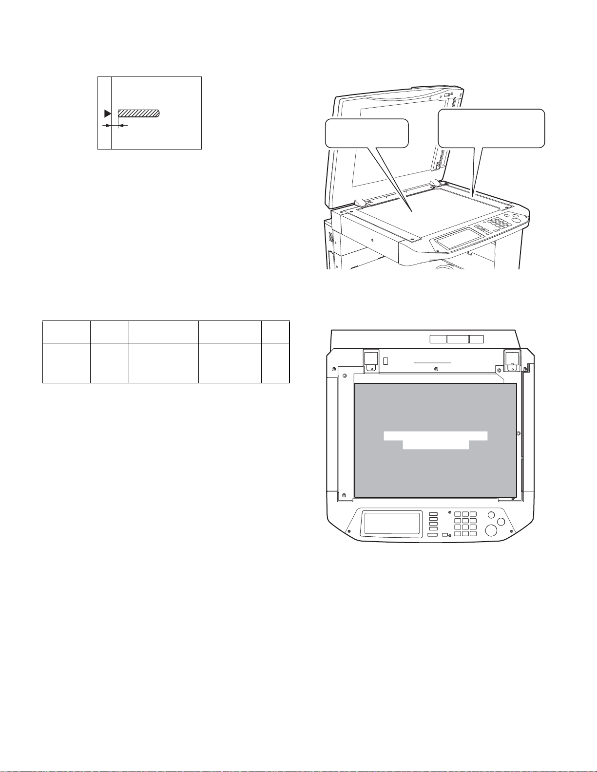
3) Check that the lead edge is not shifted. (Both surfaces)
(If the precedent lead edge adjustment was complete, the lead
edge follows automatically after changing the scan position.)
For the SPF standard
Place no other
things than the black
chart on the glass.
machine, check that the SPF
glass is covered completely
by the black chart.
(5) SPF scan position automatic adjustment
The SPF scan position is automatically adjusted.
1) With the SPF or the OC cover open, place a black background chart
on the OC glass. (The SPF standard model includes the SPF glass
surface.)
* Use a black chart UKOG-0011QSZZ, or make a chart as shown
below and use it.
Chart size: 310 x 470
Use a cutting sheet No. 791 (Black) or an equivalent for
making a chart.
Reason: To protect against erroneous detection caused by dis-
turbed lights of fluorescent lamps, etc.
2) Enter SIM 53-08, and press the COPY button.
Outline of SIM: The optical unit is moved to recognize the boundary
between the OS glass and the SPF glass. The SPF
scan position is automatically adjusted with the
boundary position as the reference.
Caution:
• A fter completion of the SPF scan position automatic adjustment,
perform the SPF lead edge adjustment (both surfaces).
• Place no other things than the black chart on the glass.
How to place the black chart
Cover this area.
• Since SPF scan is made around the center in the main scanning
direction, take care not to allow external lights to enter the section.
AR-RP7 ADJUSTMENTS
– 8 –
Page 13

[7] DISASSEMBLY AND ASSEMBLY
1. Document tray section
1) Document tray unit 2) Document length sensor
3
2
1
2
2
2
2
1
1
1
1
3
2
2
1
4
3
AR-RP7 DISASSEMBLY AND ASSEMBLY
3) Document width resistor PWB
3
1
2
– 9 –
Page 14

2. Paper feed unit section
1) Paper feed clutch
2) Pickup roller
3) Paper feed roller
1
1
3
2
2
1
1
1
1
3
2
2
AR-RP7 DISASSEMBLY AND ASSEMBLY
– 10 –
Page 15

4) Paper feed unit
1
6) Sensor
3
1
2
1
2
1
2
5) Separation sheet
3
AR-RP7 DISASSEMBLY AND ASSEMBLY
– 11 –
Page 16

3. Transport section
1) Transport unit
1
1
3) Pressure release solenoid
3
3
2
1
1
2
1
1
2
2
4) RSPF Motor
2
2) PS clutch
1
3
2
1
3
3
1
1
2
<Note for disassembling the motor>
The motor is positioned by the jig. Use the mark when assembling it
to the original position.
AR-RP7 DISASSEMBLY AND ASSEMBLY
– 12 –
Page 17

5) Transport roller
7) Sensor
1
3
2
3
1
2
1
3
2
6) Roller
1
2
8) Roller
1
1
1
1
4
1
2
3
1
4
2
3
AR-RP7 DISASSEMBLY AND ASSEMBLY
– 13 –
2
N
I
G
I
R
O
Page 18

9) Roller
3
1
4. Base section
1) Interface PWB
1
1
2
2
1
3) Book sensor
1
2
2
3
1
2) Solenoid
3
1
1
2
3
1
1
2
2
4) Sensor
1
2
1
AR-RP7 DISASSEMBLY AND ASSEMBLY
– 14 –
Page 19

[8] MAINTENANCE
1. Maintenance parts
No. Name Work item
1 Pickup roller Cleaning Yes Replace when
2-1 S eparat ion sheet Cleaning Yes Replace whe n
2-2 Front separation sheet Cleaning Yes Replace when
3 Paper feed roller Cleaning Yes Replace when
4 PS roller Cleaning Yes
5 Transp o rt roller Cleaning Yes
6 Paper exit roller Cleaning Yes
Service
call
3
1
Remark
worn down.
worn down.
worn down.
worn down.
2-2
2-1
5
6
4
7
(Note) When performing maintenance, refer to [7] DISASSEM BLY AND
ASSEMBLY.
AR-RP7 MAINTENANCE
– 15 –
Page 20

D
C
B
A
1
5V
234
L2
SENSOR
L1
5V
5V
W0
SPFCOVER
5V
5V
SPFOUT
SPFOPEN
5V
5V
SPF UN
SPF/RSPF
5V
PAPER
3.3V
SOL/CLU/Motor
WIDE SENSOR
24V
/CLH
24V
/PSLH
24V
/RSOL
24V
/GSOL
24V
MOTOR
(A, B, /A, /B)
2 1
3
5
Data
Selector
AMP
5V
24V
ARRAY
TRANSISTOR
MOTOR
DRIVER
24V
5 4
678
7 6
YSPF
SEL(A#, B#, C#)
Andromeda SPF/RSPF INTERFASE
1. Block diagram
(OPTION INTERFASE PWB) 5V 5V
PAPER
SPFFWS
PDOWNA
PDOWNB
SPF
(MODA, MODB,
/MODA, /MODB)
SPF
(CLH, PSLH, RSOL, GSOL)
8
[9] ELECTRICAL SECTION
D
C
B
A
AR-RP7 ELECT R I C AL SECTION
– 16 –
Page 21

B
B
B
D
D
D
D
12345678
12345678
12345678
12345678
Document set
sensor
Pickup unit
open/close
sensor
C
C
C
C
PAPER
(Paper entry
sensor)
B
A
GP1S73P
W0
SGND
VCC
213
179228-3
179228-3
PLORGY
LBGYOR
<PF UN harness>
21354
W0
SGND
VCC
PLGYORLBGY
GP1S73P
PAPER FEED UNIT
COVER
SGND
VCC
213
66
COVER
SGND
VCC
45312
SMP-06V-NC SMR-06V-N
OR
<SPF harness/
RSPF harness>
15326
Paper feed
clutch
BL
BL
SMR-02V-B
24V1 11
/PSOL 22
SMP-02V-BC
RD
BR
4117
OS-655203
SGND
VCC
213
B3B-PH-K-S
ORGYPL
PULSE
PAPER
A1
/A3
24V12
XHB-6
BLRDLBPLRDPKBRGYOR
MOTOR
/B6
B4
24V15
10
179228-3
13
GP1S73P
SGND
SPFOPEN
VCC
213
SPFOPEN
(Book sensor)
SMP-03V-NC SMR-03V-N
RD
SPF PS CLH
BL
BL
SPFRSOL
BL
BL
1
3
24V11
/CLH3
N.C22
BR
2
11
/RSOL
24V1
2
SMP-02V-NC SMR-02V-N
RD
LB
SPFGSOL
BL
BL
GP1S73P
/SPFOUT
(Paper exit sensor)
SGND
/SPFOUT
VCC
213
179228-3
BRGYOR
<Paper exit sensor harness>
21
21
21
21
3
3
3
3
2. Actual wiring diagram
SPF Interface PWB
YSPF
SGND
SELA#
SPFMODB
SELB#
/SPFMODB
123456789
B26B-PHDSS-B (CN1)
<SPF Interface harness>
15
SUB-25
D
SGND 16
SELA# 20
SPFMODB 17
SELB# 7
/SPFMODB 3
YSPF
Copier (Main body)
Option connector PWB
W0
SGND
VCC
COVER
SGND
VCC
/PSOL
24V1
3.3V 19
SPFGSOL
SPFMODA
SPFGSOL 22
SPFMODA 5
VCC 16
SPFRSOL
/SPFMODA
SPFRSOL 9
/SPFMODA 4
SPFCLH
SPFCLH 21
B24B-PHDSS-B (CN2)
SELC#
N.C
24V
SGND
PGND
SPFWS5V3.3V
1011121314151617181920212223242526
SELC# 6
N.C -
24V 12
SGND 13
PGND 25
SPFWS 18
5V 24
SGND 14
PAPER 18
A17
PDOWNA
SPFPSOL
PDOWNA 8
SPFPSOL 10
/A 19
24V1 8
PDOWNB
SPFPAPER
PDOWNB 23
SPFPAPER 11
/B 23
B21
24V1 9
PGND
SGND
24V
26
FG
PGND 14
SGND 1
24V 2
24V1
/CLH
SGND 20
SPFOPEN 24
VCC 22
/RSOL 15
24V1 12
SRA-21T-4
<SPF PWB earth cord>
GY
SRA-21T-4
SRA-21T-4
GY
SRA-21T-4
<U-turn earth harness>
L13
SGND5
B10B-PHDSS (CN2)
LBGYORPLGYORGYBRBL
SPF UNIT FG
<Document tray harness>
179228-3
L1
24V1 1
/GSOL 2
B2B-PH-K-S (CN4)
VCC1
VCC2
L24
SGND6
312
179228-3
VCCL1SGND
GP1S73P
SGND
7
GP1S73P
L2
3.3V
SPFWS
9
10
312
VCCL2SGND
SGND 2
/SPFOUT 1
B3B-PH-K-S (CN3)
8 N.C
321
3.3V
SPFWS
SGND
321
GY
BR
BL
321
Paper width
volume PWB
VCC 3
SMP-03V-NC
ORIGINAL TRAY
SMR-03V-N
SIN-002T-1.0
87654
87654
87654
87654
B
B
B
D
D
D
D
C
C
C
C
B
A A
A A
A A
A
AR-RP7 ELECT R I C AL SECTION
– 17 –
Page 22

B
B
B
C120
0.047u/50V
C3
+
C119
B
47u/35V
0.047u/50V
IC2
24V1
VSA
VSB
SYNCA
SYNCB
OUTA
OUT A
OUTB
OUT B
RSA
OUT/B
OUT/A
OUT /A
OUT /B
REFA
REFB
RSB
D106D1FL20U
D105D1FL20U
GNDA
GNDB
In /A
In A
In /B
In B
D104D1FL20U
D103D1FL20U
SELC#
SELB#
SELA#
C
C
C
C
C115
1000p/50V
IC101
SPFWS#
D102
DA204K
LMV358
+
-
C102
0.1u
R101
100K
SPFWS
D
D
D
D
/PSOL
/CLH
/RSOL
/GSOL
ZD1
C125
0.047u/50V
C126
0.047u/50V
Z1015
IC1
1B 1C
SPFPSOL
2B 2C
3B 3C4B5B4C6B5C7B6CGND
SPFCLH
SPFRSOL
SPFGSOL
YSPF
7C
COM
TD62003AP
12345678
12345678
12345678
12345678
A
21
21
21
21
3
3
3
3
SLA7032M
VCC
IC102
D0D1D2D3D4D5D6D7ABC
R117
20K
R118
20K
R111
20K
R105
20K
R104
20K
R103
20K
C114
1000p/50V
C113
1000p/50V
ZD101
UDZ5.6
C110
0.1u/25V
Y
W
GND
G
74HC151
C111C109
C105C104 C106
ZD104
UDZ5.6
ZD103
UDZ5.6
ZD102
UDZ5.6
JP1
DSPF
C118
0.1uF/25V
C121
R2 1(2W)
R126 2.4k
R122
620F
TP103
$PIN0
0.1uF/25V
R1 1(2W)
SPFMODB
SPFMODA
/SPFMODB
+
10K
10K
/SPFMODA
R128
200F
Q101 DTC114EKA
10K
10K
C1
10u/16V
C122
0.1u/25V
Q102 DTC114EKA
R127 2.4k
R131
680F
$PIN0
TP102
R123
10K
R132
200F
$PIN0
TP101
R102
20K
3-1. Interface PWB (1/2)
3. Circuit Diagram
D
D
D
D
W0
SPFOPEN
/SPFOPEN
/SPFCOVER
R124
10K
L L L /SPFCOVER
L L H SPFOPEN
L H L SPFOUT
LHHW0
HL LL1
HL HL2
H H L SPF(H)/DSPF(L)
SELC SELB SELA Y
C103
L1
L2
Sensor matrix
C
C
C
C
H H H /SPFDTC(L)
87654
87654
87654
87654
PDOWNB
PDOWNA
B
B
B
B
A A
A A
A A
A
AR-RP7 ELECT R I C AL SECTION
– 18 –
Page 23

B
B
B
R114
B
/SPFOUT
0.1u/25V
C101
R110
110
110
123
CN3
B3B-PH-K-S
D
D
D
D
12345678
12345678
12345678
12345678
110
R134
110
R133
R130
110
R129
110110
110
R119
R125
CN5
24V1
R120
110
R121
5V
110
C
C
C
C
C117
C116
0.1u
8
0.1u
PAPER
10121416182022
/SPFCOVER
246
13579111315171921
SPFOPEN
C123
C124
24
23
B24B-PHDSS-B
0.1u
0.1u
5V
A
21
21
21
21
3
3
3
3
3.3V
W0
SPFWS
/SPFMODB
SPFMODA
SPFMODB
246
CN1
135791113151719212325
/SPFMODA
SPFMODA
/SPFMODA
8
101214161820222426
/PSOL
PDOWNB
PDOWNA
PDOWNA
PDOWNB
/CLH
/RSOL
24V1
OUTA
OUTB
OUT/A
OUT/B
10K
R109
10K
R108
10K
R107
10K
R106
B26B-PHDSS
+
C108
C107
C2
0.047uC112
0.047u
0.1u/25V
10u/16V
L2
3.3V
R113
110
R112
110
246
8
10
CN2
13579
B10B-PHDSS-B
R115
110
R116
110
5V
L1
SPFWS
1
2
CN4
24V1
B2B-PH-K-S
/GSOL
3-2. Interface PWB (2/2)
D
D
D
D
YSPF
SELA#
SELB#
SELC#
5V
SPFGSOL
PAPER
SPFCLH
SPFRSOL
SPFPSOL
C
C
C
C
AR-RP7 ELECTRICAL SECTION
– 19 –
87654
87654
87654
87654
B
B
B
B
A A
A A
A A
A
Page 24

4. Parts arrangement
a. Parts surface
CN3 (B3B-PH-K-S)
/SPFOUT1
SGND2
VCC3
CN4 (B2B-PH-K-S)
24V11
/GSOL2
b. Solder surface
10
11
CN5 (B24B-PHDSS-B)
1
2
3
4
5
6
7
W0
COVER
VCC
VCC
SGND
SGND
24V1
24V18
24V19
24V1
/PSOL
24V112
13
SPFOPEN24
/CLH
SGND14
/RSOL15
PAPER18
SGND20
CN2 (B10B-PHDSS)
1
VCC
VCC2
VCC16
A17
/A19
B21
VCC22
/B23
7
8 N.C
9
10
L13
L24
SGND5
SGND6
SGND
SPFWS
3.3V
10
11
12
13
CN1 (B26B-PHDSS-B)
1
YSPF
2
SGND
3
SELA#
4
SPFMODB
5
SELB#
6
/SPFMODB
7
SELC#
8
9
N.C
24V
SGND
PGND
SPFWS
5V
14
15
16
17
18
19
20
21
22
23
24
25
26
3.3V
SPFGSOL
SPFMODA
SPFRSOL
/SPFMODA
SPFCLH
PDOWNA
SPFPSOL
PDOWNB
SPFPAPER
PGND
SGND
24V
AR-RP7 ELECTRICAL SECTION
– 20 –
Page 25

q
PARTS GUIDE
CODE:00ZARRP7//P1/
デジタル複合機
デジタル複合機
デジタル複合機デジタル複合機
両面原稿自動送り装置
両面原稿自動送り装置 (RSPF)
両面原稿自動送り装置両面原稿自動送り装置
Digital Copier
Reverse Pass Feeder(RSPF)
MODEL
このパーツガイドに掲載されている表示価格ランクは消費税抜きです。
CONTENTS
1
外装部 1(Exteriors 1)
2
外装部 2(Exteriors 2)
3
給紙部 (Paper feeding section)
4
搬送部 1(Transport section 1)
5
搬送部 2(Transport section 2)
6
梱包&付属品 (Packing material & Accessories)
7
SPF 中継基板 (SPF interface PWB unit)
AR-RP7
■
索引 (Index)
本書はサービス活動用に作成した資料です。
一部内容が製品の改良・改善等により予告
なしに変わることがあります。
SHARP CORPORATION
This document has been published to be used for
after sales service only.
The contents are subject to change without notice.
Page 26

補修部品のランク付
市場における補修部品の在庫管理が、適正に運営出来る手助けとなることを、目的とします。
Aランク : メンテナンスパーツ、メンテナンスパーツには入っていないがメンテナンスパーツに近い消耗パーツ。
Bランク : 性能・機能パーツ(センサー、クラッチ等の電気パーツ)、消耗パーツ。
Eランク : 基板含むユニットパーツ。
Dランク : 整備パーツ(外装、パッキング、同梱パーツ)。
Cランク : 上記ランク以外のパーツ(基板の子部品を除いたもの)。
DEFINITION
Rank A : Maintenance parts, and consumable parts which are not included in but closely related to maintenance parts
Rank B : Performance/function parts (sensors, clutches, and other electrical parts), consumable parts
Rank E : Unit parts including PWB
Rank D : Preparation parts (External fitting, packing, parts packed together)
Rank C : Parts other than the above (excluding sub components of PWB)
安全性・信頼性確保のため部品は、必ず正規のものをご使用下さい。
! 印の商品は、安全上重要な部品です。交換をする時は、安全及び性能維持のため必ず指定の部品をご使用下さい。
Because parts marked with "!" is indispensable for the machine safety maintenance and operation, it must be replaced with
the parts specific to the product specification.
F
当モデルのサービス資料には、この資料以外にサービスマニュアル ( 回路図含む ) があります。合わせてご利用下さい。
F Other than this Parts Guide, please refer to documents Service Manual(including Circuit Diagram)of this model.
F Please use the 13 digit code described in the right hand corner of front cover of the document, when you place an order.
F For U.S. only-Use order codes provided in advertising literature. Do not order from parts department.
– 1 –
Page 27

1
外装部 1(Exteriors 1)
NO. PARTS CODE
1 GCAB-0075QSZZ AR EQ N D
2 XEBSE40P12000 AA DD C
3 XHBSE30P08000 AA DD C
4 LSTPP0016QSZZ AC DJ N C
5 PCLC-0017QSZZ AT EZ N B
6 NPLYZ0033QSZZ AD DJ N B
7 CGIDM0106RS51 BL HR N E
8 XHBSD30P10000 AA DD C
9 GCAB-0074QSZZ AK DX N D
10 MHNG-0021QSZZ AX FG N C
11 MHNG-0022QSZZ AX FG N C
12 XWVSD40-05000 AA DD C
13 NBRGC0018QSZZ AD DJ C
14 LSOU-0037QSZZ BE GN N C
15 PCUSS0022QSZZ AW FG C
16 PSHEZ0413QSZZ AD DJ N C
17 PSHEZ0077QSZ1 AE DJ C
18 XEBSE30P08000 AA DD C
19 LPLTP0321QSZZ AE DS N C
20 GCAB-0078QSZZ AV FG N D
21 LSOU-0039QSZZ AN EG N C
22 MLEVP0098QSZZ AC DJ N C
23 VHPGP1S73P+-1 AF DS B
24 CPWBF1501FCE2 AS EQ N E
25 NGERP0168QSZZ AD DJ N C
26 NGERR0169QSZZ AE DS N C
27 MSPRC0250QSZZ AC DJ C
28 PTME-0271FCZZ AD DJ C
29 XEPSD30P08X00 AA DD C
30 MSPRP0315QSZZ AD DJ N C
31 LSOU-0038QSZZ AW FG N C
32 LSOU-0041QSZZ AP EQ N C
33 LPLTP0319QSZZ AH DX N C
34 LPLTP0320QSZZ AH DX N C
35 DHAI-0386QSZZ AK DX N C
501 CSOU-0037RS51 BQ LP N E
502 CSOU-0038RS51 BF GN N E
PRICE RANK
Ex. Ja.
NEW
MARK
PART
RANK
Rear exterior 後キャビネット
Screw(4×12) ビス
Screw(3×8) ビス
Stopper ストッパー
SPF paper feed clutch SPF 給紙クラッチ
Coupling pulley(39P) カップリングプーリー
SPF Transport unit 搬送ユニット RSPF
Screw(3×10) ビス
Front exterior 前キャビネット
SPF hinge L SPF ヒンジ L
SPF hinge R SPF ヒンジ R
Washer キクワッシャー
Bearing 軸受
Base tray ベーストレイ
OC mat OC マット
OC mat sheet R OC マットマイラー R
OC mat sheet F OC マットマイラー F
Screw(3×8) ビス
Sensor plate 幅検知センサー取付板
Original tray lower exterior 原稿トレイ下キャビネット
Original tray S 原稿トレイ S
Original detect actuator 原稿検知アクチュエーター
Photo sensor(GP1S73P) フォトセンサー
SPF VR PWB unit SPF VR PWB
Gear(36T) 幅検知ピニオン 36T
Gear 幅検知ラック TLP
Tray lock spring トレイロックスプリング
Tray lock pawl トレイロック爪
Screw(3×8) ビス
Regulation plate spring 規制板スプリング
Original tray 原稿トレイ
Middle tray 中間トレイ
Regulation plate F 規制板 F
Regulation plate R 規制板 R
Original tray harness 原稿トレイハーネス
Base tray unit(Include Block 2-501) ベーストレイユニット
Original tray unit 原稿トレイユニット
DESCRIPTION
( ブロック 2-501 含む )
1
外装部 1(Exteriors 1)
22
23
35
22
23
21
18
29
26
33
24
27
28
25
19
2
1
3
2
8
4
5
6
7
13
2
34
2
35
31
32
10
9
12
2
12
501
11
12
2
26
30
29
17
16
14
12
2
2
502
18
20
18
18
– 2 –
15
18
PRP01719
Page 28

2
外装部 2(Exteriors 2)
NO. PARTS CODE
1 CPWBF0139QSE1 BA FX N E
2 XHBSE30P08000 AA DD C
3 DHAI-0382QSZZ BA FX N C
4 LPLTM0111QSZZ AC DJ C
5 RPLU-0011QSZ1 AQ EQ B
6 PSPO-0023QSZZ AB DJ C
7 PSPO-0004QSZZ AB DJ C
8 RCORF0026FCZZ AL EB C
9 MSPRD0342QSZZ AD DJ N C
10 MLEVP0036QSZZ AD DJ C
11 MLEVF0093QSZZ AE DJ N C
12 XBBSD30P05000 AA DD C
13 DHAI-0388QSZZ AE DS N C
14 MSPRD0211QSZZ AC DJ C
15 VHPGP1S73P+-1 AF DS B
16 MLEVP0092QSZZ AC DJ N C
17 XRESP20-04000 AA DD C
18 NROLP0011QSZZ AD DJ B
19 PSPO-0020QSZZ AB DJ C
20 PSHEZ0285QSZZ AB DJ C
21 NSFTZ0013QSZZ AF DS C
22 PSPO-0003QSZZ AC DJ C
23 LHLDZ0101QSZZ AE DS N C
24 MSPRD0305QSZZ AC DJ N C
25 LPINS0327FCZZ AC DJ C
26 NSFTZ0072QSZZ AP EQ N C
27 XRESP50-06000 AA DD C
28 NBRGM0501FCZZ AB DJ C
29 NSFTZ0009QSZZ AE DS C
30 NROLP0010QSZZ AD DJ B
31 MSPRP0306QSZZ AC DJ N C
32 LPLTM0316QSZZ AH DX N C
33 XEBSE30P08000 AA DD C
34 MSPRC0307QSZ1 AC DJ N C
35 MSPRP0123QSZZ AD DJ C
36 MSPRT0308QSZZ AC DJ N C
37 PSHEZ0436QSZZ AD DJ N C
38 PSHEZ0069QSZZ AE DJ C
40 LPLTP0117QSZZ AM EG C
41 NBRGP0041GCZZ AD DJ C
42 PRNGP0090FCZZ AA DJ C
43 LSOU-0037QSZZ BE GN N C
501 CSOU-0037RS51 BQ LP N E
PRICE RANK
Ex. Ja.
NEW
MARK
PART
RANK
SPF interface PWB unit SPF 中継 PWB
Screw(3×8) ビス
SPF interface harness SPF 中継ハーネス
Reinforce plate earth 補強板アース
Gate solenoid ゲートソレノイド
Sound proof Sponge 消音スポンジゲート
Delivery gate sponge 排紙ゲート用スポンジ
Core(TRC-16813) コア
Delivery gate spring 排紙ゲートスプリング
Delivery gate lever 排紙ゲートレバー
Pressure release lever 圧解レバー
Screw(3×5) ビス
Paper exit sensor harness 排紙センサーハーネス
Delivery sensor ACT spring 排紙センサー ACT スプリング
Photo sensor(GP1S73P) フォトセンサー
Delivery sensor ACT lever 排紙センサー ACT レバー
E type ring E リング
Delivery roller 排紙従動ローラー
Sponge ケイタシスホンシ LPD
Sound proof sheet 排紙従動消音シート
Delivery shaft 排紙従動軸
Sound proof Sponge 圧解消音スポンジ
Pressure release holder 圧解ホルダー
Delivery spring 排紙従動スプリング
SP pin(2×10) SP ピン
Pressure release shaft 圧解軸
E type ring E リング
Metal D メタル D N
Transport shaft 搬送従動軸
Transport roller 搬送従動ローラー
Spring 読取前従動スプリング
Base tray reinforce plate ベーストレイ補強板
Screw(3×8) ビス
Earth spring 読取前アーススプリング
Transport spring 搬送従動スプリング
Transport earth spring 排紙従動アーススプリング
Sheet 読取前マイラー
Base tray sheet ベーストレイマイラー
Delivery gate 排紙ゲート
Bearing 軸受
Ring(E5) 樹脂製リング
Base tray ベーストレイ
Base tray unit(Include Block 1-501) ベーストレイユニット
DESCRIPTION
( ブロック 1-501 含む )
3
給紙部 (Paper feeding section)
NO. PARTS CODE
1 GCAB-0076QSZZ AP EQ N D
2 NGERH0166QSZZ AC DJ N C
3 PCLC-0316FCZ1 AR EQ B
4 MLNKP0001QSZZ AD DJ N C
5 MSPRD0309QSZZ AC DJ N C
6 NGERH0167QSZZ AD DJ N C
7 NBRGM0096FCZ1 AC DJ C
9 XRESP50-06000 AA DD C
10 NSFTB0075QSZZ AF DS N C
11 XPSSP20-07000 AA DD C
12 LPLTM0318QSZZ AC DJ N C
13 XEBSE30P08000 AA DD C
14 MSPRD0314QSZZ AD DJ N C
15 NSFTZ0074QSZZ AF DS N C
17 NBRGC0018QSZZ AD DJ C
18 NPLYZ0033QSZZ AD DJ N B
19 PCLC-0017QSZZ AT EZ N B
20 MARMM0047QSZZ AE DJ N C
21 LSTPP0016QSZZ AC DJ N C
22 DHAI-0390QSZZ AC DJ N C
23 PGIDM0105QSZZ AQ EQ N C
24 GCAB-0077QSZZ AQ EQ N D
26 MSPRP0311QSZZ AC DJ N C
27 PTME-0029QSZZ AE DS N C
28 MSPRD0310QSZZ AC DJ N C
29 NROLP0010QSZZ AD DJ B
30 NSFTZ0009QSZZ AE DS C
31 MARMP0046QSZZ AD DJ N C
32 PCOVP0094QSZZ AD DJ N C
34 CSFTB0073QS01 AF DS N E
35 MARMP0044QSZZ AF DS N C
PRICE RANK
Ex. Ja.
NEW
MARK
PART
RANK
Open and shut exterior 開閉キャビネット
Paper feed shaft gear(20T) 給紙軸ギヤ
Torque limiter 分離ローラートルクリミッタ
Pickup link 呼び込みリンク
Pickup arm spring 呼び込みアームスプリング
Paper feeding drive gear(32T) 給紙駆動ギヤ
Bearing 軸受
E type ring E リング
Paper feed roller shaft 給 紙ローラー軸
Spring pin(φ2-7) スプリングピン
Paper feeding earth plate 給紙アース板
Screw(3×8) ビス
JAM release spring R JAM 解除スプリング R
PF roller shaft 給紙入力軸
Bearing 軸受
Coupling pulley(39P) カップリングプーリー
SPF paper feed clutch SPF 給紙クラッチ
U-turn PG arm R U ターン PG アーム R
Stopper ストッパー
U-turn earth harness U ターンアースハーネス
U-turn guide U ターン PG TLPD
U-turn PG exterior U ターン PG キャビネット
PS spring PS 従動テンションプリング
U-turn PG lock pawl U ターン PG ロック爪
U-turn PG lock spring U ターン PG ロックスプリング
Transport roller 搬送従動ローラー
Transport shaft 搬送従動軸
U-turn PG arm F U ターン PG アーム F
Maintenance cover メンテカバー
Pickup roller shaft ASSY' 呼び込みローラー軸組品
Pickup arm 呼 び込みアーム
DESCRIPTION
– 3 –
Page 29

3
給紙部 (Paper feeding section)
NO. PARTS CODE
PRICE RANK
Ex. Ja.
NEW
MARK
36 LFRM-0069QSZZ AQ EQ N C
37 NCPL-0049FCBZ AT EZ C
38 NPLYZ0035QSZZ AD DJ N B
39 NROLR1311FCZZ AN EG B
40 NROLR1312FCZZ AN EG B
41 NPLYZ0034QSZZ AD DJ N B
42 NBLTT0033QSZZ AF DS N B
43 VHPGP1S73P+-1 AF DS B
44 DHAI-0387QSZZ AH DX N C
46 MLEVP0097QSZZ AC DJ N C
47 LSTPP0015QSZZ AC DJ N C
48 MLEVP0096QSZZ AC DJ N C
49 MARMP0045QSZZ AC DJ N C
50 MSPRD0313QSZZ AC DJ N C
501 CCAB-0077RS51 AZ FQ N E
(Unit)
901 CFRM-0069RS51 BK HC N E
PART
RANK
DESCRIPTION
Paper feeding frame 給紙フレーム
Coupling カップリング
Paper feeding roller pulley(16P) 給紙ローラープーリー 16P
Paper feed separation roller 給紙分離ローラー
Pickup roller 呼び込みローラー
Pick up roller pulley(16P) 呼込みローラープーリー 16P
Drive belt 駆動ベルト
Photo sensor(GP1S73P) フォトセンサー
PFUN harness PFUN ハーネス
Original detect actuator 原稿検知アクチュエーター
Stopper ストッパー
Stopper release lever ストッパー解除レバー
Stopper arm ストッパーアーム
JAM release spring F JAM 解除スプリング F
U-turn PG uint U ターン PG ユニット
Paper feeding unit 給紙ユニット
2
外装部 2(Exteriors 2)
40
44
39
501
PRP01720
3
給紙部 (Paper feeding section)
3
8
43
38
2
2
4
37
20
19
18
17
24
1
1
7
41
42
20
21
22
27
28
5
12
6
12
11
10
9
13
15
24
23
14
16
17
18
19
29
25
30
27
26
30
36
35
33
29
28
33
33
30
31
34
32
33
43
44
901
2
3
4
5
49
9
49
46
50
13
42
40
47
48
47
43
44
41
39
48
36
45
7
9
37
38
6
7
13
34
35
11
10
14
13
13
12
13
13
32
9
7
18
17
15
31
13
13
13
30
29
27
28
21
19
20
23
29
26
26
13
22
24
13
13
501
PRP01721
– 4 –
Page 30

4
搬送部 1(Transport section 1)
NO. PARTS CODE
1 PGIDM0107QSZZ AP EQ N C
2 PSHEZ0452QSZZ AP EQ N C
4 PSHEZ0423QSZZ AC DJ N C
5 LPLTP0328QSZZ AC DJ N C
7 PSHEZ0451QSZZ AC DJ N C
9 LPLTM0327QSZZ AD DJ N C
11 XHBSE30P08000 AA DD C
12 NROLR0096QSZZ AR EQ N B
13 NROLR0094QSZZ AR EQ N B
14 NROLR0095QSZZ AR EQ N B
15 PSHEZ0415QSZZ AE DS N C
16 LPLTM0325QSZZ AH DX N C
17 MSPRC0063QSZZ AB DJ C
18 DHAI-0384QSZZ AR EQ N C
19 RDTCT0006QSZZ AL EB B
20 PTME-0030QSZZ AC DJ N C
22 NBRGM0501FCZZ AB DJ C
23 XRESP50-06000 AA DD C
24 XPSSP20-09000 AA DD C
25 NPLYZ0019QSZZ AE DJ B
26 PSHEP3029FCZZ AA DD C
27 LHLDZ0102QSZZ AC DJ N C
28 XEBSE30P08000 AA DD C
29 NKOM-0007QSZZ AC DJ N C
30 MLEVP0095QSZZ AD DJ N C
32 VHPGP1S73P+-1 AF DS B
33 XEBSE40P14000 AA DD C
34 MSPRC0153QSZZ AB DJ C
35 XWVSD40-05000 AA DD C
36 LPLTP0131QSZZ AD DJ C
37 JKNBZ0009QSZZ AE DJ N D
38 NBLTT0036QSZZ AF DS N B
39 NBRGC0017QSZZ AC DJ C
40 MSPRD0316QSZZ AC DJ N C
41 LPLTP0324QSZZ AH DX N C
42 NROLR0097QSZZ AR EQ N B
43 LPLTM0326QSZZ AM EG N C
44 PBRSS0008QSZ1 AH DX B
45 PGIDM0106QSZZ AS EQ N C
46 PSHEZ0454QSZZ AB DJ N C
47 PSHEZ0455QSZZ AD DJ N C
501 CGIDM0106RS51 BL HR N E
PRICE RANK
Ex. Ja.
NEW
MARK
PART
RANK
Paper feeding guide 給 紙ガイド
Front separate sheet 前捌きシート
Separate sheet 捌きシート
SPF separate plate SPF 捌き板
Sound proof sheet 前捌き消音シート
Silence plate 消音プレート
Screw(3×8) ビス
Transport roller 搬送ローラー
PS roller PS ローラー
Read roller 読取前ローラー
White sheet 白マイラー
Transport plate 搬送板
Delivery paper guide spring 排紙 PG- スプリング
RSPF harness RSPF ハーネス
Inlet detect sensor 入紙検知センサー
Open and shut lock pawl 開閉ロック爪
Metal D メタル D N
E type ring E リング
Spring pin(φ2-9) スプリングピン
PS pulley PS プーリー
Flange sheet DUP2 フランジマイラー DUP2
Tension holder F テンションホルダー F
Screw(3×8) ビス
Tension roller テンションコロ
Book sensor actuator ブックセンサーアクチュエーター
Photo sensor(GP1S73P) フォトセンサー
Screw(4×14) ビス
Book sensor spring ブックセンサースプリング
Washer キクワッシャー
Book sensor attachment plate ブックセンサー取付板
JAM release knob(24P) JAM 解除ノブ
Belt(B79MXL4.0) ベルト
Bearing 軸受
Tension spring F テンションスプリング F
Reverse gate plate 反転ゲート板
Delivery roller 排紙ローラー
Paper feeding PG reinforce plate 給紙 PG 補強板
Discharge brush 除電ブラシ N
Transport R guide 搬送 R PG
PF PG cushion R 給紙 PG クッション R
PF PG sound proof cushion 給紙 PG 消音クッション
SPF Transport unit(Include Block 5-501,Without No.9,10,18) 搬送ユニット RSPF
DESCRIPTION
( ブロック 5-501 含む。
No.9,10,18 除く )
5
搬送部 2(Transport section 2)
NO. PARTS CODE
1 RMOTS0043QSZZ BG GT N B
2 DHAI-0384QSZZ AR EQ N C
3 PTPE-0018QSZZ AC DJ C
4 XEBSE30P08000 AA DD C
6 RPLU-0015QSZ1 AR EQ B
7 PSPO-0022QSZZ AB DJ C
8 XRESP40-06000 AA DD C
9 PSHEZ0414QSZZ AB DJ N C
10 NBLTT0034QSZZ AF DS N B
11 NGERH0170QSZZ AD DJ N C
12 NBRGM0501FCZZ AB DJ C
13 NGERH0116QSZ1 AD DJ C
14 XEPSD30P08X00 AA DD C
15 NGERH0117QSZZ AK DX C
16 XPSSP20-09000 AA DD C
17 NPLYZ0019QSZZ AE DJ B
18 NBLTT0035QSZZ AE DS N B
19 PSHEP3029FCZZ AA DD C
20 XRESP50-06000 AA DD C
21 MSPRP0312QSZZ AD DJ N C
22 XHBSE30P08000 AA DD C
23 NBRGC0017QSZZ AC DJ C
24 NPLYZ0018QSZZ AE DJ B
25 PCLC-0018QSZZ AT EZ N B
26 NKOM-0007QSZZ AC DJ N C
27 MSPRT0317QSZZ AC DJ N C
28 LHLDZ0103QSZZ AC DJ N C
29 LPLTM0322QSZZ AF DS N C
31 LPLTM0323QSZZ AG DX N C
32 XBBSD30P05000 AA DD C
34 MSPRC0346QSZZ AC DJ N C
PRICE RANK
Ex. Ja.
NEW
MARK
PART
RANK
SPF motor SPF モーター
RSPF harness RSPF ハーネス
Motor earth tape モーターアーステープ
Screw(3×8) ビス
Pressure release solenoid 圧解ソレノイド
Sound proof Sponge 消音スポンジ圧解
E type ring E リング
Flange sheet フランジマイラー
Belt(48S2M244) ベルト
Gear(48T/43P) ギヤ
Metal D メタル D N
Gear(48T/25P) ギヤ
Screw(3×8X) ビス
Gear(48T) ギヤ
Spring pin(φ2-9) スプリングピン
PS pulley PS プーリー
Belt(B86MXL4.0) ベルト
Flange sheet DUP2 フランジマイラー DUP2
E type ring E リング
U-turn earth spring U ターンアーススプリング
Screw(3×8) ビス
Bearing 軸受
PS coupling pulley PS カップリングプーリー
PS clutch PS クラッチ
Tension roller テンションコロ
Tension spring R テンションスプリング R
Tension holder R テンションホルダー R
Transport earth plate 搬送アース板
Motor attachment plate モーター取付板
Screw(3×5) ビス
PS Brake spring PS ブレーキスプリング
DESCRIPTION
– 5 –
Page 31

5
搬送部 2(Transport section 2)
NO. PARTS CODE
501 CGIDM0106RS51 BL HR N E
502 CPLTM0323RS51 AY FQ N E
搬送部 1(Transport section 1)
PRICE RANK
Ex. Ja.
NEW
MARK
PART
RANK
SPF Transport unit(Include Block 4-501) 搬送ユニット RSPF
Drive unit(Without No.4) 駆動ユニット (No.4 除く )
DESCRIPTION
7
2
( ブロック 4-501 含む )
4
5
6
46
47
41
36
35
33
32
18
30
5
搬送部 2(Transport section 2)
23
37
23
34
29
28
27
22
38
2
40
44
23
24
26
39
28
43
28
25
21
47
24
1
23
22
22
42
16
17
20
21
19
502
15
45
18
17
1
9
11
12
28
13
14
PRP01722
31
32
PRP01723
4
30
5
4
4
32
3
4
7
12
6
8
9
10
11
20
20
18
34
20
19
20
28
35
26
19
27
8
25
24
14
501
14
13
4
21
22
29
15
17
16
12
23
12
– 6 –
Page 32

6
梱包&付属品 (Packing material & Accessories)
NO. PARTS CODE
1 SPAKA0088QSZZ AE DS D
3 SSAKZ0004QSZZ AA DD D
4 TLABH0267QSZZ AD DJ D
5 TCADZ0288QSZZ AD DJ N D
6 SSAKH3012KCZZ AD DJ D
10 LSOU-0041QSZZ AP EQ N C
11 SSAKA1341QCZZ AA DD D
6
梱包&付属品 (Packing material & Accessories)
PRICE RANK
Ex. Ja.
NEW
MARK
PART
RANK
DESCRIPTION
Protect packing cushion(SPF) 保護材
Vinyl bag(120×450mm) ポリ袋
Cleaning caution label [Japan] 清掃注意ラベル
Inst. manual [Except Japan] 設置手順書
Vinyl bag(790×740mm) ポリ袋
Middle tray 中間トレイ
Vinyl bag(180×380mm) ポリ袋
10
11
2
5
1
4
3
9
6
7
8
– 7 –
PRP01724
Page 33

7
SPF 中継基板 (SPF interface PWB unit)
NO. PARTS CODE
1 DHAI-0385QSZZ AC DJ N C
2 QCNCM0880FCZZ AF DS C
3 QCNCM0923FC10 AE DJ C
4 QCNCM0923FC24 AF DS C
5 QCNCM7014SC0B AD DJ C
6 QCNCM7014SC0C AA DD C
7 VCEAGU1CW106M AA DD C
8 VCEAGU1VW476M AB DD C
VCKYCY1EF104Z AA DD C
9
VCKYCY1EF104Z AA DD C
10 VCKYCY1HB102K AA DD C
11 VCKYCY1HF473Z AA DD C
12 VHDDA204K//-1 AC DD B
13 VHEUDZS5.6B-1 AC DJ B
14 VHILMV358M+-1 AF DS B
15 VHISLA7032M-1 AR EQ B
16 VHITD62003AP1 AG DX B
17 VHI74HC151M-1 AD DJ B
18 VRS-CY1JD103J AA DD C
19 VRS-CY1JD104J AA DD C
VRS-CY1JD111J AA DD C
20
VRS-CY1JD111J AA DD C
21 VRS-CY1JD201F AA DD C
22 VRS-CY1JD203J AA ZZ C
23 VRS-CY1JD242J AA DD C
24 VRS-CY1JD621F AA DD C
25 VRS-CY1JD681F AA DD C
26 VRS-RE3DA1R0J AB DD C
27 VSDTC114EK/-1 AB DD B
(Unit)
901 CPWBF0139QSE1 BA FX N E
PRICE RANK
Ex. Ja.
NEW
MARK
PART
RANK
SPF PWB earth wire [FG] SPF 基板アース線
Connector(26pin) [CN1] コネクター
Connector(10pin) [CN2] コネクター
Connector(24pin) [CN5] コネクター
Connector(2pin) [CN4] コネクター
Connector(3pin) [CN3] コネクター
Capacitor(16WV 10µF) [C1,2] コンデンサー
Capacitor(35WV 47µF) [C3] コンデンサー
Capacitor(25WV 0.1µF/1608Type/F) [C101,102,110,112] コンデンサー
Capacitor(25WV 0.1µF/1608Type/F) [C116∼118,121∼124] コンデンサー
Capacitor(50WV 1000pF) [C103∼106,109,111,113∼115] コンデンサー
Capacitor(50WV 0.047µF) [C107,108,119,120,125,126] コンデンサー
Diode(DA204K) [D101,102] ダイオード
Zener diode(UDZS5.6B) [ZD101∼104] ツェナーダイオード
IC(LMV358M) [IC101] IC
IC(SLA7032M) [IC2] IC
IC(TD620003AP1) [IC1] IC
IC(74HC151M) [IC102] IC
Resistor(1/16W 10KΩ ±5%) [R106∼109,123,124] テイコウ
Resistor(1/16W 100KΩ ±5%) [R101] テイコウ
Resistor(1/16W 110Ω ±5%) [R110,112∼116,119∼121] テイコウ
Resistor(1/16W 110Ω ±5%) [R125,129,130,133,134] テイコウ
Resistor(1/16W 200Ω ±1%) [R128,132] テイコウ
Resistor(1/16W 20KΩ ±5%) [R102∼105,111,117,118] テイコウ
Resistor(1/16W 2.4KΩ ±5%) [R126,127] テイコウ
Resistor(1/16W 620Ω ±1%) [R122] テイコウ
Resistor(1/16W 680Ω ±1%) [R131] テイコウ
Resistor(2W 1.0Ω ±5%) [R1,2] テイコウ
Transistor(DTC114EK) [Q101,102] トランジスター
SPF interface PWB unit SPF 中継 PWB
DESCRIPTION
– 8 –
Page 34

■
索引 (Index)
PARTS CODE
[C]
CCAB-0077RS51
CFRM-0069RS51
CGIDM0106RS51
CPLTM0323RS51
CPWBF0139QSE1
CPWBF1501FCE2
CSFTB0073QS01
CSOU-0037RS51
CSOU-0038RS51
DHAI-0382QSZZ
DHAI-0384QSZZ
DHAI-0385QSZZ
DHAI-0386QSZZ
DHAI-0387QSZZ
DHAI-0388QSZZ
DHAI-0390QSZZ
GCAB-0074QSZZ
GCAB-0075QSZZ
GCAB-0076QSZZ
GCAB-0077QSZZ
GCAB-0078QSZZ
JKNBZ0009QSZZ
LFRM-0069QSZZ
LHLDZ0101QSZZ
LHLDZ0102QSZZ
LHLDZ0103QSZZ
LPINS0327FCZZ
LPLTM0111QSZZ
LPLTM0316QSZZ
LPLTM0318QSZZ
LPLTM0322QSZZ
LPLTM0323QSZZ
LPLTM0325QSZZ
LPLTM0326QSZZ
LPLTM0327QSZZ
LPLTP0117QSZZ
LPLTP0131QSZZ
LPLTP0319QSZZ
LPLTP0320QSZZ
LPLTP0321QSZZ
LPLTP0324QSZZ
LPLTP0328QSZZ
LSOU-0037QSZZ
LSOU-0038QSZZ
LSOU-0039QSZZ
LSOU-0041QSZZ
LSTPP0015QSZZ
LSTPP0016QSZZ
MARMM0047QSZZ
MARMP0044QSZZ
MARMP0045QSZZ
MARMP0046QSZZ
MHNG-0021QSZZ
MHNG-0022QSZZ
MLEVF0093QSZZ
MLEVP0036QSZZ
MLEVP0092QSZZ
MLEVP0095QSZZ
MLEVP0096QSZZ
MLEVP0097QSZZ
MLEVP0098QSZZ
MLNKP0001QSZZ
MSPRC0063QSZZ
MSPRC0153QSZZ
MSPRC0250QSZZ
"
"
"
"
[D]
"
[G]
[J]
[L]
"
"
"
[M]
JAPAN ONLY
ORDER CODE
578 107 0600 3- 501 AZ FQ N E
578 213 0492 3- 901 BK HC N E
578 345 0475 1- 7 BL HR N E
578 345 0475 4- 501 BL HR N E
578 345 0475 5- 501 BL HR N E
578 221 0819 5- 502 AY FQ N E
578 684 1131 2- 1 BA FX N E
578 684 1131 7- 901 BA FX N E
578 684 1132 1- 24 AS EQ N E
578 290 0237 3- 34 AF DS N E
578 226 0264 1- 501 BQ LP N E
578 226 0264 2- 501 BQ LP N E
578 226 0265 1- 502 BF GN N E
578 542 0386 2- 3 BA FX N C
578 542 0387 4- 18 AR EQ N C
578 542 0387 5- 2 AR EQ N C
578 542 0388 7- 1 AC DJ N C
578 542 0389 1- 35 AK DX N C
578 542 0390 3- 44 AH DX N C
578 542 0391 2- 13 AE DS N C
578 542 0393 3- 22 AC DJ N C
578 107 0588 1- 9 AK DX N D
578 107 0589 1- 1 AR EQ N D
578 107 0590 3- 1 AP EQ N D
578 107 0591 3- 24 AQ EQ N D
578 107 0592 1- 20 AV FG N D
578 174 0160 4- 37 AE DJ N D
578 213 0488 3- 36 AQ EQ N C
578 214 0283 2- 23 AE DS N C
578 214 0284 4- 27 AC DJ N C
578 214 0285 5- 28 AC DJ N C
572 218 0605 2- 25 AC DJ C
572 221 7096 2- 4 AC DJ C
578 221 0801 2- 32 AH DX N C
578 221 0814 3- 12 AC DJ N C
578 221 0802 5- 29 AF DS N C
578 221 0803 5- 31 AG DX N C
578 221 0804 4- 16 AH DX N C
578 221 0805 4- 43 AM EG N C
578 221 0815 4- 9 AD DJ N C
572 221 7095 2- 40 AM EG C
572 221 7142 4- 36 AD DJ C
578 221 0811 1- 33 AH DX N C
578 221 0812 1- 34 AH DX N C
578 221 0806 1- 19 AE DS N C
578 221 0807 4- 41 AH DX N C
578 221 0813 4- 5 AC DJ N C
578 226 0257 1- 14 BE GN N C
578 226 0257 2- 43 BE GN N C
578 226 0258 1- 31 AW FG N C
578 226 0259 1- 21 AN EG N C
578 226 0260 1- 32 AP EQ N C
578 226 0260 6- 10 AP EQ N C
578 230 0054 3- 47 AC DJ N C
578 230 0055 1- 4 AC DJ N C
578 230 0055 3- 21 AC DJ N C
578 240 0109 3- 20 AE DJ N C
578 240 0106 3- 35 AF DS N C
578 240 0107 3- 49 AC DJ N C
578 240 0108 3- 31 AD DJ N C
578 246 0039 1- 10 AX FG N C
578 246 0040 1- 11 AX FG N C
578 248 0276 2- 11 AE DJ N C
572 248 1158 2- 10 AD DJ C
578 248 0266 2- 16 AC DJ N C
578 248 0267 4- 30 AD DJ N C
578 248 0268 3- 48 AC DJ N C
578 248 0269 3- 46 AC DJ N C
578 248 0271 1- 22 AC DJ N C
578 251 0029 3- 4 AD DJ N C
572 258 3214 4- 17 AB DJ C
572 258 3310 4- 34 AB DJ C
578 258 0632 1- 27 AC DJ C
NO.
PRICE R.
Ex. Ja.
NEW P/R
PARTS CODE
MSPRC0307QSZ1
MSPRC0346QSZZ
MSPRD0211QSZZ
MSPRD0305QSZZ
MSPRD0309QSZZ
MSPRD0310QSZZ
MSPRD0313QSZZ
MSPRD0314QSZZ
MSPRD0316QSZZ
MSPRD0342QSZZ
MSPRP0123QSZZ
MSPRP0306QSZZ
MSPRP0311QSZZ
MSPRP0312QSZZ
MSPRP0315QSZZ
MSPRT0308QSZZ
MSPRT0317QSZZ
[N]
NBLTT0033QSZZ
NBLTT0034QSZZ
NBLTT0035QSZZ
NBLTT0036QSZZ
NBRGC0017QSZZ
"
NBRGC0018QSZZ
"
NBRGM0096FCZ1
NBRGM0501FCZZ
"
"
NBRGP0041GCZZ
NCPL-0049FCBZ
NGERH0116QSZ1
NGERH0117QSZZ
NGERH0166QSZZ
NGERH0167QSZZ
NGERH0170QSZZ
NGERP0168QSZZ
NGERR0169QSZZ
NKOM-0007QSZZ
"
NPLYZ0018QSZZ
NPLYZ0019QSZZ
"
NPLYZ0033QSZZ
"
NPLYZ0034QSZZ
NPLYZ0035QSZZ
NROLP0010QSZZ
"
NROLP0011QSZZ
NROLR0094QSZZ
NROLR0095QSZZ
NROLR0096QSZZ
NROLR0097QSZZ
NROLR1311FCZZ
NROLR1312FCZZ
NSFTB0075QSZZ
NSFTZ0009QSZZ
"
NSFTZ0013QSZZ
NSFTZ0072QSZZ
NSFTZ0074QSZZ
[P]
PBRSS0008QSZ1
PCLC-0017QSZZ
"
PCLC-0018QSZZ
PCLC-0316FCZ1
PCOVP0094QSZZ
PCUSS0022QSZZ
PGIDM0105QSZZ
PGIDM0106QSZZ
PGIDM0107QSZZ
PRNGP0090FCZZ
PSHEP3029FCZZ
"
PSHEZ0069QSZZ
PSHEZ0077QSZ1
PSHEZ0285QSZZ
PSHEZ0413QSZZ
JAPAN ONLY
ORDER CODE
578 258 0825 2- 34 AC DJ N C
578 258 0826 5- 34 AC DJ N C
578 258 0650 2- 14 AC DJ C
578 258 0813 2- 24 AC DJ N C
578 258 0814 3- 5 AC DJ N C
578 258 0815 3- 28 AC DJ N C
578 258 0816 3- 50 AC DJ N C
578 258 0817 3- 14 AD DJ N C
578 258 0818 4- 40 AC DJ N C
578 258 0830 2- 9 AD DJ N C
572 258 3232 2- 35 AD DJ C
578 258 0835 2- 31 AC DJ N C
578 258 0836 3- 26 AC DJ N C
578 258 0819 5- 21 AD DJ N C
578 258 0820 1- 30 AD DJ N C
578 258 0821 2- 36 AC DJ N C
578 258 0822 5- 27 AC DJ N C
578 271 0082 3- 42 AF DS N B
578 271 0083 5- 10 AF DS N B
578 271 0084 5- 18 AE DS N B
578 271 0085 4- 38 AF DS N B
578 272 0127 4- 39 AC DJ C
578 272 0127 5- 23 AC DJ C
578 272 0130 1- 13 AD DJ C
578 272 0130 3- 17 AD DJ C
572 272 0487 3- 7 AC DJ C
572 272 0461 2- 28 AB DJ C
572 272 0461 4- 22 AB DJ C
572 272 0461 5- 12 AB DJ C
578 272 0061 2- 41 AD DJ C
572 274 0071 3- 37 AT EZ C
578 281 0382 5- 13 AD DJ C
578 281 0363 5- 15 AK DX C
578 281 0401 3- 2 AC DJ N C
578 281 0402 3- 6 AD DJ N C
578 281 0403 5- 11 AD DJ N C
578 281 0404 1- 25 AD DJ N C
578 281 0405 1- 26 AE DS N C
578 273 0008 4- 29 AC DJ N C
578 273 0008 5- 26 AC DJ N C
578 284 0058 5- 24 AE DJ B
578 284 0059 4- 25 AE DJ B
578 284 0059 5- 17 AE DJ B
578 284 0079 1- 6 AD DJ N B
578 284 0079 3- 18 AD DJ N B
578 284 0080 3- 41 AD DJ N B
578 284 0081 3- 38 AD DJ N B
572 287 1879 2- 30 AD DJ B
572 287 1879 3- 29 AD DJ B
572 287 1880 2- 18 AD DJ B
578 287 0407 4- 13 AR EQ N B
578 287 0408 4- 14 AR EQ N B
578 287 0409 4- 12 AR EQ N B
578 287 0410 4- 42 AR EQ N B
572 287 2165 3- 39 AN EG B
572 287 2166 3- 40 AN EG B
578 290 0234 3- 10 AF DS N C
572 290 2457 2- 29 AE DS C
572 290 2457 3- 30 AE DS C
572 290 2478 2- 21 AF DS C
578 290 0236 2- 26 AP EQ N C
578 290 0235 3- 15 AF DS N C
578 310 0062 4- 44 AH DX B
578 316 0044 1- 5 AT EZ N B
578 316 0044 3- 19 AT EZ N B
578 316 0045 5- 25 AT EZ N B
572 316 0424 3- 3 AR EQ B
578 323 0292 3- 32 AD DJ N C
578 326 0028 1- 15 AW FG C
578 345 0469 3- 23 AQ EQ N C
578 345 0470 4- 45 AS EQ N C
578 345 0471 4- 1 AP EQ N C
572 399 0186 2- 42 AA DJ C
572 403 1107 4- 26 AA DD C
572 403 1107 5- 19 AA DD C
572 403 4396 2- 38 AE DJ C
572 403 4466 1- 17 AE DJ C
578 403 0659 2- 20 AB DJ C
578 403 0887 1- 16 AD DJ N C
NO.
PRICE R.
Ex. Ja.
NEW P/R
– 9 –
Page 35

PARTS CODE
PSHEZ0414QSZZ
PSHEZ0415QSZZ
PSHEZ0423QSZZ
PSHEZ0436QSZZ
PSHEZ0451QSZZ
PSHEZ0452QSZZ
PSHEZ0454QSZZ
PSHEZ0455QSZZ
PSPO-0003QSZZ
PSPO-0004QSZZ
PSPO-0020QSZZ
PSPO-0022QSZZ
PSPO-0023QSZZ
PTME-0029QSZZ
PTME-0030QSZZ
PTME-0271FCZZ
PTPE-0018QSZZ
[Q]
QCNCM0880FCZZ
QCNCM0923FC10
QCNCM0923FC24
QCNCM7014SC0B
QCNCM7014SC0C
[R]
RCORF0026FCZZ
RDTCT0006QSZZ
RMOTS0043QSZZ
RPLU-0011QSZ1
RPLU-0015QSZ1
[S]
SPAKA0088QSZZ
SSAKA1341QCZZ
SSAKH3012KCZZ
SSAKZ0004QSZZ
[T]
TCADZ0288QSZZ
TLABH0267QSZZ
[V]
VCEAGU1CW106M
VCEAGU1VW476M
VCKYCY1EF104Z
VCKYCY1HB102K
VCKYCY1HF473Z
VHDDA204K//-1
VHEUDZS5.6B-1
VHI74HC151M-1
VHILMV358M+-1
VHISLA7032M-1
VHITD62003AP1
VHPGP1S73P+-1
"
"
"
VRS-CY1JD103J
VRS-CY1JD104J
VRS-CY1JD111J
VRS-CY1JD201F
VRS-CY1JD203J
VRS-CY1JD242J
VRS-CY1JD621F
VRS-CY1JD681F
VRS-RE3DA1R0J
VSDTC114EK/-1
[X]
XBBSD30P05000
"
XEBSE30P08000
"
"
"
"
XEBSE40P12000
XEBSE40P14000
XEPSD30P08X00
"
XHBSD30P10000
XHBSE30P08000
"
"
"
XPSSP20-07000
JAPAN ONLY
ORDER CODE
578 403 0888 5- 9 AB DJ N C
578 403 0889 4- 15 AE DS N C
578 403 0897 4- 4 AP EQ N C
578 403 0891 2- 37 AD DJ N C
578 403 0893 4- 7 AC DJ N C
578 403 0898 4- 2 AF DS N C
578 403 0899 4- 46 AB DJ N C
578 403 0900 4- 47 AD DJ N C
572 415 0003 2- 22 AC DJ C
572 415 0004 2- 7 AB DJ C
578 415 0012 2- 19 AB DJ C
578 415 0015 5- 7 AB DJ C
578 415 0016 2- 6 AB DJ C
578 420 0059 3- 27 AE DS N C
578 420 0060 4- 20 AC DJ N C
572 420 0296 1- 28 AD DJ C
572 423 0224 5- 3 AC DJ C
572 510 0824 7- 2 AF DS C
572 510 0876 7- 3 AE DJ C
572 510 0870 7- 4 AF DS C
595 510 0337 7- 5 AD DJ C
595 510 0338 7- 6 AA DD C
572 615 0040 2- 8 AL EB C
572 618 0138 4- 19 AL EB B
578 630 0137 5- 1 BG GT N B
578 647 0027 2- 5 AQ EQ B
578 647 0028 5- 6 AR EQ B
572 902 1481 6- 1 AE DS D
572 906 0053 6- 11 AA DD D
588 906 0009 6- 6 AD DJ D
578 906 0017 6- 3 AA DD D
572 913 1007 6- 5 AD DJ N D
578 917 0513 6- 4 AD DJ D
571 594 0095 7- 7 AA DD C
579 594 0046 7- 8 AB DD C
507 591 5036 7- 9 AA DD C
594 593 0044 7- 10 AA DD C
594 593 0207 7- 11 AA DD C
501 570 0011 7- 12 AC DD B
594 571 0179 7- 13 AC DJ B
578 573 1185 7- 17 AD DJ B
578 573 1354 7- 14 AF DS B
572 573 2897 7- 15 AR EQ B
595 573 1747 7- 16 AG DX B
578 568 0009 1- 23 AF DS B
578 568 0009 2- 15 AF DS B
578 568 0009 3- 43 AF DS B
578 568 0009 4- 32 AF DS B
500 581 5097 7- 18 AA DD C
507 581 5051 7- 19 AA DD C
596 581 2272 7- 20 AA DD C
596 581 2486 7- 21 AA DD C
571 581 0006 7- 22 AA ZZ C
596 581 2169 7- 23 AA DD C
594 581 0820 7- 24 AA DD C
578 581 0315 7- 25 AA DD C
578 581 0219 7- 26 AB DD C
595 576 0038 7- 27 AB DD B
596 970 0142 2- 12 AA DD C
596 970 0142 5- 32 AA DD C
595 970 0121 1- 18 AA DD C
595 970 0121 2- 33 AA DD C
595 970 0121 3- 13 AA DD C
595 970 0121 4- 28 AA DD C
595 970 0121 5- 4 AA DD C
572 970 1447 1- 2 AA DD C
572 970 1506 4- 33 AA DD C
595 970 0136 1- 29 AA DD C
595 970 0136 5- 14 AA DD C
572 970 0530 1- 8 AA DD C
595 970 0163 1- 3 AA DD C
595 970 0163 2- 2 AA DD C
595 970 0163 4- 11 AA DD C
595 970 0163 5- 22 AA DD C
572 218 0417 3- 11 AA DD C
NO.
PRICE R.
Ex. Ja.
NEW P/R
PARTS CODE
XPSSP20-09000
"
XRESP20-04000
XRESP40-06000
XRESP50-06000
"
"
"
XWVSD40-05000
"
JAPAN ONLY
ORDER CODE
572 218 0552 4- 24 AA DD C
572 218 0552 5- 16 AA DD C
507 399 5004 2- 17 AA DD C
509 399 5001 5- 8 AA DD C
572 399 0063 2- 27 AA DD C
572 399 0063 3- 9 AA DD C
572 399 0063 4- 23 AA DD C
572 399 0063 5- 20 AA DD C
572 990 0241 1- 12 AA DD C
572 990 0241 4- 35 AA DD C
NO.
PRICE R.
Ex. Ja.
NEW P/R
– 10 –
Page 36

注意
・電池を正しく交換しないと爆発を起こす危険がある。
・機器製造者が指定したものと同一型名のもの、又は、
その同等の電池とのみ交換すること。
・使用済みの電池は、製造者の指示に従って処分すること。
CAUTION FOR BATTERY REPLACEMENT
(Danish) ADVARSEL !
Lithiumbatteri – Eksplosionsfare ved fejlagtig håndtering.
(English) Caution !
Dispose of used batteries according to manufacturer’s instructions.
(Finnish) VAROITUS
Paristo voi räjähtää, jos se on virheellisesti asennettu.
Vaihda paristo ainoastaan laitevalmistajan suosittelemaan
(French) ATTENTION
Il y a danger d’explosion s’ il y a remplacement incorrect
de la batterie. Remplacer uniquement avec une batterie du
même type ou d’un type équivalent recommandé par
Mettre au rebut les batteries usagées conformément aux
(Swedish) VARNING
(German) Achtung
Explosionsgefahr bei Verwendung inkorrekter Batterien.
Als Ersatzbatterien dürfen nur Batterien vom gleichen Typ oder
vom Hersteller empfohlene Batterien verwendet werden.
Entsorgung der gebrauchten Batterien nur nach den vom
Udskiftning må kun ske med batteri
af samme fabrikat og type.
Levér det brugte batteri tilbage til leverandoren.
Danger of explosion if battery is incorrectly replaced.
Replace only with the same or equivalent type
recommended by the manufacturer.
tyyppiin. Hävitä käytetty paristo valmistajan ohjeiden
mukaisesti.
le constructeur.
instructions du fabricant.
Explosionsfara vid felaktigt batteribyte.
Använd samma batterityp eller en ekvivalent
typ som rekommenderas av apparattillverkaren.
Kassera använt batteri enligt fabrikantens
instruktion.
Hersteller angegebenen Anweisungen.
CAUTION FOR BATTERY DISPOSAL
(For USA, CANADA)
"BATTERY DISPOSAL"
THIS PRODUCT CONTAINS A LITHIUM PRIMARY
(MANGANESS DIOXIDE) MEMORY BACK-UP BATTERY
THAT MUST BE DISPOSED OF PROPERLY. REMOVE THE
BATTERY FROM THE PRODUCT AND CONTACT YOUR
LOCAL ENVIRONMENTAL AGENCIES FOR INFORMATION
ON RECYCLING AND DISPOSAL OPTIONS.
"TRAITEMENT DES PILES USAGÉES"
CE PRODUIT CONTIENT UNE PILE DE SAUVEGARDE DE
MÉMOIRE LITHIUM PRIMAIRE (DIOXYDE DE MANGANÈSE)
QUI DOIT ÊTRE TRAITÉE CORRECTEMENT. ENLEVEZ LA
PILE DU PRODUIT ET PRENEZ CONTACT AVEC VOTRE
AGENCE ENVIRONNEMENTALE LOCALE POUR DES
INFORMATIONS SUR LES MÉTHODES DE RECYCLAGE ET
DE TRAITEMENT.
Page 37

Page 38

Page 39

Page 40

q
COPYRIGHT
No part of this publication may be reproduced,
stored in a retrieval system, or transmitted.
electronic, mechanical, photocopying, recording, or otherwise,
without prior written permission of the publisher.
2003 BY SHARP CORPORATION
All rights reserved.
Printed in Japan.
In any form or by any means,
SHARP CORPORATION
Digital Document Systems Group
Products Quality Assurance Department
Yamatokoriyama, Nara 639-1186, Japan
2003 September Printed in Japan t
 Loading...