

Page 1
q
SERVICE MANUAL
Digital copier
Reverse Single
Pass Feeder (RSPF)
Single Pass Feeder (SPF)
MODEL
CONTENTS
CODE : 00Z
ARSP6N/A1E
AR-SP6N
AR-RP6N
[1] PRODUCT OUTLINE . . . . . . . . . . . . . . . . . . . . . . . . . . . . . . . . . . 1
[2] SPECIFICATIONS . . . . . . . . . . . . . . . . . . . . . . . . . . . . . . . . . . . . 1
[3] UNPACKING AND INSTALLATION . . . . . . . . . . . . . . . . . . . . . . . 1
[4] EXTERNAL VIEW AND INTERNAL STRUCTURE . . . . . . . . . . . 4
[5] OPEREATIONAL DESCRIPTIONS . . . . . . . . . . . . . . . . . . . . . . . 5
[6] ADJUSTMENTS . . . . . . . . . . . . . . . . . . . . . . . . . . . . . . . . . . . . . . 7
[7] DISASSEMBLY AND ASSEMBLY . . . . . . . . . . . . . . . . . . . . . . . . 8
[8] MAINTENANCE . . . . . . . . . . . . . . . . . . . . . . . . . . . . . . . . . . . . . 15
[9] ELECTRICAL SECTION. . . . . . . . . . . . . . . . . . . . . . . . . . . . . . . 16
Parts mark ed w ith "!" are important for maintaining the safety of the set. Be sure to replace these parts with specified
ones for maintaining the safety and performance of the set.
This document has been pub lished to be used
SHARP CORPORATION
for after sales service only.
The contents are subject to change without notice.
Page 2

Page 3
[1] PRODUCT OUTLIN E
Duplex document auto feeder AR-RP6N and document auto feeder
AR-SP6N attached to a digital copier feeds originals autom atically to
allow continuous copying.
[2] SPECIFICATIONS
AR-RP6N AR-SP6N
Document set direction Face up
Document set position Right/Center reference
Document transport
system
Document feed sequence
Document size AB series: A3 ~ A5
Document weight 56 ~ 90g/m
Document set quantity Max. 40 sheets (Stack range: within 4mm)
Dimensions 583mm (W) x 435mm (D) x 133mm (H)
Weight About 5.4 kg About 5.0 kg
Power source Supplied from the copier. (DC 24V, 5V)
Power consumption 26.4W 21W
Document size detection On the document feed tray
Detection size Japan: A3, B4, A4, A4R, B5, B5R, A5
Mixture of different
document sizes
Document reverse Allowed
Display section (LED) None
Document exchange
speed
Sheet through type
Top take-up feed
Inch series: 11 x 17 ~ 8.5 x 5.5
2
, 15 ~ 24lbs
2
: Set capacity = 30 sheets)
(90g/m
Inch series: 11 x 17, 8.5 x 14, 8.5 x 11,
EX AB series:A3, B4, A4, A4R, A5, B5, B5 R
Mixture paper feed: Not available
Random paper feed: Not available
(without 8.5 x 5.5)
S
S, 16 sheets/min (AR-M165/M162)
3
S
S, 20 sheets/min (AR-M207)
3
8.5 x 11R, 8.5 x 5.5
Not allowed
[3] UNPACKING AND INSTALLATION
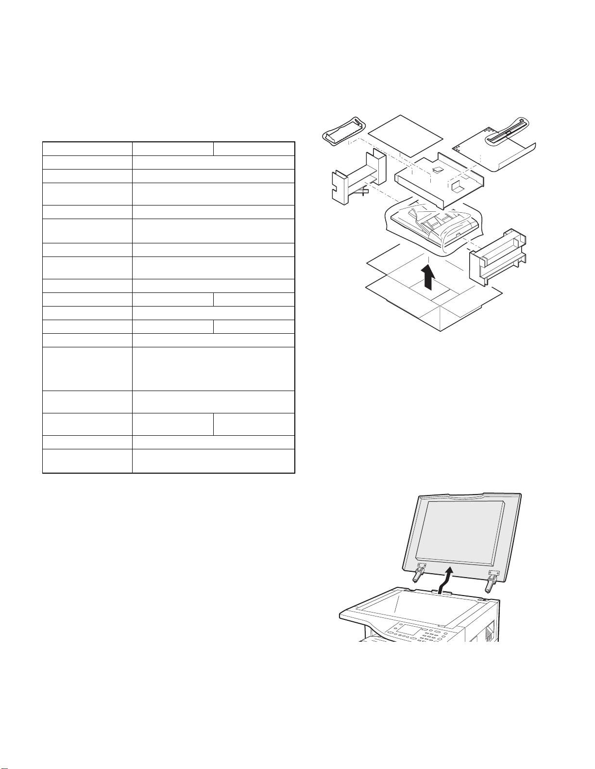
1. Unpacking
For unpacking, refer to the figure below.
2. Installation
Turn the main switch of the copier to the “OFF” position and then
remove the power plug of the copier from the outlet.
1. Remove the document cover.
Lift the document cover from the copier and tilt it to the rear side to
remove it.
AR-SP6N/RP6N PRODUCT OUTLINE
– 1 –
Page 4
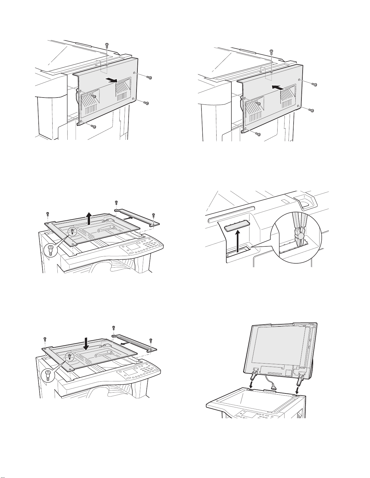
2. Remove the right cabinet.
Remove the screws and open the side door, and remove the rig ht cabi net.
5. Attach the right cabinet.
Reattach the right cabinet to its original position and fix it with the
screws.
3. Remove the document glass and the right document
glass holder.
Remove the screws, remove the document glass from the copier, and
then remove the right document glass holder.
4. Attach t he SPF glass holder.
Fit the SPF glass holder to the document glass.
Attach the document glass to the copier and fix it with the screws.
6. Cut out the cut-out portion.
Cut out the cut-out portion of the rear cabinet with nippers or the like.
At this time, be careful about the orientation of the nippers so that the
cut plane of the rear cabinet is flat.
7. Attach the automatic document feeder.
Insert the hinge portions of the document feeder into the mounting portions of the copier by holding the feeder at an angle toward the rear
side.
AR-SP6N/RP6N UNPACKING AND INSTALLATION
– 2 –
Page 5
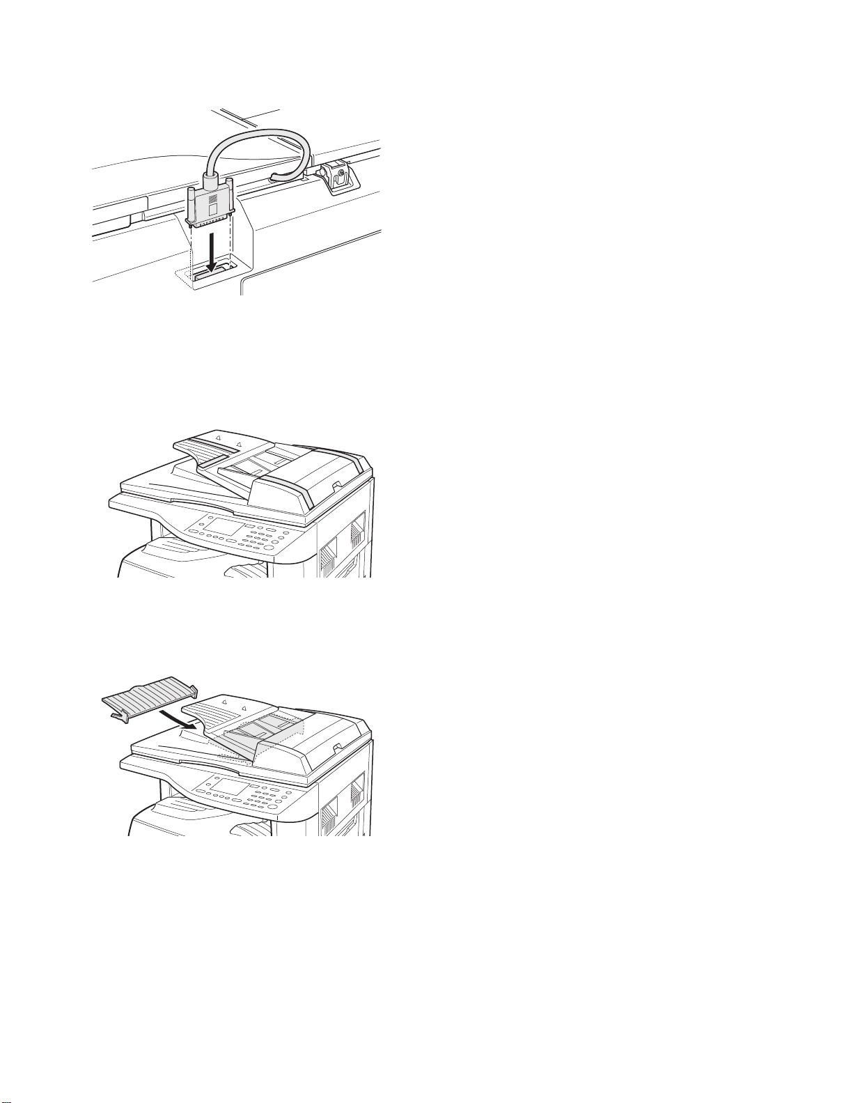
8. Connect the relay connector.
Connect the harness of the automatic document feeder to the connector of the copier and tighten the screws on the connector.
9. Remove the filament tape.
Remove the filament tape located in the positions shown in the illustration.
Insert the power plug of the copier to the outlet and turn on the main switch of the copier.
11. Check the SPF scanning position switching setting.
• Execute simulation 53-10 (SPF scanning position sw itching setting)
and check that the setting value is [1]. (If the value is [0], change it to
[1].)
12. Adjust the white compensation pixels.
• Open the automatic document feeder, execute simulation 63-7 referring to the service manual, and adjust the automatic white compensation pixels of the document feeder.
13. Check the copy magnification ratio.
• Set an original on the document glass and copy it.
Then, set an original in the document feeder tray and copy it.
• If the magnification rat io of the copy f rom the document feeder is different from that of the copy from the document glass, execute simulation 48-5 to carry out adjustment referring to the service manual.
14. Check the center displacement.
• Set an original on the document glass and copy it.
Then, set an original in the document feeder tray and copy it.
• If the center of the copy imag e from the document feeder is different
from that of the copy image from the document glass, execute simulation 50-12 to carry out adjustment referring to the service manual.
15. Check the top end position.
• Set an original on the document glass and copy it.
Then, set an original in the document feeder tray and copy it.
• If the top end position of the copy image from the document feeder is
different from that of the copy image from the document glass, execute simulation 50-06 to carry out adjustment referring to the service
manual.
10. Attach the intermediate tray. (AR-RP6N only)
Insert the intermediate tray all the way into the document feeder.
AR-SP6N/RP6N UNPACKING AND INSTALLATION
– 3 –
Page 6

Page 7
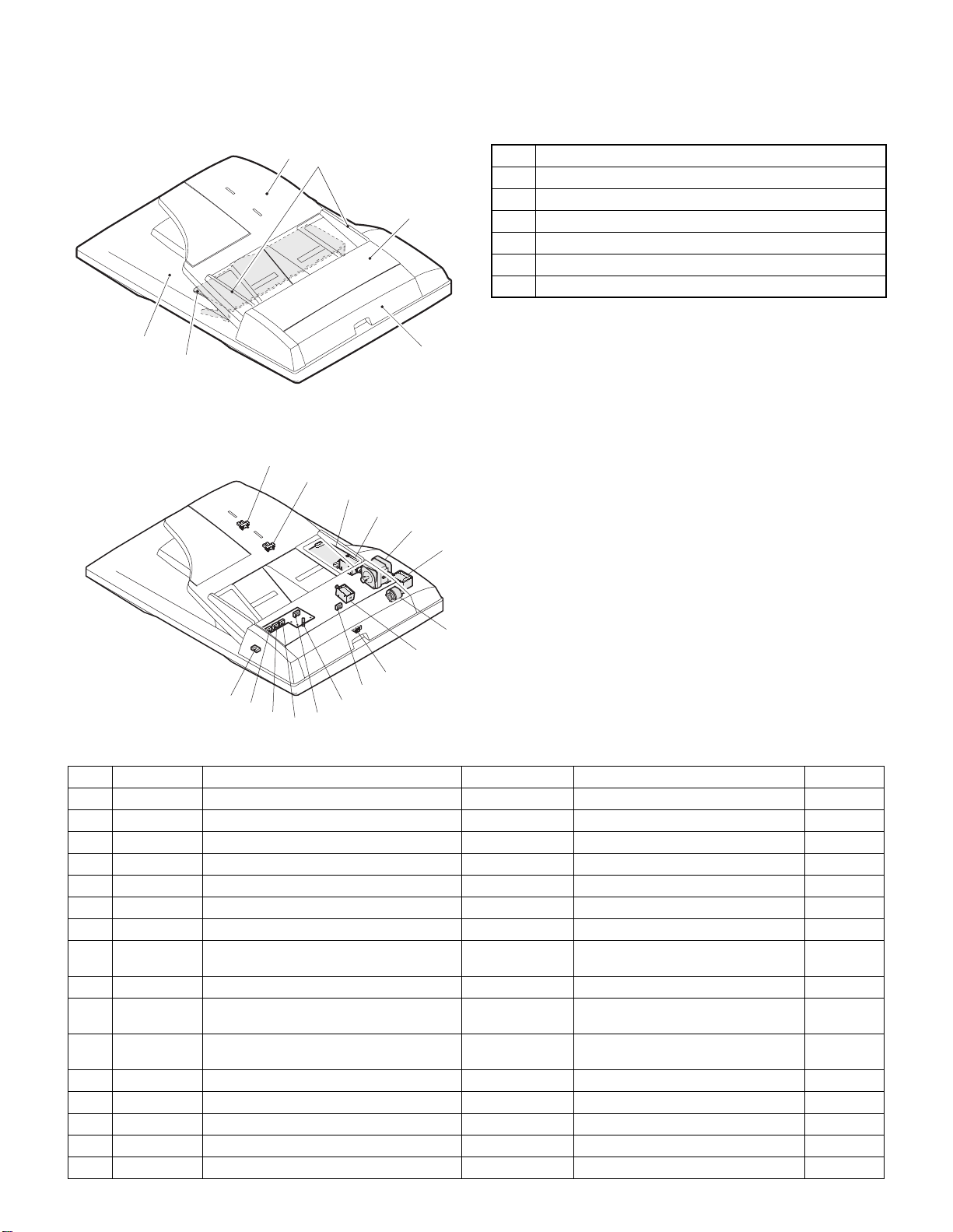
[4] EXTERNAL VIEW AND INTERNAL STRUCTURE
1. External view
5
6
2. Internal structure
14
1
2
3
No. Name
1 Document set tray
2 Document guide
3 Document feed section cover
4 Document transport section cover
5 Document exit section
6 Middle tray (AR-RP6N only)
4
13
12
11
10
8
9
6
7
15
5
4
3
16
2
1
Sensor, detector, etc.
No. Code Name Type Function/Operation Note
1 W0 Document set sensor Photo transmission Detects presence of documents.
2 COVER Open/close sensor Photo transmission Detects open/close of the paper feed unit.
3 W1 Document width sensor (A4R, LTR, A5, IV) Photo transmission Detects the document width on the tray.
4 W2 Document width sensor (B4, B5) Photo transmission Detects the document width on the tray.
5 W3 Document width sensor (WLTR, A3, A4, LT) Photo transmis sion Detects the document width on the tray.
6 PSOL Pickup solenoid — —
7 PAPER Paper entry sensor Photo transmission Detects presence of documents.
8 RSOL Pressure releas e solenoid — — AR-RP6N
9 CLH Transport clutch — —
10 MOT SPF (RSPF) motor Stepping motor Drives document feed on the tray, trans-
port, and paper exit roller.
11 GSOL Gate solenoid — — AR-RP6N
12 — Interface PWB — —
13 L1 Document length detection SW (Short) Photo transmission Detects the document length on the tray.
14 L2 Document length detection SW (Long) Photo transmission Detects the document length on the tray.
15 COVER OPEN Book sensor Photo transmission Detects the SPF (RSPF) float.
16 PO Paper exit sensor Photo transmission Detects presence of documents.
AR-SP6N/RP6N EXTERNAL VIEW AND INTERNAL STRUCTURE
– 4 –
only
only
Page 8

Page 9
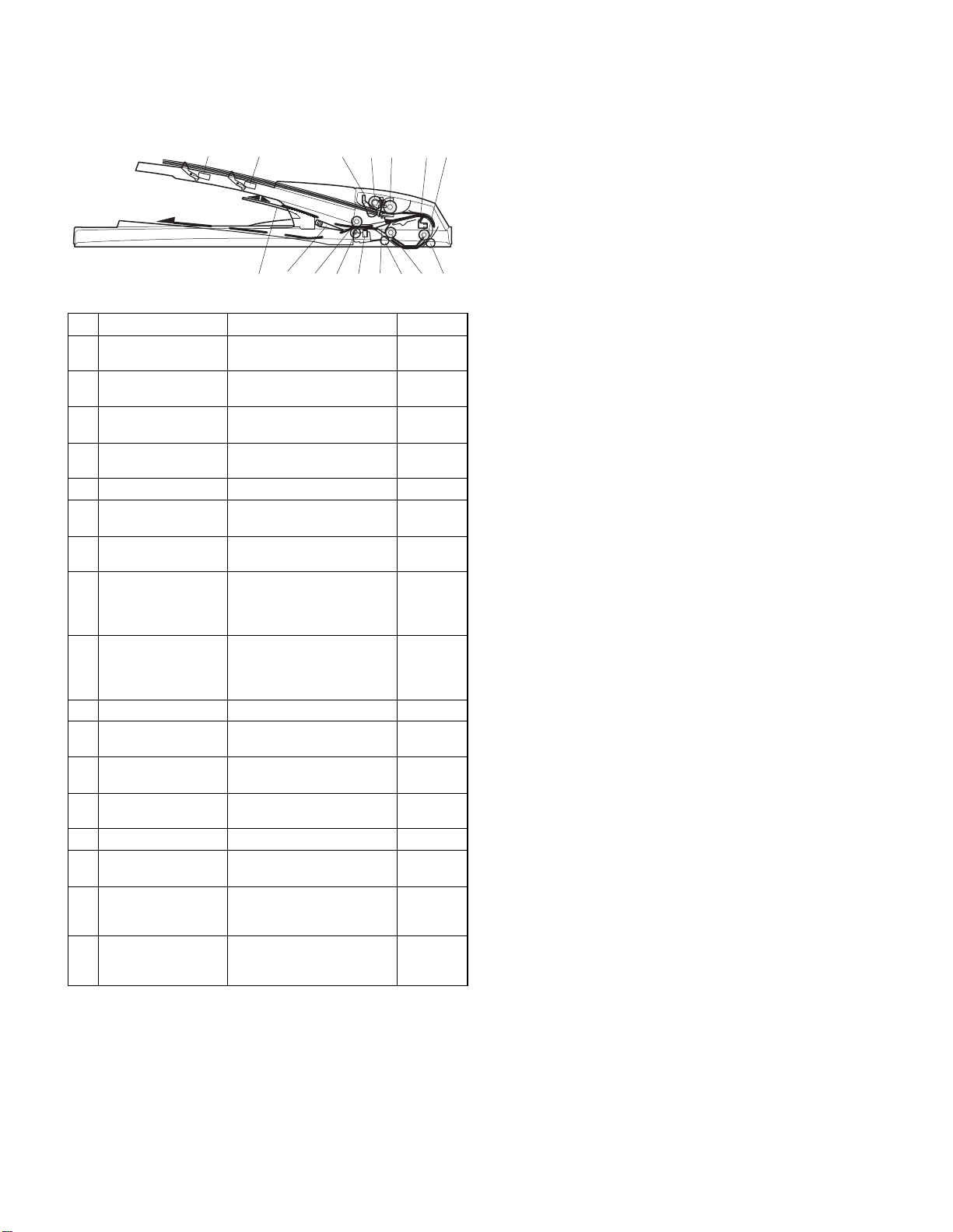
[5] OPEREATIONAL DESCRIPTIONS
1. Major parts of the paper feed section 2. Out line of operations
1 2 3,4 5 6 7 8
12
No. Part name Operation Note
1 Document length
sensor (L2)
2 Document length
sensor (L1)
3 Document set
sensor (W0)
4 Document width
sensor (W1, W2, W3)
5 Pickup roller Picks up documents.
6 Paper feed roller Feeds and transports docu-
7 Paper entry sensor
(PAPER)
8 PS roller Makes synchronization
9 PS follower roller Makes synchronization
10 Transport roller T ranspor ts documents.
11 Transport follower
roller
12 Paper exit sensor
(PO)
13 Paper exit follower
roller
14 Paper exit roller Discharges documents.
15 Reverse gate Opens/closes the document
16 Paper exit gate Separate document exit to
17 Intermediate tray Discharges documents to the
Detects the document length
on the tray.
Detects the document length
on the tray.
Detects presence of documents.
Detects the document width.
ments.
Detects transport of docu-
ments.
between the document lead
edge and the image lead
edge.
between the document lead
edge and the image lead
edge.
Transports documents.
Detects transport of documents.
Discharges documents.
reverse path.
the intermediate or the paper
exit tray.
intermediate tray during document reverse.
AR-RP6N
only
AR-RP6N
only
910111314 151617
Q AR-RP6N (RSPF)
[Duplex documents]
1) Document set (Document set sensor ON)
2) Document size detection (Document width sensors W1, W2, W3
3) Copier COPY key ON
4) RSPF motor ON
5) Pickup solenoid ON
6) Pickup roller and paper feed roller rotation
7) Paper entry sensor detects the document presence.
8) PS roller rotation
9) Copying (Front surface of document)
10) Transport roller rotation
11) Paper exit roller rotation
12) Paper exit gate falls down.
13) Reverse gate falls down.
14) Paper exit roller reverse rotation
15) Paper entry sensor detects document presence.
16) PS roller rotation
17) Copying (Back surface of document)
18) Transport roller rotation
19) Paper exit roller rotation
20) Paper exit gate falls down
21) Reverse gate falls down.
22) Paper exit roller reverse rotation
23) Paper entry sensor detects document presence.
24) PS roller rotation
25) Paper exit roller rotation
26) Paper exit gate lifts up.
27) Documents are fed to the paper exit tray.
28) Next document 3 (YES) 3 Go to 4).
29) RSPF motor OFF
4
detect the document width, and document length sensors L1, L2 detect the
4
4
4
4
4
4
4
4
4
4
(Documents are discharged to the intermediate tray.)
4
4
(Documents are fed to the reverse path.)
4
4
4
4
4
4
(Documents are discharged to the intermediate tray.)
4
4
(Documents are fed to the reverse path.)
4
4
4
4
4
4
(NO)
4
document length.)
AR-SP6N/RP6N OPEREATIONAL DESCRIPTIONS
– 5 –
Page 10
Q AR-SP6N (SPF)
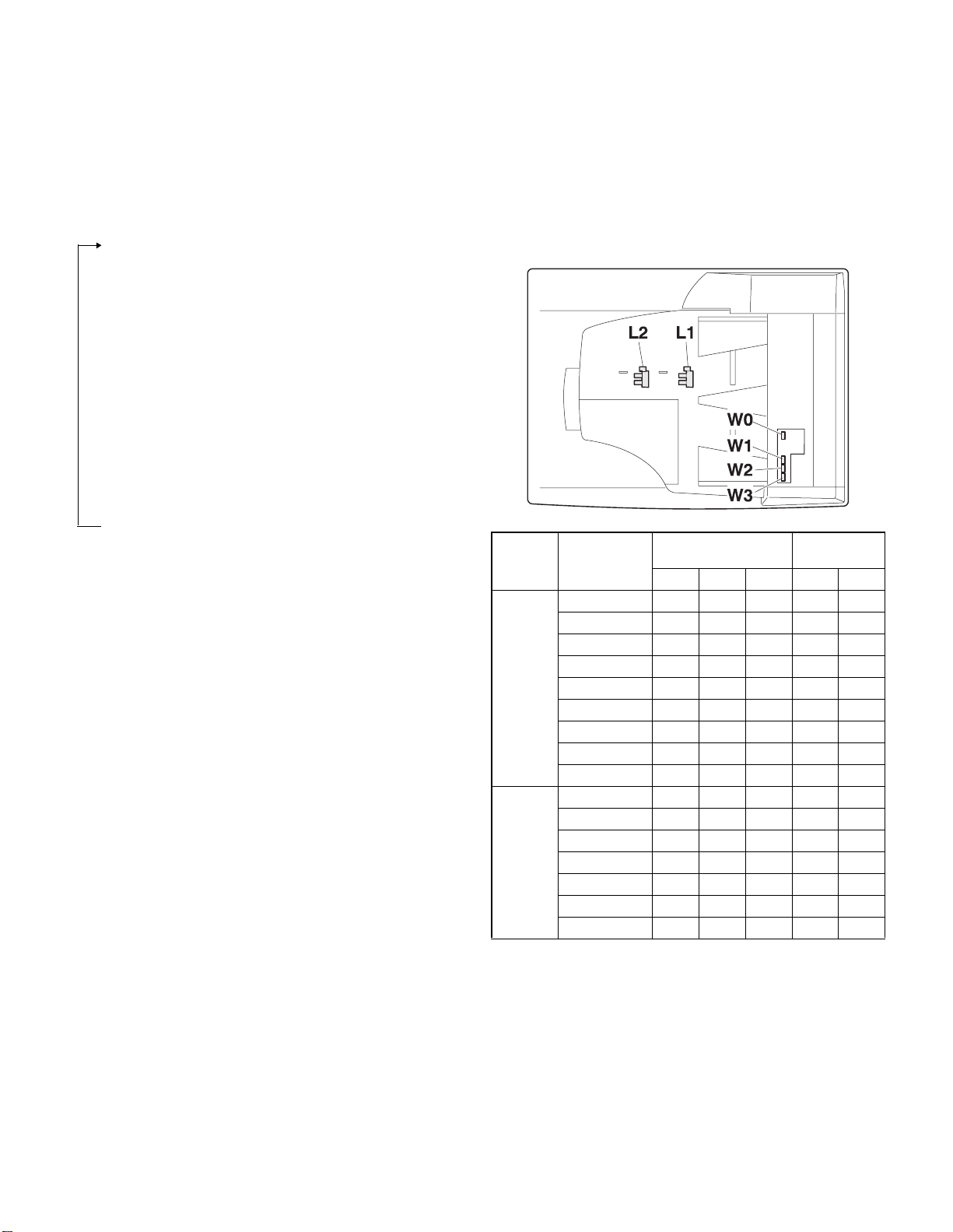
3. Document size detection
1) Document set (Document set sensor ON)
4
2) Document size detection (Document width sensors W1,
W2, W3 detect the document
width, and document length sensors L1, L2 detect the document
length.)
4
3) Copier COPY key ON
4
4) SPF motor ON
4
5) Pickup solenoid ON
4
6) Pickup roller and paper feed roller rotation
4
7) Paper entry sensor detects the document presence.
4
8) PS roller rotation
4
9) Copying (Front surface of document)
4
10) Transport roller rotation
4
11) Paper exit roller rotation
4
12) Documents are fed to the paper exit tray.
4
13) Next document 3 (YES) 3 Go to 4).
(NO)
14) SPF motor OFF
4
1) Document size detection with the document set tray
When documents are set on the document set tray in the auto selection
mode of paper/copy magnification ratio, the document size is detect ed
and paper and the copy magnification ratio are automatically selected.
When different sizes of documents are set, the max. size is detected.
The document width is detected by the document width sensors (W1,
W2, W3), and the document length is detected by the d ocument length
sensors (L1, L2) to identify the document size. Judgment of the document size is made in a certain timing af ter detecting the doc ument w ith
the document set sensor (W0).
Document
length sensor
AB series
Inch
series
Document set
size and set
direction
A5
B5
A5R
A4
B5R
A4R
8.5” x 13”
B4
A3
8.5” x 5.5”
8.5” x 5.5”R
11” x 8.5”
11” x 8.5”R
8.5” x 13”
8.5” x 14”
11” x 17”
Document width sensor
W1 W2 W3 L1 L2
onnnn
oonnn
nnnnn
ooonn
nnnon
onnon
onnoo
oonoo
ooooo
onnnn
nnnnn
ooonn
onnon
onnoo
onnoo
ooooo
Note: Detection sensor ON:
AR-SP6N/RP6N OPEREATIONAL DESCRIPTIONS
– 6 –
, OFF:
o
n
Page 11
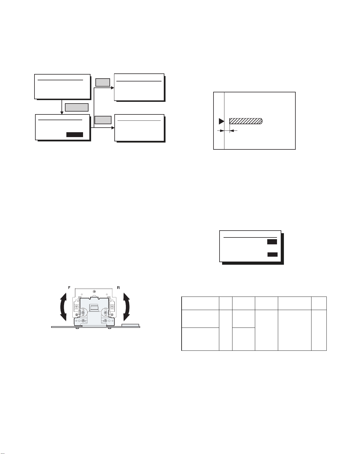
[6] ADJUSTMENTS
(1) Auto white correction pixel adjustment
1) Open the SPF fully.
2) Execute SIM63-7.
(
Initial window)
Sim63-7 SPF ADJ.
WHITE ADJUST
PRESS OK KEY EXEC
(Execution window)
Sim63-7 SPF ADJ
WHITE ADJUST
OK/START
EXEC
Failure
Success
3) When the process is completed, "COMPLETE" is displayed on the
LCD.
4) When "EROR" is displayed, perform the following procedures.
Q When the display is "- - -"
• Is the SPF closed?
• Is the lamp lighted? (If the lamp is not lighted, check the connector.)
• Is the CCD harness properly connected to the MCU connector?
Q When the display is 281 or above:
1) Remove the table glass.
2) Remove the dark box.
3) Sli de the lens uni t to the front side and insta ll it. Execute the simulation .
Q When the display is 143 or below:
1) Remove the table glass.
2) Remove the dark box.
3) Sli de t he lens un it t o the rea r side and inst all i t. Execut e the simulat ion.
Sim63-7 SPF ADJ.
WHITE ADJUST
ERROR
[---]
PRESS OK KEY EXEC
Sim63-7 SPF ADJ
WHITE ADJUST
COMPLETE
[160]
PRESS OK KEY EXEC
(2) Magnification ratio adjustment
Note: • When performing this adjustment, check that the CCD unit is
1) Place a scale on the OC table as shown below, and make a
2) Set the test chart to the SPF (RSPF) and make a normal copy.
3) Compare the copy and the test chart.
4) Execute SIM 48-5.
5) After completion of warming up, shading is performed.
6) Check to confirm that "RSPF(SIDE1)" mode is selected with the
7) Enter the set value, and press the START key.
<Adjustment specifications>
properly installed.
• When performing this adjustment, check that the OC mode
adjustment in copying is completed.
normal copy to make a test chart.
Note: Since the printed paper is used as the test chart,
place the scale in parallel to both sides.
If an adjustment is needed, perform the following procedures.
cross cursor.
Sim48-5 (R)SPF ZOOM
1:RSPF(SIDE1)
2:RSPF(SIDE2)
[ 1- 99]
50
50
50
The entered correction value is stored and a copy is made.
When the lens unit is moved, execute the OC main scanning direction
*
magnification ratio adjustment SIM48-1 and SIM48-3, and execute
the SPF document off-center adjustment.
This adjustment is basically completed with SIM63-7.
*
AR-SP6N/RP6N ADJUSTMENTS
Adjustment
mode
Sub scanning
direction ratio
(Front)
Sub scanning
direction
magnification rat i o
(Front)
– 7 –
SIM Disp0lay
text array
48-5 RSPF
(SIDE1)
RSPF
(SIDE2)
Set value Specifications Set
range
3
Normal
1.0% 1 ~ 99
m
+1
+0.1%
-1 3
-0.1%
Page 12
(3) Document off center adjustment
Note: When performing this adjustment, check that the paper off-cen-
ter is properly adjusted.
1) Set the center position adjustment test chart (made by yours elf) on
the SPF (RSPF).
<Adjustment specifications>
Draw a line in the center of paper. (In the scanning direction)
2) Make a normal copy from the manual feed tray, and compare the
copy and the test chart.
If an adjustment is required, perform the following procedures.
3) Execute SIM 50-12.
4) The current off-center adjustment value is displayed on the display
section in two digits.
5) Enter the set value and press the START key.
The entered correction value is started and a copy is made.
<Adjustment specifications>
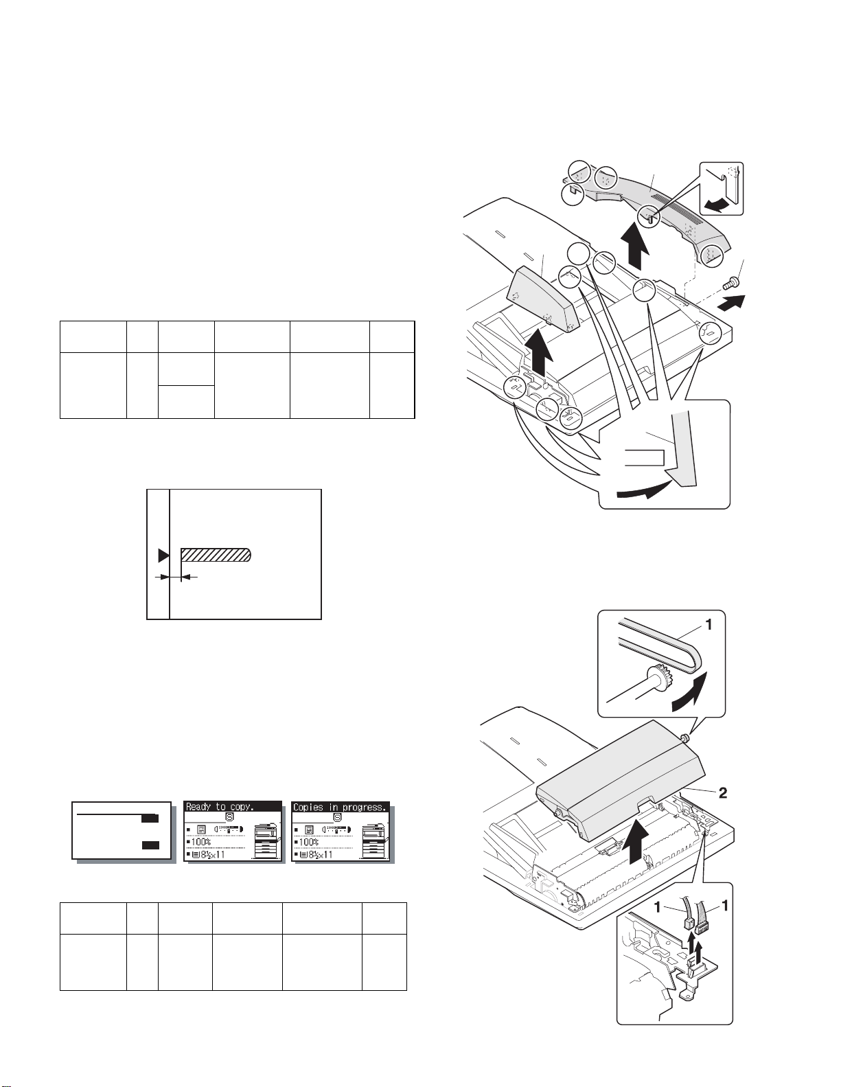
[7] DISASSEMBLY AND ASSEMBLY
1. External fitting section
Note: Turn the paw in the arrow direction.
2
3
1
Adjustment
mode
Document
off-center
SIM Disp0lay
text array
50-12 RSPF
(SIDE1)
RSPF
(SIDE2)
Set value Specifications Set
+1 3 +0.1mm
Slide to R side
-1
-0.1mm
3
Slide to L side
Center m 2.0% 1 ~ 99
range
(4) Image lead edge po sition a djustment
1) Set a scale on the OC table as shown below.
Note: Since the printed paper is used as the test chart,
place the scale in parallel to both sides.
2) Make a copy, and use the copied paper as the document and make
a copy from SPF (RSPF) again.
3) Check the copied paper. If an adjustment is re quired, perform the
following procedures.
4) Execute SIM 50-6.
5) Set the SPF/RSPF lead edge position set value so that the image
similar to the adjusted image at the OC image lead edge position
described previously is printed.
(Mode selection window)
Sim50-6 SPF EDGE
1:SIDE1
2:SIDE2
3:END EDGE
[ 1- 99]
50
50
50
50
(Copy start window) (Execution window)
2
2. Paper feed unit section
1) Paper feed unit
<Adjustment specifications>
Adjustment
mode
SPF image
lead edge
position
Refer to the AR-SP6/RP6 Service Manual about the adjustment
*
procedure required when attaching AR-SP6N to AR-M205/M160.
SIM Disp0lay
text array
50-6 SIDE1 1 step:
Set value Specifications Set
0.1mm shift
Lead edge void:
1 - 4mm
Image loss:
3mm or less
AR-SP6N/RP6 N DISASSEMBLY AND ASSEMBLY
range
1 - 99
– 8 –
Page 13

2) Document feed section cover
2
4) Pickup solenoid
Note: Remove section A of the pickup solenoid from the solenoid arm
groove.
When assembling, adjust the spacing between t he clutch latch
and sleeve with the pick-up solenoid pulled. The size should be
the distance from the tip of the clutch latch and the root of the
clutch sleeve latch.
3) Sensor PWB
2
1
2
1
1
A
1
3
4
2.5 4.5mm
5) Clutch gear ass’y
6
2
AR-SP6N/RP6 N DISASSEMBLY AND ASSEMBLY
– 9 –
6
5
1
2
3
4
From Edge pawl
2.5~4.0
Page 14

6) Pickup roller ass’y
Note: When assembling the pickup roller ass’y 4, check that rib A is on
the rib of the solenoid arm.
3. Interface PWB
1
1
A
2
A
1
B
2
4
1
B
A
3
4. Gate solenoid
7) Pick up roller, paper feed roller
4
3
1
Q AR-RP6N only
1
Bearing
1
1
2
Note: When assembling, check that the paper exit gate hook is set in
the solenoid groove.
When assembling, the bearing D-cut surface should be faced
down.
AR-SP6N/RP6 N DISASSEMBLY AND ASSEMBLY
– 10 –
Page 15

5. Document tray section
3) Document length sensor SW
1) Document tray
2
1
2) Rack cover
Q AR-RP6N
1
2
1
2
1
3
1
1
1
6. Drive frame section
Q AR-SP6N
1) Book sensor
2
2
1
3
1
1
1
2
AR-SP6N/RP6 N DISASSEMBLY AND ASSEMBLY
– 11 –
Page 16

2) Drive frame unit
1
4) Pressure release solenoid
Q AR-RP6N only
Note: Make sure the spring pin A is inserted into the slot.
Make sure that the clearance between the position at which force
is applied and the sound deadening sponge is 0.5 ~ 2 mm when
the pressure release solenoid plunger is pulled toward the solenoid side.
2
1
3) Drive frame ass’y and drive belt
1
0.5 3mm
1
A
3
1
2
5) RSPF motor / SPF motor
1
1
2
4
3
3
4
2
AR-SP6N/RP6 N DISASSEMBLY AND ASSEMBLY
– 12 –
Page 17

7. Transport section
1) Clutch
Note: When assembling, check that the rib is in the clutch groove A
and fix it with E-ring.
2
A
4) Transport roller
Note: Note that the spring will come off when removing.
Q AR-RP6N
1
1
2) Transport roller gear
1
1
1
3) Reverse gate
Q AR-RP6N only
Note: When assembling the inversion gate, apply grease G-484 on the
area A.
3
A
1
1
1
Q AR-SP6N
1
1
A
A
2
1
AR-SP6N/RP6 N DISASSEMBLY AND ASSEMBLY
– 13 –
Page 18

5) PS roller
7) Paper feed paper guide upper
2
1
1
1
2
1
1
6) Paper feed paper guide lower
Note: When assembling, check that the paper feed paper guide lower
is securely set to rib A and boss B.
+
1mm
-
0 0.5mm
2
1
8) Paper exit roller
1
1
2
8. Hinge L
B
A
Note: When assembling the hinge L, reference is based on the mark of
1
AR-SP6N/RP6 N DISASSEMBLY AND ASSEMBLY
– 14 –
base tray and the center line of the 5 lines of the hinge L
extended horizontally.
1
1
2
1
Page 19

[8] MAINTENANCE
1. Maintenance parts
No. Name Work item S ervice call Remark
1 Pickup roller Cleaning
2-1 Sepa ration unit Cleaning
2-2 Front separation
sheet
3 Paper feed roller Cleaning
4 PS roller Cleaning
5 Transport roller Cleaning
6 Paper exit roller Cleaning
Cleaning
o
Replace when
o
worn down.
o
o
o
o
o
1
Q How to use the glass cleaner
In case black lines appear on copies when copying with the automatic
document feeder...
1. Open the automatic document feeder and take the glass cleaner
out.
2. Clean the scanning section with the glass cleaner.
2-2
3
3. put the glass cleaner back into the original place.
2-1
6
5
4
Note: When performing maintenance, refer to [7] DISASSEMBLY AND
ASSEMBLY.
AR-SP6N/RP6N MAINTENANCE
– 15 –
Page 20

Page 21

D
1
SENSOR
5V
C
B
SOL/CLU
A
RSPF ONLY
5V
5V
24V
24V
5V
24V
24V
24V
24V
24V
234
L2
L1
W0W1W2
SPF SENSOR PWB
W3
PAPER
/SPFOUT
SPFOPEN
/CLH
/PSOL
/RSOL
/GSOL
MOTOR
(A,B,/A,/B)
2 1
/SPFCOVER
3
5
DATA
SELECTOR
5V
TRANSISTOR
24V
ARRAY
MOTOR
DRIVER
5 4
SPF/RSPF INTERFACE PWB
678
7 6
[9] ELECTRICAL SECTION
1. Block diagram
YSPF
(MCU PWB)
D
SEL(A#,B#,C#)
/SPFCOVER
C
AR-SP6N/RP6N ELECTRICAL SECTION
PAPER
– 16 –
/SPFOUT
SPFOPEN
SPF(CLH,PSOL,RSOL,GSOL)
B
/MODA,/MODB)
SPF(MODA,MODB,
A
PDOWNA
PDOWNB
8
Page 22

D
C
B
A
12345678
DSPF ONLY
ORIGINAL TRAY
Sensor PWB
PAPER FEED UNIT
W0
5v
1
2
BL
PLBRLB
OR
SPFCOVER
W3
W2
W1
3
SGND7
6
5
4
GY
PK
SPFPSOL
L1
321
ORLBGY
L2
321
ORGYBL
PAPER
(Paper Entry Sensor)
213
GYBRPL
SPFRSOL
SPFGSOL
A
3
1
BLLBPK
/B2/A
PLUSE MOTOR
4B
PLRDRD
24V1624V1
5
2 1
PHR-7
BLORPLBRLBGYPK
2
3
5V
W1
W0 17
BU7P-TR-P-H
6
5
BLORPLBRLBGYPK
PHDR-20
BLORPLBRLBGYPK
7
1
5
5VW0W1
CN6
B20B-PHDSS
PHR-3
DF3-3S-2C
ORLBGY
PHNR-7-HPHNR-7-H
SGND 71
SPFCOVER 62
W3 53
W2 44
1
2
SPFPSOL
24V1
BU2P-TR-P-H
2
1
BL
RD
PHNR-2-H
BU6P-TR-P-H
2
L1
5V 16
5
ORLBGY
3
SGND
4
ORGYBL
5V 43
ORGYBL
PHNR-2-H
BL
RD
9
20314
SGND
W2
W3
SPFCOVER
11
/PSOL 6
24V1
ORLBGY
2
15
L1
5V
16
SGND
ORGYBL
45V
DF3-3S-2C
PHNR-6-HPHNR-6-H
SGND 61
L2 52
1
SPFRSOL
1
LB
2
SMR-02V-N(JST)
24V1
2
RD
SMP-02V-BC(JST)
GYBRPL
17SGND
L2 13
18SGND
pull up 8
LB
19PAPER
PHR-2
RD
24V1 1
CN4
B2B-PH-K-S
2/GSOL
1224V1
/RSOL 10
PHR-6
PHR-7
BLLBPK
1A
CN3
B7B-PH-K-S
3
PL
RD
RD
3/B
2/A
5N.C.
4B
724V1
624V1
2. Actual wiring diagram
PAPER
1
CN5
B26B-PHDSS
25
PAPER
MCU PWB Interface PWB
/SPFCOVER
SELA#
3
2
20
16
/SPFCOVER
SELA#
D
SPFMODB
SELB#
5
4
17
SPFMODB
SELB#
/SPFMODB
SELC#
3 7 6
/SPFMODB
SELC#
N.C.6SGND
SGND7YSPF
9108
12
13-18
N.C.
SGND
SGND
11
15
YSPF
SPFOPEN
5V
12
13
24
SPFOPEN
5V
SPFMODA
SPFGSOL
15
16
22
5
SPFGSOL
SPFMODA
/SPFMODA
SPFRSOL
181719
4 921
/SPFMODA
SPFRSOL
SPFCLH
SPFCLH
PDOWNA
PDOWNA
SPFPSOL
212220
1023 8
SPFPSOL
/SPFOUT
14
19
/SPFOUT
C
AR-SP6N/RP6N ELECTRICAL SECTION
– 17 –
PDOWNB
PDOWNB
PGND
23
11
PGND
PGND
24
14
PGND
SPF0PEN2
SGND
N.C.2
24V1
24V
24V
25
26
CN7
1
B3B-PH-K-S
/CLH
3
CN1
BL
FG
PHR-3
SRA-21T-4
SRA-21T-4SRA-21T-4
BL BL
BL
1
2
26
FG
24V
24V
SPFCLH
5V
3
1
B3B-PH-K-R(RD)
GY
OR
BRBR
PHR-3(RD)
DF3-3S-2C
GY
OR
123
/SPFOUT2
SGND
1
CN2
B3B-PH-K-K(BK)
GY
GR
PHR-3(BK)
DF3-3S-2C
GYORGR
123
5V
3
OR
EARTH PLATE(SPF ONLY)
8 7 6 5 4
SPFOPEN
(Book Sensor)
B
/SPFOUT
(Paper Exit Sensor)
A
Page 23

D
CN2-6 (B3)
CN6-3 (B2)
CN2-10 (B3)
CN3-3 (A2)
C
B
A
12345678
/CLH
/RSOL
/GSOL
/PSOL
24V1
C115
0.047u/50V
C114
0.047u/50V
5V
IC2
1C2C3C4C5C6C7C
1B2B3B4B5B6B7B
SPFCLH
SPFPSOL
(A4) CN1-21
(A4) CN1-19
IC101
COM
GND
TD62003AP
SPFRSOL
SPFGSOL
(A4) CN1-17
(A4) CN1-15
CN1-11 (A4)
YSPF
ZD102
UDZ5.6
C120
0.1u/25V
Y
W
VCC
D0D1D2D3D4D5D6D7ABC
GND
CN7-4 (B2)
CN7-3 (A2)
CN7-2 (B3)
CN7-1 (B3)
CN7-6,7 (B3)
BA/B
/A
2 1
Pattern width: 0.5mm or above
C1
47u/35V
3
C104
C107
R107
R101
0.047u/50V
24V1
7.5KJ
C113
7.5KJ
2200pF/50V
2200pF/
50V
C110
C103
3300pF/50V
0.047u/50V
IC1
R104
C108
0.1uF/25V
1KJ
Vmm
CrA
CrB
R102 2.4k
OUT A
VsA
R1 1.5(1W)
OUT B
RsA
NCNCNCNCNCNCPG
OUT /A
OUT /B
VrefA
VrefB
RsB
VsB
R2 1.5(1W)
R106 2.4k
LG
PG
PG
In /A
In A
In /B
R105
1KJ
C112
In B
0.1uF/25V
C111
MTD1361
3300pF/50V
/SPFMODB
/SPFMODA
SPFMODA
(C4) CN1-6
(C4) CN1-16
(C4) CN1-18
Pattern width: 1.0mm or above
SPFMODB
(C4) CN1-4
CN1-5 (A4)
CN1-7 (A4)
CN1-3 (A4)
SELA#
SELC#
SELB#
C118
1000p/50V
C117
1000p/50V
C119
1000p/50V
ZD103
UDZ5.6
ZD101
UDZ5.6
ZD104
UDZ5.6
G
74HC151
R111
R113
R112
R115
R114
R117
R116
10K
10K
10K
10K
10K
10K
10K
Document size senser
W0W2W3W1L2
(A3) CN2-9
(A3) CN2-3
(A3) CN2-7
L1
(A3) CN2-5
(A3) CN2-15
(A3) CN2-13
5V
3-1. Interface PWB (1/2)
3. Circuit Diagram
D
C122
C121
C124
C123
C126
C125
/SPFDTC
1000pF/50V*7
JP1
DSPF
Y
W3
W2
W1
W0
/SPFDTC (L)
L2
L1
SPF(H)/DSPF(L)
LHLHLHL
SELA
L
SELB
LLL
SELC
Sensor Matrix
L
H
L
L
H
H
H
H
L
H
HHH
C
AR-SP6N/RP6N ELECTRICAL SECTION
– 18 –
C2
5V
R103
620F
TP103
$PIN0
R109
430F
$PIN0
TP102
R108
390F
1
TP101
B
10u/16V
C109
0.1u/25V
110F
R110
10k
Q102
DTC114EK
10k
10k
Q101
DTC114EK
PDOWNA
(C4) CN1-20
10k
PDOWNB
(C4) CN1-22
8 7 6 5 4
$PIN0
A
Page 24

D
C
B
A
12345678
CN1-2 (C4)
(E4)
(D4)
/PSOL
/RSOL
8
1012141618
/SPFCOVER
20
R119
R118
470
470
246
5V
123
CN7
B3B-PH-K-S
24V1
/CLH
(E4)
2 1
1357911131517
CN6
5V
24V1
W3
W1W2W0
(B3)
(B3)
CN4-2 (B2)
(C1)
CN2-20 (B3)
(B2) CN5-2
(C1)
/SPFOUT
SPFMODB
SPFOPEN
/SPFMODB
/SPFCOVERPAPER
(B3)
(B3)
(C1)
(C1)
SPFMODA
PDOWNA
/SPFMODA
L2
L1
(B3)
(B1)
(B1)
PDOWNB
(B3)
19
PAPER
CN1-1 (A4)
24V1
F1
B20B-PHDSS
C127
0.1u/25V
ICP-N38
0.047u
C105
C106
0.047u
CN1-14 (C4)
C102
0.1u/25V
/SPFOUT
5V
123
CN2
B3B-PH-K-E(BL)
CN1-12 (C4)
C101
0.1u/25V
SPFOPEN
5V
123
CN1
B3B-PH-K-R(RD)
3
246
CN5
135791113151719212325
SELA#
CN2-19 (A3)
3-2. Interface PWB (2/2)
D
8
101214161820222426
SELB#
SELC#
YSPF
(E3)
(E3)
(E3)
(E3)
SPFGSOL
5V
5V
(D4)
SPFPSOL
SFPRSOL
SPFCLH
(D4)
(D4)
B26B-PHDSS
C116
0.1u/25V
+
C3
10u/16V
(D4)
C
AR-SP6N/RP6N ELECTRICAL SECTION
– 19 –
1
2
CN4
B2B-PH-K-S
24V1
/GSOL
(E4)
CN3
24V1
1234567
B7B-PH-K-S
A/A/B
B
(E4)
(E4)
(E4)
(E4)
8 7 6 5 4
B
A
Page 25

D
C
B
A
12345678
2 1
3
3-3. Sensor PWB
D
C
AR-SP6N/RP6N ELECTRICAL SECTION
– 20 –
8 7 6 5 4
B
A
Page 26

Page 27

4. Parts arrangement
4-1. Interface PWB
a. Parts surface
CN3(B7B-PH-K-S)
1
2
3
4
5
6
7
CN4(B2B-PH-K-S)
1
2
CN6(B20B-PHDSS)
25V15V
45V3W3
6 /PSOL 5 W0
8 Pull up 7 W1
10 /RSOL 9 W2
12 24V1 11 24V1
14 SGND 13 L2
16 SGND 15 L1
18 SGND 17 SGND
20 SPFCOVER 19 PAPER
A
/A
/B
B
N.C.
24V1
24V1
24V1
/GSOL
CN7(B3B-PH-K-S)
1 24V1
2 N.C.
3/CLH
CN1(B3B-PH-K-R RD)
1 SGND
2 SPFOPEN
35V
CN2(B3B-PH-K-E BK)
1 SGND
2 /SPFOUT
35V
CN5(B26B-PHDSS)
24V1
25
PGND
23
SPFPSOL
21
SPFCLH
19
SPFRSOL
17
SPFGSOL
15
13
11
5V
YSPF
SGND
9
SELC#
7
SELB#
5
SELA#
3
PAPER
1
26
24
PDOWNB
22
PDOWNA
20
/SPFMODA
18
SPFMODA
16
/SPFOUT
14
SPFOPEN
12
SGND
10
8
/SPFMODB
6
SPFMODB
4
/SPFCOVER
2
24V1
PGND
N.C.
b. Solder surface
4-2. Sensor PWB
AR-SP6N/RP6N ELECTRICAL SECTION
– 21 –
Page 28

Page 29

q
PARTS GUIDE
CODE:00ZARRP6N/P1/
デジタル複合機オプション
デジタル複合機オプション
デジタル複合機オプションデジタル複合機オプション
原稿自動送り装置(
原稿自動送り装置(SPF
原稿自動送り装置(原稿自動送り装置(
両面原稿自動送り装置(
両面原稿自動送り装置(RSPF
両面原稿自動送り装置(両面原稿自動送り装置(
Digital Copier
Single Pass Feeder (SPF)
Reverse Pass Feeder (RSPF)
SPF))))
SPFSPF
RSPF))))
RSPFRSPF
MODEL
このパーツガイドに掲載されている表示価格ランクは消費税抜きです。
CONTENTS
1
外装部 (Exteriors)
2
給紙部 (Paper feed unit)
3
搬送部 (Transport unit)
4
梱包及び付属品 (Packing material & Accessories)
■
索引 (Index)
AR-SP6N
AR-RP6N
本書はサービス活動用に作成した資料です。
一部内容が製品の改良・改善等により予告
なしに変わることがあります。
SHARP CORPORATION
This document has been published to be used for
after sales service only.
The contents are subject to change without notice.
Page 30

補修部品のランク付
市場における補修部品の在庫管理が、適正に運営出来る手助けとなることを、目的とします。
Aランク : メンテナンスパーツ、メンテナンスパーツには入っていないがメンテナンスパーツに近い消耗パーツ。
Bランク : 性能・機能パーツ(センサー、クラッチ等の電気パーツ)、消耗パーツ。
Eランク : 基板含むユニットパーツ。
Dランク : 整備パーツ(外装、パッキング、同梱パーツ)。
Cランク : 上記ランク以外のパーツ(基板の子部品を除いたもの)。
DEFINITION
Rank A : Maintenance parts, and consumable parts which are not included in but closely related to maintenance parts
Rank B : Performance/function parts (sensors, clutches, and other electrical parts), consumable parts
Rank E : Unit parts including PWB
Rank D : Preparation parts (External fitting, packing, parts packed together)
Rank C : Parts other than the above (excluding sub components of PWB)
安全性・信頼性確保のため部品は、必ず正規のものをご使用下さい。
!
印の商品は、安全上重要な部品です。交換をする時は、安全及び性能維持のため必ず指定の部品をご使用下さい。
Because parts marked with "!" is indispensable for the machine safety maintenance and operation, it must be replaced with
the parts specific to the product specification.
F
当モデルのサービス資料には、この資料以外にサービスマニュアル ( 回路図含む ) があります。合わせてご利用下さい。
F Other than this Parts Guide, please refer to documents Service Manual(including Circuit Diagram)of this model.
F Please use the 13 digit code described in the right hand corner of front cover of the document, when you place an order.
F For U.S. only-Use order codes provided in advertising literature. Do not order from parts department.
1
外装部 (Exteriors)
NO. PARTS CODE
1 LSOU-0015QSE3 AX FG D
2 LSOU-0017QSE2 AP EQ D
3 LPLTP0107QSE1 AH DX C
4 LPLTP0108QSE1 AH DX C
5 NGERR0377FCZZ AD DJ C
6 XEPSD30P08X00 AA DD C
7 NGERH0193FCZZ AB DD C
8 MSPRP0059QSZZ AD DJ C
9 MLEVP0035QSE1 AC DJ C
10 VHPGP1A71A1-1 AG DX B
11 DHAI-0070QSZ1 AG DS C
12 PCOVP0039QSE2 AQ EQ D
13 LSOU-0016QSEZ AP EQ D
14 CFRM-0029RS59 BK HC N E
15 GCAB-0051QSZA AT EZ D
16 GCAB-0022QSE2 AK DX D
19 MHNG-0013QSPZ BA FX N C
20 XEBSE40P12000 AA DD C
21 LSOU-0028QSZC BF GN D
22 PCUSS0022QSZZ AW FG C
23 PSHEZ0077QSZ1 AE DJ C
24 XEBSE30P08000 AA DD C
25 PSHEZ0078QSZZ AF DS C
26 NROLP0011QSZZ AD DJ C
27 PGUMR0315FCZZ AC DJ N C
28 NSFTZ0013QSPZ AL EB N C
29 NBRGM0501FCZZ AB DJ C
30 PSHEZ0284QSZZ AB DJ C
31 LPLTM0110QSEZ AF DS C
32 XHBSD30P10000 AA DD C
33 MSPRD0267QSZ1 AC DJ C
34 MSPRD0268QSZ1 AC DJ C
NSFTZ0030QSPZ AP EQ N C
35
NSFTZ0035QSP1 AP EQ N C
36 NROLP0091GCAZ AE DS C
37 NSFTZ0009QSPZ AL EB N C
38 MSPRP0123QSZZ AD DJ C
39 MSPRP0060QSZZ AD DJ C
40 LPLTM0109QSZ1 AG DS C
41 MHNG-0014QSPZ BA FX N C
42 PSHEZ0268QSZZ AC DD C
43 PSHEZ0069QSZZ AE DJ C
MLEVF0040QSZZ AD DJ C
44
MLEVF0041QSZZ AD DJ C
45 LPLTM0111QSZZ AC DJ C
46 DHAI-0446QSZZ BA FG C
CPWBF0084QSE3 BA FX E
47
CPWBF0084QSE4 BA FX E
PRICE RANK
Ex. Ja.
NEW
MARK
PART
RANK
Original tray 原稿トレイ
Original tray S 原稿トレイ S
Regulation plate F 規制板 F
Regulation plate R 規制板 R
Manual feed rack 手差しラック
Screw(3×8) ビス
UC manual feed gear UC 手差しギヤ
Regulation plate spring 規制板スプリング
Original detect actuator 原稿検知アクチュエーター
Photo sensor(GP1A71A1) フォトセンサー
Original tray harness 原稿トレイハーネス
Rack cover ラックカバー
Middle tray [AR-RP6N] 中間トレイ
Paper feeding unit 給紙ユニット SPF
Rear cabinet 後キャビネット
Front cabinet 前キャビネット
SPF hinge L SPF ヒンジ L
Screw(4×12) ビス
Base tray R ベーストレイ R
OC mat OC マット
OC mat sheet F OC マットマイラー F
Screw(3×8) ビス
OC mat sheet R OC マットマイラー R
Paper exit roller 排紙従動ローラー
Rubber 蹴出しゴム
Paper exit roller shaft 排紙従動軸
Bearing(B-F6-7) 軸受
Pressure release lever silence sheet [AR-RP6N] 圧解レバー消音シート
Release plate 圧力解除板
Screw(3×10) ビス
Paper exit spring F 排紙従動スプリング F
Paper exit spring R 排紙従動スプリング R
Pressure release shaft [AR-SP6N] 圧力解除軸
Pressure release shaft [AR-RP6N] 圧力解除軸
Transport roller 搬送従動ローラー
Transport shaft 搬送従動軸
Transport spring 搬送従動スプリング
Transport spring 搬送従動スプリング
Base tray reinforce plate ベーストレイ補強板
SPF hinge R SPF ヒンジ R
PS support sheet PS 従動マイラー
Base tray sheet ベーストレイマイラー
Pressure release lever [AR-SP6N] 圧解レバー
Pressure release lever [AR-RP6N] 圧解レバー
Reinforce plate earth 補強板アース
SPF harness SPF ハーネス
SPF interface PWB [AR-SP6N] SPF 中継基板
RSPF interface PWB [AR-RP6N] RSPF 中継基板
DESCRIPTION
– 1 –
Page 31

1
1
外装部 (Exteriors)
NO. PARTS CODE
48 XWVSD40-05000 AA DD C
49 PSHEZ0285QSZZ AB DJ C
50 LX-BZ3008SCPM AA DD N C
51 PSPO-0023QSZZ AB DJ C
52 MSPRD0212QSZZ AD DJ C
53 MSPRD0154QSZZ AD DJ C
54 XRESP50-06000 AA DD C
55 XEBSE40P14000 AA DD C
56 RCORF0026FCZZ AL EB C
58 PSHEZ0215QSZZ AD DJ C
59 MSPRD0211QSZZ AC DJ C
60 MLEVP0073QSZ1 AD DJ C
61 DHAI-0248QSZ1 AE DJ C
62 NROLP0059GCZZ AC DJ C
63 LPLTP0117QSZZ AM EG C
64 MLEVP0036QSZZ AD DJ C
65 MSPRD0162QSZZ AC DJ C
66 PRNGP0090FCZZ AA DJ C
67 NBRGP0041GCZZ AD DJ C
68 RPLU-0011QSZ1 AQ EQ B
69 PSPO-0004QSZZ AB DJ C
70 XBBSD30P05000 AA DD C
71 MSPRP0150QSZZ AC DJ C
72 PSPO-0003QSZZ AC DJ C
73 XRESP20-04000 AA DD C
74 XHBSE30P08000 AA DD C
75 PSHEZ0438QSZZ AA DJ C
77 MSPRC0274QSZZ AC DJ C
78 DHAI-0154QSZ1 AC DJ C
79 TLABH0601QSZZ AG DX N D
80 TLABH0323QSZZ AD DJ D
81 CCLEZ0020QS01 AK EB D
82 PGUMR0316FCZZ AB DJ N C
83 PSHEZ0503QSZZ AC DJ N C
CSOU-0028RS60 BQ LP N E
501
CSOU-0028RS61 BR LX N E
CSOU-0015RS59 BE GN N E
502
CSOU-0015RS60 BF GN E
PRICE RANK
Ex. Ja.
NEW
MARK
PART
RANK
Washer ワッシャー
Delivery support silence sheet [AR-RP6N] 排紙従動消音シート
Screw(3×8) ビス
Damper cushion [AR-RP6N] 消音スポンジ
SPF earth spring PS 従動アーススプリング
Earth spring 排紙従動アーススプリング
E type ring E- リング
Screw(4×14) ビス
Core(TFC-16813) コア
Solenoid sheet 圧解ソレノイド放熱シート
Paper exit sensor ACT spring 排紙センサー ACT スプリング
Paper exit sensor ACT lever 排紙センサー ACT レバー
Paper exit sensor harness 排紙センサーハーネス
Transport roller 1 搬送従動ローラー 1
Paper exit gate [AR-RP6N] 排紙ゲート
Paper exit gate lever [AR-RP6N] 排紙ゲートレバー
Paper exit gate spring [AR-RP6N] 排紙ゲートスプリング
E type ring [AR-RP6N] E リング
Bearing [AR-RP6N] 軸受
Gate solenoid [AR-RP6N] ゲートソレノイド
Gate cushion [AR-RP6N] 排紙ゲート用スポンジ
Screw [AR-RP6N] ビス
Lock spring [AR-RP6N] 中間トレイロックスプリング
Gate cushion [AR-RP6N] 圧解消音スポンジ
E type ring E- リング
Screw(3×8) ビス
Sheet B マイラー B
Pressure release lever earth spring (Taiwan only) 圧解レバーアーススプリング
SPF ground wire [AR-SP6N] SPF グランド線
Cleaning cautions label (Japan only) 清掃注意ラベル
Scanner direction directions label スキャナ方向指示ラベル
SPF glass cleaner AS SPF ガラスクリーナー AS
Rubber 蹴出しゴム
OC mat auxiliary sheet OC マット補助マイラー
Base tray unit [AR-SP6N] ベーストレイユニット
Base tray unit [AR-RP6N] ベーストレイユニット
Original tray unit [AR-SP6N] 原稿トレイユニット
Original tray unit [AR-RP6N] 原稿トレイユニット
DESCRIPTION
外装部 (Exteriors)
13
3
502
71
24
83
2
9
10
9
10
6
12
6
24
83
22
1
6
48
81
23
24
6
7
8
71
24
48
20
63
72
82
26
73
4
80
79
5
16
20
55
11
21
19
25
28
49
27
54
29
48
66
49
31
34
33
50
14
20
74
56
67
24
27
62
45
47
43
42
75
82
35
38
53
75
73
26
54
37
38
36
24
24
15
24
20
32
46
58
70
68
64
69
65
44
42
75
61
10
59
60
48
29
48
20
62
36
62
39
52
37
39
24
24
24
20
51
30
24
77
41
40
501
50
78
24
PRP02401
– 2 –
Page 32

2
給紙部 (Paper feed unit)
NO. PARTS CODE
1 GCAB-0025QSE3 AN EG D
2 PSPO-0002QSZZ AC DJ C
4 MARMP0003QSZ1 AD DJ C
5 LSTPP0001QSZZ AD DJ C
6 XEBSE30P08000 AA DD C
7 CPWBF0017QSE2 AR EQ E
8 DHAI-0071QSZ1 AG DS C
9 MLEVP0090QSZ1 AC DJ C
10 MLEVP0010QSZZ AE DJ C
11 RPLU-0004QSZ2 AQ EQ B
12 XBPSD30P06KS0 AA DD C
13 MARMP0002QSZZ AD DJ C
14 MSPRT0067QSZ1 AB DJ C
15 XRESP40-06000 AA DD C
16 NGERH0073QSZZ AE DS C
17 PPIPP0010QSZZ AD DJ C
18 MSPRC1316FCZ1 AE DS C
19 LBOSZ1508FCZZ AG DX C
20 LBSHZ0303FCZZ AC DJ C
21 NSFTZ0032QSPZ AM EG N C
23 NPLYZ0010QSZZ AE DS C
24 XRESP30-06000 AA DD C
25 MSPRT0066QSZ1 AC DJ C
26 PTME-0019QSZZ AD DJ C
27 NROLP0024QSZZ AL EB C
28 NGERH0990FCZZ AB DJ C
29 XPSSP20-07000 AA DD C
30 NGERH0992FCZZ AB DJ C
31 NROLR1051FCZZ AT EZ C
32 NSFTZ0011QSPZ AM EG N C
33 MSPRC0230QSZZ AC DJ C
34 MARMP0028QSZZ AE DJ C
35 LFRM-0029QSE1 AQ EQ C
36 MLEVP0037QSZZ AD DJ C
37 MSPRD0133QSZZ AC DJ C
41 MSPRD0132QSZZ AC DJ C
42 MARMM0013QSZZ AF DS C
43 XEBSE30P08000 AA DD C
44 MARMM0014QSZZ AE DS C
45 MSPRD0140QSZZ AC DJ C
46 PGIDM0047QSEZ AN EG C
47 GCAB-0024QSE2 AN EQ D
48 NBRGP0015QSZZ AC DJ C
49 LBSHZ0006QSZZ AC DJ C
50 NBRGC2033SCZZ AC DJ C
52 LBNDJ2003SCZZ AA DD C
53 LPLTM0377QSZZ AD DJ C
501 CCAB-0024RS52 AW FG E
502 CARMP0028RS52 AZ FQ N E
(Unit)
901 CFRM-0029RS59 BK HC N E
PRICE RANK
Ex. Ja.
NEW
MARK
PART
RANK
Open and shut cabinet 開閉キャビネット
Stopper cushion ストッパースポンジ
Stopper arm ストッパーアーム
Paper stopper ペーパーストッパー
Screw(3×8) ビス
Sensor PWB センサー基板
Sensor harness センサーハーネス
Set detect lever セット検知レバー
Open and shut detect lever actuator 開閉検知アクチュエーター
PU solenoid PU ソレノイド
Screw(3×6KS) ビス
Solenoid arm ソレノイドアーム
Solenoid arm spring ソレノイドアームスプリング
E type ring E- リング
Clutch gear(20T) クラッチギヤ
Clutch sleeve R クラッチスリーブ R
MF clutch spring B 手差しクラッチスプリング B
Cam boss A2 カムボス A2
M bushing C M ブッシング C
Clutch shaft クラッチ軸
20MXL pulley 20MXL プーリー
E type ring E- リング
Clutch pawl spring クラッチ爪スプリング
Clutch pawl クラッチ爪
Pick up roller ピックアップローラー
Gear(16T) ギヤ
Spring pin(φ2-7) スプリングピン
Gear(20T) ギヤ
Manual feed roller 手差しローラー
Paper feeding shaft 給紙軸
Pick up arm spring ピックアップアームスプリング
Pick up arm ピックアップアーム
Paper feeding frame 給紙フレーム
Open and shut detect lever 開閉検知レバー
Open and shut detect spring 開閉検知レバースプリング
JAM release spring JAM 解除スプリング
U-turn PG arm F U ターン PG アーム F
Screw(3×8) ビス
U-turn PG arm R U ターン PG アーム R
JAM release spring R JAM 解除スプリング R
U-turn paper guide U ターンペーパーガイド
U-turn PG cabinet U ターン PG キャビネット
Bearing 軸受
Bushing ブッシング
Bearing 軸受
Cable band(PLT1M) ケーブルバンド
Pick up regulation plate ピックアップ規制プレート
U-turn PG unit U ターン PG ユニット
Pick up unit ピックアップユニット
Paper feeding unit 給紙ユニット SPF
DESCRIPTION
– 3 –
Page 33

2
給紙部 (Paper feed unit)
1
2
15
19
11
52
4
15
16
17
18
29
21
7
37
45
46
23
24
43
44
30
15
32
43
20
25
33
12
53
26
49
502
12
50
14
29
13
10
30
48
6
27
28
29
34
31
29
6
9
8
36
5
9
35
6
42
43
41
43
501
43
47
PRP02402
– 4 –
Page 34

3
搬送部 (Transport unit)
NO. PARTS CODE
1 PSHEZ2174FCZZ AB DD C
3 CPLTP0235RS71 AF DS E
4 MSPRC0062QSZZ AC DJ C
5 PGIDM0045QSE5 AN EG C
6 NROLM0041QSZ1 AR EQ C
7 PBRSS0008QSZ1 AH DX B
8 PGIDH0046QSZ1 AK EB C
9 XEBSE30P08000 AA DD C
10 PSPO-0022QSZZ AB DJ C
DHAI-0250QSZ1 AP EQ C
11
DHAI-0251QSZ1 AQ EQ C
12 LBNDJ2003SCZZ AA DD C
13 RMOTP0020QSZZ BC GJ B
14 XBBSD30P05000 AA DD C
15 QCNCM1003FCZZ AD DJ C
16 QCNCM1004FCZZ AD DJ C
17 QCNCM0999FCZZ AC DJ C
18 LFRM-0030QSZ1 AG DX C
19 LHLDW1263FCZZ AC DJ C
20 XRESP50-06000 AA DD C
21 PSHEP3029FCZZ AA DD C
22 NBLTT0027QSZZ AF DS B
23 NGERH0116QSZ1 AD DJ C
24 XPSSP20-09000 AA DD C
25 NBRGM0501FCZZ AB DJ C
26 NGERH0079QSZZ AD DJ C
27 XRESP40-06000 AA DD C
28 NGERH0117QSZZ AK DX C
29 NBRGC0017QSZZ AC DJ C
31 LFRM-0028QSZ1 AD DJ C
32 MSPRP0065QSZZ AD DJ C
33 PGIDM0043QSE1 AQ EQ C
34 PTME-0015QSZZ AD DJ C
35 RDTCT0006QSPZ AX FG N B
36 MSPRC0063QSZZ AB DJ C
39 JKNBZ0005QSZZ AE DJ C
40 NROLR0101QSPZ AS EQ N C
41 PGIDH0044QSZZ AK DX C
42 PSHEZ0397QSZZ AF DS C
43 NROLR0102QSPZ AT EZ N C
44 PSHEZ0071QSZZ AE DJ C
45 XHBSE30P08000 AA DD C
46 XEBSD30P10000 AA DD C
47 PTPE-0018QSZZ AC DJ C
50 LPLTP0131QSZZ AD DJ C
51 MLEVP0047QSE1 AD DJ C
52 MSPRC0153QSZZ AB DJ C
53 VHPGP1A71A1-1 AG DX B
55 PSHEZ0252QSZZ AF DS C
56 JKNBZ0007QSZZ AD DJ C
57 NPLYZ0019QSZZ AE DJ C
58 PCLC-0013QSZZ AT EZ B
59 NBLTT0028QSZZ AF DS B
60 NPLYZ0018QSZZ AE DJ C
61 LPLTP0118QSZZ AK DX C
62 RPLU-0015QSZ1 AR EQ B
63 PMLT-1407FCZZ AC DJ C
64 LBNDJ0043FCZ1 AA DJ C
65 MARMP0049QSZZ AQ EQ C
66 NKOM-0008QSZZ AC DJ C
67 LX-BZ7038XCPZ AC DD N C
68 MSPRD0331QSZZ AD DJ C
69 LX-WZ2011SCZZ AA DD C
72 LPINS0019QSZZ AA DJ C
73 MLEVP0078QSZZ AC DJ C
74 LX-WZ0009QSZZ AD DJ C
75 MSPRC0343QSZZ AC DJ C
76 PTPE-0055QSZZ AB DJ C
CGIDM0043RS64 BM HR N E
501
CGIDM0043RS65 BM HR N E
CFRM-0030RS58 BK HC E
502
CFRM-0030RS62 BG GT N E
PRICE RANK
Ex. Ja.
NEW
MARK
PART
RANK
Paper feeding sheet 給紙用シート
Separate plate unit 捌きプレートユニット
Pressure spring 圧着スプリング
PF paper guide upper 給紙ペーパーガイド 上
Paper exit roller 排紙ローラー
Discharge brush 除電ブラシ
PF paper guide lower 給紙ペーパーガイド 下
Screw(3×8) ビス
Damper cushion [AR-RP6N] 消音スポンジ
Separator harness [AR-SP6N] 分岐ハーネス
Separator harness [AR-RP6N] 分岐ハーネス
Cable band(PLT1M) ケーブルバンド
SPF motor SPF モーター
Screw(3×5) ビス
Connector(BU06P-TR-PH) コネクター
Connector(BU07P-TR-PH) コネクター
Connector(BU02P-TR-PH) コネクター
Drive frame 駆動フレーム
Wire holder(EDS0607M) ワイヤーサドル
E type ring E- リング
Flange sheet フランジマイラー
Belt(B90MXL4.8) ベルト
Gear(48T/25P) ギヤ
Spring pin(φ2-9) スプリングピン
Bearing(B-F6-7) 軸受
Gear(30T) ギヤ
E type ring E- リング
Gear(48T) ギヤ
Bearing R 軸受 R
Frame R フレーム R
Open and shut lock spring 開閉ロックスプリング
Transport paper guide R 搬送ペーパーガイド R
U-turn PG lock pawl U ターン PG ロック爪
Inlet detect sensor 入紙検知センサー
Delivery PG spring 排紙 PG スプリング
JAM release knob(22P) JAM 解除ノブ
Transport roller 搬送ローラー
Paper exit guide R 排紙ペーパーガイド R
White sheet 白マイラー
PS roller PS ローラ -
Delivery PG sheet [AR-SP6N] 排紙 PG マイラー
Screw(3×8) ビス
Screw(3×10) ビス
Motor earth tape モーターアーステープ
Book sensor fixing plate ブックセンサー取付板
Book sensor actuator ブックセンサーアクチュエーター
Book sensor spring ブツクセンサースプリング
Photo sensor(GP1A71A1) フォトセンサー
Front separate sheet 前捌きシート
PS JAM release knob PS JAM 解除ノブ
PS pulley PS プーリー
PS clutch PS クラッチ SPF
Belt(B76MXL4.0) ベルト
PS coupling pulley PS カップリングプーリー
Reverse gate [AR-RP6N] 反転ゲート
Pressure release solenoid [AR-RP6N] 圧解ソレノイド
Gate cushion [AR-RP6N] 排紙ゲート用スポンジ
Cable band ケーブルバンド
Tension arm テンションアーム
Tension roller テンションコロ
Screw ビス
Tension spring テンションスプリング
Poly slider ポリスライダー
SP pin(2.5×9) SP ピン
SPF lever [AR-SP6N] SPF レバー
Poly slider(15.2) [AR-RP6N] ポリスライダー
SPF transport spring [AR-RP6N] SPF 搬送スプリング
Transport tape [AR-RP6N] 搬送 PG 両面テープ
SPF Transport unit [AR-SP6N] 搬送ユニット SPF
RSPF Transport unit [AR-RP6N] 搬送ユニット RSPF
Drive unit [AR-SP6N] 駆動ユニット
Drive unit [AR-RP6N] 駆動ユニット
DESCRIPTION
– 5 –
Page 35

3
搬送部 (Transport unit)
55
11
1
5
3
4
6
7
8
32
12
45
73
13
45
14
18
14
23
24
25
14
47
15
22
12
26
502
10
21
28
20
29
9
12
63
20
12
19
21
60
62
17
45
27
66
16
58
67
53
20
46
20
39
74
25
20
75
50
52
45
25
24
9
56
76
44
45
25
32
34
25
59
20
69
68
9
36
40
44
33
36
61
35
41
44
42
31
9
34
43
65
72
20
57
64
PRP02403
51
501
– 6 –
Page 36

4
梱包及び付属品 (Packing material & Accessories)
NO. PARTS CODE
2 SPAKA0086QSZZ AS EQ D
3 SPAKA0087QSZ1 AV FG D
4 SPAKA0152QSZZ AG DX D
5 SSAKH3012KCZZ AD DJ D
6 SSAKZ0004QSZZ AA DD D
7 SPAKA0088QSZZ AE DS D
TCADZ0382QSZZ AF DS N D
8
TCADZ1664FCZZ AD DJ D
TCADZ0383QSZZ AF DS N D
10 LSOU-0016QSEZ AP EQ D
11 CFIX-0022RS53 AX FG E
12 SSAKA1341QCZZ AA DD D
4
梱包及び付属品 (Packing material & Accessories)
PRICE RANK
Ex. Ja.
NEW
MARK
PART
RANK
Add L アド L
Add R アド R
Top add 天パッド
Vinyl bag(790×740) ポリ袋
Vinyl bag(120×450) ポリ袋
Protect packing cushion 保護材
Inst. manual (Japan) 設置手順書
Cleaner manual (Japan) クリーナー説明書
Cleaner manual (except Japan) クリーナー説明書
Middle tray [AR-RP6N] 中間トレイ
SPF grass fixing unit SPF ガラス固定ユニット
Vinyl bag(180×380) [AR-RP6N] ポリ袋
DESCRIPTION
10
12
8
7
6
11
4
2
5
3
– 7 –
PRP02404
Page 37

■
索引 (Index)
PARTS CODE NO.
[C]
CARMP0028RS52
CCAB-0024RS52
CCLEZ0020QS01
CFIX-0022RS53
CFRM-0029RS59
CFRM-0030RS58
CFRM-0030RS62
CGIDM0043RS64
CGIDM0043RS65
CPLTP0235RS71
CPWBF0017QSE2
CPWBF0084QSE3
CPWBF0084QSE4
CSOU-0015RS59
CSOU-0015RS60
CSOU-0028RS60
CSOU-0028RS61
DHAI-0070QSZ1
DHAI-0071QSZ1
DHAI-0154QSZ1
DHAI-0248QSZ1
DHAI-0250QSZ1
DHAI-0251QSZ1
DHAI-0446QSZZ
GCAB-0022QSE2
GCAB-0024QSE2
GCAB-0025QSE3
GCAB-0051QSZA
JKNBZ0005QSZZ
JKNBZ0007QSZZ
LBNDJ0043FCZ1
LBNDJ2003SCZZ
LBOSZ1508FCZZ
LBSHZ0006QSZZ
LBSHZ0303FCZZ
LFRM-0028QSZ1
LFRM-0029QSE1
LFRM-0030QSZ1
LHLDW1263FCZZ
LPINS0019QSZZ
LPLTM0109QSZ1
LPLTM0110QSEZ
LPLTM0111QSZZ
LPLTM0377QSZZ
LPLTP0107QSE1
LPLTP0108QSE1
LPLTP0117QSZZ
LPLTP0118QSZZ
LPLTP0131QSZZ
LSOU-0015QSE3
LSOU-0016QSEZ
LSOU-0017QSE2
LSOU-0028QSZC
LSTPP0001QSZZ
LX-BZ3008SCPM
LX-BZ7038XCPZ
LX-WZ0009QSZZ
LX-WZ2011SCZZ
MARMM0013QSZZ
MARMM0014QSZZ
MARMP0002QSZZ
MARMP0003QSZ1
MARMP0028QSZZ
MARMP0049QSZZ
MHNG-0013QSPZ
MHNG-0014QSPZ
MLEVF0040QSZZ
MLEVF0041QSZZ
MLEVP0010QSZZ
MLEVP0035QSE1
"
[D]
[G]
[J]
[L]
"
"
[M]
PRICE R.
Ex. Ja.
2- 502 AZ FQ N E
2- 501 AW FG E
1- 81 AK EB D
4- 11 AX FG E
1- 14 BK HC N E
2- 901 BK HC N E
3- 502 BK HC E
3- 502 BG GT N E
3- 501 BM HR N E
3- 501 BM HR N E
3- 3 AF DS E
2- 7 AR EQ E
1- 47 BA FX E
1- 47 BA FX E
1- 502 BE GN N E
1- 502 BF GN E
1- 501 BQ LP N E
1- 501 BR LX N E
1- 11 AG DS C
2- 8 AG DS C
1- 78 AC DJ C
1- 61 AE DJ C
3- 11 AP EQ C
3- 11 AQ EQ C
1- 46 BA FG C
1- 16 AK DX D
2- 47 AN EQ D
2- 1 AN EG D
1- 15 AT EZ D
3- 39 AE DJ C
3- 56 AD DJ C
3- 64 AA DJ C
2- 52 AA DD C
3- 12 AA DD C
2- 19 AG DX C
2- 49 AC DJ C
2- 20 AC DJ C
3- 31 AD DJ C
2- 35 AQ EQ C
3- 18 AG DX C
3- 19 AC DJ C
3- 72 AA DJ C
1- 40 AG DS C
1- 31 AF DS C
1- 45 AC DJ C
2- 53 AD DJ C
1- 3 AH DX C
1- 4 AH DX C
1- 63 AM EG C
3- 61 AK DX C
3- 50 AD DJ C
1- 1 AX FG D
1- 13 AP EQ D
4- 10 AP EQ D
1- 2 AP EQ D
1- 21 BF GN D
2- 5 AD DJ C
1- 50 AA DD N C
3- 67 AC DD N C
3- 74 AD DJ C
3- 69 AA DD C
2- 42 AF DS C
2- 44 AE DS C
2- 13 AD DJ C
2- 4 AD DJ C
2- 34 AE DJ C
3- 65 AQ EQ C
1- 19 BA FX N C
1- 41 BA FX N C
1- 44 AD DJ C
1- 44 AD DJ C
2- 10 AE DJ C
1- 9 AC DJ C
NEW P/R
PARTS CODE NO.
MLEVP0036QSZZ
MLEVP0037QSZZ
MLEVP0047QSE1
MLEVP0073QSZ1
MLEVP0078QSZZ
MLEVP0090QSZ1
MSPRC0062QSZZ
MSPRC0063QSZZ
MSPRC0153QSZZ
MSPRC0230QSZZ
MSPRC0274QSZZ
MSPRC0343QSZZ
MSPRC1316FCZ1
MSPRD0132QSZZ
MSPRD0133QSZZ
MSPRD0140QSZZ
MSPRD0154QSZZ
MSPRD0162QSZZ
MSPRD0211QSZZ
MSPRD0212QSZZ
MSPRD0267QSZ1
MSPRD0268QSZ1
MSPRD0331QSZZ
MSPRP0059QSZZ
MSPRP0060QSZZ
MSPRP0065QSZZ
MSPRP0123QSZZ
MSPRP0150QSZZ
MSPRT0066QSZ1
MSPRT0067QSZ1
[N]
NBLTT0027QSZZ
NBLTT0028QSZZ
NBRGC0017QSZZ
NBRGC2033SCZZ
NBRGM0501FCZZ
"
NBRGP0015QSZZ
NBRGP0041GCZZ
NGERH0073QSZZ
NGERH0079QSZZ
NGERH0116QSZ1
NGERH0117QSZZ
NGERH0193FCZZ
NGERH0990FCZZ
NGERH0992FCZZ
NGERR0377FCZZ
NKOM-0008QSZZ
NPLYZ0010QSZZ
NPLYZ0018QSZZ
NPLYZ0019QSZZ
NROLM0041QSZ1
NROLP0011QSZZ
NROLP0024QSZZ
NROLP0059GCZZ
NROLP0091GCAZ
NROLR0101QSPZ
NROLR0102QSPZ
NROLR1051FCZZ
NSFTZ0009QSPZ
NSFTZ0011QSPZ
NSFTZ0013QSPZ
NSFTZ0030QSPZ
NSFTZ0032QSPZ
NSFTZ0035QSP1
[P]
PBRSS0008QSZ1
PCLC-0013QSZZ
PCOVP0039QSE2
PCUSS0022QSZZ
PGIDH0044QSZZ
PGIDH0046QSZ1
PGIDM0043QSE1
PGIDM0045QSE5
PGIDM0047QSEZ
PGUMR0315FCZZ
PGUMR0316FCZZ
PMLT-1407FCZZ
PPIPP0010QSZZ
PRNGP0090FCZZ
PSHEP3029FCZZ
PRICE R.
Ex. Ja.
1- 64 AD DJ C
2- 36 AD DJ C
3- 51 AD DJ C
1- 60 AD DJ C
3- 73 AC DJ C
2- 9 AC DJ C
3- 4 AC DJ C
3- 36 AB DJ C
3- 52 AB DJ C
2- 33 AC DJ C
1- 77 AC DJ C
3- 75 AC DJ C
2- 18 AE DS C
2- 41 AC DJ C
2- 37 AC DJ C
2- 45 AC DJ C
1- 53 AD DJ C
1- 65 AC DJ C
1- 59 AC DJ C
1- 52 AD DJ C
1- 33 AC DJ C
1- 34 AC DJ C
3- 68 AD DJ C
1- 8 AD DJ C
1- 39 AD DJ C
3- 32 AD DJ C
1- 38 AD DJ C
1- 71 AC DJ C
2- 25 AC DJ C
2- 14 AB DJ C
3- 22 AF DS B
3- 59 AF DS B
3- 29 AC DJ C
2- 50 AC DJ C
1- 29 AB DJ C
3- 25 AB DJ C
2- 48 AC DJ C
1- 67 AD DJ C
2- 16 AE DS C
3- 26 AD DJ C
3- 23 AD DJ C
3- 28 AK DX C
1- 7 AB DD C
2- 28 AB DJ C
2- 30 AB DJ C
1- 5 AD DJ C
3- 66 AC DJ C
2- 23 AE DS C
3- 60 AE DJ C
3- 57 AE DJ C
3- 6 AR EQ C
1- 26 AD DJ C
2- 27 AL EB C
1- 62 AC DJ C
1- 36 AE DS C
3- 40 AS EQ N C
3- 43 AT EZ N C
2- 31 AT EZ C
1- 37 AL EB N C
2- 32 AM EG N C
1- 28 AL EB N C
1- 35 AP EQ N C
2- 21 AM EG N C
1- 35 AP EQ N C
3- 7 AH DX B
3- 58 AT EZ B
1- 12 AQ EQ D
1- 22 AW FG C
3- 41 AK DX C
3- 8 AK EB C
3- 33 AQ EQ C
3- 5 AN EG C
2- 46 AN EG C
1- 27 AC DJ N C
1- 82 AB DJ N C
3- 63 AC DJ C
2- 17 AD DJ C
1- 66 AA DJ C
3- 21 AA DD C
NEW P/R
– 8 –
Page 38

PARTS CODE NO.
PSHEZ0069QSZZ
PSHEZ0071QSZZ
PSHEZ0077QSZ1
PSHEZ0078QSZZ
PSHEZ0215QSZZ
PSHEZ0252QSZZ
PSHEZ0268QSZZ
PSHEZ0284QSZZ
PSHEZ0285QSZZ
PSHEZ0397QSZZ
PSHEZ0438QSZZ
PSHEZ0503QSZZ
PSHEZ2174FCZZ
PSPO-0002QSZZ
PSPO-0003QSZZ
PSPO-0004QSZZ
PSPO-0022QSZZ
PSPO-0023QSZZ
PTME-0015QSZZ
PTME-0019QSZZ
PTPE-0018QSZZ
PTPE-0055QSZZ
[Q]
QCNCM0999FCZZ
QCNCM1003FCZZ
QCNCM1004FCZZ
[R]
RCORF0026FCZZ
RDTCT0006QSPZ
RMOTP0020QSZZ
RPLU-0004QSZ2
RPLU-0011QSZ1
RPLU-0015QSZ1
[S]
SPAKA0086QSZZ
SPAKA0087QSZ1
SPAKA0088QSZZ
SPAKA0152QSZZ
SSAKA1341QCZZ
SSAKH3012KCZZ
SSAKZ0004QSZZ
[T]
TCADZ0382QSZZ
TCADZ0383QSZZ
TCADZ1664FCZZ
TLABH0323QSZZ
TLABH0601QSZZ
[V]
VHPGP1A71A1-1
"
[X]
XBBSD30P05000
"
XBPSD30P06KS0
XEBSD30P10000
XEBSE30P08000
"
"
"
XEBSE40P12000
XEBSE40P14000
XEPSD30P08X00
XHBSD30P10000
XHBSE30P08000
"
XPSSP20-07000
XPSSP20-09000
XRESP20-04000
XRESP30-06000
XRESP40-06000
"
XRESP50-06000
"
XWVSD40-05000
PRICE R.
Ex. Ja.
1- 43 AE DJ C
3- 44 AE DJ C
1- 23 AE DJ C
1- 25 AF DS C
1- 58 AD DJ C
3- 55 AF DS C
1- 42 AC DD C
1- 30 AB DJ C
1- 49 AB DJ C
3- 42 AF DS C
1- 75 AA DJ C
1- 83 AC DJ N C
3- 1 AB DD C
2- 2 AC DJ C
1- 72 AC DJ C
1- 69 AB DJ C
3- 10 AB DJ C
1- 51 AB DJ C
3- 34 AD DJ C
2- 26 AD DJ C
3- 47 AC DJ C
3- 76 AB DJ C
3- 17 AC DJ C
3- 15 AD DJ C
3- 16 AD DJ C
1- 56 AL EB C
3- 35 AX FG N B
3- 13 BC GJ B
2- 11 AQ EQ B
1- 68 AQ EQ B
3- 62 AR EQ B
4- 2 AS EQ D
4- 3 AV FG D
4- 7 AE DS D
4- 4 AG DX D
4- 12 AA DD D
4- 5 AD DJ D
4- 6 AA DD D
4- 8 AF DS N D
4- 8 AF DS N D
4- 8 AD DJ D
1- 80 AD DJ D
1- 79 AG DX N D
1- 10 AG DX B
3- 53 AG DX B
1- 70 AA DD C
3- 14 AA DD C
2- 12 AA DD C
3- 46 AA DD C
1- 24 AA DD C
2- 43 AA DD C
2- 6 AA DD C
3- 9 AA DD C
1- 20 AA DD C
1- 55 AA DD C
1- 6 AA DD C
1- 32 AA DD C
1- 74 AA DD C
3- 45 AA DD C
2- 29 AA DD C
3- 24 AA DD C
1- 73 AA DD C
2- 24 AA DD C
2- 15 AA DD C
3- 27 AA DD C
1- 54 AA DD C
3- 20 AA DD C
1- 48 AA DD C
NEW P/R
PARTS CODE NO.
PRICE R.
Ex. Ja.
NEW P/R
– 9 –
Page 39

LEAD-FREE SOLDER
The PWB’s of this model employs lead-free solder. The “LF” marks indicated on the PWB’s and the Service Manual mean “Lead-Free” solder.
The alphabet following the LF mark shows the kind of lead-free solder.
Example:
<Solder composition code of lead-free solder>
Solder composition
Sn-Ag-Cu
Sn-Ag-Bi
Sn-Ag-Bi-Cu
Sn-Zn-Bi
Sn-In-Ag-Bi
Sn-Cu-Ni
Sn-Ag-Sb
Bi-Sn-Ag-P
Bi-Sn-Ag
5mm
Lead-Free
Solder composition
code (Refer to the
table at the right.)
a
(1) NOTE FOR THE USE OF LEAD-FREE SOLDER THREAD
When repairing a lead-free solder PWB, use lead-free solder thread. Never use conventional lead solder thread, which may cause a breakdown or an
accident.
Since the melting point of lead-free solder t hread is about 40°C higher than that of conventional lead solder thread, the use of the exclusive-use soldering iron is recommendable.
Solder composition code
a
b
z
i
n
s
p
(2) NOTE FOR SOLDERING WORK
Since the melting point of lead-free solder is about 220°C, which is about 40°C higher than that of conventional lead solder, a nd its soldering capacity
is inferior to conventional one, it is apt to keep the soldering iron in contact with the PWB for longer time. Th is may cause land separation or may
exceed the heat-resistive temperature of components. Use enough care to separate the soldering iron from the PWB when completion of soldering is
confirmed.
Since lead-free solder includes a greater quantity of tin, the iron tip may corrode easily. Turn ON/OFF the soldering iron power frequently.
If different-kind solder remains on the soldering iron tip, it is melted together with lead-free solder. To avoid this, clean t he soldering iron t ip aft er com-
pletion of soldering work.
If the soldering iron tip is discolored black during soldering work, clean and file the tip with steel wool or a fine filer.
Page 40

q
COPYRIGHT2004 BY SHARP CORPORATION
All rights reserved.
Printed in Japan.
No part of this publication may be reproduced,
stored in a retrieval system, or transmitted.
In any form or by any means,
electronic, mechanical, photocopying, recording, or otherwise,
without prior written permission of the publisher.
SHARP CORPORATION
Digital Document Systems Group
QUALITY ENHANCEMENT CENTER
Yamatokoriyama, Nara 639-1186, Japan
2004 November Printed in Japan
t
 Loading...