

Page 1

SERVICE MANUAL
Digital Copier
Reverse Single Pass
Feeder (RSPF)
MODEL AR-RP1
CONTENTS
[ 1 ] PRODUCT OUTLINE................................................................................1
[ 2 ] SPECIFICATIONS....................................................................................1
[ 3 ] UNPACKING AND INSTALLATION .........................................................1
[ 4 ] EXTERNAL VIEW AND INTERNAL STRUCTURE..................................4
[ 5 ] OPEREATIONAL DESCRIPTIONS..........................................................4
[ 6 ] ADJUSTMENTS........................................................................................6
[ 7 ] DISASSEMBLY AND ASSEMBLY............................................................7
[ 8 ] MAINTENANCE......................................................................................13
[ 9 ] ELECTRICAL SECTION.........................................................................14
Parts marked with " " is important for maintaining the safety of the set. Be sure to replace these parts with specified
ones for maintaining the safety and performance of the set.
This document has been published to be used
SHARP CORPORATION
for after sales service only.
The contents are subject to change without notice.
Page 2

[1] PRODUCT OUTLINE
[3] UNPACKING AND
This machine is a duplex document auto fee der attached to a digital
copier.
It feeds originals automatically to allow continuous copying.
[2] SPECIFICATIONS
Document set
direction
Document set
position
Document transport
system
Document feed
sequence
Document size AB series: A3 ~ A5
Document weight 56 ~ 90g/m
Document set
quantity
Dimensions 583mm (W) x 435mm (D) x 131mm (H)
Weight About 5.4 kg
Power source Supplied from the copier.
Document size
detection
Detection size Japan: A3, B4, A4, A4R, B5, B5R
Multi copy Without E-Sort PWB installed:
Mixture of differe nt
document sizes
Random paper feed Not available
Document reverse Not allowed
Display section (LED) None
Document exchange
speed
Face up
Center reference
Sheet through type
Top take-up feed
Inch series: 11 x 17 ~ 8 . 5 x 5.5
Duplex invoice not available
2
, 11 ~ 23.9lbs
2
Max. 30 sheets (90g/m
4mm)
On the document feed tray
Inch series: 11 x 17, 8.5 x 14, 8.5 x 11,
EX AB series: A3, B4, A4, A4R, A5
S
D
With E-Sort PWB installed:
S
D
Mixture paper feed : Not available d uring
copying. Available during FAX (same width
only)
S
S 16 sheets/min
8.5 x 11R, 8.5 x 5. 5
S enable, S D disable
D disable, D S enable
S enable, S D enable,
D enable, D S enable
, max. thickness
INSTALLATION
1. Unpacking
For unpacking, refer to the figure below.
Name Q’ty
Core 1
Cushion 1
SPF glass holding cover 1
SPF harness 1
Intermediate tray (AR-RP1) 1
Step screw 2
Manual 1
2. Installation
1) Remove the document cover.
Lift the document cover and remove it from the copier.
Page 3

2) Remove the rear cabinet of the copier.
Remove the seven screws and remove the cabinet. Remove the
connector cover.
If a open/close detection is attach ed, be careful not to break the
actuator.
5) Remove the document glass holder cover (right side).
Remove the two screws.
6) Attach the cushion (one position).
Remove the cover of the doub le-sided adhesive tape and paste the
cushion taking care not to allow it to extend over the plate edges.
3) Remove the right cabinet.
Remove the five screws.
4) Remove the document glass holder (left side) and the document
glass.
Remove the two screws and carefully remove the document glass
holder (left side) and the document glass. Do not separate the
glass and holder.
7) Attach the SPF glass holder cover.
After attach ing the SPF glass holding cover, attach the document
glass.
8) Install the SPF to the copier.
Tilt the SPF backward and insert the hinges into the hinge guides.
Page 4

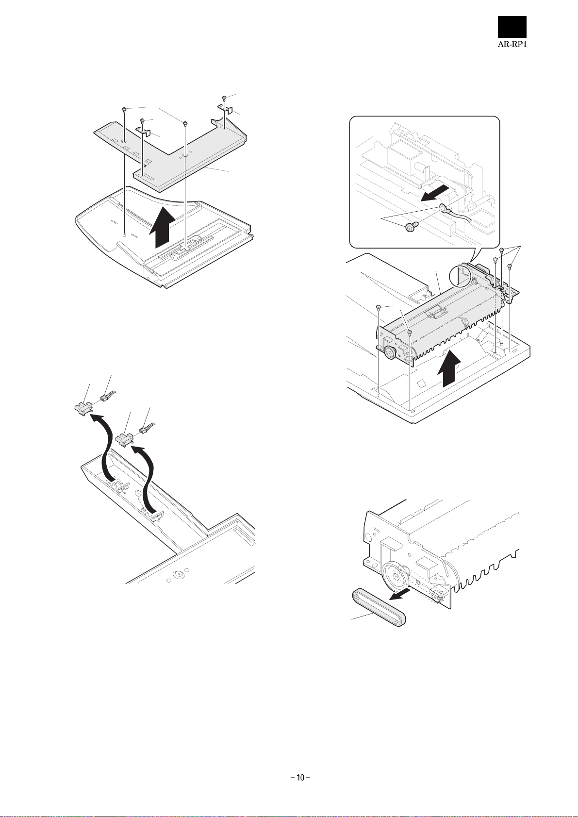
9) Remove the P WB shield plate.
Remove the six screws.
10) Install the SPF harness and the ring core (included together with
the unit).
Pass the S PF harness through the pla te hole from the above and
fix it to the plate with the supplied two hex cap screws. (
Pass the S PF harn ess thr ough t he ring core (
the main PWB connector (CN11) inside the copier. (
), and connect it to
)
)
11) Install the interface harness.
Connect the interface harness from the SPF to the machine and
tighten the screws.
12) Remove the filament tape.
Remove the filament tape at four positions.
1
13) Install the intermediate tray in the case of RSPF.
In the case of RSPF, install the intermediate tray by pushing it to
the inner part.
3
2
★Be careful about the direction of the connector.
Page 5

[4] EXTERNAL VIEW AND
INTERNAL STRUCTURE
1. External view
1
2
5
No. Code Name Type
9 Transport clutch
10
11
12 — Interface PWB — —
13
3
14
15
4
SPF motor Stepping
Gate solenoid
Document length
detection SW
(Short)
Document length
detection SW
(Long)
Book sensor Detects the SPF
——
Drives document
motor
feed on the tray,
transport, and
paper exit roller.
——
Detects the
document length on
the tray.
Detects the
document length on
the tray.
float.
No. Name
1 Document set tray
2 Document guide
3 Document feed section cover
4 Document transp ort section cover
5 Document exit section
2. Internal structure
14
13
15
5
4
3
Sensor, detector, etc.
No. Code Name Type
1 Document set
sensor
2
3
4
5
6
7
8
Open/close sensor Detects open/close
Document width
sensor (A4R, LTR,
A5)
Document width
sensor (B4, B5)
Document width
sensor (WL, TR,
A5R, A4, LT9
Pickup solenoid
Paper entry sensor Detects presence of
Pressure release
solenoid
12
11
10
8
9
6
7
2
1
Detects presence of
documents.
of the paper feed
unit.
Detects the
document width on
the tray.
Detects the
document width on
the tray.
Detects the
document width on
the tray.
——
documents.
——
[5] OPEREATIONAL
DESCRIPTIONS
1. Major parts of the paper fed section
12 3,45678
910111213 141516
No. Part name Operation
1 Document lengt h sensor
(L2)
2 Document lengt h sensor
(L1)
3
4 Document width sensor
(W1, W2, W3)
5 Pickup roller Picks up documents.
6 Paper feed roller Feeds and transports documents.
7 Paper entry sensor
(PAPER)
8 PS roller Makes synchronization between the
9 PS follower roller Makes synchronization betw een the
10 Transport roller Transports documents.
11 Transport follower roller Transport s documents.
12 Paper exit follower roller Discharges documents.
13 Paper exit roller Discharges documents.
14 Reverse gate Opens/closes the document
15 Paper exit gate Separate document exit to the
16 Intermediate tray Discharges documents to the
Detects the document length on the
tray.
Detects the document length on the
tray.
Detects presence of documen t s.
Detects the document width.
Detects transport of do cuments.
document lead edge and the image
lead edge.
document lead edge and the image
lead edge.
reverse path.
intermediate or the paper exit tray.
intermediate tray during document
reverse.
Page 6

2. Out line of operations
3. Document size detection
[Duplex documents]
1) Document set (Document set sensor ON)
2) Document size detection (Document width sensors W1, W2, W3
detect the document width, and document length sensors L1, L2
detect the document length.)
3) Copier COPY key ON
4) SPF motor ON
5) Pickup solenoid ON
6) Pickup roller rotation
7) Paper feed roller rotation
8) Paper entry sensor de t ect s the document presen ce.
9) PS roller rotation
10) Copying (Front surface of document)
11) Transport roller rotation
12) Paper exit roller rotation
1) Document size detection with the document set tray
When documents are set on the document set tray in the auto selec-
tion mode of paper/copy magnification ratio, the document size is
detected and p aper and t he copy mag nificat ion ratio ar e automat ically
selected. When different sizes of documents are set, the max. size is
detected. Th e do cum ent wi dth is det ecte d by the doc ume nt w idth s ensors (W1, W2, W3), and the document length is detected by the document length s ensors (L1, L2 ) t o i dentify the docum ent size. Judg em ent
of the docume nt size is made in a certain t iming after detecting the
document with the document set sensor (W0).
13) Paper exit gate falls down. (Documents are discharged to the
intermediate tray. )
14) Reverse gate falls down.
15) Paper exit roller reverse rotation (Documents are fed to the re-
verse path.)
16) Paper entry sensor detects document pre sence.
17) PS roller rotation
18) Copying (Back surface of document)
19) Transport roller rotation
20) Paper exit roller rotation
21) Paper exit gate falls down (Documents are discharged to the
intermediate tray. )
22) Reverse gate falls down.
23) Paper exit roller reverse rotation (Documents are fed to the re-
verse path.)
24) Paper entry sensor detects document pre sence.
25) PS roller rotation
Document set
size and set
direction
AB
series
Inch
series
(Note) Detection se nsor ON: , OFF:
A5
B5
A5R
A4
B5R
A4R
8.5 x 13"
B4
A3
8.5" x 5.5"
8.5" x 5.5"R
11" x 8.5"
11" x 8.5"R
8.5" x 13"
8.5" x 14"
11" x 17"
Document width sensor
W1 W2 W3 L1 L2
Document
length sensor
26) Paper exit roller rotation
27) Paper exit gate lifts up.
28) Documents are fed to the paper exit tray.
29) Next document
30) SPF motor OFF
(NO)
(YES)
Go to 4).
Page 7

[6] ADJUSTMENTS
(1) RSPF sub scanning direction magnification
ratio adju st me n t
Note: Whe n performing this adjustment, chec k that the CCD unit
is properly instal led.
: When performing this adjustm ent, check tha t the OC mode
adjustment in c opying is complet ed.
1) Place a scale on the document table as shown below, and make a
normal copy to make a test chart.
Note: Since the printed paper is used as the test chart,
place the scale in parallel to both sides.
(2) SPF docu me n t of f ce nt er ad j u st me n t
Note: Whe n performi ng this adju stment, chec k that the pape r off-
center is properly adjusted.
1) Set the c enter po sit ion adj us tme nt test cha rt (ma de by y our se lf) o n
the RSPF.
<Adjustment specifications>
Draw a line in the center of paper. (In the scanning dire ct ion)
2) Make a no rmal copy from the ma nual feed tr ay, and com pare the
copy and the test chart.
If an adjustment is required, perform the following procedures.
3) Execute SIM 50-16.
4) After warming up, shading is performed and the current off-center
adjustment value at each paper feed port is displayed on the display section in two digits.
5) Enter the set value and press the START key.
The entered correction value is started and a copy is made.
<Adjustment specifications>
Mode Specification SIM Set value
SIM
50-16
1 ~ 99
2) Set the test chart to the SPF and make a normal copy.
3) Compare the copy and the test chart.
If an adjustment is needed, perform the following procedures.
4) Execute SIM 8-5. The auto exposure lamp lights up.
5) After warming up, shading is performed. The current correction
value of the front surf ac e sub scann in g dir ecti on ma gnif ic ati on rati o
is displayed on the di splay section in two dig it s.
6) Enter the set value, a nd press the START key.
The entered correction value is stored and a copy is made.
7) Change the duplex document mode to the simplex document
mode.
The MANUAL la mp lights up, and the curren t correction value of
the back surface sub scanning direction magnification ratio is displayed on the display section in two digits.
8) Enter the set value, a nd press the SATART key.
The entered correction value is stored and a copy is made.
<Adjustment specifications>
Mode Spec SIM Set value Set range
SIM
48-5
1 ~ 99
(3) SPF image lead edge position adjustment
1) Set a scale on the OC table as shown below.
Note: Since the printed paper is used as the test chart,
place the scale in parallel to both sides.
2) Make a copy, and use the copied paper as the document and
make a copy from SPF again.
3) Check the cop ied paper. If an adjus tment is requir ed, perform the
following procedures.
4) Execute SIM 50-1.
5) Set the SPF lead edge position set value (Exposure display <MANUAL> ON) s o that the image sim ilar to the adjust ed image at the
OC image lead edge position describ ed previously is prin ted.
<Adjustment specifications>
Adjustment
mode
SIM LED Set value Specification
SIM
50-1
Set
range
1 ~ 99
Page 8

(4) OC (SPF) open/close detection position
adjustment
1) Set a paper of A4 (8.5 x 11") on the OC table.
Check that the document size display on the operation panel is the
same as the set paper size .
2) Close the OC (SPF) so that your hand can be inserted, and remove the paper on the OC table.
The document size disp lay does not change f rom 1).
3) Gradually open the OC (SPF) until the display on the operation
panel is changed. Measure the distance (A) in the figure below
when the disp lay on the op eration p anel is chan ged (all doc ument
size lamps are turned OFF).
Distance (A) = Table glass top - OC (SPF) knob rib
Open.
A
[7] DISASSEMBLY AND ASSEMBLY
1. External fitting section
(Note) Turn the paw in the arrow direction.
1) Check the position where the display checked in 1) is changed.
<Specifications>
OC (SPF) open/close position A : 207 ~ 302mm
4) If the OC (SPF) open/c lose position A is not 207 ~ 302mm, adjust
the open/close sensor installing plate position shown in the figure
below.
Open/close sensor installing plate
(A)
(B)
2. Paper feed unit section
1) Paper feed u n it
Factory setting: The second top mark
Page 9

2) Document transport section cover
1
2
1
3) Document feed section cover
2
3
2
5) Pickup sol eno i d
(Note) Remove section A of the pickup solenoid from the solenoid
arm groove.
2
1
A
4) Sensor PWB
2
3
3
6) Clutch gear ass’y
1
6
1
1
4
5
6
1
3
2
3
3
4
Page 10

7) Pickup roll er as s’ y
(Note) When assembling the pickup roller ass’y 4, check that rib A is
on the rib of the solenoid arm.
A
1
2
4
3. Interface PWB
2
1
3
8) Pick up roller, paper feed roller
4
3
1
4. Document tray section
1) Document tr ay
1
2
3
1
1
2
1
1
Page 11
2) Rack cover
5. Drive frame section
1
3
4
3) Document length sensor SW
2
1
3
1) Drive frame unit
4
2
1
1
2
1
2
1
2) Transport belt
1
Page 12

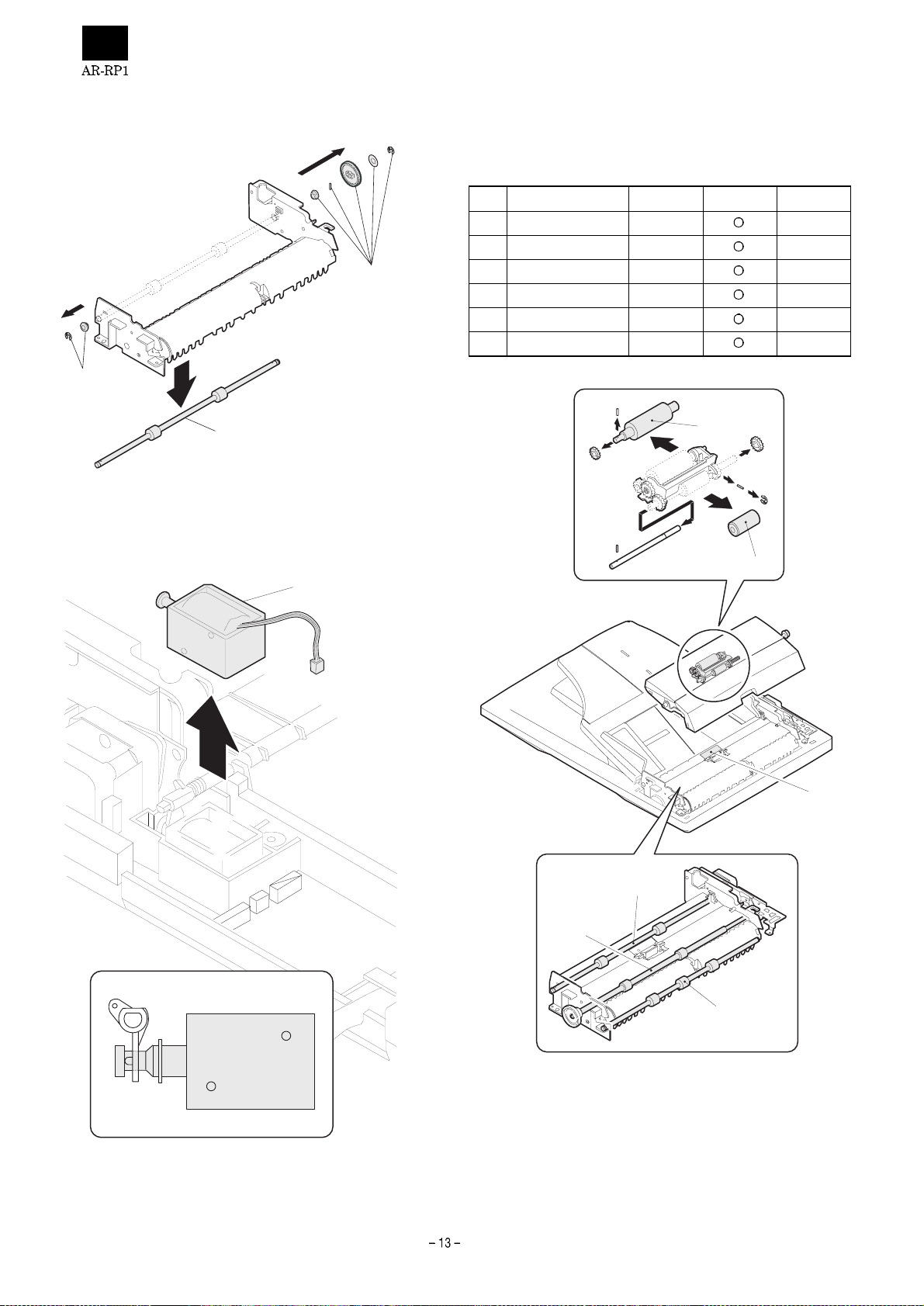
3) Drive frame as s’ y an d d riv e b el t
2
6. Transport section
1) Clutch
1
(Note) When assembling, check that the rib is in the clutch groove A
and fix it with E-ring.
3
3
A
1
4) Pressure re le as e so l en oid
3
2
5) SPF motor
1
2
1
2) Transpor t rol ler gear
1
1
1
3
2
Page 13

3) Reverse gate
4
6) PS roller
1
3
2
1
7) Paper feed paepr guide upper
2
1
(Note) When assembling, check that the paper feed paper guide
upper 2 is securely set to rib A and boss B.
4) Transpor t rol l e r
5) Book sensor
1
2
1
1
B
A
1
8) Paper feed paper guide upper
2
1
Page 14
9) Paper exit roller
1
[8] MAINTENANCE
1. Maintenance parts
No. Name Work item Service call Remark
1 Pickup roller Cleaning
2 Separation pad Cleaning
1
3 Paper feed roller Cleaning
4 PS roller Cleaning
5 Transport roller Cleaning
6 Paper exit roller Cleaning
10) Gate solenoid
2
1
3
1
2
(Note) When assemb ling, check tha t the paper exit ga te hook is set
in the solenoid groove.
6
5
4
(Note) When performing maintenance, refer to [6] DISASSEMBLY
AND ASSEMBLY.
Page 15
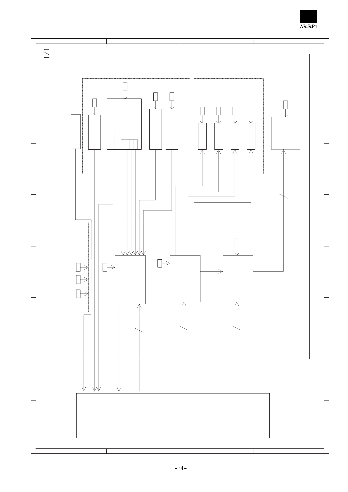
D
C
B
A
1
5V2
5V2
SENSER
24V
CLH
24V
RSOL
24V
PSOL
RSPF ONLY
24V
GSOL
RSPF ONLY
SOL./CLU.
24V
MOT
5V2
5V2
2345678
Senser PWB
COVER OPEN
PAPER
COVER
W0L1W2
W1
W3
L2
RPF/RSPF UNIT
2 1
3
AA/B
4
24V
B/
PAPER
5V1
COVER
IC001
DATA SELECTOR
3
Y
24V
5V2
5V1
COPIER
1. Block diagram
[9] ELECTRICAL SECTION
SELA
SELB
SELB
24V
IC003
DRIVER ARRAY
5
CLH
RSOL
PSOL
GSOL
PDOWN
PDOWN
IC002
MOTOR DRIVER
4
MOTA
MOTB
MOTBN
MOTAN
INTERFACE PWB
8 7 6 5 4
D
C
B
A
Page 16

D
C
B
A
1
L2
L1
Senser PWB
PAPER FEED UNIT
CN101
(PHR-7)
COVER
5V
2
W3
W1
W0
W2
3
1
5
4W2
6
PSOL
LGND
7
1
3
2
DF3-3S-2C
2345678
GY
OR
6
COVER
2
GY
7
4
5
3
PHNR-7-H
W2
W3
W1
LGND
5
4
1
3
BU2P-TR-P-H
PHNR-7-H
OR
25V
1W0
6
7
BU7P-TR-P-H
GY
BL
LB
1
2
PHNR-2-H
PSOL/
24V1
2
1
PHNR-2-H
3
4
5
6
LGND
5V
L2
LGND
1
2
4
3
BU6P-TR-P-H
Original Tray
RSOL
CLH
2
3
1
DF3-3S-2C
OR
1
2
PHNR-6-H
L1
5V
5
6
PHNR-6-H
PAPER
3
2
1
PHR-3
SMR-02V(B)
SMR-02V(N)
24V1
24V1
1
SMP-02V(B)
RSOL/
CLH/
1
2
2
SMP-02V(N)
GSOL
RSPF ONLY
4
PHR-6
2 1
3
MOT
3
6
1
5
2
PK PK
OR
BL BL
1
7
16
5V2
W0
COVER
(PHDR-22VS)
CN002
Interface PWB
24V
PSOL
24V
(PHDR-24VS)
CN001
24
22
19
RD
PL
RD
24V
24V
PSOL
3
2
1
CL211-0211-6
2. Actual wiring
PPC
RD
GY
BR BR
PL PL
LB LB
11
9
19
13
W3
LGND
W1
MOTBN
CLH
MOTB
RSOL
MOTA
GSOL
13
PL
MOTAN
14
15
18
17
16
20
PL
BL
BR
BR
PL
PK
GY
BL
10
2
PSOL/
24V1
PGND
LGND
PGND
LGND
5
23
6
21
GY
GY
LB
GY
GY
OR
BL
OR
GY
LB
17
4
15
20
3
21
LGND
PAPER
8
BL
L2
COVER
10
5V2
5V2
L1
LGND
Y
COVER OP EN
PDOWN
SELA
SELB
3
2
12
1
11
BR
BR
BR
LB
BL
PL
PL
BR
GY
RD
18
5
12
22
LEDSPPD
PAPER
LGND
24V1
5V1
SELC
5V2
4
9
7
FG
INTERNAL SPF/RSPF
OR
OR
PK
LB
RD
6
14
CLH/
24V1
PL
RD
2
1
8
RSOL/
EARTH
GSOL/
24V1
(PHR-2)
CN004
PLATE
PLATE
SPF FIXING
CN005
CN003
PK
RD
RD
BL
PL
LB
1
2
B/
B
(PHR-7)
(PHR-3)
1 COVER OPEN
2LGND
ORBRGY
1
2
3
A
35V2
3
A/ 4
DF3-3S-2C
7
6
24V1 5
N.C.
24V1
COVER OPEN
GP1A71A1
SELC
Y
COVER
MOTAN
MOTA
CLH
6
MOTBN
MOTB
9
8
7
10
GSOL
RSOL
5
4
PAPER
LGND
PGND
PGND
LGND
14
11
16
13
15
12
SELB
COVER OP EN
SELA
PDOWN
19
18
17
5V2
5V1
23
20
22
24
21
FG
25 N.C.
SRA-21T-4
8 7 6 5 4
D
C
B
A
Page 17

D
CN002-2
CN002-6
CN002-8
PSOL/
9
O116O215O314O413O512O611O7
COM
IC003
I11I22I33I44I55I66I7
PSOL
CN001-1 9
CN004-2
CLH/
RSOL/
GSOL/
24V1
10
GND
BA12003B
7
8
CLH
RSOL
GSOL
PDOWN
CN001-1 7
CN001-1 5
CN001-1 3
CN001-1 1
5V1
IC002
9.1KJ
R005
47kJ
R009
47kJ
R008
1
2345678
24V1
C
CN003-4
CN003-2
CN003-3
CN003-1
A/
B/
B
A
C020
0.1µF
C001
47uF/35 V
+
7
2
VSA
TdA
12
VSB
TdB13RSA
9
R001
11
1
8
18
OUTA
OUTA
OUTB
REFA
3
C007
2200pF
R006
2.4kJ
1.5J(1W)
CN001-20
CN001-18
CN001-14
CN001-16
MOTAN
MOTA
MOTB
MOTBN
5
6
16
17
INA
INA
INB
OUTB
REFB
14
R007
INB
GA
GB
RSB
10
C008
2200pF
2.4kJ
R002
C004
R003
C006
C005
SLA7027M
4
15
1.5J(1W)
0.1uF
1.5KJ
470pF
470pF
B
CN001-3
Y
D007
D008
1SS133
1SS133
5V1
1SS133x3
D006
5V1
D005
D004
5
6
Y
W
IC001
D04D13D22D31D415D514D613D712A11B10C9G
R016
5V1
5V1
10kJ
R015
R014
R013
R012
R011
R010
CN001-1 0
CN001-8
CN001-1 2
COVER
PAPER
COVER OPEN
W1
W0(Docume nt Size Senser)
L2
W3
74HC151
7
1000pFx6
C014
C013C009
C011
A
CN001-1
CN001-4
CN001-2
SELA
SELC
SELB
7
C01
1000pFx3
C016
C015
D002 D003
1SS133 x3
D001
DSPF
C012
C010
C003
5V1
IC001
100000pF
16
8
2 1
3
74HC151AP
CN002-10
CN002-12
CN002-14
CN003-5
CN003-6
CN004-1
24V1
ICP001
ICP-N38
C019
0.1µF
24V
24V
CN001-2 4
CN001-2 2
CN002-1
CN002-3
CN002-4
TO 5V1
5V1
5V2
PGND
PGND
CN001-2 1
CN002-5
CN005-3
CN002-1 9
CN002-2 0
LEDSPPD
220J(1/4W)
LGND
R004
C018
10uF/16 V
+
C002
10uF/16 V
+
LGND
LGND
1. Interface PWB
3. Circuit diagram
CN001-7
CN001-9
CN001-5
CN001-6
C021
CN005-1
CN002-16
CN002-18
CN002-11
CN002-9W2CN002-13
CN002-7
CN002-15L1CN002-17
PSOL/
5V2
CLH/
RSOL/
24V1
24V1
24V1
COVER
PAPER
LGND
246
8
10121416182022
CN001-2 3
5V2
LEDSPPDW0W2W3W1L1L2
5V2
13579
(PHDR-22VS)
CN002
CN002-2 1
CN002-2 2
CN005-2
SELB
SELAYLGND
123456789
(PHDR-24VS)
CN001
SELC
LGND
1113151721
PAPER
COVER
COVER OPEN
10
12141618202224
5V1
5V2
PDOWN
11131517192123
LGND
LGND
LED POWER
LGND
LGND
19
MOTB
MOTBN
MOTA
MOTAN
24V
24V
CLH
PSOL
GSOL
RSOL
PGND
PGND
(PHR-3)
CN005
(PHR-2)
CN004
(PHR-6)
CN003
COVER OPEN
3
1
2
24V1
GSOL/
1
2
BB/AA/24V1
12345
W1W2W3
W0
L1
HL
LH
LL
HH
L
LLL
L
LLH
HHH
SELA
24V1
6
SELB
7N.C.
SELC Y
MATRIX
Senser
CN005
(PHR-3)
CN003
L2
SPF/ /RSPF
L
H
24V1
IC003
CN004
(PHR-7)
L
HH
H
100000pF
9
(PHR-2)
8
CN001
(PHDR-24VS)
PARTS VIEW
CN002
(PHDR-22VS)
8 7 6 5 4
D
C
B
A
Page 18

D
1
C
B
A
23456
2 1
3
78
2. Sensor PWB
3. Circuit diagram
D
8 7 6 5 4
C
B
A
Page 19

4. Parts arrangement
[Parts surface]
CLH/
RSOL/
24V1
24V1
24V1
COVER
PAPER
LGND
LGND
6
8
10
12
14
16
18
20
22
LEDSPPD
W0
W2
W3
W1
L1
L2
LGND
LGND
(PHDR-22VS)
CN002
19
13
15
21
17
5
7
9
11
5V2
4
5V2
3
PSOL/
2
5V2
1
(PHR-2)
CN004
24V1
GSOL/
1
2
(PHR-6)
CN003
N.C.
24V1
24V1
7
5
6
4
B
B/
A
A/
1
2
3
[Solder surface]
(PHDR-24VS)
CN001
12
3456
SELAYLGND
SELB
SELC
LGND
789
11131517192123
5V1
5V2
PDOWN
GSOL
RSOL
10
12141618202224
PAPER
COVER
MOTB
MOTBN
COVER OPEN
CLH
MOTA
PSOL
MOTAN
PGND
PGND
24V
24V
(PHR-3)
CN005
1
3
2
LGND
5v2
COVER OPEN
Page 20

COPYRIGHT ã 1999 BY SHARP CORPORATION
All rights reserved.
Printed in Japan.
No part of this publication may be reproduced,
stored in a retrieval system, or transmitted.
In any form or by any means,
electronic, mechanical, photocopying, recording, or otherwise,
without prior written permission of the publisher.
SHARP CORPORATION
Information Systems Group
Quality & Reliability Control Center
Yamatokoriyama, Nara 639-1186, Japan
1999 June Printed i n Japan
 Loading...