

Page 1

CODE: 00ZARPX1//A1E
Printer I/F kit
AR-PX1
MODEL AR-PX2
AR-PX1
(for North &
South Amer ica)
CONTENTS
[1] OUTLINE . . . . . . . . . . . . . . . . . . . . . . . . . . . . . . . . . . . . . . . . . . . . . 1
[2] SET UP . . . . . . . . . . . . . . . . . . . . . . . . . . . . . . . . . . . . . . . . . . . . . . . 1
[3] BLOCK DIAGRAM . . . . . . . . . . . . . . . . . . . . . . . . . . . . . . . . . . . . . . 4
[4] ACTUAL WIRING CHART . . . . . . . . . . . . . . . . . . . . . . . . . . . . . . . . 6
[5] CIRCUIT DIAGRAM . . . . . . . . . . . . . . . . . . . . . . . . . . . . . . . . . . . . . 7
PARTS GUIDE
This document has been published to be used
for after sales service only.
The contents are subject to change without notice.
Page 2
AR-PX1
AR-PX1/PX2 Installation Manual
FOR USE WITH COMPATIBLE SHARP COPIERS.
SEE SHARP COPIER INSTALLATION MANUAL TO DETERMINE SUITABILITY.
ACCESSORY
I.T.E.
9K11
[1] OUTLINE
This kit is used to connect the printer controller with the scanner and
the printer section in the machine.
1. Kit composition
This kit is composed of the following major parts:
• Printer I/F PWB
• Printer I/F connector unit
• Internal connection cable
• External connection cable
2. Outline of operations
(Printer mode)
Each color image data of 8bit of Y/M/C/K outputted from the print
controller is converted into the engine logic level in the printer I/F
PWB.
(Scanner mode)
Each color image data of 8bit of R/G/B scanned by the scanner is
inputted to the printer I/F PWB, and converted into the differential
output and sent to the print controller.
(Circuit system)
High-speed data transmission/reception is performed between the engine and the print controller. For that, the differential I/O system is
employed to increase the noise margin.
(Parts list)
No. Part name Quantity
1 Printer I/F PWB 1
2 Wake up signal harness (connected to the printer I/F PWB) 1
3 Printer I/F connector unit 1
4 Flat cable 1
5 Flat cable clip 1
6 Harness clip 1
7 Screw (M3) 4
8 Printer cable 1
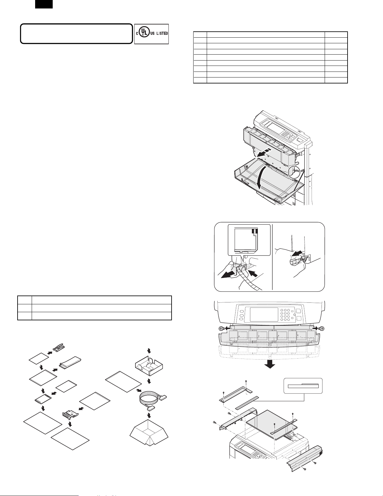
2. Parts assembly
1) Open the front cabinet, and pull out the toner hopper unit.
2) Remove the toner hopper connector cover, and remove the toner
hopper connector.
[2] SETUP
(Necessary tools)
1 Screwdriver
2 Short screwdriver
3 Nippers
1. Unpacking
3) Remove the toner hopper unit.
4) Remove the right upper cabinet.
– 1 –
Page 3
AR-PX1
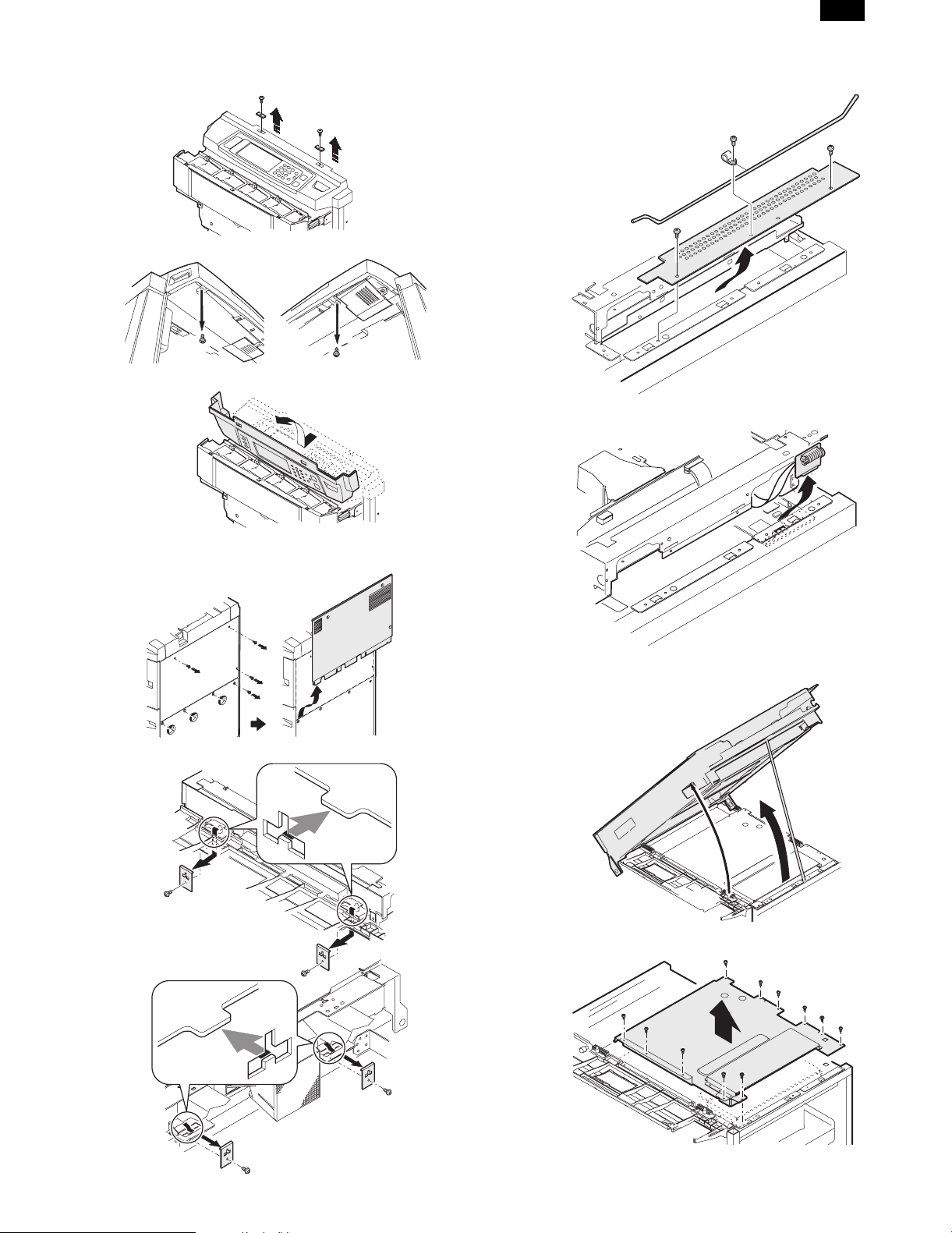
5) Remove the left upper cabinet.
6) Remove the operation unit.
10) Remove the scanner (reading) unit hold shaft and the ICU PWB
shield plate.
11) Remove the CCD flat cable connector.
7) Remove the original table glass.
8) Remove the rear cabinet.
9) Remove the scanner (reading) unit fixing angle.
12) Open the scanner (reading) unit and fix it with the hold shaft.
13) Remove the ICU PWB cover.
– 2 –
Page 4
AR-PX1
14) Remove the left side cabinet.
15) Remove the cabinet angle. This angle is unnecessary when
removed. However, the screw which was fixing the angle is required to fix the printer I/F connector unit later.
16) Open the printer I/F connector window of the left rear cabinet.
(Cut the cabinet with nippers.)
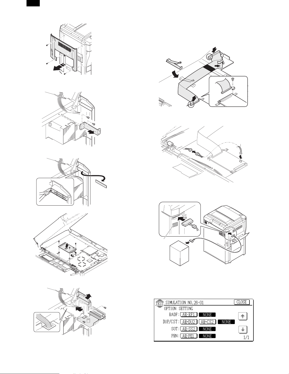
19) Use the flat cable to connect the printer I/F PWB and the printer
I/F unit. At that time, be careful of the connector direction. Also
check that the flat cable protector section (black section) passes
through the chassis edge. Bend the flat cable at the right angle
in two positions. Fix the flat cable with the cable clamp of the
printer I/F unit section and the flat cable clip.
20) Connect the wake up signal harness connector to the printer I/F
PWB, and connect the other end to the main harness wake up
signal connector.
17) Attach the printer I/F PWB with the accessory screw.
18) Use the screw noted in procedure 15) and attach the printer I/F
connector unit.
21) Install all the parts that were removed to their original positions.
22) Connect the main unit and the printer controller with the printer
cable.
Caution label
23) Attach the caution label to the cabinet.
3. Setting
1) Turn on the power of the unit.
2) Enter the simulation 26-1 mode.
(NOTE)
When attaching the I/F connector mounting plate, be careful not to
apply an excessive stress to the connector which is passed under the
I/F connector mounting plate.
3) Press "PRN: AR-PE1" button. (Communication between the unit
and the printer controller is allowed.)
4) Cancel the simulation mode.
– 3 –
Page 5
AR-PX1
4. Other
A. Printing Documents from the Computer
In most cases, it is not necessary to use the operation panel when
printing documents from the computer. When a document is sent to
the printer from the computer, the printer will automatically print the
document. However, following the procedure specified below can
help ensure that documents are printed accurately. The procedure
assumes that the printer has been properly connected to a computer,
and that a printer driver has been installed.
1) Check the operation panel to confirm that the ON LINE indicator is
lit. If the ON LINE indicator is not lit, press the PRINT key to select
the printer mode and then press the "ONLINE" key on the touch
panel to set the printer to the on-line condition.
2) Check the paper tray(s) to ensure that the desired paper is
loaded.
3) Using the computer and any appropriate application software, load
the document to be printed, set any desired features using the
installed printer driver, and give the command to print the document. If necessary, refer to the documentation for the computer
and/or the application software for help on issuing the necessary
commands.
4) The printer will print the document.
(1) Selecting the Online Mode
If the printer is in the offline mode, printing cannot be performed. To
select the online mode, use the procedure below.
1) If the printer is in the copier mode, press the PRINT key to select
the printer mode.
The basic screen of the printer mode will appear.
2) Press the "ONLINE/OFFLINE" key on the touch panel to switch
the printer to the online mode.
3) To select the copier mode, press the COPY key.
B. Tray Select
(1) Tray Selection
The "PAPER SELECT" key on the touch panel can be used to
change paper trays when printing has stopped for one of the following
reasons.
• In ‘Auto Select’ paper source selection mode, all trays on the
printer configured for the requested paper size are out of paper or
no trays on the printer are configured for the requested paper size.
• If a paper source has been specified, the requested tray on the
printer has run out of paper.
In most cases it will be best to load or re-load the printer with the
appropriate paper size and continue printing. If it is preferable to
continue printing from a different tray (possibly containing a different
size paper than requested by the computer), follow the procedure
below.
Tray Change Procedure:
1) Press the "ONLINE/OFFLINE" key on the touch panel to set the
printer to an offline state.
2) Press the "PAPER SELECT" key to select the desired paper tray.
3) Press the "ONLINE/OFFLINE" key to return the printer to an online state. The printer will begin printing from the selected tray.
NOTES: Selecting a tray containing a different size or orientation of
paper than that specified by the computer may result in the
pages being clipped to fit the physical paper size.
Note that using the "PAPER SELECT" key to select a new
paper tray overrides any selection previously made using
the printer driver configuration menus.
To cancel the print, use the operation panel of the Printer
Controller.
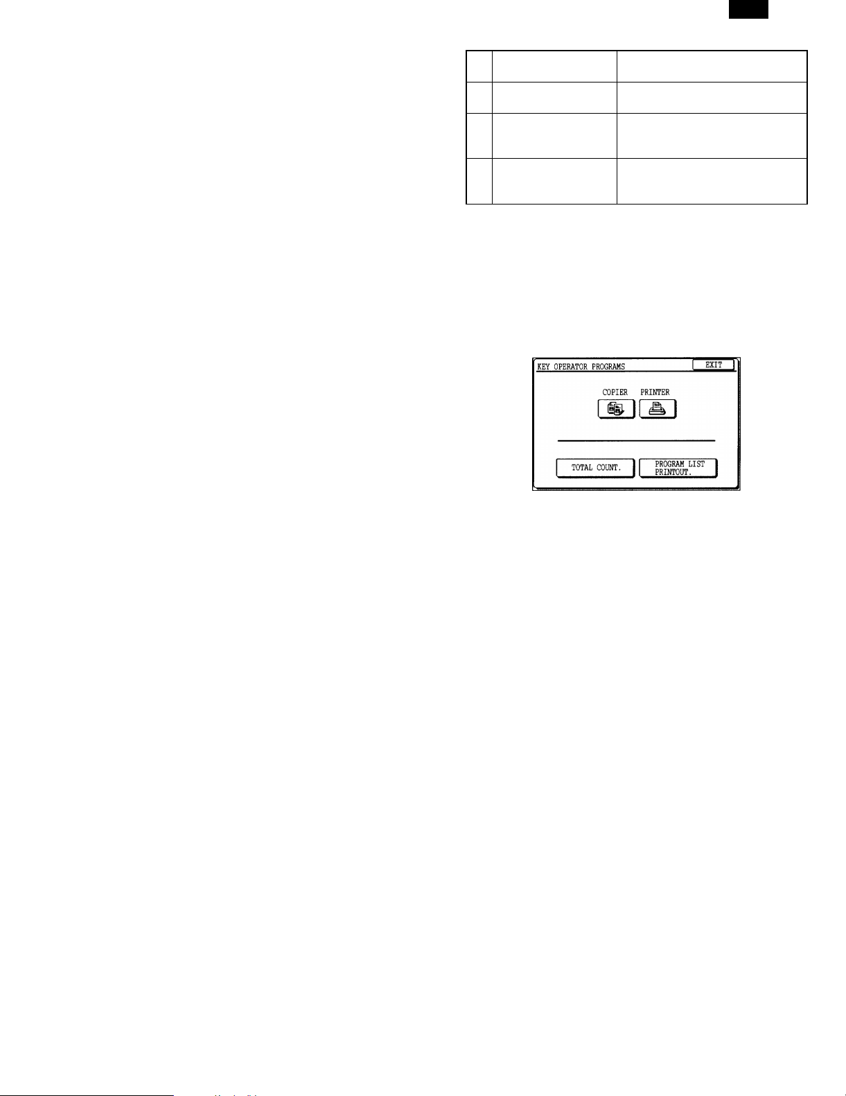
C. Key Operator Programs
Four key operator programs are available which allow a key operator
to adjust certain printer operating conditions. These programs are
listed as below.
1 Enable Bypass-Tray
Size Detection
2 Enable Bypass-Tray
Type Detection
3 Prohibit Bypass-Tray
Selection
4 Prohibit Auto Tray
Switching
Key operator programs governing printer features and functions can
be called in the same manner as the key operator programs governing copier features.
For general information on accessing key operator programs, including registration of a key operator code number, refer to the Key
Operator’s Guide in the copier manual.
If the printer function kit has been expanded, the "PRINTER" key will
be displayed on the touch panel after the key operator code number
is entered. Press the "PRINTER" key to access the key operator
programs for the printer features.
Enables or disables paper size
detection for the bypass tray.
Enables or disables paper type
detection for the bypass tray.
Enables/disables bypass tray
selection in the ’Auto Tray
Switching’ mode.
Enables/disables automatic
switching between paper trays
during printing when paper runs out.
(1) Enable Bypass-Tray Size Detection
This program is used to enable or disable paper size detection of the
bypass tray in the printer mode. This setting does not affect the paper
size detection in the copier mode.
To enable paper size detection of the bypass tray in the printer mode,
press the "ENABLE BYPASS-TRAY SIZE DETECTION" box to display a check mark.
To disable paper size detection, press the checked box again to clear
the check mark.
NOTE: If size detection of the bypass tray is disabled, paper in the
bypass tray will always be treated as the largest allowable
size paper (either 11" x 17" or A3). If an image larger than
the paper in the bypass tray is printed, a malfunction may
occur. Be careful when disabling the size detection.
(2) Enable Bypass-Tray Type Detection
This program is used to check the paper type selection for the bypass
tray at the machine with that selected at the printer driver when
printing from the bypass tray.
• When the check mark is on, the paper type selections at the
machine and at the driver will be checked. If both do not match,
auto paper feed will not be activated. If they match and the other
conditions for the auto paper feed are satisfied, the auto paper
feed will be activated.
• When the check mark is off, the paper type selection for the
bypass tray at the machine will be disregarded. Even if the selection is made at the machine, the selection at the printer driver will
override it.
When using with the check mark off, be sure not to select wrong
paper type. If the wrong paper type is selected, a misfeed or a
malfunction may occur.
To enable paper type detection of the bypass tray, press the
"Enable Bypass-Tray Type Detection" check box to display a check
mark. To disable paper type detection, press the checked box
again to clear the check mark.
– 4 –
Page 6

AR-PX1
(3) Prohibit Bypass-Tray Selection
If this program is set, the bypass tray will not be selected for a print
job that specifies auto paper selection or during auto tray switching.
To prohibit bypass tray selection, press the "PROHIBIT BYPASSTRAY SELECTION" box to display a check mark.
To restore bypass tray selection, press the checked box again to
clear the check mark.
(4) Prohibit Auto Tray Switching
This program prevents automatic switching between paper trays in
print jobs. This program does not affect the auto tray switching function in the copier mode.
To prohibit automatic tray switching, press the "PROHIBIT AUTO
TRAY SWITCHING" box to display a check mark.
To restore automatic tray switching, press the checked box again to
clear the check mark.
D. General Operation Steps for the Scanner Use
To scan, process or edit images and documents by using the
machine as a scanner, a TWAIN application software (such as Adobe
PhotoShop) is required.
1) Install the required driver software in your computer in accordance
with the operation manual for the Printer Controller.
2) Press PRINTER key to display the printer mode screen.
3) Check the operation panel to confirm that the ONLINE Key is
selected. If not, touch the ONLINE key to be in the online status.
4) Place the original on the document glass or in the document
feeder (optional).
NOTE: Even if the multiple originals are set in the document feeder,
5) Acquire the image or the document using the application software.
6) Edit or store the scanned image or document. For the details,
the scanning is processed by one page at each operation
and it is required to repeat the below mentioned step 5) by
the numbers of the original pages.
For the details, refer to the operation manual supplied with the
application software.
refer to the operation manual supplied with the application
software.
– 5 –
Page 7

AR-PX1
[4] ACTUAL WIRING CHART
WAKE UP RELAY HARNESS
MAIN HARNESS R (3PIN)
OP PANEL
– 6 –
Page 8

AR-PX1
CN543-13
1/2
C/R DATA4A
C/R DATA4B
3
2
1Y
1A
IC107
1
3
Y1
A1
IC117
2
1
+3.3V +3.3V
CN543-17
CN543-18
CN543-15
CN543-16
CN543-19
CN543-20
CN543-14
C/R DATA6B
C/R DATA5A
C/R DATA5B
C/R DATA7B
C/R DATA7A
C/R DATA6A
100J
100J
100J
100J
R102
R103
R112
6
1Z
7
6
Y2
A2
B1
5
4
8
10
14
5
11
13
2Y
3Y
4Y
2Z
3Z
4Z
4A
3A
2A
G
9
4
15
7
11
8
Y4
Y3
GND
74LCX32
B413A4
VCC
B2
B3
A3
0.1uF
9
C136
12
14
10
2
1
GND
1A
G
12
16
1B
VCC
DS90LV031A
1Y
IC101
0.1uF
C119
3
+3.3V
R113
10KJ
+3.3V
R111
6
7
2A
2B
2Y
5
8
10
14
9
15
3A
4A
3B
4B
GND
VCC
G
4Y
3Y
G
DS90LV032A
4
12
16
13
11
0.1uF
C102
CN543-37
CN543-39
CN543-35
CN543-33
M/G DATA4A
M/G DATA4B
3
2
1Y
1A
IC125
1
+3.3V
3
Y1
A1
IC120
2
1
+3.3V
CN543-40
CN543-38
CN543-36
CN543-34
M/G DATA6A
M/G DATA7A
M/G DATA5A
M/G DATA7B
M/G DATA6B
M/G DATA5B
100J
100J
100J
100J
R142
R143
R154
6
2Y
1Z
2A
7
6
Y2
B2
A2
B1
5
4
8
10
14
5
11
13
3Y
4Y
2Z
3Z
4Z
GND
G
4A
3A
G
VCC
DS90LV031A
9
15
7
11
8
Y4
Y3
GND
74LCX32
VCC
B4
A4
B3
A3
9
C133
14
13
12
10
IC115
4
12
16
0.1uF
C117
+3.3V
R144
10KJ
+3.3V
0.1uF
R155
2
6
1
7
1A
2A
1B
2B
2Y
1Y
5
3
8
10
14
9
15
3A
4A
3B
4B
GND
VCC
G
4Y
3Y
G
DS90LV032A
4
16
12
13
11
0.1uF
C100
CN543-67
CN543-65
CN543-69
CN543-64
CN543-66
CN543-68
CN543-63
Y/B DATA4B
Y/B DATA4A
3
2
1Y
1A
IC106
1
+3.3V
3
Y1
A1
IC118
2
1
+3.3V
CN543-70
Y/B DATA6A
Y/B DATA5A
Y/B DATA7A
Y/B DATA5B
Y/B DATA6B
Y/B DATA7B
100J
100J
100J
100J
R108
R101
R109
DS90LV031A
C141
R100
2
6
10
14
1
7
9
15
1A
2A
3A
4A
1B
2B
3B
4B
G
4Y
3Y
2Y
1Y
IC100
0.1uF
3
+3.3V
R110
10KJ
+3.3V
4
5
12
13
11
6
10
14
8
5
11
13
2Y
3Y
4Y
1Z
2Z
3Z
4Z
GND
G
4A
3A
2A
G
VCC
9
7
4
15
12
16
7
11
8
6
Y4
Y3
Y2
GND
74LCX32
VCC
B413A4
B3
A3
B2
A2
B1
0.1uF
9
5
4
C135
14
12
10
CN543-83
CN543-89
CN543-84
CN543-85
CN543-86
CN543-87
CN543-88
CN543-90
K DATA4B
K DATA4B
K DATA5B
K DATA5B
K DATA6B
K DATA6B
K DATA7B
K DATA7B
100J
100J
100J
100J
R141
R140
R151
8
GND
VCC
G
DS90LV032A
IC114
16
0.1uF
C130
+3.3V
R153
10KJ
+3.3V
R152
2
6
1
7
1A
2A
1B
2B
2Y
1Y
5
3
8
10
14
9
15
3A
4A
3B
4B
GND
VCC
G
G
4Y
3Y
11
DS90LV032A
4
12
16
13
0.1uF
C129
*NR105
DR7
DR4
DR5
DR6
CN541-20
CN541-17
CN541-18
CN541-19
CN543-11
CN543-7
CN543-8
CN543-5
CN543-10
CN543-6
CN543-12
CN543-9
C/R DATA1B
C/R DATA0A
C/R DATA2B
C/R DATA0B
C/R DATA3B
C/R DATA2A
C/R DATA3A
C/R DATA1A
6
10
14
3
5
11
2
1Y
1A
IC109
1
3
Y1
A1
IC116
1
+3.3V +3.3V
*NR101
13
2Y
3Y
4Y
1Z
2Z
3Z
4Z
4A
3A
2A
9
7
15
7
11
8
6
Y4
Y3
Y2
GND
74LCX32
B4
A4
VCC
B2
A2
B3
B1
A3
5
4
C131
2
9
13
12
14
10
DR3
DR0
DR1
DR2
CN541-16
CN541-13
CN541-14
CN541-15
*NR102
BDC6
BDC7
BDC5
BDC4
CN541-52
CN541-53
CN541-51
CN541-50
100J
100J
100J
100J
R107
R118
R117
DS90LV031A
C120
R106
2
6
10
14
1
7
9
1A
1Y
IC103
0.1uF
3
+3.3V
R119
10KJ
+3.3V
*NR103
BDC0
CN541-46
15
2A
3A
4A
1B
2B
3B
4B
G
4Y
3Y
2Y
4
5
13
11
BDC2
BDC1
BDC3
CN541-48
CN541-47
CN541-49
8
GND
G
G
VCC
4
12
16
0.1uF
*NR109
DG5
DG4
DG6
DG7
CN541-27
CN541-28
CN541-26
CN541-25
CN543-26
CN543-30
CN543-28
CN543-31
CN543-27
CN543-29
CN543-25
M/G DATA0B
M/G DATA2B
M/G DATA0A
M/G DATA1B
M/G DATA3B
M/G DATA3A
M/G DATA1A
M/G DATA2A
6
10
14
3
5
11
2
8
1Y
GND
1A
IC123
VCC
G
DS90LV032A
1
12
16
0.1uF
C103
3
Y1
A1
IC119
1
+3.3V +3.3V
*NR107
13
2Y
3Y
4Y
1Z
2Z
3Z
4A
3A
2A
9
7
15
7
11
8
6
Y4
Y3
Y2
GND
74LCX32
B4
A4
VCC
B2
A2
B3
B1
A3
5
4
C132
2
9
13
12
14
10
DG3
DG0
DG2
DG1
CN541-24
CN541-21
CN541-23
CN541-22
*NR106
BDM4
BDM7
BDM5
BDM6
CN541-58
CN541-61
CN541-59
CN541-60
CN543-32
100J
100J
100J
100J
R138
R139
R149
8
2
4Z
G
G
4
12
0.1uF
1
GND
1A
1B
VCC
DS90LV031A
1Y
IC113
16
0.1uF
C118
3
+3.3V
R150
10KJ
+3.3V
*NR104
BDM2
BDM1
BDM0
CN541-55
CN541-54
R148
6
10
14
7
9
15
2A
3A
4A
2B
3B
4B
4Y
3Y
2Y
4
5
13
11
BDM3
CN541-56
CN541-57
*NR112
DB7
DB5
DB4
DB6
CN541-36
CN541-34
CN541-33
CN541-35
CN543-59
CN543-55
CN543-60
CN543-56
CN543-61
CN543-58
CN543-57
Y/B DATA1A
Y/B DATA2A
Y/B DATA0A
Y/B DATA2B
Y/B DATA0B
Y/B DATA3A
Y/B DATA3B
Y/B DATA1B
6
10
14
3
5
11
2
8
1Y
GND
1A
IC108
VCC
G
G
DS90LV032A
1
12
16
0.1uF
C101
3
Y1
A1
IC121
1
+3.3V +3.3V
*NR111
13
2Y
3Y
4Y
1Z
2Z
3Z
4A
3A
2A
9
7
15
7
11
8
6
Y4
Y3
Y2
GND
74LCX32
B4
A4
VCC
B2
A2
B3
B1
A3
5
4
C134
2
9
13
12
14
10
DB2
DB3
DB1
DB0
CN541-31
CN541-32
CN541-30
CN541-29
*NR110
BDY6
BDY4
BDY5
BDY7
CN541-66
CN541-67
CN541-69
CN541-68
CN543-62
100J
100J
100J
100J
R104
R105
8
4Z
GND
G
G
VCC
DS90LV031A
IC102
4
12
16
0.1uF
C139
+3.3V
R116
10KJ
+3.3V
0.1uF
*NR108
R115
2
6
10
14
1
7
9
15
1A
2A
3A
4A
1B
2B
3B
4B
4Y
3Y
2Y
1Y
5
3
13
11
BDY3
BDY2
BDY1
BDY0
CN541-65
CN541-64
CN541-63
CN541-62
*NR100
BDK6
BDK4
BDK7
BDK5
CN541-43
CN541-44
CN541-42
CN541-45
CN543-75
CN543-76
CN543-77
CN543-78
CN543-79
CN543-80
CN543-81
CN543-82
K DATA0B
K DATA0B
K DATA1B
K DATA1B
K DATA2B
K DATA2B
K DATA3B
K DATA3B
100J
100J
100J
100J
R145
R136
R146
R114
8
GND
VCC
G
G
DS90LV032A
4
12
16
0.1uF
C128
+3.3V
R137
2
6
1
7
1A
2A
1B
2B
2Y
1Y
IC112
5
3
+3.3V
R147
10KJ
*NR113
BDK0
BDK2
BDK3
BDK1
CN541-38
CN541-40
CN541-41
CN541-39
8
10
14
9
15
3A
4A
3B
4B
GND
VCC
G
4Y
3Y
G
DS90LV032A
4
12
16
13
11
0.1uF
C127
PRT-I/F P WB
[5] CIRCUIT DIAGRAM
CN543-4
CN543-2
CN543-1
CN543-3
CN543-42
CN543-41
ECLKB
ECLKA
HSYNCB
VSYNCB
VSYNCA
HSYNCA
6
10
14
2
3
5
11
13
2Y
3Y
4Y
1Y
1Z
2Z
3Z
4Z
4A
3A
2A
1A
IC104
1
+3.3V
+3.3V
R122
10KJ
*TP102
R120
680J
+3.3V
*R125
SCLKB6
CN541-10
G
9
7
4
15
3
Y1
B1
A1
IC105
2
1
+3.3V
R121
360J
560pF
C114
*TP100
*R127
PRT_P
CN541-6
/PRT_SB
PRT_PB
8
GND
DS90LV031A
G
VCC
12
16
0.1uF
C104
+3.3V
7
11
8
6
Y4
Y3
Y2
GND
74LCX32
B4
A4
VCC
B2
B3
A2
A3
0.1uF
5
4
9
C105
13
12
14
10
*TP101
*R126
/PRT_S
CN541-7
+3.3V
*C107 *C106
IC111
*R124
3
Y1
A1
2
1
SSYNCB6
CN541-11
7
11
8
6
Y4
Y3
Y2
GND
B413A4
VCC
B2
A2
B3
B1
A3
5
4
9
12
14
10
*R123
HSYNCB6
CN541-12
CN543-43
CN543-44
CN543-46
CN543-45
CN543-47
CN543-49
CN543-50
CN543-48
/CRDYA
/CRDYB
STA TUSA
STA TUSB
/CONTRESETA
/CONTRESETB
/ENGINEUPB
/ENGINEUPA
6
10
2
3
5
13
2Y
3Y
1Y
1Z
2Z
3Z114Y144Z
4A
3A
2A
1A
IC122
1
+3.3V
R160
10KJ
74VHC32
0.1uF
C122
*C116
*R134
*R129
*C115
/PRTE_RDY
CN541-8
G
9
7
4
15
12
*R132
*R130
/PRT_RTS
PRT_RXD
/PRTC_RES
CN541-4
CN541-1
CN541-2
CN543-91
CN543-92
CN543-97
CN543-98
CN543-100
CN543-99
CMDB
CMDA
CCLKA
CCLKB
/SRDYA
/SRDYB
100J
100J
100J
R156
R162
R161
2
8
GND
G
VCC
16
*C124 *C110
*C112 *C123
DS90LV031A
C138
6
1
7
1A
2A
1B
2B
2Y
1Y
IC124
5
3
0.1uF
R157
10KJ
+3.3V
*TP103
*R158
BPCLK
CN541-37
8
10
14
9
15
3A
4A
3B
4B
G
4Y
3Y
G
4
12
16
13
11
+3.3V
*C109
*C111
*R133
*R131
/PRT_CTS
PRT_TXD
CN541-3
CN541-5
CN543-96
CN543-95
/CONTUPA
/CONTUPB
100J
R128
5
4
3
2
1
NC
NC
1A
1B
GND
VCC
DS90LV032A
0.1uF
C140
IC126
+3.3V
GND
VCC
NC
1Y
IC110
DS90LV018A
8
6
7
5
9
4
2
1
B2
A3
A2
B1
A1
Y3
Y2
Y1
8
6
3
*R135
/PRTC_RDY
CN541-9
C121 0.1uF
*C126
7
13
12
10
B4
A4
B3
GND
74LV32A
VCC
Y4
0.1uF
C142
14
11
*C113
47uF
C143
+
C144
3
1SS133
22000pF
OUT
D100
GND
IN
NJU7200L33
IC127
1
2
22000pF
C145
+
B
C146
100uF
JP103
+5VS
Q100
NF102
+5VS
GND3
WAKEUP
CN542-1
CN542-2
DTC114EKA
10K
10K
E
C
*R159
*NF101
+3.3V
+3.3V
+3.3V
CN541-72
CN541-71
CN542-3
CN543-93
CN543-94
+3.3V
GNDA
GNDB
C108,C125,C137
470uFx3
+
NF100
+3.3V
JP102
GND
JP100
GND
+3.3V
GND
+3.3V
CN541-77
CN541-75
CN541-76
CN541-74
CN541-73
: Uninstalled
*
GND
JP105
GND
JP104
GND
JP101
GND
GND
GND
CN541-79
CN541-80
CN541-78
– 7 –
Page 9

AR-PX1
PRT-I/F P WB
VSYNCA
VSYNCB
HSYNCA
HSYNCB
C/R DATA0A
C/R DATA0B
C/R DATA1A
C/R DATA1B
C/R DATA2A
C/R DATA2B
C/R DATA3A
C/R DATA3B
C/R DATA4A
C/R DATA4B
C/R DATA5A
C/R DATA5B
C/R DATA6A
C/R DATA6B
C/R DATA7A
C/R DATA7B
M/G DATA0A
M/G DATA0B
M/G DATAA
M/G DATA1B
M/G DATA2A
M/G DATA2B
M/G DATA3A
M/G DATA3B
M/G DATA4A
M/G DATA4B
M/G DATA5A
M/G DATA5B
M/G DATA6A
M/G DATA6B
M/G DATA7A
M/G DATA7B
ECLKA
ECLKB
/CONTRESETA
/CONTRESETB
/ENGINEUPA
/ENGINEUPB
/CRDY A
/CRDYB
STATUSA
STATUSB
PRT-I/F PRT-CN
CN543
1
25152
3
53
4
54
5
55
6
56
7
57
8
58
9
59
10
60
11
61
12
62
13
63
14
64
15
65
16
66
17
67
18
68
19
69
20
70
21
71
22
72
23
73
24
74
25
75
26
76
77
27
78
28
79
29
80
30
81
31
82
32
83
33
84
34
85
35
86
36
87
37
88
38
89
39
90
40
91
41
92
42
93
43
94
44
95
45
96
46
97
47
98
48
99
49
100
50
8931E-100-178S(KEL)
Y/B DATA0A
Y/B DATA0B
Y/B DATA1A
Y/B DATA1B
Y/B DATA2A
Y/B DATA2B
Y/B DATA3A
Y/B DATA3B
Y/B DATA4A
Y/B DATA4B
Y/B DATA5A
Y/B DATA5B
Y/B DATA6A
Y/B DATA6B
Y/B DATA7A
Y/B DATA7B
K DATA0A
K DATAB
K DATA1A
K DATA1B
K DATA2A
K DATA2B
K DATA3A
K DATA3B
K DATA4A
K DATA4B
K DATA5A
K DATA5B
K DATA6A
K DATA6B
K DATA7A
K DATA7B
CCLKA
CCLKB
GNDA
GNDB
/CONTUPA
/CONTUPB
/SRDYA
/SRDYB
CMDA
CMDB
/PRTC_RES
PRT_RXD
PRT_TXD
/PRT_RTS
/PRT_CTS
PRT_P
/PRT_S
/PRTE_RDY
/PRTC_RDY
SCLKB6
SSYNCB6
HSYNCB6
DR0
DR1
DR2
DR3
DR4
DR5
DR6
DR7
DG0
DG1
DG2
DG3
DG4
DG5
DG6
DG7
DB0
DB1
DB2
DB3
DB4
DB5
DB6
DB7
BPCLK
BDK0
BDK1
BDK2
PRT-I/F ICU-IMG
CN541
41
1
2
42
43
3
44
4
45
5
46
6
47
7
48
8
49
9
50
10
51
11
52
12
53
13
54
14
55
15
56
16
57
17
58
18
59
19
60
20
61
21
62
22
63
23
64
24
65
25
66
26
67
27
68
28
69
29
70
30
71
31
32
72
33
73
34
74
35
75
36
76
37
77
38
78
39
79
40
80
52409-0801 (molex)
BDK3
BDK4
BDK5
BDK6
BDK7
BDC0
BDC1
BDC2
BDC3
BDC4
BDC5
BDC6
BDC7
BDM0
BDM1
BDM2
BDM3
BDM4
BDM5
BDM6
BDM7
BDY0
BDY1
BDY2
BDY3
BDY4
BDY5
BDY6
BDY7
+3.3V
+3.3V
+3.3V
+3.3V
+3.3V
GND
GND
GND
GND
GND
OPE PRT-I/F
+5VS
GND3
WAKEUP
2/2
CN542
1
2
3
B3B-PH-K-S (JST)
PRT-CN PWB
CN545
1
VSYNCA
2
VSYNCB
3
HSYNCA
4
HSYNCB
C/R DATA0A5Y/B DATA0A
C/R DATA0B6Y/B DATA0B
C/R DATA1A7Y/B DATA1A
C/R DATA1B8Y/B DATA1B
9
C/R DATA2A
C/R DATA2B10Y/B DATA2B
C/R DATA3A11Y/B DATA3A
C/R DATA3B12Y/B DATA3B
C/R DATA4A13Y/B DATA4A
C/R DATA4B14Y/B DATA4B
C/R DATA5A15Y/B DATA5A
C/R DATA5B16Y/B DATA5B
C/R DATA6A17Y/B DATA6A
C/R DATA6B18Y/B DATA6B
C/R DATA7A19Y/B DATA7A
C/R DATA7B20Y/B DATA7B
21
NC
22
NC
23
NC
24
NC
M/G DATA0A25K DATA0A
26
M/G DATA0B
27
M/G DATA1A
28
M/G DATA1B
29
M/G DATA2A
30
M/G DATA2B
31
M/G DATA3A
32
M/G DATA3B
33
M/G DATA4A
34
M/G DATA4B
35
M/G DATA5A
36
M/G DATA5B
37
M/G DATA6A
38
M/G DATA6B
39
M/G DATA7A
40
M/G DATA7B
41
ECLKA
42
ECLKB
43
/CONTRESETA
44
/CONTRESETB
45
/ENGINEUPA
46
/ENGINEUPB
47
/CRDYA
48
/CRDYB
49
STATUSA
50
STATUSB
DHA-RC100-R131N (DDK) 8931E-100-178S(KEL)
Y/B DATA2A
K DATA0B
K DATA1A
K DATA1B
K DATA2A
K DATA2B
K DATA3A
K DATA3B
K DATA4A
K DATA4B
K DATA5A
K DATA5B
K DATA6A
K DATA6B
K DATA7A
K DATA7B
CCLKA
CCLKB
GNDA
GNDB
/CONTUPA
/CONTUPB
/SRDYA
/SRDYB
CMDA
CMDB
51
NC
52
NC
53
NC
54
NC
55
56
57
58
59
60
61
62
63
64
65
66
67
68
69
70
71
NC
72
NC
73
NC
74
NC
75
76
77
78
79
80
81
82
83
84
85
86
87
88
89
90
91
92
93
94
95
96
97
98
99
100
CN544
1
VSYNCA
2
VSYNCB
3
HSYNCA
4
HSYNCB
C/R DATA0A5Y/B DATA0A
C/R DATA0B6Y/B DATA0B
C/R DATA1A7Y/B DATA1A
C/R DATA1B8Y/B DATA1B
9
C/R DATA2A
C/R DATA2B10Y/B DATA2B
C/R DATA3A11Y/B DATA3A
C/R DATA3B12Y/B DATA3B
C/R DATA4A13Y/B DATA4A
C/R DATA4B14Y/B DATA4B
C/R DATA5A15Y/B DATA5A
C/R DATA5B16Y/B DATA5B
C/R DATA6A17Y/B DATA6A
C/R DATA6B18Y/B DATA6B
C/R DATA7A19Y/B DATA7A
C/R DATA7B20Y/B DATA7B
21
NC
22
NC
23
NC
24
NC
M/G DATA0A25K DATA0A
26
M/G DATA0B
27
M/G DATA1A
28
M/G DATA1B
29
M/G DATA2A
30
M/G DATA2B
31
M/G DATA3A
32
M/G DATA3B
33
M/G DATA4A
34
M/G DATA4B
35
M/G DATA5A
36
M/G DATA5B
37
M/G DATA6A
38
M/G DATA6B
39
M/G DATA7A
40
M/G DATA7B
41
ECLKA
42
ECLKB
43
/CONTRESETA
44
/CONTRESETB
45
/ENGINEUPA
46
/ENGINEUPB
47
/CRDYA
48
/CRDYB
49
STATUSA
50
STATUSB
Y/B DATA2A
K DATA0B
K DATA1A
K DATA1B
K DATA2A
K DATA2B
K DATA3A
K DATA3B
K DATA4A
K DATA4B
K DATA5A
K DATA5B
K DATA6A
K DATA6B
K DATA7A
K DATA7B
CCLKA
CCLKB
GNDA
GNDB
/CONTUPA
/CONTUPB
/SRDYA
/SRDYB
CMDA
CMDB
1/1
51
NC
52
NC
53
NC
54
NC
55
56
57
58
59
60
61
62
63
64
65
66
67
68
69
70
71
NC
72
NC
73
NC
74
NC
75
76
77
78
79
80
81
82
83
84
85
86
87
88
89
90
91
92
93
94
95
96
97
98
99
100
– 8 –
Page 10
AR-PX1
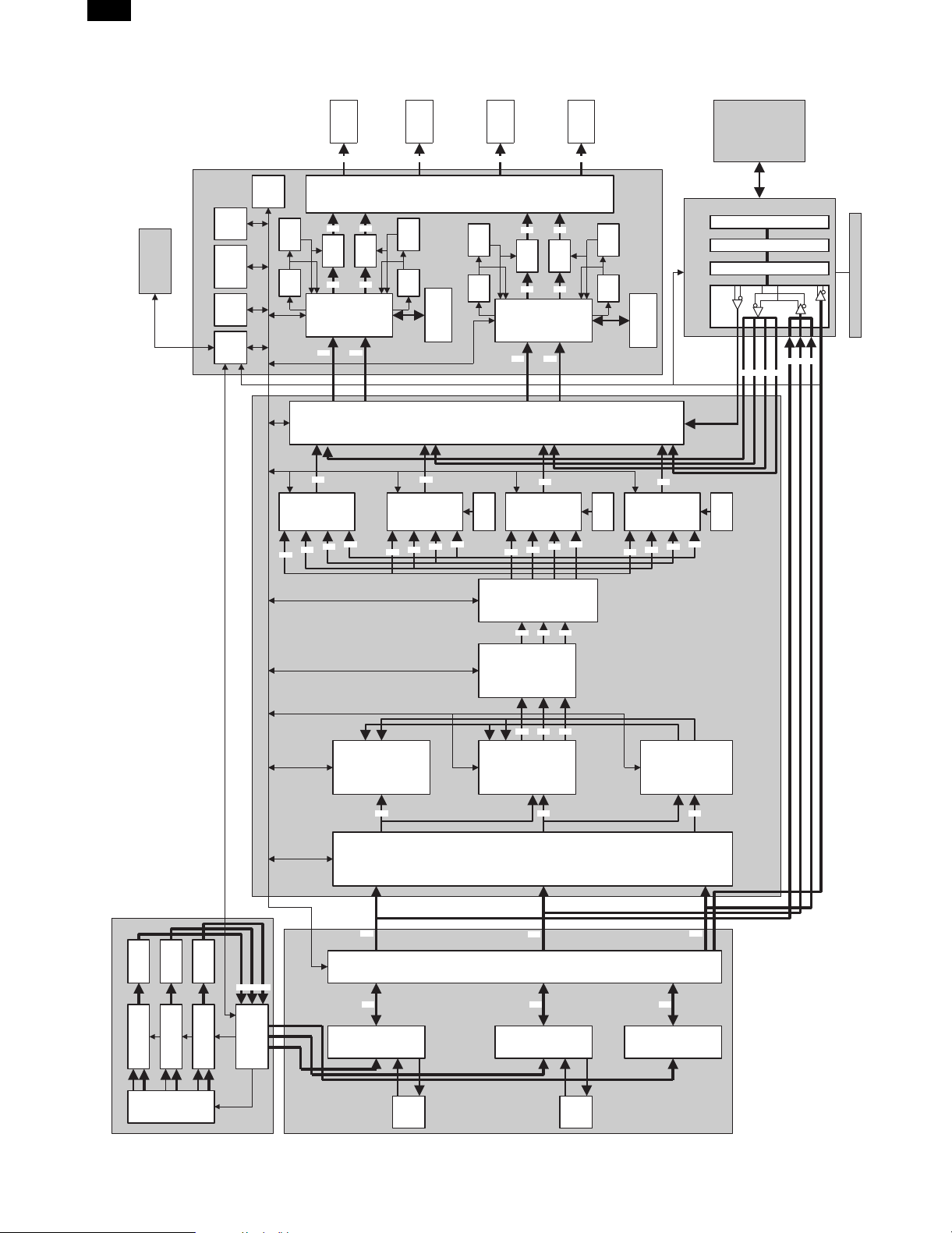
PCU PWB
Synchronous S10
64K*8
SRAM
EEPROM
CPU
ICU-MAIN PWB
CPUC
Synchronous S10
LSU K
LSU Y
LSU M
LSU C
AR-PE1
K
FROM
*4
Synchronous
K
VCO
K
K
ASIC
Y
PWM
PWMK
Y
LSU
ASIC
Y
Y
M
IC
K
Color
correction
C
K
Y
IC
Synchronous
VCO
Color
C
Tandem memory
Y
ASIC
correction
M
IC
Differential
Y
IC
Synchronous
VCO
adjustment
Intermediate
ROM
M
ASIC
C
C
M
PWM
PWM
C
M
LSU
ASIC
M
C
M
Color
ASIC
correction
M
C
K
IC
IC
Synchronous
Synchronous
Asynchronous S10
C
Color
ASIC
correction
M
C
AR-PX1/PX2
Printer connection kit
CRESET
Y
VCO
Tandem memory
ROM
Y
K
Printer controller
External connection cable
Connector PWB
Printer I/F PWB
Printer
I/F PWB
KYM
CCLK
ROM
C
WAKE UP signal
Operation control PWB
RGB
ECLK, HSYNC, SSYNC
R ADC
R analog IC
G ADC
G analog IC
B ADC
B analog IC
R
CCD ASIC
ICU-IMG PWB
B
G
RGB
Area
R
R
R SCN
ASIC
separation A
C
ASIC
C
ASIC
Area
separation C
C
Area
separation B
Input
VIF
Black
generation
M
M
ASIC
M
processing
G
G
G SCN
ASIC
ASIC
ASIC
Y
Y
Area
ASIC
separation D
Y
B
B
ASIC
B SCN
[3] BLOCK DIAGRAM
1.Overall block diagram
CCD PWB
Color
3-line
CCD
ICU-SCN PWB
FMEM
FMEM
– 9 –
Page 11

2. Engine (machine)-to-controller
connection
VSYNC - SSYNCB6
HSYNC - HSYNCB6
C/R Data[0 - 7] - BDC[0 - 7]
DR[0 - 7]
AR-PX1
M/G Data[0 - 7] - BDM[0 - 7]
Y/B Data[0 - 7] -
Controller
K Data[0 - 7] -
ECLK CCLK -
/ CONTRESET - /PRTC RES
/ CONTUP -(WAKE UP)
GND GND
/ ENGINEUP - /PRTE RDY
/CRDY /PRT RTS -
STATUS - PRT RXD
/SRDY -
PRT P
DG[0 - 7]
BDY[0 - 7]
DB[0 - 7]
Engine
Controller
BDK[0 - 7]BDK[0 - 7]
SCLKB6
BPCLK
/PRTC RDY
/PRT CTS
PRT TXD CMD PRT P
/PRT S /PRT S
SIGNAL LIST
SIGNAL NAME
CONTROLLER SIDE ENGINE(COPIER) SIDE
VSYNC - SSYNCB6
HSYNC - HSYNCB6
OUTPUT FUNCTION
Print mode Page Sync Signal
E
Scanner mode Page Sync Signal
Print mode Line Sync Signal
E
Scanner mode Line Sync Signal
This signal is always output during power-on.
C/R Data[0 - 7] - BDC[0 - 7] C Print mode 8 bit Cyan data
DR[0 - 7] E Scanner mode 8 bit Red data
M/G Data[0 - 7] - BDM[0 - 7] C Print mode 8 bit Magenta data
DG[0 - 7] E Scanner mode 8 bit Green data
Y/B Data[0 - 7] - BDY[0 - 7] C Print mode 8 bit Yellow data
DB[0 - 7] E Scanner mode 8 bit Blue data
K Data[0 - 7] - BDK[0 - 7] C Print mode 8 bit Black data
ECLK - SCLKB6
21MHz Clock supplied by the Engine. Data is accepted by the Controller at this CLK
transitions to true. This CLK sends to Engine as the CCLK. This ECLK is transmitted
E
from the Engine to the Controller. Then, ECLK is generated into CCLK at the
Controller and transmitted to the Engine. This signal is always output during
power-on.
CCLK BPCLK
21MHz Clock supplied by the Controller. Data is accepted by Engine at this CLK
C
transitions to true. This signal is always output during power-on.
/ CONTRESET - /PRTC RES E Reserve
/ CONTUP -(WAKE UP) /PRTC RDY C Indicates Controller power is up and it is able to communicate. Engine start signal
GND GND E/C Ground
/ ENGINEUP - /PRTE RDY E Indicates the Print Engine is up and ready to communicate. Controller start signal
CMD - PRT TXD
/CRDY /PRT RTS -
STATUS PRT RXD
/SRDY /PRT CTS
Serial channel signal used to send serial command information from the controller to
C
the engine.
Serial channel signal indicating whether the Engine is ready to receive status
E
information over the serial channel.
Serial channel signal that is used to send serial status information from the Engine
E
to the Controller.
Serial channel signal indicating whether the Controller is ready to receive status
C
information over the serial channel.
PRT P PRT P E Operation mode switch signal (Printer operation mode)
/PRT S /PRT S E Operation mode switch signal (Scanner operation mode)
E: Engine
C: Controller
– 10 –
Page 12

AR-PX1
Page 13

PARTS GUIDE
PRINTER I/F KIT
AR-PX1
MODEL AR-PX2
AR-PX1
AR-PX2
For North and
(
South America
)
CONTENTS
1 Packing material & Accessories
2 Printer I/F PWB unit
■ Index
SHARP CORPORATION
This document has been published to be
used for after sales service only.
The contents are subject to change without
notice.
Page 14

AR-PX1
AR-PX2
DEFINITION
The definition of each Rank is as follows and also noted in the lis t
A : Parts necessary to be stocked as High usage parts.
B : Parts necessary to be stocked as Standard usage parts.
C : Low usage parts.
D : Parts necessary for refurbish.
E : Unit parts recommended to be stocked for efficient after sales service.
Please note that the lead time for the said parts may be longer than normal parts.
S : Consumable parts.
Please note that the following parts used in Copier under the same description are classi fied into A or B Rank depending
upon the place used.
Example : Gear made of Metal, Sprocket, Beari ng, Belt made of Rubber, Spring clutch mechanism.
A Rank : The parts which may be with the revolution or loading.
B Rank : Parts similar to A Rank parts, but are not included in Rank A.
Because parts marked with "!" is indispensable for the machine safety maintenance and operati on, it must be replaced with
the parts specific to the product specification.
F Other than thi s Parts Guide, please refer to documents Service Manual (including Circuit Diagram) of this model.
F Pl ease use the 13 digit code described in the right hand corner of front cover of the document, when you place an order.
F For U.S. onl y-Use order codes provided in advertising literature. Do not order from parts department.
1 Packing material & Accessories
PRICE
NO. PARTS CODE
SPAKA6077FCZZ AH
1
SSAKA3440QCZZ AB
2
QCNW-0164FCZZ BX
3
SPAKC6076FC13 AN
SPAKC6076FCZZ AN
4
SPAKC6076FC12 AN
SPAKC6076FC11 AN
SPAKA0011YSZZ AD
5
CPLTM5607FC51 BD
6
CPWBN1384FC51 BD
7
CPWBN1382FC51 CD
8
SSAKA1241QCZZ AB
9
SPAKP2374ACZZ AD
10
SSAKA5003CCZZ AA
11
SSAKH3012CCZZ AA
12
QCNW-0163FCZZ BN
13
LHLDW1435FCZZ AF
14
DHAI-3131FCZZ AG
15
XBPSD30P06XS0 AA
101
TLABS3760FCZZ AC
102
TLABZ4173FCZZ AG
103
RANK
NEW
MARK
N D Spacer
N C Twist cable
N D Packing case (USA)
N D Packing case (Japan)
N D Packing case (Europe,U.Kingdom,Australia,New Zealand)
N D Packing case (Canada,other countries)
N D Protect sheet
N E Printer CN fixing plate U
N E Printer CN PWB unit
N E Printer I/F PWB unit
N C Flat cable
N C Flat cable holder
N C Wake up harness
PART
RANK
D Vinyl bag (300
D Vinyl bag (240
D Vinyl bag (240
D Vinyl bag (140
D Vinyl bag (80
CScrew (3
D CE mark label (Europe,U.Kingdom,Australia,New Zealand)
D Connector caution label (Europe,U.Kingdom,Australia,New Zealand)
´420mm)
´180mm)
´170mm)
´260mm)
´120mm)
´6XS)
DESCRIPTION
– 1 –
Page 15

1 Packing material & Accessories
15
AR-PX1
AR-PX2
11
12
14
1
13
2
10
3
9
8
6
7
4
5
5
2 Printer I/F PWB unit
NO. PARTS CODE
QCNCM1054FCZZ AS
1
QCNCM7014SC0C AA
2
QCNCW1053FCZZ AM
3
RFILN0041FCZZ AC
4
VCEAGA1AW107M AB
5
VCEAGU1AW476M AA
6
VCEAGA1AW477M AB
7
VCKYCY1EF104Z AA
8
VCKYCY1HB561K AA
9
VCKYCY1HF223Z AA
10
VHDDSS133//-1 AA
11
VHIDS90LV018A AQ
12
VHIDS90LV031A AY
13
VHIDS90LV032A AY
14
VHINJU7200L33 AF
15
VHI74LCX32MTC AE
16
VHI74LV32AT// AD
17
VHI74VHC32MTC AD
18
VRS-TS2AD101J AA
19
VRS-TS2AD101J AA
VRS-TS2AD103J AA
20
VRS-TS2AD361J AA
21
VRS-TS2AD681J AA
22
VSDTC114EK/-1 AB
23
(Unit)
CPWBN1382FC51 CD
901
PRICE
RANK
FCP04110
NEW
PART
MARK
RANK
N C Connector (100pin) [CN543]
C Connector (3pin) [CN542]
N C Connector (80pin) [CN541]
C EMI filter (ZJSR5101222) [NF100,102]
C Capacitor (10WV 100mF) [C146]
C Capacitor (10WV 47mF) [C143]
C Capacitor (10WV 470mF) [C108,125,137]
Capacitor (25WV 0.10mF)
C
C Capacitor (50WV 560PF) [C114]
C Capacitor (50WV 0.022mF) [C144,145]
B Diode (DSS133) [D100]
N B IC (DS90LV018A) [IC110]
N B IC (DS90LV031A) [IC104,106~109,122,123,125]
N B IC (DS90LV032A) [IC100~103,112~115,124]
N B IC (NJU7200L33) [IC127]
B IC (74LCX32MTC) [IC105,116~121]
B IC (74LV32AT) [IC126]
B IC (74VHC32MTC) [IC111]
Resistor (1/10W 100W
C
C Resistor (1/10W 100W
C Resistor (1/10W 10KW
C Resistor (1/10W 360W
C Resistor (1/10W 680W
B Transistor (DTC114EK) [Q100]
N E Printer I/F PWB unit
±5%)
±5%) [R145,146,148,149,151,152,154,155,156,161,162]
±5%) [R110,113,116,119,122,144,147,150,153,157,160]
±5%) [R121]
±5%) [R120]
DESCRIPTION
[C100~105,117~122,127~136,138~142]
[R100~109,111,112,114,115,117,118,128,136~143]
– 2 –
Page 16

AR-PX1
AR-PX2
■ Index
PARTS CODE NO.
[C]
CPLTM5607FC51
CPWBN1382FC51
"
CPWBN1384FC51
[D]
DHAI-3131FCZZ
[L]
LHLDW1435FCZZ
[Q]
QCNCM1054FCZZ
QCNCM7014SC0C
QCNCW1053FCZZ
QCNW-0163FCZZ
QCNW-0164FCZZ
[R]
RFILN0041FCZZ
[S]
SPAKA0011YSZZ
SPAKA6077FCZZ
SPAKC6076FC11
SPAKC6076FC12
SPAKC6076FC13
SPAKC6076FCZZ
SPAKP2374ACZZ
SSAKA1241QCZZ
SSAKA3440QCZZ
SSAKA5003CCZZ
SSAKH3012CCZZ
[T]
TLABS3760FCZZ
TLABZ4173FCZZ
[V]
VCEAGA1AW107M
VCEAGA1AW477M
VCEAGU1AW476M
VCKYCY1EF104Z
VCKYCY1HB561K
VCKYCY1HF223Z
VHDDSS133//-1
VHI74LCX32MTC
VHI74LV32AT//
VHI74VHC32MTC
VHIDS90LV018A
VHIDS90LV031A
VHIDS90LV032A
VHINJU7200L33
VRS-TS2AD101J
VRS-TS2AD103J
VRS-TS2AD361J
VRS-TS2AD681J
VSDTC114EK/-1
[X]
XBPSD30P06XS0
1- 6
1- 8
2-901
1- 7
1- 15
1- 14
2- 1
2- 2
2- 3
1- 13
1- 3
2- 4
1- 5
1- 1
1- 4
1- 4
1- 4
1- 4
1- 10
1- 9
1- 2
1- 11
1- 12
1-102
1-103
2- 5
2- 7
2- 6
2- 8
2- 9
2- 10
2- 11
2- 16
2- 17
2- 18
2- 12
2- 13
2- 14
2- 15
2- 19
2- 20
2- 21
2- 22
2- 23
1-101
PRICE
RANK
BD
CD
CD
BD
AG
AF
AS
AA
AM
BN
BX
AC
AD
AH
AN
AN
AN
AN
AD
AB
AB
AA
AA
AC
AG
AB
AB
AA
AA
AA
AA
AA
AE
AD
AD
AQ
AY
AY
AF
AA
AA
AA
AA
AB
AA
NEW
PART
MARK
RANK
NE
NE
NE
NE
NC
NC
NC
C
NC
NC
NC
C
ND
ND
ND
ND
ND
ND
D
D
D
D
D
D
D
C
C
C
C
C
C
B
B
B
B
NB
NB
NB
NB
C
C
C
C
B
C
PARTS CODE NO.
PRICE
RANK
NEW
MARK
PART
RANK
– 3 –
Page 17

CAUTION FOR BATTERY REPLACEMENT
(Danish) ADVARSEL !
Lithiumbatteri – Eksplosionsfare ved fejlagtig håndtering.
Udskiftning må kun ske med batteri
af samme fabrikat og type.
Levér det brugte batteri tilbage til leverandoren.
(English) Caution !
Danger of explosion if battery is incorrectly replaced.
Replace only with the same or equivalent type
recommended by the manufacturer.
Dispose of used batteries according to manufacturer’s instructions.
(Finnish) VAROITUS
Paristo voi räjähtää, jos se on virheellisesti asennettu.
Vaihda paristo ainoastaan laitevalmistajan suosittelemaan
tyyppiin. Hävitä käytetty paristo valmistajan ohjeiden
mukaisesti.
(French) ATTENTION
Il y a danger d’explosion s’ il y a remplacement incorrect
de la batterie. Remplacer uniquement avec une batterie du
même type ou d’un type équivalent recommandé par
le constructeur.
Mettre au rebut les batteries usagées conformément aux
instructions du fabricant.
(Swedish) VARNING
Explosionsfara vid felaktigt batteribyte.
Använd samma batterityp eller en ekvivalent
typ som rekommenderas av apparattillverkaren.
Kassera använt batteri enligt fabrikantens
instruktion.
AR-PX1
Page 18

AR-PX1
All rights reserved.
Printed in Japan.
No part of this publication may be reproduced,
stored in a retrieval system, or transmitted,
in any form or by any means,
electronic; mechanical; photocopying; recording or otherwise
without prior written permission of the publisher.
SHARP CORPORATION
Digital Document Systems Group
Quality & Reliability Control Center
Yamatokoriyama, Nara 639-1186, Japan
1999 December Printed in Japan
 Loading...