

Page 1

SERVICE MANUAL
CODE: 00ZARPX3//A1E
PRINTER I/F KIT
AR-PE2
AR-PX3
MODEL
CONTENTS
[1] OUTLINE . . . . . . . . . . . . . . . . . . . . . . . . . . . . . . . . . . . . . . . . . . . . . . .1
[2] SETUP. . . . . . . . . . . . . . . . . . . . . . . . . . . . . . . . . . . . . . . . . . . . . . . . .1
PARTS GUIDE
AR-PX4
Parts marked with “ ” are important for maintaining the safety of the set. Be sure to replace these parts with
specified ones for maintaining the safety and performance of the set.
This document has been published to be used
SHARP CORPORATION
for after sales service only.
The contents are subject to change without notice.
Page 2
AR-PE2/PX3/PX4 Installation Manual
SEE SHARP COPIER INSTALLATION MANUAL TO DETERMINE SUITABILITY.
FOR USE WITH COMPATIBLE SHARP COPIERS.
[1] OUTLINE
This unit is used to connect the printer controller with the scanner and
the printer section in the AR-C160.
1. Unit composition
This unit is composed of the following major parts:
AR-PE2
• Controller
• I/F card
• Connection cable
AR-PX3/PX4
• Power supply unit
2. Outline of operations
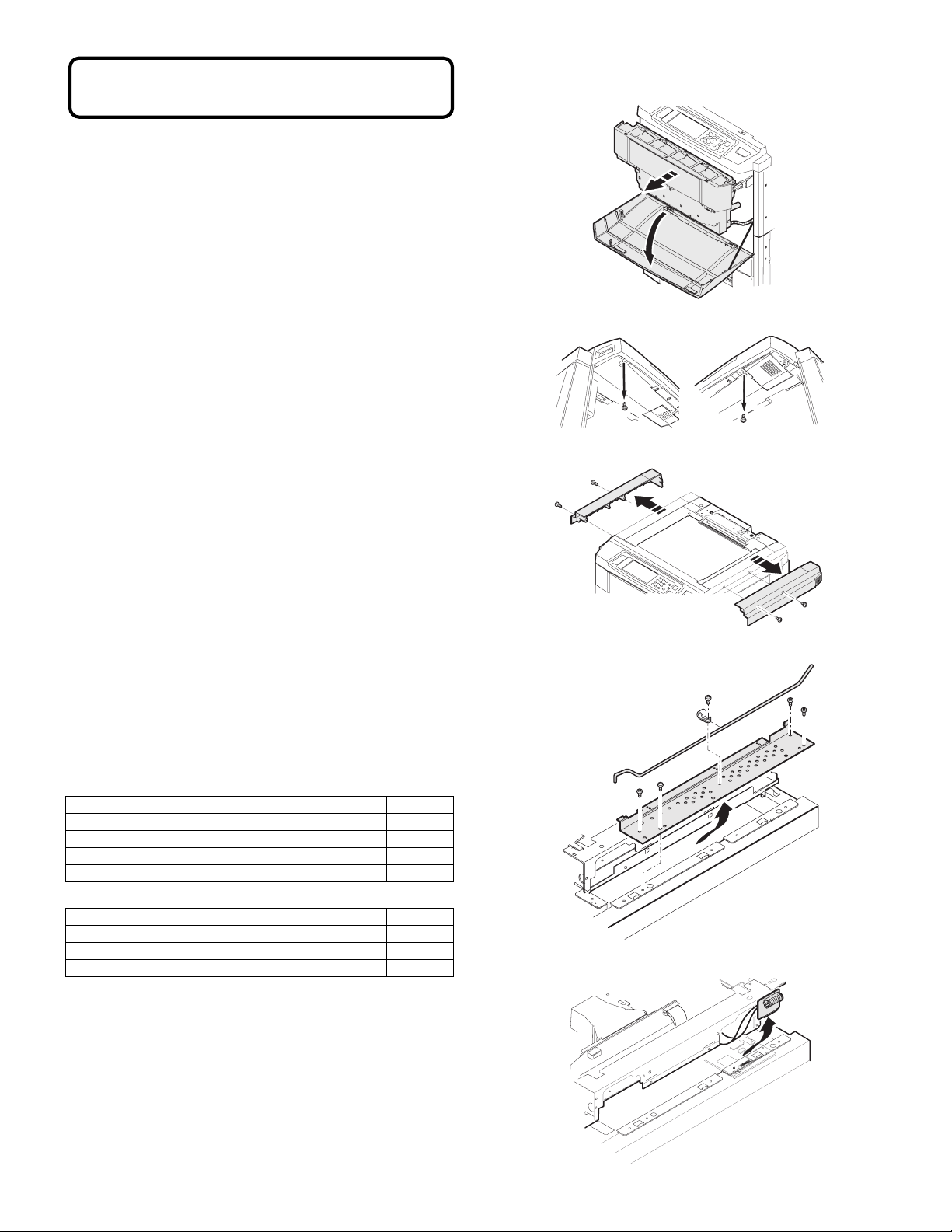
2. Parts assembly
1) Remove the operation unit.
Left side Right side
(Printer mode)
Each color image data of 8bit of Y/M/C/K outputted from the print controller.
(Scanner mode)
Each color image data of R/G/B scanned by the scanner is inputted to
the printer I/F card.
(Circuit system)
High-speed data transmission/reception is performed between the engine and the print controller.
[2] SETUP
Necessary tools: Screwdriver
1. Unpacking
(Parts list)
AR-PE2
No. Part name Quantity
1 Controller 1
2 I/F card 1
3 Flat cable 1
4 Wake up harness 1
AR-PX3/PX4
No. Part name Quantity
1 P ower supply unit 1
2 Screw (M4) 8
3 Caution label (Only EU) 1
2) Remove the left and right upper cabinet.
3) Remove the ICU PWB shield plate.
4) Remove the CCD flat cable connector.
– 1 –
Page 3
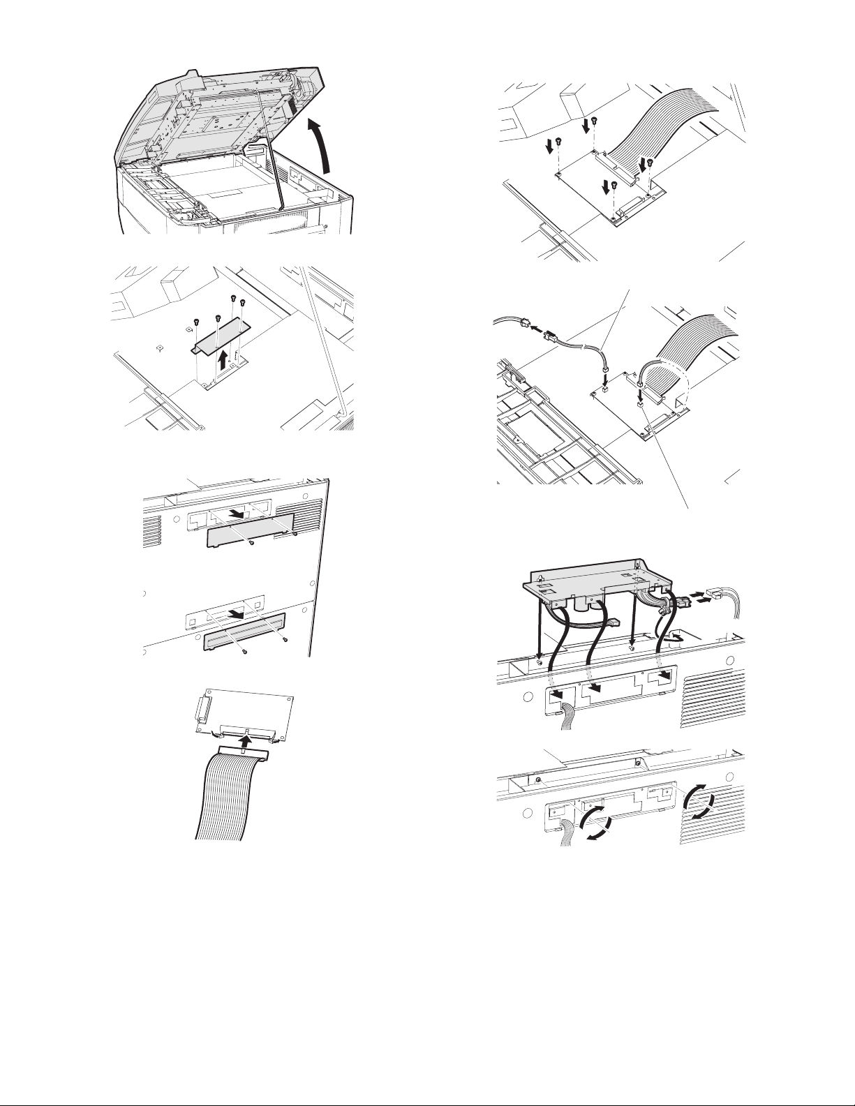
5) Open the scanner (reading) unit and fix it with the hold shaft.
6) Remove the interface cabinet.
7) Remove the cover plate on rear cabinet.
Removed screw is used for attach the printer I/F card.
9) Attach the printer I/F card with the accessory screw, and connect
the wake up signal harness and clock harness.
Wake up signal harness
8) Connect engine side I/F cable.
Clock harness
10) Attach the printer power supply unit, and connect printer PS cable.
– 2 –
Page 4

11) Remove the top cover of the printer controller and attach the
printer controller.
13) Attach the top cover of the printer controller.
14) Install all the parts that were removed to their original positions.
15) Attach the caution label to the cabinet. (Only EU version)
12) Connect controller side I/F cable and DC cable.
3. Setting
1) Turn on the power of the unit.
2) Enter the simulation 26-1 mode.
3) Press "PRN: AR-PE2" button. (Communication between the unit
and the printer controller is allowed.)
4) Cancel the simulation mode.
– 3 –
Page 5

PARTS GUIDE
1 電源ユニット (Power supply unit)
NO. PARTS CODE
XBPSD30P16000
1
! RDENC0009FCZZ
2
! RDENC0010FCZZ
DHAI-3325FC11
3
DHAI-3321FC11
4
PSPAZ0382FCZZ
5
XBPSD30P08K00
6
LBNDJ0013FCZ1
7
LSUPP0109FCZZ
8
LPLTM5950FCZZ
9
CPWBN1512FC51
10
CPWBN1512FC52
LSUPP0086FCZZ
11
JAPAN ONLY
ORDER CODE
541 970 1103 AA DD C
578 685 0519 BL HL N E
578 685 0520 BS MJ N E
572 542 2055 AN EG N C
572 542 2054 AM EG N C
572 413 0295 AA DD C
541 970 0014 AA DD C
572 201 0118 AA DJ C
572 233 0127 AC DJ C
578 221 0686 AN EG N C
572 684 3841 BK HC N E
572 684 3842 BL HG N E
572 233 0116 AB DJ C
1 電源ユニット (Power supply unit)
PRICE RANK
Ex. Ja.
NEW
MARK
PART
RANK
DESCRIPTION
Screw (3×16)
Power supply PWB (100V Series)
Power supply PWB (200V Series)
PRT power supply harness PRT
DC harness DC
Spacer for BCL (100V Series) BCL
Screw (3×8S)
Band
Spacer
PRT power supply fixing plate PRT
PRT power supply relay PWB (100V Series) PRT
PRT power supply relay PWB (200V Series) PRT
Supporter (LCBS-6)
ビス
電源基板
電源基板
電源ハーネス
ハーネス
ヨウスペーサー
ビス
バンド
スペーサー
電源押えプレート
デンゲンリレー基板
デンゲンリレー基板
サポーター
4
7
1
2
E
F
F
E
5
6
D
8
F
E
D
8
2 梱包 & 付属品(Packing Material & Accessories)
NO. PARTS CODE
SPAKA6200FCZZ
1
SPAKA399ACCZZ
2
SSAKA0006UCZZ
3
XHBSD40P08000
4
XBBSE40P10000
5
TLABZ4173FCZZ
6
SPAKA6199FCZZ
7
SPAKC6198FCZZ
SPAKC6198FC11
8
SPAKC6198FC12
JAPAN ONLY
ORDER CODE
578 902 0308 AE DS N D
505 902 5004 AB DD D
541 906 1016 AA DD D
578 970 0074 AA DD C
572 970 0641 AA DD C
572 917 3365 AG DX D
578 902 0307 AL EB N D
578 901 0544 AM EG N D
578 901 0545 AM EG N D
578 901 0546 AM EG N D
PRICE RANK
Ex. Ja.
NEW
MARK
PART
RANK
3
200V Series
D
2
6
9
6
B
C
A
10
C
B
B
A
11
FCP04931
A
C
11
12
DESCRIPTION
Spacer B
Vinyl bag
Vinyl bag (50×60)
Screw (4×8)
Screw (4×10)
Caution label (Europe,U.kingdom,Australia,Newzealand)
Spacer A
Packing case (JAPAN)
Packing case (U.S.A/CANADA)
Packing case (Other countries)
10
スペーサー
B
ポリ袋
ポリ袋
ビス
ビス
注意ラベル
スペーサー
A
パッキングケース
パッキングケース
パッキングケース
2 梱包 & 付属品(Packing Material & Accessories)
1
2
4
5
6
3
7
8
FCP04932
Page 6

Page 7

Page 8

All rights reserved.
Printed.
No part of this publication may be reproduced,
stored in a retrieval system, or transmitted,
in any form or by any means,
electronic; mechanical; photocopying; recording or otherwise
without prior written permission of the publisher.
Trademark Acknowledgments
Microsoft Windows, MS-DOS, Windows NT, Windows 2000 are trademarks of Microsoft
Corporation in the U. S. A. and other countries.
Macintosh, Power Macintosh, Mac OS, LaserWriter, and AppleTalk are registered trademarks of
Apple Computer, Inc.
IBM, PC/ AT, and PowerPC are trademarks of International Business Machines Corporation.
Pentium is a registered trademark of Intel Corporation.
PCL is a trademark of the Hewlett- Packard Company.
PostScript is a registered trademark of Adobe Systems Incorporated.
NetWare is a registered trademark of Novell, Inc.
All other trademarks and copyrights are the property of their respective owners.
Digital Document Systems Group
Quality & Reliability Control Center
Yamatokoriyama, Nara 63 9-11 86, Ja pan
2001 June Printed
 Loading...