

Page 1
AR-PA1
CODE: 00ZARPA1//A1E
DIGITAL COPIER
OPTION
LCD PANEL KIT
MODEL AR-PA1
CONTENTS
[ 1 ] PRODUCT OUTLINE . . . . . . . . . . . . . . . . . . . . . . . . . . . . . . . . . . 1-1
[ 2 ] SYSTEM DIAGRAM . . . . . . . . . . . . . . . . . . . . . . . . . . . . . . . . . . . 1-1
[ 3 ] SPECIFICATIONS . . . . . . . . . . . . . . . . . . . . . . . . . . . . . . . . . . . . 1-1
[ 4 ] UNPACKING AND INSTALLATION . . . . . . . . . . . . . . . . . . . . . . . 1-1
Parts marked with “ ” is important for maintaining the safety of the set. Be sure to replace these parts with specified ones
for maintaining the safety and performance of the set.
This document has been published to be used
SHARP CORPORATION
for after sales service only.
The contents are subject to change without notice.
Page 2
AR-PA1
[1] PRODUCT OUTLINE
This machine is installed to the digital copier which has no functions of FAX and printer, and is used to display the status. It is nor required for
models which have functions of FAX and printer.
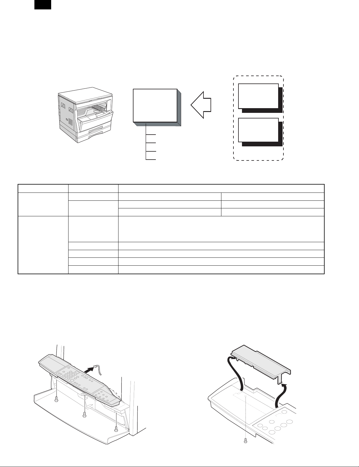
[2] SYSTEM DIAGRAM
Printer kit
LCD panel kit
(AR-PA1)
(PCL)
LCD unit
Mother board
Digital copier
PWB attachment frame
etc.
[3] SPECIFICATIONS
LCD digits 20 digits × 2 Display of status/parameter of printer/FAX*
Data ON when data supplied. Common to printer/FAX
LED display
Keys
* For details, refer to the printer kit/FAX kit Service Manual.
On-line
Changes between the on-line and off-line modes.
Line
Menu Used to show setting menus on the display in sequence.∗
← → Used to change the value of any item.∗
Enter Used to enter a new value.
Item Used to show the setting items of the selected menu in sequence.∗
When the printer is on-line, it can receive data from the computer with which it is connected.
When the printer is off-line, you can use operation panel keys to make print settings.
Note, however, that you cannot make settings if the "Data Remaining" message is displayed.
ON in on-line
OFF in off-line
[4] UNPACKING AND INSTALLATION
FAX kit
Options
1. Procedures on the copier (operation panel)
A. Copier operation panel disassembly
• Remove three screws and one connector, and remove the
operation panel.
1 – 1
B. Cover disassembly
• Remove one screw and disengage two pawls, and remove the
cover.
Page 3

AR-PA1
C. Printer operation panel installation
• Engage two pawls and fix the printer operation panel with one
screw.
Then connect the flat cable to the connector.
2. Procedures on the copier (rear side)
A. Copier rear cabinet disassembly
• Remove seven screws and remove the rear cabinet.
C. PWB fixing plate installation
• Fix the plate with four screws.
D. Printer PWB or Fax PWB installation
• Refer to the Rach service manual.
E. Mother board installation
• Insert the connectors and fix them, then connect the connec-
tors of the copier to them.
B. Copier shield plate disassembly
• Remove six screws, and remove the shield plate.
F. Shield plate installation
• Fix the shield plate with six screws.
G. PWB cover installation
• Install the PWB cover with 14 screws.
1 – 2
Page 4

AR-PA1
COPYRIGHT © 1999 BY SHARP CORPORATION
All rights reserved.
Printed in Japan.
No part of this publication may be reproduced,
stored in a retrieval system, or transmitted,
in any form or by any means,
electronic, mechanical, photocopying, recording, or otherwise,
without prior written permission of the publisher.
SHARP CORPORATION
Printing & Reprographic Systems Group
Quality & Reliability Control Center
Yamatokoriyama, Nara 639-1186, Japan
1999 February Printed in Japan N
 Loading...