

Page 1
SERVICE MANUAL
CODE: 00ZARP21//A1E
DIGITAL MULTIFUNCTIONAL
SYSTEM OPTIONS
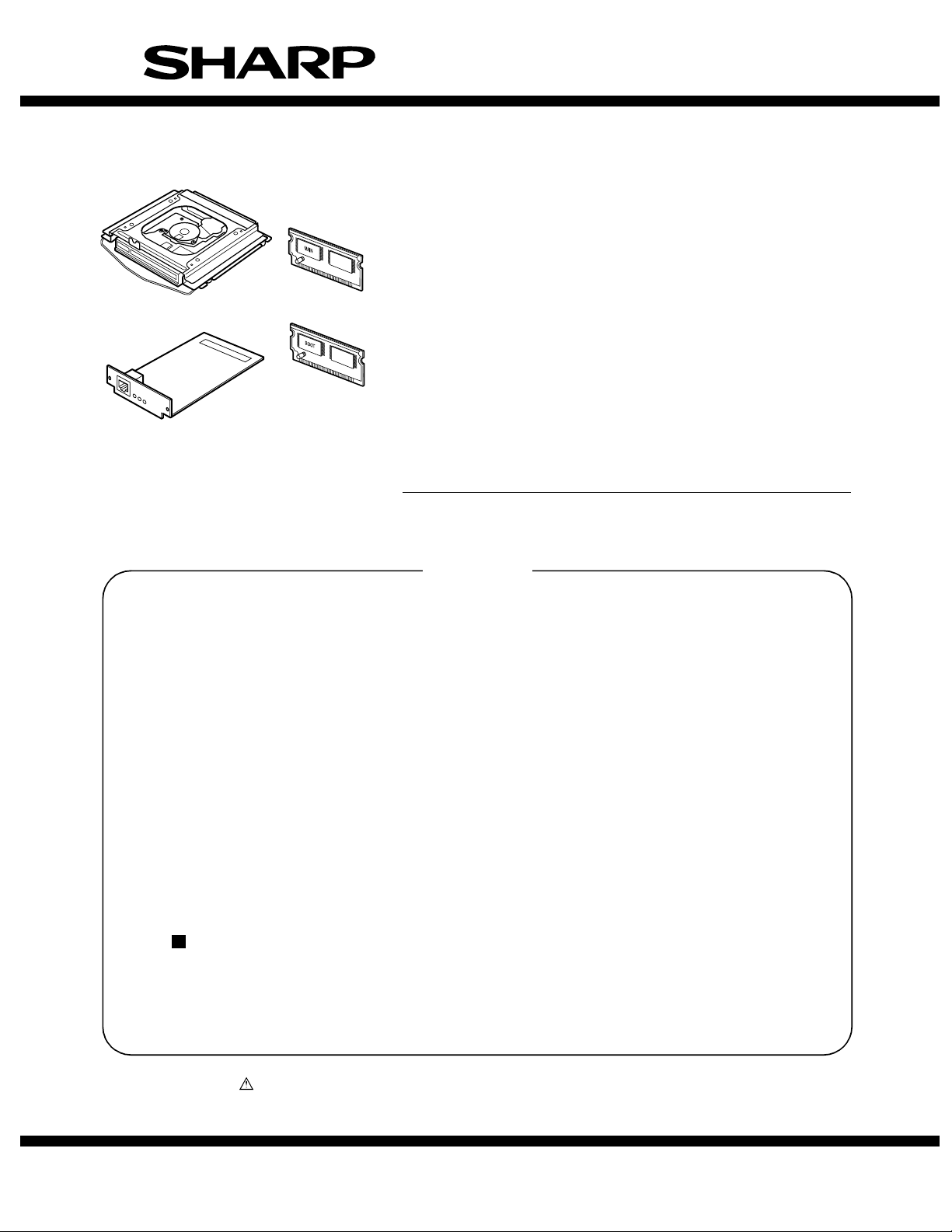
PRINTER EXPANSION KIT/
PRINT SERVER CARD
AR-P20/P21
MODEL
CONTENTS
[1] CONFIGURATION . . . . . . . . . . . . . . . . . . . . . . . . . . . . . . . . . . . . . . 1-1
[2] SPECIFICATIONS . . . . . . . . . . . . . . . . . . . . . . . . . . . . . . . . . . . . . . 2-1
[3] INSTALLATION . . . . . . . . . . . . . . . . . . . . . . . . . . . . . . . . . . . . . . . . 3-1
[4] CONFIGURATION REPORT (TEST PAGE) . . . . . . . . . . . . . . . . . . 4-1
[5] SETTING . . . . . . . . . . . . . . . . . . . . . . . . . . . . . . . . . . . . . . . . . . . . . 5-1
[6] SIMULATION . . . . . . . . . . . . . . . . . . . . . . . . . . . . . . . . . . . . . . . . . . 6-1
[7]
ELECTRICAL SECTION . . . . . . . . . . . . . . . . . . . . . . . . . . . . . . . . . 7-1
AR-NC7/NC8
Parts guide
Parts marked with “ ” are important for maintaining the safety of the set. Be sure to replace these parts with
specified ones for maintaining the safety and performance of the set.
This document has been published to be used
SHARP CORPORATION
for after sales service only.
The contents are subject to change without notice.
Page 2
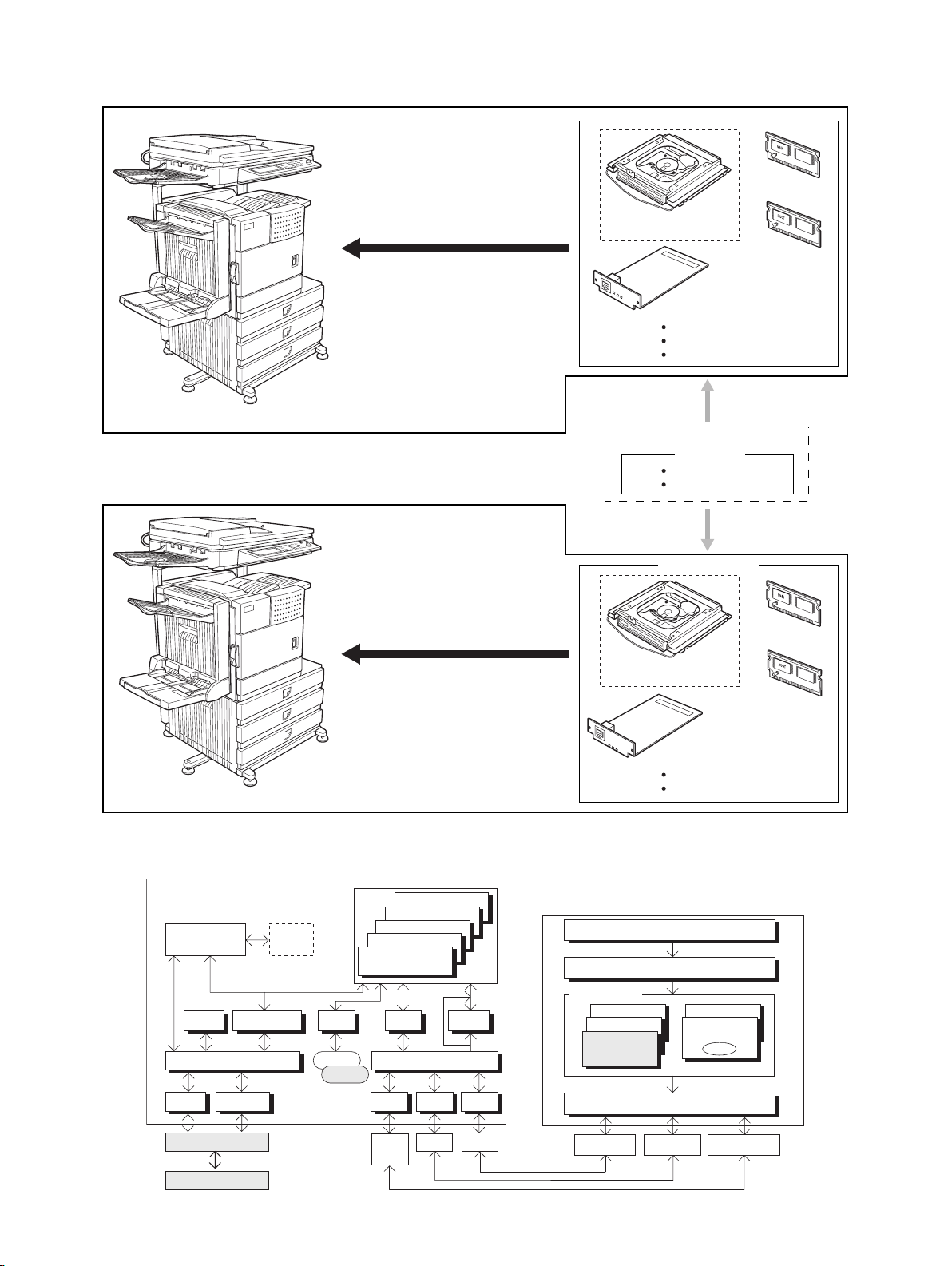
[1] CONFIGURATION
North America
<AR-M355U/M455U>
Except for North America
Network printer function: AR-P20
Network printer and
Document filing function: AR-P21
<AR-P20/P21>
MAIN ROM
HDD expansion PWB
(AR-P21 only)
BOOT ROM
Print server card
Printer utility CD-ROM
Network utility CD-ROM
Product key sheet
Option (PS3 expansion kit)
<AR-PK6>
CD-ROM
Product key sheet
<AR-M351U/M451U>
Printer software, firmware diagram
File Manager
Engine I/F Manager
Memory
Print Manager
Roman
Kanji
Network function: AR-NC7
Network and
Document filing function: AR-NC8
Firmware
TIFF
PDF
PostScript
PCL6(SPDL2)
PCL5e(SPDL)
PJLFontStatus
Host I/O Manager
AUTO
<AR-NC7/NC8>
MAIN ROM
HDD expansion PWB
(AR-NC8 only)
BOOT ROM
Print server card
Network utility CD-ROM
Product key sheet
Win95/Win98/WinMe/WinNT4.0/Win2K/WinXP
Application
GDI(Graphic Module)
Printer Driver
PostScript
PCL5e(SPDL)
PCL6(SPDL2)
Others
Adobe
PostScript
PPD
Serial
ImageBus
PCU
Engine
PCI
USB 1284
1284
USB
Soft
NIC
1284 Port Ethernet Port
AR-P20/P21, AR-NC7/NC8 CONFIGURATION 1 - 1
Print Spooler
USB Port
Page 3
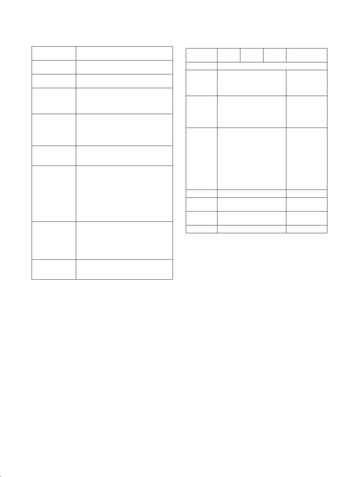
[2] SPECIFICATIONS
1. Printer specifications
Memory capacity
(standard)
DIMM slots for
additional memory
Page description
language
Resident font For PCL: Outline fonts: 80
Interface IEEE-1284 compatible parallel interface
LAN connection 10Base-T/100Base-TX
Operating system IBM PC/AT or compatible computer:
Continuous print
speed
Resolution Data processing: 600 x 600 dpi
* An optional PS3 expansion kit is needed.
Standard 128MB
One (128 MB to 256 MB memory can be
mounted.)
PCL6, PCL5e, PS3 emulation*
Barcode fonts (option): 28
Bitmap font: 1
PostScript compatible fonts (option): 136
(P1284B connector)
USB1.1 (Windows98/ME/2000/XP/
Server 2003)
USB2.0 (Windows2000/XP/Server 2003)
Supported protocols:
IPX/SPX, TCP/IP, EtherTalk, NetBEUI
Windows 95/98/Me,
Windows NT 4.0 (ServicePack5 or later),
Windows 2000 Server/Professional,
Windows XP Professional/Home Edition,
Windows Server 2003
Macintosh series*: Mac OS 8.6 to 9.2.2,
10.1.5, and 10.2 to 10.2.8 (except 10.2.2),
10.3 to 10.3.3
Same as the engine speed of the machine
(Print speed during printing of the second
sheet and following sheets when using A4
(8-1/2" x 11") plain paper and performing
continuous one-sided printing of the same
page; excluding use of offset output.)
Printing: 600 x 600 dpi,
1200 dpi equivalent x 600 dpi
2. Printer driver functions
(1) Windows driver functions
a. General
Function PCL5e PCL6 PS
Copies 1-999
Orientation Portrait
Landscape
Duplex 1-sided
2-sided
(Left /top/ right
binding)
Booklet Invoice on Letter
Letter on Ledger
A5 on A4
A4 on A3
B5 on B4
Letter on Letter
Ledger on Ledger
A4 on A4
A3 on A3
B4 on B4
Binding edge Left / top / right No
N-up 2/4/6/8/9/16 2 / 4 / 6 / 9 / 16
N-up order Z / Reversed Z /
N / Reversed N
N-up border Yes / No Always Yes (*2)
*1: For printing, PS driver bundled with the Windows is required.
*2: Since the function is of PS driver bundled with Windows, spec-
ification may vary according to the OS.
PPD file *1
(for Windows XP)
Portrait
Landscape-A
Landscape-B
(*2)
1-sided
2-sided
(Long / short
binding)
(*2)
Yes
(2up booklet only)
(*2)
(*2)
Z (*2)
AR-P20/P21, AR-NC7/NC8 SPECIFICATIONS 2 - 1
Page 4
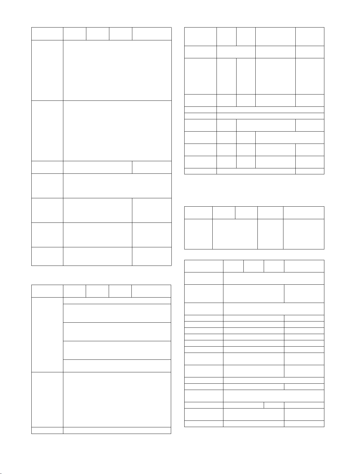
b. Paper Input
Function PCL5e PCL6 PS
Paper size A3 / B4 / A4 / B5 /
Paper type Plain
Custom
paper type
Source
selection
Cover Yes/No
Insert page Yes/No
Transparency
inserts
*1: For printing, PS driver bundled with the Windows is required.
c. Paper Output
Function PCL5e PCL6 PS
Output tray
selection
Staple Finisher
Offset cancel Yes/No
*1: For printing, PS driver bundled with the Windows is required.
A5 / Ledger /
Legal / Foolscap /
Letter / Executive
/Invoice/8k / 16k
/COM10/C5/
Monarch/DL
ISO B5 /
Japanese post card /
Custom
Letter Head
Pre-Print
Pre-Punch
Recycle
Color
Label
Heavy Paper
Transparency
Envelope
7 type No
Automatic
Tray 1/2/3/4
Bypass-tray
LCT
User can select from
1-sided/2-sided/
No print
User can select from
1-sided/2-sided/
No print
No
Yes (Blank)
Yes (Printed)
Center tray
Finisher
• Top tray
• Offset tray
Saddle Stitch
Finisher
• Offset tray
Mailbin stacker
• Mailbin top tray
• Mailbin (1-7)
Duplex module
• Left tray
• No staple
• 1 staple
• 2 staples
Saddle Stitch
Finisher
• No staple
• 1 staple
• 2 staples
PPD file *1
(for Windows XP)
No
No
No
PPD file *1
(for Windows XP)
Saddle Stitch
Finisher
• No staple
• 1 staple
• 2 staples
d. Graphic
Function PCL5e PCL6 PS
Resolution
setting
Halftone
setting
Graphics
mode
Smoothing Yes/No
Toner save Yes / No
Photo
enhancement
Negative
image
Mirror image No No Horizontal
Zoom No No 25-400%
Fit to page Yes / No No
*1: For printing, PS driver bundled with the Windows is required.
*2: Since the function is of PS driver bundled with Windows, spec-
ification may vary according to the OS.
e. Font
Function PCL5e PCL6 PS
Download
font
f. Others
Function PCL5e PCL6 PS
Configuration
setting
Watermark Yes Yes
Line width
setting
Form overlay Yes No
Print hold Yes No
Confidential print Yes No
Sample print Yes No
Print accounting Yes No
Quick sets Yes No
Auto
configuration
Job end
notification
Tandem print Yes
Carbon print Yes No
Multienlargement
XY zoom No Yes No
Cover insert +
pamphlet
Document filing Yes No
*1: For printing, PS driver bundled with the Windows is required.
*2: Since the function is of PS driver bundled with Windows, spec-
ification may vary according to the OS.
600/300 dpi 600dpi 600dpi
No No Screen frequency
Raster
HP-GL2
Bitmap
TrueType
Raster
Vector
No Yes/No No
No No Yes / No
8.0 to 360.0
in 0.1 steps
Screen angle
0.0 to 360.0
in 0.1 steps
No No
Vertical
(XY zoom)
Bitmap
Type1
TrueType
Yes
No
Yes No
Yes No
No
Yes No
PPD file *1
(for Windows
XP)
No
Horizontal
(*2)
1-1000%
(*2)
PPD file *1
(for Windows XP)
Auto
Outline
Bitmap
Native TrueType
(*2)
PPD file *1
(for Windows XP)
(functionality is
limited)
AR-P20/P21, AR-NC7/NC8 SPECIFICATIONS 2 - 2
Page 5
(2) Macintosh driver functions
a. General
Function
Copies 1-999
Orientation Portrait
Landscape-A
Landscape-B (*1)
Duplex 1-sided
Booklet Yes
N-up 2/4/6/9/16 (*1)
N-up order Z / reversed Z / N / reversed N (*1)
N-up border None / Single hairline / Single thin line /
*1: Since the function is of PS driver bundled with Macintosh,
specification may vary according to the OS.
b. Paper input
Function
Paper size A3 / B4 / A4 / B5 / A5 /
Paper type Plain / Letter Head / Pre-Print /
Custom paper
type
Source selection Automatic
Different 1st
page
Cover / insert
page
Transparency
inserts
*1: Since the function is of PS driver bundled with Macintosh,
specification may vary according to the OS.
2-sided
Pamphlet
(Right /left /top binding)
Double hairline / Double thin line (*1)
Japanese Postcard /
Ledger / Legal / Foolscap / Letter /
Executive / Invoice/ 8K / 16K/
COM10/C5/Monarch/DL
Pre-Punch / Recycle / Color /
Label / Heavy Paper / Transparency /
Envelope
7
Tray 1/2/3/4
Bypass-tray
Yes / No (*1)
No
(On OS9, user can select from: No/First
Page/Last Page)
(*1)
No
Yes (Blank)
Yes (Printed)
Macintosh PPD file
(for Mac OS X ver10.2.8)
Macintosh PPD file
(for Mac OS X ver10.2.8)
c. Paper output
Function
Output tray
selection
Staple Finisher
Offset Yes/No
d. Graphic
Function
Resolution
setting
Halftone setting No
Graphics mode No
Smoothing Yes/No
Toner save Yes/No
Photo
enhancement
Negative image No
Mirror image No
Zoom 1-100000 (*1)
Fit to page No
*1: Since the function is of PS driver bundled with Macintosh,
specification may vary according to the OS.
e. Font
Function
Download font No
*1: Since the function is of PS driver bundled with Macintosh,
specification may vary according to the OS.
Center tray
Finisher
• Top tray
• Offset tray
Saddle Stitch Finisher
• Offset tray
Mailbin stacker
• Mailbin top tray
• Mailbin (1-7)
Duplex module
• Left tray
• No staple
• 1 staple
• 2 staples
Saddle Stitch Finisher
• No staple
• 1 staple
• 2 staples
600dpi
Yes/No
(Selectable only on MacOS9.x.x LaserWriter) (*1)
Macintosh PPD file
(for Mac OS X ver10.2.8)
Macintosh PPD file
(for Mac OS X ver10.2.8)
Macintosh PPD file
(for Mac OS X ver10.2.8)
AR-P20/P21, AR-NC7/NC8 SPECIFICATIONS 2 - 3
Page 6
f. Others
Function
Configuration setting Yes
Watermark Yes
Form overlay No
Print hold Yes
Confidential print Yes
Sample print Yes
Print accounting Yes
Quick sets No
Auto configuration No (OS9: Yes)
Job end notification No
Tandem print Yes
Carbon print No
Multi-enlargement No
XY zoom No
Cover insert + pamphlet No
Document filing Yes
Macintosh PPD file
(for Mac OS X ver10.2.8)
(PIN selection)
(3) Compatibility
PCL 5e
compatibility
PCL6
compatibility
PostScript
Compatibility
Target for PCL5e is to be compatible with HP
LaserJet 4050.
Small margin difference, rendering difference
by different font family, default and transfer
function difference is not to be included in the
compatibility.
All the PJL commands are not necessarily
included in the compatibility.
Target for PCL6 is to be compatible with HP
LaserJet 4050.
Small margin difference, rendering difference
by different font family, default and transfer
function difference is not to be included in the
compatibility.
All the PJL commands are not necessarily
included in the compatibility.
PostScript is targeted to be compatible with
Adobe PostScript as performed in HP LaserJet
4050.
Small margin difference, rendering difference
by different font family, default and transfer
function difference is not to be included in the
compatibility.
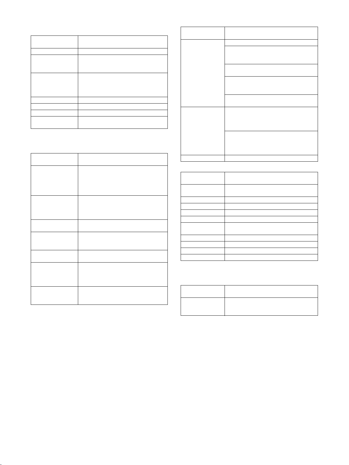
(4) Printable area
The print area of this product is shown below.
E
C
C
B
E
D
A
Paper size
Printable area
If a printer driver for Windows or Macintosh is used for printing, the
printable area will be smaller. The actual printable area depends
on the printer driver to be used.
(in mm)
Paper size A B C D E
A3 297 420 4 289 4
B4 257 364 4 242 4
A4 210 297 4 202 4
B5 182 257 4 168 4
A5 148 210 4 140 4
Japanese postcard 100 148 4 92 4
Ledger 279 432 4 271 4
Legal 216 356 4 208 4
Foolscap 216 330 4 208 4
Letter 216 279 4 208 4
Executive 184 267 4 183 4
Invoice 140 2162 4 132 4
Com-10 (envelope) 105 241 4 97 4
C5 (envelope) 162 229 4 154 4
Monarch (envelope) 98 191 4 90 4
DL (envelope) 110 220 4 102 4
ISO B5 (envelope) 176 250 4 168 4
3. Printer function memory limitation matrix
Standard
memory
Standard 128MB – 128MB 20MB 87 10MB 56
Expansion-1 128MB 128MB 256MB 84MB 367 42MB 236
Expansion-2 128MB 256MB 352MB (*1) 132MB 577 66MB 371
*1: Expansion of 256MB is limited to 224MB by the hardware restriction (Max. 352MB).
*2: When the standard chart of the printer is used.
Option
memory
capacity
AR-P20/P21, AR-NC7/NC8 SPECIFICATIONS 2 - 4
Total memory
capacity
Hold job disable
ERDH
capacity
Number of
pages (*2)
Hold job enable
Hold Job
Area capacity
Number of
pages (*2)
Page 7
[3] INSTALLATION
1. AR-P20 installation
<Before installation>
• To enable the printer expansion function, the product key must
be acquired. (For the method of acquiring the product key, contact the dealer.)
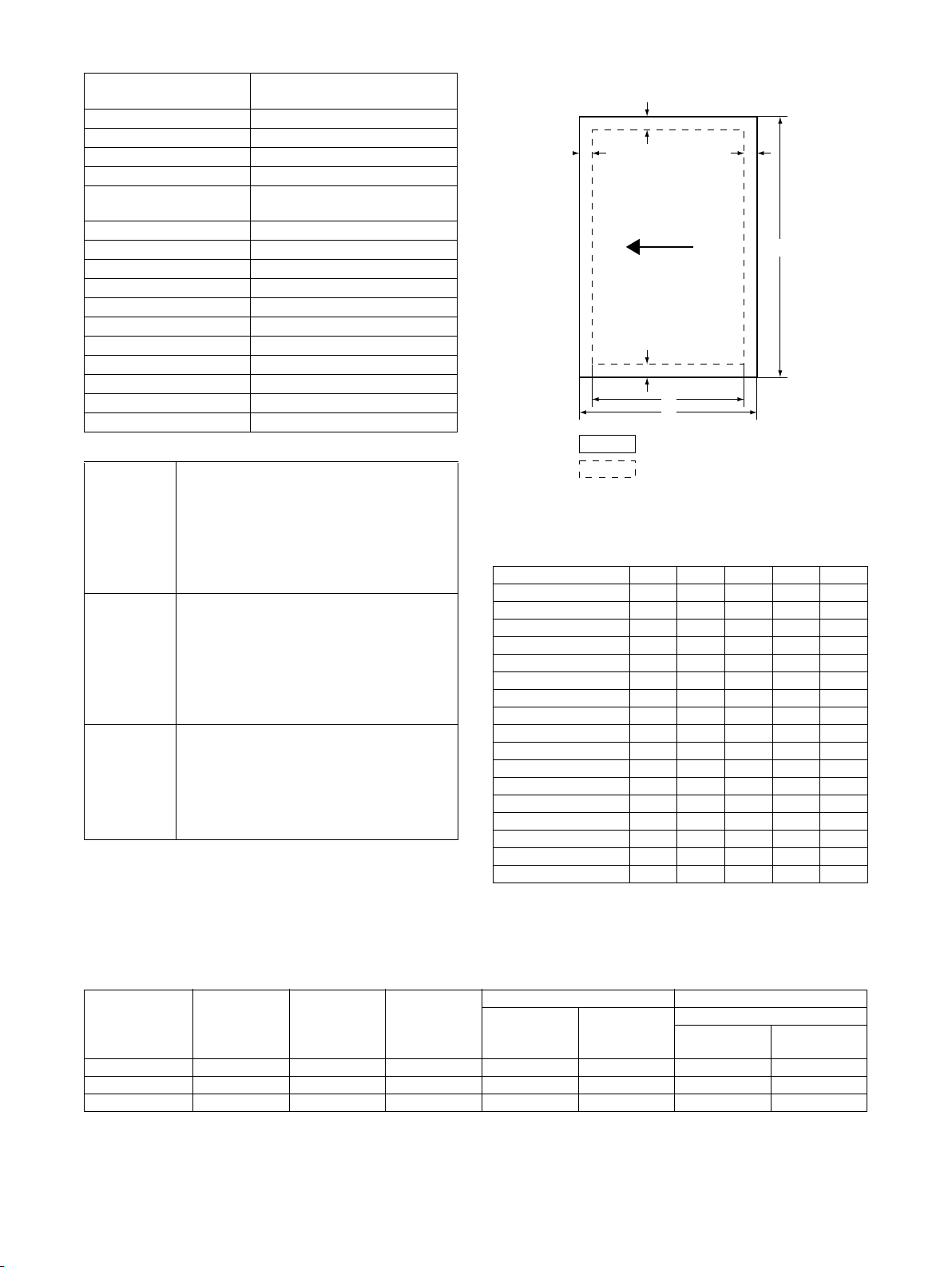
Parts included
(1) Turn off the switch of the main unit.
1) Turn the power switch of the main unit to the “OFF” position.
2) For a model with the fax function, turn off also the fax power
switch.
3) Remove the power plug of the main unit from the outlet.
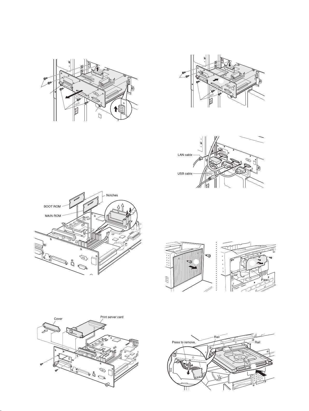
(3) Mount the printer expansion ROMs and a print
server card to the control PWB unit.
1) Remove the ROMs (MAIN and BOOT ROMs) from the control
PWB unit and replace them with the two ROMs (MAIN and
BOOT ROMs) of the printer expansion kit.
The MAIN and BOOT ROMs are indicated with “MAIN” and
“BOOT” on the labels on the ROMs respectively.
When mounting the printer expansion kit ROMs, insert them to
the same positions in the same orientations as those before
replacement until they click and ensure that the inserted
ROMs are locked with the sockets.
(2) Remove the control PWB unit.
1) If cables are connected to the control PWB, remove all cables.
2) Remove the five screws that secure the control PWB unit to
the main unit.
3) While holding the two handles, pull the control PWB unit out
until the stopper is engaged.
4) Remove the flat cable connector.
5) While using your finger to unlock the stopper, pull the control
PWB unit out of the main unit.
2) Remove the screws that secure the cover and remove the
cover.
Then, insert the connector of the print server card to the connector of the control PWB unit.
3) Secure the print server card using the screws that have been
removed from the cover.
(4) Reattach the control PWB unit.
1) Reattach the control PWB unit to the main unit.
2) Reconnect the flat cable connector that has been removed in
step (2)-4).
3) Push the unit into the main unit and secure it with the five
screws.
2)
4)
2)
3)
5)
5)
2)
3)
AR-P20/P21, AR-NC7/NC8 INSTALLATION 3 - 1
3)
3)
1)
Page 8
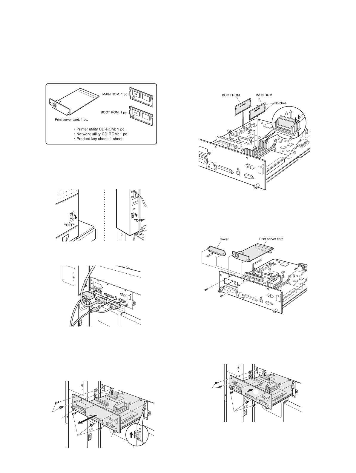
4) Reconnect the cables that have been removed in step (2)-1) to
the original positions of the control PWB unit.
Then, connect the LAN cable to the connector of the print
server card.
If another peripheral device must be installed, carry out the
following steps at the end of the installation work.
(5) Turn on the main switch of the main unit.
1) Insert the power plug of the main unit to the outlet.
2) Turn the main switch of the main unit to the “ON” position.
3) For a model with the fax function, turn on also the fax power
switch.
(7) Check the operation of the printer expansion
function.
When installation of the printer driver is complete, carry out test
page printing to check to see if printing and output can be performed normally.
(When test printing is complete, use the list print of a key operator
program to print the network settings for this machine and keep
the print carefully.)
Caution:
For acquisition of the product key, the application number
written on the separate product key sheet is needed. Keep
this sheet taking care not to lose it.
2. AR-P21 installation
<Before installation>
• To enable the printer expansion function, the product key must
be acquired. (For the method of acquiring the product key, contact the dealer.)
Parts included
(6) Enable the printer expansion function.
1) To enable the printer expansion function, use the keys on the
operation panel to enter the product key.
For entry of the product key, see the section of key operator
programs of the operation manual for the main unit.
After completing product key entry, turn off the power switch of
the main unit.
For a model with the fax function, turn off also the fax power
switch.
Turn on the power switch of the main unit again and, for a
model with the fax function, turn on also the fax power switch.
2) Carry out the network setting for the print server card.
Use a key operator program to carry out the network setting
for this machine.
For this network setting, the customer’s network environment
must be checked. Consult the network administrator to carry
out the setting.
3) According to the customer’s network environment, install the
printer driver software using the supplied CD-ROM.
For installation of the driver software to the computer and
server and its setting, follow the installation guide.
Installation of the driver software to the computer and server and
its setting must be performed by the customer or based on discussion with the customer.
(1) Turn off the switch of the main unit.
1) Turn the power switch of the main unit to the “OFF” position.
2) For a model with the fax function, turn off also the fax power
switch.
3) Remove the power plug of the main unit from the outlet.
(2) Remove the control PWB unit.
1) If cables are connected to the control PWB, remove all cables.
1)
AR-P20/P21, AR-NC7/NC8 INSTALLATION 3 - 2
Page 9
2) Remove the five screws that secure the control PWB unit to
the main unit.
3) While holding the two handles, pull the control PWB unit out
until the stopper is engaged.
4) Remove the flat cable connector.
5) While using your finger to unlock the stopper, pull the control
PWB unit out of the main unit.
(4) Reattach the control PWB unit.
1) Reattach the control PWB unit to the main unit.
2) Reconnect the flat cable connector that has been removed in
step (2)-4).
3) Push the unit into the main unit and secure it with the five
screws.
4)
2)
3)
5)
5)
2)
3)
(3) Mount the printer expansion ROMs and a print
server card to the control PWB unit.
1) Remove the ROMs (MAIN and BOOT ROMs) from the control
PWB unit and replace them with the two ROMs (MAIN and
BOOT ROMs) of the printer expansion kit.
The MAIN and BOOT ROMs are indicated with “MAIN” and
“BOOT” on the labels on the ROMs respectively.
When mounting the printer expansion kit ROMs, insert them to
the same positions in the same orientations as those before
replacement until they click and ensure that the inserted
ROMs are locked with the sockets.
2)
3)
3)
4) Reconnect the cables that have been removed in step (2)-1) to
the original positions of the control PWB unit.
Then, connect the LAN cable to the connector of the print
server card.
1)
(5) Remove the right cabinet of the main unit and the
HDD cover.
• If the saddle finisher or the like is installed at the right side of the
main unit, remove it in advance.
1) Remove the two screws that secure the right cabinet of the
main unit and then remove the right cabinet.
2) Remove the two screws that secure the HDD cover and then
remove the HDD cover.
2) Remove the screws that secure the cover and remove the
cover.
Then, insert the connector of the print server card to the connector of the control PWB unit.
3) Secure the print server card using the screws that have been
removed from the cover.
AR-P20/P21, AR-NC7/NC8 INSTALLATION 3 - 3
1)
2)
(6) Mount the HDD expansion PWB to the main unit.
1) Remove the reuse band that secures the connector from the
frame of the main unit.
2) Taking care not to catch the two connectors of the main unit,
orient the HDD expansion PWB as shown in the illustration
and gently insert it all the way into the main unit along the rails.
2)
1)
Page 10
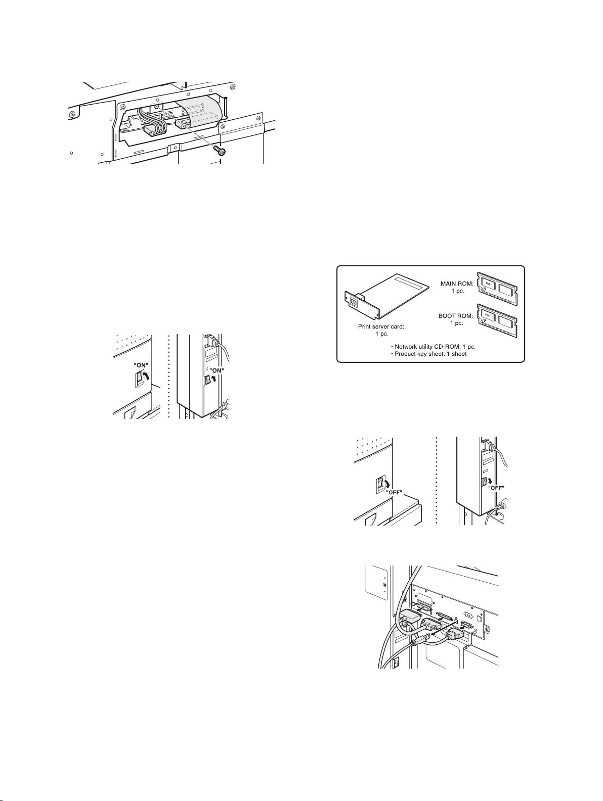
3) Use the supplied screw to secure the HDD expansion PWB to
the main unit.
4) Connect the two connectors of the main unit to the HDD
expansion PWB.
4)
4)
3)
(7) Reattach the HDD cover and the right cabinet of
the main unit.
1) Reattach the HDD cover that has been removed in step (5) to
its original position and secure it using the two screws.
2) Reattach the right cabinet of the main unit to its original position and secure it using the two screws.
If another peripheral device must be installed, carry out the
following steps at the end of the installation work.
(8) Turn on the main switch of the main unit.
1) Insert the power plug of the main unit to the outlet.
2) Turn the main switch of the main unit to the “ON” position.
3) For a model with the fax function, turn on also the fax power
switch.
(10) Check the operation.
When installation of the printer driver is complete, carry out test
page printing to check to see if printing and output can be performed normally.
(When test printing is complete, use the list print of a key operator
program to print the network settings for this machine and keep
the print carefully.)
Check to see if the HDD expansion PWB is properly mounted and
if the document filing function is enabled.
Caution:
For acquisition of the product key, the application number
written on the separate product key sheet is needed. Keep
this sheet taking care not to lose it.
3. AR-NC7 installation
<Before installation>
• To enable the network function, the product key must be
acquired. (For the method of acquiring the product key, contact
the dealer.)
Parts included
(9) Enable the printer expansion function.
1) To enable the printer expansion function, use the keys on the
operation panel to enter the product key.
For entry of the product key, see the section of key operator
programs of the operation manual for the main unit.
After completing product key entry, turn off the power switch of
the main unit.
For a model with the fax function, turn off also the fax power
switch.
Turn on the power switch of the main unit again and, for a
model with the fax function, turn on also the fax power switch.
2) Carry out the network setting for the print server card.
Use a key operator program to carry out the network setting
for this machine.
For this network setting, the customer’s network environment
must be checked. Consult the network administrator to carry
out the setting.
3) According to the customer’s network environment, install the
printer driver software using the supplied CD-ROM.
For installation of the driver software to the computer and
server and its setting, follow the installation guide.
Installation of the driver software to the computer and server and
its setting must be performed by the customer or based on discussion with the customer.
(1) Turn off the switch of the main unit.
1) Turn the power switch of the main unit to the “OFF” position.
2) For a model with the fax function, turn off also the fax power
switch.
3) Remove the power plug of the main unit from the outlet.
(2) Remove the control PWB unit.
1) If cables are connected to the control PWB, remove all cables.
AR-P20/P21, AR-NC7/NC8 INSTALLATION 3 - 4
Page 11

2) Remove the five screws that secure the control PWB unit to
the main unit.
3) While holding the two handles, pull the control PWB unit out
until the stopper is engaged.
4) Remove the flat cable connector.
5) While using your finger to unlock the stopper, pull the control
PWB unit out of the main unit.
4)
(4) Reattach the control PWB unit.
1) Reattach the control PWB unit to the main unit.
2) Reconnect the flat cable connector that has been removed in
step (2)-4).
3) Push the unit into the main unit and secure it with the five
screws.
2)
2)
3)
5)
5)
2)
3)
(3) Mount the network function ROMs and a print
server card to the control PWB unit.
1) Remove the ROMs (MAIN and BOOT ROMs) from the control
PWB unit and replace them with the network function ROMs
(MAIN and BOOT ROMs).
The MAIN and BOOT ROMs are indicated with “MAIN” and
“BOOT” on the labels on the ROMs respectively.
When mounting the network function ROMs, insert them to the
same positions in the same orientations as those before
replacement until they click and ensure that the inserted
ROMs are locked with the sockets.
3)
3)
4) Reconnect the cables that have been removed in step (2)-1) to
the original positions of the control PWB unit.
Then, connect the LAN cable to the connector of the print
server card.
If another peripheral device must be installed, carry out the
following steps at the end of the installation work.
1)
(5) Turn on the main switch of the main unit.
1) Insert the power plug of the main unit to the outlet.
2) Turn the main switch of the main unit to the “ON” position.
3) For a model with the fax function, turn on also the fax power
switch.
2) Remove the screws that secure the cover and remove the
cover.
Then, insert the connector of the print server card to the connector of the control PWB unit.
3) Secure the print server card using the screws that have been
removed from the cover.
AR-P20/P21, AR-NC7/NC8 INSTALLATION 3 - 5
(6) Enable the network function.
1) To enable the network function, use the keys on the operation
panel to enter the product key.
For entry of the product key, see the section of key operator
programs of the operation manual for the main unit.
After completing product key entry, turn off the power switch of
the main unit.
For a model with the fax function, turn off also the fax power
switch.
Turn on the power switch of the main unit again and, for a
model with the fax function, turn on also the fax power switch.
2) Carry out the network setting for the print server card.
Use a key operator program to carry out the network setting
for this machine.
For this network setting, the customer’s network environment
must be checked. Consult the network administrator to carry
out the setting.
Page 12

3) According to the customer’s network environment, install the
printer driver software using the supplied CD-ROM.
For installation of the driver software to the computer and
server and its setting, follow the installation guide.
Installation of the driver software to the computer and server and
its setting must be performed by the customer or based on discussion with the customer.
(7) Check the operation of the network function.
When installation of the printer driver is complete, carry out test
page printing to check to see if printing and output can be performed normally.
(When test printing is complete, use the list print of a key operator
program to print the network settings for this machine and keep
the print carefully.)
Caution:
For acquisition of the product key, the application number
written on the separate product key sheet is needed. Keep
this sheet taking care not to lose it.
4. AR-NC8 installation
<Before installation>
• To enable the network function, the product key must be
acquired. (For the method of acquiring the product key, contact
the dealer.)
Parts included
(2) Remove the control PWB unit.
1) If cables are connected to the control PWB, remove all cables.
1)
2) Remove the five screws that secure the control PWB unit to
the main unit.
3) While holding the two handles, pull the control PWB unit out
until the stopper is engaged.
4) Remove the flat cable connector.
5) While using your finger to unlock the stopper, pull the control
PWB unit out of the main unit.
4)
2)
3)
5)
5)
(1) Turn off the switch of the main unit.
1) Turn the power switch of the main unit to the “OFF” position.
2) For a model with the fax function, turn off also the fax power
switch.
3) Remove the power plug of the main unit from the outlet.
2)
3)
(3) Mount the network function ROMs and a print
server card to the control PWB unit.
1) Remove the ROMs (MAIN and BOOT ROMs) from the control
PWB unit and replace them with the network function ROMs
(MAIN and BOOT ROMs).
The MAIN and BOOT ROMs are indicated with “MAIN” and
“BOOT” on the labels on the ROMs respectively.
When mounting the network function ROMs, insert them to the
same positions in the same orientations as those before
replacement until they click and ensure that the inserted
ROMs are locked with the sockets.
AR-P20/P21, AR-NC7/NC8 INSTALLATION 3 - 6
Page 13

2) Remove the screws that secure the cover and remove the
cover.
Then, insert the connector of the print server card to the connector of the control PWB unit.
3) Secure the print server card using the screws that have been
removed from the cover.
(5) Remove the right cabinet of the main unit and the
HDD cover.
• If the saddle finisher or the like is installed at the right side of the
main unit, remove it in advance.
1) Remove the two screws that secure the right cabinet of the
main unit and then remove the right cabinet.
2) Remove the two screws that secure the HDD cover and then
remove the HDD cover.
(4) Reattach the control PWB unit.
1) Reattach the control PWB unit to the main unit.
2) Reconnect the flat cable connector that has been removed in
step (2)-4).
3) Push the unit into the main unit and secure it with the five
screws.
2)
3)
3)
4) Reconnect the cables that have been removed in step (2)-1) to
the original positions of the control PWB unit.
Then, connect the LAN cable to the connector of the print
server card.
1)
1)
2)
(6) Mount the HDD expansion PWB to the main unit.
1) Remove the reuse band that secures the connector from the
frame of the main unit.
2) Taking care not to catch the two connectors of the main unit,
orient the HDD expansion PWB as shown in the illustration
and gently insert it all the way into the main unit along the rails.
2)
1)
3) Use the supplied screw to secure the HDD expansion PWB to
the main unit.
4) Connect the two connectors of the main unit to the HDD
expansion PWB.
(7) Reattach the HDD cover and the right cabinet of
the main unit.
1) Reattach the HDD cover that has been removed in step (5) to
its original position and secure it using the two screws.
2) Reattach the right cabinet of the main unit to its original position and secure it using the two screws.
If another peripheral device must be installed, carry out the
following steps at the end of the installation work.
AR-P20/P21, AR-NC7/NC8 INSTALLATION 3 - 7
4)
4)
3)
Page 14

(8) Turn on the main switch of the main unit.
1) Insert the power plug of the main unit to the outlet.
2) Turn the main switch of the main unit to the “ON” position.
3) For a model with the fax function, turn on also the fax power
switch.
(9) Enable the network function.
1) To enable the network function, use the keys on the operation
panel to enter the product key.
For entry of the product key, see the section of key operator
programs of the operation manual for the main unit.
After completing product key entry, turn off the power switch of
the main unit.
For a model with the fax function, turn off also the fax power
switch.
Turn on the power switch of the main unit again and, for a
model with the fax function, turn on also the fax power switch.
2) Carry out the network setting for the print server card.
Use a key operator program to carry out the network setting
for this machine.
For this network setting, the customer’s network environment
must be checked. Consult the network administrator to carry
out the setting.
3) According to the customer’s network environment, install the
printer driver software using the supplied CD-ROM.
For installation of the driver software to the computer and
server and its setting, follow the installation guide.
Installation of the driver software to the computer and server and
its setting must be performed by the customer or based on discussion with the customer.
(10) Check the operation.
When installation of the printer driver is complete, carry out test
page printing to check to see if printing and output can be performed normally.
(When test printing is complete, use the list print of a key operator
program to print the network settings for this machine and keep
the print carefully.)
Check to see if the HDD expansion PWB is properly mounted and
if the document filing function is enabled.
Caution:
For acquisition of the product key, the application number
written on the separate product key sheet is needed. Keep
this sheet taking care not to lose it.
5. AR-PK6 installation
<Before installation>
• To enable the PS expansion function, the product key must be
acquired. (For the method of acquiring the product key, contact
the dealer.)
• For models on which the printer and network functions cannot
be used, a printer expansion ROM and a Print Server Card must
be installed in advance.
Parts included
• CD-ROM: 1pc.
• Product key sheet: 1 sheet
(1) Enable the PS expansion function.
To enable the PS expansion function, use the keys on the operation panel to enter the product key.
For entry of the product key, see the online manual included in the
supplied CD-ROM or the section of key operator programs of the
operation manual for the main unit.
After completing product key entry, turn off the power switch and
the main power switch of the main unit and then turn on the power
switch and the main power switch of the main unit again.
(2) Check the operation of the PS expansion function.
1) Use the keys on the operation panel to execute test page
printing and print the PS FONT LIST as a test print.
For test printing, see the online manual included in the CD-
ROM.
2) Installation of the driver software to the computer server and
its setting must be performed by the customer or based on discussion with the customer.
For installation of the driver software, see the installation
guide.
3) Finally, execute printing from the computer server and check
that printing is performed normally.
Caution:
For acquisition of the product key, the application number
written on the separate product key sheet is needed. Keep
this sheet taking care not to lose it.
AR-P20/P21, AR-NC7/NC8 INSTALLATION 3 - 8
Page 15

[4] CONFIGURATION REPORT (TEST PAGE)
Model name
AR-P20/P21, AR-NC7/NC8 CONFIGURATION REPORT (TEST PAGE) 4 - 1
Page 16

[5] SETTING
1. Key operator program
Level 2Level 1 Level 3
DEFAULT SETTINGS
PROHIBIT NOTICE PAGE PRINTING
PRINT DENSITY LEVEL
PROHIBIT TEST PAGE PRINTING
A4/LETTER SIZE AUTO CHANGE
PRINTER SETTINGS
Enter Key Operator Code
NETWORK SETTINGS
INTERFACE SETTINGS
IP ADDRESS SETTING
ENABLE TCP/IP
ENABLE NetWare
ENABLE EtherTalk
ENABLE NetBEUI
RESET THE NIC
TANDEM SETTING
PING COMMAND
A. Printer settings
(1) Default settings
These programs are used to adjust the settings of various printer
functions.
Prohibit notice page printing
This program is used to disable notice page printing.
Normally this program is set to not print a notice page.
Print density level
This program is used to adjust the lightness or darkness of prints.
Five levels are provided for density adjustment. These are repre-
sented by numbers displayed on the touch panel. Among the displayed numbers, a smaller value indicates lighter density and a
larger value indicates a darker density.
Prohibit test page printing
This program is used to disable test page printing.
When the program is turned on, the PRINTER TEST PAGE in the
custom settings cannot be printed.
A4/letter size auto change
If this program is set, and printing onto 8-1/2" x 11" size paper is
selected but not available, the printer will automatically substitute
A4 size paper in place of 8-1/2" x 11" paper if A4 paper is available.
∗ 8-1/2" x 11" paper cannot be automatically selected in place of
A4.
NOTE: When 8-1/2" x 11" size is specified for a document
attached to an E-mail that has been transmitted from a
foreign country and A4 size paper is not installed in the
printer, printing cannot be done without operator
intervention. If this program is set, printing will be
executed without intervention if a paper tray is loaded with
A4 paper.
HEXADECIMAL DUMP MODE
I/O TIMEOUT
ENABLE PARALLEL PORT
PARALLEL PORT EMULATION SWITCHING
ENABLE USB PORT
USB PORT EMULATION SWITCHING
ENABLE NETWORK PORT
NETWORK PORT EMULATION SWITCHING
PORT SWITCHING METHOD
PARALLEL PORT ECP SETTING
(2) Interface settings
These programs are used to control data transmitted to the parallel port, USB port or network port of this printer.
Hexadecimal dump mode
This program is used to output the print data from a computer in
the hexadecimal dump format with corresponding characters
(ASCII). This program is used to check proper transmission of
print data from the computer to the printer.
Output example of hexadecimal dump mode
I/O timeout
This program is used to set the length of time to wait for an I/O to
complete a job on the parallel port or the network port. If the data
stream to the port does not transmit data for a length of time
exceeding the timeout, the job will cancel and the next job will start
processing.
The I/O timeout setting is used to set the amount of time after
which an I/O timeout will occur when waiting for print data.
Default setting: 20 seconds
NOTE: The allowable range of the time is 1 to 999 seconds.
Enable parallel port
This program is used to enable or disable printing from the parallel
port.
Default setting: Enable
AR-P20/P21, AR-NC7/NC8 INSTALLATION 5 - 1
Page 17

Parallel port emulation switching
This program is used to specify a printer language to emulate when
the printer is connected to a computer through the parallel port.
Setting items Description
Auto The printer language will switch automatically in
accordance with the data from the computer.
PostScript PostScript emulation is used to print the data
from the computer. (An optional PS3 expansion
kit is needed.)
PCL PCL emulation is used to print the data from the
computer.
NOTE: It is recommended to set "AUTO" (default setting) unless
an error due to this setting occurs frequently.
Enable USB port
This program is used to enable or disable printing from the USB
port.
Default setting: Enable
USB port emulation switching
If the machine is connected using the USB port, select the emulated printer language.
The setting items are the same as those of "Parallel port emulation
switching".
NOTE: It is recommended to set "AUTO" (default setting) unless
an error due to this setting occurs frequently.
Enable network port
This program is used to enable or disable printing from the network port.
Default setting: Enable
Network port emulation switching
This program is used to specify a printer language to emulate
when the printer is connected to a computer through the network
port.
The setting items are the same as those of "Parallel port emulation
switching".
NOTE: It is recommended to set "AUTO" (default setting) unless
an error due to this setting occurs frequently.
Port switching method
The machine can use the three ports shown below for printing.
This program is used to select when switching between ports will
take place. "SWITCH AT END OF JOB" or "SWITCH AFTER I/O
TIMEOUT" can be selected. When "SWITCH AT END OF JOB" is
selected, the port will be automatically selected after each print job
is completed. When "SWITCH AFTER I/O TIMEOUT" is selected,
the port will be automatically selected if the time set in the I/O Timeout program elapses.
• Parallel port
• USB port
• Network port
Parallel port ECP setting
This is used to enable bi-directional communication through the Centronix interface.
Select "Parallel port ECP setting" to enable data transmission both
from the computer to the printer and from the printer to the computer.
Normally ECP mode is not selected.
B. Network settings
These programs are set when this product is used as a network
printer.
After you complete the setting for one program, you must exit the
key operator programs, turn off the main switch, wait briefly, and
then turn on the main switch again before any other programs can
be set. The program that was set will be effective after the power
is turned on.
NOTE: For setting and modification of "Network settings", be sure
to consult with the network administrator.
IP address setting
When using this product in a network that uses the TCP/IP protocol, use this program to set the IP address (IP address, IP subnet
mask, and IP gateway) of this product. The program is set to
ENABLE DHCP by factory default setting, which obtains the IP
address setting automatically. When using this product on a TCP/
IP network, be sure to turn on the "Enable TCP/IP" program
below.
If DHCP is used, the IP address assigned to the machine may
be changed automatically on occasion.
If this happens, printing will not be possible.
Enable TCP/IP
When using this product in a network that uses the TCP/IP protocol, set this program. Also set the IP address using the program
"IP address setting" above.
Default setting: Enable
Enable NetWare
When using this product in a network that uses the NetWare protocol, set this program.
Default setting: Enable
Enable EtherTalk
When using this product in a network that uses the EtherTalk protocol, set this program.
Default setting: Enable
Enable NetBEUI
When using this product in a network that uses the NetBEUI protocol, set this program.
Default setting: Enable
Reset the NIC
This program is used to reset all setting items of NIC (Network
Interface Card) of this product to the factory default settings.
NOTE: If any of the [NETWORK SETTINGS] were changed prior
to execution of this program, you must turn off the power
switch after exiting the key operator program, wait briefly,
and then turn on the power switch to make the factory
default settings take effect.
Tandem setting
This setting is used to configure the IP address and port number of
the client printer when you wish to have two machines (which are
used as TCP/IP network printers) print in tandem.
Tandem printing is not possible if the other machine is a different
model than your machine.
The factory default setting for the port number is [50001]. Unless
you experience difficulty with this setting, it does not need to be
changed.
The tandem function can also be prohibited, or the reception of
tandem data from the other machine can be prohibited. (Normally
this is not necessary.)
To prohibit the tandem function, select "DISABLING OF MASTER
MACHINE MODE".
To prohibit reception of tandem data from the other machine,
select "DISABLING OF SLAVE MACHINE MODE".
NOTE: To use the tandem function when auditing mode is
enabled, the same account number must be entered on
both machines. If the same account number is not
entered, only the server machine may print or the printed
pages may not be added to the correct account.
PING command
This program is used to check if the machine and a computer connected to the network can communicate.
Enter the IP address of the computer that you wish to check and
touch the [START] key. A message will appear indicating whether
or not there was a response from the computer.
AR-P20/P21, AR-NC7/NC8 INSTALLATION 5 - 2
Page 18

[6] SIMULATION
1. List
Code
Main Sub
67 2 Used to check the operation of the parallel I/F of
the printer. (This simulation is for production only,
and requires a special tool for execution. Not
used in the market.)
11 Used to set YES/NO of the parallel I/F select
signal of the printer.
16 Used to check the operation of the network card.
Function (Purpose)
2. Details
67
67-2
Purpose Operation test/Check
Function
(Purpose)
Section MFP controller
Item Operation Interface/Communication
Operation/Procedure
(Display message)
WAITING Waiting
READY Check start OK
OK Check end (Normal)
STAGE*NG Check end (Error in stage *. *: 1 - 11)
SIMULATION 67-2
CENTRO PORT CHECK.
CENTRO PORT: READY
SIMULATION 67-2
CENTRO PORT CHECK.
CENTRO PORT: OK (or STAGE7 NG)
Used to check the operation of the parallel I/F of
the printer. (This simulation is for production only,
and requires a special tool for execution. Not used
in the market.)
lWith READY displayed,
press [START] key.
Press [CUSTOM SETTINGS] key.
67-11
Purpose Setting
Function
(Purpose)
Used to set YES/NO of the parallel I/F select
signal of the printer.
Section MFP controller
Item Operation Interface/Communication
Operation/Procedure
1) Enter the number corresponding to the select IN signal YES/
NO setting with 10-key.
Item Default
0OFF 1
1ON
2) Press [START] key.
When the printer parallel I/F is used and a trouble is generated in
the communication between the PC and the printer, change the
setting of this simulation.
SIMULATION 67-11
CENTRO SELECT IN SIGNAL SETTING. SELECT 0-1, AND PRESS
START.
0. OFF
1. ON
67-16
Purpose Operation test/Check
Function
Used to check the operation of the network card.
(Purpose)
Section MFP controller
Item Operation Interface/Communication
Operation/Procedure
During check, "CHECKING" is displayed. When check is completed normally, "OK" is displayed. In case of an error, "NG" is displayed.
(Display message)
CHECKING Checking
OK Check end (Normal)
NG Check end (Error)
SIMULATION 67-16
NETWORK INTERFACE CARD CHECK.
NIC: CHECKING
Check end Press [CUSTOM SETTINGS] key.
SIMULATION 67-16
NETWORK INTERFACE CARD CHECK.
NIC: OK (or NG)
AR-P20/P21, AR-NC7/NC8 SIMULATION 6 - 1
Page 19

[7] ELECTRICAL SECTION
1. Block diagram
A. MFP CONTROLLER PWB
CN8
5V INPUT
3.3V INPUT
IC718
DC-DC Converter
3.3V(I/O)
2.5V
N:1.3V / U:1.5V (Core)
OSC
X700
N :74.9MHz
IC9
Clock buffer
CN10
JTAG
U :66.666MHz
TDI, TMS, TDO ,TCK, TRST*
5V
Reset IC
PST598DN
PONRST
COLDRST
CPURST
3_EXTRQST
3.3V
IC47
System
NMI, INT0*
IC753
Reset IC
PST598IN
IC700
Controller
SysAD[54:33]
SysCMD[8:0], SysAD[63:0]
Flash DIMM
LA[22:2]
Buffer
IC726,
Address
CN4,5,6
729,732
CN7
Mask DIMM
MEMD[31:0]
IC727,
LCX245
728,730,731
FAX I/F (CN16)
Buffer
IC742,
Address
INT1*,INT2*,INT3*
LCX245
743,744,745
IC32
I/O G/A
POF
MSW-MON,WAKE-UP*
IC738,739,
740,741
CPU Block
Mask
DIMM
(32MB)
Flash
DIMM
MEMD[31:0]
SysAD[31:0]
PS Kanji
(8MB)
Slot1,2,3
LA[22:2]
Address Buffer Gate
SysAD[54:34]
CPU
FAX I/F
Buffer
SDRAM
SDRAM
MAA[12:0]
IC20
N model :
RTC
DIMM
128/256MB
(128MB)
ON BOARD
MD[63:0]
RM7065
U model :
I/F
IEEE1284
LVX161284
IOA[17:0]
LDATA[15:0]
TX4955
Driver
232C
I/O G/A
(ASIC1)
SRAM
N : 2Mbit
EEPROM
Buffer
Address
RIC I/F
U : 4Mbit
(64Kbit)
TD62503F
IOD[15:0]
Gate
Data
Scanner I/F
Controller
LCD
PCI Bus
(32MB)
SDRAM
ICU ASIC
USB
Controller
Soft-NIC
IDE
Controller
Engine I/F
PM2060i
PM-22A PM-22B
USB I/F
IDE I/F
General
CPU
U model : TX4955
N model : RM7065
SysAD[63:0]
SYSTEM
Controller
SysCMD[8:0]
Dracula III
AR-P20/P21, AR-NC7/NC8 ELECTRICAL SECTION 7 - 1
Page 20

OSC
X700
N : 74.9MHz
U : 66.666MHz
Clock
buffer
IC9
DRCLK
MEMCLK0
MD[63:0]
MAA[12:0]
SDRAM Block ( Standard & Option )
SDRAM
IC4,5,6,7
SDQMA[7:0]
128MB
(ON BOARD)
MWE
MCS0
MRASA
MCASA
BSEL0A,1A
CKEA
System
Controller
MEMCLK1,2,3,4
BGA
IC700
420pin-
144pin
DIMM Slot
SO-DIMM
MWE
CN3
(128,256
MCS1A,2A
MRASA
MCASA
BSEL0A,1A
MB)
CKEA
SDA,SCL
3.3V
Q19
FET
LA[22:2]
Buffer
IC726,
Address
VCSW
729,732
SW2
DIP SW
CN4:8MB-
DIMM Slot
MEMD[31:0]
IC727,
LCX245
728,730,731
Flash
Flash
CN5:8MB-
ROMBUFOE*
Flash
CN6:8MB-
ROMBUFDIR*
CN7:32MB
FMCS8:CN4
-Mask
(PS Kanji)
FMCS10:CN5
FMCS12:CN6
CODECS0*
CODECS1*
CODECS2*
FMCS0:CN7
I/O G/A
CODECS3*
FONTCS0*
FONTCS1*
FONTCS2*
FMCS2:CN7
FMCS4:CN7
FMCS6:CN7
IC32
FONTCS3*
FONTCS4*
FONTCS5*
FONTCS6*
QFP
240pin-
FONTCS7*
ROM Block (Flash & Mask)
SysAD[54:34]
SysAD[31:0]
AR-P20/P21, AR-NC7/NC8 ELECTRICAL SECTION 7 - 2
System
Controller
IC700
420pin-
BGA
Page 21

CN1
IEEE1284 I/F
CN14
Engine I/F
RIC I/F (RS232C)
CN8
CN702
Scanner I/F
(BT1)
Battery
IC15
LVX161284
IC42
232C Driver
IC41
I/O G/A
ALE,ALE-H
System
IC700
Controller
420pin-BGA
I/O Block ( EEPROM & Misc I/O )
TD62503F
IC32
IC733,
735,737
LCX373
LDATA[15:0]
IC38
Xtal
TD62503F
32.768kHz
240pin-QFP
IOA[15,14,6:1]
IOD[7:0]
5V
IC40
NJU6356
RTC
LCX245
IC734,736
Switcher
X7
OSC
SW0,SW1
DIP-SW
14.7456MHz
IC36
64Kbit
EEPROM
IOD[7:0]
IOA[13:1]
IC53
Controller
LCD
IOA[14:1]
3.3V
IOD[15:0]
Switcher
IC55
SRAM
N:2Mbit
IOD[7:0]
IOA[18:0]
U:4Mbit
OSC X3
33.333MHz
IC29
Clock buffer
System
Controller
IC700
420pin-BGA
IC32
I/O G/A
PCIREQx
PCIGNTx
IC27
SDRAM
240pin-QFP
66MHz
OSC X1
32MB
I/F
CN702
Scanner
160pin-QFP
160pin-QFP
PM22-B IC723
PM22-A IC721
ICU ASIC
Engine
IC18
LVDS
IC725
PM2060i
IC25
304pin-QFP
I/F
CN8
IC18
Buffer
OSC
Selector
52pin-QFP
OSC
OSC
OSC
X703
X5
X2
40.57MHz
X4
31.554MHz
66.666MHz
64MHz
CN701
IDE I/F
24MHz
XTAL X701
144pin-QFP
IDE Controller IC756
USB Controller
SOFT-NIC
CN700
USB I/F
CN9
IC703 100pin-QFP
(100Base-T)
PCI-Bus
PCI Block ( ICU & Option )
AR-P20/P21, AR-NC7/NC8 ELECTRICAL SECTION 7 - 3
Page 22

2. SOFT NIC PWB
CN1
(to controller)
PCI-Bus
Ethernet
Controller
DP83816
IC1
CN3
LAN I/F
EEPROM
IC3
1Kbit
OSC
X1
25MHz
AR-P20/P21, AR-NC7/NC8 ELECTRICAL SECTION 7 - 4
Page 23

q
PARTS GUIDE
CODE :
DIGITAL MULTIFUNCTIONAL
SYSTEM OPTIONS
PRINTER EXPANSION KIT/
PRINT SERVER CARD
AR-P20/P21
MODEL
CONTENTS
1
Packing material&Accessories[AR-P20]
2
Packing material&Accessories[AR-NC7]
3
Packing material&Accessories[AR-P21/NC8]
4
Soft NIC PWB unit
■
index
AR-NC7/NC8
Parts marked with "!" are important for maintaining the safety of the set. Be sure to replace these parts with specified
ones for maintaining the safety and performance of the set.
This document has been published to be used
SHARP CORPORATION
for after sales service only.
The contents are subject to change without notice.
Page 24

DEFINITION
The definition of each Rank is as follows and also noted in the list
Rank A : Maintenance parts, and consumable parts which are not included in but closely related to maintenance parts
Rank B : Performance/function parts (sensors, clutches, and other electrical parts), consumable parts
Rank E : Unit parts including PWB
Rank D : Preparation parts (External fitting, packing, parts packed together)
Rank C : Parts other than the above (excluding sub components of PWB)
Because parts marked with "!" is indispensable for the machine safety maintenance and operation, it must be replaced with
the parts specific to the product specification.
F Other than this Parts Guide, please refer to documents Service Manual(including Circuit Diagram)of this model.
F Please use the 13 digit code described in the right hand corner of front cover of the document, when you place an order.
F For U.S. only-Use order codes provided in advertising literature. Do not order from parts department.
Packing material&Accessories[AR-P20]
1
PRICE
NEW
NO. PARTS CODE
CDSKA0029FC31 BH D Driver CD EXA
1
CDSKA0032FC31 BH D NIC CD EX
3 SPAKP1031DCZZ AA D Vinyl bag
4 SPAK-546ECCZZ AB D Vinyl bag(125×230)
5 SPAKA6485FCZZ AP D Spacer
6 DUNT-7314FC12 BK N E Soft NIC PWB unit
TINSE2840FCZZ AN N D Ope.manual(PCL-INS-U) [English]
TINSF2842FCZZ BB N D Ope.manual(PCL-INS-F) [French]
TINSS2843FCZZ BB N D Ope.manual(PCL-INS-S) [Spanish]
8
TINSE2858FCZZ AK N D Ope.manual(PC-INS-U) [English]
TINSF2860FCZZ BA N D Ope.manual(PC-INS-F) [French]
TINSS2861FCZZ BA N D Ope.manual(PC-INS-S) [Spanish]
9 TCADZ1708FCZZ AF N D Product key sheet E
10 TCADZ1699FCZZ AL N D Inst.card EX4
RANK
MARK
PART
RANK
DESCRIPTION
Packing material&Accessories[AR-P20]
1
9,10
1
8
3
4
5
1
6
– 1 –
FCP08590
Page 25

Packing material&Accessories[AR-NC7]
2
PRICE
NEW
NO. PARTS CODE
1 CDSKA0032FC31 BH D NIC CD EX
2 SPAKA6707FCZZ AF N D Spacer A
3 DUNT-7314FC12 BK N E Soft NIC PWB unit
4 SPAK-546ECCZZ AB D Vinyl bag(125×230)
6 SPAKP1031DCZZ AA D Vinyl bag
8 SPAKA6708FCZZ AH N D Spacer B
9 TCADZ1710FCZZ AF N D Product key sheet E
10 TCADZ1701FCZZ AL N D Inst.card EX4
Packing material&Accessories[AR-NC7]
2
RANK
MARK
PART
RANK
9
10
DESCRIPTION
8
1
3
4
6
2
FCP08591
– 2 –
Page 26

Packing material&Accessories[AR-P21/NC8]
3
PRICE
NEW
NO. PARTS CODE
CDSKA0029FC33 BH D Driver CD
1
CDSKA0032FC31 BH D NIC CD EX
2 DUNT-7314FC12 BK N E Soft NIC PWB unit
4 SPAK-546ECCZZ AB D Vinyl bag(125×230)
5 SPAKA6751FCZZ AG N D Spacer A
6 SPAKA6752FCZZ AG N D Spacer A
7 SPAKA6753FCZZ AN N D HDD add
9 SPAKP1031DCZZ AA D Vinyl bag
10 SPAKP2374ACZZ AD D Vinyl bag
11 SSAKA0006UCZZ AA D Vinyl bag(50X60)
TCADZ6033FCZZ AF N D Inst.card [AR-P21]
12
TCADZ6034FCZZ AP N D Inst.card [AR-NC8]
TCADZ6035FCZZ AF N D Product key sheet E [AR-P21]
13
TCADZ6036FCZZ AF N D Product key sheet E [AR-NC8]
TINSE2840FCZZ AN N D Ope.manual(PCL-INS) [English][AR-P21]
TINSE2858FCZZ AK N D Ope.manual(PC-INS) [English][AR-P21]
TINSF2842FCZZ BB N D Ope.manual(PCL-INS) [French][AR-P21]
14
TINSF2860FCZZ BA N D Ope.manual(PC-INS) [French][AR-P21]
TINSS2843FCZZ BB N D Ope.manual(PCL-INS) [Spanish][AR-P21]
TINSS2861FCZZ BA N D Ope.manual(PC-INS) [Spanish][AR-P21]
15 XBBS740P08000 AA C Screw(4×8)
16 CCOVP1815FC01 AP C HDD cover
17 DUNT-7368FCZZ CD E HDD UNIT(40G)
18 JHNDM0177FCZZ AD C HDD handle
19 LPLTM6258FCZ2 AE C HDD fixing plate
20 LX-BZ0975FCZZ AC C Screw
21 LX-BZ1022LCZZ AB C Screw
22 PCUSG0378FCZZ AF C Cushion
RANK
MARK
PART
RANK
DESCRIPTION
Soft NIC PWB unit
4
PRICE
NEW
NO. PARTS CODE
1 QCNCW1153FCZZ AM C Connctor(TX24-100R12) [CN1]
2 QSOCN0010QSZZ AV C Connctor(J0026D21G) [CN3]
3 RCRUA0019QSZZ AR B Crystal(25MHz OSC) [X1]
4 RFILN0010QSZZ AB C Coil(BLM18BB121SN1D) [L1,L2,L3,L4,L8]
5 RFILZ6003RC01 AB C Filter(EMIFIL103) [L7]
6 VCCCCZ1HH100D AA C Capacitor(50WV 10pF) [C4]
7 VCCCCZ1HH101J AA C Capacitor(50WV 100pF) [C36]
8 VCCUCY1AJ105Z AC C Capacitor(10WV 1.0µF) [C34]
9 VCEASX1CN106M AC C Capacitor(16WV 10µF) [C25]
10 VCEASX1CN107M AF C Capacitor(16WV 100µF) [C2,C35]
11 VCEASX1CN226M AC C Capacitor(16WV 22µF) [C26]
VCKYCZ1CB103K AA C Capacitor(16WV 0.01µF) [C9,C10,C11,C12,C13]
12
VCKYCZ1CB103K AA C Capacitor(16WV 0.01µF) [C14,C15,C16,C18,C20]
VCKYCZ1CB103K AA C Capacitor(16WV 0.01µF) [C22,C24,C30,C32]
VCKYCZ1CF104Z AB C Capacitor(16WV 0.1µF) [C3,C5,C6,C7,C8,C27,C28]
13
VCKYCZ1CF104Z AB C Capacitor(16WV 0.1µF) [C29,C31,C33]
14 VCKYCZ1HB102K AA C Capacitor(50WV 1000pF) [C17,C19,C21,C23,C37,C39]
15 VHIDP83816N-1 AY B IC(DP83816AVNG) [IC1]
16 VHI93C46VI+-1 AE B IC(CAT93C46VI) [IC3]
VRS-CZ1JD000J AA C Resistor(1/16W 0Ω ±5%) [R3,R11,R15,R23]
17
VRS-CZ1JD000J AA C Resistor(1/16W 0Ω ±5%) [R26,R27,R35]
18 VRS-CZ1JD100J AA C Resistor(1/16W 10Ω ±5%) [R1,R19,R29]
19 VRS-CZ1JD103J AA C Resistor(1/16W 10KΩ ±5%) [R18,R20,R24,R36]
20 VRS-CZ1JD330J AA C Resistor(1/16W 33Ω ±5%) [R34]
21 VRS-CZ1JD471J AA C Resistor(1/16W 470Ω ±5%) [R12,R2]
22 VRSCY1JR49R9F AA C Resistor(1/16W 49.9Ω ±1%) [R4,R13]
23 VRSCY1JR54R9F AA C Resistor(1/16W 54.9Ω ±1%) [R7,R16]
24 LSTYM0333FCZZ AF C NIC stay
25 XBPS730P06K00 AA N C Screw(3×6K)
(Unit)
901 DUNT-7314FC12 BK N E Soft NIC PWB unit
RANK
MARK
PART
RANK
DESCRIPTION
– 3 –
Page 27

3
Packing material&Accessories[AR-P21/NC8]
15
11
10
7
21
6
22
20
7
2
4
1
17
22
21
20
19
16
22
20
18
21
22
20
21
13
12,
14
9
9
5
FCP08592
– 4 –
Page 28

■
Index
PARTS CODE NO.
[C]
CCOVP1815FC01
CDSKA0029FC31
CDSKA0029FC33
CDSKA0032FC31
DUNT-7314FC12
DUNT-7368FCZZ
JHNDM0177FCZZ
LPLTM6258FCZ2
LSTYM0333FCZZ
LX-BZ0975FCZZ
LX-BZ1022LCZZ
PCUSG0378FCZZ
QCNCW1153FCZZ
QSOCN0010QSZZ
RCRUA0019QSZZ
RFILN0010QSZZ
RFILZ6003RC01
SPAK-546ECCZZ
SPAKA6485FCZZ
SPAKA6707FCZZ
SPAKA6708FCZZ
SPAKA6751FCZZ
SPAKA6752FCZZ
SPAKA6753FCZZ
SPAKP1031DCZZ
SPAKP2374ACZZ
SSAKA0006UCZZ
TCADZ1699FCZZ
TCADZ1701FCZZ
TCADZ1708FCZZ
TCADZ1710FCZZ
TCADZ6033FCZZ
TCADZ6034FCZZ
TCADZ6035FCZZ
TCADZ6036FCZZ
TINSE2840FCZZ
TINSE2858FCZZ
TINSF2842FCZZ
TINSF2860FCZZ
TINSS2843FCZZ
TINSS2861FCZZ
VCCCCZ1HH100D
VCCCCZ1HH101J
VCCUCY1AJ105Z
VCEASX1CN106M
VCEASX1CN107M
VCEASX1CN226M
VCKYCZ1CB103K
VCKYCZ1CF104Z
VCKYCZ1HB102K
VHI93C46VI+-1
VHIDP83816N-1
VRSCY1JR49R9F
VRSCY1JR54R9F
"
"
[D]
"
"
"
[J]
[L]
[P]
[Q]
[R]
[S]
"
"
"
"
[T]
"
"
"
"
"
"
[V]
PRICE
NEW
MARK
PART
RANK
RANK
3- 16 AP C
1- 1 BH D
3- 1 BH D
1- 1 BH D
2- 1 BH D
3- 1 BH D
1- 6 BK N E
2- 3 BK N E
3- 2 BK N E
4- 901 BK N E
3- 17 CD E
3- 18 AD C
3- 19 AE C
4- 24 AF C
3- 20 AC C
3- 21 AB C
3- 22 AF C
4- 1 AM C
4- 2 AV C
4- 3 AR B
4- 4 AB C
4- 5 AB C
1- 4 AB D
2- 4 AB D
3- 4 AB D
1- 5 AP D
2- 2 AF N D
2- 8 AH N D
3- 5 AG N D
3- 6 AG N D
3- 7 AN N D
1- 3 AA D
2- 6 AA D
3- 9 AA D
3- 10 AD D
3- 11 AA D
1- 10 AL N D
2- 10 AL N D
1- 9 AF N D
2- 9 AF N D
3- 12 AF N D
3- 12 AP N D
3- 13 AF N D
3- 13 AF N D
1- 8 AN N D
3- 14 AN N D
1- 8 AK N D
3- 14 AK N D
1- 8 BB N D
3- 14 BB N D
1- 8 BA N D
3- 14 BA N D
1- 8 BB N D
3- 14 BB N D
1- 8 BA N D
3- 14 BA N D
4- 6 AA C
4- 7 AA C
4- 8 AC C
4- 9 AC C
4- 10 AF C
4- 11 AC C
4- 12 AA C
4- 13 AB C
4- 14 AA C
4- 16 AE B
4- 15 AY B
4- 22 AA C
4- 23 AA C
PARTS CODE NO.
VRS-CZ1JD000J
VRS-CZ1JD100J
VRS-CZ1JD103J
VRS-CZ1JD330J
VRS-CZ1JD471J
[X]
XBBS740P08000
XBPS730P06K00
PRICE
NEW
MARK
PART
RANK
RANK
4- 17 AA C
4- 18 AA C
4- 19 AA C
4- 20 AA C
4- 21 AA C
3- 15 AA C
4- 25 AA N C
– 5 –
Page 29

Memo
Page 30

LEAD-FREE SOLDER
The PWB’s of this model employs lead-free solder. The “LF” marks indicated on the PWB’s and the Service Manual mean “Lead-Free” solder.
The alphabet following the LF mark shows the kind of lead-free solder.
Example:
<Solder composition code of lead-free solder>
Solder composition
Sn-Ag-Cu
Sn-Ag-Bi
Sn-Ag-Bi-Cu
Sn-Zn-Bi
Sn-In-Ag-Bi
Sn-Cu-Ni
Sn-Ag-Sb
Bi-Sn-Ag-P
Bi-Sn-Ag
5mm
Lead-Free
Solder composition
code (Refer to the
table at the right.)
a
(1) NOTE FOR THE USE OF LEAD-FREE SOLDER THREAD
When repairing a lead-free solder PWB, use lead-free solder thread.
Never use conventional lead solder thread, which may cause a breakdown or an accident.
Since the melting point of lead-free solder thread is about 40°C higher than that of conventional lead solder thread, the use of the exclusive-use
soldering iron is recommendable.
Solder composition code
a
b
z
i
n
s
p
(2) NOTE FOR SOLDERING WORK
Since the melting point of lead-free solder is about 220°C, which is about 40°C higher than that of conventional lead solder, and its soldering capacity is
inferior to conventional one, it is apt to keep the soldering iron in contact with the PWB for longer time. This may cause land separation or may exceed
the heat-resistive temperature of components. Use enough care to separate the soldering iron from the PWB when completion of soldering is
confirmed.
Since lead-free solder includes a greater quantity of tin, the iron tip may corrode easily. Turn ON/OFF the soldering iron power frequently.
If different-kind solder remains on the soldering iron tip, it is melted together with lead-free solder. To avoid this, clean the soldering iron tip after
completion of soldering work.
If the soldering iron tip is discolored black during soldering work, clean and file the tip with steel wool or a fine filer.
Page 31

CAUTION FOR BATTERY REPLACEMENT
(Danish) ADVARSEL !
Lithiumbatteri – Eksplosionsfare ved fejlagtig håndtering.
(English) Caution !
Danger of explosion if battery is incorrectly replaced.
Dispose of used batteries according to manufacturer’s instructions.
(Finnish) VAROITUS
Paristo voi räjähtää, jos se on virheellisesti asennettu.
Vaihda paristo ainoastaan laitevalmistajan suosittelemaan
tyyppiin. Hävitä käytetty paristo valmistajan ohjeiden
(French) ATTENTION
Il y a danger d’explosion s’ il y a remplacement incorrect
de la batterie. Remplacer uniquement avec une batterie du
même type ou d’un type équivalent recommandé par
Mettre au rebut les batteries usagées conformément aux
(Swedish) VARNING
(German) Achtung
Explosionsgefahr bei Verwendung inkorrekter Batterien.
Als Ersatzbatterien dürfen nur Batterien vom gleichen Typ oder
vom Hersteller empfohlene Batterien verwendet werden.
Entsorgung der gebrauchten Batterien nur nach den vom
Udskiftning må kun ske med batteri
af samme fabrikat og type.
Levér det brugte batteri tilbage til leverandoren.
Replace only with the same or equivalent type
recommended by the manufacturer.
mukaisesti.
le constructeur.
instructions du fabricant.
Explosionsfara vid felaktigt batteribyte.
Använd samma batterityp eller en ekvivalent
typ som rekommenderas av apparattillverkaren.
Kassera använt batteri enligt fabrikantens
instruktion.
Hersteller angegebenen Anweisungen.
CAUTION FOR BATTERY DISPOSAL
(For USA, CANADA)
THIS PRODUCT CONTAINS A LITHIUM PRIMARY
(MANGANESS DIOXIDE) MEMORY BACK-UP BATTERY
THAT MUST BE DISPOSED OF PROPERLY. REMOVE THE
BATTERY FROM THE PRODUCT AND CONTACT YOUR
LOCAL ENVIRONMENTAL AGENCIES FOR INFORMATION
ON RECYCLING AND DISPOSAL OPTIONS.
CE PRODUIT CONTIENT UNE PILE DE SAUVEGARDE DE
MÉMOIRE LITHIUM PRIMAIRE (DIOXYDE DE MANGANÈSE)
QUI DOIT ÊTRE TRAITÉE CORRECTEMENT. ENLEVEZ LA
PILE DU PRODUIT ET PRENEZ CONTACT AVEC VOTRE
AGENCE ENVIRONNEMENTALE LOCALE POUR DES
INFORMATIONS SUR LES MÉTHODES DE RECYCLAGE ET
"BATTERY DISPOSAL"
"TRAITEMENT DES PILES USAGÉES"
DE TRAITEMENT.
Page 32

COPYRIGHT © 2005 BY SHARP CORPORATION
All rights reserved.
Printed in Japan.
No part of this publication may be reproduced,
stored in a retrieval system, or transmitted,
in any form or by any means,
electronic; mechanical; photocopying; recording or otherwise
without prior written permission of the publisher.
Trademark acknowledgements
• Microsoft® Windows® operating system is a trademark or copyright of Microsoft
Corporation in the U.S.A. and other countries.
®
• Windows
and Windows
U.S.A. and other countries.
• IBM and PC/AT are trademarks of International Business Machines Corporation.
• Acrobat
reserved. Adobe, the Adobe logo, Acrobat, and the Acrobat logo are trademarks of
Adobe Systems Incorporated.
• All other trademarks and copyrights are the property of their respective owners.
95, Windows® 98, Windows® Me, Windows NT® 4.0, Windows® 2000,
®
XP are trademarks or copyrights of Microsoft Corporation in the
®
Reader Copyright® 1987- 2002 Adobe Systems Incorporated. All rights
SHARP CORPORATION
Digital Document System Group
Quality Enhancement Center
Yamatokoriyama, Nara 639-1186, Japan
2005 January Printed in Japan
 Loading...