

Page 1
AR-LC2
CODE : 00ZARLC2//A1E
Color Digital Copier Option
Large Capacity Paper Feed Tray
MODEL AR-LC2
CONTENTS
This model is the large capacity tray of the full color digital copier,
AR-C150.
This Service Manual describes only the different points from the AR-LC1.
Please refer to the AR-LC1 Service Manual for the common items.
[1] OUTLINE OF THE PRODUCT . . . . . . . . . . . . . . . . . . . . . . . . . . . 1-1
[2] SPECIFICATIONS . . . . . . . . . . . . . . . . . . . . . . . . . . . . . . . . . . . . 1-1
[3] UNPACKING AND INSTALLATION . . . . . . . . . . . . . . . . . . . . . . . 1-1
[4] EXTERNAL VIEW AND INTERNAL CONSTRUCTION . . . . . . . . 4-1
[6] DISASSEMBLY AND REINSTALLATION . . . . . . . . . . . . . . . . . . 6-1
[10] WIRING DIAGRAM . . . . . . . . . . . . . . . . . . . . . . . . . . . . . . . . . . 10-1
[11] EXPLANATION OF THE CIRCUITS . . . . . . . . . . . . . . . . . . . . 11-1
■ PARTS GUIDE
Parts marked with “ ” are important for maintaining the safety of the set. Be sure to replace these parts with specified
ones for maintaining the safety and performance of the set.
This document has been published to be used
for after sales service only.
The contents are subject to change without notice.
Page 2
AR-LC2
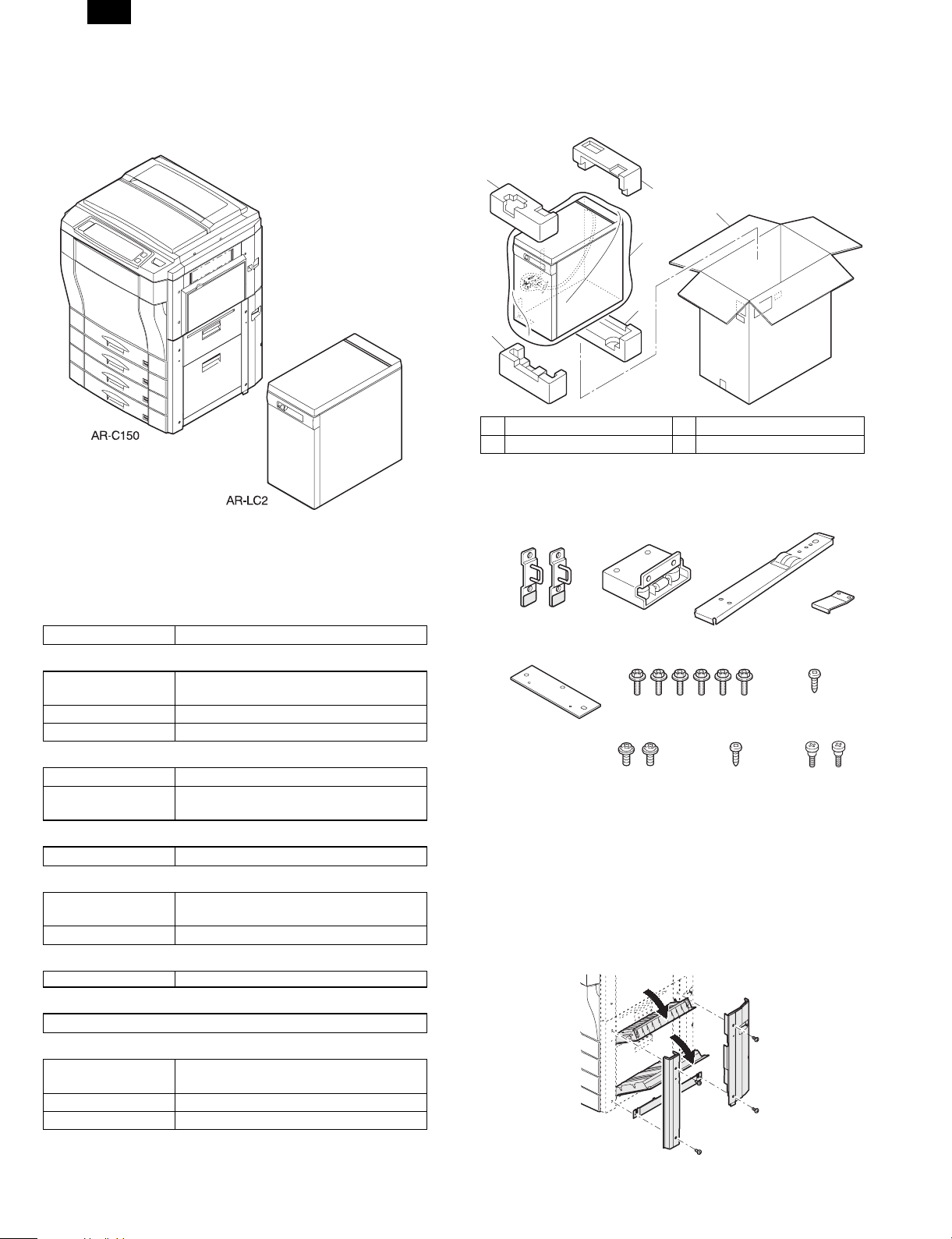
[1] OUTLINE OF THE PRODUCT
This paper feed unit stores about 3,300 sheets of A4 or letter size paper
to save the trouble of adding paper when a large amount of copies is to
be mode.
[3] UNPACKING AND INSTALLATION
1. Unpacking
1
1
4
2
3
3
1 Upper cushion 2 LCC
3 Lower cushion 4 Packing case
2. Installation procedure
Parts included
[2] SPECIFICATIONS
(1) Paper feed capacity
Paper feed capacity 3,300 sheets (64g/m2 or equivalent)
(2) Amount detection
Paper amount
detection
Detector 0% (empty), - 25%, - 50%, - 75%, - 100%
Paper size detection None
(3) Paper size
Paper size A4/Letter
Paper weight 60 to 105 g/m2 (14 to 28 lbs) (Same as the
(4) Size detection
Size detection Setting by simulation
(5) Factory setting
Factory setting paper
size
Plate display A4/Letter
(6) Power supply
Power supply supplied by the copier (DC5V, DC24V)
(7) Power consum pt i on
Not more than 30 W
(8) Externa l view
External dimensions 325 (Width) x 536 (Depth) x 595 (Height)
Weight about 32 kg
Case color Frosty gray
Provided (5-stage sensors including empty
detection)
copier’s paper feed section)
A4/Letter
mm
Upper mounting plates
(2 pcs.)
Option mounting plate
(1 pc.)
Mounting plate
(1 pc.)
Securing screws A
Securing screws C
(2 pcs.)
Connecting plate
(6 pcs.)
Securing screw D
(1 pc.)
(1 pc.)
Securing plate
(1 pc.)
Securing screw B
(1 pc.)
Step screws
(2 pcs.)
Unplug the power cord from the copier and then
follow the procedure below.
1. Remo ve the right cover.
1) Open the upper right door unit and the lower right door unit.
2) Unscrew the front right lower door.
3) Unscrew the rear right lower door, and remove the right lower
door.
1 – 1
Page 3

AR-LC2
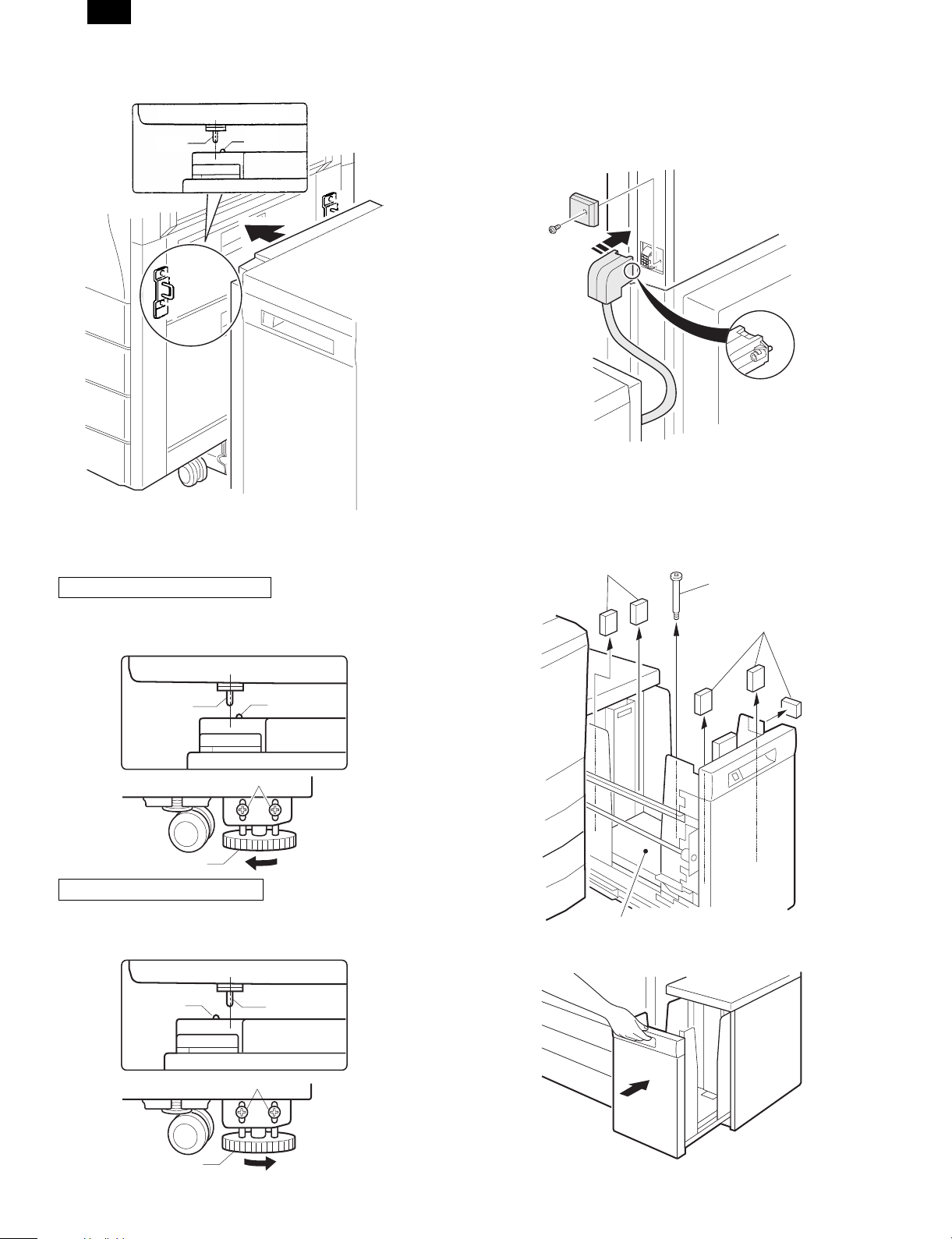
2. Instal l the option mounting plat e.
1) Install the option mounti ng plate.
2) Attach the right cabinet.
The convex side
is inside.
Step screws
Securing
screws D
Step screws
3. Install the upper mounting plates and the mounting
plate.
Make mounting holes with a driver, etc.
3) Remove the two pawls on the LCC cover, and detach the LCC
cover.
4. Mount the connecting plate to the larg e capacity tray.
NOTE: Before mounting the connecting plate to the large capacity tray,
be sure to remove the 2 step screws for securing the bottom plate.
Fit the connecting plate to the lower part of the large capacity tray and
mount the plate to the position indicated with A using screw B.
Securing screws B
Step screws
The spring is
provided only
for 200 series
models.
Connection
plate
Fit screws in hole A
5. Fit the connecting plate of the large capacity tray to
the mounting plate of the stand.
Insert the connecting plate into the mounting plate of the stand slightly
while lifting the large capacity tray.
After insertion, move the large capacity tray away from the copier to
check that the tray is locked.
While the tray is locked, mount the securing plate using screws C (2).
Securing
screws A
Rubber is attached
to the lower side.
Securing
screws A
1) Fit the upper mounting plates with the securing screws A (two for
each).
2) Fit the mounting plate to the lower part of the stand with the two
securing screws A.
Mounting plate
1
Securing
plate
Connecting
plate
2
Securing
plate
screw C
6. Check and adjust the heigh t of the large capacity tra y.
Move the large capacity tray toward the copier and adjust the tray and
check it so that the rib of the large capacity tray is flush with the axis of
the mounting plate which has been mounted to the copier as shown in
the figure.
LCC cover
3 – 1
Page 4
AR-LC2
•
When the axis is flush with the rib:
Push the large capacity tray toward the copier.
Top view
RibAxis
•
When the axis is not flush with the rib:
Loosen the two screws of the installation adjuster mounting plate located
at the lower part of the large capacity tray and adjust as follows:
★ When the rib is to the right of the axis
Turn the knob clockwise to adjust.
After adjustment, tighten the two screws of the installation adjuster
mounting plate.
Top view
7. Connect the connector of the large cap acity tray.
Remove the connector cover securing screw for connection of the large
capacity tray relay harness connector and remove the connector cover.
Then connect the large capacity tray relay harness connector to the
connector of the copier and tighten the screw on the connector to secure
the connector.
8. Remove the feed table securing screw and securing
materials.
Pull out gently the paper tray of the large capacity tray until it stops.
Remove the feed table securing screw and 5 securing materials which
secure the feed table of the large capacity tray.
Securing materials
Feed table
securing
screw
Securing materials
RibAxis
Securing screws
Knob
★ When the rib is to the left of the axis
Turn the knob counterclockwise to adjust.
After adjustment, tighten the two screws of the installation adjuster
mounting plate.
Top view
AxisRib
Securing screws
Feed table
Push back gently the paper tray to its original position.
Knob
3 – 2
Page 5
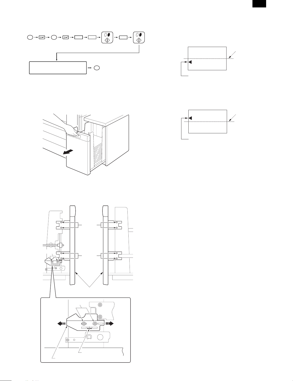
9. Set the mode.
•
Set the mode with the key operation of the copier.
PC
Clear
26
AR-LC2
•
In case of Fig. 1:
Move the tray lock plate in direction A by the length of displacement,
tighten the 2 screws at portion a and then the 8 screws at portion b, and
1
make a copy again to check that the center is not displaced.
Fig. 1
Center line of paper
Press the corresponding
operation key on the display.
CA
The mode is set with the
above operations.
10. Adjust the center position.
Since adjustment has been made at shipment, adjustment is basically
not needed. However, if the center should be displaced, adjust it using
the procedure below.
Make a copy. If the center is displaced as shown in Fig. 1 or Fig. 2, pull
out gently the paper tray until it stops.
Then, loosen the 2 screws at portion a which secure the tray lock plate
and the 8 screws at portion b (right and left sides) which secure the tray
cover unit to the frame and adjust the center position using the procedure
below.
Left side
Right side
Center of image (first image)
•
In case of Fig. 2:
Move the tray lock plate in direction B by the length of displacement,
tighten the 2 screws at portion a and then the 8 screws at portion b, and
make a copy again to check that the center is not displaced.
Fig. 2
Center line of paper
Center of image (first image)
Portion a
Direction A
Portion b
Portion b
Tray cover unit
Portion a
Direction B
Scale (pitch in mm)
Tray lock plate
3 – 3
Page 6
AR-LC2
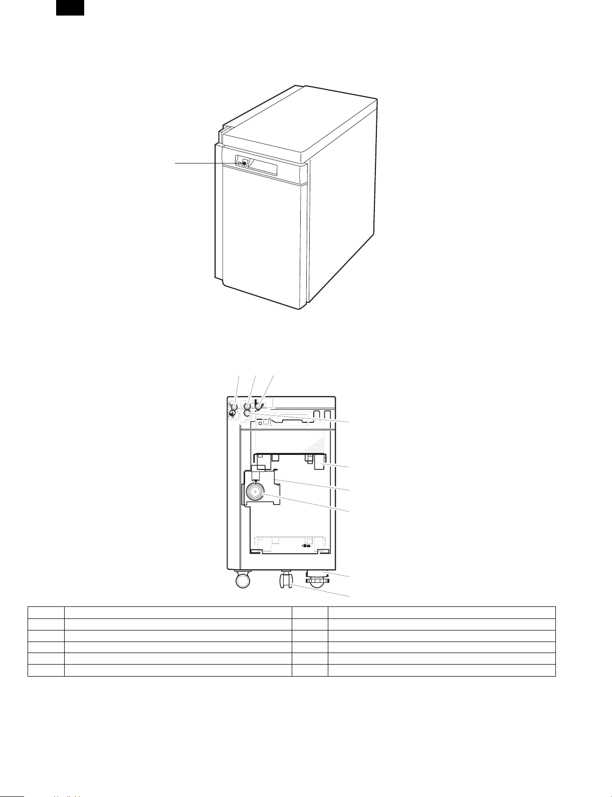
[4] EXTERNAL VIEW AND INTERNAL CONSTRUCTION
1. External view
1
1. Tray down/button/lamp
The tray can be opened by pressing the button. Use this button when adding paper or when a paper jam occurs.
2. Main parts
123
4
5
6
7
8
9
No. Name No. Name
1 Transport roller 6 Lift-up unit
2 Paper feed roller 7 Encoder
3 Pick-up roller 8 Height adjustment unit
4 Reversion roller 9 Caster
5 Tray
4 – 1
Page 7
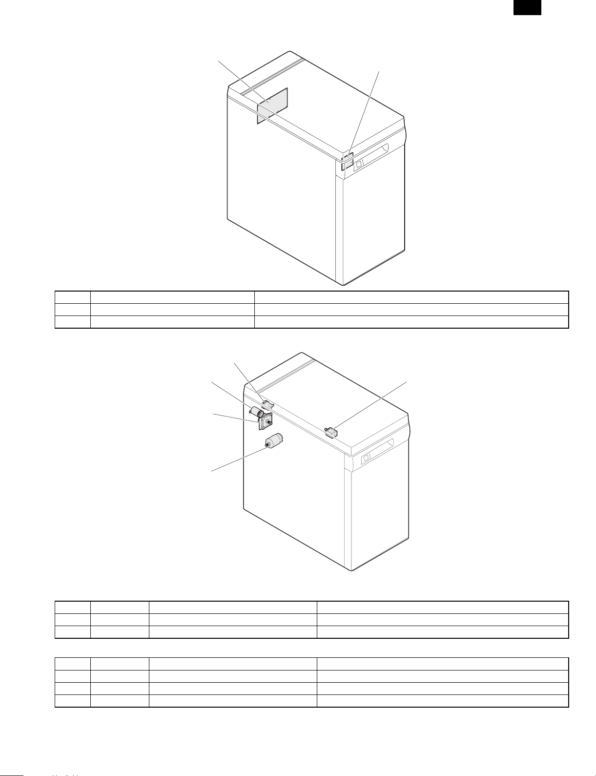
PWB location
AR-LC2
1
No. Name Function and operation
1 Control PWB Controlling LCC
2 Tray switch PWB Tray lifting switch
2
Motor, clutch, solenoid
3 LPFC
5 LTRC
4 LPFS
1 LPFM
2 LLM
Motor
No. Symbol Name Function and operation
1 LPFM Paper feed and transport motor Driving paper feed and transport systems
2 LLM Lift-up motor Driving tray lifting up
Clutch and solenoid
No. Symbol Name Function and operation
3 LPFC Paper clutch Driving paper clutch
4 LPFS Pick-up solenoid Operating pick-up roller
5 LTRC Paper feed clutch Driving paper clutch
4 – 2
Page 8

AR-LC2
Sensor, detector location
2 LLSW
4 LUD
3 LPED
1 LPFD
7 LTOD
5 LRES
6 LDD
No. Symbol Name Function and operation
1 LPFD Transport detector Detecting paper discharge
2 LLSW Upper limit lock switch Detecting tray upper limit lock (Shutting off motor as a safety device.)
3 LPED Paper detector Detecting the presence of paper
4 LUD Upper limit detector Detecting tray upper limit position
5 LRES Encoder sensor Controlling lifting up
6 LDD Lower limit detector Detecting tray lower limit position
7 LTOD Copier connection detector Detecting connection to copier
4 – 3
Page 9

AR-LC2
[6] DISASSEMBLY AND ASSEMBLY
1. Transport section (Paper feed roller)
2)
3)
4)
6)
5)
2)
7)
5)
1)
1)
2. P aper feed section
A. Paper feed unit
2)
1)
2)
2)
3)
1)
2)
6 – 1
Page 10

AR-LC2
B. Paper feed roller, take-up roller
2
2)
1)
C. Reverse roller
2)
3)
1)
1
[ a ]
3)
6)
4)
5)
NOTE: 1. When installing the paper feed roller , take car e of the
installing direction.*1
(The rib o f the pa per feed roller must be set toward th e rear
frame.)
2. When install ing the paper feed clutch , check that the cl utch
stopper is caught by the pawl.*2
6)
3. Control PWB
6 – 2
Page 11

AR-LC2
4. Paper feed/transport motor
3)
2)
5. Lift-up motor
6. Clutch
1)
2)
2)
1)
3)
2)
6 – 3
Page 12

AR-LC2
[10] WIRING DIAGRAM
Copier
LRE
LDD
TRAY SW
PWB
LIFT
MOTO
CN-11
1
2
3
CN-12
1
2
3
BL
BR
GY
BL
PL
GY
CN-13
GY
3
LB
2
BR
1
CN-14
RD
1
GY
2
PK
3
G8
GY GY
G4 G3
CN-15
LTRC
CN-RL
WH
CN-HT
WH
CN-DT 12pin
1
2
6
11
3
7
8
9
10
4
5
12
2
1
12
12
LHT
WH
WH
CN-A
BL
22 5V(LRE)
BR
24 LRE/
GY
26 GND2(LRE)
BL
21 5V(LDD)
PL
23 LDD
GY
25 GND2(LDD)
PK
28 LCD/
LB
27 LDSW/
BR
29 LLED
RD
3 LLM+
PK
4 LLM-
CN-D
RD
1 24V(LTRC)
BR
2 LTRC/
G1
LCC
CONTROL
PWB
83
BR
1
PLLBBR
2
4
TXD-LCC
RXD-LCC
DSR-LCC
CN-B
PKRDGY
3
5
DTR-LCC
RES-LCC
91051112467
BL
GY
75V8
9
10
24V
GND2
GND1
CN-A
CN-C
BL
95V(LUD)
BR
11LUD/
GY
13GND2(LUD)
BL
105V(LPED)
PL
12LPED/
GY
14GND2(LPED)
RD
124Vout
RD
224V(LLSW)
RD
524V(LPFC)
PK
6LPFC/
RD
724V(LPFS)
LB
8LPFS/
BL
155V(LPFD)
BR
17LPFD/
GY
19GND2(LPFD)
BL
165V(LTOD)
BR
18LTOD/
GY
20GND2(LTO)
BL
15V
BR
2RE
PL
3HU
LB
4HV
PK
5HW
GY
6GND1
PL
7U
LB
8V
PK
9W
1
2
3
4
5
6
7
8
9
10
11
12
CN-FT 3pin
1
2
3
CN-3CN-KT 12pin
3
2
LUD
1
CN-4
3
2
LPED
1
LLSW
CN-1 CN-2
CN-5
1
2
CN-6
1
2
CN-7
1
3
2
CN-8
1
2
3
LPFC
LPFS
LPFD
LTOD
CN-10
4
6
3
2
1
5
9
8
7
LPFM
10 – 1
Page 13

Control circuit
Block diagram
AR-LC2
Copier
VCC
GND2
+24V
GND1
FG
RXDTXDDSRDTRRES-
Communication
buffer circuit
8MHz
Xtal
Power supply
monitoring unit
24V
Power supply
10 V circuit
10V
CPU(H8/3294)
Operation unit
Large-capacity tray control PWB
Large-capacity tray
24V
Lift motor drive
circuit
Clutch solenoid
drive circuit
LED lighting circuit
Sensor input
circuit
Transfer motor
drive circuit
10V
Upper limit sw (LLSW)
Lift motor (LLM)
Paper amount detection
sensor (LRE)
Paper feed clutch (LPFC)
Transport clutch (LTRC)
Paper feed solenoid (LPFS)
LLED
Cassette detection line (LCD)
Upper limit detection sensor (LUD)
Lower limit detection sensor (LDD)
Paper detection sensor (LPED)
Paper delivery detection sensor
(LPFD)
Copier connection sensor
Door open switch (LDSW)
Transfer motor (LPFM)
10 – 2
Page 14

AR-LC2
[11] EXPLANATION OF THE CIRCUITS
A
CN-A-21
220(1/4W)
220(1/4W)
R97
2 1
11
10
IC12F
IC12G
TD62504F
6
TD62504F
7
R
4.7K
+5V
=
R
3
C16
C13
C12C10 C11
LLED/
VCC
N.C
N.C
N.C
PWM/
DIR
RE
N.C
SW2
VCC
N.C
SW1-4
SW1-3
SW1-2
SW1-1
1000P X5
B
CN-A-29
LLED
R03
220(1/4W)
+5V
IC12E
TD62504F
512
R02
2.2K
+5V
2-C2
2-B2
2-B2
PWM/
DIR
RE
+5V
R52
R51
R75
R50
R49
R48
R47
R46
R45
R44
4.7K X 10
CN-A-15
R96
+5V
D
CN-A-6
Q2
DTD114GK
R91
R04
CN-A-8
LPFS/
LPFC/
16
15
ULN2004A
E
IC04A
IC04B
1
2
LPFC
LPFC
LPFSLPFS
10K
10K
R89
R93
22K
22K
R92
4.7K
R05
4.7K
CN-D-2
LTRC/
12345678
+24V
D1
1SS133
Q3
C
B
DTD114EK
C
10k
B
E
+24V
LLMD
LLMU
2-C2
2-C2
LLMD
LLMU
ULN2004A
+5V
R61
R63
R66
R65
R64
R62
C
CN-A-28
CN-A-11
CN-A-18
CN-A-27
1000P X2
+5V
R78
4.7K X 4
R54
R74
R73
R72
LPFC
N.C
N.C
LLMU
LPFS
N.C
LLMD
N.C
48
40
47
P10/A0
P17/A741P16/A642P15/A543P14/A444P13/A345P12/A246P11/A1
P50/TXD
P51/RXD2P52/SCK3/RES4/NMI5VCC6/STBY7VSS8XTAL9EXTAL10MD111MD012AVSS13P70/AN014P71/AN1
1
/NMI
VCC
XTAL
/STBY
TXD-LCC
RES-LCC
DSR-LCC
RXD-LCC
CN-A-12
LUD
LDSW
LPED
65432
BR04
10K
10K
R81
R82
LDSW
LPFD
LDD
LCD1
LTO D
LUD
LPED
33
37
39
VSS
P21/A938P20/A8
P25/A1334P24/A1235P23/A1136P22/A10
P67/TMO1
P66/FTOB/TMRI1
P65/FTID/TMCI1
P64/FTIC/TMO0
P63/FTIB/TMRI0
P62/FTIA
P61/FTOA
P60/FTCI/TMCI0
P77/AN7
P76/AN6
P75/AN5
P74/AN4
P73/AN3
16
15
N.C
N.C
N.C
MD1
MD0
AVSS
EXTAL
R41
R42
R43
LTO D
4.7K X 5
10K
R83
P26/A14
P27/A15
AVCC
P72/AN2
VCC
4.7K X 3
LCD1
10K
10K
R84
32
31
30
29
28
27
26
25
24
23
22
21
20
19
18
17
CN-A-17
CN-A-23
LDD
LPFD
1SS133
D23
R95
22K
22K
R94
R79
R59
R58
R57
R56
R55
LCD2
/24VM
DTR-LCCDTR-LCC
YOB I
10K
R80
4.7K X 11
N.C
N.C
N.C
N.C
N.C
N.C
N.C
LRELRE
N.C
N.C
N.C
N.C
D24
C15
C14
10K
49
P30/D0
50
P31/D1
51
P32/D2
52
P33/D3
53
P34/D4
54
P35/D5
55
P36/D6
56
P37/D7
57
P40//ADTRG//IRG
58
P41//IRQ1
59
P42//IRQ0
60
P43//RD
61
P44//WR
62
P45//AS
63
P46/CLK
64
P47//WAIT
IC01
H8/3294 FP-64A
1SS133
MAIN PWB
0.1U
C09
6785243
+5V
+5V
D01 D02 D03
+5V
D
O314O215O116O413O710O512O6
I33I22I11I44I77I55I6
IC02
6785243
1SS133x6
TXD-LCC
CN-B-1
BR02
4.7KX7
11
9
NC
GND
TD62504F
6
8
BR01
4.7KX7
+5V
D07 D08
0.1U
C35
0.1U
C05
D05
D04 D06
DTR-LCC/
LRE/
RES-LCC/
CN-B-3
CN-B-5
CN-A-24
C
0.1U
10K
R01
C08
47U
+
C07
+5V
CN-C-1
CN-A-13
CN-A-19
CN-A-5
CN-A-7
CN-A-9
CN-A-10
CN-A-16
X1 8.00MHz
1SS133x2
D10
D09
1SS133x2
DSR-LCC/
RXD-LCC/
CN-B-2
CN-B-4
+24V
CN-A-1
+24V
+24OUT
+24V
+24V
CN-B-09
CN-A-22
+5V
+5V
0.1U
C02
47U/35V
+
C01
GND1
+5V
+5V
GND1
CN-B-7
CN-B-10
B
CN-A-20
CN-A-25
CN-A-14
CN-A-26
CN-C-6
0.1U
C04
+
47U/35V
C03
GND2
GND2
CN-B-8
+24V(LLSW)
+24V(LLSW)
CN-A-2
CN-B-6
8 7 6 5 4
A
11 – 1
Page 15

AR-LC2
D
C
B
A
12345678
CN-C-7
CN-C-8
CN-C-9
V
U
W
1OA3OB7
VCC
9
1K x3
2.2K
ULN2004A
IC04F
D17 D18 D19
10
OC
GND5GND12IC211IB26IA2
BR08
ULN2004A
611
432
680
R23
ISR124-400 X3
0.1U
C34
1
IC09A
LM393
8
4
+
-
+10V
3
SLA6012
4
C22 C23 C24
0.1U X3
1K x3
680
680
R24
R25
10
ULN2004A
IC04G
7
2
C27
+5V
R27
2.4K
0.1U
360
R29
200
R28
/1W
R26
0.22
C26
0.1U
+24V(LLSW)
CN-A-3
CN-A-4
LLM+
LLM-
0.1uF
C31
F01
1.25A/120V
T1.0A/250V
IC07
STA457C
7
2
R36 1K
3
7
2
116
(1/4W)
R40
3.9K
R39
10K
R38
10K
9944883
10
10
5
5
6
1K
R37
1SS133x2
D21
D20
2 1
3
+24V
+
IC06
BR07
IC04E
C25
100U/35V
IA12IB18IC1
234
2.2K
2.2K
R20
R21
R22
512
TD62504F
TD62504F
215
IC12C
314
TD62504F
+5V
R15
R14
2.2K
2.2K
+5V
R86
10K
10K
10K
R16
R17
R18
OUT111OUT312OUT513OUT614OUT415OUT2
IN11IN22IN34IN43IN55IN66VCC8VREF
IC05
234
1.2K
1.2K
R88
R87
16
BR15
+5V
1.2K
7
9
GND
REVERSE
10
+10V
2.2K X 3
DIR
UPC1246C
0.1U
C21
RE
R76
R85
2.2K
1000P X4
IC12D
1-D2
1-D2
10K
413
R77
PWM
TD62504F
10K
1-D2
+24V
+24V
R90
1K(1/4W)
IC12A
IC12B
116
+10V
R19
2.7K
FR01
R32
IC04C
1-E4
100(1/4W)
1K(1/4W)
R34 1K
ULN2004A
314
LLMU
Q02
2SC1472K
R35 1K
IC04D
413
+10V
C30
C29
D22
RD11EB
LLMD
D25
0.1U
0.1U
ULN2004A
1-E4
RD18FB1
7
IC09B
LM393
+
-
5
6
IC12
IC04
9
+24V
8
9
N.C
8
MAIN PWB
D
C18 C20
C17 C19
8 7 6 5 4
HV
HU
RE/
HW
CN-C-3
CN-C-4
CN-C-5
CN-C-2
C
B
11 – 2
A
Page 16

AR-LC2
D
C
B
A
12345678
1
2
24V
LTRC/
CN-D (B2B-PH-K-S)
1
2
3
4
5
6
7
8
9
2 1
3
5V
RE/HUHVHWGND2UV
CN-C (B9B-EH-A)
W
RXD-LCC
DSR-LCC
GND2
GND2
123456789
TXD-LCC
DTR-LCC
RES-LCC5V24V
24V(LLSW)
LLM-
LPFC/
LPFS/
2
65
87
1
34
GND1
10
5V(LPED)
LPED/
109
12
11
GND2(LPED)
5V(LTOD)
LTOD/
GND2(LTOD)
5V(LRE)
LRE/
GND2(LRE)
LCD1/
LCD2/
1615
2019
2423
2827
13 14
17 18
21 22
25 26
29 30
CN-A (B30B-PHDSS) CN-B (B10B-PHDSS)
MAIN PWB
D
24V(OUT)
LLM+
24V(LPFC)
24V(LPFS)
5V(LUD)
LUD/
GND2(LUD)
5V(LPFD)
LPFD/
GND2(LPFD)
5V(LDD)
LDD/
GND2(LDD)
LDSW/
LLED/
C
B
A
8 7 6 5 4
11 – 3
Page 17

[Note]
The AR-LC2 Parts guide describes only the
different points from the AR-LC1. Please
refer to the AR-LC1 Parts guide as well.
AR-LC2
PARTS GUIDE
MODEL AR-LC2
CONTENTS
1 Exteriors
2 Frame 1
3 Frame 2
4 Frame 3
5 Paper feeding section(Refer to the AR-LC1 Parts guide)
6 Drive section(Refer to the AR-LC1 Parts guide)
7 Transport section
8 Packing materials & Accessories
SHARP CORPORATION
This document has been published to be
used for after sales service only.
The contents are subject to change without
notice.
Page 18

AR-LC2
DEFINITION
The definition of each Rank is as follows and also noted in the lis t
A : Parts necessary to be stocked as High usage parts.
B : Parts necessary to be stocked as Standard usage parts.
C : Low usage parts.
D : Parts necessary for refurbish.
E : Unit parts recommended to be stocked for efficient after sales service.
Please note that the lead time for the said parts may be longer than normal parts.
S : Consumable parts.
Please note that the following parts used in Copier under the same description are classi fied into A or B Rank depending
upon the place used.
Example : Gear made of Metal, Sprocket, Beari ng, Belt made of Rubber, Spring clutch mechanism.
A Rank : The parts which may be with the revolution or loadi ng.
B Rank : Parts similar to A Rank parts, but are not included in Rank A.
Because parts marked with "!" is indispensable for the machine safety maintenance and operati on, it must be replaced with
the parts specific to the product specification.
F Other than this Parts Guide, please refer to documents Service Manual (including Circuit Diagram) of this model.
F Please use the 13 digit code described in the right hand corner of front cover of the document, when you place an order.
F For U.S. only-Use order codes provided in advertising literature. Do not order from parts department.
1Exteriors
PRICE
NEW
NO. PARTS CODE
0EUCOV0402E22 BA
3
RANK
PART
MARK
RANK
N C Tray cabinet
DESCRIPTION
2 Frame 1
NO. PARTS CODE
0EUSLI0601K// BA
11
0EUPLT0472N// AG
26
0EUPLT0473N// AG
27
0EUSFT0480N// AN
29
0EUSTY0416K02 BC
33
0EUANG0459N// AM
34
XHBSE40P08000 AA
45
3 Frame 2
NO. PARTS CODE
0EUSTY0405E03 BG
18
0EUANG0458N// AK
37
0EUPWB0409N31 BS
42
0EUPWB0409N32 BS
0EUHAI0450N// BA
43
0EUANG0457N// AL
67
0EUSFT0481N// AL
68
PCLC-0270FCZZ AW
69
NGERH0853FCZZ AE
70
NGERH1174FCZZ AQ
71
0EUHAI0451N// AG
72
XHBSE40P08000 AA
73
LPINS0155FCZZ AA
74
NBRGC0504FCZZ AC
75
XBBSD40P08000 AA
76
PRICE
RANK
PRICE
RANK
NEW
PART
MARK
RANK
N C Slide rail
N C Adjust guide plate F
N C Adjust guide plate R
N C Adjust screw
N C Caster plate
N C Caster
CScrew (4´8)
NEW
PART
MARK
RANK
N C Stay
N C Drive plate
N E LCC Main PWB unit 100V
N E LCC Main PWB unit 200V
N C I/F harness
N C CL plate
N C CL shaft
C Electromagnetic cluch (22T)
C Gear (32T)
C One way gear (17/22T)
N C CL I/F harness
CScrew (4´8)
C Pin (3-10)
C Bearing (F8-12-5)
CScrew (4´8)
DESCRIPTION
DESCRIPTION
4 Frame 3
NO. PARTS CODE
0EUSFT0482N// AW
18
0EULEG0606N// AT
46
0EUNZ-0603J// AE
51
XWHSD80-16180 AA
52
XBBSD30P08000 AA
53
7 Transport section
NO. PARTS CODE
0EUROL0360N// AV
4
0EUSPR0476N// AD
6
0EUGER0423N01 AN
9
PRICE
RANK
PRICE
RANK
NEW
PART
MARK
RANK
N C LCC rear edge guide
N C Caster
CNut M8
C Washer
CScrew (3´8)
NEW
PART
MARK
RANK
N C Transfer roller
N C Transfer spring 2
N C Gear 18T
– 1 –
DESCRIPTION
DESCRIPTION
Page 19

8 Packing materials & Accessories
PRICE
NEW
NO. PARTS CODE
0EUPKC0675N// AY
8
LPLTM5517FCZZ AE
17
LX-BZ0408FCZZ AB
18
XHBSE40P08000 AA
19
RANK
PART
MARK
RANK
N C Packing case
N C Option fixing plate
CScrew
CScrew (4´8)
2 Frame 1 3 Frame 2
AR-LC2
DESCRIPTION
34
4 Frame 3
45
45
33
53
53
73
53
67
74
18
75
68
31
44
69
4
33
5
4
44
71
44
34
33
44
36
4
5
35
76
70
4
37
73
4
33
5
36
42
64
41
18
44
44
51
52
45
46
8 Packing materials & Accessories
17
18
19
FCP03704
– 2 –
Page 20

AR-LC2
Page 21

CAUTION FOR BATTERY REPLACEMENT
(Danish)
Lithiumbatteri – Eksplosionsfare ved fejlagtig håndtering.
Udskiftning må kun ske med batteri
Levér det brugte batteri tilbage til leverandoren.
(English)
Danger of explosion if battery is incorrectly replaced.
Replace only with the same or equivalent type
recommended by the manufacturer.
Dispose of used batteries according to manufacturer’s instructions.
(Finnish)
Paristo voi räjähtää, jos se on virheellisesti asennettu.
Vaihda paristo ainoastaan laitevalmistajan suosittelemaan
tyyppiin. Hävitä käytetty paristo valmistajan ohjeiden
(French)
Il y a danger d’explosion s’ il y a remplacement incorrect
de la batterie. Remplacer uniquement avec une batterie du
même type ou d’un type équivalent recommandé par
Mettre au rebut les batteries usagées conformément aux
(Swedish)
Explosionsfara vid felaktigt batteribyte.
Använd samma batterityp eller en ekvivalent
typ som rekommenderas av apparattillverkaren.
Kassera använt batteri enligt fabrikantens
ADVARSEL !
af samme fabrikat og type.
Caution !
VAROITUS
mukaisesti.
ATTENTION
le constructeur.
instructions du fabricant.
VARNING
instruktion.
AR-LC2
Page 22

AR-LC2
All rights reserved.
Printed in Japan.
No part of this publication may be reproduced,
stored in a retrieval system, or transmitted,
in any form or by any means,
electronic; mechanical; photocopying; recording or otherwise
without prior written permission of the publisher.
SHARP CORPORATION
Digital Document Systems Group
Quality & Reliability Control Center
Yamatokoriyama, Nara 639-1186, Japan
1999 September Printed in Japan
 Loading...