

Page 1

CODE: 00ZARFN4//A1E
DIGITAL COPIER OPTION
FINISHER
MODEL AR-FN4
CONTENTS
[ 1 ] INTRODUCTION . . . . . . . . . . . . . . . . . . . . . . . . . . . . . . . . . . . . 1-1
[ 2 ] UNPACKING AND INSTALLATION . . . . . . . . . . . . . . . . . . . . . 2-1
[ 3 ] OPERATIONAL DESCRIPTIONS . . . . . . . . . . . . . . . . . . . . . . . 3-1
[ 4 ] DISASSEMBLE AND ASSEMBLE . . . . . . . . . . . . . . . . . . . . . . 4-1
[ 5 ] MAINTENANCE . . . . . . . . . . . . . . . . . . . . . . . . . . . . . . . . . . . . . 4-9
[ 6 ] ADJUSTMENT . . . . . . . . . . . . . . . . . . . . . . . . . . . . . . . . . . . . . . 6-1
[ 7 ] TROUBLESHOOTING . . . . . . . . . . . . . . . . . . . . . . . . . . . . . . . . 7-1
[ 8 ] SELF TEST MODE . . . . . . . . . . . . . . . . . . . . . . . . . . . . . . . . . . 8-1
[ 9 ] ELECTRICAL SECTION . . . . . . . . . . . . . . . . . . . . . . . . . . . . . . 9-1
[10] ACTUAL WIRING CHART . . . . . . . . . . . . . . . . . . . . . . . . . . . . 10-1
This document has been published to be used
for after sales service only.
The contents are subject to change without notice.
Page 2

[1] INTRODUCTION
1. Features
1) Compact, light-weight
2) Mono-cock frame
Mono-cock frame reduces the number of covers.
3) Bundle offset sorting/stapling
Paper bundle is made and aligned on the intermediate process
tray to allow bundle offset/stapling.
4) Stack tray
The max. load capacity of the stack tray is 1,000 pages (small
size) or 500 pages (large size).
Fifty stapled bundles (max. 20 pages) can be loaded on the tray.
∗1: Small size: A4, A4R, A5, A5R, B5, B5R, LTR, LTRR
∗2: Middle size: B4 LGL, 8.5" x 13", 8.5" x 14"
∗3: Large size: A3W, A3, 12" x 18", LDR
∗4: The total number of pages must be within the specified range of
numbering.
∗5: Alignable width: Alignable paper width in the backward/forward
direction
∗6: Offset width: Shift of paper bundle when sorting
45
2.5mm
5
2. Specifications
A. Specifications
Item Content
Stack system Stack tray: Tray lift system (Intermediate process
Loading direction Face down loading
Loading
paper size
Paper
weight
Bin number Stack tray 1
Kinds of mode Staple loading
Stack tray
loading
capacity
Alignable
width ∗5
Alignable size A3W, A3, A4, A4R, A5, B4, B5
Staplable size A3W, A3, A4, A4R, A5, B4, B5
Offset width ∗6 20mm
Binding system Punching by the rotational cam
Binding position One at a corner, slant binding (Refer to Fig. 1-101.)
Binding capacity Small size Max. 20 pages 80g/m
Stapler loading system Cartridge (3,000 staples)
Applicable stapler Specified stapler
Stapler empty detection YES
Manual stapling NO
Paper detection YES
Operation panel NO (Operated by the copier.)
Display NO (Displayed on the copier.)
Dimensions (W x D x H) 515mm x 574mm x 381mm (Except for the
Weight About 17kg (without the installing kit)
Power source 24V (Supplied from the copier)
Max. power consumption About 60W
AB series A3W, A3, A4, A4R, A5, A5R, B4, B5, B5R, A6R
Inch series LDR, LGL, LTR, LTRR, 7.25" x 10.5"R, 8.5" x 13",
Face-up 60g/m
Face-down 64 – 128g/m
Non binding Small size 1000 pages 80g/m
Staple sort Small size ∗1 20-page bundle
Non binding 139.7mm – 297mm
Staple 210mm – 297mm (A5: Not staple)
tray fixed)
Face up loading (1 to N)
8.5" x 5.5", 8.5" x 5.5"R, 12" x 18"
2
– 200g/m
Intermediate process tray 1
Non-staple loading
Non-staple bundle offset loading
Middle size 700 pages
Large size 500 pages
Middle size ∗2 20-page bundle
Large size ∗3 15-page bundle
12" x 18", LDR, LGL, LTR, LTRR, 8.5" x 5.5",
8.5" x 13"
LDR, LGL, LTR, LTRR, 8.5" x 5.5", 8.5" x 13"
Middle size Max. 20 pages
Large size Max. 15 pages
installation kit)
About 23kg (with the installing kit)
2
2
equivalent
paper
(Max. 50 bundles)
(Max. 50 bundles)∗4
(Max. 50 bundles)∗4
equivalent
paper
2
2
or
or
5 2.5mm
Fig. 1-101 Binding position
• Cross section view
[1] Stack tray
Alignment plate (Backward/forward)
[2]
[3] Paper feed guide A
[4] Paper feed guide B
[5] Paper exit roller
[6] Paper path
[7] Return roller
[8] Stopper plate
• Top view
[1] Bundle exit belt
[2] Rear alignment plate
[3] Knob
[9] Staple unit
[10] Paper holding lever
[11] Bundle exit belt
[11A] Bundle exit lever
Intermediate process tray load guide plate
[11B]
[12] Intermediate process tray
[13] Frame
Fig. 1-102
[4] Stack extension tray
[5] Stack tray
[6] Front alignment plate
Fig .1-103
1 – 1
Page 3

AR-FN4 Installation Manual
FOR USE WITH COMPATIBLE SHARP COPIERS
SEE SHARP COPIER INSTALLATION MANUAL TO DETERMINE
SUITABILITY
[2] UNPACKING AND
INSTALLATION
1. Un pac king
(1) Unpacking and identification of parts
4
Remove the filament tape, and remove each packing.
Alignment plate cushion
2
1
15
14
12
11
: Fold on the side to indicate the filament tape side.
Tightening screws
3
5
6
7
2. Installation
(1) Open the split holes and the installation holes,
13
8
9
10
and attach the step screws.
• Tighten the step screws temporarily.
Cut off the six notch sections. (Cut off the two sections on the upper
left side of the cabinet with nippers, and break the four sections on
the lower side with a screwdriver as shown below.)
Tighten the step screw temporarily as shown in the figure and loosen
one turn.
Cut-out
Step screws
Step screw,
2pcs
1 Machine Pad B
2 Kit spacer U front
3 Kit fixing pawl
4 Latch plate U
5 Screws, latch plate spacers x2
6 Kit spacer U rear
7 Machine pad A
Installation kit (Set this kits after installing the installation kit
8
holding pad.)
Installation kit holding pad (Set between machine pads C and
9
D on the installation kit package.)
10 Machine pad C
11 Machine pad D
Cardboard box seal (Set between machine pads C and D after
12
installing the installation kit.)
13 Machine body
14 Kit cover U (with guide wire)
15 Knob blind cover U
Spacer,
2 pcs
M4 x 18,
4 pcs
Black screw
M4 x 25,
4 pcs
M4 x 6,
4 pcs
Cut-out
(2) Attach the latch holding plate.
Attach the latch holding plate to the split hole on the left cabinet of the
copier with the spacers.
(Screws M4 x 18, 2pcs; spacers, 2 pcs.)
2 – 1
Page 4
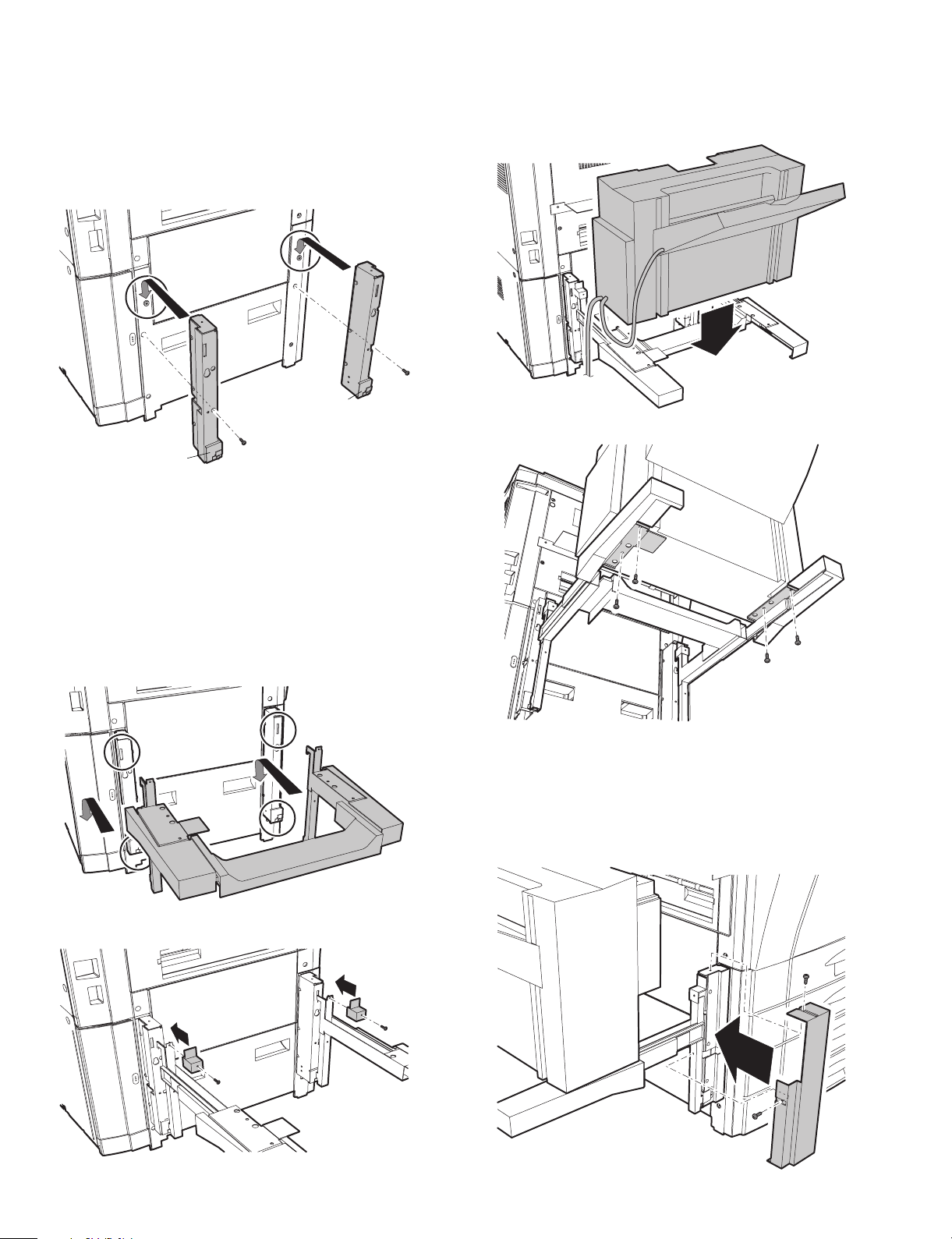
(3) Attach the kit spacers (F/R).
Hang the kit spacers (F/R) on the step screws, fix them through the
lower holes with screws, and tighten the step screws to secure. Then
rotate it one turn in the reverse direction.
• When fixing, press down the kit spacers as shown in the figure.
• Be careful of the direction of the kit spacers. There are marks of F
and R on the spacers.
(Screws M4 x 18, 2 pcs.)
F
R
(4) Attach the acuride rail unit.
Hang the frame of acuride rail unit on the lower projections of the
spacer kits, and hang the pawls of the acuride rail unit on the square
holes on the upper side of the kit spacers.
Insert the fixing pawls into the upper pawl section to fix.
• At that time, be careful not to deform the lower projection of the kit
spacer.
Also check that the lower projection and the upper projection are
securely held.
(Screws M4 x 6, 2 pcs.)
(5) Attach the finisher.
Slide the acuride rail unit completely to the left, and while aligning the
finisher to the positioning dowels, fix it in place at its lower side with
the four screws. (Black screws M4 x 25, 4 pcs.)
(6) Attach the kit cover.
Fit the kit cover to the kit spacer (F) and fix with two screws.
(Screws M4 x 6, 2 pcs.)
Fit the front cabinet of the reverse section with the kit cover surface.
(Screws M4 x 6, 2 pcs.)
Fit the upper and the lower lines of the cabinet.
2 – 2
Page 5
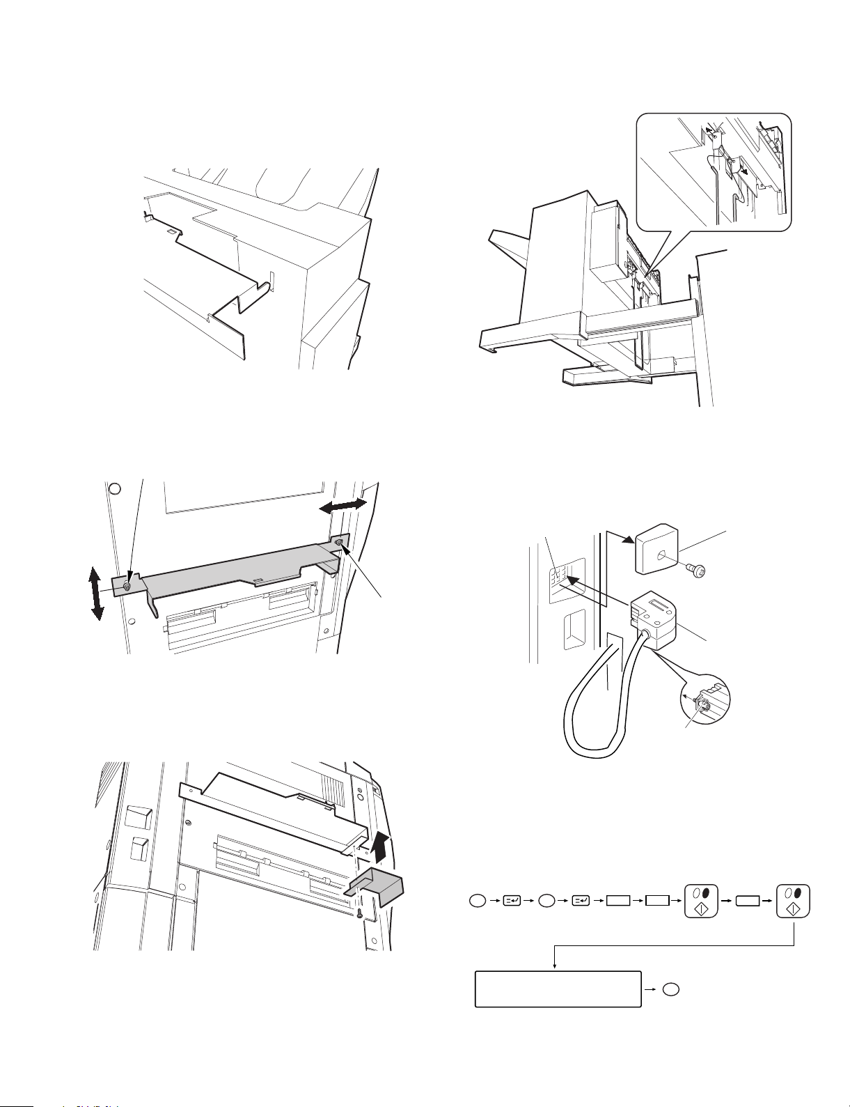
(7) Adjust the installing position of the latch
holding plate.
Slide the finisher to the right (in the locking direction). Adjust the
height with the screw on the rear side of the latch holding plate so
that the sensor contact section of the latch holding plate come at the
center of the sensor hole of the finisher.
Adjust the forward/backward position with the screw on the front side
of the latch holding plate so that the finisher is smoothly caught by the
lock of the latch holding plate.
Screw on
the rear side
(9) Attach the paper guide wire.
Insert the paper guide wire to the holding hole on the lower side of the
reverse section of the finisher.
(10) Connect the finisher connector.
Remove the finisher connector cover from the rear cabinet of the
copier.
Connect the finisher connector to copier’s connector, and tighten the
connector screw to fix.
Screw on
the front side
(8) Attach the blind cover.
While aligning the blind cover to the positioning dowls on the front
side of the latch holding plate, fix it in place at its lower side with the
screws.
Connector of the copier
Finisher connector cover
Finisher connector
Screw
(11) Set the mode
Set the mode with SIM 26.
Insert the power plug of the copier into the power outlet, turn on the
power switch, and follow the procedures below.
• Set the mode with the key operation ot the copier.
PC
Clear
26
1
2 – 3
Select the mode in the LCD
window.
CA
The mode is set with the
above operations.
Page 6
[3] OPERATIONAL DESCRIPTIONS
1) This chapter gives brief descriptions of the purpose and the role of
each function, the relationship between the electrical section and
the mechanical section, and the operating timing of each section.
The mark " " shows a mechanical transmission. If it is
togeth er with " " and a signal na me, it shows a flow of an
electric signal.
2) In the descriptions of the digital circuits in this chapter, "1" shows a
high voltage level of a signal, and "0" a low voltage level of a
signal. The voltage, however, differs in different circuits.
Though this machine employs a microprocessor, operational
descriptions on the microprocessor are omitted because it is virtually impossible to check inside the microprocessor.
Since the print PWB is not repaired by a user on principle, the
descriptions on the print PWB is limited to a brief one with block
diagrams. Therefore, the circuit descriptions of this chapter include
one from the sensor to the input section of the major PWB’s, one
from the output section of the major PWB’s to the load, and block
diagrams of each function.
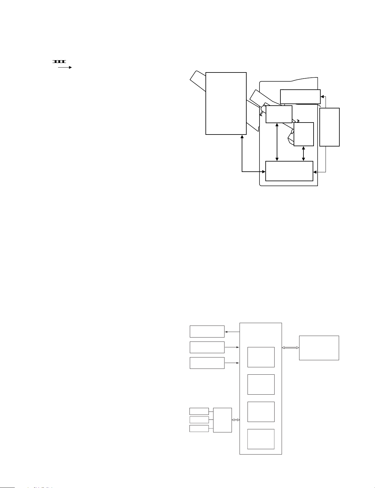
1. Basic composition
A. Outline
This machine is composed of the following five sections: the reverse
section, the paper exit section, the intermediate process tray section,
the stapler section, and the stack tray section. The figure below
shows the composition.
Paper exit section
Stack tray section
Intermediate
process tray
section
Stapler
section
Finisher controller
PWB
Fig. 3-101
B. Brief description of electric circuit
The operating sequence of the finisher is controlled by the finisher
controller PWB, which employs a 16 bit CPU to make sequence
control (and serial communication with the copier).
The finisher controller PWB drives the motor according to a command
sent from the copier through the serial communication line. It also
sends to the copier various information on the sensors and switches
through the serial communication line.
The major purposes of IC’s integrated in the finisher controller PWB
are as follows:
• IC1 (CPU)
Sequence control
• IC3 (EP-ROM)
Sequence program
• IC4 (Communication IC)
Communication with the copier (IPC II)
• IC12 (Regulator IC)
Generation of 5V for driving sensors and logics
Reverse
section
3 – 1
Motors
Sensors
Switches
Motors
Sensors
Solenoid
Reverse
drive
PWB
Finisher
controller
PWB
IC1
CPU
IC3
EP-ROM
IC4
Communication
IC
IC12
Regulator IC
Fig. 3-102
Copier
Page 7
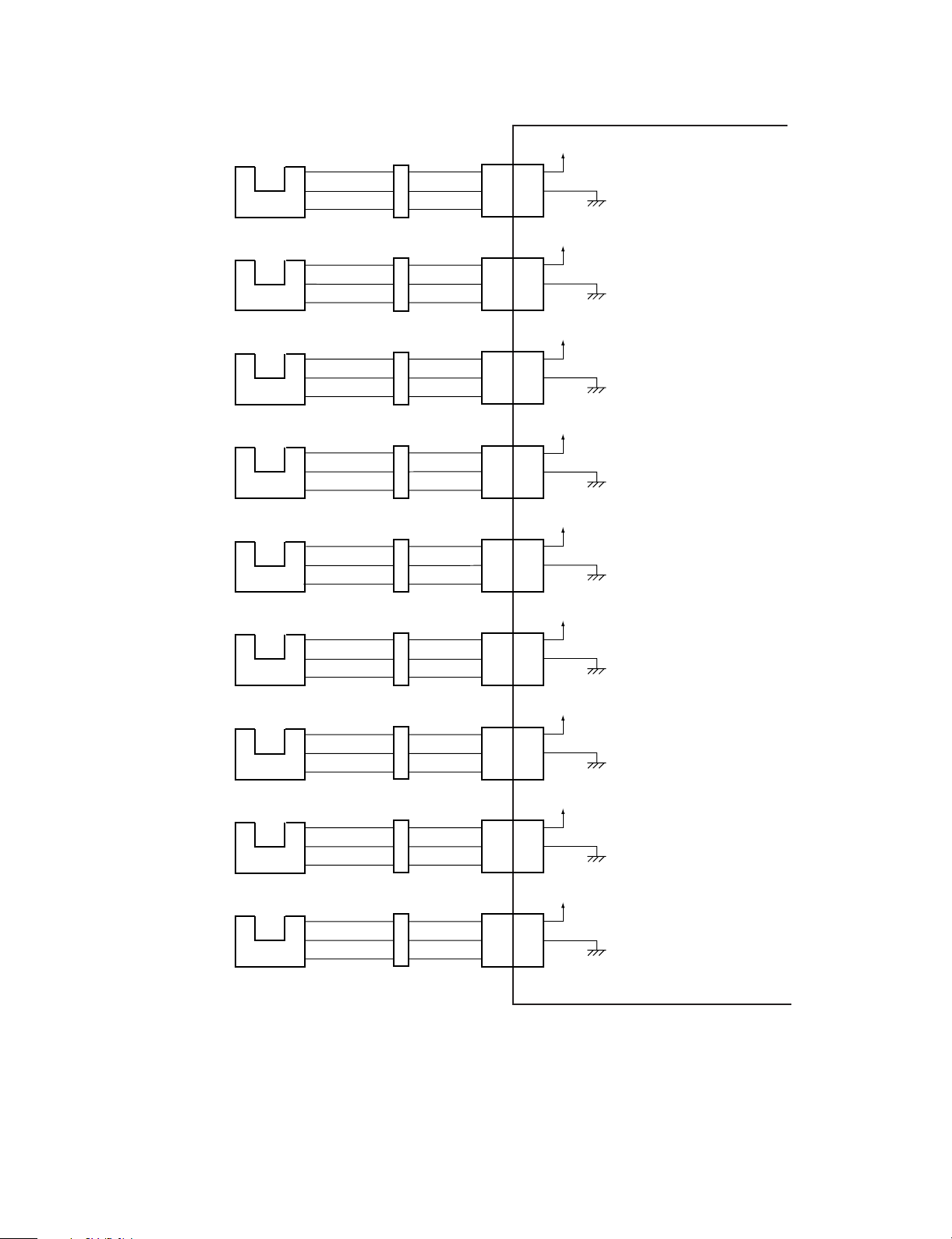
C. Finisher controller PWB input/output
• Finisher controller PWB input (1/2)
Paper exit motor
clock sensor
S1
J602
J601
1
2
3
Finisher controller PWB
J10
+5V
1
2
S1D
3
Pulse corresponding to the rotating
speed of the paper exit motor
Entry port sensor
Return roller
home position sensor
Joint sensor
Intermediate process
tray sensor
Front alignment plate
home position sensor
Rear alignment plate
home position sensor
Bundle exit lever
home position sensor
Stack tray
lift clock sensor
S2
S3
S4
S5
S6
S7
S8
S9
J612
J603
J610
J504
J502
J503
J505
J609
J604B
B10
B11
B12
J601
4
5
6
J604
A4
A5
A6
J501
7
8
9
J501
1
2
3
J501
4
5
6
J501
10
11
12
J604B
B4
B5
B6
J11
B10
B11
B12
J10
4
5
6
J11
A4
A5
A6
J9
7
8
9
J9
1
2
3
J9
4
5
6
J9
10
11
12
J11
B4
B5
B6
S2D
S3D
S4D
S5D
S6D
S7D
S8D
S9D
+5V
"1" when paper is passing over the sensor.
(The light shield plate is at S2.)
+5V
"1" when the return roller is at the home position.
(The light shield plate is at S3.)
+5V
"0" when the finisher is connected with the copier.
(The light shield plate is not at S4.)
+5V
"1" when paper is over the sensor.
(The light shield plate is at S5.)
+5V
"1" when the front alignment
plate is at the home position.
(The light shield plate is at S6.)
+5V
"1" when the rear alignment
plate is at the home position.
(The light shield plate is at S7.)
+5V
"0" when the bundle exit
lever is at the home position.
(The light shield plate is not at S8.)
+5V
Pulse corresponding to the rotating
speed of the stack tray lift motor
Fig. 3-103
3 – 2
Page 8

• Finisher controller PWB input (2/2)
Stack tray
height sensor
S10
J611
J604B
B7
B8
B9
Finisher controller PWB
J11
+5V
B7
B8
B9
S10D
"1" when the top surface of paper
is detected.
(The light shield plate is at S10.)
Stack tray
paper sensor
Stack tray
lower limit sensor
Stack tray
upper limit sensor
Stapler empty
sensor
Stapler cue sensor
Stapler stapling
home position
sensor
S11
S12
S13
S15
S16
S17
J702
J607
J608
8
13
9
11
12
J402
J701
J604A
A7
A8
A9
J604
A1
A2
A3
J401
13
11 11
12 12
J12
1
2
3
J11
A7
A8
A9
J11
A1
A2
A3
J8
8
13
9
S11D
S12D
S13D
S15D
S16D
S17D
+5V
"1" when paper is over the sensor.
(The light shield plate is at S11.)
+5V
"1" when the stack tray is at the
lower limit.
(The light shield plate is at S12.)
+5V
"1" when the stack tray is at the
upper limit.
(The light shield plate is at S13.)
"1" when stapler empty.
(The light shield plate is not at S15.)
"1" when the stapler head is not
at the stapling position.
"0" when the stapler is at
the stapling home position.
(The light shield plate is at S17.)
+5V
1
2
3
8
9
Stapler cartridge
sensor
Reverse roller
Home position
sensor
Reverse paper
exit sensor
Reverse entry port
sensor
(Reflection
transmiss type)
7
S18
Stapler unit
J1201
J1201
S19
S20
+5V
Reverse entry port sensor PWB
J204
1
1
2
2
3
3
Reverse driver PWB
J1501
4
3
2
1
J1401J301
4
3
2
1
+5V
J201 J1006
J1502
Fig. 3-104
J1009
J614
J1402
J1004
J616
J1001
B5 B5B4 B4
J613
7
7
S18D
J14
S190
J17
1
1
2
2
S20D
3
3
1
1
2
3
4
S21D
2
S21AN
3
4
"1" when the stapler cartridge is
not set.
"0" when the reverse roller is at
the D cut.
(When the shield plate is not at S19.)
+5V
"1" when paper is passing over the
sensor.
(When the shield plate is at S20.)
"0" when paper is passing over the
sensor.
+5V
3 – 3
Page 9

• Finisher controller PWB output
Paper exit
motor
Bundle
process
motor
Front
alignment
motor
Rear
alignment
motor
Stack
tray lift
motor
Staple
motor
M1
M2
M3
M4
M5
M6
Staple unit
J402
Finisher controller PWB
J4
1
M1DA
2
M1DB
3
M1DA*
4
M1DB*
5
6
J5
J201J202
1
1
M2DA
2
2
M2DB
3
3
M2DA*
4
4
M2DB*
5
5
6
6
J6
J301J302J304
1
1
M3DA
2
2
M3DB
3
3
M3DA*
4
4
M3DB*
5
5
6
6
J6
J301J303J305
7
7
M4DA
8
8
M4DB
9
9
M4DA*
10
10
M4DB*
11
11
12
12
J3
M5D1
1
2
M5D2
J8
J401
1
1
2
2
4
4
5
5
The rotating speed and the
rotating timing are controlled
by varying the sequence of
drive pulses (A, A*, B, B*)
and the frequency.
24V
The rotating speed and the
rotating timing are controlled
by varying the sequence of
drive pulses (A, A*, B, B*)
and the frequency.
24V
The rotating speed and the
rotating timing are controlled
by varying the sequence of
drive pulses (A, A*, B, B*)
and the frequency.
24V
The rotating speed and the
rotating timing are controlled
by varying the sequence of
drive pulses (A, A*, B, B*)
and the frequency.
24V
Forward rotation when M5D1
is "0" and M5D2 is "1"
Reverse rotation when M5D1
is "1" and M5D2 is "0"
Stop when M5D1 is "0" and
M5D2 is "1"
Forward rotation when M6DA
is "0" and M6DB is "1"
M6DA
Reverse rotation when M6DA
M6DB
is "1" and M6DB is "0"
Stop when M6DA is "0" and
M6DB is "1"
Reverse
paper exit
motor
Reverse
motor
Reverse
flapper
solenoid
M7
M8
SL1
J1103J1105
J1302J1303
M7DA
M7DB
M7DA∗
M7DB∗
M8DA
M8DB
M8DA∗
M8DB∗
SL1D
J203J1101
1
1
2
2
3
3
4
4
5
5
6
6
Reverse driver PWB
J203J1101
1
1
2
2
3
3
4
4
5
5
6
6
Reverse driver PWB
J1301
J205
1
212
IC201
Moter
driver
24V
IC202
Moter
driver
24V
24V
J201
Reverse driver PWB
Fig. 3-105
A6
A5
A4
A3
B1
B2
A8
A7
A1
A2
B3
J1006
A6
A5
A4
A3
B1
B2
J1006
A8
A7
A1
A2
J1006
B3
J1009
J1003J1008
J1004J1009
J1003J1008
J1004
J1001J1102J1104
J14
A3
A4
A5
A6
B8
B7
A1
A2
A8
A7
TRNSMA
A3
TRNSMB
A4
TRNSMA∗
A5
TRNSMB∗
A6
TRNSMC1
B8
TRNSMC2
B7
J14
BUFMA
A1
BUFMB
A2
BUFC1
A8
BUFC2
A7
By changing the sequence
and the frequency of drive
pulses (A, A∗, B, B∗), the
rotating speed and the
rotating timing are controlled.
By changing the sequence
and the frequency of drive
pulses (A, A∗, B, B∗), the
rotating speed and the
rotating timing are controlled.
J14
B6 B6
BUFSL
"1" when solenoid ON.
3 – 4
Page 10

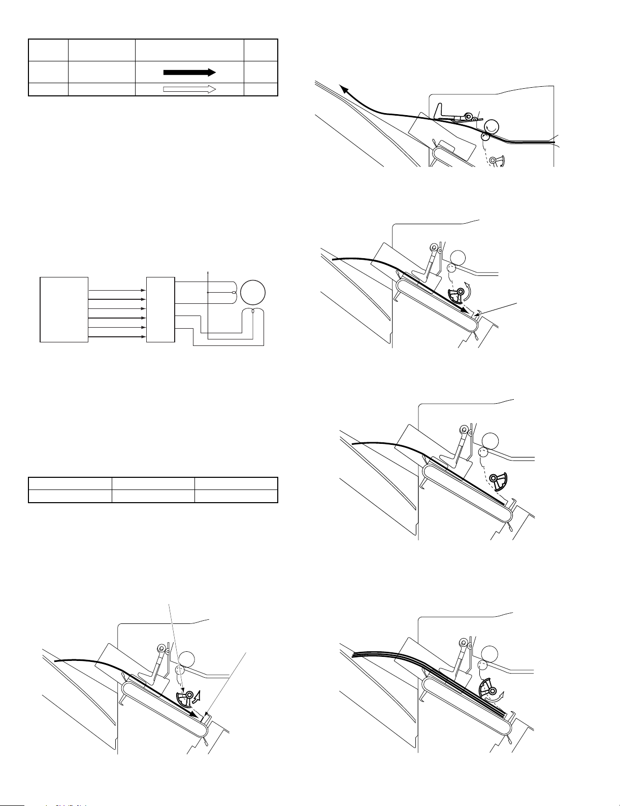
2. Basic operation
The basic operation is described below.
A. Face-up paper exit
In the face-up paper exit, the flapper solenoid turns on to switch the
paper path. Then paper passes through the following path.
B. Face-down paper exit
1) In the facedown paper exit, the flapper solenoid turns off to switch
the paper path, transporting paper to the reverse section.
3) Reverse rotation the semicircular roller furthermore to transport
paper to the paper exit roller side in the reverse section.
C. Face-up/face-down common operations
1) Paper is transported from the reverse section.
2) When the reverse entry port sensor detects the rear end of paper,
reverse rotation the semicircular roller to hold paper.
Fig. 3-201
2) Paper reaches the intermediate process tray.
Fig. 3-202
3) Paper is fed to make contact with the stopper plate by the return
roller.
3 – 5
Fig. 3-203
Page 11

4) Paper is aligned with the front/rear alignment plates.
Fig. 3-204
5) Operations of 1) through 4) are repeated for the specified pages of
paper, and the pages are loaded on the intermediate process tray.
6) Stapling is performed. (Specified stapling position)
Paper feed guide A
Return roller
Intermediate
process tray
loading guide plate
Bundle exit lever
Paper feed
guide B
S1
M1
J10-3
S1D
J4
Paper exit roller
J11-18
S2D
M2
One-way clutch
J9-9
S5D
J5
Finisher controller PWB
Fig. 3-301
B. Paper exit
Paper fed from the copier is transported to the intermediate process
tray by the paper exit motor (M1). Paper transport is detected by the
entry port sensor (S2).
Paper feed guides A/B are provided at the paper exit port of this
machine. Paper feed guides A/B lower the rear edge of paper by their
weight to support transporting discharged paper to the return roller.
Paper feed guide A
Paper feed guide B
Paper exit roller
Fig. 3-205
7) Paper bundle on the intermediate process tray is discharged to
the stack tray.
Fig. 3-206
3. Transport system
A. Outline
Paper is fed from the copier and discharged to the intermediate
process tray, where alignment and offset and stapling are made.
Then paper is discharged to the stack tray.
A jam in the machine is detected by the entry port sensor (S2).
The figure below shows the composition of the transport system.
Code Name
M1 Paper exit motor
M2 Bundle process motor
S1 Paper exit motor lock sensor
S2 Entry port sensor
S5 Intermediate process tray paper sensor
Tab. 3-301
S2
Fig. 3-302
4. Intermediate process tray section
A. Intermediate process tray operation
(1) Outline
The intermediate process tray makes a bundle of paper to align,
offset, and staple paper discharged from the copier.
The intermediate process tray section is composed of the return roller
and the bundle process belt. The bundle process belt is provided with
the bundle exit lever. The two bundle process levers are driven in
parallel.
When paper is stored in the intermediate process tray, the intermediate process tray paper sensor (S5) turns on.
When the power is supplied to the copier, the bundle process motor
(M2) is driven to return the return roller and the bundle process belts
to their home positions.
Bundle
process
motor
M2
One-way clutch
Return roller home position sensor (S3)
Return roller
Stack tray side
Bundle exit belts
Fig. 3-401
3 – 6
Page 12
Motor
rotation
Drive Arrow in Fig. 3-401
Forward Bundle exit belt
Drive
torque
High
Return roller
Reverse Return roller Low
Tab. 3-401
(2) Bundle process motor (M2) control
The bundle process motor (M2) is a 4-phase stepping motor.
Forward/reverse rotation of the motor and the rotating speed are
controlled by the phase of the pulse signals BUNDPINA,
BUNDPINA*, BUNDPINB and BUNDPINB* sent from the CPU to IC6.
IC6 outputs pulse signals A, A*, B, and B* corresponding to the shift
of BUNDPINA and BUNDPINB to control the motor rotating direction
and the rotating speed.
The motor torque is controlled by the combination of current control
signals BUNDCURA and BUNDCURB sent from the CPU to IC6.
In this machine, the motor is driven at a high torque when driving the
bundle exit belt (forward rotation), and at a low torque when driving
the return roller (reverse rotation).
Bundle
process
J5-1
motor
-5
-3
-2
-6
-4
M2
IC1
CPU
BUNDPINA
BUNDPINB
BUNDPINA*
BUNDPINB*
BUNDCURA
BUNDCURB
IC6
Motor
driver
A
A*
B
B*
Fig. 3-402
(3) Max. load capacity of the intermediate process tray
The max. load capacity of the intermediate process tray is shown in
the table below.
When the set number of pages or the number of documents exceeds
the max . load cap acity , the docu me nts of the max. lo ad capa cit y are
aligned and offset on the intermediate process tray. Then the bundle
of paper is discharged to the stack tray, and the remaining number of
paper is aligned.
When offsetting, all pages of a bundle are offset in the same direction.
Small size Middle size Large size
30 20 15
Tab. 3-402
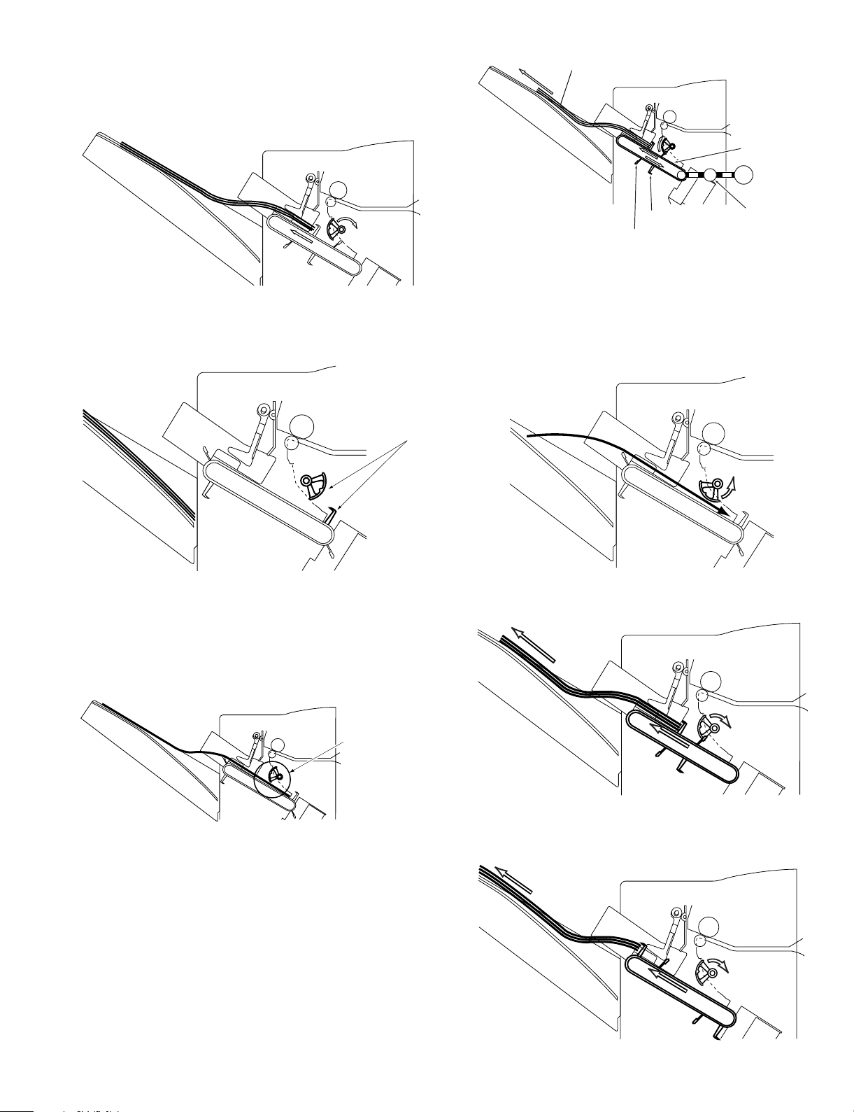
B. Return roller
(1) Outline
The return roller leads the discharged paper from the copier to the
stopper plate to align in the transport direction.
The return roller is driven in the forward direction when the bundle
process motor is reversed.
Return roller
(2) Operational descriptions
The operational descriptions of the return roller are given below.
1) Paper is discharged from the copier.
Fig. 3-405-a
2) The return roller rotates forwardly, and the paper reaches the
intermediate process tray and makes contact with the stopper
plate.
Stopper plate
Fig. 3-405-b
3) The roller rotates one turn and stands by at the home position. In
the case of the large/middle size or manual paper feed, the return
roller holds paper at the stand-by position.
Fig. 3-405-c
4) When the next paper is discharged from the copier, operations of
1) and 2) are repeated to form a bundle of paper.
When the last paper of a bundle is brought into contact with the
stopper plate, the return roller passes the home position and stops
at 1/8 turn.
Fig. 3-404
Stopper plate
Fig. 3-405-d
3 – 7
Page 13
5) After completion of alignment of the first set, the bundle is discharged by the bundle discharge lever. At the same time, the
return roller rotates in the reverse direction. Since, however, the
return roller has been off from the home position, it does not
interfere the bundle.
Bundle of paper
Bundle exit belt
M2
Fig. 3-405-e
6) The bundle process belt reaches the home position to complete
bundle exit. At the same time, the return roller stops at the home
position.
Home position
Fig. 3-405-f
7) When the next bundle is fed, operations of 1) to 6) are repeated.
• Paper holding in manual paper feed of large/middle size paper
In the case of manual paper feed, the max. load capacity of the
intermediate process tray is 5 pages. For manual paper feed of
large/middle size paper, paper tends to be folded. To prevent
against this, the return roller holds paper until the next paper is fed.
Bundle exit lever
Intermediate process tray
load support plate
One-way clutch
Fig. 3-409
(2) Operational descriptions
The operational descriptions of the bundle exit belt are given below.
1) Press the copy start key of the copier, and paper is stored in the
intermediate process tray. The return roller brings paper into contact with the stopper plate to align. The specified number of paper
is loaded in the intermediate process tray.
Fig. 3-410-a
2) The bundle exit belt is driven to transport the bundle of paper to
the stack tray.
The return roller
holds paper after
paper makes
contact with the
stopper plate.
Fig. 3-406
C. Bundle exit belt drive
(1) Outline of operation
The two bundle exit belts are driven in parallel when the bundle
process motor (M2) rotates forwardly.
The bundle exit belt is provided with two bundle exit belts on the
opposing positions. A bundle is discharged with a half turn of the
bundle exit belts.
When the power is supplied to the copier, the bundle process motor
(M2) is driven to set the bundle exit lever to the home position.
Fig. 3-410-b
3) Just before the bundle is discharged to the stack tray, the bundle
exit belt speed is reduced to prevent against misalignment due to
collision.
Fig. 3-410-c
3 – 8
Page 14

4) After discharging the bundle to the stack tray, it stops at the home
position.
Fig. 3-410-d
5) After the stack tray is lowered, the bundle exit belt and the return
roller move to the home position simultaneously, and wait for the
next paper.
Fig. 3-410-e
D. Alignment/offset
(1) Outline
Paper is aligned in the width direction by the front/rear alignment
plates on the intermediate process tray.
The front alignment plate is driven by the front alignment motor (M3),
and the rear alignment plate by the rear alignment motor (M4).
The front alignment plate home position sensor detects the front
alignment plate home position, and the rear alignment plate home
position sensor detects the home position of the rear alignment plate.
The tables below show the alignment positions.
Kind of sorting Alignment position
Non-sort Offset alignment (Front)
Staple sort Rear alignment
Sort Offset alignment
Tab. 3-403
Reference
When the operation is started, this machine is initialized. When, therefore, the power is supplied with the front/rear alignment plates being
off from the home position, they do not move to the home position.
Front side
Front alignment plate
Front alignment
plate home
position
sensor (S6)
Stack tray
Rear alignment plate
(2) Alignment motor control
Fig. 3-413 shows the drive circuit of the front alignment motor (M3)
and the rear alignment motor (M4).
Both motors are 4-phase stepping motors.
IC1 (CPU) delivers the following signals to control the motors. (Tab.
3-405)
Kind Signal name Target motor
Motor rotating direction,
Speed control
Motor drive enable FJOGPER
Drive current select FJOGCUR
IC1 controls the timing of JOGPINA and JOGPINB according to the
drive direction (forward, reverse) and the speed.
IC1 delivers FJOBPER or BJOGPER to IC14 depending on which
motor is driven, the front or the rear motor. When FJOGPER is outputted, IC14 sends JOGPINA and JOGPINB to IC7 (motor driver IC).
IC7 delivers 4-phase motor drive signals (FJOGA, FJOGB, FJOG_A,
and FJOB_B) according to JOGPINA and JOGPINB. In the same
manner, when BJOGPER is outputted, IC14 sends JOGPINA and
JOGPINB to IC8 (motor driver IC). IC8 delivers 4-phase motor drive
signals (BJOGA, BJOGB, BJOG_A and BJOB_B) according to JOGPINA and JOGPINB.
FJOGPER and BJOGPER are motor drive enable signals, and the
motor on the side where the signal is outputted is driven.
During halt of the motor, IC7 and IC8 continue to output the last
phase signal to hold the motor.
FJOGCUR and BJOGCUR outputted from IC1 are the motor current
select signals. (Tab. 3-406)
State Control current
Motor drive High current (High torque)
Motor hold Low current (Low torque)
Finisher controller PWB
IC1
(CPU)
JOGPINA
JOGPINB
FJOGPER
BJOGPER
FJOGCUR
BJOGCUR
JOGPINA
JOGPINB
BJOGPER
BJOGCUR
Tab. 3-405
Tab. 3-406
IC14
5V
5V
IC14
5V
5V
Front alignment motor,
Rear alignment motor
Front alignment motor,
Rear alignment motor
Front alignment motor,
Rear alignment motor
+24VP
FJOGA
FJOG_A
IC7
FJOGB
FJOG_B
+24VP
BJOGA
BJOG_A
IC8
BJOGB
BJOG_B
J6
1
5
3
2
6
4
J6
7
11
9
8
12
10
Front alignment
plate motor
Rear alignment
plate motor
M3
M4
Front alignment motor (M3)
Rear alignment motor (M4)
Rear alignment plate home position sensor (S7)
Fig. 3-412
Fig. 3-413
Rear side
3 – 9
Page 15

(3) Rear alignment (when staple sorting)
The stapler of this machine is fixed on the rear side. When stapling,
therefore, paper is aligned on the rear side.
When the copy start key is pressed and the paper size information is
sent from the copier, the rear alignment plate moves to the home
position, and the front alignment plate moves to the half of paper
width + 10mm forward from the center of the stack tray.
Paper discharged from the copier is transported to the intermediate
process tray.
When the paper is stored in the intermediate process tray, it is
brought into contact with the stopper plate by the return roller and
aligned in the transport direction. Then the paper is shifted to the
staple position. The front alignment plate is driven to align paper to
the rear side.
Rear alignment
plate home
position
To perform alignment backward, the rear alignment plate is driven
to the end of paper to be offset. To perform alignment forward, the
front alignment plate is driven to the end of paper to be offset.
When, however, the paper size is A4, A3, or A3W, the home
position of the front alignment plate serves as the reference of
forward offset, and the home position of the rear alignment plate
as the reference of backward offset. The active alignment plate
(the rear alignment plate for backward alignment, or the front
alignment plate for forward alignment) is in stand-by at the home
position.
When performing alignment, the alignment plate is moved from
the home position to the offset paper end. (Refer to Fig. 3-415-b.)
When the set number of paper or the number of documents exceeds the max. load capacity of the intermediate process tray, the
max. load capacity of paper is then discharged. Then the following
paper is aligned in the same direction.
Rear alignment
plate home
position
Half of
paper width
+ 10mm
Fig. 3-414-a
A3,A4
20mm
Stack tray
center
Front alignment
plate home
position
Rear alignment
plate home
position
Offset
quantity
20mm
Fig. 3-415-a
A3,A4
20mm
20mm
Front alignment
plate home
position
Rear alignment
plate home
position
Front alignment
plate home
position
Fig. 3-414-b
(4) Offset alignment (Non binding)
1) Sort
When sorting, paper bundles are offset and aligned. This is called
offset alignment.
The offset quantity of bundles is 20mm.
The offset direction of the first bundle is in the reverse direction of
the previous job. When the last section of the previous job is offset
backward (toward you), the first bundle is offset forward (to the
rear), and vice versa.
When the paper size information is issued from the copier, the
finisher controller PWB drives the front and the rear alignment
plates simultaneously to shift the paper by the paper width center
+ 10mm. (Refer to Fig. 3-415-a.)
When performing alignment, either of the front or the rear alignment plate is drive.
Front alignment
plate home
position
Fig. 3-415-b
3 – 10
Page 16

2) Non-sort
When non-sorting, paper is aligned at the backward offset position
(toward you) in sorting.
Rear alignment
plate home
position
20mm
3) Paper is stored in the intermediate process tray.
Front alignment
plate home
position
Fig. 3-416-a
Rear alignment
plate home
20mm
A3,A4
position
Front alignment
plate home
position
Fig. 3-416-b
(5) Operational descriptions
a. Staple sort
The staple sort operations are described below.
1) Press the copy start key of the copier.
The copier issues information on staples and the paper size.
2) The front alignment plate is moved to the position of half of paper
width + 10mm backward from the stack tray center.
Rear alignment
plate home
position
Fig. 3-417-b
4) The front alignment plate is driven to align paper.
5) The front alignment plate is returned to the position of 2).
Fig. 3-417-c
6) Operations of 3) to 5) are repeated every time when paper is
discharged from the copier.
7) When alignment of the first set is completed, stapling is performed.
8) The bundle process belt is driven to discharge the bundle to the
stack tray.
Half of
paper width
+ 10mm
Fig. 3-417-a
10mm
Stack tray
center
Front alignment
plate home
position
Fig. 3-417-d
9) The stack tray is moved to the specified height.
10) The operations of 3) to 8) are repeated.
Reference
When the number of documents exceeds the max. load capacity of
the intermediate process tray, stapling is not performed and the
bundle of paper on the intermediate process tray is discharged to the
stack tray. Stapling is not performed for the remaining set number of
paper, either.
3 – 11
Page 17

b. Offset alignment
The offset alignment operations are described below.
When non-sorting, paper is offset only backward (toward you) and
aligned.
1) Press the copy start key of the copier.
The copier issues information on staples and the paper size.
2) The front/rear alignment plates are moved to the position of half of
paper width + 10mm backward/forward from the center of paper
placed on the tray.
Rear alignment
plate home
position
10mm
10mm
6) The operations of 3) to 5) are repeated every time when paper is
discharged from the copier.
7) The bundle is discharged.
(a) When the number of documents is within the max. load
capacity of the intermediate process tray:
Each bundle is discharged to the stack tray.
(b) When the number of documents exceeds the max. load
capacity of the intermediate process tray:
The bundle on the intermediate process tray is discharged to
the stack tray.
The remaining number of documents is aligned at the same
offset position and the bundle is discharged to the stack tray.
Front alignment
plate home
position
Fig. 3-418-a
3) Paper is stored in the intermediate process.
Fig. 3-418-b
4) When aligning backward (toward you), the rear alignment plate is
driven to align paper. When aligning forward, the front alignment
plate is driven.
5) The front or the rear alignment plate comes to the position of 2).
Fig. 3-418-d
8) The stack tray is moved to the specified height.
9) The operations of 3) to 9) are repeated by alternating the alignment plates to be driven.
20mm
Fig. 3-418-e
5. Stapling operation
(1) Outline
The staple unit of this machine is fixed to the rear side, and not
shifted or oscillated.
Stapling is made at one position. Stapler is punched from the lower
side of a bundle before discharge.
This machine is not provided with a manual stapling function.
Stapling home position
Fig. 3-418-c
20mm
Stapling position
Fig. 3-501
3 – 12
Page 18

Reference
When the set number or the number of documents exceeds the staplable number of pages, stapling is not performed and the bundle is
discharged to the stack tray.
(2) Staple unit
The table below shows the motors and the sensors related to the
stapler.
Code Name SW/PI Role Remark
M6 Staple motor
S15 Stapler cue
sensor
Punches staples. Inside the
—
SW Detects if staples
are at the
staple unit
Inside the
staple unit
stapling position.
If not, punching is
made without
stapling to get a
staples ready to
stapling.
S16 Stapler empty
sensor
PI Detects the
remaining
Inside the
staple unit
quantity of
staples in a
cartridge.
S17 Stapler stapling
home position
sensor
S18 Stapler
cartridge sensor
PI Detects the home
position of
stapling.
SW Detects insertion
of a cartridge in
Inside the
staple unit
Inside the
staple unit
the stapler unit.
SW: Micro switch
PI: Photo interrupter
Tab. 3-502
When a finger is inserted into the stapling section, the stapler safety
sensor (S14) cuts off the power supply for safety.
CAUTION
When paper is loaded in the stack tray and the staple mode is
selected on the operation panel, the instruction to remove paper is
displayed and copying is allowed. If, however, copying is started
without removing paper from the stack tray, alignment and stapling
operations cannot be guaranteed.
(3) Staple motor control
Fig. 3-502 shows the drive circuit of the staple motor (M6).
The staple motor is a DC motor.
The motor rotating direction is controlled by the signal sent from the
finisher controller PWB IC4 (Communication IC) to the motor drive
circuit. (Refer to Tab. 3-503.)
24VP
6. Stack tray operations
(1) Stack tray lift operation
a. Outline
This machine is provided with one stack tray. A bundle of paper which
is aligned, offset, and stapled is discharged to the stack tray.
When paper is first discharged to the stack tray, the stack tray paper
sensor (S11) turns on.
The stack tray lift operation is performed by the stack tray lift motor
(M5).
When the power is supplied to the copier, if the stack tray is not at the
home position, the stack tray lift motor drives the stack tray to the
home position. The stack tray home position means the position
12.5mm above from detection of the stack tray top by the stack tray
paper height sensor.
The stack tray position is detected with the clock number of shifting
from the stack tray paper height sensor (S10).
The upper limit of the stack tray is detected by the stack tray upper
limit sensor (S13), the lower limit by the lower limit sensor (S12).
When the stack tray upper/lower limit sensor turns on, the stack tray
lift motor can be driven only in the opposite direction of the sensor
which is on.
The limit of load of the stack tray is detected by the paper height
sensor and the lower limit sensor in the case of non binding. When
stapling, the load count is also used in addition to them. When the
height or the limit of the specified number is detected, the notice of
load over is given to the copier.
Load limit detection
Non binding Paper height detection
Binding Paper height detection or load count
Tab. 3-601
Stack tray upper
limit sensor
Stack tray paper
height sensor flag 2
Stack tray paper
Stack tray
height sensor flag 1
Stack tray paper
height sensor
Paper hold lever
IC4
(COMMUNI-
CATION IC)
Finisher controller PWB
STPLCW
STPLCCW2
STPLCW2
STPLCCW
Q20
5V
Q26
IC9
5V
IC9
Q21
Q25
J8-1
-2
-4
-5
Fig. 3-502
Direction Output signal
Forward STPLCW/STPCW2
Reverse STPLCCW/STPCCW2
Tab. 3-503
Staple motor
M5
M6
Stack tray
lower limit
sensor
Fig. 3-601
b. Stack tray lift operation
When a bundle of paper is discharged to the stack tray, the stack tray
moves down until the stack tray paper height sensor (S10) turns off.
Then the stack tray moves up to 12.5mm above from detection of the
top of paper on the stack tray by the paper height sensor (S10).
3 – 13
Page 19

Stack tray
down
Stack tray
Fig. 3-602
Stack tray
up
Fig. 3-603
(2) Stack tray paper height detection
In any mode, the stack tray load quantity is detected with the height of
paper loaded on the stack tray.
The height of paper on the stack tray is detected by the stack tray
paper height sensor (S11).
When the paper is discharged, the stack tray moves down until the
stack tray paper height sensor (S10) does not detect, and it stops.
Then the paper height sensor (S10) moves up 12.5 mm past the point
where it detects the top of the paper in the stack tray.
When the stack tray lower limit sensor detects the stack tray with the
stack tray paper height sensor being detecting the paper top, the
finisher controller PWB gives the copier notice of over load. When the
loaded paper is removed from the stack tray, the stack tray moves up
to the home position. Then the paper can be discharged.
OFF
Stack tray paper
height sensor
Stack tray paper
height sensor flag
Fig. 3-605-a
ON
The flag is pressed
by the bundle of paper.
Fig. 3-605-b
(3) Stack tray load count
The table below shows the max. load of the stack tray.
When binding, the stack tray load limit is detected with the load count
on the stack tray in addition to the paper height detection. At that
time, a bundle of paper is counted by one. When the count reaches
30 in total, the notice of the stack tray load over is given to the copier.
The copier then gives a display of the instruction on the operation
panel to remove the bundle of paper.
When copying is made continuously, if paper is loaded on the stack
tray and staple sort is selected, the instruction to remove paper is
displayed on the operation panel and copying is allowed. If copying
made without removing paper at that time, alignment and stapling
operations cannot be guaranteed.
When the copy start key is pressed, though paper is not removed, the
count of paper bundles is cleared to zero.
Stack tray max. load capacity
Small size Max. 50 prints (Max. 20 sheets)
Middle size Max. 50 prints (Max. 20 sheets)
Large size Max. 50 prints (Max. 15 sheets)
Tab. 3-602
(4) Stack tray paper holding
The paper hold lever is provided beside the stack tray paper height
sensor.
The paper hold lever prevents against erroneous detection of the
paper height due to curling of a bundle.
The paper hold lever is driven by the stack tray lift motor (M5).
When a bundle of paper is discharged to the stack tray, the bundle is
loaded on the paper hold lever. After a bundle of paper is discharged
to the stack tray, the stack tray moves down until the stack tray paper
height sensor (S10) turns off, and it stops.
At that time, the paper hold lever is stored in the finisher away from
the bundle of paper.
Then the paper height sensor (S10) moves up 12.5 mm past the point
where it detects the top of the paper in the stack tray.
At that time, the paper hold lever appears from the finisher and presses the paper on the stack tray.
The above operations are repeated to hold paper.
3 – 14
Page 20

Semi-circular gear
M5
(Tray lifting up)
M5
(Tray moving down)
The semi-circular gear and
the paper hold lever are fixed
to the same axis.
Paper hold lever
Fig. 3-606
7. Jam detection
A. Outline
To detect paper empty and normal transport of paper, the following
sensors are provided.
• Entry port sensor (S2)
• Return roller home position sensor (S3)
• Bundle exit lever home position sensor (S8)
To detect normal stapling, the following sensor is provided.
• Staple home position sensor (S17)
Jam is checked by the check timing stored in the CPU on the finisher
controller PWB. When a jam is detected, the paper exit operation is
interrupted and a jam display is made on the operation panel.
Entry port
sensor (S2)
Return roller
home position
sensor (S3)
Bundle exit lever
homeposition
sensor (S8)
Fig. 3-607
(5) Tray lift motor control
a. Outline
Fig. 3-608 shows the block diagram of the tray lift motor (M5) drive
circuit.
The tray lift motor is a DC motor.
The rotating direction of the motor is controlled by the signal sent
from the finisher controller PWB IC1 (CPU) to the motor drive circuit.
(Refer to Tab. 3-603.)
When the stack tray reaches the stack tray upper limit sensor (S13)
and the sensor sends a signal (S13D) to IC11, STCTCW2 is interrupted and the motor stops its forward rotation.
Similarly, when the stack tray reaches the stack tray lower limit sensor (S12) and the sensor sends a signal (S12D) to IC11, STCTCCW2
is interrupted and the motor stops its reverse rotation.
Finisher controller PWB
IC1
(CPU)
STKTCW
STKTCCW2
S12D
IC11
S13D
S12
Stack tray
lower limit
sensor
S13
Upper limit
sensor
STKTCW2
STKTCCW
Fig. 3-608
Direction Output signal
Forward STKTCW/STKTCW2
Reverse STKTCCW/STKTCCW2
Tab. 3-603
Q25
Q27IC11
24VP
Q22
Q26
J3-1
Stack tray
lift motor
-2
M5
Fig. 3-701
8. Power system
(1) Outline
When the copier power is turned on, two voltages of 24V DC are
supplied from the copier to the finisher controller PWB. One is for
driving motors. The other is for generating 5V DC in the regulator IC
(IC12) of the finisher controller PWB. 5V DC is used as the power
source for sensors and IC’s on the PWB.
Fig. 3-801 shows the block diagram of the power supply system.
Finisher controller PWB
24V
Staple unit
drive circuit
5V
system
Logic
Copier
24V
Circuit
breaker
CB1
Regulator
IC (IC12)
Fig. 3-801
(2) Protection function
For protection against an overcurrent, the circuit breaker (CB1) is
provided for 24V DC for driving motors.
Motors
M
Staple motor
M6
Sensors
3 – 15
Page 21

[4] DISASSEMBLE AND ASSEMBLE
This Chapter describes the mechanical features, operations, and disassembly and assembly procedures.
When performing disassembly and assembly, observe the following
precautions.
1) Before disassembly and assembly, be sure to disconnect the
power plug.
2) For assembly procedures, reverse the disassembly procedures
unless otherwise specified.
3) Be careful of the kinds (length and diameter) of screws and fixing
positions.
4) For preventing static electricity, a inner-crip is provided at one
position of the metal cover. Be sure to use this shake proof
washer.
5) On principle, do not operate the machine with a part disassembled.
1. Reverse section
A. Reverse unit
Note: When removing the reverse unit, lift the unit and disengage the
hook.
C. Reverse roller/Reverse motor
2. Exterior control
A. Exterior covers
When performing cleaning, inspection, and repair of the machine,
remove the cover as required in the following procedure.
[3]
[1]
[4]
[1]
[2]
[1]
[5]
[4]
[3]
B. Reverse paper exit roller/reverse paper exit
motor
[2]
Fig. 4-101
4 – 1
[1]
Fig. 4-102
[2]
[3]
Page 22

B. Right inside cover and rear cover removal
To remove the right inside cover [1], remove the five fixing screws [2]
and remove the two fixing screws [4] of the rear cover [3].
[2]
[2]
[2]
[4]
[3]
3) Remove the two screws [4] and remove the discharge needle [5].
[5][4]
Fig. 4-106
D. Note for tightening the self tap screw
1) Fit the tip of a screw with a screw hole, and turn the screw
counterclockwise temporarily.
2) Check that the screw meets the screw hole thread.
3) Turn the screw clockwise to fix.
[1]
[2] [4]
Fig. 4-103
C. Discharge needle removal
1) Lift the upper guide plate [1] to the upper limit and fix it with tape.
Fix with tape.
[1]
Fig. 4-104
2) Pull up paper feed guide A [2] and paper feed guide B [3] and fix
with tape.
[3][2][3]
Fig. 4-107
E. Note for handling the load wall
Be careful not to scratch or damage the load wall rails [1]. If
damaged, they would adversely affect the load capacity.
[1]
[1]
Fig. 4-107a
Fig. 4-105
4 – 2
Page 23

F. Use of the stack tray stopper screw
The stack tray stopper screw [1] should be tightened in the plate to
the very end. (It should not be loosened.) If not, tight it may touch and
hook the rail slide.
3. Process tray
A. Process tray removal
1) Remove the right inside cover and the rear cover. (Refer to Fig.
4-103.)
2) Remove the stapler cover.
3) Remove the stapler. (Refer to Fig. 4-619.)
4) Remove the stack tray lift motor clock sensor holding plate. (Refer
to Fig. 4-610.)
5) Remove the fixing screw [1] and remove the entry port sensor [2].
[2] [1]
Fig. 4-301
6) Remove the E-ring [4] of the coupling shaft [3], and slide the gear
[5] and the bushing [6] toward you.
Note: When sliding the gear, be careful not to lose the parallel pin.
[1]
Fig. 4-108
2. Transport section
A. Transport motor removal
1) Remove the right inside cover and the rear cover. (Refer to Fig.
4-103.)
2) Disconnect the connector (J4) [2] on the finisher controller PWB
[1], remove two fixing screws [3], and remove the transport motor
[4].
[4]
[3]
[2]
[3]
[5]
[6]
[4]
Fig. 4-302
Fig. 4-201
[1]
4 – 3
Page 24

7) Remove the belt [8] from the pulley [7] on the rear frame side of
the coupling shaft [3], and pull out the coupling shaft [3].
[8]
[7] [3]
Fig. 4-303
8) Remove two connectors (J6, J9) [10] on the finisher controller
PWB [9], remove two fixing screws [11] inside the machine, and
remove two fixing screws [12] of the machine frame. (The grounding plate [13] will come off at that time.) Remove the process tray
unit [14] toward the machine.
[11] [11]
Note 1: When removing the fixing screw of the machine frame, the
stack tray may be in the way. Rotate the clock plate of the
stack tray shift motor clockwise as shown in Fig. 4-306a to
lower the stack tray, making an easy access to the fixing
screw.
Clock plate
Fig. 4-306a
Note 2: When attaching the process tray, check that the four load
wall rails [15] are securely engaged with the process tray unit
[14] as shown in Fig. 4-306b.
[14]
[14]
[14]
[9]
Fig. 4-304
[12]
[10]
[10]
[15]
Pawl
Fig. 4-306b
B. Alignment motor removal
1) Remove the process tray unit. (Refer to Fig. 4-301 – 306.)
2) Remove two fixing screws [1] and one connector [2], and remove
the alignment motor [3]. (There are two alignment motors. The
removal procedure is the same.)
[2]
[2]
[13]
Fig. 4-305
4 – 4
[1]
[3]
[1]
[1] [3] [1]
Fig. 4-307
Page 25

C. Alignment width adjustment
Note: When "B. Alignment plate angle adjustment" or "C. Sensor flag
overlap quantity adjustment" is performed, be sure to perform
this adjustment.
Refer to the following descriptions of "Adjustments."
D. Alignment plate angle adjustment
Refer to the following descriptions of "Adjustments."
E. Sensor flag overlap quantity adjustment
Refer to the following descriptions of "Adjustments."
4. Return roller
A. Return roller unit removal
1) Remove the process tray unit. (Refer to Fig. 4-301 – 306.)
2) Remove the fixing screw [1], and remove the return roller home
position sensor holding plate [2].
[2] [1]
B. Return roller rubber removal
1) Peel the return roller rubber [1] from the return roller [2].
[1] [2]
Fig. 4-405
C. Return roller rubber installation
1) Attach the return roller rubber [2] to the groove in the surface of
the return roller [1] from the bottom.
At that time, gradually turn the return roller [1] in the paper feed
direction.
[2]
1) 2) 3)
[1]
Fig. 4-401
3) Remove three fixing screws [4] of the lower guide [3], and remove
the return roller unit [5] together with the lower guide.
[3]
Fig. 4-402
[5]
[4]
[6]
[7]
[4]
[3]
[4]
4) Rotate the roller shaft [7] until the return roller [6] is not in contact
with the lower guide [3]. Pull out the return roller unit.
Fig. 4-406
Reference
To turn the return roller [1], turn the transport belt [3] back and forth
by inches. (Fig. 4-407a)
If the transport belt [3] is turned only backward, the transport belt arm
[4] may interfere with the belt home position sensor [5]. (Fig. 4-407b)
When turning the transport belt [3], do not hold the intermediate tray
load guide plate [6]. (Fig. 4-407c)
[3]
Fig. 4-407a
[3]
[4]
[1]
[5]
[3]
[6]
Fig. 4-403 Fig. 4-404
[7]
Fig. 4-407b
4 – 5
Page 26

[3]
[6]
Fig. 4-407c
D. Bundle process motor belt tension adjustment
Refer to the following descriptions of "Adjustments."
7) Remove the fixing screw [1] and remove the joint sensor holding
plate [2]. Remove the two fixing screws [3] and remove the paper
exit motor [4].
[1]
[2]
[3]
[4]
5. Stack tray
A. Stack tray removal
1) Remove the four fixing screws [1] at the back of the stack tray,
and remove the stack tray [2].
Note: When removing the stack tray, be careful not to damage the
wire which connects the stack tray and the finisher controller
PWB.
[1]
[2]
Fig. 4-501
[1]
6. Stack tray lift unit
A. Stack tray lift unit removal
1) Remove the right inside cover, the rear cover, and the stapler
cover. (Refer to Fig. 4-103.)
2) Remove the process tray unit. (Refer to Fig. 4-301 – 306.)
3) Remove the fixing screw [1] and remove the paper height sensor
unit [2] from the copier.
4) Remove the return roller unit. (Refer to Fig. 4-401 – 402.)
5) Remove the finisher controller PWB. (Refer to "8. PWB.")
6) Release the stack tray guide lever fixing plates backward and
forward. (Refer to "D. Stack tray guide lever fixing plate release.")
[3]
Fig. 4-602
8) Remove the fixing screw [8] of the front side plate, and remove the
lower limit sensor holding plate [9].
[9] [8]
Fig. 4-603
9) Remove the two fixing screws [10], and remove the handle unit
[11].
[10] [11] [10]
[1][2]
Fig. 4-601
Fig. 4-604
4 – 6
Page 27

10) Remove the fixing screw [12] and remove the grounding wire
[13].
11) Remove the six fixing screws [14] of the rear side plate.
[14]
14) Remove the five fixing screws [19] under the body frame [18],
and remove the stack tray lift unit together with the right inside
cover.
[19] [19]
[14]
[12]
[13]
[14]
Fig. 4-605
12) Remove the six fixing screws [15] of the front side plate.
[15]
[15]
[19]
[18]
[19]
Fig. 4-608
Note 1: Before installing the stack tray lift unit, check that the stack
tray guide levers (backward and forward) are on the tension
spring.
Tension spring
Stack tray guide lever (Forward)
Forward
Tension spring
[15]
Fig. 4-606
13) Attach the five fixing screws [16] to fix the right inside cover [17].
[16]
[17]
[16]
Fig. 4-607
Stack tray guide lever (backward)
Backward
Fig. 4-609a
Note 2: When installing the stack tray paper height sensor, check
that the coupling sections of sensor flags 1 and 2 are
engaged with each other.
Sensor flag 1
Sensor flag 2
Fig. 4-609b
4 – 7
Page 28

B. Stack tray drive unit removal
1) Remove the right inside cover and the rear cover. (Refer to Fig.
4-103.)
2) Remove the stapler cover.
3) Remove the fixing screw [1] and remove the stack tray lift motor
clock sensor holding plate [2].
2) Attach the stack tray guide lever fixing plate [3] to the stack tray
guide lever by using the holes in the front/rear side plates.
3) Tighten the fixing screw [2] of the belt pulley plate [1], and stretch
the stack tray guide bar belt [4].
[1]
[2]
[2]
Fig. 4-610
4) Remove the three fixing screws [3] and the connector [4], and
remove the stack tray drive unit [5].
[3]
[5] [3]
Fig. 4-611
[1]
[4]
C. Stack tray drive unit belt tension adjustment
Refer to the following descriptions of "Adjustments."
D. Stack tray guide lever fixing plate release
Refer to the following descriptions of "Adjustments."
E. Stack tray guide fixing plate installation
1) Loosen the fixing screw [2] of the belt pulley plate [1] which is in
the upper side of the front/rear side plates, and loosen the tension
of the stack tray guide lever belt [4].
[1]
[2]
[4]
Fig. 4-617
Note: Install the stack tray guide lever fixing plate so that the lower
edge of the stack tray guide lever fits with the mark on the
frame. By this setup, the stack tray guide lever phases (backward and forward) meet each other.
[3]
Fig. 4-616
Guide lever
Mark
Fig. 4-618a
4 – 8
Page 29

8. PWB
A. Finisher controller PWB
1) Remove the rear cover. (Refer to Fig. 4-103.)
2) Remove the connectors [1] and fixing screws [2], and remove the
finisher controller PWB [3].
[1]
[1]
[1]
[1]
[2]
[2]
[1]
Guide lever
Mark
Fig. 4-618b
7. Stapler
A. Stapler removal
1) Remove the right inside cover and the rear cover. (Refer to Fig.
4-103.)
2) Remove the connector (J8) [2] on the finisher controller PWB [1].
Remove the two fixing screws [3] and remove the stapler [4].
[3][4]
[3]
[1]
[2]
[2]
[1]
Fig. 4-801
[1]
[5] MAINTENANCE
1. Periodic replacement parts
2. Consumable parts replacement
standard
No. Part name Q’ty of use Life Remark
1 Stapler 1 200,000 times
2 Discharge needle 1 1 million times
3 Return roller rubber 2 1 million times
3. Periodic maintenance
[3]
Fig. 4-701
[1] [2]
No. Part name Item Time Remark
1 Return roller Clean-up 120,000 times
4 Consumable parts
No. Part name Product name Capacity Remark
1 Staple AR-SC1 3,000 pcs
4 – 9
Page 30

[6] ADJUSTMENT
A. Alignment width adjustment
Note: When "B. Alignment plate angle adjustment" or "C. Sensor flag
overlap quantity adjustment" is performed, be sure to perform
this adjustment.
1) Remove the right inside cover and the rear cover.
(Refer to Fig. 4-103.)
2) Set the front alignment plate to the home position.
2-1) Set SW1 on the finisher controller PWB as shown in Fig.6-101.
6) Loosen the screw [2] of the home position sensor plate [1].
[1][2]
O
F
F
Fig. 6-101
2-2) Press SW2 on the finisher controller PWB.
1
2
3
4
5
6
7
8
• The front alignment plate moves to the home position.
3) Set the rear alignment plate to the home position.
3-1) Set SW1 on the finisher controller PWB as shown in Fig.6-102.
O
F
F
1
2
3
4
5
6
7
8
Fig. 6-104
7) Adjust the position referring to the indication. Move the backward
alignment plate home position sensor (S6).
Example 1) If the width in procedure 2 is 319mm, the difference
from the standard (317mm) is +2mm. Therefore,
move the sensor [3] by 2mm in the direction of arrow
A in Fig. 6-105.
Example 2) If the width in procedure 2 is 316mm, the difference
from the standard (317mm) is -1mm. Therefore, move
the sensor [3] by 1mm in the direction of arrow B in
Fig. 6-105.
[3]
AB
Fig. 6-102
3-2) Press SW2 on the finisher controller PWB.
• The rear alignment plate moves to the home position.
Rear alignment plate home position
Fig. 6-103
4) Measure the alignment width. (Standard: 317mm)
5) Remove the process tray. (Refer to Fig. 4-108 – 113.)
Fig. 6-105
Reference
There is the mark of the standard alignment width (317mm) at the
back of the right inside cover. Fold a large sheet of paper to fit with
the mark and use it for measurement of the alignment width.
Right inside cover
317mm
Large sheet of paper
Fig. 6-106
6 – 1
[4]
Page 31

B. Alignment plate angle adjustment
1) Loosen the two fixing screws [2] of the rear alignment plate [1] with
the process tray unit installed.
[2] [1]
5) With the rear alignment plate adjusted in procedure 2) as the
reference, adjust the front alignment plate so that the clearance
between A4/LTR paper and the lead edge of the front alignment
plate is 0 – 0.5mm), and tighten the fixing screw which was
loosened in procedure 4).
Fig. 6-107
2) Set several sheets of A4/LTR paper on the process tray, and
adjust the rear alignment plate. (At that time, adjust the clearance
between A4/LTR paper and the lead edge of the rear alignment
plate to 0 – 0.5mm.)
Paper
Screw
Alignment
Front alignment plate
Finisher body
Fig. 6-110
Paper
C. Sensor flag overlap quantity adjustment
Normally when a mechanical part is replaced, it is fit with the old scale
shown in Fig. 4-312. If, however, the sensor flag overlap quantity is
varied for some reason, perform the following adjustment.
1) Remove the process tray unit. (Refer to Fig. 4-301 – 406.)
2) Loosen the fixing screw [2] of the alignment plate adjustment plate
[1] on the backward and the forward side. Move the alignment
plate [3] left and right.
[1]
[2]
Push on
Finisher body
0 − 0.5mm
Fig. 6-108
3) Remove the process tray unit. (Refer to Fig. 4-301 – 406.)
4) Loosen the fixing screw [4] of the adjustment plate of the front
alignment plate [3] at the back of the process tray unit.
[3] [4]
Rear alignment plate
[3]
Fig. 6-111
3) Adjust so that the overlap quantity of the flag section of the
front/rear alignment plate over the sensor is 1.5mm – 2.0mm.
Tighten the screw to fix.
Sensor Sensor flag
[2]
[1]
[3]
Fig. 6-109
1.5 − 2.0mm
Fig. 6-112
6 – 2
Page 32

D. Bundle process motor belt tension adjustment
1) Remove the right inside cover and the rear cover. (Refer to Fig.
4-103.)
2) Use 64g/m2 paper to make a sheet of about 10 x 20mm, and fold
the sheet into four.
50mm
10mm
Fig. 6-113
3) Turn the motor shaft [1] to squeeze the sheet of paper [4] between
the belt [2] and the tension roller [3].
[2]
[3]
5) With the sheet of paper squeezed, set the return roller shaft [7] to
the lower limit and tighten the screw [6] of the tension arm plate
[5].
[7][6] [5]
Fig. 6-116
6) Remove the sheet of paper from the belt and the tension arm.
7) Check that the return roller shaft [7] moves smoothly up and down.
[7]
[1]
[4]
Fig. 6-114
4) Loosen the screw [6] of the tension arm plate [5]. (The tension arm
plate is pulled by the tension spring.)
[6] [5]
Fig. 6-117
E. Stack tray drive unit belt tension adjustment
1) Remove the right inside cover.
2) Remove the stack tray lift motor clock sensor holding plate.(Refer
to Fig. 4-610.)
3) Remove the stack tray drive unit. (Refer to Fig. 4-611.)
4) Loosen the adjustment screw [2] of the tension arm [1]. (At that
time, the tension arm returns to the position where a tension is
applied to.)
[1] [2]
Fig. 6-115
6 – 3
[1]
[2]
Fig. 6-118
Page 33

5) Tighten the adjustment screw to fix the tension arm [1] at its return
position.
[1] [2]
[1]
[2]
Fig. 6-119
F. Stack tray guide lever fixing plate release
1) Remove the right inside cover and the rear cover.
(Refer to Fig. 4-103.)
2) Remove the stapler cover.
3) Remove the stack tray. (Refer to Fig. 4-501.)
4) Turn the clock plate of the tray shift motor, and set the stack tray
guide lever fixing plate [1] so that it can be seen from the holes
(backward and forward) in the side plate. (Clockwise: down,
counterclockwise: up). Remove the fixing screw [2] and disengage
the hook of the fixing plate from the stack tray guide lever [3].
(Same procedures for backward and forward)
[1][2] [3]
Fig. 6-120
Note: When removing the fixing screw, press the stack tray guide
lever.
Stack tray lever
Fig. 6-121
6 – 4
Page 34

[7] TROUBLESHOOTING
A. Trouble code
Code Content Details
F1-00 • Copier connection trouble (Disconnection, broken cable) Communication between the copier and the finisher is interrupted,
• Finisher controller PWB or copier trouble
F1-02 • Paper exit clock sensor trouble, connector disconnection, or
broken cable
• Paper exit motor trouble or control PWB abnormality
• Paper exit motor load abnormality
• Reverse motor abnormality or connector disconnection, or
broken cable
• Finisher controller PWB or reverse driver PWB abnormality
• Reverse roller home position sensor abnormality, connector
disconnection, or broken cable
• Reverse roller load abnormality
F1-10 • Staple unit abnormality • In the staple operation, the staple unit once moves away from
• Staple home position sensor abnormality
• Staple binding cable abnormality
• Finisher controller PWB abnormality
F1-11 • Bundle process motor or control PWB abnormality • When the return roller is operated in the initial operation, it
• Return roller home position abnormality, connector
disconnection, or broken cable
• Bundle process motor interface binding cable abnormality
• Bundle push members abnormality
• Return roller abnormality
• Bundle motor or control PWB abnormality • When the bundle push member is operated in the initial
• Bundle push member home position sensor abnormality,
connector disconnection, or broken cable
• Bundle process motor interface binding cable abnormality
• Bundle push member abnormality
• Return roller abnormality
F1-15 • Stack tray motor or control PWB abnormality • When the stack tray is operated, the stack tray upper limit
• Stack tray home position sensor abnormality, connector
disconnection, or broken cable
• Stack tray shift clock sensor abnormality, connector
disconnection, or broken cable
• Stack tray motor load abnormality • When the stack tray is lifted, it does not reach the home
F1-19 • Front alignment motor or control PWB abnormality When the front alignment guide is operated in the initial operation,
• Front alignment home position sensor abnormality, connector
disconnection, or broken cable
• Front alignment motor binding cable abnormality
• Front alignment guide member load abnormality
F1-20 • Rear alignment motor or control PWB abnormality When the rear alignment guide is operated in the initial operation,
• Rear alignment home position sensor abnormality, connector
disconnection, or broken cable
• Rear alignment motor binding cable abnormality
• Rear alignment guide member load abnormality
and is not revived.
• In the initial operation, the edge of the paper exit clock sensor
signal is not detected.
• When the reverse roller is operated in the initial operation, it
does not move from the home position or it does not reach the
home position.
the staple home position, but does not reach the staple home
position again; though the staple operation is performed again,
it still does not reach the staple home position.
• In the staple operation, the staple unit does not move away
from the staple home position.
does not reach the home position.
operation, it does not move away from the home position or it
does not reach the home position.
sensor becomes active.
• When the stack tray is operated, the stack tray encoder clock
signal is not detected for 15 times or more.
position sensor.
• When the stack tray is moved down, it does not move away
from the home position.
it does not reach the home position or it does not move away from
the home position.
it does not reach the home position or it does not move away from
the home position.
7 – 1
Page 35

B. Self diag mode
This machine is provided with the self diag function to check the machine troubles, which are displayed with LED1 of the finisher control PWB.
1. Display method
The display method of LED1 is as shown below.
• LED display under the normal condition of the finisher
Blank Condition code display
One cycle
ON
OFF
300msec
150msec 150msec
• LED display under an abnormal condition of the finisher
One cycle
Header section Group Detail 1 Detail 2
ON
OFF
2000msec 1000msec
Interval
Group, Common, Detail 1, Detail 2
300msec 200msec 500msec
Header section: ON period - 2000msec, OFF period 100msec
Group Detail 1 Detail 2: ON period - 300msec, OFF period 200msec, Interval 500msec
The blinking cycle differs depending on the condition.
2. Display list
The display conditions are as shown in the table below.
LED1 display
Group Detail 1 Detail 2
11∗ Trouble display F1-10 Staple motor abnormality
12∗ Trouble display F1-15 Tray lift abnormality
13∗ Trouble display F1-19 Front alignment motor abnormality
14∗ Trouble display F1-20 Rear alignment motor abnormality
15∗ Trouble display F1-02 Paper exit motor abnormality
16∗ Trouble display F1-11 Bundle exit motor abnormality
17∗ Trouble display F1-11 Bundle exit motor abnormality
18∗ Trouble display F1-02 Paper exit motor abnormality
21∗ Jam display FRENT Reverse delay jam
22∗ Jam display FREXT Reverse remaining jam
23∗ Jam display FINPD Transport remaining jam
24∗ Jam display FINPD Transport remaining jam
25∗ Trouble display F1-10 Staple motor abnormality
26∗ Jam display FINPD Transport remaining jam
27∗ Jam display FINPD Transport remaining jam
28∗ Jam display FDOP (No jam history because of door open)
29∗ Jam display FINPD Transport remaining jam
3 1 1 Message display Stack tray over 50 continuous staple bundle exit
3 1 2 Message display Tray HP sensor and lower limit sensor ON
4 1 1 Message display Staple empty No detection of cartridge
4 1 2 Message display No detection of staple
4 2 1 Message display Staple overload 31 sheets or more of small size paper loaded.
4 2 2 Message display 21 sheets or more of middle size paper loaded.
4 2 3 Message display 18 sheets or more of large size paper loaded.
5 1 1 Message display Door open
* Refer to the procedures described below.
Condition Display on the copier side Content
7 – 2
Page 36

(1) Copier display "F1-00": Communication trouble between the machine and the finisher
Cause/Trouble position Procedure Check Result Remedy
Finisher controller PWB/
Copier main PCU PWB
Wiring 2 Check if connection between the finisher
Finisher controller PWB/
Copier main PCU PWB
1 Turn on/off the power switch, and check
if the trouble is canceled.
controller PWB and the copier main
PCU PW B i s n o rm a l .
3 Replace the finisher controller PWB and
the copier ma in PC U PW B , and check
if the trouble is canceled.
Yes End
No Repair the wiring.
Yes End
(2) Copier display "F1-02": LED display code [1 – 8 – ∗] (Paper exit motor (M1) trouble)
Cause/Trouble position Procedure Check Result Remedy
Paper exit roller 1 Manually turn the paper exit roller, and
check if it rotates smoothly.
Wiring 2 Check if wiring between the finisher
Paper exit motor clock sensor
(S1)
Paper exit motor (M1) 4 Replace the paper exit motor (M1) and
Finisher controller PWB No Replace the finisher controller PWB.
3 Check if the paper exit motor clock
controller PWB and the paper exit motor
(M1) is normal.
sensor (S1) is normal.
check if the trouble is canceled.
No Repair the mechanism.
No Repair the wiring.
No Replace the sensor.
Yes Replace the motor.
(3) Copier display "F1-11": LED display code [1 – 6 – ∗] (Bundle process motor (M2) trouble: Bundle exit (forward rotation)
direction)
Cause/Trouble position Procedure Check Result Remedy
Bundle process motor (M2) 1 Check if the drive belt tension is proper. No Loosen the screw to adjust the tension.
2 Check if the return roller bearing slides
up and down.
3 Check if the return roller spring is
disengaged.
Wiring 4 Check if the wiring between the finisher
controller PWB and the bundle process
motor (M2) is normal.
Bundle exit lever home
position sensor (S8)
Bundle process motor (M2) 6 Replace the bundle process motor (M2),
Finisher controller PWB No Replace the finisher controller PWB.
5 Check if the bundle exit lever home
position sensor (S8) is normal.
and check if the trouble is canceled.
No Apply grease to the sliding section.
Yes Repair the return roller spring.
No Repair the wiring.
No Replace the sensor.
Yes End
(4) Copier display "F1-20": LED display code [1 – 4 – ∗] (Rear alignment motor (M5) trouble)
Cause/Trouble position Procedure Check Result Remedy
Rear alignment home position
sensor (S7)
Wiring 2 Check if the wiring between the finisher
Rear alignment plate 3 Check if the rack is over the collar of the
Rear alignment motor (M4) 4 Replace the rear alignment motor (M4)
Finisher controller PWB No Replace the finisher controller PWB.
1 Check if the rear alignment plate home
position sensor (S7) is normal.
controller PWB and the rear alignment
motor (M4) is normal.
roller.
and check if the trouble is canceled.
No Replace the sensor.
No Repair the wiring.
Yes Repair.
Yes End
(5) Copier display "F1-10": LED display code [1 – 1 – ∗] (Staple motor (M6) trouble)
Cause/Trouble position Procedure Check Result Remedy
Wiring 1 Check if the wiring between the staple
unit and the finisher controller PWB is
normal.
Staple unit 2 Replace the staple unit and check if the
Finisher controller PWB No Repair the finisher controller PWB.
trouble is canceled.
No Repair the wiring.
Yes End
7 – 3
Page 37

(6) Copier display "F1-19": LED display code [1 – 3 – ∗] (Front alignment motor (M5) trouble)
Cause/Trouble position Procedure Check Result Remedy
Front alignment plate home
position sensor (S6)
Wiring 2 Check if the wiring between the finisher
Front alignment plate 3 Check if the rack is over the collar of the
Front alignment motor (M3) 4 Replace the front alignment motor (M3)
Finisher controller PWB No Replace the finisher controller PWB.
1 Check if the front alignment plate home
position sensor (S6) is normal.
controller PWB and the front alignment
motor is normal.
roller.
and check if the trouble is canceled.
No Replace the sensor.
No Repair the wiring.
Yes Repair.
Yes End
(7) Copier display "F1-11": LED display code [1 – 7 – ∗] (Bundle process motor (M2) trouble: return (reverse) direction)
Cause/Trouble position Procedure Check Result Remedy
Bundle process motor (M2) 1 Check if the return roller bearing slides
2 Check if the return roller spring is
3 Check if the bundle process motor drive
Return roller home position
sensor (S3)
Bundle process motor (M2) 5 Replace the bundle process motor (M2)
Finisher controller PWB No Replace the finisher controller PWB.
4 Check if the return roller home position
smoothly up and down for the slide
section in the front side plate.
engaged securely.
belt tension is proper.
sensor (S3) is normal.
and check if the trouble is canceled.
No Apply grease to the slide section.
No Repair the return roller spring.
No Loosen the tension adjustment screw
and retighten it.
No Replace the sensor.
Yes End
(8) Copier display "F1-15": LED display code [1 – 2 – ∗] (Stack tray lift motor (M5) trouble)
Cause/Trouble position Procedure Check Result Remedy
Stack tray lift motor (M5) 1 Manually turn the flag of the stack tray
Wiring 2 Check if the wiring between the finisher
Tray phase 3 Check if the phases in front of and at the
Stack tray lift motor clock
sensor (S9)
Stack tray paper height sensor
(S10)
Stack tray upper limit sensor
(S13), stack tray lower limit
sensor (S12)
Finisher controller PWB 7 Check if the voltage at J3-1 and -2 of
Stack tray lift motor (M5) Yes Check the wiring between the stack tray
4 Check if the stack tray lift motor close
5 Check if the stack tray paper height
6 Check if the stack tray upper limit sensor
lift motor clock sensor (S9), and check if
it rotates smoothly.
controller PWB and the stack tray lift
motor (M5) is normal.
rear of the stack tray are proper.
sensor (S9) is normal.
sensor (S10) is normal.
(S13) and the stack tray lower limit
sensor (S12) are normal.
the finisher controller PWB is 24V at the
rotating timing of the stack tray lift motor
(M5).
No Repair the mechanism
No Repair the wiring.
No Adjust so that they are proper.
No Replace the sensor.
No Replace the sensor.
No Replace the sensor.
No Replace the finisher controller PWB.
lift motor (M5) and the finisher controller
PWB. If it is normal, replace the motor.
(9) Copier display "F1-02": LED display code [1 – 5 – ∗] (Reverse motor (M8) trouble)
Cause/Trouble position Procedure Check Result Remedy
Reverse motor 1 Manually turn the reverse motor, and
check if it rotates smoothly.
Wiring 2 Check if the wiring between the finisher
Reverse roller home position
sensor
Reverse motor 4 Replace the reverse motor, and check if
Finisher controller PWB No Replace the finisher controller PWB.
3 Check if the reverse roller home position
controller PWB and the reverse motor is
normal.
sensor is normal.
the trouble is canceled.
No Repair the mechanism.
No Repair the wiring.
No Replace the sensor.
Yes Replace the motor.
7 – 4
Page 38

[8] SELF TEST MODE
1. DIP switch functions
The operations of DIP switches on the finisher controller PWB are described below.
• Operating procedure
1) Remove obstacles from the operating range of the target to be operated.
2) Set the DIP switch (SW1), and supply the power. (LED1blinks.)
3) Press the push switch (SW2), and the following operations are performed. (LED2 turns ON during operation.)
Setup Target to be operated Operation Other procedure of stopping
Paper exit motor The paper exit roller rotates by specified turns and stops. • Turn off the joint sensor
8ON7654321
Bundle process motor
(Bundle exit lever)
8ON7654321
Bundle process motor
(Return roller)
8ON7654321
Front alignment motor Not in the home position The front alignment plate
8ON7654321
Rear alignment motor Not in the home position The front alignment plate
8ON7654321
Stack tray motor (Up) The stack tray moves up,
8ON7654321
Stack tray motor (Down) The stack tray moves
8ON7654321
Staple motor After stapling, it stops. • Turn off the joint sensor
The bundle exit lever moves to the home position and
stops there.
The return roller moves to the home position and stops
there.
moves to the home position
and stops there.
In the home position It moves by the specified
distance in the pushing
direction and stops in the
home position.
moves to the home position
and stops there.
In the home position It moves by the specified
distance in the pushing
direction and stops in the
home position.
and detects the stack tray
upper limit sensor, and
stops.
down, and detects the stack
tray lower limit sensor, and
stops.
(S4).
• Turn off the joint sensor
(S4).
• Turn off the joint sensor
(S4).
• Turn off the joint sensor
(S4).
• Turn off the joint sensor
(S4).
• Turn off the joint sensor
(S4).
• Turn off the joint sensor
(S4).
• Turn off the joint sensor
(S4).
• Turn off the joint sensor
(S4).
(S4).
8ON7654321
Reverse paper exit motor The reverse paper exit roller rotates the specified number
of turns, and then stops.
8ON7654321
Reverse motor Reverse operation of one page • Turns off the joint sensor
8ON7654321
Flapper solenoid Turns on the solenoid and operate the flapper. • Turns off the joint sensor
• Turns off the joint sensor
(S4).
(S4).
(S4).
• Press SW2 again.
8ON7654321
Compulsory shift of offset
tray position
8ON7654321
The offset tray is shifted to the packing position.
Tab. 8-101
8 – 1
Page 39

[9] ELECTRICAL SECTION
A. Electrical parts arrangement
M1
S13
S11
S1
S3
M2
S12
S2
S10
M5
S6
M3
Fig. 9-201
(1) Sensors
Name Code Operation
Photo
interrupters
S1 Paper exit motor lock detection
S2 Paper entry port paper detection
S3 Return roller home position detection
S4 Finisher joint detection
S5 Intermediate process tray paper detection
S6 Front alignment plate home position detection
S7 Rear alignment plate home position detection
S8 Bundle push lever home position detection
S9 Stack tray lift motor clock detection
S10 Stack tray paper height detection
S11 Stack tray paper detection
S12 Stack tray lower limit detection
S13 Stack tray upper limit detection
Stapler quantity detection (inside the staple
S16
unit)
Stapler stapling home position detection
S17
(inside the staple unit)
S19 Reverse roller home position sensor
S20 Reverse paper exit sensor
Tab. 9-201
S4
S15-18
M6
[1]
S9
SL1
S7
M4
S5
M8
S8
(2) Motors
Name Code Operation
Motors M1 Paper exit motor
M2 Bundle process motor
M3 Front alignment motor
M4 Rear alignment motor
M5 Stack tray lift motor
M6 Staple motor
M7 Reverse paper exit motor
M8 Reverse motor
Tab. 9-202
(3) Micro switches
S19
M7
Name Code Operation
Micro
switches
S15 Stapler empty detection (inside the staple unit)
Stapler cartridge empty detection (inside the
S18
staple unit)
Tab. 9-203
(4) PWB
Code Name
[1] Finisher controller PWB
[2] Reverse driver PWB
[3] Reverse entry port sensor PWB
Tab. 9-204
(5) Solenoid
Code Name
SL1 Reverse flapper solenoid
Tab. 9-205
B. Finisher controller PWB LED’s and check pins
list
Among the LED’s and check pins of the machine, only those which
are necessary for servicing in the market are listed below.
Note:
1. Some LED’s flow leak current in the normal state and slightly
illuminate after turning off. Note that they are normal.
2. The check pins which are not listed below are provided for factory
adjustments. To adjust these pins, a special tool or a measurement
tool is required. A high level of accuracy in adjustments is also
required. Therefore, do not touch them in the market.
113
J6
J5
131 61 12
J15
J4
J3
12
J13
13 16
CB1
JP2
JP1 L2
J2
J1
2171 61B1B8
Fig. 9-202
SW1: For test mode setting
SW2: For test mode starting
LED1: For test mode (For error display)
LED2: For test mode
LED3: For test mode
J8
SW2 SW1
J12
2
1
LED1
LED2
LED3
J9
OFF
AB A1
J14
12
11
J10
61B1 B124131
J11
A12 A1
J16
J17
9 – 1
Page 40

[To Copier]
[10] ACTUAL WIRING CHART
Finisher Controller PWB
[REVERSE UNIT]
REVERSE ENTS
REVERSE DRIVER
10 – 1
Page 41

CAUTION FOR BATTERY REPLACEMENT
(Danish)
Lithiumbatteri – Eksplosionsfare ved fejlagtig håndtering.
Udskiftning må kun ske med batteri
Levér det brugte batteri tilbage til leverandoren.
(English)
Danger of explosion if battery is incorrectly replaced.
Replace only with the same or equivalent type
recommended by the manufacturer.
CONTAINS (MANGANESE DIOXIDE) LITHIUM PRIMARY
BATTERY MUST BE DISPORSED OF PROPERLY.
REMOVE THE BATTERY FROM THE PRODUCT AND
CONTACT FEDERAL OR STATE ENVIRONMENTAL
AGENCIES FOR INFORMATION ON RECYCLING
(Finnish)
Paristo voi räjähtää, jos se on virheellisesti asennettu.
Vaihda paristo ainoastaan laitevalmistajan suosittelemaan
tyyppiin. Hävitä käytetty paristo valmistajan ohjeiden
(French)
Il y a danger d’explosion s’ il y a remplacement incorrect
de la batterie. Remplacer uniquement avec une batterie du
même type ou d’un type équivalent recommandé par
Mettre au rebut les batteries usagées conformément aux
(Swedish)
Explosionsfara vid felaktigt batteribyte.
Använd samma batterityp eller en ekvivalent
typ som rekommenderas av apparattillverkaren.
Kassera använt batteri enligt fabrikantens
(German)
Explosionsgefahr bei Verwendung inkorrekter Batterien.
Als Ersatzbatterien dürfen nur Batterien vom gleichen Typ oder
vom Hersteller empfohlene Batterien verwendet werden.
Entsorgung der gebrauchten Batterien nur nach den vom
Hersteller angegebenen Anweisungen.
ADVARSEL !
af samme fabrikat og type.
Caution !
“BATTERY DISPOSAL”
AND DISPORSAL OPTIONS.
VAROITUS
mukaisesti.
ATTENTION
le constructeur.
instructions du fabricant.
VARNING
instruktion.
Achtung
Page 42

All rights reserved.
Printed in Japan.
No part of this publication may be reproduced,
stored in a retrieval system, or transmitted,
in any form or by any means,
electronic; mechanical; photocopying; recording or otherwise
without prior written permission of the publisher.
Trademark Acknowledgments
Microsoft Windows, MS-DOS, and Windows NT are trademarks of Microsoft Corporation in the
U.S.A. and other countries.
Macintosh, Power Macintosh, Mac OS, LaserWriter, and AppleTalk are registered trademarks of
Apple Computer, Inc.
IBM, PC/AT, and PowerPC are trademarks of International Business Machines Corporation.
Pentium is a registered trademark of Intel Corporation.
PCL is a trademark of the Hewlett-Packard Company.
PostScript® is a registered trademark of Adobe Systems Incorporated.
NetWare is a registered trademark of Novell, Inc.
All other trademarks and copyrights are the property of their respective owners.
SHARP CORPORATION
Digital Document Systems Group
Quality & Reliability Control Center
Yamatokoriyama, Nara 639-1186, Japan
2000 June Printed in Japan
 Loading...