

Page 1
AR-FN3
CODE: 00ZARFN3//A1E
3-TRAY FINISHER
MODEL AR-FN3
CONTENTS
[ 1 ] BASIC SPECIFICATIONS . . . . . . . . . . . . . . . . . . . . . . . . . . . . . 1-1
[ 2 ] UNPACKING AND INSTALLATION . . . . . . . . . . . . . . . . . . . . . 2-1
[ 3 ] EXTERNAL VIEW AND INTERNAL STRUCTURE . . . . . . . . . . 3-1
[ 4 ] OPERATIONAL DESCRIPTIONS . . . . . . . . . . . . . . . . . . . . . . . 4-1
[ 5 ] DISASSEMBLY AND ASSEMBLY . . . . . . . . . . . . . . . . . . . . . . 5-1
[ 6 ] ADJUSTMENTS . . . . . . . . . . . . . . . . . . . . . . . . . . . . . . . . . . . . 6-1
[ 7 ] MAINTENANCE . . . . . . . . . . . . . . . . . . . . . . . . . . . . . . . . . . . . . 7-1
[ 8 ] TROUBLESHOOTING . . . . . . . . . . . . . . . . . . . . . . . . . . . . . . . . 8-1
[ 9 ] CIRCUIT DESCRIPTIONS . . . . . . . . . . . . . . . . . . . . . . . . . . . . 9-1
[10] ELECTRICAL SECTION . . . . . . . . . . . . . . . . . . . . . . . . . . . . . 10-1
PARTS GUIDE
This document has been published to be used
for after sales service only.
The contents are subject to change without notice.
Page 2
AR-FN3
[1] BASIC SPECIFICATIONS
1. Ty pe
Copier-fitted type (detachable)
2. Tray
1) Number of trays 3
2) Type Top (tray 1) Normal tray
Middle (tray 2) Normal tray
Bottom (tray 3) Lift tray
3) Number of
sheets loadable
3. Paper transport
Center reference
4. St orag e
Face-down
5. Disch ar ge size
Face-down Top A3 ∼ A6R/11 × 17 ∼ 8.5 × 5.5,
Normal tray 500 (80 g/m2)
Lift tray 1500 (A4/11" × 8.5") 750
(A3/11" × 17") (80 g/m2)
special paper
Middle A3 ∼ A5/11 × 17 ∼ 8.5 × 5.5
Bottom A3 ∼ B5/ 11 × 17 ∼ 8.5 × 11
9. Staple unit
Paper discharge tray Lift tray
Storage Face-down
Number of sheets
that can be stapled
Paper size AB series A3, B4, A4, A4R, B5
Stapling reference 1 point (front)/ 1 point (far end)/ 2 points
Needle feed system Cartridge (5000 needles)
Detection No needle/no cartridge/stapler rotation
Service life more than 100 K
Manual mode None
50 sheets (80 g/m2)
25 sheets when the size is over A4/LT.
Inch series 11" × 17"/8.5" × 14"/
8.5" × 13"/8.5" × 11"/
8.5" × 11"R
10. P ower supply
Supplied from copier (DC 24V, DC 5V)
11. Power consumption
MAX 72W
12. Dimensions
590 (W) × 560 (D) × 998 (H)
13. Weight
About 50 kg
6. Paper weight
Face-down Top 50 ∼ 128 g/m2, 176g/m2, 200m
Middle 64 ∼ 128 g/m
Bottom 64 ∼ 128 g/m
2
2
7. Paper full detection
Top Provided
Middle Provided
Bottom Provided
8. Lift tray
Off-set 30 mm
2
8/6/1999 1 – 1
Page 3
AR-FN3
[2] UNPACKING AND
INSTALLATION
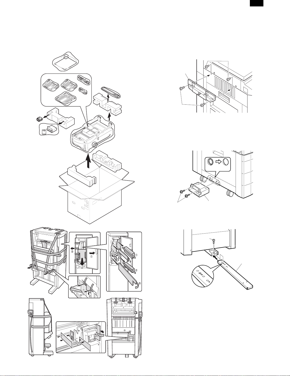
1. Unpac king
Refer to the sketch below for unpacking.
2. Installation
Unplug the copier’s power cord before carrying out
the following procedure.
1. Attach the lock plate and mounting plate.
Remove the two screws from the upper left cabinet of the copiery and
attach the lock plate to the upper left cabinet using two screws D.
Screws for upper
left cabinet
Lock plate
Screws D
2. Attach the mounting plate.
Cut out the two mounting holes (the leftmost hole and the third hole
from the left) at the lower part of the desk using a Phillips screwdriver,
etc., and remove the burrs using a flat-blade screwdriver, etc.
Then, attach the mounting plate to the lower part of the desk using
two screws A.
Mounting hole
Screws A
Mounting plate
3. Attach the connecting plate to the finisher.
Insert the connecting plate into the lower part of the finisher and
attach the plate at the position with mark B using screw B.
Screw B
Connecting plate
2 – 1 9/2/1999
Page 4
AR-FN3
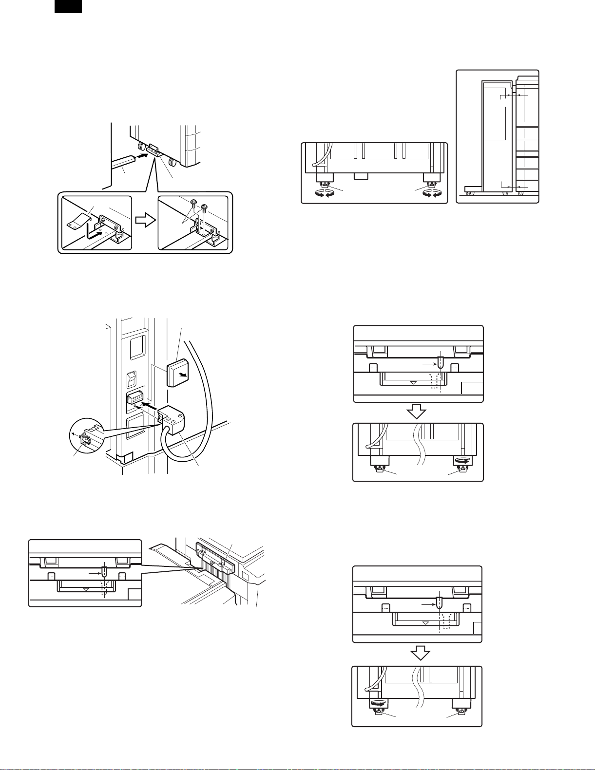
4. Insert the connecting plate of the finisher into the
mounting plate of the desk.
Insert the connecting plate which has been attached to the finisher
into the mounting plate of the desk.
Move the finisher away from the copier after insertion to check that
the connecting plate is locked.
While the plate is locked, attach the securing plate using two black
screws C.
Connecting
plate
Securing plate
Mounting plate
Screws C
5. Connect the finisher connector.
Cut the connector cover on the copier with nippers. Fit the finisher
relay harness to the copier and secure the connector by tightening
the connector screw.
Connector cover
• If the clearance is wide at the upper part:
Turn knob A and knob B counterclockwise so that the
clearances at the upper part and lower part are uniform.
Clearance
Clearance
Knob BKnob A
<2> If the guide pin of the lock plate does not match the connecting
hole of the finisher:
Turn the knobs at the lower part of the finisher to adjust the
height.
• If the connecting hole is offset toward the rear side:
Turn knob B counterclockwise so that the connecting hole
matches the guide pin.
Then, push the finisher into the copier.
If the clearance between the finisher and copier is not proper,
adjust the clearances at the upper part and lower part using
procedure <1>.
(Top view)
Screw
Connector
6. Check and adjust the height of the finisher.
• Put the finisher close to the copier and adjust and check so that
the guide pin of the lock plate enters smoothly the connecting hole
of the finisher.
(Top view)
Guide pin
Lock plate
• Since adjustment has been made at shipping, this adjustment is
basically not needed.
If the guide pin should not be inserted smoothly, adjust the height
using the following procedure.
<1> If the guide pin of the lock plate matches the connecting hole of
the finisher:
• If the clearance is narrow at the upper part:
Turn knob A and knob B clockwise so that the clearances at
the upper part and lower part are uniform.
Guide pin
Knob A
Knob B
• If the connecting hole is offset toward the front side:
Turn knob A counterclockwise so that the connecting hole
matches the guide pin.
Then, push the finisher into the copier.
If the clearance between the finisher and copier is not proper,
adjust the clearances at the upper part and lower part using
procedure <1>.
(Top view)
Guide pin
Knob A
Knob B
8/19/1999 2 – 2
Page 5

AR-FN3
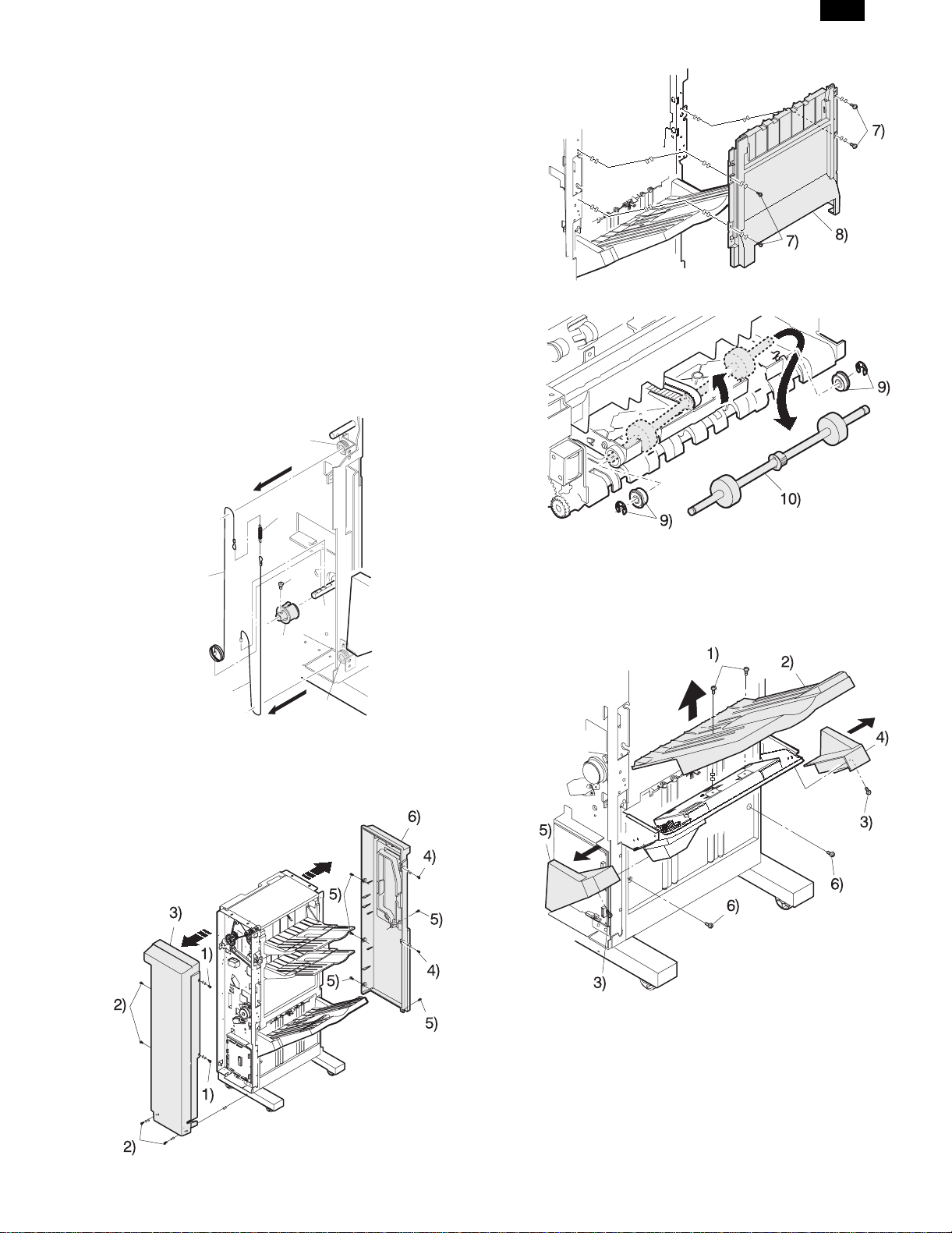
7. Attach the exit tray and tray 3.
Insert the three pawls at the rear side of tray 3 into the holes of the
tray mounting platform and secure the tray using two screws.
Attach the two exit trays to the finisher from the boss at <1>.
2
1
Exit trays
Screws D
Pawl
Pawl
Tray 3
Pawl
8. Attach the paper holder plates.
Attach the 2 paper holder plates to the attaching portion of the finisher
by fitting them as shown in the illustration.
Paper holder plates
4) Push the staple unit until it locks.
10. Paste the stapling position labels.
Stapling position label B
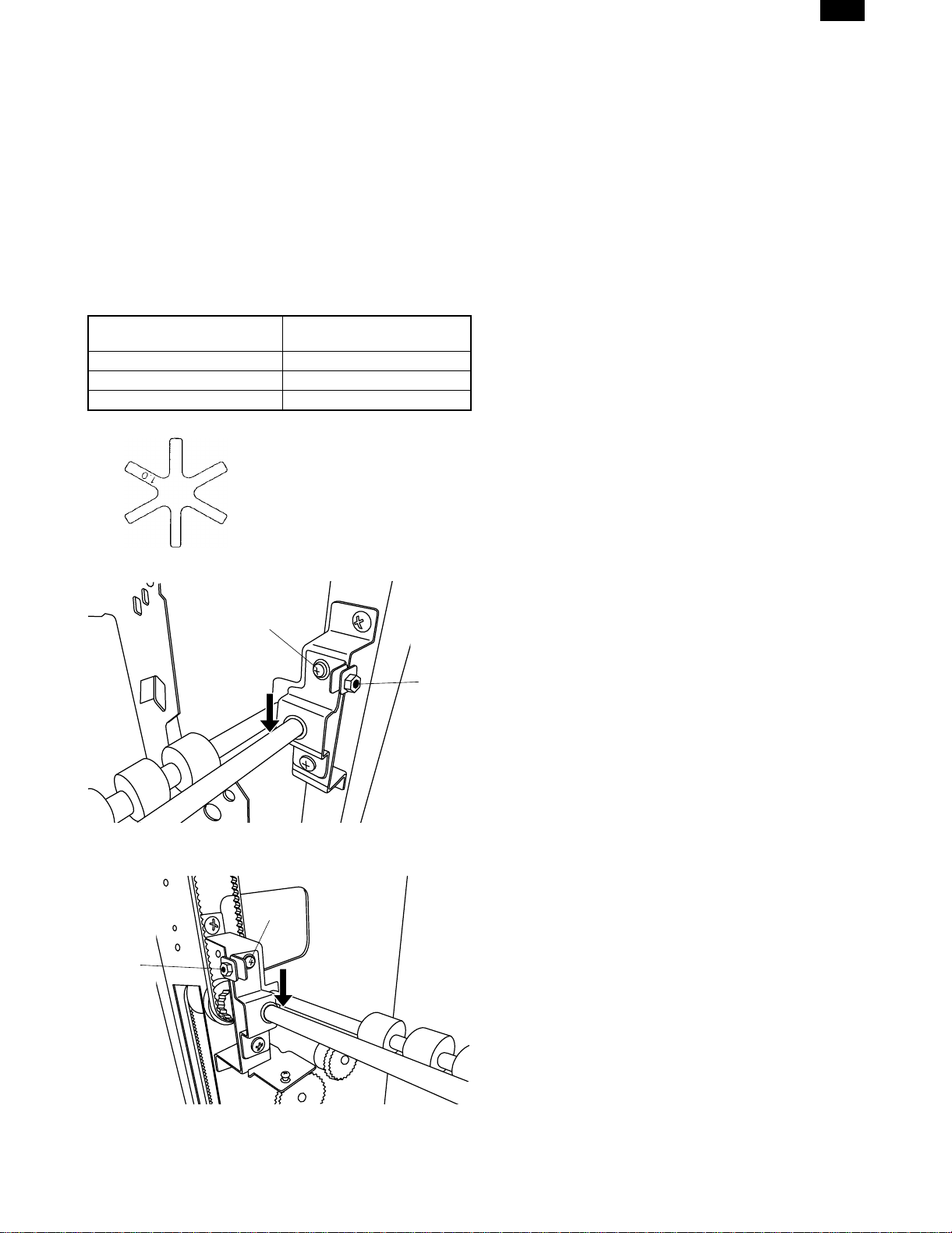
11. Remove the transport springs.
1. Pull out the exit unit of the copier until it stops.
2. Remove the 2 exit area cover securing screws and remove the
exit area cover.
3. Remove the 2 transport springs which are attached to the exit
area paper guide.
4. Store the 2 removed transport springs by hanging them on the exit
unit front frame (shown in Fig. 1).
5. Attach the exit area cover to its original position and secure it
using the 2 securing screws.
At this time, ensure that the pawls of the exit area cover are under
the paper guides. (See Fig. 2.)
Securing screw
Securing screw
Exit area cover
9. Attach the staple cartridge to the staple unit.
1) Insert the staple cartridge into the staple unit in the direction
shown in the illustration.
2) Push the staple cartridge in until it clicks in place.
3) Push down the lock release lever to unlock the staple unit.
Exit unit
Transport spring
Paper guides
[Fig. 2]
[Fig. 1]
Connect the power cord, turn the main switch ON,
and perform the following procedure.
12. Check the finisher operation.
• Check the operation in the STAPLE SORT mode.
Make 10 sheets of copies in the STAPLE SORT mode.
Check to see if the copies are stapled properly.
2 – 3 8/19/1999
Page 6

AR-FN3
[3] EXTERNAL VIEW AND
INTERNAL STRUCTURE
1. External view
1
3
4
5
2. Internal structure
15
4
14
13
10
12
11
4
18
16
17
4
10
9
2
10 1 2
3
4
19
4
5
6
7
No. Part name
1 Upper door
2 Front door
3 Tray 1
4 Tray 2
5 Tray 3
8
No. Part name
1 Paper discharge gate 1
2 Transport follower roller 2
3 Vertical transport roller 1
4 Transport follower roller 1
5 S tray reverse roller 50
6 Paper discharge pressure release roller
7 Paper discharge gate 3 F50
8 Paper discharge roller 4
9 Paper discharge roller 3
10 Follower roller FN3
11 Vertical transport roller 3
12 Paper discharge roller 2
13 Paper discharge gate 2
14 Paper transport roller 2
15 Paper discharge roller 1
16 De-curler roller 50
17 Vertical transport 3 lower
18 De-curler vertical follower shaft
19 Paper entry roller F50
8/6/1999 3 – 1
Page 7

3. Clutch, solenoid
AR-FN3
7
4
2
1
5
8
9
6
3
No. Signal code Name Function and operation
1 OG1SL Paper discharge gate solenoid 1 Switching tray 1 paper discharge gate
2 OG2SL Paper discharge gate solenoid 2 Switching tray 2 paper discharge gate
3 OG3SL Paper discharge gate solenoid 3 Switching tray 3 paper discharge gate
4 PPSL Paper holding solenoid Holding paper in staple tray
5 STSL ST paper holding solenoid Holding paper in staple tray
6 T3PDSL Tray 3 paper discharge paddler solenoid For tray 3 paper discharge paddler
7 T12CL Tray 1 and 2 speed reduction clutch Reducing speed of tray 1, 2 paper discharge roller
8 PDCL Paddler clutch For paddler in staple tray
9 STORCL ST paper discharge roller pressure release clutch Pressing staple tray paper discharge roller
3 – 2 8/6/1999
Page 8

AR-FN3
4. Sensor
2
1
23
27
25
10
6
11
17
7
21
15
16
13
24
26
Stapler unit
5
4
3
18
22
9
20
8
12
19
14
No. Signal code Name Function and operation
1 DSW1 Copier connection switch Detecting the finisher attached to the copier
2 DSW2 Top door opening switch Detecting top door opening
3 DSW3 Front door opening switch Detecting front door opening
4 INPD Paper entry sensor Detecting paper entry
5 PFD2 Transport sensor 2 Detecting paper transport 2
6 PFD3 Transport sensor 3 Detecting paper transport 3
7 PFD4 Transport sensor 4 Detecting paper transport 4
8 STID Staple paper entry sensor Detecting staple tray paper entry
9 STPD Staple tray paper sensor Detecting paper empty in staple tray
10 T1PF Tray 1 full sensor Detecting tray 1 full
11 T2PF Tray 2 full sensor Detecting tray 2 full
12 T3OD Tray 3 paper discharge sensor Detecting paper discharge in tray 3
13 T3UP Tray 3 upper limit sensor Detecting tray 3 upper limit
14 T3DN Tray 3 lower limit sensor Detecting tray 3 lower limit
15 EVRE Elevator motor encoder Elevator motor encoder
16 OFHP Offset motor home position sensor Detecting offset motor home position
17 JGHP Jogger motor home position sensor Detecting jogger motor home position
18 PSHP Pusher motor home position sensor Detecting pusher motor home position
19 STUHP Staple unit moving motor home position sensor Detecting staple unit moving motor home position
20 STORHP ST paper discharge roller pressure release clutch
home position sensor
21 T3PDHP Tray 3 paper discharge roller paddler home
Detecting ST paper discharge roller pressure release clutch home
position
Detecting tray 3 paper discharge roller paddler home position
position sensor
22 STID2 Staple tray paper entry sensor 2 Detecting staple tray 2 paper entry
23 STND Stapler replacement sensor Detecting rotation of stapler for replacement of stapler
24 STHP Stapler home position sensor Detecting stapler home position
25 LSTS Stapler sensor Detecting staple in stapler unit
26 NCTS Stapler cartridge sensor Detection cartridge in staple unit
27 READY Stapler self priming sensor Detecting that stapler is at the position ready for stapling
8/6/1999 3 – 3
Page 9

5. Motor and PWB unit
AR-FN3
1
3
4
7
2
6
5
9
10
11
No. Signal code Name Function and operation Type
1 FM Main drive motor Transports paper in the finisher. DC brushless
2 T3OM Tray 3 paper discharge drive motor Transports paper to tray 3. DC stepping
3 JGM Jogger motor Sets the jogger position for each paper size to align paper in
the staple tray.
4 PSM Pusher motor Lowers paper in the staple tray to the stapling position and lifts
to the paper discharge position.
5 STUM Staple unit moving motor Moves the staple unit to the stapling position. DC stepping
6 EVM Elevator motor Lifts and lowers tray 3 up and down. DC brushless
7 OFM Offset motor Shifts tray 3 front and back to sort paper in tray 3. DC brushless
8 STM Staple motor Drives the staple unit. DC brushless
9 — Finisher main PWB 100/200V Finisher control —
10 — Filter PWB Brush motor noise reduction —
11 — Filter PWB Brush motor noise reduction —
DC stepping
DC stepping
8
3 – 4 8/6/1999
Page 10
AR-FN3
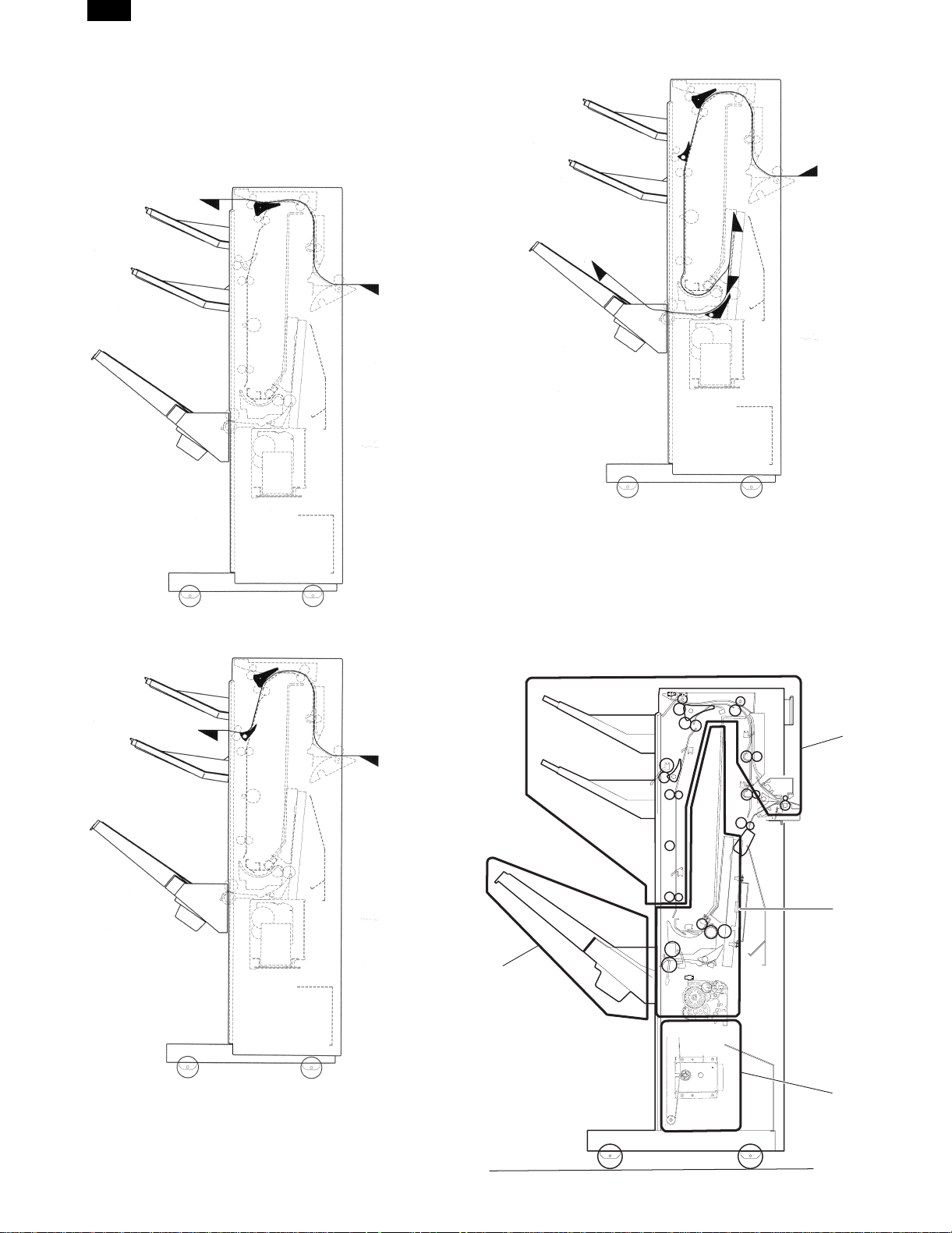
[4] OPERATIONAL DESCRIPTIONS
1. Transport route
The 3-tray finisher’s transport routes are as follows.
a) Tray 1 face-down paper discharge
c) Tray 3 outside turn face-down paper discharge
b) Tray 2 face-down paper discharge
2. Explanation of each section
The 3-tray finisher consists of (1) an upper paper transport section,
(2) a reversion section, (3) a staple tray, (4) an offset tray, and (5) an
elevator section.
It has the following functions: Paper discharge to a selected tray,
paper reversion, stapling for paper delivered to the offset tray (3
positions), offset, and elevation. Each function is performed according
to the mode instructed by the copier.
1)
3)
4)
8/19/1999 4 – 1
5)
Page 11

AR-FN3
A. Upper paper transport section
1) Paper transport
By rotating the main driving motor (FM), the transport rollers in the
finisher are driven.
2) Paper discharge gate 1 (1)
The paper discharge gate 1 (1) is operated by the paper discharge
gate 1 solenoid (OG1SL), to select between the routes for paper
discharge to the tray 1 (8) and transport to the tray 2 (5)/staple tray.
3) Paper discharge gate 2 (6)
The paper discharge gate 2 (6) is operated by the paper discharge
gate 2 solenoid (OG2SL) to select between the routes for paper
discharge to the tray 2 (5) and transport to the staple tray.
4) Trays 1 (8) and 2 (5) paper discharge operation
When paper is discharged to tray 1 (8) and tray 2 (5), tray 12 reduction clutch (11) is operated at the paper discharging timing to reduce
the speed of paper discharge rollers 1 and 2, improving the accuracy
of paper alignment in tray 1 (8) and tray 2 (5).
5) Trays 1 (10) and 2 (7) paper full detection
Whether the trays 1 (10) and 2 (7) are filled with paper is detected by
the tray 1 and 2 paper full sensor.
(9)
(8)
(5)
(7)
(6)
(10)
(11)
(1)
(2)
(3)
B. Staple tray
1) Jogger motor (JGM)
The jogger motor is driven when the paper is fed into the staple tray,
to operate the jog plates F and R so as to align the sideways edge of
the paper.
2) Paddler (11)
The paddler clutch (PDCL) is turned ON when the paper is fed into
the staple tray, to give the paddler a full turn so as to drop the paper
downward (pusher), thus achieving alignment in the vertical direction.
3) Pusher motor (PSM)
With the pusher motor rotating, the paper stored inside the staple tray
is lowered from the home position (discharge position) to the stapling
position; after stapling, the paper inside the staple tray is elevated
from the stapling position to the home position.
4) Staple unit movement motor (STUM)
The staple unit is moved to the stapling positions (front, far end, 2
centers) by the staple unit motor.
5) Staple tray paper discharge
When the paper delivery roller pressure release clutch (STORCL) is
turned ON, the paper delivery pressure release roller (4) is pressurized through the cam to discharge the paper from the stable tray.
6) Paper discharge gate 3 (5)
The paper discharge gate 3 (5) is operated by the paper discharge
gate 3 solenoid (OG3SL) to switch over the routes of paper inside the
staple tray between the paper discharge side and the staple side of
the off-set tray.
7) Tray 3 paper discharge motor
The tray paper discharge motor (12) is rotated to drive the paper
discharge rollers 3 and 4 to discharge paper to the tray 3.
(4)
(To staple tray)
No. Signal name Name
(1) — Paper discharge gate 1
(2) PFD2 Transport sensor 2
(3) INPD Paper entry sensor
(4) PFD4 Transport sensor 4
(5) — Tray 2
(6) — Paper discharge gate 2
(7) T2PF Tray 2 paper full detecting sensor
(8) — Tray 1
(9) PFD3 Transport sensor 3
(10) T1PF Tray paper full sensor
(11) T12CL Trays 1 and 2 deceleration clutch
(1)
(2)
(11)
(10)
(9)
(8)
(12)
No. Signal name Part name
(1) — Short path switching gate
(2) — Paper discharge roller 3
(3) — Pusher
(4) — Paper delivery pressure release roller
(5) — Paper discharge gate 3
(6) STPD Staple tray paper detection sensor
(7) — Staple unit
(8) T3ORSL Paper discharge roller 4
(9) T3OD Tray 3 paper discharge sensor
(10) STID Staple tray paper entry sensor
(11) — Paddler
(12) T3OH Tray 3 paper discharge motor
(4)
(5)
(6)
(7)
4 – 2 8/19/1999
Page 12

AR-FN3
(Operation of stapling)
1) 2) 2) 1)
Jog plate
R
Pusher
Paper size
Jog plate
F
Jogging in lateral direction
1) The jog plates are moved to the stand-by position before the
paper is fed to the staple tray.
2) Immediately after the paper is fed into the staple tray, the jog plate
is moved to the paper size position to ensure the alignment of the
paper.
Stapler unit movement at the time of stapling
(2-point stapling action is added.)
1) The pusher is elevated to the position which makes it possible for
the staple unit to move.
2) The staple unit is moved to the staple position where the 2nd
staple is driven.
3) The pusher (sheets to be stapled) is lowered to the stapling position.
4) Sheets are stapled.
5) The staple unit is returned to the 1st staple position.
(After the job is finished, the staple unit is returned to the home
position.)
D. Off-set tray
1) Off-set motor (3)
When the off-set motor (3) is driven, the tray is shifted sideways
against the direction in which the sheets are delivered, so that the
sheets discharged into the off-set tray (1) are sorted by the specified
number of sheets. The rotation is unidirectional and controlled by the
crank. The motor is stopped by the off-set home position sensor (2)
turning ON.
(3)
Staple unit
Home
position
Staple unit moving
motor
Pusher
2) 4)
3)
1)
5)
Paper discharge
position
Staple position
ST rail
Staple unit movement at the time of stapling (1-point
stapling)
1) The stapler unit is moved to the stapling position.
– The number of sheets to be stapled is fed to the staple tray –
2) The pusher (the sheets to be stapled) is lowered to the stapling
position.
3) The paper is stapled ... (in the case of 2-point stapling, the action
that is described on the following page is added.)
4) The pusher (the sheets stapled) is elevated to the paper discharge
position.
5) After the job, the stapler unit is returned to the home position.
Pusher
Staple unit
1)
3)
4)
5)
2)
moving range
Staple position
ST rail
(2)
(1)
Moving range
(30 mm)
No. Signal name Part name
(1) — Tray 3 (Off-set tray)
(2) OFHP OFHP Off-set home position sensor
(3) OFM Off-set motor
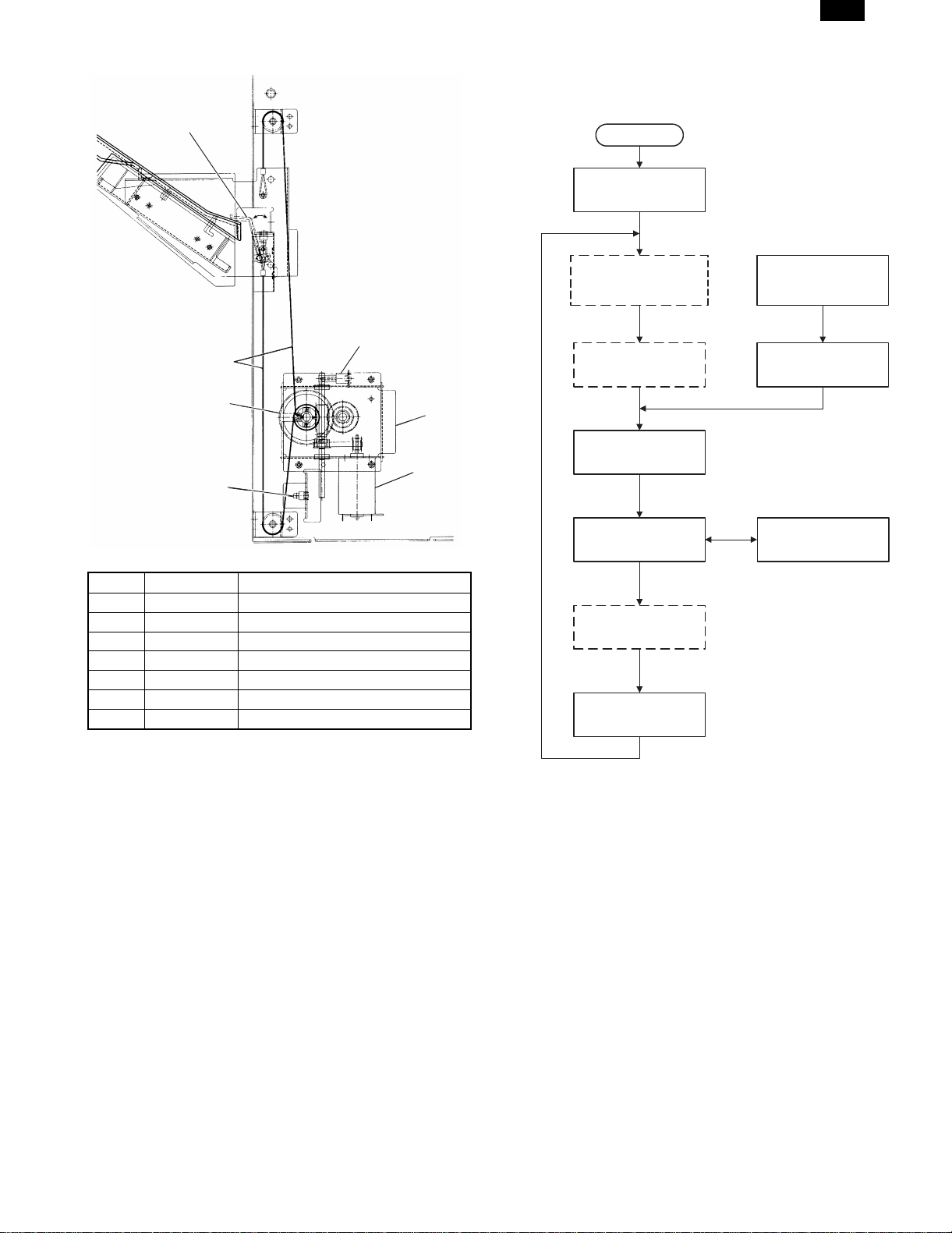
E. Elevator
1) Elevator motor (3)
When the elevator motor (3) is driven, the winding pulley (5) is rotated
in both forward and reverse to wind up the wire (6) stretching vertically so that the tray 3 (off-set tray) is moved up and down. This allows
the discharge of paper at a fixed position according to the number of
sheets to be loaded on the off-set tray.
2) Off-set tray full and load detection
When the power is turned ON, the off-set tray lowers to the lower limit
sensor (4) position. Then it elevates until the upper limit sensor (7)
turns ON, while counting the encoder pulses of the elevator motor (3).
The volume of paper loaded on the off-set tray is calculated (0 100%) by counting the number of pulses from the elevator encoder
(1).
The off-set tray is judged to be full when both the lower and upper
limit sensors (4), (7) are turned ON.
Staple unit moving
motor
8/19/1999 4 – 3
Page 13
(7)
AR-FN3
3. Basic operation
A. Basic operation flowchart
Power ON
Initialization when
powered on
(1)
(6)
(5)
(4)
No. Signal name Part name
(1) — Elevator motor encoder
(2) — Elevator drive unit
(3) EVM Elevator motor
(4) T3DN Tray 3 lower limit sensor
(5) — Winding pulley
(6) — Wire
(7) T3UP Tray 3 upper limit sensor
(3)
(2)
Independent movement
of staple unit
(Staple position)
Independent shifting
(Offset tray)
JOB_START
Transfer
Off-set tray paper
discharge
JOB_END
Operation when
JAM error occurs
Operation when
door is closed
Stapling
Fig. 1 Basic operation flowchart
1) Initialization
The finisher is initialized (home positioning of each motor) at the
following timing.
• When the power is turned on.
• The finisher leaves the copier and when either of the top or bottom
doors are opened.
• When the copier start key is pressed (JOB_START):
• Recovery action is performed.
4 – 4 8/19/1999
Page 14

AR-FN3
[5] DISASSEMBLY AND ASSEMBLY
[Note]
• This section explains the procedure for disassembling and
reinstalling the unit. Reinstall the unit in the reverse order of disassembly.
• Disassemble the unit in numerical order in each sketch.
• This section covers the procedure for disassembling the following
major parts. For the other parts, refer to the Parts Guide.
No. Part name
1 Main drive motor
2 Staple unit movement motor
3 Elevator motor
4 Off-set motor
5 Stapler
6 Jogger motor
7 Pusher motor
8 Elevator wires, top and bottom
9 Paper discharge roller 3
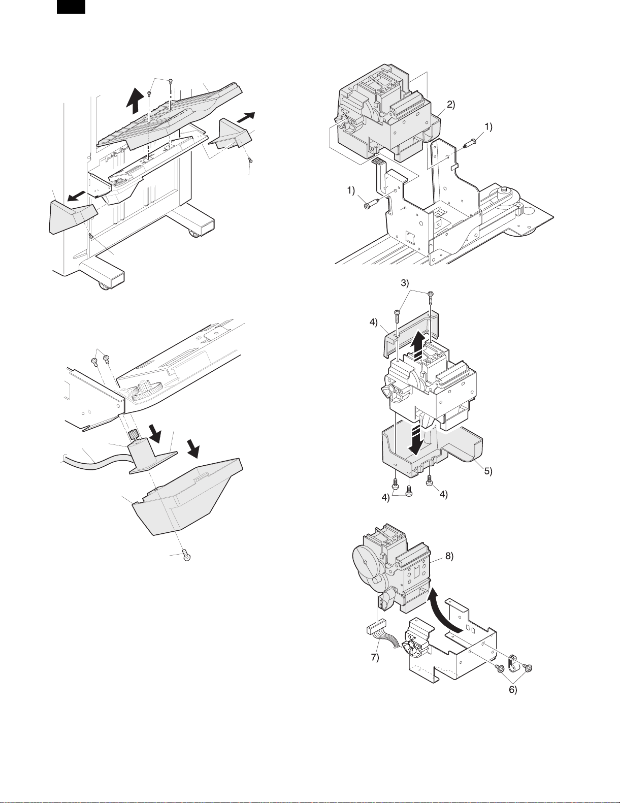
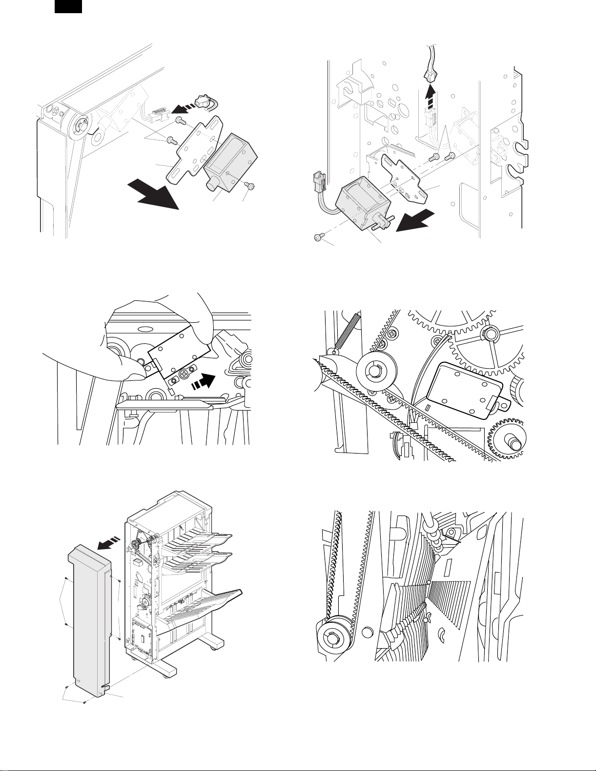
1. Main drive motor
2. Staple unit movement motor
1)
1)
3)
2)
1)
2)
1)
2)
3)
1)
4)
8/19/1999 5 – 1
Page 15

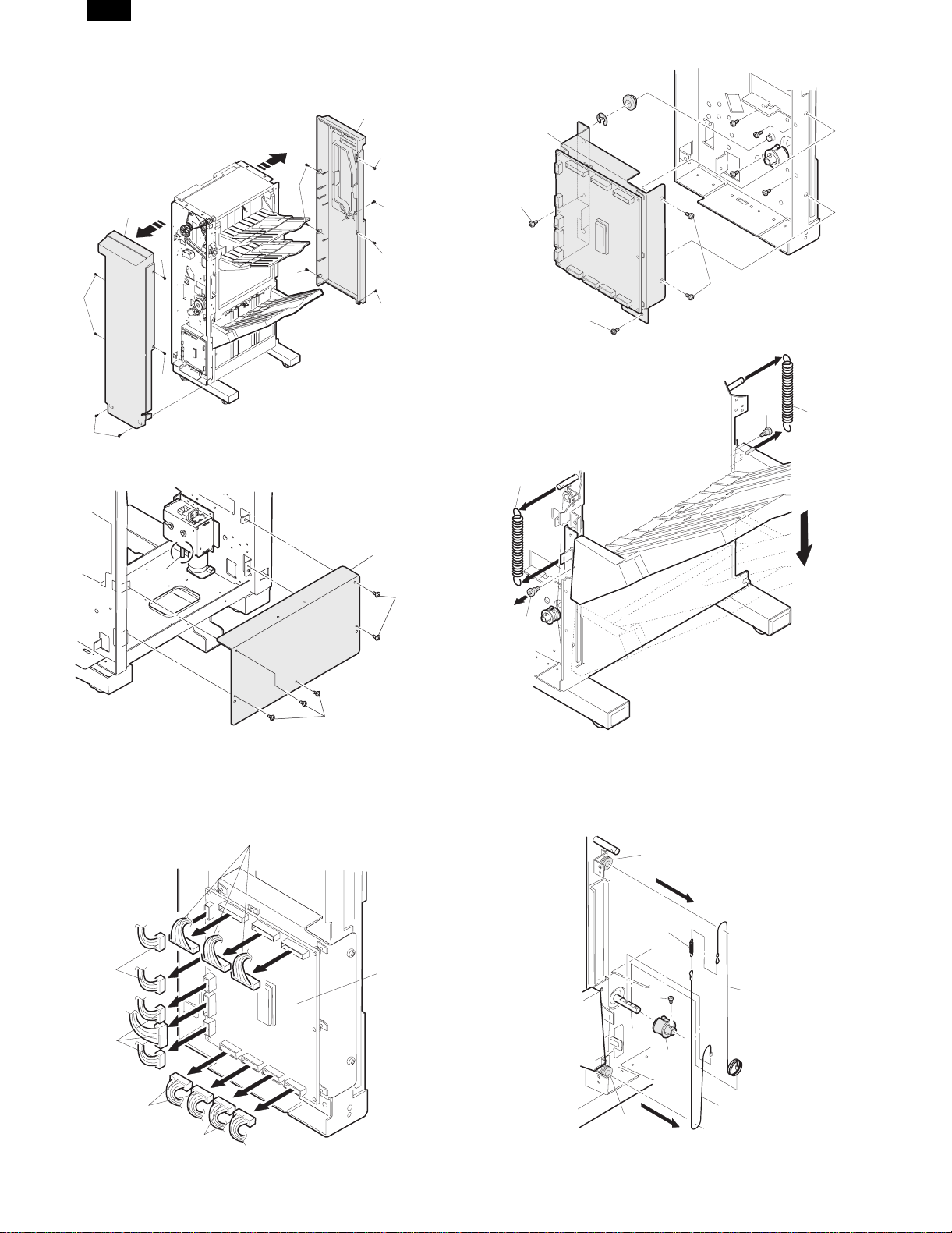
3. Elevator motor
AR-FN3
12)
11)
2)
3)
1)
4)
8)
9)
10)
13)
13)
8)
8)
14)
[Note] Before removing the lower cover on the FN3, make sure the
tray 3 is at the upper limit position.
If the tray 3 is not at the upper limit position, turn the knurled
part on the shaft (A) in the sketch and move the tray 3 to the
upper limit.
7)
7)
7)
7)
7)
15)
16)
A
[Note] When setting the elevator motor 16), pay attention to the
direction of the filter PWB A. For the direction, see the sketch
given above.
5 – 2 8/19/1999
Page 16
AR-FN3
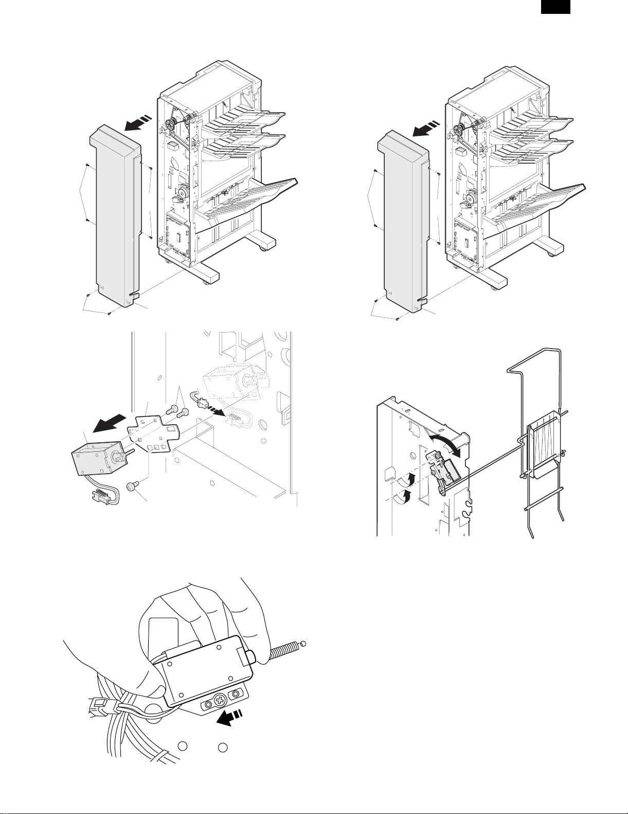
4. Off-set motor
6)
5)
1)
5. Stapler
2)
4)
3)
8)
A
9)
B
7)
6)
[Note] When setting the tray 3 cover (bottom), use caution not to get
the wire caught in the harness B.
When setting the off-set motor 9), pay attention to the filter
PWB A. For the direction, see the sketch given above.
8/19/1999 5 – 3
Page 17

AR-FN3
6. Jogger motor
7. Pusher motor
3)
3)
4)
3)
3)
3)
3)
3)
4)
3)
3)
3)
6)
6)
7)
[Note] When installing the jogger motor 6), pay attention to the har-
ness pulling-out direction. See the sketch given above.
9)
8)
5 – 4 8/19/1999
6)
8)
Page 18
AR-FN3
8. Elevator wires, top and bottom
2)
2)
3)
(A)
1)
1)
5)
5)
6)
8)
4)
5)
4)
5)
7)
10)
12)
11)
10)
10)
13)
12)
7)
[Note] If the tray 3 is not at the upper limit position, turn the knurled
part on the shaft (A) in the sketch and move tray 3 to the
upper limit position.
8)
8)
9)
8)
13)
[Note] Remove the two screws 13) and:
1) Move the off-set tray to the lower limit position.
2) Turn the knurled part on the elevator worm gear shaft under the
elevator drive box so that the D-cut surface on the winding pulley
points upward.
C
14)
17)
15)
A
18)
8)
8)
8/19/1999 5 – 5
16)
B
[Note] Remove the elevator wires (top, bottom) at the rear frame
side in the same manner.
Page 19
[Reinstalling elevator wires (top, bottom) at the front
frame side]
1) Insert both the top elevator wire 15) and bottom elevator wire 16)
into the elevator pulley drive shaft A. Secure the winding pulley
18) with the screw 17).
2) Hook the bottom elevator wire 16) on the lower wire roller B from
the left side of the winding pulley 18), without giving extra winding.
With the wire extended upward, hook the wire mounting spring 14)
on the wire hook.
3) Wind the top elevator wire 15) onto the winding pulley 18) and turn
3 and 3/4 turns in the clockwise direction and hook on the upper
wire roller C. Hold it stretched downward.
4) When setting the top and bottom elevator wires at the rear frame
side (see the sketch below), observe the following conditions:
[Note] Observe the following conditions when setting elevator-wires
(top and bottom) at the rear frame side. See the sketch below.
• The bottom elevator wire 16) should be hooked onto the
bottom wire roller B from the right side of the winding pulley
18) without giving extra winding.
• The top elevator wire 15) should be wound onto the winding
pulley 18) 3 and 3/4 turns in the counterclockwise direction.
C
AR-FN3
14)
15)
17)
A
18)
16)
B
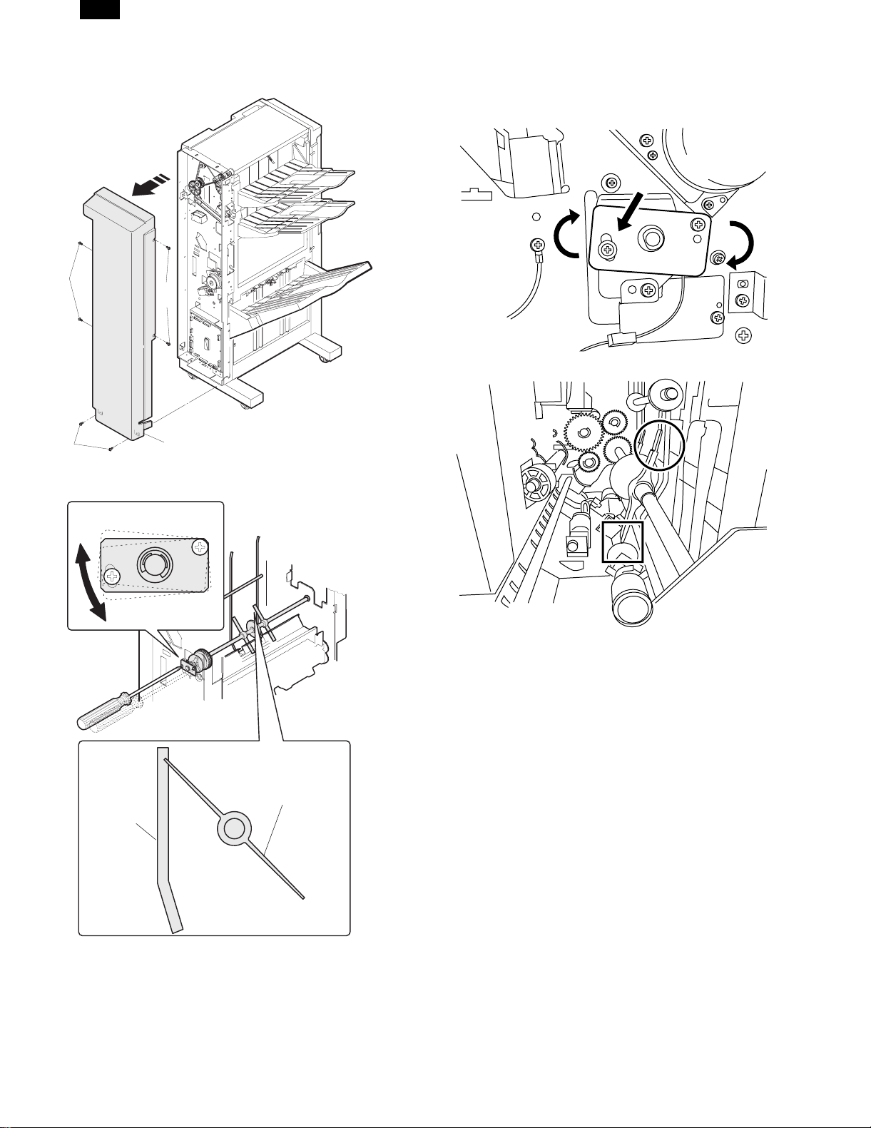
9. Paper discharge roller 3
9-1. Paper discharge roller 3 (top)
[Note] After removing the E-ring, slide the bearing A in the direction
A to remove the paper discharge roller 3.
9-2. Paper discharge roller 3 (bottom)
5 – 6 8/19/1999
Page 20

AR-FN3
15)
15)
16)
15)
15)
8/19/1999 5 – 7
Page 21

[6] ADJUSTMENTS
The following table shows the main parts requiring adjustment at the
time of replacement
Item Part name
1 Jogger F/R
2 Paper discharge gate solenoid 1
3 Paper discharge gate solenoid 2
4 Paper discharge gate solenoid 3
5 Paper holding solenoid
6 Paddler clutch
7 Vertical transport de-curler
Note: Remove or install parts in numerical order shown in the follow-
ing figures.
1. Jogger F/R
A. Let the unit staple 5 sheets of A4 or letter paper and check the
bundle of the sheets for deviation in directions A).
A)
Letter position
AR-FN3
Jogger
Label
A
Jogger
A4 position
Pin
B. If the deviation in directions A) are within 1 mm, there is no need
to adjust the jogger F/R.
C. When the deviation exceeds 1 mm, adjust the jogger F/R accord-
ing to the simulation 3-6: Adjusting Finisher Jogger Position.
Sim. 3-6: Adjusting Finisher Jogger Position
The screen above is displayed after the sub number of the simulation
is entered.
1) Adjust the value with the numeric keypad.
2) The joggers in the finisher are operated by pressing the [EXECUTE] key. The [EXECUTE] key is displayed in reverse video
during loading operation. When the [EXECUTE] key in this state
is pressed, loading operation can be canceled.
Condition Adjusting procedure
1 When the
deviation in the
direction A)
exceeds 1 mm.
Note: The width between joggers can be visually checked by observ-
ing the label inside the staple tray.
Decrease the simulation value.
(Decreasing the simulation by 1 narrows
the width between the joggers by 0.63
mm.)
Increase the simulation value. (Increasing
the simulation value by 1 wi dens the w idth
between the joggers by 0.63 mm)
The spacing between
labels is 0.5 mm.
2. Paper discharge gate solenoid 1
2)
2)
3)
1)
2)
1)
2)
6 – 1 8/19/1999
Page 22
AR-FN3
5)
5)
6)
6)
7)
[Adjustment and precaution in setting]
Manually pull the plunger to move it in the arrow direction until it
stops, and fix it at that position.
4)
3. Paper discharge gate solenoid 2
4)
[Adjustment and precaution in setting]
Fit the edge of plate to which the solenoid is attached, with the left
edge of the marking.
At that time, check that the rib of the paper discharge gate 2 and the
rib inside the left cabinet 1 are aligned on a line as shown in the figure
with the solenoid pulled completely.
7)
2)
1)
2)
8/19/1999 6 – 2
3)
Page 23
AR-FN3
4. Paper discharge gate solenoid 3
2)
1)
2)
3)
5. Paper holding solenoid
2)
1)
2)
3)
5)
6)
7)
4)
[Adjustment and precaution in setting]
Paper discharge gate (OG3SL) adjustment procedures
Manually pull the plunger in the arrow direction until it stops, and fix it
at that po sition .
[Adjustment and note for setting]
Fix it at the center of the long hole.
6 – 3 8/19/1999
Page 24
AR-FN3
6. Paddler clutch
2)
1)
2)
3)
[Adjustment and note for setting]
Loosen the fixing screw (indicated with an arrow in the figure) of the
paddler adjustment plate, and turn the paddler adjustment plate in the
arrow direction and fix it.
Staple
movable
PG
8/19/1999 6 – 4
Paddler
Page 25
7. Vertical transport de-curler
[Process]
Use the vertical transport de-curler adjustment jig to adjust the nip
quantity.
1) Insert the marked section of the jig corresponding to each nip
quantity under the unit as shown below.
2) Insert the vertical transport de-curler adjustment jig until it makes
contact with the shaft.
3) Adjust with the set screw, and tighten the screw (S tight M3).
Perform the same procedures for F and R.
Check that the transport de-curler adjustment jig is smoothly inserted
on either side of F/R.
If the jig cannot be inserted smoothly, perform the adjustment and
check again.
Nip quantity (reference)
dimension between shafts
Inch series ❍
EX AB series ❍
Japan ❍
Transport de-curler adjustment jig
1.0 (5.0)
AR-FN3
Set screw
M3
Set screw
Insert Set screw
M3
Insert
6 – 5 8/19/1999
Page 26

AR-FN3
[7] MAINTENANCE
If reception is performed during maintenance work, it is very dangerous. Therefore, be sure to disconnect the power cable from the machine.
1. Main te nan ce syst em table
Name Work
Rollers Clean Maintenance service 80K or 2 years
Paper guides Clean Maintenance service 80K or 2 years
Gears Lubricate Grease Maintenance service 80K or 2 years
Belts Check Maintenance service 120K or 2 years
Sensors Check Maintenance service 80K or 2 years
Staple unit Replace Maintenance service 100K
Execution timing Cycle
Execution conditions
Note
8/19/1999 7 – 1
Page 27

(Rollers/Paper guides)
AR-FN3
7 – 2 8/19/1999
Page 28

AR-FN3
8/19/1999 7 – 3
Page 29

(Gears)
AR-FN3
Others (Sensors) (Belts)
7 – 4 8/19/1999
Page 30

AR-FN3
[8] TROUBLESHOOTING
1. T r ou ble code
Trouble
code
Main
Sub
code
code
F1 00 Content Finisher communication trouble
Detail Communication line test error occurs when
Cause Improper connection or broken wire of
Check
and
remedy
01 Content Finisher jogger shift trouble
Detail Jogger shift trouble
Cause Motor lock
Check
and
remedy
02 Content Finisher transport motor error
Detail Transport motor drive trouble
Cause Motor lock
Check
and
remedy
04 Content Finisher indexer lower limit detected
Detail Indexer has exceeded lower limit.
Cause Sensor defective
Check
and
remedy
05 Content Finisher elevator motor trouble
Detail Indexer has exceeded upper limit
Cause Sensor defective
Check
and
remedy
06 Content Finisher shift motor error
Detail Finisher shift motor trouble
Cause Motor lock
Check
and
remedy
F1 08 Content Finisher staple shift motor trouble
Detail Staple motor drive trouble
Cause Motor lock
Check
and
remedy
power is turned on or after the exit of a
simulation mode.
Improper communication with sorter
connector or harness between copier and
Finisher
Finisher control PWB defective
Control PWB (PCU) defective
Malfunction due to noise
Clear by turning the power supply OFF/ON.
Check communication line connector and
harness.
Replace Finisher control PWB or PCU PWB.
Motor rpm abnormality
Motor overcurrent
Finisher control PWB trouble
Check the jogger motor operation with SIM
3-3.
Check transport motor operation with
SIM3-3.
Finisher control PWB defective
Check sensor with SIM3-2.
Finisher control PWB defective
Check sensor with SIM3-2.
Improper motor speed
Overcurrent to motor
Finisher control PWB defective
Check shift motor operation with SIM3-3.
Motor RPM abnormality
Motor overcurrent
Finisher control PWB trouble
Check the staple motor operation with SIM
3-3.
Description
Trouble
code
Main
Sub
code
code
F1 10 Content Staple unit operation trouble
Detail Staple operation trouble
Cause Motor lock
Motor rpm abnormality
Motor overcurrent
Finisher control PWB trouble
Check
and
remedy
11 Content Pusher motor trouble
Detail Pusher motor trouble
Cause Motor lock
Check
and
remedy
15 Content Finisher elevator motor trouble
Detail Elevator motor trouble
Cause Motor lock
Check
and
remedy
17 Content ST paper exit roller pressure release trouble
Detail ST paper exit roller pressure release trouble
Cause ST paper exit roller pressure release clutch
Check
and
remedy
18 Content Tray 3 paper exit paddler operation trouble
Detail Tray 3 paper exit paddler operation trouble
Cause Tray 3 paper exit paddler solenoid
Check
and
remedy
80 Content Finisher power trouble
Detail 24V power is not supplied to the finisher
Cause Connector harness improper connection or
Check
and
remedy
Check the staple motor operation with SIM
3-3.
Motor rpm abnormality
Motor overcurrent
Finisher control PWB trouble
Check the pusher motor operation with SIM
3-3.
Motor rpm abnormality
Motor overcurrent
Finisher control PWB trouble
Check the elevator motor operation with
SIM 3-3.
when turning on the power/initializing
abnormality
ST paper exit roller pressure release clutch
HP sensor abnormality
Stop the transport motor in SIM 3-3, turn on
the STORCL to check that the pressure
release roller operates.
Check the STORHP sensor with SIM 3-2.
when turning on the power/initializing
abnormality
Tray 3 paper exit paddler HP sensor
abnormality
Finisher control PWB trouble
Operate the transport motor with SIM 3-3
and turn on T3PDSL to check that tray 3
paddler operates.
Check T3PDHP sensor with SIM 3-2.
PWB.
disconnection
Finisher control PWB trouble
Power unit trouble
Check the sensor operation with SIM 3-2.
Description
8/19/1999 8 – 1
Page 31

(1) Finisher does not operate. (excluding JAM
state)
1
AR-FN3
Is connection
cable properly
connected?
YES
+5V between
CNA-6 and CNA-5 of
main PWB?
YES
+24V between
CNA-1 and CNA-3 of
main PWB?
YES
Are
DSW1, 2, 3
signals of main PWB
OK?
YES
NO
NO
NO
NO
Connect connection
cable to body properly.
Check or replace harness
or check supply voltage.
Check or replace harness
or check supply voltage.
Check connections.
Check harnesses at
upper and lower surfaces
and harness leading to
upper transfer switch for
connections, and replace
if necessary.
Staple unit
moving motor rotates
normally?
YES
Pusher motor rotates
normally?
YES
Jogger motor rotates
normally?
YES
Check main PWB and
replace if necessary.
NO
NO
NO
4
4
4
Transfer motor
rotates normally?
YES
Elevator motor
rotates normally?
YES
Off-set motor
rotates normally?
YES
NO
NO
NO
2
3
3
8 – 2 8/19/1999
Page 32

AR-FN3
(2) Transport motor error (3) Elevator and off-set motor error
2
Is load on motor
shaft normal?
YES
Is motor winding
(between U, V, and W)
shorted?
NO
Is harness
connected normally?
YES
Check mechanical load
NO
and driving system.
Remove foreign matter.
YES
NO
Replace motor.
Connect harness
properly.
3
Is fuse blown out?
YES
Is load on motor
shaft normal?
YES
Is motor winding
shorted?
NO
NO
NO
YES
Replace fuse.
Check mechanical load
and driving system.
Remove foreign matter.
Replace motor.
Motor rotates
even slightly?
YES
Is motor
encoder output
normal?
YES
Check main PWB and
replace if necessary.
NO
NO
Check motor and
replace if necessary.
Is voltage
applied to motor
connector?
YES
NO
Is harness
connected normally?
YES
Motor rotates
even slightly?
YES
Is motor
encoder sensor output
normal?
YES
NO
NO
NO
Connect harness
applied on motor
Check motor and
replace if necessary.
mounting and replace
Check harness and
replace if necessary.
properly.
Is voltage
connector?
YES
Replace sensor
if necessary.
NO
8/19/1999 8 – 3
Check main PWB and
replace if necessary.
Page 33

AR-FN3
(4) Stepping motor error
4
Is load on motor
shaft normal?
YES
Is motor winding
shorted?
NO
Is harness connected
normally?
NO
YES
NO
Check mechanical
load and driving system.
Remove foreign matter.
Replace motor.
Connect harness
properly.
(6) Clutch and solenoid error
6
Is each
load properly
mounted?
YES
Conduction
between coils of each
load?
YES
Conduction
between connectors and
terminals?
NO
NO
NO
Check mounting and
replace if necessary.
Replace clutch or
solenoid.
Check harness and
replace if necessary.
Check main PWB and
replace if necessary.
(5) Sensor error
5
Is sensor
mounted properly?
Is harness connected
properly?
Replace main PWB.
YES
YES
Check sensor mounting
NO
and harness and replace
if necessary.
YES
Replace main PWB.
8 – 4 8/19/1999
Page 34

AR-FN3
[9] CIRCUIT DESCRIPTIONS
1. Outlin e
The finisher main circuit transmits and receives data to and from the
copier main PWB. According to instructions from the copier, it controls
loads, sensors and the input of switching information.
The finisher main circuit consists of a circuit which receives signals
from sensors and switches, a circuit which drives solenoids and
clutches, CPU, ROM, expansion I/O and other peripheral circuits.
2. Block diagram
The finisher block diagram is shown in Fig. 1.
F-TXD
RXD0
CPU(H8/3040)
TXD0
P95
P94
/RES
XTAL
EXTAL
MD0
MD1
MD2
P70
P71
P72
P74
P75
P77
P80
P81
PA0
PA6
Copier
Jogger motor HP sensor
Stapler self-printing sensor
Pusher motor HP sensor
Staple unit HP sensor
Tray 2 paper full sensor
Stapler needle
replacement sensor
Elevator motor encoder
Off-set HP sensor
Staple HP sensor
Trasport motor encoder
BUFF
IC14
+5V
X1
GND1
GND2
[Mode 1]
+24VIN
10V generating
circuit
ZD1,7,Q5
JGHP
READY
PSHP
STUHP
T2PF
STND
EVRE
OFHP
STHP
FMRE
F-RXD
F-DTR
F-DSR
F-RES
8MHz
"1"
"0"
"0"
+10V
IC2
PA4
PA7
P44
P45
PB0~3
P40~43
PB4~7
P60
P46
P47
A0~16
D0~7
CS0
WR
CS2
RD
FMPWM
FMDIR
OFMA
OFMB
* : A,B,A/,B/
RM*
STUM*
PM*
PMPD
PPSL
STSL
A0~16
D0~7
ROMCS
RD
WR
EXPCS
+10V
4
4
4
2-Phase brushless
motor drive circuit
IC10,16,20
DC brush motor
drive circuit
2-Phase stepping
motor constant-current
drive circuit
2-Phase stapping
motor constant current
drive circuit
2-Phase stapping
motor constant current
drive circuit
17
8
IC1
IC4
IC7
IC11
ROM(1M)
A0~16
DO~7
CS
OE
IC7
HU,HV,HW
Main drive motor
(FM)
[Brushless motor]
Ogg-set motor
(OFM)
[Brush motor]
Reversion motor
(RVM)
[Stepping motor]
Staple unit moving
motor (STUM)
[PM stepping motor]
Pusher motor
(PSM)
[HYB stepping motor]
Paper entry sensor
Reversion paper discharge sensor
Transport sensor 1
Transport sensor 2
Transport sensor 3
Transport sensor 4
Tray 3 paper discharge sensor
Staple tray paper entry sensor
Staple Paper detection sensor
Tray 1 paper full sensor
Staple tray paper entry sensor 2
Tray 3 upper limit sensor
Tray 3 lower limit sensor
Staple needle detection sensor
Staple cartridge sensor
Copier connection
switch
Upper door switch
Front door switch
INPD
RVPD
PFD1
PFD2
PFD3
PFD4
T3OD
STID
STPD
T1PF
STID2
T3UP
T3DN
LSTS
NCTS
+24VIN
F-RES
Level
conversion
circuit
ZD3,4,5,6
IC19
+24V
PWD
DSW1
DSW2
DSW3
EXPA0
EXPA1
EXPA3
EXPA4
EXPA5
EXPA6
EXPA7
EXPB0
EXPB1
EXPB2
EXPB3
EXPB4
EXPB5
EXPB6
EXPB7
EXPG0
EXPG1
EXPG2
EXPG3
RES
EXP(M66500F)
IC3
D0~7
A0~2
EXPE4
EXPE5
EXPE0
EXPE1
ECPC0~3
EXPF0
EXPF1
EXPF2
EXPF3
EXPF4
EXPF
EXPF6
EXPF7
EXPC4
EXPC5
EXPC6
EXPC7
CS
WR
RD
5
EXPCS
WR
RD
D0~7
A
~
02
STMA
STMB
EMA
EMB
4
JM*
INGSL
T3UPSL
OG1SL
OG3SL
RRSL
T30RCL1
PDCL
STORCL
SPSL
T12CL
OG2SL
T3SLCL
PPSL
STSL
Main PWB
DC brush motor
drive circuit (H driver)
IC9,Q1,2,3,4
DC brush motor
drive circuit (H driver)
IC12,13
2-phase stepping
motor constant current
drive circuit IC8
Solenoid/
clutch
drive
circuit
IC17,18
Solenoid/
clutch
drive
circuit
IC5
Staple motor (STM)
[Brush motor]
Elevator motor (EVM)
[Brush motor]
Jogger motor (JGM)
[PM stepping motor]
Paper entry gate solenoid
Tray 3 upper limit solenoid
Paper discharge gete solenoid
Paper discharge gate 3 solenoid
Reversion roller pressure release SL
Tray 3 paper exit roller clutch
Paddler clutch
ST paper discharge roller
Pressure release clutch
Short path switching SL
Tray 1/2 speed change clutch
Paper discharge gate 2 solenoid
Tray 3 low speed clutch
Staple tray solenoid
Staple tray solenoid
Stapler
Fig. 1 3 tray finisher block diagram
9/2/1999 9 – 1
Page 35

3. CPU (HB/3040)
A. Outline
The CPU (IC3) controls finisher loads and the system synchronously,
transmitting and receiving data to and from the copier main PWB
through the serial communication line.
B. Features
The H8/3040 is a high-performance single chip microprocessor using
the 32-bit H8/300H CPU as a core, integrating peripheral functions
necessary for system configuration.
The H8/300H CPU has an internal 32-bit configuration and is
equipped with 16-bit × 16 general-purpose registers and a simple,
optimized instruction set for high-speed operation. It can handle 16M
byte linear address space.
As peripheral functions, it contains ROM, RAM, 16-bit integrated timer
unit (ITU), programmable timing patter controller (TPC), watchdog
timer (WDT), serial communication interface (SCI), A/D converter,
D/A converter, I/O port, DMA controller (DMAC), and refresh controller.
C. Terminal connection diagram
AR-FN3
A Vcc
Vref
P70/AN0
P71/AN1
P72/AN2
P73/AN3
P74/AN4
P75/AN5
P76/AN6/DA0
P77/AN7/DA1
A Vss
P80/RFSH/IRQ0
P81/CS3/RAS/IRQ1
P82/CS2/IRQ2
P83/CS1/IRQ3
P84/CS0
Vss
PA0/TP0/TEND0/TCLKA
PA1/TP1/TEND1/TCLKB
PA2/TP2/TIOCA0/TCLKC
PA3/TP3/TIOCB0/TCLKD
PA4/TP4/TIOCA1/A23
PA5/TP5/TIOCB1/A22
PA6/TP6/TIOCA2/A21
PA7/TP7/TIOCB2/A20
EXTAL
Vss
NMI
RES
656463
Vss
TXD0/P90
STBY
62
61
TXD1/P91
RXD0/P92
RXD1/P93
P65/HWR
706968
71
Vcc
66L
67
H8/3040
RES0
P66/LWR
MD2
74 MD1
MD0
72
75
74
76
77
78
79
80
81
82
83
84
85
86
87
88
89
90
91
92
93
94
95
96
97
98
99
100
73
12345678910111213141516171819202122232425
Vcc
XTAL
P64/RD
P63/AS
Vss
P61/BREQ
P62/BACK
P60/WAIT
57
605958
D0/P40
P53/A19
56 5554
D1/P41
D2/P42
P52/A18
P51/A17
P50/A16
53 5251
Vss
D3/P43
D4/P44
P27/A15
P26/A14
50
49
48
47
46
45
44
43
42
41
40
39
38
37
36
35
34
33
32
31
30
29
28
27
26
D5/P45
D6/P46
A13/P25
A12/P24
A11/P23
A10/P22
A9/P21
A8/P20
Vss
A7/P17
A6/P16
A5/P15
A4/P14
A3/P13
A2/P12
A1/P11
A0/P10
Vcc
D15/P37
D14/P36
D13/P35
D12/P34
D11/P33
D10/P32
D9/P31
D8/P30
D7/P47
TIOCA3/TP8/PB0
TIOCB3/TP9/PB1
TIOCA4/TP10/PB2
TIOCB4/TP11/PB3
TOCXA4/TP12/PB4
TOCXB4/TP13/PB5
IRQ4/SCK0/P94
DREQ0/TP14/PB6
ADTRG/DREQ1/TP15/PB7
IRQ5/SCK1/P95
9 – 2 8/19/1999
Page 36

AR-FN3
D. CPU: H8/3040 (IC3) terminal signals
Pin
No.
1 VCC VCC Power supply (+5V)
2 PB0 T3OMA OUT H Tray 3 paper discharge motor drive signal A
3 PB1 T3OMA/ OUT H Tray 3 paper discharge motor drive signal A/
4 PB2 T3OMB OUT H Tray 3 paper discharge motor drive signal B
5 PB3 T3OMB/ OUT H Tray 3 paper discharge motor drive signal B/
6 PB4 PMA OUT H Pusher motor drive signal A
7 PB5 PMA/ OUT H Pusher motor drive signal A/
8 PB6 PMB OUT H Pusher motor drive signal B
9 PB7 PMB/ OUT H Pusher motor drive signal B/
10 /RES0 RES0/ OUT L External device reset signal
11 VSS GND Power supply (GND)
12 P90 F-RXD OUT UART output
13 P91 N.C
14 P92 F-TXD IN UART input
15 P93 N.C
16 P94 F-DSR OUT H DSR signal output to copier (communication request at H)
17 P95 F-DTR IN H DTR signal input from copier (communication permission at H)
18 P40 STUMA OUT H Staple unit movement motor drive signal A
19 P41 STUMA/ OUT H Staple unit movement motor drive signal A/
20 P42 STUMB OUT H Staple unit movement motor drive signal B
21 P43 STUMB/ OUT H Staple unit movement motor drive signal B/
22 VSS GND Power supply (GND)
23 P44 OFMA OUT H Off-set motor CCW drive signal
24 P45 OFMB OUT H Off-set motor CW drive signal
25 P46 N.C
26 P47 N.C
27 P30 D0 IN/OUT Data signal (D0)
28 P31 D1 IN/OUT Data signal (D1)
29 P32 D2 IN/OUT Data signal (D2)
30 P33 D3 IN/OUT Data signal (D3)
31 P34 D4 IN/OUT Data signal (D4)
32 P35 D5 IN/OUT Data signal (D5)
33 P36 D6 IN/OUT Data signal (D6)
34 P37 D7 IN/OUT Data signal (D7)
35 VCC VCC Power supply (+5V)
36 P10 A0 OUT Address signal (A0)
37 P11 A1 OUT Address signal (A1)
38 P12 A2 OUT Address signal (A2)
39 P13 A3 OUT Address signal (A3)
40 P14 A4 OUT Address signal (A4)
41 P15 A5 OUT Address signal (A5)
42 P16 A6 OUT Address signal (A6)
43 P17 A7 OUT Address signal (A7)
44 VSS GND Power supply (GND)
45 P20 A8 OUT Address signal (A8)
46 P21 A9 OUT Address signal (A9)
47 P22 A10 OUT Address signal (A10)
48 P23 A11 OUT Address signal (A11)
49 P24 A12 OUT Address signal (A12)
50 P25 A13 OUT Address signal (A13)
51 P26 A14 OUT Address signal (A14)
52 P27 A15 OUT Address signal (A15)
53 P50 A16 OUT Address signal (A16)
54 P51 A17 OUT Address signal (A17)
55 P52 A18 OUT Address signal (A18)
56 P53 A19 OUT Address signal (A19)
57 VSS GND Power supply (GND)
58 P60 PMPD OUT H Pusher motor power down signal (power down at H)
59 P61 JMPD OUT H Jogger motor power down signal (H: Power down)
60 P62 T3MPD OUT H Tray 3 paper discharge motor power down signal (H: Power down)
61 S-CLK S-CLK OUT System lock signal
62 /STBY STBY/ IN L Stand-by signal (fixed at H level)
63 /RES RES/ IN L Reset signal (reset at L)
64 NMI NMI IN H Non-maskable interruption (fixed at L level)
65 VSS GND Power supply (GND)
66 EXTAL EXTAL IN Clock (12.2MHz)
67 XTAL XTAL IN Clock (12.2MHz)
68 VCC VCC Power supply (+5V)
Port
Signal
name
IN/OUT ACTIVE Specification Remarks
8/19/1999 9 – 3
Page 37

AR-FN3
Pin
No.
69 P63 AS/ OUT H Address strobe signal
70 P64 RD/ OUT L ROM, I/O read signal (read at L)
71 P65 HWR/ OUT L Upper write signal (write at L)
72 P66 LWR/ OUT L Lower write signal (write at L)
73 MD0 MD0 IN Mode setting signal 0 (fixed at H level)
74 MD1 MD1 IN Mode setting signal 1 (fixed at L level)
75 MD2 MD2 IN Mode setting signal 2 (fixed at L level)
76 AVCC AVCC A/D, D/A converter power supply
77 VREF VREF A/D, D/A converter reference voltage
78 P70 JGHP IN H Jogger motor home position signal (home position at H)
79 P71 READY/ IN L Stapler self-priming signal (ready at L)
80 P72 PSHP IN H Pusher motor home position signal (home position at H)
81 P73 STORHP/ IN L
82 P74 STUHP IN H Stapler unit home position signal (home position at H)
83 P75 T2PF/ IN L Tray 2 paper full sensor signal (full at L)
84 P76 N.C ST pressure release home position signal (L: Pressure applied)
85 P77 STND IN L Stapler needle replacement sensor (needle being replaced at L)
86 AVSS GND Power supply (GND)
87 P80 EVRE IN Elevator motor encoder
88 P81 OFHP IN H Off-set tray home position signal (home position at H)
89 P82 EXPCS/ OUT L Expansion I/O chip select signal (select at L)
90 P83 N.C
91 P84 ROMCS/ OUT L ROM chip select signal (select at L)
92 VSS GND Power supply (GND)
93 PA0 STHP/ IN L Stapler home position signal (home position at L)
94 PA1 N.C
95 PA2 N.C
96 PA3 N.C
97 PA4 FMPWM/ OUT L Transport motor control signal (PWM output)
98 PA5 N.C
99 PA6 FMRE IN H Transport motor encoder signal
100 PA7 FMDIR OUT L Transport motor direction control signal (CW at L)
Port
Signal
name
IN/OUT ACTIVE Specification Remarks
4. Expansion I/O (M66500FP)
A. Outline
The expansion I/O converts data from the CPU into load control
signals and input signals from sensors and switches into data for the
CPU.
The expansion I/O uses the M66500FP.
B. Features
• I/Os are expandable up to 44 bits
(8-bit I/O port × 3, 8-bit high-dielectric output port × 2, 4-bit input
port × 1)
• Directly connectable to 12 MHz CPU without weight
• Writable to output port in input mode
• Output terminal status can be read from CPU
• Possible to drive transistor array
• 24 mA high-dielectric output port (16 bits) is incorporated.
• TTL level terminal at CPU side
• I/O terminal is CMOS level schmitt trigger input
C. Terminal connection diagram
64 PF5
63 PF4
62 PF3
61 PF2
60 PF1
56 PG2
59 PF0
58 GND2
57 PG3
55 PG1
PF6
PF7
Vcc
PE0
PE1
PE2
PE3
PE4
PE5
PE6
PE7
GND3
PB0
PB1
PB2
PB3
PB4
PB5
PB6
1
2
3
4
5
6
7
8
9
10
11
12
13
14
15
16
17
18
19
2021222324252627282930
M66500FP
54 PG0
53 PC3
52 PC2
51
50
49
48
47
46
45
44
43
42
41
40
39
38
37
36
35
34
33
31
32
PC1
PC0
PC4
PC5
PC6
PC7
D7
D6
D5
D4
D3
D2
D1
D0
A0
A1
A2
GND1
RESET
PB7
PA7
PA6
PA5
PA4
PA3
PA2
PA1
PA0
Vcc
CS
RD
WR
9 – 4 8/19/1999
Page 38

AR-FN3
D. Expansion I/O: M66500FP (IC11) terminal signals
Pin
No.
10 PE6 N.C
11 PE7 N.C
12 GND GND Power supply (GND)
13 PB0 STID/ IN L Staple tray paper entry sensor signal (On at L)
14 PB1 STPD/ IN L Staple tray paper sensor signal (On at L)
15 PB2 T1PF/ IN L Tray 1 paper full sensor signal (On at L)
16 PB3 STID IN L Staple tray paper entry sensor 2 signal (ON at L)
17 PB4 T3UP IN H Tray 3 upper limit sensor signal (On at H)
18 PB5 T3DN IN H Tray 3 lower limit sensor signal (On at H)
19 PB6 LSTS/ IN L Stapler needle sensor signal (presence of needle at L)
20 PB7 NCTS/ IN L Stapler cartridge sensor signal (presence of cartridge at L)
21 PA7 T3OD/ IN L Tray 3 paper discharge sensor signal (On at L)
22 PA6 PFD4/ IN L Transport sensor signal 4 (On at L)
23 PA5 PFD3/ IN L Transport sensor signal 3 (On at L)
24 PA4 PFD2/ IN L Transport sensor signal 2 (On at L)
25 PA3 N.C
26 PA2 N.C
27 PA1 T3PDHP/ IN L Paper discharge paddler home position sensor signal (L: HP)
28 PA0 INPD/ IN L Paper entry sensor signal (On at L)
29 VCC VCC Power supply (+5V)
30 /RD RD/ IN L Data read signal (read at L)
31 /WR WR/ IN L Data write signal (write at L)
32 /CS CS/ IN L Chip select signal (select at L)
33 RESET RESET IN H Reset signal (reset at H)
34 GND GND Power supply (GND)
35 A2 A2 IN Address signal (A2)
36 A1 A1 IN Address signal (A1)
37 A0 A0 IN Address signal (A0)
38 D0 D0 IN/OUT Data signal (D0)
39 D1 D1 IN/OUT Data signal (D1)
40 D2 D2 IN/OUT Data signal (D2)
41 D3 D3 IN/OUT Data signal (D3)
42 D4 D4 IN/OUT Data signal (D4)
43 D5 D5 IN/OUT Data signal (D5)
44 D6 D6 IN/OUT Data signal (D6)
45 D7 D7 IN/OUT Data signal (D7)
46 PC7 STPDSL OUT H Paddler solenoid in staple tray (H: ON)
47 PC6 OG2SL OUT H Paper discharge gate 2 solenoid (On at H)
48 PC5 T3PDSL OUT H Paper exit paddler solenoid (H: ON)
49 PC4 N.C
50 PC0 JMA OUT H Jogger motor drive signal A
51 PC1 JMA/ OUT H Jogger motor drive signal /A
52 PC2 JMB OUT H Jogger motor drive signal B
53 PC3 JMB/ OUT H Jogger motor drive signal /B
54 PG0 PWD IN H Power supply shut-off monitoring signal (power shut-off at H)
55 PG1 DSW1 IN H Connection to copier detection signal (disconnection at H)
56 PG2 DSW2 IN H Upper door opening and closing detection signal (door open at H)
57 PG3 DSW3 IN H Front door opening and closing detection signal (door open at H)
58 GND GND Power supply (GND)
59 PF0 N.C
60 PF1 N.C
61 PF2 OG1SL/ OUT L Paper discharge gate 1 solenoid drive signal (On at L)
62 PF3 OG3SL/ OUT L Paper discharge gate 3 solenoid drive signal (On at L)
63 PF4 N.C
64 PF5 T30RCL/ OUT L Tray 3 high speed clutch drive signal (On at L)
Port
1 PF6 PDCL/ OUT L Paddler clutch drive signal (On at L)
2 PF7 STORCL/ OUT L Paper discharge roller pressure release clutch (On at L)
3 VCC VCC Power supply (+5V)
4 PE0 EMA OUT H Elevator motor CW drive signal
5 PE1 EMB OUT H Elevator motor CCW drive signal
6 PE2 N.C
7 PE3 N.C
8 PE4 STMA OUT H Staple motor CW drive signal
9 PE5 STMB OUT H Staple motor CCW drive signal
Signal
name
IN/OUT ACTIVE Specifications Remarks
8/19/1999 9 – 5
Page 39

5. Communication buffer and reset circuit
In the communication buffer circuit, the transmission signal (F-TXD)
and communication permit signal (F-DTR) from the copier are
received by the buffer IC 74HC14 (IC101), while the reception signal
(F-RXD) and communication request signal (F-DSR) transmitted from
the finisher to the copier are outputted from the transistor Q101 and
Q102.
+5V
AR-FN3
The reset signal from the copier is also received by the IC101 and
inputted to the CPU’s reset terminal (active at L). In addition, the
reversion signal is inputted to the expansion I/O reset terminal (active
at H). For each signal, a protective diode is inserted between +5V and
GND.
F-TXD
F-RXD
F-DTR
F-DSR
F-RES
R113
4.7K
R115
1K
+5V
+5V
0.1U
+5V
R125
4.7K
RT1N141C
Q101
10K
RT1N141C
Q102
10K
R1264.7K
10K
R114
4.7K
10K
C118 0.1U
C117 1000p
C120 1000p
IC101
89
74HC14
IC101
6
5
74HC14
IC101
12
74HC14
10 11
IC101
74HC14
IC101
74HC14
C131
0.1U
F-TXD
F-RXD
F-DTR
F-DSR
from Copier
Signal
name
Description Logic (connector level)
F-TXD Signal line from copier to finisher Start bit detection at H
Usual (marking state) at L
F-RXD Signal line from finisher to copier Start bit detection at L
Usual (marking state) at L
F-DTR Status display signal line for the signal showing communication permit
from finisher to copier
F-DSR Status display signal line for the signal showing communication request
from finisher to copier
Communication from finisher to copier is inhibited at H
Communication from finisher to copier is permitted at L
No communication request from finisher to copier at H
Communication request from finisher to copier at L
F-RES Hard rest signal from copier Reset at H
Reset is released at L
RES/
RES
14
12
17
16
63
33
RXD0/P92
TXD0/P90
P95
P94
RES
CPU
(IC03)
RESET
I/O
(IC11)
6. Sensor input circuit
The signal from each sensor connected to 10 kohm pull-up resistance
and noise-removing 1000 pF capacitor, and connected through 10
kohm protective resistance to CPU, and expansion I/O Schmitt trigger
input port.
H.P.sensor
*1
AMP
*1:Rated Voltage Sircuit
Transport system sensor
240
The sensor signal for transport system is input to the schmitt trigger
input port because the sensor input circuit is not provided with rectifier
circuit.
+5V
+5V
+5V
+5V
10K
10K
10K
1000PF
*2 Schumit trigger input port
10K
1000PF
PA or PB
I/O
(IC03)
(IC02)
2
P**
CPU
9 – 6 8/19/1999
Page 40

AR-FN3
7. Switch input circuit
This circuit checks whether the finisher is connected to the copier,
both the top and front doors are opened. It is connected to microswitches whose contacts are closed when the finisher is connected to
the copier or the doors are closed.
Each switch is connected in series from +24V so that it becomes a
power supply switch for the drive. That is, +24V is conducted only
when all the 3 microswitches are closed.
When the finisher is connected to the copier, the microswitch turns
on, letting +24V be applied to ZD4. This allows electric current to flow
to the base resistance of the transistor array TD62504 (IC102), thus
turning on the transistor to change the expansion I/O PG1 (DSW1
signal) to L level.
Power supply +24V
Upper
Copier connection SW
+24V
+24V1
+24V1
ZD05
RD6.2EB2
ZD04
RD6.2EB2
When the finisher is disconnected from the copier, the transistor is
turned off to change the expansion I/O PG1 to H level. ZD4 (RD6.2E)
has a threshold level preset, to increase detection speed when the
supply of +24V is cut off. The levels of PG2 and 3 (DSW2, 3 signals)
also change when the top and front door switch is opened and
closed.
In addition, when +24V power supply from the copier is cut off, the
expansion I/O PG0 (PWD signal) level changes at the above circuit.
+5V
ZD03
RD6.2EB2
ZD06
RD6.2EB2
+24V3
to each motor and
solenoid clutch
Upper door SW
Lower
Front door SW
Microswitch x 3
Normal: SW ON
Copier separated
or door open: SW OFF
+24V2
+24V2
+24V3
Here are logic’s at the time of the power supply from the copier being
cut off and the doors opening and closing being detected.
←Upper Lower→
Expansion
Status
I/O port
Signal
name
Power supply from
copier is cut off
Disconnected from
copier
PG0 PG1 PG2 PG3
Remarks
PWD DSW1 DSW2 DSW3
H d.c d.c d.c
L H d.c d.c
Upper door open L L H d.c
Front door open L L L H
H: Power supply cut off (door open)
L: Conducting (door closed)
d.c: Unknown (no status is shown because power is cut off at
upstream)
PWD1
DS1
DS2
DS3
2
3
4
5
6
7
8
IC102
GND
I1
I2
I3
I4
I5
I6
I7
COM
TD62504F
O1
O2
O3
O4
O5
O6
O7
BR7
6
10K
2345
16
15
14
13
12
11
10
9
PWD1 54
DSW1 55
DSW2 56
DSW3 57
PG0
PG1
PG2
PG3
I/O
(IC03)
8/19/1999 9 – 7
Page 41

8. Solenoid and clutch drive circuit
The solenoid and clutch drive circuit uses non-inversion transistor
arrays TD62318AP (IC09, 12) which turn on the solenoids and
clutches when the input signal is at L; and an inversion transistor
array M63823P (IC14) which turns on the solenoids and clutches
when the input signal is at H.
IC14
PC4
PC5
PC6
PC7
PF0
PF1
PF2
PF3
PF4
PF5
PF6
PF7
I/O
(IC11)
49
48 T12CL
47 OG2SL
46 STPDSL
59
60
61 OG1SL/
62 OG3SL/
63
64 T3PDSL/
1 PDCL/
2 STORCL/
IC03(CPU)P46 PPSL
IC03(CPU)P47 STSL
1
I1
2
I2
3
I3
4
I4
5
I5
6
I6
7
I7
8
GND
M63823P
IC09
3
I1
6
I2
11
I3
14
I4
4
5
12
13
TD62318AP
IC12
3
6
11
14
4
GND
5
GND
12
GND
13
GND
TD62318AP
GND
GND
GND
GND
I1
I2
I3
I4
COM
COM1
COM2
VCC1
VCC2
COM1
COM2
VCC1
VCC2
The expansion I/O PG port which controls the solenoids and clutches
is an open collector type which becomes high impedance when resetting and H output. For this reason, to turn on the solenoids and
clutches at L level, the non-inversion type TD62318AP is used for
driving the PG port. On the other hand, the expansion I/O’s PC port is
at L level at resetting. For this reason, for driving the PC port, the
inversion type M63823P which turns on the solenoids and clutches at
H level is used.
+24V
9
+24V
16
O1
15
O2
14
O3
13
O4
12
O5
11
O6
10
O7
2
O1
7
O2
10
O3
15
O4
16
9
1
8
2
O1
7
O2
10
O3
15
O4
16
9
1
8
ZD01
+5V
ZD02
+5V
RD16FB
RD16FB
T12CL/
OG2SL/
STPDSL/
PPSL/
STSL/
OG1SL/
OG3SL/
+24V
T3PDSL/
PDCL/
STORCL/
+24V
+24V
+24V
T12CL
OG2SL
STPDSL
PPSL
PPSL
OG1SL
OG3SL
T3PDSL
PDCL
STORCL
AR-FN3
9. Jogger motor drive circuit
The jogger motor control signal (JMA, A/, B. B/) from the expansion
I/O (IC11) is input into the driver IC SLA7024MT, to drive the jogger
stepping motor which aligns the sheets sideways.
The driving method is unipolar, 1-2 phase excitement, constant-voltage method.
P61
CPU
(IC03)
(IC11)
Here is the driving pattern for the jogger motor.
Alignment direction Stop Opening direction
JMA
JMB
JMA/
JMB/
I/O
PC0
PC1
PC2
PC3
59
IC102
50
51
52
53
+5V
TD62504F
611
R139
200
JGMA
JGMA/
JGMB
JGMB/
R133
910
R135
100
C131
0.1U
R08
R134
R136
R09
1(1W)
2.4K
2.4K
1(1W)
C133
2200P
C132
2200P
+5V
R137
R132
C134
47K
470P
C130
470P
47K
IC06
2
TDA
13
TDB
9
RSA
3
REFA
14
REFB
10
RSB
6
IN A
5
IN/A
17
IN B
16
IN/B
SLA7024MT
+24V
C04
47u/35
7
VSA
12
VSB
1
OUT A
8
OUT/A
11
OUT B
18
OUT/B
4
GA
15
GB
Here is the driving pattern for the jogger motor.
+24V
V
JGMA
JGMA/
JGMB
JGMB/
JGM
+24V
9 – 8 8/19/1999
Page 42

AR-FN3
10. Pusher, reversion, staple unit moving
motor drive circuit
The pusher motor control signal (PMA, A/, B, B/), reversion motor
control signal (RMA, A/, B, B/) and staple unit movement motor control signal (STUMA, A/, B, B/) from the CPU (IC3) are inputted to the
stepping motor driver IC SLA7024M (IC4, 8, 10), to drive the following
motors : th e pu sher mo tor which ele vate s the pa per i ns ide th e s taple
tray to the stapling position and paper discharge position; the reversion motor which reverses the paper; and the staple unit moving
motor which moves the staple unit to the stapling position.
The driving method is a unipolar, 2-phase (pusher and tray 3 paper
discharge motor), 1-2 phase (staple unit motor), constant-current
chopper driving method.
• Push motor drive pattern
Stop
PMA
PMB
PMA/
PMB/
Up
CPU
(IC03)
P62
PB0
PB1
PB2
PB3
Energized
60
T3MPD
2
3
4
5
IC102
7
TD62504F
T30MA
T30MA/
T3M0B
T3M0B/
10
Down
R140
270
+5V
+5V
R145
910
R143
60
C136
0.1U
R10
1(1W)
R142
2.4K
R144
2.4K
R11
1(1W)
C137
2200P
C138
2200P
• Tray 3 paper discharge motor drive pattern
T3OMA
T3OMB
T3OMA/
T3OMB/
Tray 3 paper discharge
direction
Stop
• Staple unit moving motor drive pattern
Stop
+24V
T30M
+24V
+5V
+5V
STUMA
STUMB
STUMA/
STUMB/
R146
47K
R141
47K
C139
470P
C135
470P
IC08
2
TDA
13
TDB
9
RSA
3
REFA
14
REFB
10
RSB
6
IN A
5
IN/A
17
IN B
16
IN/B
SLA7024MT
Front direction
+24V
C07 47U/35V
7
VSA
12
VSB
OUT A
OUT/A
OUT B
OUT/B
GA
GB
T30MA
1
8
T30MA/
T30MB
11
T30MB/
18
4
15
Tray 3 paper discharge motor drive circuit
Rear direction
PB4
PB5
PB6
PB7
P60
P40
P41
P42
P43
58
PMPD
6
7
8
9
18
19
20
21
IC102
5
TD62504F
PMA
PMA/
PMB
PMB/
STUMA
STUMA/
STUMB
STUMB/
R121
R116
47K
47K
C126
470P
C122
470P
IC04
2
TDA
13
TDB
9
RSA
3
REFA
14
REFB
10
RSB
6
IN A
5
IN/A
17
IN B
16
IN/B
SLA7024MT
VSA
VSB
OUT A
OUT/A
OUT B
OUT/B
+24V
C05 47U/35V
PSMA
PSMA/
PSMB
PSMB/
+24V
PSM
+24V
7
12
1
8
11
18
4
GA
15
GB
R5
C124
12
R119
200
C123
200
0.1U
R117
910
R131
R118
R120
R6
1(2W)
2.4K
2.4K
1(2W)
2200P
C125
2200P
Pusher motor drive circuit
C156
2200P
C157
2200P
+5V
R159
R154
47K
47K
C158
470P
C154
470P
IC10
2
TDA
13
TDB
9
RSA
3
REFA
14
REFB
10
RSB
6
IN A
5
IN/A
17
IN B
16
IN/B
SLA7024MT
VSA
VSB
OUT A
OUT/A
OUT B
OUT/B
+24V
C06 47U/35V
STUMA
STUMA/
STUMB
STUMB/
+24V
STUM
+24V
7
12
1
8
11
18
4
GA
15
GB
+5V
R158
910
R156
160
C155
0.1U
R19
R155
R157
R20
1(1W)
2.4K
2.4K
1(1W)
Staple unit moving motor drive circuit
8/19/1999 9 – 9
Page 43

11. Elevator motor drive circ uit
24V3
The elevator motor control signal (EMA, B) from the expansion I/O is
inputted through the driver TD62503F (IC103) to the H driver
STA457C (IC5), to drive the elevator motor which adjusts the tray
height according to the paper volume stored in the off-set tray (tray
3). EMA,B signal logic controls the rotational direction of the motor
(CW/CCW) to move up and down the tray.
The motor is braked to improve the stopping accuracy of the tray.
+5V
PE0
PE1
I/O
(IC11)
RN105
4 EMA
5 EMB
10K
RN105
R150
200
10K
R147
200
R149
1K
R148
1K
D06
1SS133
D05
1SS133
C149
10000P
IC103
116
TD62503F
IC103
215
TD62503F
C150
10000P
AR-FN3
TD62503 (IC103) is a driver for driving STA457C, consists of
peripheral resistors, capacitors, and diodes, which forms a delay circuit to prevent short electric current from flowing inside the H driver
when EMA and B are changed over.
To protect the circuit from shorting and motor locking, a protective
fuse (F3) is installed.
F03
+24V3
1.15A/125V
R13
2.4K(1/4W)
R14
2.4K(1/4W)
+5V
277
2
1
1
IC5
6
6
5
510
3
8
4
9
10
STA457C
T1.0A/250V
3
8
4
9
EVM+
EVM-
D02 D01
1SR124-400 2
EVM
IC103
314
TD62503F
IC103
413
TD62503F
EMB EMA
Rotational
direction
Working direction
0 0 Brake Brake
0 1 CW Elevation
1 0 CCW Descent
1 1 Stop Stop
12. Off-set motor drive circuit
The off-set motor control signal (OFMA,B) from the CPU is input to
the H driver TA7291S (IC2), to drive the off-set motor which moves
the tray sideways against the paper discharge direction, in order to
sort the sheets discharged to the off-set tray (tray 3) by the number of
sheets specified.
R161
1K
C160
68000P
R160
1K
C159
68000P
The rotational direction of the motor is crank controlled in one direction (CW) and braked to a stop at the off-set home position.
To protect the circuit from shorting and motor locking, a protective
fuse (F1) is installed.
+
F01
0.315A/125V
T0.2A/250V
+5V
23 OFMA
P44
24 OFMB
P45
R128 R127
47K47K
Working direction
OFMB OFMA
CPU
(IC03)
Rotational
direction
0 0 Stop Stop
0 1 CCW Not used
1 0 CW Off-set operation
1 1 Brake Brake
IC02
2
Vcc
9
IN1
1
IN2
53
GND
TA7291S
VREF
OUT1
OUT2
6
VS
8
7
C03
10U/35V
OFM+
OFM-
OFM
9 – 10 8/19/1999
Page 44

AR-FN3
13. 10V power generating circuit
The 10V power generating circuit generates +10V which is supplied to
the power supply of the transport motor IC uPD1246C (IC13) and
comparator BA10393F (IC104). The circuit consists of a Zener diode
RD11EB (ZD7), transistor 2SC1472 (Q5), other peripheral resistances and capacitors. +24V is reduced to about +11V by the Zener
diode ZD7 and passed through the emitter follower circuit of the
transistor Q5 to become about +10V for outputting.
14. Transport motor drive circuit
The transport motor drive circuit consists of a motor IC yP1246C
(IC10), transistor array TD62503F (IC16), motor driver IC SLA6023
(IC20) and peripheral circuits.
When the transport motor control signal (FMPWM) from the CPU
becomes L level, the transistor inside the IC20 turns on to let the
motor current flow to start the motor. When the motor is started, the
transport motor hole signal (HU, HV, HW) input to the IC10 is
changed over to switch over the drive of the transistor inside the IC20
so that the motor begins to rotate under non-controlled state.
Supplied from
the copir
+24V
R27
1K(1/4W)
R28
1K(1/4W)
R26
100(1/4W)
(Fuse resistor)
Q05
2SC1472K
+10V
ZD07
RD11EB
C177
0.1U
C181 C10
0.1U
47U/35V
ZD08
RD18FB1
As the transport motor rotates, the speed signal (FMRE) is output
from the motor. The CPU incorporates the signal. It reduces the ON
duty of the FMPWM signal to increase the speed when the motor
speed is slow; it increases the ON duty of the FMPWM signal to
reduce the speed when the motor speed is high. The motor speed is
thus maintained at a constant speed.
As the current flowing into the motor becomes large, the current
flowing to the R25 also becomes large, thus raising the voltage at the
negative side of the comparator BA10393F (IC15). When this voltage
becomes greater than the reference voltage (about 1.1V) preset at
the plus side, the output of IC15 becomes at L level, thus turning off
the IC20 transistor to restrict the current flowing to the motor (current
limit setting: about 5A).
PA4
PA6
PA7
CPU
(IC03)
+5V
2 3 4
97
FMPWM/
99
FMRE
100
FMDIR
BR10
2.2K
+10V
R172
R171
R170
C168
0.1U
3
BR2-8
10K
1
2
4
3
5
6
8
10
1.2K
1.2K
1.2K
C165
IC103
5
TD62503F
+5V
R169
2.2K
R173
2.2K
IC10
IN1
IN2
IN3
IN4
IN5
IN6
REVERSE
VCC
VREF
UPC1246C
C166 C167
+5V
R164
IC106
10K
12 7 10
TD62503F
IC106
4
TD62503F
IC106
5
TD62503F
IC106
611
TD62503F
11
OUT1
RN108
12
OUT3
13
RN108
OUT5
14
RN108
OUT6
15
R183
OUT4
16
R182
OUT2
R181
7
9
GND
HW
HV
HU
1000P 3
+10V
R174
4.7K
13 1
12
2
3
10K
10K
10K
680
680
680
Transport motor
hall signal
IC106
TD62503F
IC106
TD62503F
IC106
TD62503F
4 3 2
0.1U
16
15
14
BR13
1K
3
R112
10K
R177
R178
R179
3
2.2K
2.2K
2.2K
C182C183C184
R29
0.22
(1W)
4 3 2
+5V+5V
C116
1000P
2
8
9
5
12
11
6
4
R109
2.4K
1K
BR12
IC15
IA1
IB1
IC1
GND
GND
IC2
IB2
IA2
SLA6023
R180
200
Transport motor
FMRE
Speed signal
+24V3
3
C11
100U/35V
FM
1
U V W
Vcc
D10
3
OA
7
+5V
10
R162
360
D09
D11
1SR124-400
5
+
6
-
C161
0.1U
3
IC104
7
BA10393F
R163
2.4K
C162
0.1U
OB
OC
8/19/1999 9 – 11
Page 45

15. Stapler motor drive circuit
The control signal (STMA,B) from the expansion I/O expansion is
inputted through the driver TD62503F to the H driver circuit which
consists of a large-current driving transistors Q1 ∼ 4, thus driving the
staple motor which staples sheets.
The rotational direction (CW, CCW) of the staple motor is controlled
by signal logics STMA, STMB. The motor is braked to a stop at the
home position.
+5V
PE4
PE5
I/O
(IC03)
RN105
10K
8 STMA
9 STMB
RN105
10K
R168
200
R165
200
R167
R166
1K
1K
D08
1SS133
D07
1SS133
C163
10000P
IC105
116
2.4K(1/4W)
TD62503F
IC105
152
2.4K(1/4W)
TD62503F
C164
10000P
+5V
R22
R23
AR-FN3
TD62503 (IC105) is a driver to drive Q1 ∼ 4. A delay circuit is composed of peripheral resistors, capacitors, and diodes to prevent short
current from flowing into the H driver circuit which is formed by Q1 ∼
4, when STMA and STMB are changed over.
The staple motor has a large rush current. It thus has a current limit
circuit consisting of a voltage comparator BA10393F (IC104) and
peripheral resistances and capacitors, to apply current limit at about
5.3A. To prevent the circuit from shorting or motor locking, a protective fuse (F2) is installed.
Q04
3K
2SB1431
Q03
500
Q02
500
Q01
3K
2SB1431
STM+
STM-
D03 D04
1SR124-400 2
F02
2.5A/125V
T1.6A/250V
+24V
STM
R153
2.2K
R176
C179
68000P
BA10393F
1
1K
+10V+5V
IC104
8
+
-
4
C151
0.1U
314
TD62503F
4
TD62503F
IC105
TD62503F
11
TD62503F
IC105
IC105
512
6
13
C178
0.1U
16. Stapler unit
The stapler unit (EH-524S: Max Co., Ltd.) staples up to 50 sheets of
80g/m2 paper. The unit consists of a driving DC motor (STM), home
position sensor (STHP), non-needle sensor (LSTS), cartridge sensor
(NCTS), and self-priming sensor which detects the stapling position of
needles (READY).
Item Specification
Outside dimensions 97(H) × 80(W) × 104(L) mm
Stapling capacity 52 g/m2 sheets ~ 80 g /m2 50 sheets,
below 5 mm thick
Stapling type Bypass flat clinch
Stapling speed 400 msec or below
Needle cartridge 5000 needles
5K
150
R175
1K
2SD1590
C180
68000P
+5V
R152
3.9K
R138
3
100
2
C152
0.1U
R151
1.2K
150
2SD1590
R7
0.22
(1W)
5K
STM
STHP
Finisher
main PWB
LSTS
NCTS
READY
+5V
GND
Stapler unit
9 – 12 8/19/1999
Page 46

AR-FN3
[10] ELECTRICAL SECTION
1. ACTUAL WIRING CHART DIAGRAM
Copier
6
9
8
7
4
5
11
1
2
3
9GY1012
Rear
DSW1
1
2
Connection to copier
DSW2
1
2
Upper door opening and closing
PPSL
OG2SL
RRSL
PDCL
T12CL
OG3SL
4PIN
1
22
RD
RD
RD
RD
RD
PL
RD
PL
RD
LB
RD
PK
RD
PL
RD
LB
CN-C
1+24VIN1
2+24V12
3+24V13
4+24V24
CN-L
1+24V1
2 PPSL/2
CN-F
3+24V1
4OG2SL2
5+24V1
6 RRSL/2
7+24V1
8 PDCL/2
CN-K
+24V
151
T12CL/
162
19 +24V
20 OG3SL/
RD
GY
GY
BL
3GND1
5GND2
6+5V
CN-A CN-B
1+24VIN
LB
5F-RES
Main PWB
(1/2)
PK
4F-DSR
BR
3F-DTR
PK
2F-RXD
PL
1F-TXD
FG
CN-D
RD
1+24V2 1
RD
2+24V 2
CN-J
GY
4GND2 4
BR
5STUHP 5
BL
6+5V 6
GY
9GND2 1
PL
8T3DN 2
BL
7+5V 3
CN-J
RD
17+24V 1
PK
18STSL/ 2
RD
19+24V 1
PL
20INGSL/ 2
CN-H
RD
27+24V 1
BR
28OG1SL/ 2
PK
7STUMB 1
LB
8STUMB/ 2
PL
6STUMA/ 3
BR
5STUMA 4
RD
3+24V 5
RD
4+24V 6
PK
13RVMB 1
LB
14RVMB/ 2
PL
12RVMA/ 3
BR
11RVMA 4
RD
9+24V 5
RD
10+24V 6
Front
DSW3
Front door opening and closing
STUHP
T3DN
STSL
INGSL
OG1SL
STUM
RVM
CN-E
BR
1HW1
PL
2HV2
LB
3HU3
BL
4+5V4
GY
5GND25
PK
6FMRE6
FM
BR
PL
LB
7W7
8V8
9U9
8/6/1999 10 – 1
CN-M
PK
1OFM+ 1
GY
2OFM- 3
GY
5GND2 1
LB
4OFHP 2
BL
3+5V 3
GY
FG
OFM
2
OFHP
Off-set tray
Page 47

Inside
PSM
JGM
STORCL
Staple tray unit
JGHP
STPD
PSHP1
S tray harness∗
18PIN
21 1
52 2
43 3
64 4
35 5
1 6 6 CN-G
RD
57 7 322
RD
68 8 233
BK
49 9
BR
310 10
OR
111 11 611
YE
212 12 422
BL
113 13
BL
214 14
11 18
22 19
33 20
1 4 21 13 1 1
2 5 22 15 2 2
3 6 23 14 3 3
17 24
28 25
3 9 26 18 1 1
15 711
16 922
GY
17 833
18
FG
9PIN
(R main harness)
CN-H
RD
+24V
RD
+24V
BR
PSMA
PL
PSMA/
PK
PSMB
LB
PSMB/
RD
+24V
RD
+24V
BR
JGMA
PL
JGMA/
PK
JGMB
LB
JGMB/JGMB/
RD
+24V
BR
STORCL/
GY
GND2
PL
JGHP
BL
+5V
BL
+5V
PK
STPD/
GY
GND2
GY
GND2
LB
PSHP1
BL
+5V
COM1
111
GND2
INPD/
COM2
GND2
PFD2/
533
COM3
GND2
PFD3/
COM4
12 4 1
GND2
10 5 2
PFD4/
11 6 3
COM5
GND2
T1PF/
COM6
GND2
16 2 2
T2PF/
17 3 3
3PIN
BL
GY
PK
Paper entry (INPD) harness
3PIN
BL
GY
PL
PFD 2 harness
7PIN
BL
GY
PK
BL
GY
BR
7
Opening and closing
PG harness
3PIN
BL
GY
LB
Full detection 1 harness
3PIN
BL
GY
PL
Outside
Paper entry de-curler unit
Full detection 2 harness
INPD
PFD2
PFD3
PFD4
T1PF
T2PF
AR-FN3
Inside PG
upper unit
Opening
and closing
cabinet unit
Upper opening
and closing
cabinet unit
Left cabinet 1
unit
EV drive unit
Rear edge PWB harness
T3UP
Rear edge PWB unit
CN-K 4 3
EVRE
EVM
BL
BK
RD
BL
120 5 2
218 6 1
319
121
GY
2 10 1
322 11 2
+5V
GY
GND2
PK
EVRE
RD
EVM+
LB
EVM-
FG
GY
1117
2216
3315
GND2
LB
T3UP
BL
+5V
(F main harness)
Main PWB
2/2
CN-J
BL
COM9
1
BR
STID/
2
GY
GND2
3
GY
GND2
PL
STID2/
BL
+5V
COM10
T3PDHP/
T3PDSL/
READY/
BL
7
PK
T3OD/
8
GY
GND2
9
GY
GND2
LB
BL
+5V
12 3
RD
+24V
13 1
BR
14 2
Discharge PG harness
CN-K
STM+
111
STM+
222
STM-
333
STM-
444
GND2
555
+5V
666
LSTS/
777
NCTS/
888
STHP/
999
GND2
10 10 10
11 11 11
18PIN
RD
RD
PK
PK
GY
BL
LB
PL
BR
GY
LB
(S move harness)
BL
+5V
12 12 3
PK
STND/
13 13 2
GY
GND2
14 14 1
15
16
17
18
(F main harness)
1
STID
2
3
STID2
1
T3OD
2
3
T3PD
HP
RD
PD L
PD L
BR
Discharge PG unit
Inside
Stapler
EH-520
STM
Stapler
unit
STND
10 – 2 8/6/1999
Page 48

AR-FN3
2. Main PWB
87654321
1/3
BR1
JGHP
CNB-01
CNB-03
CNB-05
CNB-04
CNB-02
JGHP
READY/
READY/
PSHP1
PSHP1
STORHP
STORHP
STUHP
STUHP
T2PF/
T2PF/
(RVPD/)
(RVPD/)
STND
STND
F-TXD
F-DTR
F-RES
+5V
F-DSR
F-RXD
JP2(F-RES)
2
1
2
1
2
1
2
1
2
1
MC2840 X 5
R125 4.7k
R113 4.7k
D102
3
D101
3
D103
3
D105
3
D104
3
CNH-19
CNK-11
CNH-25
CNL-26
CNL-20
D
CNG-17
CNG-26
CNK-13
C
10kX8
2
3
4
5
6
7
8
9
C107 C112
C106
C108 C111C110C109
1000p X 8
R126
4.7k
R114
4.7k
R115
1k
C118
C117
0.1u
1000p
Q101
CRT1N141C
10k
B
10k
E
ROMCS/
1 2
C120
1000p
CHECK POINT
Q102
CRT1N141C
E
(1-3D)
5 6
CP1
10k
10k
IC101A
74HC14
B
CP3
CHECK POINT
RD/
(1-3C)
9 8
IC101C
74HC14
IC101D
74HC14
IC101B
74HC14
3 4
JP101
0J 1/8W
FOR COUGAR-50
ONLY
A16
(1-3C)
C113
CP4
CHECK POINT
CP2
CHECK POINT
RES/
(1-3C)
(1-6B)
IC101E
74HC14
JP102
0J 1/8W
FOR TIGER ONLY
IC7
12
A0
A2
A3
A4 A8 A19
A5 A9 A18
A6 A10 A17
A7 A11 A16
A8 A12
A9 A13
A11
A12
A13
A14
A15
A0
11
A1
10
A2
9
A3
8
A4
7
A5
6
A6
5
A7
27
A8
26
A9
23
A10
25
A11
4
A12
28
A13
29
A14
3
A15
2
A16
22
CE
24
OE
1
VPP
31
PGM
27C010
B
BR11
CNJ-08
CNG-11
CNG-08
CNG-05
CNG-23
CNG-20
CNJ-11
CNG-02
CNC-01
CNC-02
CNC-03
CNC-04
A
CND-01
CND-02
CNF-07,CNL-15
CNK-19
T3OD/
PFD4/
PFD3/
PFD2/
(PFD1/)
DKRHP
T3PDHP/
INPD/
+24V
+24V1
+24V1
+24V2
+24V2
+24V3
+24V3
EVRE
+24V
R129 10k
2
3
4
5
6
7
8
9
ZD4 RD6.2EB2
ZD3 RD6.2EB2
ZD6 RD6.2EB2
+24V3
R130
4.7k
10kX8
ZD5 RD6.2EB2
PMPD
(1-3C)
JMPD
(1-3C)
T3MPD
(1-3C)
C129
1000p
C169 C170 C171 C172 C173 C174 C175 C176
1000p X 8
IC102
1
IC101F
74HC14
13 12
DSW3
DSW2
DSW1
PWD1
PMPD
JMPD
T3MPD (SPSL/)
EVRE/
2
3
4
5
6
7
8
I1
I2
I3
I4
I5
I6
I7
G
TD62504F
(1-3C)
RN106
10kX4
1
2
3
4
1
2
3
4
RN107
10kX4
16
O1
15
O2
14
O3
13
O4
12
O5
11
O6
10
O7
9
COM
RN101
10kX4
4
5
3
6
2
7
1
8
4
5
3
6
2
7
1
8
RN102
10kX4
(2-7C)
(2-7C)
(2-7C)
(2-7C)
(2-7B)
(2-7B)
(2-7B)
(2-7B)
RES
(2-7A)
(2-7A)
(2-7A)
(2-7A)
(2-6B)
(2-6B)
(1-4A)
(1-4A)
1110
13
D0
O0
14
D1A1
O1
15
D2
O2
17
D3
O3
18
D4
O4
19
D5
O5
20
D6
O6
21
D7
O7
32
VCC
C140
0.1u
16
GND
8
7
6
5
8
7
6
5
(2-7A)
(2-7A)
(2-7A)
(2-7A)
5
4
3
2
BR7
10k 6X
T3OMA
T3OMA/
T3OMB
T3OMB/
PMA
PMA/
PMB
PMB/
STUMA
STUMA/
STUMB
STUMB/
OFMA
OFMB
PPSL
STSL
(1-3D)
EXPCS/
RES
(1-6C)
JGMB/
JGMB
JGMA/
JGMA
R131 200
R139 200
R140
(1-3C)
(1-3C)
C2
47u/35V
C119
0.1u
+
R124 10k
R123 10k
R122 10k
BR8
10kX8
BR6
10kX8
BR5
10kX8
L102
ACB20120M-150-T
A2
A1
A0
D7
D6
D5
D4
D3
D2
D1
D0
RD/
HWR/
T3OD/
PFD4/
PFD3/
PFD2/
(PFD1/)
DKRHP
T3PDHP/
INPD/
JGMB/
JGMB
JGMA/
JGMA
DSW3
DSW2
DSW1
PWD1 (SPSL)
PMPD/
100
JMPD/
T3MPD/
+5V
L101
C128
0.1u
2
3
4
5
6
7
8
9
9
8
7
6
5
4
3
2
9
8
7
6
5
4
3
2
ACB20120M-150-T
IC3
IC11
A2
A1
A0
D7
D6
D5
D4
D3
D2
D1
D0
/CS
/RD
/WR
RESET
PA7
PA6
PA5
PA4
PA3
PA2
PA1
PA0
PC3
PC2
PC1
PC0
PG3
PG2
PG1
PG0
M66500FP
1
2
3
4
5
6
7
8
9
10
11
12
13
14
15
16
17
18
19
20
21
22
23
24
25
26
27
28
29
30
31
32
33
34
35
36
37
38
39
40
41
42
43
44
45
46
47
48
49
50
H8/3040
VCC
TIOCA3/TP8/PB0
TIOCB3/TP9/PB1
TIOCA4/TP10/PB2
TIOCB4/TP11/PB3
TOCXA4/TP12/PB4
TOCXB4/TP13/PB5
DREQ0/TP14/PB6
ADTRG/DREQ1
RESO
VSS
TXD0/P90
TXD1/P91
RXD0/P92
RXD1/P93
IRQ4/SCK0/P94
IRQ5/SCK1/P95
D0/P40
D1/P41
D2/P42
D3/P43
VSS
D4/P44
D5/P45
D6/P46
D7/P47
D8/P30
D9/P31
D10/P32
D11/P33
D12/P34
D13/P35
D14/P36
D15/P37
VCC
A0/P10
A1/P11
A2/P12
A3/P13
A4/P14
A5/P15
A6/P16
A7/P17
VSS
A8/P20
A9/P21
A10/P22
A11/P23
A12/P24
A13/P25
VCC
VCC
GND1
GND2
GND3
PE7
PE6
PE5
PE4
PE3
PE2
PE1
PE0
PF7
PF6
PF5
PF4
PF3
PF2
PF1
PF0
PB7
PB6
PB5
PB4
PB3
PB2
PB1
PB0
PC7
PC6
PC5
PC4
TIOCB2/A20
PA7/TP7/
TIOCA2/A21
PA6/TP6/
TIOCB1/A22
PA5/TP5/
TIOCA1/A23
PA4/TP4/
TIOCB0/TCLKD
PA3/TP3/
TIOCA0/TCLKC
PA2/TP2/
TEND1/TCLKB
PA1/TP1/
TEND0/TCLKA
4321
PA0/TP0/
RN105
10kX4
P81/
1
2
3
4
5
6
7
8
IC14
BA12004B
P84/CS0P84/
P83/CS1/IRQ3
P82/CS2/IRQ2
CS3/RAS/IRQ1
P80/RFSH/IRQ0
P77/AN7/DA1
P76/AN6/DA0
P62/BACK
P61/BREQ
P60/WAIT
I1
I2
I3
I4
I5
I6
I7
GND
TP15/PB7
3
29
C153
0.1u
34
58
12
11
N.C.
10
N.C.
9
STMB
8
STMA
7
N.C.
6
N.C.
5
EMB
4
EMA
STORCL/
2
1
PDCL/
64
T3PDSL/
63
(RRSL/)
62
OG3SL/
61
OG1SL/
60
DKRCL/
59
(INGSL/)
20
NCTS/
19
LSTS/
18
T3DN
17
16
STID2/
T1PF/
15
STPD/
14
STID/ T3UP
13
STPDSL
46
OG2SL
47
T12CL
48
49
PPSL(1-6C)
STSL(1-6C)
VCCVCC
T3OMA
T3OMA/
T3OMB
T3OMB/
PMA
PMA/
PMB STHP/
PMB/
RESO/
GND
F-RXD
N.C OFHP
F-TXD
N.C
F-DSR
F-DTR
STUMA
STUMA/ STUHP
STUMB STORHP
STUMB/ PSHP1
GNDGND
OFMA JGHP
OFMB
PPSL
STSL
D0
D1 MD0
D2 LWR/
D3 HWR/
D4 RD/
D5 AS/
D6
D7
VCCVCC
VCCVCC
A0
A1
A2 RES/
A3 STBY/
A4 N.C
A5
A6
A7
GND
A14
A14A10
A15
A15
35
36
37
45
44
43
42
41
40
39
38
32
30
31
33
21
22
23
24
25
26
27
28
53
52
51
50
57
56
55
54
(2-8B)
(2-8A)
(2-8C)
AVSS
P75/AN5
P74/AN4
P73/AN3
P72/AN2
P71/AN1
P70/AN0
VREF
AVCC
P66/LWR
P65/HWR
P64/RD
P63/AS
XTAL
EXTAL
STBY
S-CLK
P53/A19
P52/A18
P51/A17
P50/A16
P27/A15
P26/A14
STMB
STMA
EMB
EMA
COM
O1
O2
O3
O4
O5
O6
O7
(2-5C)
RVMB/
(2-5C)
RVMB
(2-5C)
RVMA/
(2-5C)
RVMA
D
CPU+5V
BR2
100
FMDIR
99
FMRE
98
RVMB/
97
FMPWM/
96
RVMB
95
RVMA/
94
RVMA
93
92
GND
VSS
91
ROMCS/
90
N.C
89
EXPCS/
88
87
EVRE/
86
GND
85
STND
84
RVPD/
83
T2PF/
82
81
80
79
READY/
78
77
VCC
76
VCC
75
MD2
MD2
74
MD1
MD1
73
MD0
72
71
70
69
68
VCC
VCC
67
XTAL
66
EXTAL
65
GND
VSS
64
GND
NMI
63
RES
62
61
60
T3MPD
59
JMPD
58
PMPD
GND
57
VSS
56
55
54
53
A15
52
A14
51
(2-4B)
(2-4B)
(2-3C)
(2-3C)
9
16
15
14
13
12
11
10
10kX8
9
8
7
6
5
4
3
2
BR3
10kX6
6
5
4
3
2
2
8
7
6
5
4
3
BR4
10kX8
RN104
10kX4
8
1
7
2
6
3
5
4
8
1
7
2
6
3
5
4
C148 C147 C146 C145 C144 C143 C141
RN103
10kX4
(1-6B)
(1-6B,7B)
(1-7B)
11
14
12
13
11
14
12
13
3
6
4
5
3
6
4
5
HWR/
RD/
A16
IC9
I1
I2
I3
I4
GND
GND
GND
GND
TD62318AP
IC12
I1
I2
I3
I4
GND
GND
GND
GND
TD62318AP
ROMCS/
EXPCS/
EVRE/
C127
0.1u
COM1
COM2
VCC1
VCC2
COM1
COM2
VCC1
VCC2
T3MPD
JMPD
PMPD
O1
O2
O3
O4
O1
O2
O3
O4
FMDIR
FMPWM/
(1-7B)
(1-6B)
(1-7A)
12.228MHz
(1-6C)
(2-4C)
(2-6D)
X1
RES/
(1-7A)
(1-7A)
(1-7A)
2
7
10
15
16
9
1
8
2
7
10
15
16
9
1
8
C142
ZD1
+5V
ZD2
+5V
1000p X 8
+5V
FOR TIGER ONLY
CPUGND
RD16FB
RD16FB
R112
10k
R111
10k
R110
10k
R109
C116
1000p
R108
C115
1000p
R107
C114
1000p
R12 240(1/4W)
R15 240(1/4W)
R16 240(1/4W)
R17 240(1/4W)
R18 240(1/4W)
R21 240(1/4W)
R24 240(1/4W)
R25 240(1/4W)
R1 240(1/4W)
R4 240(1/4W)
+24V
+24V
BR9
10kX8
9
8
7
6
5
4
3
2
FMRE
2.4k
10k
4.7k
(INGSL/)
DKRCL/
OG1SL/
OG3SL/
(RRSL/)
T3PDSL/
PDCL/
STORCL/
NCTS/
LSTS/T3UP
T3DN
STID2/
T1PF/
STPD/
STID/
STHP/
OFHP
COM1
(INPD/)
COM2
(PFD2/)
COM3
(PFD3/)
COM4
(PFD4/)
COM5
(T1PF/)
COM6
(T2PF/)
COM7
(PFD1/)
COM8
(RVPD/)
COM9
(STID/)
COM10
(T3OD/)
CNE-06
CNK-09
CNM-04
CNL-18
CNF-06
CNL-14
CNF-12
CNG-32
CNJ-14
CNF-04
CNH-14
CNK-08
CNK-07
CNL-23
CNK-16
CNJ-05
CNG-14
CNH-22
CNJ-02
CNG-01
CNG-06
CNG-07
CNG-12
CNG-13
CNG-18
CNG-24
CNG-25
CNJ-01
CNJ-07
C
B
A
+24V
T12CL/
OG2SL/
STPDSL/
PPSL/
STSL/
CNH-16
CNG-30
CNF-02
CNF-10
CNF-08
CNL-16
note
BR2,3,5,7,8,9,
R102,103,104
CPU+5V
10K 10K
1
2.3.4....
=
BRXX,RXX
10k
OTHER
BR,R
+5V
1
BRXX,RXX
10k
2.3.4...
=
8/6/1999
87654321
10 – 3 10 – 4
Page 49

Main PWB
AR-FN3
87654321
2/3
+5V
CNA-06
(1-5A)
(1-5A)
T3MPD/
PMPD/
JMPD/
(1-5A)
CNA-05
CNA-01,02
CNA-03,04
CNE-03
CNE-02
CNE-01
+5V
R143
110
+5V
R119
200
+5V
R156
160
+5V
R133
910
R135
130
D
C
B
A
GND2
+24V
GND1
HU
HV
HW
R117
910
R158
910
C8
+
47u/35V
C9
+
47u/35V
R145
910
R142 2.4k
C136
R144 2.4k
0.1u
R11
0.47(1W)
R118 2.4k
C123
0.1u
R19
1(1W)
R155 2.4k
C155
0.1u
R20
1(1W)
R8
1(1W)
R134 2.4k
C131
0.1u
R9
1(1W)
JP1(+5V)
C185
JP3(GND2)
0.1u
JP4(+24V)
C186
JP5(GND1)
0.1u
R10
0.47(1W)
C137
2200P
(1-6D)
(1-6D)
(1-6D)
(1-6D)
R5
1(2W)
C124
2200P
R120
2.4k
R6
1(2W)
(1-6D)
(1-6D)
(1-6D)
(1-6D)
C156
2200P
R157
2.4k
(1-6C)
(1-6C)
(1-6C)
(1-6C)
C132
2200P
R136
2.4k
(1-5A)
(1-5A)
(1-5A)
(1-5A)
+5V
C138
2200P
T3OMA/
T3OMB/
+5V
C125
2200P
+5V
R154 47k
+5V
R132 47k
C133
2200P
R141 47k
T3OMA
T3OMB
R116 47k
PMA/
PMA
PMB/
PMB
R159
47k
C157
2200P
STUMA/
STUMA
STUMB/
STUMB
R137
47k
JGMA/
JGMA
JGMB/
JGMB
+5V
GND2
+24V
GND1
R146
47k
R121
47k
+24V
C165 C166
C139
470P
C135
470P
IC8
2
TDA
13
TDB
9
RSA
3
REFA
14
REFB
10
RSB
5
IN/A
6
IN A
16
IN/B
17
IN B
SLA7024MT
C126
470P
C122
470P
IC4
2
TDA
13
TDB
9
RSA
3
REFA
14
REFB
10
RSB
5
IN/A
6
IN A
16
IN/B
17
IN B
SLA7024MT
C158
470P
C154
470P
IC10
2
TDA
13
TDB
9
RSA
3
REFA
14
REFB
10
RSB
5
IN/A
6
IN A
16
IN/B
17
IN B
SLA7024MT
C134
470P
C130
470P
IC6
2
TDA
13
TDB
9
RSA
3
REFA
14
REFB
10
RSB
5
IN/A
6
IN A
16
IN/B
17
IN B
SLA7024MT
ZD7
RD11EB
1k(1/4W)
1k(1/4W)
C167
VSA
VSB
OUT A
OUT/A
OUT B
OUT/B
VSA
VSB
OUT A
OUT/A
OUT B
OUT/B
VSA
VSB
OUT A
OUT/A
OUT B
OUT/B
VSA
VSB
OUT A
OUT/A
OUT B
OUT/B
R27
R28
R170 1.2k
R171 1.2k
R172 1.2k
7
12
1
8
11
18
4
GA
15
GB
7
12
1
8
11
18
4
GA
15
GB
7
12
1
8
11
18
4
GA
15
GB
7
12
1
8
11
18
4
GA
15
GB
C177
0.1u
1000P X 3
(1-4B)
(1-4B)
C163
10000P
1 16
BR12
1kX3
BR13
1kX3
IC105A
TD62503F
IC104A
1
BA10393F
2
3
4
2
3
4
C184
C183
0.1u X 3
R180
200
R29
0.22(1W)
R150
200
R149
1k
R147
200
R148
1k
IC103D
TD62503F
4 13
+24V3
IC105B
TD62503F
C179
68000P
3
2
C151
0.1u
R23
2.4k(1/4W)
R22
2.4k(1/4W)
R176
1k
C152
2 15
+10V
84
+
-
0.1u
1SS133
+5V
C162
D6
1SS133
D5
IC15
2
IA1
8
IB1
9
IC1
5
GND
12
GND
11
IC2
6
IB2
4
IA2
C149
10000P
SLA6023
+5V
R163
2.4k
R162
680
1 16
C150
10000P
2 15
3 14
2.5A/125V
F2
T1.6A/250V
500
3k
Q4
2SB1431
Q3
2SD1590
5k
150
+5V
R152
3.9k
R151
1.2k
C182
0.1u
R175
1k
C180
68000P
R138
100
IC103A
TD62503F
IC103B
TD62503F
IC103C
TD62503F
R7
0.22(1W)
1
VCC
3
OA
7
OB
10
OC
D10
IC104B
5
+
7
6
-
BA10393F
C161
0.1u
R13
2.4k(1/4W)
R14
2.4k(1/4W)
+5V
R161
1k
C160
68000P
500
3k
Q2
2SB1431
Q1
2SD1590
5k
150
+5V
R101 47k
C104
2200P
RVMA/
RVMA
RVMB/
RVMB
+24V3
F1
6
8
7
3
IC103G
7 10
TD62503F
+10V
REVERSE
R106
47k
0.315A/125V
T0.25A/250V
+
C3
10u/35V
IC106D
4 13
R174
4.7k
11
OUT1
12
OUT3
13
OUT5
14
OUT6
15
OUT4
16
OUT2
7
9
GND
13
14
10
16
17
C101
470P
2
9
3
5
6
IC1
SLA7024MT
TD62503F
5 12
TD62503F
6 11
RN108
10kX4
FMDIR
C105
470P
TDA
TDB
RSA
REFA
REFB
RSB
IN/A
IN A
IN/B
IN B
IC106E
IC106F
TD62503F
OUT A
OUT/A
OUT B
OUT/B
(1-2D)
7
VSA
12
VSB
1
8
11
18
4
GA
15
GB
1 16
2 15
3 14
+24V
+
IC106A
TD62503F
IC106B
TD62503F
IC106C
TD62503F
C1
47u/35V
RVMA
RVMA/
RVMB
RVMB/
CNP-03
CNP-04
CNP-05
CNP-06
R177 2.2k
R178 2.2k
R179 2.2k
R183 680
R182 680
R181 680
EMA
EMB
FOR TIGER ONLY
D7
R165
1SS133
200
OFM+
OFM-
IC106
TD62503F
STMB
CNM-01
CNM-02
STMA
IC105G
7 10
TD62503F
(1-4B)
(1-4B)
IC101
74HC14
4 13
IC105D
TD62503F
+5V
R153
2.2k
14
7
R168
200
IC105F
6 11
TD62503F
C121
0.1u
R166
1k
1SS133
R167
1k
3 14
CPU+5V
CPUGND
D8
IC105C
TD62503F
5 12
C178
0.1u
10000P
IC105E
TD62503F
IC103E
TD62503F
OC/
R169
2.2k
+10V
C168
R102 2.4k
R104 2.4k
R3
1(1W)
2
9
1
IC103F
TD62503F
+5V
R164
10k
IC106G
7 10
TD62503F
R173
2.2k
IC13
1
IN1
2
IN2
4
IN3
3
IN4
5
IN5
6
IN6
8
VCC
10
VREF
UPC1246C
0.1u
R2
1(1W)
C103
2200P
(1-2D)
(1-2D)
(1-2D)
(1-2D)
IC2
VCC
VS
IN1
VREF
IN2
OUT1
GND5OUT2
TA7291S
N.C N.CN.C
IC105
8 88
TD62503F
R26
100(1/4W)
Q5
2SC1472K
C10
C181
+
0.1u
47u/35V
+24V
C7
+
47u/35V
T3OMA
T3OMA/
T3OMB
T3OMB/
+24V
C5
+
47u/35V
PSMA
PSMA/PSMA/
PSMB
PSMB
PSMB/
PSMB/
(1-5C)
(1-5C)
+24V
C6
+
47u/35V
STUMA
STUMA/STUMA/
STUMBSTUMB
STUMB/STUMB/
+24V
C4
+
47u/35V
JGMA
JGMA/
JGMB
JGMB/
BR10
2.2kX3
CNL-09
CNL-10
CNL-11
CNL-12
CNH-03
CNH-04
CNH-05
CNH-06
CNL-03
CNL-04
CNL-05
CNL-06
CNH-09
CNH-10
CNH-11
CNH-12
ZD8
RD18FB1
OFMA
OFMB
FMPWM/
2
3
4
(1-2D)
5 12
+10V
(2-1D)
+5V
+5V
R105
910
C102
R103
0.1u
100
+5V
R128
R127
47k
47k
6 11
IC103
TD62503F
+
D9
IC5
STA457C
C11
100u/35V
1
6
R160
1k
C159
68000P
+5V
+24V
+24V3
U
CNE-09
VV
CNE-08
WW
EVM+
EVM-
1SR124-400 X 2
CNE-07
CNK-21
CNK-22
D11
1SR124-400 X3
OC/
(2-5D)
F3
1.15A/125V
T1.0A/250V
2
7
2
7
3
1
3
8
8
4
4
9
6
9
10
5
5
10
+24V3
D2 D1
D
C
B
STM+
CNK-01,02
STM-
CNK-03,04C164
A
GND2
GND1
D3 D4
1SR124-400 X 2
CNE-04
CNG-19
CNH-20,21,26
CNJ-06,12
CNK-06,12,15,20
CNL-19,24,25
CNM-03
CNB-06
CNG-03,04,09,10,15,16,21,22,27,28
CNH-17,18,23,24
CNJ-03,04,09,10
CNK-5,10,14,17,18
CNL-21,22,27,28
CNM-05
CNF-01,03,05,09,11
CNG-29,31
CNH-01,02,07,08,13,15
CNJ-13
CNL-01,02,07,08,13,17
CNP-01,02
CNE-05
87654321
10 – 5 10 – 6
8/6/1999
Page 50

AR-FN3
87654321
Main PWB connector signal list
CNA (B6P-VH)
D
CNB (B6B-PH-K-S)
CNC (B4P-VH)
C
CND (B2P-VH)
CNE (B10B-PHDSS-B)
B
CNF (B12B-PHDSS-B)
A
SIGNALNO
01
+24V
02
+24V
03
GND1
04
GND1
05
GND2
06
+5V
SIGNALNO
01
F-TXD
02
F-RXD
03
F-DTR
04
F-DSR
05
F-RES
06
GND2
SIGNALNO
01
+24V
02
+24V1
03
+24V1
04
+24V2
NO
SIGNAL
+24V2
01
02
+24V3
SIGNALNO
01
HW
02
HV
03
HU
04
+5V
05
GND1
06
FMRE
07 W
V
08
U
09
(N.C)
10
SIGNAL
NO
+24V
01
OG2SL/
02
+24V
03
PDCL/
+24V05
0604DKRCL/
07 +24V3
PPSL/
08
09
+24V
STPDSL/10
1112+24V
OG3SL/
BODY
POWER
BODY
INTERFACE
DSW1
DSW2
DSW3
FM
OG2SL
PDCL
DKRCL
PPSL
STPDSL
OG3SL
CNG (B32B-PHDSS-B)
NO
SIGNAL
01
COM1
02
INPD/
GND203
04 GND2
PFD2/
05
06
COM2
COM3
07
08
PFD3/
09
GND2
GND2
10
11
PFD4/
12
COM4
13
COM5
T1PF
14
15
GND2
16
GND2
17
T2PF/
COM6
18
+5V
19
20
DKRHP
GND2
21
GND222
(PFD1/)
23
COM724
25 COM8
(RVPD/)
26
GND227
28
GND2
+24V
29
T12CL/
30
+24V
31
(RRSL/)
32
CNH (B26B-PHDSS-B)
SIGNAL
NO
+24V
01
+24V02
PSMA
03
PSMA/
04
PSMB
05
PSMB/
06
07
+24V
08
+24V
JGMA
09
JGMA/
10
JGMB
11
JGMB/
12
+24V
13
STORCL/
14
+24V15
16
SPSL/
GND2
17
GND218
JGHP
19
20
+5V
21
+5V
STPD/
22
23
GND2
24 GND2
PSHP1
25
+5V
26
INPD
PFD2
PFD3
PFD4
T1PF
T2PF
DKRHP
(PFD1)
(RVPD)
T12CL
(RRSL)
PSM
JGM
STORCL
(SPSL)
JGHP
STPD
PSHP1
CNJ (B16B-PHDSS-B)
NO
SIGNAL
01
COM9
STID/02
GND2
03
GND2
04
STID2/
05
+5V
06
07
COM10
T3OD/
08
09
GND2
GND210
T3PDHP/
11
+5V
12
+24V
1413T3PDSL/
(N.C.)15
16
(N.C.)
CNL (B30B-PHDSS-B)
SIGNALNO
+24V
01
+24V
02
STMA
03
04
STMA/
STMB
05
STMB/
06
07
+24V
08
+24V
09 T3OMA
T3OMA/
10
11
T3OMB
12
T3OMB/
+24V13
OG1SL/
14
15
+24V3
16
STSL/
17
+24V
18
(INGSL/)
19
+5V
20
STUHP
21
GND2
22
GND2
23
T3DN
24
+5V
25
+5V
26
STORHP
27
GND2
28
GND2
(N.C)
29
(N.C)
30
STID
STID2
T3OD
T3PDHP
T3PDSL
STM
T3OM
OG1SL
STSL
(INGSL)
STUHP
T3DN
STORHP
CNK (B24B-PHDSS-B)
NO
SIGNAL
01
STM+
02
STM+
03
STM-
STM-
04
GND2
05
06
+5V
07
LSTS/
NCTS/
08
09
STHP/
GND2
10
READY/
11
12
+5V
STND
GND2
14
15
+5V
T3UP
16
GND2
17
18
GND2
EVRE
19
20
+5V
21
EVM+
22
EVM-
23
(N.C.)
24
(N.C.)
160
STPLR
STND13
T3UP
EVRE
EVM
2
30
2
24
3/3
CNM (B5B-PH-K-S)
NO
SIGNAL
01
OFM+
OFM-
OFM
0302+5V
OFHP04
GND2
05
CNC
4
1
2
1
1
CND
CNA
6
OFHP
CNB
6
1
1
CNL
29
1
CNK
23
1
CNM
5
FOR TIGER ONLY
CNP
1
8
FINISHER MAIN PWB
CNP (B8B-PH-K-S)
NO
01
02
03
04
05
06
07
08
CNE
10
9
CPWBN1421FC
SIGNAL
+24V
+24V
RVMA
RVMA/
RVMB
RVMB/
(N.C.)
(N.C.)
2
1
(RVM)
FOR TIGER ONLY
D
C
CNF
12
11
2
1
32
31
CNG
1
2
26
25
B
CNH
1
2
16
15
CNJ
1
2
A
8/6/1999
190
87654321
10 – 7 10 – 8
Page 51

3. Main PWB page arrangement (1/2)
AR-FN3
10 – 9 8/6/1999
Page 52

AR-FN3
Main PWB page arrangement (2/2)
8/6/1999 10 – 10
Page 53

CAUTION FOR BATTERY REPLACEMENT
(Danish) ADVARSEL !
Lithiumbatteri – Eksplosionsfare ved fejlagtig håndtering.
Udskiftning må kun ske med batteri
af samme fabrikat og type.
Levér det brugte batteri tilbage til leverandoren.
(English) Caution !
Danger of explosion if battery is incorrectly replaced.
Replace only with the same or equivalent type
recommended by the manufacturer.
Dispose of used batteries according to manufacturer’s instructions.
(Finnish) VAROITUS
Paristo voi räjähtää, jos se on virheellisesti asennettu.
Vaihda paristo ainoastaan laitevalmistajan suosittelemaan
tyyppiin. Hävitä käytetty paristo valmistajan ohjeiden
mukaisesti.
(French) ATTENTION
Il y a danger d’explosion s’ il y a remplacement incorrect
de la batterie. Remplacer uniquement avec une batterie du
même type ou d’un type équivalent recommandé par
le constructeur.
Mettre au rebut les batteries usagées conformément aux
instructions du fabricant.
(Swedish) VARNING
Explosionsfara vid felaktigt batteribyte.
Använd samma batterityp eller en ekvivalent
typ som rekommenderas av apparattillverkaren.
Kassera använt batteri enligt fabrikantens
instruktion.
AR-FN3
Page 54

AR-FN3
All rights reserved.
Printed in Japan.
No part of this publication may be reproduced,
stored in a retrieval system, or transmitted,
in any form or by any means,
electronic; mechanical; photocopying; recording or otherwise
without prior written permission of the publisher.
SHARP CORPORATION
Digital Document Systems Group
Quality & Reliability Control Center
Yamatokoriyama, Nara 639-1186, Japan
1999 August Printed in Japan
Page 55

1 Offset tray unit
2 Rear plate unit 1
AR-FN3
PARTS GUIDE
MODEL AR-FN3
CONTENTS
3 Lift drive unit,Inlet de-curler unit
4 Lower frame
5 Paper transport unit 1,Inlet de-curler unit
6 Paper transport unit 2
7 Paper transport unit 3
8 Frame
9 Cabinets
F Paper transport unit 4
G Jogger unit 1
H Jogger unit 2
I Top cover unit
J Left exterior 1 unit
K Staple unit
L Paper transport unit 5
M Packing material & Accessories
■ Index
SHARP CORPORATION
This document has been published to be
used for after sales service only.
The contents are subject to change without
notice.
Page 56

AR-FN3
DEFINITION
The definition of each Rank is as follows and also noted in the lis t
A : Parts necessary to be stocked as High usage parts.
B : Parts necessary to be stocked as Standard usage parts.
C : Low usage parts.
D : Parts necessary for refurbish.
E : Unit parts recommended to be stocked for efficient after sales service.
Please note that the lead time for the said parts may be longer than normal parts.
S : Consumable parts.
Please note that the following parts used in Copier under the same description are classifi ed into A or B Rank depending upon
the place used.
Example : Gear made of Metal, Sprocket, Beari ng, Belt made of Rubber, Spring clutch mechanism.
A Rank : The parts which may be with the revolution or loading.
B Rank : Parts similar to A Rank parts, but are not included in Rank A.
Because parts marked with "!" is indispensable for the machine safety maintenance and operati on, it must be replaced with
the parts specific to the product specification.
F Other than this Parts Guide, please refer to documents Service Manual (including Circuit Diagram) of this model.
F Please use the 13 digit code described in the right hand corner of front cover of the document, when you place an order.
F For U.S. only-Use order codes provided in advertising literature. Do not order from parts department.
1 Offset tray unit
NO. PARTS CODE
0EUANG0436L// AH
1
0EUSTY0421L01 AW
2
XRESP70-08000 AA
3
0EUPLT0437L01 AP
4
0EUGER0408L01 AL
5
XHBSD40P08000 AA
7
0EUFRM0410L01 AS
8
VHPGP1A71A1-1 AG
9
NGERH0935FCZZ AE
10
XRESP40-06000 AA
11
NGERH0549FCZZ AC
12
XBPSD26P04000 AA
13
0EUMOT0312L01 AY
14
0EUDAI0403L01 BA
15
XHBSE40P08000 AA
16
0EUCOV0414L// AQ
17
0EUFRM0411L01 AS
18
0EUHAI0428L// AY
19
XHBSD30P06000 AA
21
0EUSPR0439L// AF
22
0EUPLT0453L01 AQ
23
0EUPLT0453L// AK
0EUPLT0453L02 AQ
24
0EUPLT0453L// AK
PRICE
RANK
NEW
MARK
PART
RANK
C OF rail
C OF stay
C E type ring
C OF joint plate
C OF gear (90T)
CScrew (4´8)
C Tray 3 frame F
B Photo sensor (GP1A71A1)
C Shift drive gear A
C E type ring
C Gear (83T)
C Screw (2.6´4)
BOF motor
C Tray 3 reinforce stay
CScrew (4´8)
C Tray 3 cover lower
C Tray 3 frame R
C Tray 3 harness
CScrew (3´6)
C EV earth spring
C Tray 3 reinforce frame plate F (AB series)
C Tray 3 reinforce frame plate (Inch series)
C Tray 3 reinforce frame plate R (AB series)
C Tray 3 reinforce frame plate (Inch series)
DESCRIPTION
– 1 –
Page 57

1 Offset tray unit
24
22
AR-FN3
1
2
1
3
22
23
21
7
1
1
4
7
21
12
7
11
10
3
9
5
8
3
13
16
15
7
16
16
14
19
7
18
16
7
16
17
FCP03731
– 2 –
Page 58

AR-FN3
2 Rear plate unit 1
PRICE
NO. PARTS CODE
XEBSD40P10000 AA
1
XBBSD40P08000 AA
2
0EUPLT0474L// AT
3
0EUANG0437L// AN
5
VHPGP1A71A1-1 AG
6
0EUSPR0420L// AD
7
NBRGC0188FCZZ AB
8
0EURNGE050-// AB
9
0EULEV0405LZ2 AG
10
0EUHAI0454L// AN
12
0EUCAB0414L// BB
14
XHBSE40P10000 AA
15
NBRGM0096FCZ1 AB
16
0EUROL0369L01 AX
17
0EUHLD0429L// AL
25
XEBSD40P10000 AA
26
XEBSD30P06000 AA
27
0EUSHE0411L// AC
28
RANK
NEW
MARK
N C Rear reinforce plate
N C T3 up actuator
N C Rear plate harness
N D Left exterior (3 F50)
N C Rear shaft 50
N C Rear turn shaft holding plate
3 Lift drive unit,Inlet de-curler unit
PRICE
NO. PARTS CODE
0EUHP543321-4 AS
1
XBPSD30P04KS0 AA
2
XRESP50-06000 AA
3
0EUBRG0313L// AP
4
0EUHLD0309G// AD
5
XRESP70-08000 AA
6
NBRGC2019SCZZ AC
7
0EUFRM0415L// AV
8
0EUSFT0434L// AL
9
LPINS0096FCZZ AB
10
0EUGER0410L// AS
11
LPINS0155FCZZ AA
12
NGERH0205FCZZ AC
13
0EUBLT0334L// AH
14
0EUGER0409L// AX
15
XBPSD30P06KS0 AA
16
NPLYZ0254FCZZ AD
17
0EUMOT0307K01 BE
18
0EUSFT0435L// AQ
19
LX-WZ2011SCZZ AA
20
RANK
NEW
MARK
PART
RANK
CScrew (4´10)
CScrew (4´8)
C T3 up fixing plate
B Photo sensor (GP1A71A1)
C T3 up spring
C PF bearing
C E5 ring
CScrew (4´10)
C Bearing
CScrew (4´10)
CScrew (3´6)
C Harness sheet
PART
RANK
B Photo sensor (OJ-543321-604)
CScrew (3´4KS)
C E type ring
C Bearing
C Mini clamp (MWSEA2-4-01)
C E type ring
C Bearing
C EV drive box
C EV drive S shaft
CPin (f3-12)
C Worm wheel gear (38T)
CPin (f3-10)
C Fusing knob gear (20T)
B Drive belt
C EV worm gear
CScrew (3´6KS)
C Drive pulley (MXL24T)
B EV motor
C EV worm gear shaft
C Washer
DESCRIPTION
DESCRIPTION
– 3 –
Page 59

2 Rear plate unit 1
26
AR-FN3
2
1
3
1
5
6
2
7
8
10
9
27
1
1
25
28
12
3 Lift drive unit,Inlet de-curler unit
6
13
15
12
14
16
17
17
16
16
16
15
17
17
FCP03732
9
10
11
6
8
14
15
16
1
2
3
20
4
5
6
7
12
17
3
– 4 –
18
FCP03733
19
3
4
20
Page 60

AR-FN3
4 Lower frame
NO. PARTS CODE
XBBSD40P08000 AA
1
0EUPLY0401E// AG
2
LX-BZ0512FCZZ AB
3
0EUWIR0403L// AU
4
0EUSPR0412L// AE
5
0EUWIR0404L// AT
6
XHBSD40P08000 AA
7
0EUANG0434L01 AH
8
0EUSFT0451L// AL
9
LX-BZ4008SC0M AA
10
XRESP70-08000 AA
11
NGERH1051FCZZ AG
12
0EUFRM0408L02 BL
14
0EUSPR0413L// AN
15
0EUFRM0411L01 AS
16
0EUFRM0409L02 BM
17
NBRGY0131FCZZ AM
18
LPINS0157FCZZ AB
19
NBRGC2019SCZZ AC
20
0EUSFT0423L// AX
21
0EUFRM0410L01 AS
22
0EUDAI0401L// AW
23
0EUCOV0417L// AF
24
0EURAL0603L// AZ
25
0EUANG0432L01 AX
26
XBBSD40P05000 AA
27
0EUSFT0446L// AH
28
XRESP50-06000 AA
29
0EUANG0431L// AH
30
XBPSD30P08KS0 AA
31
XHBSE40P08000 AA
32
0EUROL0330K// AH
33
0EUANG0440L// AP
34
0EUBOS0430K// AE
35
0EUAJS0602L// AG
36
0EUNZ-0604L// AC
37
0EUBOS0329DE1 AC
38
0EUWZ-0601L// AC
39
VHPGP1A71A1-1 AG
40
0EUHLD0309G// AD
42
0EUMOT0309L// BA
43
XBPSD30P06KS0 AA
44
XHBSD40P06000 AA
45
PRICE
RANK
NEW
MARK
PART
RANK
CScrew (4´8)
C Winder pulley
CScrew
C EV wire upper
C Wire fixing spring
C EV wire lower
CScrew (4´8)
C Wire collar fixing plate
C SP fixing boss
CScrew (4´8)
C E type ring
C Transport drive gear (54T)
C F frame
C Tray 3 reinforce spring
C Tray 3 frame R
C R frame
B Bearing (with f22 E ring)
CPin (f3-14)
C Bearing
C EV pulley drive shaft
C Tray 3 frame F
C Bottom plate
C Finisher fixing base cover
C Finisher fixing base rail
C Joint stay fixing plate
CScrew (4´5)
C Caster shaft
C E type ring
C Caster fixing plate
CScrew (3´8KS)
CScrew (4´8)
C Adjusting collar
C Caster adjusting plate
C Collar fixing shaft
C Bolt (6´51)
C Speed nut
CScrew (3´6)
C Washer (M6)
B Photo sensor (GP1A71A1)
C Mini clamp (MWSEA2-4-01)
B Reverse motor
CScrew (3´6KS)
CScrew (4´6)
DESCRIPTION
– 5 –
Page 61

4 Lower frame
AR-FN3
14
17
10
15
9
45
42
10
8
45
45
45
4
2
9
1
3
5
6
40
7
8
11
18
21
15
43
44
22
25
8
42
4
45
11
20
16
27
2
5
1
3
6
45
8
45
18
11
19
12
23
24
24
7
37
7
37
31
32
7
30
38
29
25
7
33
32
31
29
28
7
32
30
29
7
35
38
28
37
39
38
7
7
38
26
30
7
31
28
7
32
30
28
38
24
37
32
34
39
29
36
24
34
29
29
33
29
31
29
32
35
33
33
– 6 –
36
FCP03734
Page 62

AR-FN3
5 Paper transport unit 1,Inlet de-curler unit
PRICE
NEW
NO. PARTS CODE
0EUROL0370L01 AX
1
NBRGY0466FCZZ AK
2
XHBSD40P08000 AA
3
0EUGID0427L// AU
4
XRESP50-06000 AA
5
0EUROL0326J// AD
6
0EUSFT0437L// AH
7
0EUSPR0423L// AB
8
0EUSFT0463L// AU
9
0EUPLT0460L// AG
10
0EUSPR0449L// AC
11
0EUPLT0461L// AG
12
NBRGM2316RCZZ AB
13
0EUSFT0462L// AD
14
0EUGID0428LZ1 AW
15
0EUPLT0305D// AE
16
0EUFRM0408L02 BL
17
0EUGID0432L01 AZ
18
PMAGT0086FCZZ AH
19
XEBSE30P08000 AA
20
0EUGID0437L// AY
22
0EUGID0411LT1 AX
26
LX-WZ0017FCZZ AA
27
XEBSD30P10000 AA
28
0EUCUS0404L// AC
29
0EUGID0485L// AX
30
0EUSPR0484L// AD
31
0EUROL0374L// AD
32
XRESP50-06000 AA
33
0EUSHE0431L// AE
34
0EUSPR0486L// AD
35
PRNGP0019FCZZ AA
36
0EUSHE0432L// AN
37
LX-BZ0780FCZZ AC
38
XRESP70-08000 AA
39
0EUSFT0455L// AP
40
0EUSHE0425L// AD
41
0EUSPR0436L// AF
42
LX-BZ0768FCZZ AC
43
0EUSHE0435L// AF
44
0EUSHE0436L// AF
45
0EUPLU0310L// BA
47
0EUARM0609L// AH
48
XBBSD30P06000 AA
49
0EUANG0468L01 AR
50
XBBSD40P06000 AA
60
XRESP20-04000 AA
61
0EUSHE0450L// AE
62
XBBSD30P06000 AA
63
0EUCUS0407L// AE
64
0EUANG0454L01 AR
66
XBPSD40P08KS0 AA
67
RPLU-0305FCZZ AY
68
MARMP0155FCZZ AC
69
XRESP30-06000 AA
70
0EUSPR0487L// AD
71
XRESP40-05000 AA
73
MARMP0154FCZZ AC
74
XRESP50-06000 AA
75
NBRGY2060SCZZ AB
76
LX-BZ4006SC0S AB
78
0EUSHE0451L// AE
80
0EUPIN0320L// AC
81
0EUSHE0455L// AD
82
0EUHP655203-5 AP
83
0EUHAI0431L// AK
84
0EUCOV0416L// AL
85
XEBSE40P08000 AA
86
0EUSHE0410L// AD
88
0EUFRM0409L02 BM
89
0EUGID0480L// AV
90
LX-BZ0144FCZZ AB
91
XEBSD40P08000 AA
92
LPINS0133FCZZ AA
93
0EUGUM0313L// AD
94
0EUCLC0316L// AV
95
0EUGER0411LZ1 AF
96
XRESP50-06000 AA
97
XRESP70-08000 AA
98
NBRGM0096FCZ1 AB
99
RANK
PART
MARK
RANK
N C Inlet roller 50
C Bearing
CScrew (4´8)
C Paper guide upper
C E type ring
C Roller D
C Inlet shaft
C Inlet spring
C Fixer plate fulcrum shaft
C Fixer plate A
C Fixer plate return spring A
C Fixer plate B
C Bearing
C Fixer plate shaft
N C Paper guide lower
C PF exterior adjusting plate
C F frame
C Inlet paper guide
B MG catch
CScrew (3´8)
C Staple tray upper
N C Staple tray guide
C Washer
CScrew (3´10)
C Guide cushion upper
N C S movable paper guide (F50)
N C Kick spring
N C ST guide roller
C E type ring
C Sheet
N C S tray guide spring
C G6 ring
C Paper fixing guide sheet
CScrew
C E type ring
C Shaft
C Inlet sheet
C Inlet spring
CScrew
C Upper transport sheet F
C Upper transport sheet R
N B PPSL solenoid
N C Solenoid arm
CScrew (3´6)
N C Solenoid angle ASS’Y
CScrew (4´6)
C E type ring
C Fixer mylar
CScrew (3´6)
C Fixer sheet
C Solenoid fixing plate O ass’y
CScrew (4´8KS)
B Solenoid
C BLB movable arm B
C E type ring
N C Fixer plate return spring FN3
C E type ring
C BLB movable arm A
C E type ring
B Bearing (f6-f10)
CScrew (4´6)
C Damper sheet
C Spring pin (f3-28)
C Paper fixing sheet
B Inlet sensor (0S655203-705)
C Inlet harness
N C Lower cover
CScrew (4´8)
C Handle label
C R frame
N C Inlet paper guide M
CScrew
CScrew (4´8)
CPin
N C Damper rubber
N B Clutch (0TLV8-400B)
C Inlet gear 24T
C E type ring
C E type ring
C Bearing
DESCRIPTION
– 7 –
Page 63

5 Paper transport unit 1,Inlet de-curler unit
PRICE
NEW
NO. PARTS CODE
LX-BZ4008SC0M AA
100
0EUSEL0624L// AC
101
0EUCUS0417L// AE
102
0EUCUS0415L// AB
103
0EUGSK0602L// AG
104
RANK
PART
MARK
RANK
CScrew (4´8)
N C Arm sheet
N C Damper sheet
N C Tray cushion
C Gasket S
5 Paper transport unit 1,Inlet de-curler unit
43
5
3
4
5
6
5
6
5
7
6
5
8
8
6
7
15
AR-FN3
DESCRIPTION
63
64
10
9
11
12
13
61
62
14
61
13
94
2
98
1
99
75
3
85
76
86
41
104
83
97
86
39
84
96
95
92
93
88
91
44
18
19
40
20
91
42
66
90
70
74
81
68
69
73
75
39
76
60
16
97
5
17
78
63
67
71
20
5
45
8
5
6
5
7
103
8
5
103
6
6
7
6
26
38
28
86
100
89
80
– 8 –
49
38
22
50
48
102
47
37
82
FCP03735
35
101
29
36
33
28
29
31
32
27
34
32
30
34
33
Page 64

AR-FN3
6 Paper transport unit 2
NO. PARTS CODE
XHBSE40P08000 AA
1
0EUCOV0415L// AS
2
0EUHAI0429L// AS
3
0EUSWM0402L// AQ
4
XBBSD30P12000 AA
5
0EURNGE060-// AB
6
0EULEV0408L// AM
7
0EUSPR0421L// AE
8
0EUGID0413L01 BA
13
XEBSD40P10000 AA
14
LX-BZ0489FCZZ AB
15
0EULEV0404L// AH
16
QSW-M0406FCZZ AG
17
0EUGID0418L// AU
18
LBNDJ1002HCZZ AA
19
0EUHAI0421L// AK
20
0EUHP815203-2 AP
21
0EUANG0439L// AH
22
XBBSD30P06000 AA
23
NBRGM5006BCZZ AB
24
0EUARM0610L// AE
26
0EUGID0433L// AQ
27
0EURNGE050-// AB
28
LX-BZ4008SC0M AA
29
0EUPLU0308L// AX
30
0EUPLT0439LZ2 AF
31
NBRGY0466FCZZ AK
32
XRESP70-08000 AA
33
0EUROL0364L01 AX
35
LPINS0261FCZZ AB
37
QSW-M0372FCZZ AH
38
XBBSD30P14000 AA
39
0EUFRM0408L02 BL
40
NPLYZ0266FCZZ AC
42
0EUGER0429L// AF
43
0EUBLT0346L// AN
44
0EUBLT0347L// AP
45
0EUSFT0420LZ1 AH
46
0EUGER0417L// AF
47
0EUSFT0424L// AH
48
NGERH0520FCZZ AG
49
CPLYZ0070FC01 AE
50
0EUSFT0483L// AL
52
0EUGER0404L01 AF
54
0EUSFT0426L// AK
55
NGERH0856FCZZ AE
56
0EUSFT0425L// AK
57
0EUSHE0423L// AD
58
0EUSPR0440L// AD
59
0EUBZ-0601L// AH
60
LX-BZ0406FCZZ AA
61
0EUSPR0437L// AH
62
XBBSD40P04000 AA
63
0EUPLT0454L// AH
64
LX-BZ4008SC0M AA
65
0EUHLD0309G// AD
67
XBBSD40P05000 AA
68
0EUSEL0604L// AD
69
0EUHAI0452L// BL
72
0EUSHE0434L// AF
74
0EUROL0366L01 AX
78
0EUSFT0419L// AH
79
NGERH0095FCZZ AD
80
0EUSFT0450L// AH
81
NGERH0520FCZZ AG
82
0EUSFT0421LZ1 AK
83
NGERH1328FCZZ AD
84
0EUCLC0301J// AZ
85
NGERH1328FCZZ AD
86
XRESP50-06000 AA
87
LPINS0133FCZZ AA
89
0EUCLC0316L// AV
90
LX-BZ0408FCZZ AB
91
0EUSHE0491L// AD
92
PRICE
RANK
NEW
PART
MARK
RANK
CScrew (4´8)
C Upper exterior right
C Reinforce stay harness
B Door detection switch
CScrew (3´12)
C E6 ring
C Lock release lever
C Lock release spring
C Reinforce stay
CScrew (4´10)
CScrew
C Body joint switch arm
B Door switch
C Inside paper guide upper
C Conbex (PLT1M)
C PFD2 harness
B Photo sensor (OJ-815203-702)
C Sensor fixing cover
CScrew (3´6)
B Bearing
N C Gate arm F50
C Delivery gate 1
C E5 ring
CScrew (4´8)
B Short cut solenoid
C Gate solenoid fixing plate
C Bearing
C E type ring
N C Delivery roller 1
C Spring pin (3´10)
B Door switch
CScrew (3´14)
C F frame
C PF joint pulley (25T)
N C Gear (TL25P/38T)
N B Belt (60S3M276)
N B Belt (60S3M633)
C Paper guide idle boss
C Delivery gear (29T)
C Frame R boss A
C A shaft gear (30/56T)
B Idle pulley
N C Idle pulley boss
C Gear pulley (30T/25T)
C Frame R boss C
C Gear (24/30T)
C Frame R boss B
C Upper switch sheet
C Switch return spring
C SP fixing screw
CScrew (3´4)
C Body joint earth plate
CScrew (4´4)
C Body joint SW fixing plate
CScrew (4´8)
C Mini clamp (MWSEA2-4-01)
CScrew (4´5)
C Gate sheet
N C FN3 F main harness
C Transport guide sheet
N C Vertical transport roller 1
C Frame R boss D
C DV driving gear A
C Frame R boss F
C A shaft gear (30/56T)
N C Frame R boss E
C Gear (30T)
C Clutch (30T)
C Gear (30T)
C E type ring
C Pin (2´10)
N B Clutch (0TLV8-400B)
CScrew
N C Delivery gate sheet
DESCRIPTION
– 9 –
Page 65

6 Paper transport unit 2
AR-FN3
1
1
18
23
2
21
1
59
60
5
58
61
62
22
69
19
20
27
8
69
7
26
24
29
23
30
6
4
14
13
14
63
74
64
3
17
15
16
24
28
35
92
33
32
63
23
33
31
32
72
33
32
32
33
32
33
37
33
42
33
44
32
42
33
33
37
42
86
37
37
50
42
43
45
37
86
78
52
89
65
67
68
90
85
47
33
37
49
87
1
91
54
55
48
82
46
81
87
33
83
84
79
80
57
56
FCP03736
65
65
33
32
32
33
40
39
38
– 10 –
Page 66

AR-FN3
7 Paper transport unit 3
NO. PARTS CODE
XRESP70-08000 AA
1
NBRGY0466FCZZ AK
2
0EUMOT0320L// BG
3
0EUGER0431L// AG
4
NGERH0111FCZZ AD
5
0EUFRM0430L01 AX
7
NBRGM5006BCZZ AB
9
LPINS0261FCZZ AB
18
NGERH1328FCZZ AD
19
0EUPLU0308L// AX
24
LX-BZ4008SC0M AA
25
0EUPLT0439LZ3 AF
26
XBBSD30P06000 AA
27
0EUSPR0430L// AD
28
0EUBLT0320L// AL
29
NPLYZ0266FCZZ AC
30
0EUGID0436L// AZ
31
0EUSPR0431L// AD
32
0EUFRM0408L02 BL
33
0EUROL0341LZ1 AX
34
LX-BZ4008SC0M AA
35
0EUROL0342LZ1 AV
36
0EUBLT0332L// AL
37
0EUSFT0420L// AH
52
NGERH0791FCZZ AE
53
0EUFRM0409L02 BM
54
0EUHLD0309G// AD
57
0EUSFT0492L// AM
58
0EUFRM0428L// AN
60
0EUFRM0429L// AN
61
0EUROL0371L01 BB
62
0EUCLR0307L// AC
63
0EUPLT0481L// AL
64
0EUPLT0482L// AL
65
NGERH0861FCZZ AB
66
0EUGER0412L// AQ
67
LBNDJ1002HCZZ AA
71
0EUHAI0419LZ1 BQ
72
LBSHC0096FCZZ AA
73
0EUCLR0311L// AF
76
0EUSFT0493L// AL
77
0EUPLT0485L01 AR
78
CGERH0432FC01 AD
79
XHBSE40P08000 AA
80
XHBSD30P06000 AA
81
LX-BZ0581FCZZ AB
82
NBRGY0434FCZZ AK
83
LX-WZ0436FCZZ AB
84
0EUROL0373L01 AV
85
XBPSD30P06KS0 AA
86
NGERH0140FCZZ AC
87
PRICE
RANK
NEW
PART
MARK
RANK
C E type ring
C Bearing
N C Push motor ass’y
N C Gear (21/45T)
C Gear (24T)
N C Delivery driving frame ass’y
B Bearing
CPin (f3-10)
C Gear (30T)
B Short cut solenoid
CScrew (4´8)
N C Gate solenoid fixing plate
CScrew (3´6)
C Solenoid spring
B Belt 372
C PF joint pulley (25T)
C Delivery gate 2
C Delivery solenoid spring
C F frame
N C Delivery roller 2
CScrew (4´8)
N C Vertical transport roller 3
B Belt 288
C Inlet idle boss
C Feed gear (29T)
C R frame
C Mini clamp (MWSEA2-4-01)
N C Decollar shaft 50
N C Decollar roller frame F
N C Decollar roller frame R
N C Decollar roller 50
C Flange sheet
N C Adjusted plate F
N C Adjusted plate R
C Paper feed roller gear 18T
C One way gear (24T)
C Conbex (PLT1M)
C R main harness
C Bushing (L=30mm)
C Transport collar
N C Decollar pulley shaft
N C 30T Gear plate ASS’Y
C Gear (MM30T875)
CScrew (4´8)
CScrew (3´6)
CScrew
C Bearing (8-12)
C Washer
N C Vertical transfer roller 4
CScrew (3´6KS)
C Gear
DESCRIPTION
– 11 –
Page 67

7 Paper transport unit 3
AR-FN3
33
29
80
71
72
24
25
78
1
31
30
18
63
1
54
4
73
35
9
1
32
52
53
1
2
34
2
5
1
86
80
3
7
57
27
26
1
67
57
18
19
80
76
2
1
1
80
1
84
1
83
80
60
83
64
2
79
80
18
30
1
1
2
66
18
76
1
83
65
80
83
1
37
1
18
81
84
36
82
81
62
82
58
1
1
1
30
1
37
18
77
18
30
18
83
80
1
66
61
87
1
2
– 12 –
85
FCP03737
Page 68

AR-FN3
8Frame
NO. PARTS CODE
XHBSE40P08000 AA
1
0EUGID0414LZ1 AW
2
NBRGC2019SCZZ AC
3
XRESP70-08000 AA
4
0EUCAM0303L// AE
5
LPINS0096FCZZ AB
6
0EUSFT0427L// AT
7
XRESP50-06000 AA
9
0EUROL0331L// AY
10
XBPSD30P06KS0 AA
11
JKNBP0121FCZZ AE
12
LX-BZ4008SC0M AA
13
NGERH0095FCZZ AD
14
0EUSFT0495L// AL
15
0EUFRM0408L02 BL
17
0EUFRM0409L02 BM
18
0EULAB0402L// AM
19
0EUSTY0420L// AV
20
LX-BZ4008SC0S AA
21
0EUMOT0317L// BM
22
XBBSD30P12000 AA
23
XBBSD30P06000 AA
24
0EUPLT0439LZ3 AF
25
0EUPLU0309L// AY
26
0EUHLD0402L// AU
28
XHBSD40P08000 AA
29
LBSHZ2029SCZZ AB
30
0EUHLD0213C// AC
31
CPWBN1421FC31 CA
32
CPWBN1421FC32 CA
0EUHAI0452L// BL
33
0EUBND0014G// AB
34
0EUHAI0417L// BA
35
0EUSPR0433L// AD
36
0EUCLC0307L// BA
37
0EUPLT0452L// AL
38
XHBSD40P06000 AA
39
0EUBZ3020SCBB AA
41
0EUNZ3024SCNE AA
42
0EUCOV0418J// AH
43
0EUCOV0419J// AH
44
0EUBZ3008SCSM AD
45
XWHSD80-16180 AA
46
LX-BZ0807FCZZ AC
47
0EUPLT0456L// AH
48
LX-WZ0017FCZZ AA
49
XHBSE40P14000 AA
51
0EUSPR0445L// AD
52
PCLR-0259FCZZ AB
53
LX-WZ0094FCZZ AA
54
0EUCUS0408L// AD
55
0EUSEL0613L// AC
56
VHPGP1A71A1-1 AG
60
0EUCAM0307L// AG
61
0EUSFT0499L// AL
62
CGERH0432FC01 AD
63
0EUGER0432L// AG
64
0EUSFT0494L// AL
65
0EUSFT0501L// AL
66
CGERH1053FC01 AH
67
0EUSFT0502L// AL
68
NGERH1328FCZZ AD
69
LX-BZ4008SC0M AA
70
0EUUNT27C004A AY
71
PRICE
RANK
NEW
PART
MARK
RANK
CScrew (4´8)
C Reverse paper guide
C Bearing
C E type ring
C Pressure cam
CPin (f3-12)
C Pressure shaft
C E type ring
C Paddler
CScrew (3´6KS)
C Knob
CScrew (4´8)
C DV driving gear A
N C Handle fixing boss
C F frame
C R frame
C ST label
CFrame stay
CScrew (4´8)
N B FN3 Main drive motor
CScrew (3´12)
CScrew (3´6)
N C Gate solenoid fixing plate
B Reverse solenoid
C Main PWB holder
CScrew (4´8)
C PWB supporter (LCBS-3NS)
C PWB spacer
N E FN3 Main PWB (100V series)
N E FN3 Main PWB (200V series)
N C FN3 R main harness
C Wire band (R-150S)
C Body interface harness
C Handle fixing spring
B PDCL clutch 2
C Rear frame reinforce plate 2
CScrew (4´6)
CScrew (3´20)
C Nut (M3)
D Connector cover A
D Connector cover B
CScrew
C Washer
CScrew
C Paddler adjusting plate
C Washer
CScrew (4´14)
C Brake spring
C Brake collar
C Washer
C Guide cushion center
C Guide protection sheet
B Photo sensor (GP1A71A1)
N C Shield plate
N C Gear boss (30T)
C Gear (MM30T875)
N C Gear (53/63T)
N C Boss (53/63T)
N C Gear boss (21T/31T)
C Gear (21T/32T)
N C PDCL driving boss
C Gear
CScrew (4´8)
N B FN3 ROM V1.00
DESCRIPTION
– 13 –
Page 69

8Frame
19
AR-FN3
3
4
5
6
15
4
54
4
52
49
10
55
56
36
4
14
60
47
1
2
7
5
6
1
37
4
55
56
9
9
3
46
37
1
9
3
69
68
12
3
53
11
67
1
20
48
21
9
51
49
70
70
66
65
18
62
39
4
64
63
61
17
29
22
23
26
13
29
25
24
33
41
29
13
13
38
3
4
48
29
30
31
29
28
30
44
45
35
43
35
34
30
30
29
30
31
42
71
32
30
FCP03738
– 14 –
Page 70

AR-FN3
9 Cabinets
NO. PARTS CODE
CSOU-0168FC01 BB
1
0EUCOV0410L// AY
2
LPLTM2573FCZ1 AD
3
XESSD30P06000 AA
4
0EUCAB0409L// BM
5
XHBSE40P08000 AA
6
XHBSE40P14000 AA
7
0EUCAB0413LZ2 BD
8
XHBSD40P08000 AA
9
0EUCOV0411L// AQ
12
XEBSE40P08000 AA
13
XBBSE40P10000 AA
14
0EUCUS0413L// AF
15
0EUTRY0404L// BC
16
0EUCOV0412L// AQ
17
0EUCAB0410L// BN
18
PMAGT0086FCZZ AH
19
XEBSD30P06000 AA
20
0EUGUM0311L// AK
21
PRICE
RANK
NEW
PART
MARK
RANK
D Delivery tray
C Front exterior door
C MG Plate
CScrew (3´6)
D Front exterior
CScrew (4´8)
CScrew (4´14)
D Left exterior 2
CScrew (4´8)
C Tray 3 cover F
CScrew (4´8)
CScrew (4´10)
N C Tray 3 cushion FN3
N D Tray 3 F50
C Tray 3 cover R
D Rear exterior
B MG catch
CScrew (3´6)
C PG fixing rubber
DESCRIPTION
– 15 –
Page 71

9 Cabinets
AR-FN3
1
2
5
6
3
4
7
21
6
6
7
20
19
7
8
9
9
9
6
6
7
6
9
12
18
14
15
13
16
6
17
13
– 16 –
FCP03739
Page 72

AR-FN3
10 Paper transport unit 4
NO. PARTS CODE
0EUANG0446L// AL
1
0EUANG0439L// AH
2
QSW-Z0419FCZZ AM
3
XBBSD30P06000 AA
4
0EUHP815203-2 AP
5
PBRSS0174FCZZ AG
6
PBRSS0186FCZZ AF
7
XRESP50-06000 AA
8
0EUGID0415LT1 AX
9
0EUROL0365L// AE
10
0EUSPR0418L// AD
11
0EUSFT0498L// AN
12
0EUSHE0437L// AE
13
0EUBRS0313L// AP
14
0EUGID0475L// AW
15
0EUFRM0422L// AN
17
0EUGER0412L// AQ
20
NGERH0141FCZZ AC
23
XRESP70-08000 AA
25
0EUCLR0309L// AF
26
LPINS0096FCZZ AB
27
0EUROL0368L01 BB
28
0EUCLR0312L// AD
36
0EUGID0483L// AP
38
0EUBRS0319L// AS
40
0EUGID0476L// AX
41
PCLR-0430FCZZ AC
42
0EUPLT0475L// AG
43
VHPGP1A71A1-1 AG
44
0EUBLT0344L// AL
45
0EUSHE0493L// AD
47
0EUROL0361L01 AR
48
0EUSFT0491L// AR
49
0EUROL0367L01 AW
50
0EUSPR0479L// AD
51
NBRGY0466FCZZ AK
52
0EUGID0479L// AW
53
0EUSPR0480L// AD
54
0EUBLT0345L// AL
55
LPINS0155FCZZ AA
56
NPLYZ0265FCZZ AC
57
0EUSFT0488L// AR
58
0EUSFT0490L// AR
59
LPINS0165FCZZ AB
60
0EUCAM0306L// AG
61
0EUPLU0311L// AU
62
0EUARM0608L// AF
63
NGERH0851FCZZ AD
67
0EUGER0415L// AF
68
0EUGER0430L// AE
69
NGERH1328FCZZ AD
70
0EUGER0414L// AF
72
NGERH0393FCZZ AB
73
NBRGY7012SCZZ AC
74
XRESP40-06000 AA
75
0EUCLC0318L// AW
76
0EUCAM0305L// AE
77
XHBSD40P08000 AA
78
0EUFRM0421L01 AY
79
0EUGID0477L// AZ
80
0EUHAI0457L// BA
81
LBNDJ1002HCZZ AA
82
LX-BZ0531FCZZ AA
83
0EUGID0478L// AG
84
0EUARM0610L// AE
85
XEBSD40P08000 AA
91
LX-BZ0127FCZZ AC
95
0EUCUS0418L// AC
96
0EUGUM0312L// AF
97
0EUGUM0314L// AC
98
PRICE
RANK
NEW
PART
MARK
RANK
C S tray sensor fixing plate
C Sensor fixing cover
B STID photo sensor
CScrew (3´6)
B Photo sensor (0S-815203-702)
C Delivery brush FR
C Fusing rear PG brush R
C E type ring
N C S tray paper guide
N C Roller
C S tray spring
N C S tray shaft 50
C Sheet
C S tray brush
N C Delivery paper guide upper
N C Delivery paper guide frame F
C One way gear (24T)
C Stirring gear L
C E type ring
C S tray reverse collar 2
CPin (f3-12)
N C S tray reverse roller 50
N C S paddler collar
N C Delivery inside paper guide
N B Delivery paper guide brush
N C Delivery paper guide lower
C U-turn collar
N C Delivery sensor fixing plate
B Photo sensor (GP1A71A1)
N B Belt (60S3M144)
N C Flange sheet 20
N C Delivery roller 4
N C Delivery paper guide shaft
N C Delivery roller 3
N C Delivery movable spring F
C Ball bearing (M8-M16)
N C Delivery paper guide
N C Delivery movable spring R
N B Belt (60S3M171)
CPin (f3-10)
C Transport pulley
N C S paddler shaft
N C S paddler driving shaft B
C Pin (2-8)
N C S paddler shading plate
N B Delivery paper giude solenoid
N C S paddler arm B
C Gear (33T)
N C Gear (26T)
N C Gear
C Gear (30T)
C Gear (36T)
C Gear (37T)
C Tension bearing
C E type ring
N C Clutch
N C S paddler hook B
CScrew (4´8)
N C Delivery paper guide frame 50 ass’y
N C Delivery gate 3 F50
N C FN3 Delivery paper guide harness
C Conbex (PLT1M)
CScrew (4´8)
N C Gate paper guide
N C Gate arm F50
CScrew (4´8)
CScrew
N C Damper cushion
N C S paddler sheet
N C S paddler sheet M
DESCRIPTION
– 17 –
Page 73

10 Paper transport unit 4
AR-FN3
80
84
81
13
8
8
11
12
25
20
25
74
8
75
23
8
10
81
13
1
3
6
4
10
8
8
9
15
27
28
4
2
5
4
7
4
6
96
8
11
78
17
14
25
26
38
25
96
27
26
40
91
95
36
55
98
42
97
43
54
57
36
81
56
56
41
78
5
57
95
52
25
45
25
47
48
8
49
50
51
25
52
53
FCP03740
25
82
42
82
68
61
25
8
75
63
60
79
69
78
44
81
78
62
8
74
77
76
56
57
8
47
48
45
59
97
8
36
58
98
36
95
25
25
72
25
73
23
78
67
68
8
23
8
8
67
8
85
8
8
70
– 18 –
Page 74

AR-FN3
11 Jogger unit 1
NO. PARTS CODE
XHBSD30P06000 AA
1
0EUMOT0309L// BA
2
0EUHAI0455L// BB
3
0EUMOT0308L// BF
4
0EUBZ4012RC0M AC
5
0EUFRM0413L01 AY
6
VHPGP1A71A1-1 AG
7
NGERH0856FCZZ AE
8
XRESP70-08000 AA
9
XBPSD30P06KS0 AA
10
VHPGP2A22//-1 AY
11
XEPSD30P08X00 AA
12
0EULUK0601L// AH
13
0EUGID0421LZ2 AZ
15
0EUGID0422LZ1 AN
16
0EUGID0423L// AH
17
0EUHLD0407LZ2 AR
18
NGERH0112FCZZ AD
19
NGERH0520FCZZ AG
20
0EUFRM0412L02 AU
21
VHPGP1A71A1-1 AG
22
LX-BZ4008SC0S AA
23
XRESP50-06000 AA
24
NBRGC0280FCZZ AB
25
0EUSHE0413L// AE
27
0EULAB0406L// AD
28
0EUSHE0418L// AK
31
0EUSHE0419L// AK
32
0EUSEL0620L// AL
33
0EUSEL0611L// AL
34
0EUBZ-0602L// AE
35
0EUSPR0448L// AE
36
LX-WZ2028SCZZ AA
37
LX-BZ0646FCZZ AA
38
0EUPLT0463L// AF
39
0EUSEL0609L// AG
40
0EUSEL0623L// AD
41
0EUPLT0462L// AU
42
XEBSD40P08000 AA
43
0EUBRS0317L// AH
44
0EUSEL0617L// AL
45
0EUSHE0495L// AD
49
PRICE
RANK
NEW
PART
MARK
RANK
CScrew (3´6)
B Reverse motor
N C FN3 S tray harness
B Pusher motor
DScrew (4´12)
C S tray drive frame
B Photo sensor (GP1A71A1)
C Gear (24/30T)
C E type ring
CScrew (3´6KS)
B Photo sensor (GP2A22)
CScrew (3´8X)
C Jogger rack
C Staple tray
C Jogger F
C Jogger R
C Pusher
C DV gear
C A shaft gear (30/56T)
C S tray frame R
B Photo sensor (GP1A71A1)
CScrew (4´8)
C E type ring
C Bearing
C Pusher sheet
D Jogger adjusting label
C Jogger sheet F
C Jogger sheet R
C Jogger guide sheet 2
C Jogger guide sheet
C Jogger slide screw
C Tension spring
C Washer (3-12-0.5)
CScrew
C Pusher guide
C Pusher plate sheet
N C Pusher plate sheet 3
C Pusher plate
CScrew (4´8)
B Pusher plate brush
C Pusher plate sheet center
N C Pusher guide sheet
DESCRIPTION
– 19 –
Page 75

11 Jogger unit 1
AR-FN3
1
3
12
3
2
5
5
6
7
3
8
9
27
4
5
10
1
3
35
3
10
43
36
8
9
5
15
11
13
28
5
16
34
3
23
22
44
34
44
32
31
33
FCP03741
33
5
24
5
21
25
20
19
24
49
39
23
49
18
40
39
37
38
41
17
42
45
– 20 –
Page 76

AR-FN3
12 Jogger unit 2
NO. PARTS CODE
0EUGID0431L// AQ
1
XRESP40-06000 AA
2
0EUGID0421LZ2 AZ
18
XRESP50-06000 AA
19
0EUSFT0429L// AE
20
0EUROL0334L// AD
23
LX-BZ0681FCZZ AB
24
0EUHLD0414L// AK
25
0EUSPR0451L// AD
26
0EUSFT0428L// AL
27
0EUCUS0403L// AC
28
0EUROL0346L// AE
30
0EUSPR0454L// AD
31
0EUSFT0464L// AH
33
0EUWZ-0602L// AC
34
0EUGSK0604L// AG
38
0EUCUS0414L// AC
39
12 Jogger unit 2
PRICE
RANK
NEW
PART
MARK
RANK
C Short cut gate
C E type ring
C Staple tray
C E type ring
C Holder fulcrum shaft
C Pressure roller
CScrew
C Pressure holder
C Pressure spring
C Pressure roller shaft
C Pressure protect cushion
C Sub collar
C Arm return spring
C Cam shaft
C Washer (4.2-12-1.0)
N C Gasket T
N C Damper sheet
DESCRIPTION
1
33
24
2
18
19
39
20
20
24
34
2
28
39
25
2
30
2
19
33
34
28
23
2
2
26
2
2
2
23
38
26
27
31
27
30
2
38
25
31
FCP03742
– 21 –
Page 77

13 Top cover unit
NO. PARTS CODE
0EUCAB0412LZ1 AY
1
0EUSPR0434L// AD
2
XRESP50-06000 AA
3
0EUROL0320DC1 AK
4
0EUSFT0447L// AK
5
0EUSPR0435L// AD
6
0EUSFT0496L// AH
8
XEBSE40P10000 AA
10
0EUGID0438LZ1 AY
11
0EUBRS0310L01 AL
12
XBBSE30P06000 AA
13
0EUHP655202-1 AP
16
0EUHAI0430L// AT
17
XEBSE30P08000 AA
18
PMAGT0078FCZZ AG
19
0EUROL0365L// AE
20
XEBSD30P10000 AA
21
0EUSTY0423L// AN
22
XHBSD30P06000 AA
23
0EUSHE0417L// AC
24
0EUSEL0603L// AE
25
0EUROL0365L// AE
26
0EUROL0319D// AN
0EUHLD0415L// AF
27
0EUARM0602L// AH
28
0EUSHE0466L// AC
29
0EUSHE0457L// AE
34
0EUCOR0310L// AP
35
XWVSD40-05000 AA
36
PRICE
RANK
NEW
PART
MARK
RANK
D Upper exterior
C Spring
C E type ring
C Roller M
C Upper shaft
C Delivery spring upper
N C Delivery shaft upper
CScrew (4´10)
C Upper paper guide
N B Delivery brush
CScrew (3´6)
B Photo sensor (OJ-655202-701)
C Detect harness 1
CScrew (3´8)
B MG catch
N C Roller FN3
CScrew (3´10)
C Upper PG reinforce plate
CScrew (3´6)
C Upper PG sheet
C Actuator sheet
N C Roller FN3 (AB series)
C Roller M (Inch series)
C Delivery fixing plate 1
C Paper fixing arm
C Actuator sub sheet
C 1.2 bin actuator sheet
N C Ferrite core (SFC-4)
C Washer
AR-FN3
DESCRIPTION
13 Top cover unit
1
27
21
21
22
12
3
2
4
3
23
2
4
3
4
3
5
24
3
4
3
3
6
3
20
3
5
26
3
8
13
6
3
26
3
10
16
20
3
8
11
28
12
13
17
3
34
24
10
21
25
10
36
19
17
35
10
18
10
29
FCP03 743
– 22 –
Page 78

AR-FN3
14 Left exterior 1 unit
NO. PARTS CODE
0EURNGE030-// AB
1
XRESP50-06000 AA
2
0EUROL0326J// AD
3
0EUSFT0503L// AG
4
XRESP40-06000 AA
5
0EUSPR0423L// AB
6
XHBSD40P08000 AA
7
0EUGID0420LZ1 AZ
8
0EUSPR0432L// AC
9
LX-BZ0646FCZZ AA
10
0EUPLT0441L// AG
11
0EUHP655202-1 AP
12
0EUHAI0423L// AL
13
0EUROL0365L// AE
14
0EUSFT0445LZ1 AH
15
0EUANG0433LZ1 AR
16
0EUBRS0311L// AP
17
XEBSD40P08000 AA
18
0EUROL0365L// AE
19
0EUSEL0603L// AE
20
XEBSD26P05000 AA
21
0EUHLD0416L// AF
24
0EUARM0602L// AH
25
XBBSE30P08000 AA
26
0EUHLD0418L// AE
28
0EUSHE0457L// AE
30
0EUHLD0417L// AE
31
0EUHLD0418L// AE
32
0EUSHE0509L// AC
33
PRICE
RANK
NEW
PART
MARK
RANK
C E3 ring
C E type ring
C Roller D
N C Transport shaft F50
C E type ring
C Inlet spring
CScrew (4´8)
D Left exterior 1
C Spring 2
CScrew
C Sensor fixing plate L
B Photo sensor (OJ-655202-701)
C Detect harness 2
N C Roller FN3
N C Delivery shaft 2
C Left exterior 1 reinforce plate
B Discharge brush
CScrew (4´8)
N C Roller FN3
C Actuator sheet
C Screw (2.6´5)
C Delivery fixing plate 2
C Paper fixing arm
CScrew (3´8)
C Delivery rib R1
C 1.2 bin actuator sheet
C Delivery rib F1
C Delivery rib R1
N C Sheet
DESCRIPTION
14 Left exterior 1 unit
1
2
2
3
2
4
3
2
1
6
2
2
6
7
2
15
19
20
2
3
7
10
9
13
5
14
14
5
3
4
7
8
9
24
26
11
12
2
30
15
21
25
2
19
33
16
21
18
21
18
32
28
17
31
FCP03744
– 23 –
Page 79

15 Staple unit
NO. PARTS CODE
0EUSTR0602LZ1 CD
1
0EUCOV0429L// AK
2
XHBSD30P06000 AA
3
0EUHLD0426L// AV
4
VHPGP1A71A1-1 AG
5
LX-BZ4008SC0M AA
7
XHBSD40P08000 AA
9
0EUSTP0310L// AE
10
XHBSD40P10000 AA
11
0EULAB0522L// AE
12
0EUCOV0425L// AQ
13
0EUBLT0333L// AR
14
XRESP70-08000 AA
15
PSPAZ0619FCZZ AB
16
0EUGER0405L// AG
17
0EUPLT0477L// AE
18
0EUPLT0476L01 BA
19
0EUMOT0309L// BA
20
XBBSD40P08000 AA
21
0EUSFT0487L// AL
22
NPLYZ0205FCZZ AE
23
0EUDAI0404L01 BC
24
LX-BZ2105SCZZ AB
25
LX-BZ0489FCZZ AB
26
0EUSPR0483L// AD
27
0EULEV0415L// AH
28
LX-BZ0659FCZZ AB
29
0EUHAI0456L// AZ
30
PRICE
RANK
NEW
PART
MARK
RANK
N E Stapler
N C ST cover upper
CScrew (3´6)
N C ST round plate
B Photo sensor (GP1A71A1)
CScrew (4´8)
CScrew (4´8)
N C ST lock plate
CScrew (4´10)
N D Handle label
N C ST cover
B ST belt
C E type ring
C Spacer (f24)
C Gear (20T/48T)
N C ST sensor adjusted plate
N C ST motor fixing plate ass’y
B Reverse motor
CScrew (4´8)
N C ST 20P boss
C Pulley (20T)
N C ST holding plate ass’y
CScrew
CScrew
N C ST lock spring
N C ST lock release lever
CScrew
N C S movement harness FN3
AR-FN3
DESCRIPTION
15 Staple unit
1
11
28
25
21
29
12
27
24
26
3
2
4
10
3
3
18
5
7
9
30
13
14
15
16
5
17
9
19
15
16
23
22
21
FCP03745
20
3
– 24 –
Page 80

AR-FN3
16 Paper transport unit 5
NO. PARTS CODE
XBBSD30P06000 AA
1
0EUHP815203-3 AP
2
0EUANG0439L// AH
3
0EUHAI0422L// AT
4
XRESP50-06000 AA
5
0EUROL0326J// AD
6
0EUSFT0442L// AM
7
0EUSPR0429L// AC
8
0EUBOS0446L// AF
10
0EUGID0419L02 BF
11
0EUSTP0304D// AF
12
XHBSE30P06000 AA
13
XHPSE30P06000 AA
14
0EUGID0439LZ1 AR
15
0EUFRM0408L02 BL
16
0EUFRM0409L02 BM
17
0EUSHE0412L// AD
18
0EUSEL0602L// AB
19
XEBSE40P08000 AA
20
LBNDJ1002HCZZ AA
21
0EUSHE0421L// AD
22
0EUSHE0422L// AC
23
0EUSHE0452L// AE
24
0EUSHE0508L// AE
25
0EUSHE0482L// AE
26
PRICE
RANK
NEW
PART
MARK
RANK
CScrew (3´6)
B Photo sensor (OJ-815203-703)
C Sensor fixing cover
C PG harness
C E type ring
C Roller D
C Transport shaft 1
C Spring 1
N C Paper guide boss
N C Inside paper guide
C Delivery lock
CScrew (3´6)
CScrew (3´6)
N C Paper guide cover
C F frame
C R frame
C PG handle label
C PG handle cushion
CScrew (4´8)
C Conbex (PLT1M)
C PG mylar upper
C PG mylar lower
C Fixer stopper sheet
N C PG sheet R
N C Sheet
DESCRIPTION
– 25 –
Page 81

16 Paper transport unit 5
AR-FN3
21
4
5
6
5
21
24
8
8
6
5
7
5
26
5
6
2
1
15
3
2
1
3
19
18
16
20
8
5
7
8
5
6
26
12
5
14
13
12
17
10
10
5
11
FCP03746
22
23
20
22
25
23
– 26 –
Page 82

AR-FN3
17 Packing material & Accessories
PRICE
NO. PARTS CODE
TCADZ1459FCZZ AQ
TCADZ1460FCZZ AF
1
TCADZ1461FCZZ AP
0EUSTY0415K// AY
2
0EUSPR0444K// AG
3
0EUSAK0608L// AC
4
0EUPKA0609L// AY
5
0EUSAK0606L// AC
7
CSOU-0168FC01 BB
8
0EUPKA0622L// AE
9
0EUHLD0405L// AT
10
0EUPKA0605L// AY
11
SSAKA1240QCZZ AA
12
SSAKA0006UCZZ AA
13
LX-BZ0175FCZZ AB
14
0EUBZ4012RC0M AC
15
LX-BZ0618FCZZ AA
16
XBBSE40P10000 AA
17
0EUFRM0407K// AU
18
0EUSFT0411K// AG
19
XRESP40-06000 AA
20
0EUROL0320DC1 AK
21
XRESP50-06000 AA
22
0EUROL0326J// AD
23
0EUSFT0410K// AK
24
0EUPLT0445K// AF
25
0EUGID0408K// AN
26
XBBSD40P06000 AA
27
SPAK-545ECCZZ AA
28
0EUSAK0604L// AL
29
0EUPKA0610L// AZ
30
0EUPKC0678L11 BE
31
0EUPKC0678L12 BE
0EUCAS0601L// BD
32
0EUSAK0602J// AB
33
TLABZ4325FCZZ AD
36
TLABZ4324FCZZ AD
37
SSAKA2341QCZZ AA
38
CSOU-0168FC01 BB
39
0EUPKA0620L// AE
41
0EUPKA0614L// AD
42
0EUPKA0615L// AE
43
0EUPKA0624L// AD
44
0EUPKA0621L// AF
45
0EUPKA0616L// AD
49
0EUPKA0628L// AD
50
0EULAB0504L01 AG
51
0EULAB0505L01 AG
0EUSTY0424L01 AY
53
XEBSD40P10000 AA
54
0EUARM0602L// AH
60
SSAKH0008HCZZ AC
61
0EUPLT0443L// AK
66
0EUPKA0653L// AD
67
RANK
NEW
MARK
N D Install manual J (Japan)
N D Install manual U (USA,U.Kingdom,Australia)
N D Install manual E4 (other countries)
N D Vinyl bag (90´600mm)
N D Packing case J (Japan)
N D Packing case EX (Except japan)
N D Packing add
PART
RANK
C DSK joint stay
C Stay earth plate spring
D Top packing cushion B
D Vinyl bag (100´420mm)
D Delivery tray
D Packing cushion (2´330´330mm)
C Lock fixing plate
D Top packing cushion A
D Vinyl bag (180´270mm)
D Vinyl bag (40´60mm)
CScrew
DScrew (4´12)
CScrew (4´4)
CScrew (4´10)
C DSK fixing plate
C Slide control collar shaft
C E type ring
C Roller M
C E type ring
C Roller D
C Slide collar shaft
C Stay earth plate spring
C Slide guide plate
CScrew (4´6)
D Vinyl bag (100´220mm)
D Vinyl bag (960´1700mm)
D Bottom packing cushion
C Staple cartridge
D Vinyl bag (90´170mm)
D Staple position label B
D Staple position label A
D Vinyl bag (230´340mm)
D Delivery tray
D Actuator protect cushion
D PG fixing cushion A
D PG fixing cushion A
D Staple tray guide packing cushion
D PG protect cushion
D Exterior packing cushion
D Packing cushion for fixer plate
C Label (Japan only)
C Label (Except Japan)
C FIN lock reinforce plate
CScrew (3´10)
C Paper fixing arm
D Vinyl bag (500´560mm)
C Joint stay fixing plate
DESCRIPTION
– 27 –
Page 83

17 Packing material & Accessories
36
37
38
AR-FN3
60
1
49
9
54
10
7
39
8
33
32
12
53
61
7
11
13
41
67
45
66
42
44
2
50
51
43
4
3
5
17
22
23
24
20
22
1514
16
19
20
21
27
20
19
20
21
25
27
18
26
30
28
29
30
31
FCP03747
– 28 –
Page 84

AR-FN3
■ Index
PARTS CODE NO.
[C]
CGERH0432FC01
"
CGERH1053FC01
CPLYZ0070FC01
CPWBN1421FC31
CPWBN1421FC32
CSOU-0168FC01
"
"
[J]
JKNBP0121FCZZ
[L]
LBNDJ1002HCZZ
"
"
"
LBSHC0096FCZZ
LBSHZ2029SCZZ
LPINS0096FCZZ
"
"
LPINS0133FCZZ
"
LPINS0155FCZZ
"
LPINS0157FCZZ
LPINS0165FCZZ
LPINS0261FCZZ
"
LPLTM2573FCZ1
LX-BZ0127FCZZ
LX-BZ0144FCZZ
LX-BZ0175FCZZ
LX-BZ0406FCZZ
LX-BZ0408FCZZ
LX-BZ0489FCZZ
"
LX-BZ0512FCZZ
LX-BZ0531FCZZ
LX-BZ0581FCZZ
LX-BZ0618FCZZ
LX-BZ0646FCZZ
"
LX-BZ0659FCZZ
LX-BZ0681FCZZ
LX-BZ0768FCZZ
LX-BZ0780FCZZ
LX-BZ0807FCZZ
LX-BZ2105SCZZ
LX-BZ4006SC0S
LX-BZ4008SC0M
"
"
"
"
"
"
"
"
LX-BZ4008SC0S
"
LX-WZ0017FCZZ
"
LX-WZ0094FCZZ
LX-WZ0436FCZZ
LX-WZ2011SCZZ
LX-WZ2028SCZZ
[M]
MARMP0154FCZZ
MARMP0155FCZZ
[N]
NBRGC0188FCZZ
NBRGC0280FCZZ
NBRGC2019SCZZ
"
"
NBRGM0096FCZ1
"
7- 79
8- 63
8- 67
6- 50
8- 32
8- 32
9- 1
17- 8
17- 39
8- 12
6- 19
7- 71
10- 82
16- 21
7- 73
8- 30
3- 10
8- 6
10- 27
5- 93
6- 89
3- 12
10- 56
4- 19
10- 60
6- 37
7- 18
9- 3
10- 95
5- 91
17- 14
6- 61
6- 91
6- 15
15- 26
4- 3
10- 83
7- 82
17- 16
11- 38
14- 10
15- 29
12- 24
5- 43
5- 38
8- 47
15- 25
5- 78
4- 10
5-100
6- 29
6- 65
7- 25
7- 35
8- 13
8- 70
15- 7
8- 21
11- 23
5- 27
8- 49
8- 54
7- 84
3- 20
11- 37
5- 74
5- 69
2- 8
11- 25
3- 7
4- 20
8- 3
2- 16
5- 99
PRICE
RANK
AD
AD
AH
AE
CA
CA
BB
BB
BB
AE
AA
AA
AA
AA
AA
AB
AB
AB
AB
AA
AA
AA
AA
AB
AB
AB
AB
AD
AC
AB
AB
AA
AB
AB
AB
AB
AA
AB
AA
AA
AA
AB
AB
AC
AC
AC
AB
AB
AA
AA
AA
AA
AA
AA
AA
AA
AA
AA
AA
AA
AA
AA
AB
AA
AA
AC
AC
AB
AB
AC
AC
AC
AB
AB
NEW
PART
MARK
RANK
C
C
C
B
NE
NE
D
D
D
C
C
C
C
C
C
C
C
C
C
C
C
C
C
C
C
C
C
C
C
C
C
C
C
C
C
C
C
C
C
C
C
C
C
C
C
C
C
C
C
C
C
C
C
C
C
C
C
C
C
C
C
C
C
C
C
C
C
C
C
C
C
C
C
C
PARTS CODE NO.
NBRGM2316RCZZ
NBRGM5006BCZZ
"
NBRGY0131FCZZ
NBRGY0434FCZZ
NBRGY0466FCZZ
"
"
"
NBRGY2060SCZZ
NBRGY7012SCZZ
NGERH0095FCZZ
"
NGERH0111FCZZ
NGERH0112FCZZ
NGERH0140FCZZ
NGERH0141FCZZ
NGERH0205FCZZ
NGERH0393FCZZ
NGERH0520FCZZ
"
"
NGERH0549FCZZ
NGERH0791FCZZ
NGERH0851FCZZ
NGERH0856FCZZ
"
NGERH0861FCZZ
NGERH0935FCZZ
NGERH1051FCZZ
NGERH1328FCZZ
"
"
"
"
NPLYZ0205FCZZ
NPLYZ0254FCZZ
NPLYZ0265FCZZ
NPLYZ0266FCZZ
"
[P]
PBRSS0174FCZZ
PBRSS0186FCZZ
PCLR-0259FCZZ
PCLR-0430FCZZ
PMAGT0078FCZZ
PMAGT0086FCZZ
"
PRNGP0019FCZZ
PSPAZ0619FCZZ
[Q]
QSW-M0372FCZZ
QSW-M0406FCZZ
QSW-Z0419FCZZ
[R]
RPLU-0305FCZZ
[S]
SPAK-545ECCZZ
SSAKA0006UCZZ
SSAKA1240QCZZ
SSAKA2341QCZZ
SSAKH0008HCZZ
[T]
TCADZ1459FCZZ
TCADZ1460FCZZ
TCADZ1461FCZZ
TLABZ4324FCZZ
TLABZ4325FCZZ
[V]
VHPGP1A71A1-1
"
"
"
"
"
"
"
VHPGP2A22//-1
[X]
XBBSD30P06000
"
5- 13
6- 24
7- 9
4- 18
7- 83
5- 2
6- 32
7- 2
10- 52
5- 76
10- 74
6- 80
8- 14
7- 5
11- 19
7- 87
10- 23
3- 13
10- 73
6- 49
6- 82
11- 20
1- 12
7- 53
10- 67
6- 56
11- 8
7- 66
1- 10
4- 12
6- 84
6- 86
7- 19
8- 69
10- 70
15- 23
3- 17
10- 57
6- 42
7- 30
10- 6
10- 7
8- 53
10- 42
13- 19
5- 19
9- 19
5- 36
15- 16
6- 38
6- 17
10- 3
5- 68
17- 28
17- 13
17- 12
17- 38
17- 61
17- 1
17- 1
17- 1
17- 37
17- 36
1- 9
2- 6
4- 40
8- 60
10- 44
11- 7
11- 22
15- 5
11- 11
5- 49
5- 63
PRICE
RANK
AB
AB
AB
AM
AK
AK
AK
AK
AK
AB
AC
AD
AD
AD
AD
AC
AC
AC
AB
AG
AG
AG
AC
AE
AD
AE
AE
AB
AE
AG
AD
AD
AD
AD
AD
AE
AD
AC
AC
AC
AG
AF
AB
AC
AG
AH
AH
AA
AB
AH
AG
AM
AY
AA
AA
AA
AA
AC
AQ
AF
AP
AD
AD
AG
AG
AG
AG
AG
AG
AG
AG
AY
AA
AA
NEW
PART
MARK
RANK
C
B
B
B
C
C
C
C
C
B
C
C
C
C
C
C
C
C
C
C
C
C
C
C
C
C
C
C
C
C
C
C
C
C
C
C
C
C
C
C
C
C
C
C
B
B
B
C
C
B
B
B
B
D
D
D
D
D
ND
ND
ND
D
D
B
B
B
B
B
B
B
B
B
C
C
– 29 –
Page 85

PARTS CODE NO.
XBBSD30P06000
"
"
"
"
XBBSD30P12000
"
XBBSD30P14000
XBBSD40P04000
XBBSD40P05000
"
XBBSD40P06000
"
XBBSD40P08000
"
"
XBBSE30P06000
XBBSE30P08000
XBBSE40P10000
"
XBPSD26P04000
XBPSD30P04KS0
XBPSD30P06KS0
"
"
"
"
XBPSD30P08KS0
XBPSD40P08KS0
XEBSD26P05000
XEBSD30P06000
"
XEBSD30P10000
"
XEBSD40P08000
"
"
"
XEBSD40P10000
"
"
"
XEBSE30P08000
"
XEBSE40P08000
"
"
XEBSE40P10000
XEPSD30P08X00
XESSD30P06000
XHBSD30P06000
"
"
"
"
XHBSD40P06000
"
XHBSD40P08000
"
"
"
"
"
"
"
XHBSD40P10000
XHBSE30P06000
XHBSE40P08000
"
"
"
"
"
XHBSE40P10000
XHBSE40P14000
"
XHPSE30P06000
XRESP20-04000
XRESP30-06000
XRESP40-05000
XRESP40-06000
6- 23
7- 27
8- 24
10- 4
16- 1
6- 5
8- 23
6- 39
6- 63
4- 27
6- 68
5- 60
17- 27
2- 2
4- 1
15- 21
13- 13
14- 26
9- 14
17- 17
1- 13
3- 2
3- 16
4- 44
7- 86
8- 11
11- 10
4- 31
5- 67
14- 21
2- 27
9- 20
5- 28
13- 21
5- 92
10- 91
11- 43
14- 18
2- 1
2- 26
6- 14
17- 54
5- 20
13- 18
5- 86
9- 13
16- 20
13- 10
11- 12
9- 4
1- 21
7- 81
11- 1
13- 23
15- 3
4- 45
8- 39
1- 7
4- 7
5- 3
8- 29
9- 9
10- 78
14- 7
15- 9
15- 11
16- 13
1- 16
4- 32
6- 1
7- 80
8- 1
9- 6
2- 15
8- 51
9- 7
16- 14
5- 61
5- 70
5- 73
1- 11
PRICE
RANK
AA
AA
AA
AA
AA
AA
AA
AA
AA
AA
AA
AA
AA
AA
AA
AA
AA
AA
AA
AA
AA
AA
AA
AA
AA
AA
AA
AA
AA
AA
AA
AA
AA
AA
AA
AA
AA
AA
AA
AA
AA
AA
AA
AA
AA
AA
AA
AA
AA
AA
AA
AA
AA
AA
AA
AA
AA
AA
AA
AA
AA
AA
AA
AA
AA
AA
AA
AA
AA
AA
AA
AA
AA
AA
AA
AA
AA
AA
AA
AA
AA
NEW
MARK
PART
RANK
C
C
C
C
C
C
C
C
C
C
C
C
C
C
C
C
C
C
C
C
C
C
C
C
C
C
C
C
C
C
C
C
C
C
C
C
C
C
C
C
C
C
C
C
C
C
C
C
C
C
C
C
C
C
C
C
C
C
C
C
C
C
C
C
C
C
C
C
C
C
C
C
C
C
C
C
C
C
C
C
C
PARTS CODE NO.
XRESP40-06000
"
"
"
XRESP50-06000
"
"
"
"
"
"
"
"
"
"
"
"
"
"
XRESP70-08000
"
"
"
"
"
"
"
"
"
"
XWHSD80-16180
XWVSD40-05000
[0]
0EUAJS0602L//
0EUANG0431L//
0EUANG0432L01
0EUANG0433LZ1
0EUANG0434L01
0EUANG0436L//
0EUANG0437L//
0EUANG0439L//
"
"
0EUANG0440L//
0EUANG0446L//
0EUANG0454L01
0EUANG0468L01
0EUARM0602L//
"
"
0EUARM0608L//
0EUARM0609L//
0EUARM0610L//
"
0EUBLT0320L//
0EUBLT0332L//
0EUBLT0333L//
0EUBLT0334L//
0EUBLT0344L//
0EUBLT0345L//
0EUBLT0346L//
0EUBLT0347L//
0EUBND0014G//
0EUBOS0329DE1
0EUBOS0430K//
0EUBOS0446L//
0EUBRG0313L//
0EUBRS0310L01
0EUBRS0311L//
0EUBRS0313L//
0EUBRS0317L//
0EUBRS0319L//
0EUBZ-0601L//
0EUBZ-0602L//
0EUBZ3008SCSM
0EUBZ3020SCBB
0EUBZ4012RC0M
"
0EUCAB0409L//
0EUCAB0410L//
0EUCAB0412LZ1
10- 75
12- 2
14- 5
17- 20
3- 3
4- 29
5- 5
5- 33
5- 75
5- 97
6- 87
8- 9
10- 8
11- 24
12- 19
13- 3
14- 2
16- 5
17- 22
1- 3
3- 6
4- 11
5- 39
5- 98
6- 33
7- 1
8- 4
10- 25
11- 9
15- 15
8- 46
13- 36
4- 36
4- 30
4- 26
14- 16
4- 8
1- 1
2- 5
6- 22
10- 2
16- 3
4- 34
10- 1
5- 66
5- 50
13- 28
14- 25
17- 60
10- 63
5- 48
6- 26
10- 85
7- 29
7- 37
15- 14
3- 14
10- 45
10- 55
6- 44
6- 45
8- 34
4- 38
4- 35
16- 10
3- 4
13- 12
14- 17
10- 14
11- 44
10- 40
6- 60
11- 35
8- 45
8- 41
11- 5
17- 15
9- 5
9- 18
13- 1
PRICE
RANK
AA
AA
AA
AA
AA
AA
AA
AA
AA
AA
AA
AA
AA
AA
AA
AA
AA
AA
AA
AA
AA
AA
AA
AA
AA
AA
AA
AA
AA
AA
AA
AA
AG
AH
AX
AR
AH
AH
AN
AH
AH
AH
AP
AL
AR
AR
AH
AH
AH
AF
AH
AE
AE
AL
AL
AR
AH
AL
AL
AN
AP
AB
AC
AE
AF
AP
AL
AP
AP
AH
AS
AH
AE
AD
AA
AC
AC
BM
BN
AY
NEW
PART
MARK
RANK
C
C
C
C
C
C
C
C
C
C
C
C
C
C
C
C
C
C
C
C
C
C
C
C
C
C
C
C
C
C
C
C
C
C
C
C
C
C
C
C
C
C
C
C
C
NC
C
C
C
NC
NC
NC
NC
B
B
B
B
NB
NB
NB
NB
C
C
C
NC
C
NB
B
C
B
NB
C
C
C
C
D
D
D
D
D
AR-FN3
– 30 –
Page 86

AR-FN3
PARTS CODE NO.
0EUCAB0413LZ2
0EUCAB0414L//
0EUCAM0303L//
0EUCAM0305L//
0EUCAM0306L//
0EUCAM0307L//
0EUCAS0601L//
0EUCLC0301J//
0EUCLC0307L//
0EUCLC0316L//
"
0EUCLC0318L//
0EUCLR0307L//
0EUCLR0309L//
0EUCLR0311L//
0EUCLR0312L//
0EUCOR0310L//
0EUCOV0410L//
0EUCOV0411L//
0EUCOV0412L//
0EUCOV0414L//
0EUCOV0415L//
0EUCOV0416L//
0EUCOV0417L//
0EUCOV0418J//
0EUCOV0419J//
0EUCOV0425L//
0EUCOV0429L//
0EUCUS0403L//
0EUCUS0404L//
0EUCUS0407L//
0EUCUS0408L//
0EUCUS0413L//
0EUCUS0414L//
0EUCUS0415L//
0EUCUS0417L//
0EUCUS0418L//
0EUDAI0401L//
0EUDAI0403L01
0EUDAI0404L01
0EUFRM0407K//
0EUFRM0408L02
"
"
"
"
"
0EUFRM0409L02
"
"
"
"
0EUFRM0410L01
"
0EUFRM0411L01
"
0EUFRM0412L02
0EUFRM0413L01
0EUFRM0415L//
0EUFRM0421L01
0EUFRM0422L//
0EUFRM0428L//
0EUFRM0429L//
0EUFRM0430L01
0EUGER0404L01
0EUGER0405L//
0EUGER0408L01
0EUGER0409L//
0EUGER0410L//
0EUGER0411LZ1
0EUGER0412L//
"
0EUGER0414L//
0EUGER0415L//
0EUGER0417L//
0EUGER0429L//
0EUGER0430L//
0EUGER0431L//
0EUGER0432L//
0EUGID0408K//
0EUGID0411LT1
9- 8
2- 14
8- 5
10- 77
10- 61
8- 61
17- 32
6- 85
8- 37
5- 95
6- 90
10- 76
7- 63
10- 26
7- 76
10- 36
13- 35
9- 2
9- 12
9- 17
1- 17
6- 2
5- 85
4- 24
8- 43
8- 44
15- 13
15- 2
12- 28
5- 29
5- 64
8- 55
9- 15
12- 39
5-103
5-102
10- 96
4- 23
1- 15
15- 24
17- 18
4- 14
5- 17
6- 40
7- 33
8- 17
16- 16
4- 17
5- 89
7- 54
8- 18
16- 17
1- 8
4- 22
1- 18
4- 16
11- 21
11- 6
3- 8
10- 79
10- 17
7- 60
7- 61
7- 7
6- 54
15- 17
1- 5
3- 15
3- 11
5- 96
7- 67
10- 20
10- 72
10- 68
6- 47
6- 43
10- 69
7- 4
8- 64
17- 26
5- 26
PRICE
RANK
BD
BB
AE
AE
AG
AG
BD
AZ
BA
AV
AV
AW
AC
AF
AF
AD
AP
AY
AQ
AQ
AQ
AS
AL
AF
AH
AH
AQ
AK
AC
AC
AE
AD
AF
AC
AB
AE
AC
AW
BA
BC
AU
BL
BL
BL
BL
BL
BL
BM
BM
BM
BM
BM
AS
AS
AS
AS
AU
AY
AV
AY
AN
AN
AN
AX
AF
AG
AL
AX
AS
AF
AQ
AQ
AF
AF
AF
AF
AE
AG
AG
AN
AX
NEW
PART
MARK
RANK
D
ND
C
NC
NC
NC
C
C
B
NB
NB
NC
C
C
C
NC
NC
C
C
C
C
C
NC
C
D
D
NC
NC
C
C
C
C
NC
NC
NC
NC
NC
C
C
NC
C
C
C
C
C
C
C
C
C
C
C
C
C
C
C
C
C
C
C
NC
NC
NC
NC
NC
C
C
C
C
C
C
C
C
C
NC
C
NC
NC
NC
NC
C
NC
PARTS CODE NO.
0EUGID0413L01
0EUGID0414LZ1
0EUGID0415LT1
0EUGID0418L//
0EUGID0419L02
0EUGID0420LZ1
0EUGID0421LZ2
"
0EUGID0422LZ1
0EUGID0423L//
0EUGID0427L//
0EUGID0428LZ1
0EUGID0431L//
0EUGID0432L01
0EUGID0433L//
0EUGID0436L//
0EUGID0437L//
0EUGID0438LZ1
0EUGID0439LZ1
0EUGID0475L//
0EUGID0476L//
0EUGID0477L//
0EUGID0478L//
0EUGID0479L//
0EUGID0480L//
0EUGID0483L//
0EUGID0485L//
0EUGSK0602L//
0EUGSK0604L//
0EUGUM0311L//
0EUGUM0312L//
0EUGUM0313L//
0EUGUM0314L//
0EUHAI0417L//
0EUHAI0419LZ1
0EUHAI0421L//
0EUHAI0422L//
0EUHAI0423L//
0EUHAI0428L//
0EUHAI0429L//
0EUHAI0430L//
0EUHAI0431L//
0EUHAI0452L//
"
0EUHAI0454L//
0EUHAI0455L//
0EUHAI0456L//
0EUHAI0457L//
0EUHLD0213C//
0EUHLD0309G//
"
"
"
0EUHLD0402L//
0EUHLD0405L//
0EUHLD0407LZ2
0EUHLD0414L//
0EUHLD0415L//
0EUHLD0416L//
0EUHLD0417L//
0EUHLD0418L//
"
0EUHLD0426L//
0EUHLD0429L//
0EUHP543321-4
0EUHP655202-1
"
0EUHP655203-5
0EUHP815203-2
"
0EUHP815203-3
0EULAB0402L//
0EULAB0406L//
0EULAB0504L01
0EULAB0505L01
0EULAB0522L//
0EULEV0404L//
0EULEV0405LZ2
0EULEV0408L//
0EULEV0415L//
0EULUK0601L//
6- 13
8- 2
10- 9
6- 18
16- 11
14- 8
11- 15
12- 18
11- 16
11- 17
5- 4
5- 15
12- 1
5- 18
6- 27
7- 31
5- 22
13- 11
16- 15
10- 15
10- 41
10- 80
10- 84
10- 53
5- 90
10- 38
5- 30
5-104
12- 38
9- 21
10- 97
5- 94
10- 98
8- 35
7- 72
6- 20
16- 4
14- 13
1- 19
6- 3
13- 17
5- 84
6- 72
8- 33
2- 12
11- 3
15- 30
10- 81
8- 31
3- 5
4- 42
6- 67
7- 57
8- 28
17- 10
11- 18
12- 25
13- 27
14- 24
14- 31
14- 28
14- 32
15- 4
2- 25
3- 1
13- 16
14- 12
5- 83
6- 21
10- 5
16- 2
8- 19
11- 28
17- 51
17- 51
15- 12
6- 16
2- 10
6- 7
15- 28
11- 13
PRICE
RANK
BA
AW
AX
AU
BF
AZ
AZ
AZ
AN
AH
AU
AW
AQ
AZ
AQ
AZ
AY
AY
AR
AW
AX
AZ
AG
AW
AV
AP
AX
AG
AG
AK
AF
AD
AC
BA
BQ
AK
AT
AL
AY
AS
AT
AK
BL
BL
AN
BB
AZ
BA
AC
AD
AD
AD
AD
AU
AT
AR
AK
AF
AF
AE
AE
AE
AV
AL
AS
AP
AP
AP
AP
AP
AP
AM
AD
AG
AG
AE
AH
AG
AM
AH
AH
NEW
PART
MARK
RANK
C
C
NC
C
NC
D
C
C
C
C
C
NC
C
C
C
C
C
C
NC
NC
NC
NC
NC
NC
NC
NC
NC
C
NC
C
NC
NC
NC
C
C
C
C
C
C
C
C
C
NC
NC
NC
NC
NC
NC
C
C
C
C
C
C
C
C
C
C
C
C
C
C
NC
NC
B
B
B
B
B
B
B
C
D
C
C
ND
C
NC
C
NC
C
– 31 –
Page 87

PARTS CODE NO.
0EUMOT0307K01
0EUMOT0308L//
0EUMOT0309L//
"
"
0EUMOT0312L01
0EUMOT0317L//
0EUMOT0320L//
0EUNZ-0604L//
0EUNZ3024SCNE
0EUPIN0320L//
0EUPKA0605L//
0EUPKA0609L//
0EUPKA0610L//
0EUPKA0614L//
0EUPKA0615L//
0EUPKA0616L//
0EUPKA0620L//
0EUPKA0621L//
0EUPKA0622L//
0EUPKA0624L//
0EUPKA0628L//
0EUPKA0653L//
0EUPKC0678L11
0EUPKC0678L12
0EUPLT0305D//
0EUPLT0437L01
0EUPLT0439LZ2
0EUPLT0439LZ3
"
0EUPLT0441L//
0EUPLT0443L//
0EUPLT0445K//
0EUPLT0452L//
0EUPLT0453L//
"
0EUPLT0453L01
0EUPLT0453L02
0EUPLT0454L//
0EUPLT0456L//
0EUPLT0460L//
0EUPLT0461L//
0EUPLT0462L//
0EUPLT0463L//
0EUPLT0474L//
0EUPLT0475L//
0EUPLT0476L01
0EUPLT0477L//
0EUPLT0481L//
0EUPLT0482L//
0EUPLT0485L01
0EUPLU0308L//
"
0EUPLU0309L//
0EUPLU0310L//
0EUPLU0311L//
0EUPLY0401E//
0EURAL0603L//
0EURNGE030-//
0EURNGE050-//
"
0EURNGE060-//
0EUROL0319D//
0EUROL0320DC1
"
0EUROL0326J//
"
"
"
0EUROL0330K//
0EUROL0331L//
0EUROL0334L//
0EUROL0341LZ1
0EUROL0342LZ1
0EUROL0346L//
0EUROL0361L01
0EUROL0364L01
0EUROL0365L//
"
"
"
3- 18
11- 4
4- 43
11- 2
15- 20
1- 14
8- 22
7- 3
4- 37
8- 42
5- 81
17- 11
17- 5
17- 30
17- 42
17- 43
17- 49
17- 41
17- 45
17- 9
17- 44
17- 50
17- 67
17- 31
17- 31
5- 16
1- 4
6- 31
7- 26
8- 25
14- 11
17- 66
17- 25
8- 38
1- 23
1- 24
1- 23
1- 24
6- 64
8- 48
5- 10
5- 12
11- 42
11- 39
2- 3
10- 43
15- 19
15- 18
7- 64
7- 65
7- 78
6- 30
7- 24
8- 26
5- 47
10- 62
4- 2
4- 25
14- 1
2- 9
6- 28
6- 6
13- 26
13- 4
17- 21
5- 6
14- 3
16- 6
17- 23
4- 33
8- 10
12- 23
7- 34
7- 36
12- 30
10- 48
6- 35
10- 10
13- 20
13- 26
14- 14
PRICE
RANK
BE
BF
BA
BA
BA
AY
BM
BG
AC
AA
AC
AY
AY
AZ
AD
AE
AD
AE
AF
AE
AD
AD
AD
BE
BE
AE
AP
AF
AF
AF
AG
AK
AF
AL
AK
AK
AQ
AQ
AH
AH
AG
AG
AU
AF
AT
AG
BA
AE
AL
AL
AR
AX
AX
AY
BA
AU
AG
AZ
AB
AB
AB
AB
AN
AK
AK
AD
AD
AD
AD
AH
AY
AD
AX
AV
AE
AR
AX
AE
AE
AE
AE
NEW
PART
MARK
RANK
B
B
B
B
B
B
NB
NC
C
C
C
D
D
D
D
D
D
D
D
D
D
D
ND
ND
ND
C
C
C
NC
NC
C
C
C
C
C
C
C
C
C
C
C
C
C
C
NC
NC
NC
NC
NC
NC
NC
B
B
B
NB
NB
C
C
C
C
C
C
C
C
C
C
C
C
C
C
C
C
NC
NC
C
NC
NC
NC
NC
NC
NC
PARTS CODE NO.
0EUROL0365L//
0EUROL0366L01
0EUROL0367L01
0EUROL0368L01
0EUROL0369L01
0EUROL0370L01
0EUROL0371L01
0EUROL0373L01
0EUROL0374L//
0EUSAK0602J//
0EUSAK0604L//
0EUSAK0606L//
0EUSAK0608L//
0EUSEL0602L//
0EUSEL0603L//
"
0EUSEL0604L//
0EUSEL0609L//
0EUSEL0611L//
0EUSEL0613L//
0EUSEL0617L//
0EUSEL0620L//
0EUSEL0623L//
0EUSEL0624L//
0EUSFT0410K//
0EUSFT0411K//
0EUSFT0419L//
0EUSFT0420L//
0EUSFT0420LZ1
0EUSFT0421LZ1
0EUSFT0423L//
0EUSFT0424L//
0EUSFT0425L//
0EUSFT0426L//
0EUSFT0427L//
0EUSFT0428L//
0EUSFT0429L//
0EUSFT0434L//
0EUSFT0435L//
0EUSFT0437L//
0EUSFT0442L//
0EUSFT0445LZ1
0EUSFT0446L//
0EUSFT0447L//
0EUSFT0450L//
0EUSFT0451L//
0EUSFT0455L//
0EUSFT0462L//
0EUSFT0463L//
0EUSFT0464L//
0EUSFT0483L//
0EUSFT0487L//
0EUSFT0488L//
0EUSFT0490L//
0EUSFT0491L//
0EUSFT0492L//
0EUSFT0493L//
0EUSFT0494L//
0EUSFT0495L//
0EUSFT0496L//
0EUSFT0498L//
0EUSFT0499L//
0EUSFT0501L//
0EUSFT0502L//
0EUSFT0503L//
0EUSHE0410L//
0EUSHE0411L//
0EUSHE0412L//
0EUSHE0413L//
0EUSHE0417L//
0EUSHE0418L//
0EUSHE0419L//
0EUSHE0421L//
0EUSHE0422L//
0EUSHE0423L//
0EUSHE0425L//
0EUSHE0431L//
0EUSHE0432L//
0EUSHE0434L//
0EUSHE0435L//
0EUSHE0436L//
14- 19
6- 78
10- 50
10- 28
2- 17
5- 1
7- 62
7- 85
5- 32
17- 33
17- 29
17- 7
17- 4
16- 19
13- 25
14- 20
6- 69
11- 40
11- 34
8- 56
11- 45
11- 33
11- 41
5-101
17- 24
17- 19
6- 79
7- 52
6- 46
6- 83
4- 21
6- 48
6- 57
6- 55
8- 7
12- 27
12- 20
3- 9
3- 19
5- 7
16- 7
14- 15
4- 28
13- 5
6- 81
4- 9
5- 40
5- 14
5- 9
12- 33
6- 52
15- 22
10- 58
10- 59
10- 49
7- 58
7- 77
8- 65
8- 15
13- 8
10- 12
8- 62
8- 66
8- 68
14- 4
5- 88
2- 28
16- 18
11- 27
13- 24
11- 31
11- 32
16- 22
16- 23
6- 58
5- 41
5- 34
5- 37
6- 74
5- 44
5- 45
PRICE
RANK
AE
AX
AW
BB
AX
AX
BB
AV
AD
AB
AL
AC
AC
AB
AE
AE
AD
AG
AL
AC
AL
AL
AD
AC
AK
AG
AH
AH
AH
AK
AX
AH
AK
AK
AT
AL
AE
AL
AQ
AH
AM
AH
AH
AK
AH
AL
AP
AD
AU
AH
AL
AL
AR
AR
AR
AM
AL
AL
AL
AH
AN
AL
AL
AL
AG
AD
AC
AD
AE
AC
AK
AK
AD
AC
AD
AD
AE
AN
AF
AF
AF
NEW
PART
MARK
RANK
NC
NC
NC
NC
NC
NC
NC
NC
NC
D
D
D
ND
C
C
C
C
C
C
C
C
C
NC
NC
C
C
C
C
C
NC
C
C
C
C
C
C
C
C
C
C
C
NC
C
C
C
C
C
C
C
C
NC
NC
NC
NC
NC
NC
NC
NC
NC
NC
NC
NC
NC
NC
NC
C
C
C
C
C
C
C
C
C
C
C
C
C
C
C
C
AR-FN3
– 32 –
Page 88

AR-FN3
PARTS CODE NO.
0EUSHE0437L//
0EUSHE0450L//
0EUSHE0451L//
0EUSHE0452L//
0EUSHE0455L//
0EUSHE0457L//
"
0EUSHE0466L//
0EUSHE0482L//
0EUSHE0491L//
0EUSHE0493L//
0EUSHE0495L//
0EUSHE0508L//
0EUSHE0509L//
0EUSPR0412L//
0EUSPR0413L//
0EUSPR0418L//
0EUSPR0420L//
0EUSPR0421L//
0EUSPR0423L//
"
0EUSPR0429L//
0EUSPR0430L//
0EUSPR0431L//
0EUSPR0432L//
0EUSPR0433L//
0EUSPR0434L//
0EUSPR0435L//
0EUSPR0436L//
0EUSPR0437L//
0EUSPR0439L//
0EUSPR0440L//
0EUSPR0444K//
0EUSPR0445L//
0EUSPR0448L//
0EUSPR0449L//
0EUSPR0451L//
0EUSPR0454L//
0EUSPR0479L//
0EUSPR0480L//
0EUSPR0483L//
0EUSPR0484L//
0EUSPR0486L//
0EUSPR0487L//
0EUSTP0304D//
0EUSTP0310L//
0EUSTR0602LZ1
0EUSTY0415K//
0EUSTY0420L//
0EUSTY0421L01
0EUSTY0423L//
0EUSTY0424L01
0EUSWM0402L//
0EUTRY0404L//
0EUUNT27C004A
0EUWIR0403L//
0EUWIR0404L//
0EUWZ-0601L//
0EUWZ-0602L//
10- 13
5- 62
5- 80
16- 24
5- 82
13- 34
14- 30
13- 29
16- 26
6- 92
10- 47
11- 49
16- 25
14- 33
4- 5
4- 15
10- 11
2- 7
6- 8
5- 8
14- 6
16- 8
7- 28
7- 32
14- 9
8- 36
13- 2
13- 6
5- 42
6- 62
1- 22
6- 59
17- 3
8- 52
11- 36
5- 11
12- 26
12- 31
10- 51
10- 54
15- 27
5- 31
5- 35
5- 71
16- 12
15- 10
15- 1
17- 2
8- 20
1- 2
13- 22
17- 53
6- 4
9- 16
8- 71
4- 4
4- 6
4- 39
12- 34
PRICE
RANK
AE
AE
AE
AE
AD
AE
AE
AC
AE
AD
AD
AD
AE
AC
AE
AN
AD
AD
AE
AB
AB
AC
AD
AD
AC
AD
AD
AD
AF
AH
AF
AD
AG
AD
AE
AC
AD
AD
AD
AD
AD
AD
AD
AD
AF
AE
CD
AY
AV
AW
AN
AY
AQ
BC
AY
AU
AT
AC
AC
NEW
PART
MARK
RANK
C
C
C
C
C
C
C
C
NC
NC
NC
NC
NC
NC
C
C
C
C
C
C
C
C
C
C
C
C
C
C
C
C
C
C
C
C
C
C
C
C
NC
NC
NC
NC
NC
NC
C
NC
NE
C
C
C
C
C
B
ND
NB
C
C
C
C
PARTS CODE NO.
PRICE
RANK
NEW
MARK
PART
RANK
– 33 –
Page 89

AR-FN3
COPYRIGHT C 1999 BY SHARP CORPORATION
All rights reserved.
Printed in Japan.
No part of this publication may be reproduced,
stored in a retrieval system, or transmitted,
in any form or by any means,
electronic, mechanical, photocopying, recording, or otherwise,
without prior written permission of the publisher.
SHARP CORPORATION
Digital Document Systems Group
Quality & Reliability Control Center
Yamatokoriyama, Nara 639-1186, Japan
1999 August Printed in Japan S
 Loading...