

Page 1
CODE: 00ZARFN1N/A1E
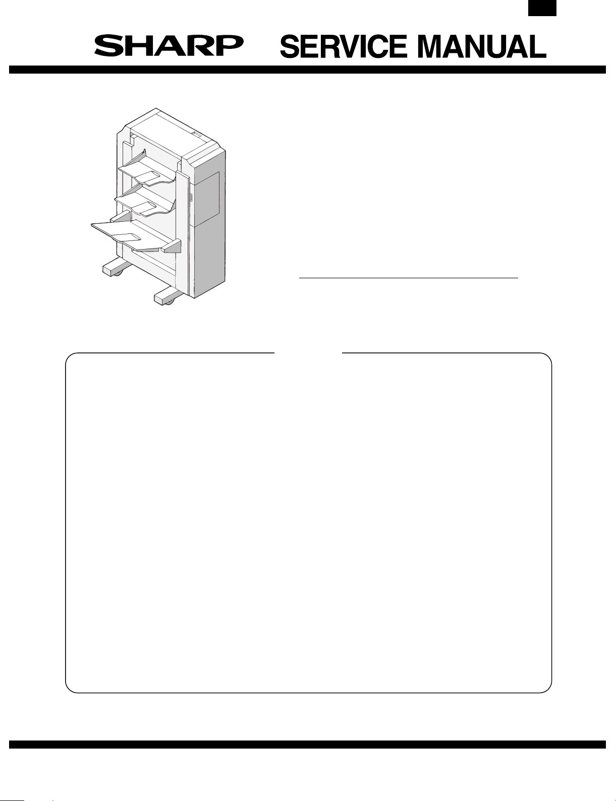
DIGITAL COPIER
OPTION FINISHER
MODEL AR-FN1N
AR-FN1N
CONTENTS
[Note]
• This Service Manual describes only the differences from AR-FN1. The items
which are not described in this Manual are common with the AR-FN1.
• The chapters marked with ∗ are partly modified from those of the AR-FN1.
Refer to the attached list of changes.
*[ 1 ] SPECIFICATIONS . . . . . . . . . . . . . . . . . . . . . . . . . . . . . . . . . . . . . . . . 1-1
*[ 2 ] UNPACKING AND INSTALLATION . . . . . . . . . . . . . . . . . . . . . . . . . . . 2-1
*[ 3 ] EXTERNAL VIEW AND INTERNAL STRUCTURE . . . . . . . . . . . . . . . 3-1
*[ 4 ] OPERATIONAL DESCRIPTIONS . . . . . . . . . . . . . . . . . . . . . . . . . . . . 4-1
*[ 5 ] DISASSEMBLY AND ASSEMBLY . . . . . . . . . . . . . . . . . . . . . . . . . . . . 5-1
*[ 6 ] ADJUSTMENTS . . . . . . . . . . . . . . . . . . . . . . . . . . . . . . . . . . . . . . . . . . 6-1
*[ 7 ] MAINTENANCE . . . . . . . . . . . . . . . . . . . . . . . . . . . . . . . . . . . . . . . . . . 7-1
*[ 8 ] TROUBLESHOOTING . . . . . . . . . . . . . . . . . . . . . . . . . . . . . . . . . . . . . 8-1
*[ 9 ] CIRCUIT DESCRIPTIONS . . . . . . . . . . . . . . . . . . . . . . . . . . . . . . . . . . 9-1
*[10] ELECTRICAL SECTION . . . . . . . . . . . . . . . . . . . . . . . . . . . . . . . . . . . 10-1
PARTS GUIDE
Parts marked with "!" is important for maintaining the safety of the set. Be sure to replace these parts with specified
ones for maintaining the safety and performance of the set.
This document has been published to be used
SHARP CORPORATION
for after sales service only.
The contents are subject to change without notice.
Page 2
AR-FN1N
List of changes from AR-FN1 to AR-FN1N
No.
Page Item Content Change
1 1-1 [1]-11 Power consumption
Max. 60W Changed to Max. 70W.
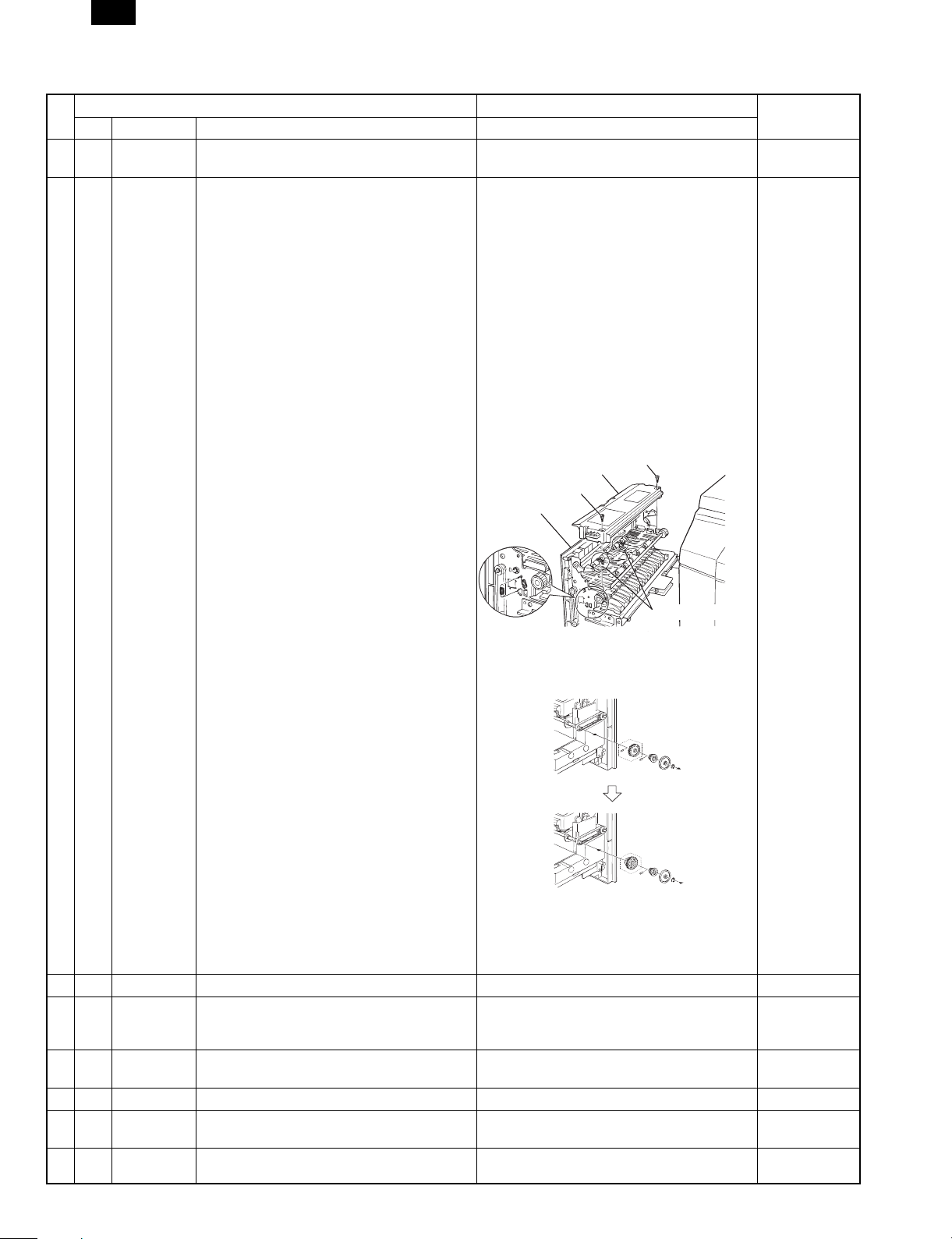
2 2-1 [2]-2 Installation 2. Add the following descriptions to the instal-
AR-FN1 AR-FN1N
lation procedure.
Before installing the AR-FN1:
* In the case of 2 trays
1. Pull out the paper exit unit from the copier
until it stops.
2. Remove the two screws which are fixing
the paper feed cover. Remove the paper
exit cover.
3. Remove the two transport springs attached
to the paper exitcover.
4. Hang the removed transport springs on the
paper exit unitfront frame (Fig. 1) to keep
there.
5. Return the paper exit cover to the original
position and fixit with two fixing screws.
Paper exit cover
Fixing screw
Fixing screw
Paper exit unit
[Fig.1]
Remark
Transport spring
6. Replace the connection gear at the rear of
the paper exit unitwith the gear packed
together with the unit as shown below.
Connection
gear
7. Insert the paper exit unit into the copier.
After completion of the above procedures,
perform installingprocedures according to
the installation manual.
3 2-4 [2]-2-14 Paper exit roller spring removal 14.Delete.
4 3-2 [3]-3 Clutch solenoid
5 3-4 [3]-5 Motor PWB unit
6 4-3 [4]-2-A Table No.(13): Signal name P12CL Signal name iP12CL is changed to T12CL.
7 4-6 [4]-2-E Elevator section
8 5-1 [5] Disassembly and assembly
llustration 12: T30RSL T30RSL is changed to T30RCL.
Table No. 12: T30RSL
Error print is corrected to
Table No.1: Main drive motor
Table No.(2): Name elevator drive unit Corrected to Elevator drive unit.
Table Item 2: Part name staple unit drive motor Corrected to Staple unit drive motor.
Main drive motor.
1/21/1999 – 1 –
Page 3

AR-FN1N
No.
Page Item Content Change
AR-FN1 AR-FN1N
9 6-1 [6] Adjustment
Table Item 1: Part name jogger F/R Delete "1. Jogger F/R" from the table.
[6]-1 Jogger F/R Delete "1 Jogger F/R."
10 6-7 [6]-11 Vertical transport roller unit
Set value Part code and price rank of the jig
are added to the set valuetable.
Set value
11 6-7 [6]-12 Paper entry port decurler unit
Nip amount adjustment
12 8-2 [8]-2-1 The finisher does not operate. (excluding the
case of jam)
Set value
Nip amount 0.5±0.1
External dimension of
shaft
Jigs Color jig R0.5
Part code: OEUKOG0602L//
Price rank: GN
Color jig F0.5
part code OEUKOG0603L//
Price rank: GN
21.6
Part code and price rank are added to the
table of nip amountadjustment.
Nip amount
(Reference)
External shaft
dimension
Inch series F/R
EX AB series F R
Japan F/R
Jig
0.5
0.8
±0.1
1.2
±0.1
±0.1
21.8 21.3 20.9 20.5
Part code: OEUKOG0601L//
Price rank: GN
Delete "upper transport open/close" in the
description. Refer tothe following.
Remark
1.6
±0.1
Check connection of
Is the
main PWB
DSW1.2.3PGOP
signal O.K. ?
YES
the copier, the harness
connection of the
NO
harness which is
connected to the top/
front/upper transport
open/close switch.
Replace if necessary.
13 9-5 [9]-4-D Extension I/O: M66500FP (IC3) expansion sig-
nal
Pin No.
Signal name
16
46 WLCL
48
64
STID2
STSL
T12CL
Specifications
Tray 3 speed reduction
clutch drive signal
(H: ON)
Staple tray paper
holding solenoid (H: ON)
Tray 1/2 speed
reduction clutch drive
signal (L: ON)
main PWB
DSW1.2.3PGOP
signal O.K. ?
Signal name:
Signal name:
Specification:
Signal name:
Specification:
Signal name:
Specification:
Is the
YES
Check connection of
the copier, the harness
NO
connection of the harness
which is connected to the
top/front switch. Replace if
necessary.
STID2 is changed to STID2/.
WLCL is changed to T3SLCL.
"Tray 3 sped change" is changed to
"Tray 3 speed reduction."
STSL is changed to T12CL.
"Staple tray paper holding solenoid
(ON at H)" is changed to "Tray 1/2
speed reduction clutch drive signal
signal (ON at H).
T12CL is changed to T30RCL1.
"Tray 1/2 speed reduction clutch
drive signal (ON at L)" is changed to
"Tray 3 paper exit roller clutch
(ON at L).
– 2 – 1/21/1999
Page 4

AR-FN1N
No.
Page Item Content Change
AR-FN1 AR-FN1N
14 10-1 [10]-1 Actual wiring diagram
Rear
4PIN
RD
RD
CN-C
1+24VIN1
2+24V12
BL
6+5V
CN-A
GY
5GND2
Rear
GY
1+24VINRD3GND1
FG
4PIN
Added.
GY
GY
GY
4GND1
GY
6
GY
FG
CN-C
RD
1+24VIN1
RD
2+24V12
GND2
GND316
CN-A
CN-B
CN-J
BL
CN-A
6+5V
5GND2
1+24VINRD3GND1
15 10-2 [10]-1 Main PWB 2/2
CN-J
GY
15 GND23
LB
14 T3UP4
BL
13 +5V5
6
CN-J
BL
1+5V
PK
2STND/
GY
3GND2
CN-J
GY
15 GND23
LB
14 T3UP4
BL
13 +5V5
6
PPSL/
2
1+24V
1
2
1
2
2
PPSL
CN-J
BL
1+5V
PK
2STND/
GY
3GND2
Added.
16 10-3 [10]-2 Main PWB
2-7C
RMA
2-7C
RMA/
2-7C
RMB
2-7C
RMB/
2-7B
PMA
2-7B
PMA/
2-7B
PMB
2-7B
PMB/
R201 10K
R136 10K
R135 10K
2-7A
STUMA
2-7A
STUMA/
2-7A
STUMB
2-7A
STUMB/
2-5C
OFMA
2-5C
OFMB
1-4A
PPSL
VCCVCC
RMA
RMA/
RMB
RMB/
PMA
PMA/
PMB
PMB/
RESO/
GND
F-RXDF-RXD
N.C
F-TXD
N.C
F-DSRF-DSR
F-DTR
F-DTR
STUMA
STUMA/
STUMB
STUMB/
GND
GND
OFMA
OFMB
STGSL
(YB2SL)
1
VCC
2
TIOCA3/TP8/PB0
3
TIOCB3/TP9/PB1
4
TIOCA4/TP10/PB2
5
TIOCB4/TP11/PB3
6
TOCXA4/TP12/PB4
7
TOCXB4/TP13/PB5
8
%%oDREQ0%%o/TP14/PB6
9
%%oADTRG%%o/%%oDREQ1%%o
10
%%oRESO%%o
11
VSS
12
TXD0/P90
13
TXD1/P91
14
RXD0/P92
15
RXD1/P93
16
%%oIRQ4%%o/SCK0/P94
17
%%oIRQ5%%o/SCK1/P95
18
D0/P40
19
D1/P41
20
D2/P42
21
D3/P43
22
VSS
23
D4/P44
24
D5/P45
25
D6/P46
26
D7/P47
IC02
2-7A
2-7A
2-7A
2-7A
2-5C
2-5C
1-4A
2-7C
2-7C
2-7C
2-7C
2-7B
2-7B
2-7B
2-7B
R201 10K
RMA
RMA/
RMB
RMB/
PMA
PMA/
PMB
PMB/
R136 10K
R135 10K
STUMA
STUMA/
STUMB
STUMB/
OFMA
OFMB
PPSL
VCCVCC
RMA
RMA/
RMB
RMB/
PMA
PMA/
PMB
PMB/
RESO/
GND
F-RXDF-RXD
N.C
F-TXD
N.C
F-DSRF-DSR
F-DTR
F-DTR
STUMA
STUMA/
STUMB
STUMB/
GND
GND
OFMA
OFMB
STSL
(STSL)
1
VCC
2
TIOCA3/TP8/PB0
3
TIOCB3/TP9/PB1
4
TIOCA4/TP10/PB2
5
TIOCB4/TP11/PB3
6
TOCXA4/TP12/PB4
7
TOCXB4/TP13/PB5
8
%%oDREQ0%%o/TP14/PB6
9
%%oADTRG%%o/%%oDREQ1%%o
10
%%oRESO%%o
11
VSS
12
TXD0/P90
13
TXD1/P91
14
RXD0/P92
15
RXD1/P93
16
%%oIRQ4%%o/SCK0/P94
17
%%oIRQ5%%o/SCK1/P95
18
D0/P40
19
D1/P41
20
D2/P42
21
D3/P43
22
VSS
23
D4/P44
24
D5/P45
25
D6/P46
26
D7/P47
IC02
Remark
STGSSS+ (YB2SL) is
changed to STSL.
17 10-5
[10]-2 Main PWB circuit diagram The following figure is added to Main PWB cir-
10-6
cuit diagram D-5 Added.
Added.
+
C03
47U/35V
STUMA
CNH-05
STUMA/
STUMA/
CNH-06
STUMBSTUMB
CNH-07
STUMB/
STUMB/
CNH-08
18 10-8 [10]-2 Main PWB connector signal table D-4 Connector signal table D-4
T3SLCL/ is changed to T3SLCL.
(Refer to the table below.)
CNL (B14B-PHDSS)
SIGNALNO
+24V
01
PPSL/
02
+24V
03
T3SLCL/
04
COM705
PPSL
T3SLCL/
CNL (B14B-PHDSS)
+24V
01
PPSL/
02
03
+24V
04
T3SLCL/
COM705
CNJ-13
+5V
0.1uF
+24V
CNJ-15
SIGNALNO
C75
0.1uF
PPSL
T3SLCL
CNH-29
1-4B
STMB
1-4B
STMA
1/21/1999 – 3 –
Page 5

AR-FN1N
q
COPYRIGHT © 1999 BY SHARP CORPORATION
All rights reserved.
Printed in Japan.
No part of this publication may be reproduced,
stored in a retrieval system, or transmitted,
in any form or by any means,
electronic, mechanical, photocopying, recording, or otherwise,
without prior written permission of the publisher.
SHARP CORPORATION
Printing & Reprographic Systems Group
Quality & Reliability Control Center
Yamatokoriyama, Nara 639-1186, Japan
1999 January Printed in Japan
 Loading...