

Page 1
SERVICE MANUAL
CODE: 00ZARF13//A1E
DIGITAL FULL COLOR COPIER/PRINTER/
MULTIFUNCTIONAL SYSTEM OPTION
SADDLE STITCH FINISHER
AR-F13
MODEL
CONTENTS
[1] INTRODUCTION . . . . . . . . . . . . . . . . . . . . . . . . . . . . . . . . . . . . . . 1-1
[2] EXTERNAL VIEWS AND INTERNAL STRUCTURES . . . . . . . . . . 2-1
[3] UNPACKING AND INSTALLATION . . . . . . . . . . . . . . . . . . . . . . . . 3-1
[4] OPERATIONAL DESCRIPTION. . . . . . . . . . . . . . . . . . . . . . . . . . . 4-1
[5] DISASSEMBLY AND ASSEMBLY . . . . . . . . . . . . . . . . . . . . . . . . . 5-1
[6] MAINTENANCE . . . . . . . . . . . . . . . . . . . . . . . . . . . . . . . . . . . . . . . 6-1
[7] MACHINE OPERATION. . . . . . . . . . . . . . . . . . . . . . . . . . . . . . . . . 7-1
[8] ADJUSTMENTS . . . . . . . . . . . . . . . . . . . . . . . . . . . . . . . . . . . . . . . 8-1
[9] TROUBLESHOOTING . . . . . . . . . . . . . . . . . . . . . . . . . . . . . . . . . . 9-1
AR-PN1
[10] SIMULATIONS . . . . . . . . . . . . . . . . . . . . . . . . . . . . . . . . . . . . . . . 10-1
[11] ELECTRICAL SECTION. . . . . . . . . . . . . . . . . . . . . . . . . . . . . . . . 11-1
PARTS GUIDE
Parts marked with “ ” are important for maintaining the safety of the set. Be sure to replace these parts with
specified ones for maintaining the safety and performance of the set.
This document has been published to be used
SHARP CORPORATION
for after sales service only.
The contents are subject to change without notice.
Page 2

[1] INTRODUCTION
1. Product outline
This unit is installed to the following machines to perform the after-process of output paper from a printer, a copier, or a fax machine.
1) Employment of the through-type stapler
Employment of the through-type stapler allows to make saddle
stitch by one stapler.
2) 3 kinds of auto staple functions
There are 3 staple positions available. (One position in the front,
one position at the back, 2 positions at the center)
3) Saddle stitch function
Up to 10 sheets of paper can be stapled at the center and folded
into two and discharged.
4) Punch function (Option)
By installation of a puncher unit, paper can be punched to make
holes for a binder. (Applicable for 64 - 128g/m². OHP films cannot
be used.)
Applicable models AR-C260/C260M
2. Configuration
1. Before installation of this unit, the large-capacity paper feed tray
(AR-LC5) or the 1-stage paper feed desk (AR-D17) or the 3-stage
paper feed desk (AR-D18) or the duplex 2-stage duplex paper feed
desk (AR-D19) must be installed in advance.
2. When installing this unit, the duplex pass and reverse unit (ARPB1) must be installed together.
3. This unit cannot be installed with the sorter (AR-S11) together.
3. Specifications
Model AR-F13
Type 2-bin type saddle stitch finisher
Mount type Floor type
Conditions The paper feed desk and the reverse bypass
Reverse section None (Reverse bypass module takes this
Transport speed Color: 25 sheets/min.; B/W: 32 sheets/min.
Transport alignment Center alignment
Tray type Offset tray Book tray for saddle
Capacity of paper
exit and load
Paper exit direction Face-up/face-down Face-down
module must be installed in advance.
section.)
(LT), 33 sheets/min. (A4)
Upper tray Lower tray
stitch
1,000 sheets:
A4/8.5" x 11"/B5:
2
80 g/m
(Capacity varies
depending on the user
circumstance or paper
condition.)
500 sheets:
Larger size than A4/
8.5" x 11", invoice, A5,
A4R
10 sheets x 10 sets
2
(80 g/m
)
Paper size to be
discharged
Paper weight to be
discharged
Remaining paper
detection
Discharged paper
full detection
Offset function Provided (25mm) N/A
Paper size which
can be stapled
Quantity of paper to
be stapled (max.)
Stapling One at the back,
Stacking Horizontal dislocation: Within 20 mm
Alignment (max.
misalignment)
Staple standard Face-down standard Face-down standard
Staple supply Refill type
Staple detection Staple empty detection: Provided
Power consumption 45W or below
Power supply Supplied from the main unit (paper feed desk)
External dimensions
(W x D x H)
Weight Approx. 39 kg
Communication type Serial communication
Option detection Automatic detection
Face-up
Any paper available.
(Offset is not available
for A3 Wide (12x18),
OHP, postcard,
envelope, A5R and
special.)
Face-down
A3 wide (12” x 18”) A3,
B4, A4, A4R, B5, B5R,
8K, 16K, 16KR
11" x 17", 8.5" x 14",
8.5" x 13", 8.5" x 11",
8.5" x 11"R, 5.5" x 8.5",
7.25 x 10.5R
(Offset is not available
for A3 Wide (12 x 18).)
Face-up
64 to 300 g/m
17 to 80 lbs.
Face-down
64 to 200 g/m
17 to 55 lbs.
Provided Provided
Provided Provided
wo positions:
t
A3, B4, A4, B5,
11
"
x 17", 8.5" x 11",
8K, 16K, Legal,
Letter-R, A4R
one at the back:
A3, B4, A4, A4R,
B5, 11
8
.5" x 14",
"
x 13", 8.5" x 11",
8.5
"
x 11"R, 8K, 16K,
8.5
16KR
30 sheets
(A4/LT: 80 g/m
Target: 50 sheets
(A4: MI paper, M
paper)
two positions (one in
the front)
Vertical dislocation: Within 50 mm
(at offset-staple)
Alignment does not matter for non-offset and
750 sheets or above.
Within 2.5 mm (Nominal)
(at offset-staple)
Cartridge empty detection: Provided
Staple jam detection: Provided
(DC 24V, 2.7A) DC 5V
728 x 603 x 1,000 (mm)
"
x 17
2
/
2
/
",
2
A3, B4, A4R, 11"x17",
8.5"x11"R, 8.5"x14
64 to 105 g/m
17 to 28 lbs.
A3, B4, A4R, 11" x 17",
8.5" x 11"R, 8.5" x 14"
10 sheets
)
(A4/LT: 80 g/m2)
Center stapling, center
folding
2
/
AR-F13 INTRODUCTION 1-1
Page 3
[2] EXTERNAL VIEWS AND
INTERNAL STRUCTURES
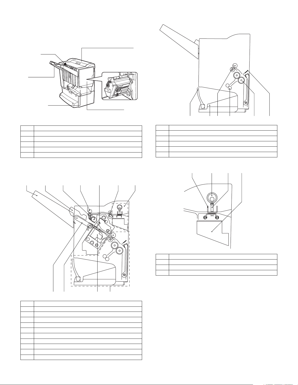
1. External view
[1]
[3]
[6]
B. Saddle section
[2]
[5]
[1] Stapler compiler
[2] Top cover
[3] Stapler section
[4] Front cover
[5] Saddle stitch tray
[6] Offset tray
2. Internal structure
A. Finisher section
[1]
[2]
[3] [7][5][4] [6]
[4]
[1]
[1] Book making stopper
[2] Book making tray
[3] Bundle transport roller
[4] Book making exit roller
[5] Paper folding roller
[6] Paper pushing plate
[3]
[4][2]
C. Puncher section (Option: AR-PN11)
[3][1]
[2]
[4]
[5]
[6]
[9]
[8]
[1] Paper exit tray
[2] Alignment plate (Front, back)
[3] Paddle
[4] Paper exit roller
[5] Process tray stopper
[6] Transport roller
[7] Puncher section (Option)
[8] Paper exit belt
[9] Bundle exit roller
[10] Stapler
[11] Saddle section
[1] Dice
[2] Cam
[3] Punch
[4] Punch dust box
[10]
[11]
AR-F13 EXTERNAL VIEWS AND INTERNAL STRUCTURES 2-1
Page 4

3. Finisher and saddle section
A. Sensor
SSS
LLLS
FJHPS
RJHPS
SLS
LE
PHPS
FRHPS
FPS
FES
ULS
ARHPS
FHPS
PI18
PI19
PI20
PI21
FDSW
BES
FDS
TCS
AS
OBHPS
O
Code Name Active condition Remark
SPS Self prime sensor Cartridge staple
detected : "L"
SS Staple sensor Stapler cartridge
detected : "L"
FDS Front door sensor Front cover open : "H"
FE
TCS Upper cover sensor Upper cover open : "H"
FDSW Front door switch Front door closed : "H"
JS Joint switch Printer connected : "H"
SSS Stapler safety switch Oscillation guide closed :
"H"
B. Motor and PWB
JS
FPM
FFM
FSM
ES
FFC
Code Name Active condition Remark
ES Entry sensor Paper detected : "H"
PHPS Paddle home position
Paddle HP : "H"
sensor
ARHPS Bundle roller home
Oscillation guide HP : "H"
position sensor
FJHPS Alignment home
position sensor (front)
RJHPS Alignment home
position sensor (rear)
Alignment tray (F) HP :
"H"
Alignment tray (R) HP :
"H"
AS Alignment tray sensor Paper detected : "H"
OBHPS Exit belt home
Paper exit belt HP : "H"
position sensor
BES Tray paper sensor Tray paper detected : "H"
SLS Paper level sensor Paper detected : "H"
FPS Bookbinding position
Paper detected : "L"
sensor
FHPS Bookbinding home
position sensor
FRHPS Bookbinding roller HP
sensor
FES Bookbinding paper
Folding operation
HP : "L"
Bundle transport roller
HP : "H"
Paper detected : "H"
sensor
FE Bookbinding clock
sensor
ULS Lift upper sensor Tray upper limit detected :
"H"
LLLS Lift lower sensor Tray lower limit detected :
"H"
LE Lift lock sensor
SHPS Slide home position
Stapler HP : "H"
sensor
STHPS Stapler home position
Stapler stapling HP : "L"
sensor
FAM
FRJM
FFJM
FLM
FFSM
[1]
Code Name Active condition Remark
FFM Transport motor Paper transport
FPM Paddle motor Oscillation guide drive,
paper exit to offset tray
FAM Bundle exit motor Paper exit operation
FFJM Alignment motor (front) Alignment plate (F) drive
FRJM Alignment motor (rear) Alignment plate (R) drive
FLM Shift motor Paper exit tray up/down
FFSM Stapler/Fold motor Stapling/paper folding
FSM Slide motor Staple unit sliding
AR-F13 EXTERNAL VIEWS AND INTERNAL STRUCTURES 2-2
Page 5
4. Puncher section (AR-PN1)
A. Sensor
C. PWB
PE
Punch home position
PSHPS
Code Name Active condition Remark
Punch home position
sensor
PSHPS Punch side home
position
PE Punch dust sensor In the
Punch HP detected:"L" In the
Punch slide unit HP
detected:"H"
punch unit
In the
punch unit
punch unit
B. Motor
[1]
[4]
[2]
[3]
[5]
Code Name
[1] Punch driver PWB
[2] Side resist photo sensor PWB
[3] Side resist LED PWB
[4] Dust full photo sensor PWB
[5] Dust full LED PWB
FPNM
FPSM
Code Name Active condition Remark
FPNM Punch motor Punch drive
FPSM Punch side motor Punch slide unit
transverse move
AR-F13 EXTERNAL VIEWS AND INTERNAL STRUCTURES 2-3
Page 6

[3] UNPACKING AND
INSTALLATION
1. AR-F13
<Before installation>
• Start installation after checking that the DATA indicator on the operation panel is neither lit nor blinking.
• For installation of AR-F13, an optional stand (AR-D17, AR-D18 or
AR-D19) and a duplex bypass/inverter unit (AR-RB1) must have
been installed.
• Ensure that the connecting plate on the front of the optional stand
and the two supplied connection plates are securely attached.
Parts included
Exit tray:
1 pc.
Staple unit:
1 pc.
Lock plate:
1 pc.
Front cover:
1 pc.
Screw A (M4 x 6):
4 pcs.
Screw B (M4 x 10):
2 pcs.
Screw C (M4 x 18):
5 pcs.
Grounding plate:
1 pcs.
Connecting plate:
1 pc.
Screw E (M4 x 7):
4 pcs.
Staple cartridge: 1 pc.
Staple position label:
1 sheet
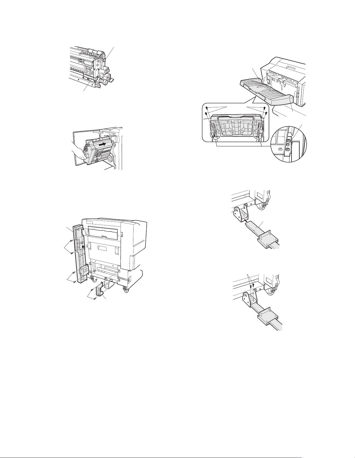
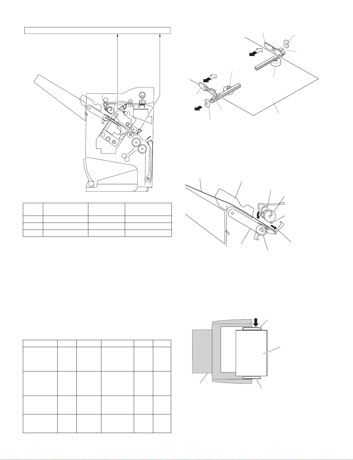
2) Remove the actuator.
<1> While holding the base of the exit actuator of the duplex
bypass/inverter unit with one hand, pull the end of the exit
actuator with the other hand to remove the actuator.
<2> If the exit tray is installed to the duplex bypass/inverter unit,
remove it.
Actuator
3) Attach the lock plate and the grounding plate.
<1> Remove the screw from the rear side of the duplex bypass/
inverter unit.
<2> Put the lock plate to the duplex bypass/inverter unit and
attach it with screw C on the front side and with screw D on
the rear side.
<3> Remove the exterior securing screw, put the two grounding
plates to the main unit, and secure them with screws C (two
for each).
∗ At this time, attach the front grounding plate so that marking F is
positioned up.
Screw
Screw D
(M4 x 18 with rosette):
1 pc.
punch position label:
1 sheet
1) Turn off the main switch.
<1> Turn the main switch located at the left side of the main unit
to the "OFF" position.
<2> Remove the power plug from the outlet.
"OFF"
<1>
Screw D
Lock plate
<2>
Screw C
Exterior
securing screw
Screws C
<3>
Grounding plate
AR-F13 UNPACKING AND INSTALLATION 3-1
Page 7
4) Attach the staple unit to the finisher.
Screws A
<1> Open the front cover of the saddle finisher.
<2> Remove the two pieces of packing tape from the staple unit.
Packing tape
Packing tape
6) Attach the exit tray to the saddle finisher.
<1> Put the two pawls of the exit tray onto the saddle finisher.
<2> Secure the exit tray with four screws E.
At this time, ensure that the positioning dowel is securely
inserted.
Pawl
<3> Hold the handle and the bottom side of the staple unit, and
insert the unit into the saddle finisher.
<4> Close the front cover of the saddle finisher.
5) Attach the front cover to the saddle finisher.
<1> Put the plate R to the saddle finisher so that marking R is
positioned up and then secure the plate with two screws A.
<2> Put the front cover to the saddle finisher as shown in the illus-
tration and secure the cover with two screws B at the upper
part and two screws A at the lower part (four screws in total).
Front cover
Screws B
Screws E
Pawl
Positioning dowel
7) Attach the connecting plate to the saddle finisher.
<1> Insert the connecting plate into the sheet metal at the lower
part of the saddle finisher.
Connecting plate
<2> Secure the connecting plate to the saddle finisher with two
screws A.
Screws A
Screws A
Plate R
AR-F13 UNPACKING AND INSTALLATION 3-2
Page 8
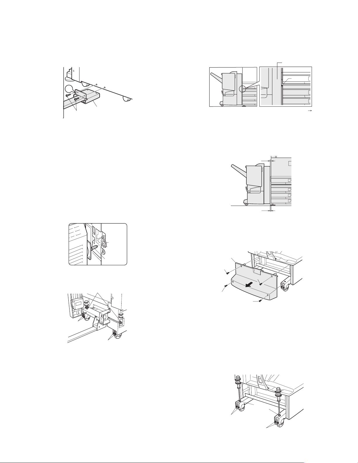
8) Connect the saddle finisher to the main unit.
Clearance A
Clearance B
Adjusting part
securing screws
Adjusting part
securing screws
Front side
Rear side
<1> Move the saddle finisher toward the left (exit area) of the main
unit.
<2> Position the connecting plate that has been attached to the
saddle finisher to the two holes at the lower left of the
optional stand, and secure it with two screws C.
At this time, attach the rear screw to the hole with marking C.
Optional stand
<4> Turn the front height adjusting handle so that the height of
the top of the rib on the front cover matches with the height of
the top of the stand.
<5> Tighten the adjusting part securing screws (two for each of
front and rear).
<6> Carry out work B. (next page)
Front cover
Main unit
Rib
C
Screws C
9) Adjust the height of the saddle finisher.
<1> Move the saddle finisher close to the main unit.
<2> Ensure that the guide pin of the lock plate that has been
attached to the duplex bypass/inverter unit is inserted
smoothly into the connecting hole of the saddle finisher.
∗ If the guide pin should not inserted smoothly, adjust it using the pro-
cedure described below.
A. If the connecting hole of the saddle finisher is deviated from the
guide pin of the lock plate:
<1> Loosen the two adjusting part securing screws at the rear of
saddle finisher stand section.
<2> Turn the rear height adjusting handle so that the height of the
guide pin matches with the height of the center of the connecting hole.
<3> Loosen the two adjusting part securing screws at the front of
the saddle finisher stand section.
Connecting plate
Adjusting
hole
Guide pin
Stand
Continued to the next page
B: If the connecting hole of the saddle finisher matches with the guide
pin of the lock plate:
<1> Push the saddle finisher toward the main unit.
<2> Check the clearance between the saddle finisher and the
main unit at the upper and lower parts.
• If clearance A is not equal to clearance B:
<1> Remove the four screws that secure the cover of the saddle
finisher stand and remove the cover.
Cover
Screw
Screw
Front side
Adjusting
part securing
screws
Height adjusting handles
Adjusting part securing screws
Rear side
Screw
Screw
<2> Loosen the adjusting part securing screws (two for each of
front and rear).
<3> Turn the height adjusting screws (one for each of front and
rear) respectively so that clearance A becomes equal to
clearance B.
<4> Check that clearance A and clearance B are uniform both at
the front and at the rear.
<5> Tighten the adjusting part securing screws (two for each of
front and rear).
Height adjusting
screws
AR-F13 UNPACKING AND INSTALLATION 3-3
Page 9

<6> Reattach the removed cover so that the four securing bosses
of the cover are inserted into the four positioning holes and
then tighten the four screws in the order of <1> and <2>
shown in the illustration to secure the cover.
Cover
Screw
<2> Push the staple cartridge securely into the staple section until
it clicks.
<2>
Screw
Screw
<1>
Screw
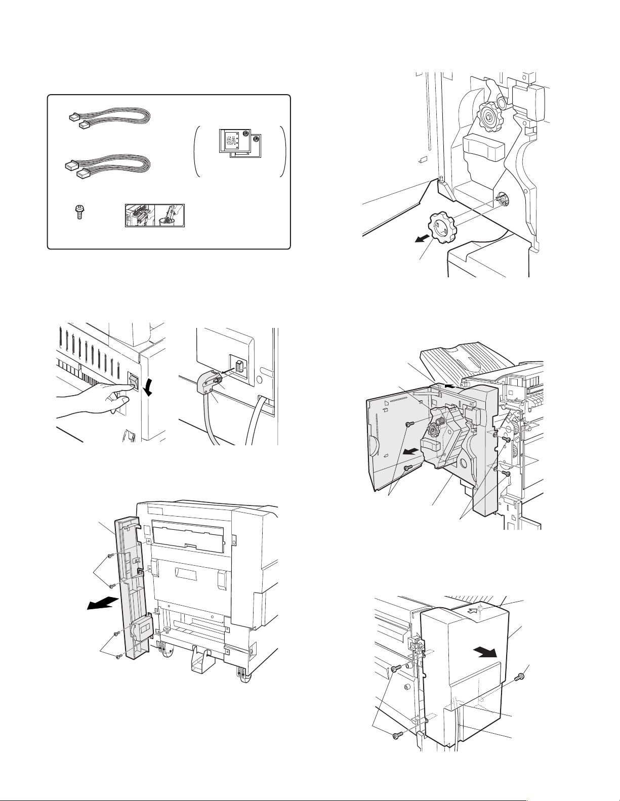
10) Connect the connector of the saddle finisher.
<1> Remove the screw that secures the power supply cover at
the rear face of the stand and remove the power supply
cover.
<2> Cut out the portion of the power supply cover shown in the
illustration.
<3> Secure the power supply cover to the rear cabinet.
Cut-out portion
Screw
Power supply cover
<4> Connect the connector for connecting the saddle finisher to
the connector on the stand and secure it with the screw on
the connector.
[Note]
Check that the right
and left of the staple
cartridge are not
loose.
13) Attach the staple unit to the finisher.
Insert the staple section and close the front cover of the finisher.
14) Paste the staple position label.
Open the front cover and paste staple position label A to the posi-
tion shown in the illustration.
Screw
Connector
If another peripheral device must be installed, carry out the following
steps at the end of the installation work.
11) Move the staple unit of the saddle finisher to
the cartridge insertion position.
<1> Insert the power plug of the main unit to the outlet and turn
on the main switch.
<2> Wait for some time until the initial operation of the saddle fin-
isher is complete.
12) Set the staple cartridge to the staple unit.
<1> Open the front cover of the saddle finisher and pull out the
staple unit.
For Scanner
X
Y
If the B/W scanner module/DSPF is attached, paste staple position
label B to the position on the B/W scanner module/DSPF shown in
the illustration.
For RADF
Y
X
AR-F13 UNPACKING AND INSTALLATION 3-4
Page 10
2. AR-PN1
<Before installation>
For installation of AR-PN1A/PN1B/PN1C/PN1D, a saddle stitch
finisher (AR-FN13) must have been installed.
Parts included
Harness A (purple): 1 pc.
Hole punch position label*:
2 sheets
Harness B (orange): 1 pc.
Screw
(M4 x 6 with rosette)
: 1 pc.
Dust box label:
1 sheet
* Will not be used.
Use the hole punch
position labels packed
in AR-F13.
3) Remove the front cabinet and the rear cabinet from the finisher.
<1> Open the front door of the finisher and remove the jam han-
dling dial.
1) Turn off the main switch of the main unit of the printer.
<1> Turn the main switch located on the front side of the main
unit to the "OFF" position.
<2> Then remove the power plug of the main unit from the outlet.
<3> Loosen the screw and remove the connector of the finisher.
Screw
Connector
2) Remove the front cover from the right front of the finisher.
Remove the screws A and B (two for each) that secure the finisher
front cover and remove the front cover.
Front cover
Screws B
Jam handling dial
<2> Remove the four front cabinet securing screws, pull out the
staple unit until it stops, then remove the pawl of the front
cabinet in the direction indicated by the arrow and remove
the front cabinet.
Pawl
Staple unit
Screws
Front cabinet
Screws
<3> Remove the three rear cabinet securing screws, remove the
pawl in the direction indicated by the arrow, and remove the
rear cabinet.
At this time, remove the relay harness through the opening of
the rear cabinet.
Pawl
Screws A
Screw
AR-F13 UNPACKING AND INSTALLATION 3-5
Rear
cabinet
Screw
Opening for
relay harness
Relay harness
Page 11

4) Remove the top cover.
<1> Remove the four top cover securing screws and remove the
top cover.
Screw
Top cover
<2> Remove the four pawls from the top cover and separate the
cover into the upper and lower portions. Reuse the upper
portion.
Pawl
Top cover
Pawl
<2> Remove the two paper-in PG securing screws.
<3> Remove the upper bosses of the paper-in PG.
<4> Remove the lower bosses of the paper-in PG with a minus
screwdriver etc.
5) Remove the paper-in PG of the punch unit.
<1> Remove the dust box.
1
<5> Remove the paper-in PG.
<6> Reattach the dust box.
AR-F13 UNPACKING AND INSTALLATION 3-6
Page 12

6) Attach the punch module.
Screw
Relay harness
Opening for
relay harness
Screws
Rear cabinet
<1> Insert the two bosses of the punch unit into the boss holes of
the finisher and fix the punch module using three screws.
Note: For the screws, use a supplied screw and the two screws
that have been removed in step 4).
Boss hole
Boss hole
Boss
Screw
Punch module
Boss
8) Reattach the covers that have been removed.
<1> Hang the two pawls of the top cover and secure them using
the two screws.
Screw ScrewTop cover
Pawl
Screw
Screw (with rosette)
(supplied with this unit)
7) Connect the harness of the punch module to the PWB of the finisher.
Remove the clamps that fix the harness, handle the wiring of harness A (purple) and harness B (orange), and fix them with the
clamps.
Harness B (orange)
Harness A (purple)
Clamps
<2> Pass the relay harness to the rear cabinet and secure the
rear cabinet using the three screws.
<3> Remove the lock release lever that has been attached to the
front cabinet.
Reattach the front cabinet to its original position, push in the
staple unit, and attach it using the two screws.
Insert the protrusion (B) of the lock release lever that has
been removed before to the hole (C) of the latch arm.
After attaching it, move the lever to check that it moves
smoothly.
If the lever does not move smoothly, remove the lock release
lever by releasing the pawl at the lower part of the lock
release lever using a flat-blade screwdriver or the like and
then insert it again.
Harness B (orange)
Clamps
Harness A (purple)
Staple unit
Screws
Front cabinet
AR-F13 UNPACKING AND INSTALLATION 3-7
Latch arm
Pawl (D)
Lock release
lever (A)
Projection (B)
Page 13

<4> Reattach the jam handling dial and close the front cover.
9) Reattach the front cover to the right front of the finisher.
<1> Attach the front cover using the screws A and B (two for
each).
Front cover
11) Connect the connector to the stand/paper drawer.
Connect the connector of the relay harness of the finisher to the
stand/paper drawer and tighten the screws of the connector.
Screws
Connector
12) Paste the label.
Paste the label to the position shown in the illustration.
Screws B
Screws A
10) Paste the dust box label to the top cover.
<1> Paste the supplied dust box label to the location indicated in
the illustration.
For RADF
For Scanner
Punch label
STP label
X
Y
Y
On completion of the installation of the AR-F13 finisher, please change
the default output tray of the machine to the top tray of the finisher.
AR-F13 UNPACKING AND INSTALLATION 3-8
Punch label
STP label
X
Page 14

[4] OPERATIONAL DESCRIPTION
1. Basic Operations
A. Specifications
The finisher serves to deliver sheets coming from its host machine. The
mode of delivery may be non-sort stack, job offset*, or staple delivery.
The saddle unit built into the finisher is used to fold a stack of sheets
coming from the finisher unit in half for delivery.
All these operations are controlled by various commands sent by the
host machine in addition to the commands from the finisher controller
PCB.
The puncher unit (option) is designed for installation to the pickup
assembly of the finisher, and is used to punch holes in sheets coming
from the host machine.
The above operations are controlled with various commands from the
finisher controller PCB as well as the commands from the punch
controller PCB.
Puncher unit drive
system (puncher unit;
option)
Alignment drive system
Stapler drive system
Delivery drive system
Control system
Feed drive system
Tray drive system
Saddle unit
drive system
B. Outline of the Electrical Circuitry
The sequence of finisher operations is controlled by the finisher
controller PCB. The finisher controller PCB is a 16-bit microprocessor
(CPU), and is also used for combination with the host machine (serial).
The finisher controller PCB drive motors and other loads in response to
the various commands from the host machine. It also communicates
such data as on the states of various sensors and switches to the host
machine by way of the serial communication line.
The ICs mounted to the finisher controller PCB have the following
functions:
•IC13 (CPU)
Controls sequence of operations.
•IC12 (EEP-ROM)
Backs up adjustment settings.
•IC6 (EP-ROM)
Stores sequence programs.
•IC11 (communication IC)
Communicates with the host machine.
•IC1 (regulator IC)
Generates 5 V.
F02-102-01 shows the flow of signals between finisher and options
controller:
Finisher unit
Host machine DC
Finisher
controller
PCB
IC13
CPU
IC12
EEP-ROM
IC11
Communica-
tion IC
IC6
EP-ROM
IC1
Regulator IC
Motor
Clutch
Switch
Sensor
Puncher unit (option)
Punch controller
PCB
Motor
controller PCB
CPU
Sensor
NOTE:The position of delivery is shifted to the front/rear for each stack to
assist sorting.
AR-F13 OPERATIONAL DESCRIPTION 4-1
Page 15

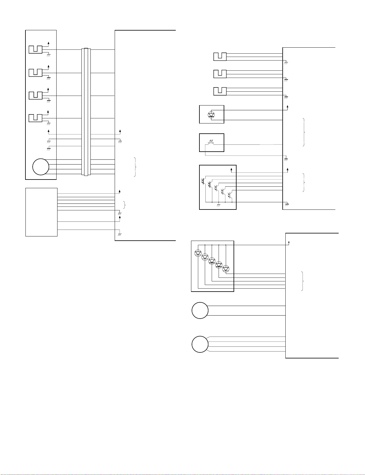
C. Inputs to and Outputs from the Finisher Controller
PCB
•Inputs to the Finisher Controller PCB (1/2)
CN16-10
CN9-1
CN9-7
CN4
CN5-13
CN5-1
CN5-10
CN16-1
-12
-11
-15
-14
-12
-11
Finisher controller PCB
+5 V
ENT_S
+5 V
-3
PDL_HP
-2
+5 V
-9
BDL_ROL_HP
-8
+5 V
-3
F JOG_HP
-2
+5 V
R JOG_HP
+5 V
-3
ADJ_TRAY_S
-2
-4
+5 V
-6
EJCT_BLT_HP
-5
-7
+5 V
-9
TRY_EMPS
-8
+5 V
LVL_S
+5 V
-2
BIND_P
-3
BIND_L
When the sensor
detects paper, ‘1’ .
When the paddle is at
home position, ‘1’.
When the swing guide
is at home position, ‘1’.
When the aligning
plate (front) is at
home position, ‘1’.
When the aligning
plate (rear) is at
home position, ‘1’.
When the sensor
detects paper, ‘1’.
When the delivery belt
is at home position, ‘1’.
When paper is present
on the tray, ‘1’.
When the paper
surface is detected,
‘1’.
When paper is
detected, ‘0’.
When LED is lit, ‘1’.
Inlet sensor
Paddle home
position sensor
Swing guide
home position
sensor
Aligning plate
home position
sensor (front)
Aligning plate
home position
sensor (rear)
Processing
tray sensor
Delivery belt
home position
sensor
Tray paper sensor
Paper surface
sensor
Folding position
sensor
ES
PHPS
ARHPS
FJHPS
RJHPS
AS
OBHPS
BES
SLS
FPS
CN44-3
CN51-1
CN55-3
CN23-3
CN36-3
CN30-3
CN31-3
CN32-3
CN35-3
CN39-3
CN43-1
-1
-2
-3
-2
CN54-1
-1
-2
-1
-2
-1
-2
CN29-1
-1
-2
-1
-2
-1
-2
CN34-1
-1
-2
CN38-1
-2
-1
CN42-3
CN53-3
CN28-9
CN33-3
CN37-9
-1
-2
-1
-2
-7
-8
-6
-4
-5
-3
-1
-2
-1
-2
-8
-7
-3
-2
-3
-2
-3
-2
-4
-6
-5
-7
-9
-8
-3
-2
-2
-3
•Outputs from the Finisher Controller PCB (1/2)
Binding clutch
FFC
Feed motor
FFM
Paddle motor
FPM
Delivery motor
FAM
Alignment motor
(front)
FFJM
Alignment motor
(rear)
FRJM
CN63-1
CN65-1
-1
-2
-2
-1
CN72
-6
-1
-5
-2
-4
-3
-3
-4
CN56
-2
-5
-1
-6
-6
-1
-5
-2
-4
-3
-3
-4
CN57
-2
-5
-1
-6
-6
-1
-5
-2
-4
-3
-3
-4
CN59
-2
-5
-1
-6
CN62-5
-2
-3
-4
-5
CN64-5
-2
-3
-4
-5
CN18-1
-2
B_CLU
CN10-1
-2
-3
FEEDMTR_A
-4
FEEDMTR_*A
-5
FEEDMTR_B
-6
FEEDMTR_*B
CN10-7
-8
-9
PDLMTR_A
-10
PDLMTR_*A
-11
PDLMTR_B
-12
PDLMTR_*B
CN13-1
-2
-3
EJCTMTR_A
-4
EJCTMTR_*A
-5
EJCTMTR_B
-6
EJCTMTR_*B
CN3-1
-4
-3
-2
-1
-2
FJOGMTR_A
-3
FJOGMTR_*A
-4
FJOGMTR_B
-5
FJOGMTR_*B
CN3-6
-4
-3
-2
-1
-7
RJOGMTR_A
-8
RJOGMTR_*A
-9
RJOGMTR_B
-10
RJOGMTR_*B
Finisher controller PCB
+24 V
When the drive is transmitted,
‘1’.
+24 V
Switches between ‘1’ and
‘0’ according to the
direction of motor rotation.
+24 V
Switches between ‘1’ and
‘0’ according to the
direction of motor rotation.
+24 V
Switches between ‘1’ and
‘0’ according to the
direction of motor rotation.
+24 V
Switches between ‘1’ and
‘0’ according to the
direction of motor rotation.
+24 V
Switches between ‘1’ and
‘0’ according to the
direction of motor rotation.
•Inputs to the Finisher Controller PCB (2/2)
FHPS
Folding home
position sensor
Stack feed roller
(upper) home
position sensor
Bind tray sensor
Staple/fold motor
clock sensor
Shift upper limit
sensor
Shift lower limit
sensor
Shift motor clock
sensor
Front door sensor
Upper cover sensor
Full stack sensor
Joint switch
Front door switch
Stapler safety
switch
FRHPS
FES
FE
ULS
LLLS
LE
FDS
TCS
XXXX
JS
N. O.
FDSW
N. O.
SSS
N. O.
CN40-3
CN41-3
CN47-3
CN52-1
CN50-3
CN49-3
CN48-3
CN25-3
CN24-3
CN73-3
CN69-2
CN68-2
CN66-2
-1
-2
-1
-2
-1
-2
-2
-3
-1
-2
-1
-2
-1
-2
-1
-2
-1
-2
-1
-2
-1
-1
-1
CN38-4
-6
-5
-7
-9
-8
CN37-6
-4
-5
-3
-1
-2
CN15-10
CN16-4
CN15-1
CN9-6
CN15-7
CN15-4
CN4-7
CN4-4
CN19-1
CN8-6
CN8-4
CN8-2
-6
-5
-7
-9
-8
-3
-2
-5
-4
-12
-11
-9
-8
-6
-5
-9
-8
-6
-5
-3
-2
-5
-3
-1
Finisher controller PCB
+5 V
BIND_HP
+5 V
BIND_ROL_HP
+5 V
BIND_EMPS
+5 V
BIND_CLK
+5 V
SIFT_UPLMT
+5 V
SIFT_DNLMT
+5 V
SIFT_CLK
+5 V
FDOOR_S
+5 V
TOPCOV_S
+5 V
PAPER_F
+24 VP
When at folding home position, ‘0’.
When the stack feed roller
(upper) is at home position, ‘1’.
When the sensor
detects paper, ‘1’.
When the staple/fold motor is
rotating, alternates between
‘1’ and ‘0’.
When the tray is at the
upper limit, ‘1’.
When the tray is at the
lower limit, ‘1’.
While the shift motor
is rotating, alternates
between ‘1’ and ‘0’.
When the front door
is open, ‘1’.
When the upper cover
is open, ‘1’.
When the paper is
full, ‘1’.
JOINT SW
FRONT SW
STPLSAFE SW
When connected to
the host machine, ‘1’.
When the front
door is closed, ‘1’.
When the swing
guide is closed, ‘1’.
•Outputs from the Finisher Controller PCB (2/2)
Shift motor
FLM
Staple/fold motor
FFSM
-2
-2
-2
-1
-1
-1
CN70
-2
-2
CN71
-1
-1
CN70
CN6-1
-2
SIFTMTR_1
-2
-1
SIFTMTR_0
CN6-3
BINDMTR_1
-4
BINDMTR_0
Finisher controller PCB
Switches between ‘+’ and
‘–’ according to the
direction of motor rotation.
Switches between ‘+’ and
‘–’ according to the
direction of motor rotation.
AR-F13 OPERATIONAL DESCRIPTION 4-2
Page 16
•Inputs to and Outputs from the Finisher Controller
Stapler unit
Slide home
position sensor
SHPS
Staple home
position sensor
STHPS
Staple empty
sensor
Staple top
position sensor
Slide motor
SPS
SS
FSM
Host
machine
+5 V
+5 V
+5 V
+5 V
+5 V
CN72-5
CN72-4
CN72-3
CN72-2
CN72-6
CN72-1
CN72-7
CN72-10
CN72-11
CN72-12
CN72-13
CN72A-5
CN72A-4
CN72A-3
CN72A-2
CN72A-6
CN72A-1
CN72A-7
CN72B-5
CN72B-4
CN72B-3
CN72B-2
CN72A-5
CN72A-4
CN72A-3
CN72A-2
CN72A-6
CN72A-1
CN72A-7
CN72B-5
CN72B-4
CN72B-3
CN72B-2
CN11-3
CN11-4
CN11-5
CN11-6
CN11-2
CN11-7
CN11-1
CN7-3
CN7-4
CN7-5
CN7-6
CN2-1
CN1-1
SLID_HP
STPL_HP
HOOK_S
SELF_P
STPL_CNCT
SLIDMTR_A
SLIDMTR_*A
SLIDMTR_B
SLIDMTR_*B
-3
GND
-4
GND
-5
TXD
-7
RXD
-6
-2
+5 V
+24 V
+24 V
Finisher controller PCB
When the stapler is at home
position, ‘1’.
When the stapler is at
stapling home position, ‘0’.
When the cartridge has
staples, ‘0’.
When the staple is at top
the stapler, ‘0’.
When the stapler is
connected, ‘0’.
Switches between ‘1’ and
‘0’ according to the direction
of motor rotation.
Communication line
D. Inputs to and Outputs from the Punch Controller
PCB(option)
•Inputs to and Outputs from the Punch Controller PCB
Punch home
position sensor
Horizontal
registration
home position
sensor
Punch motor
clock sensor
Waste full photosensor PCB
PSHPS
Waste full LED PCB
LED121
PT131
Photosensor PCB
PT1
PT2
PT3
J2008-3
-1
-2
J2007-3
-1
-2
PE
J2009-3
-1
-2
+5 V
PT4
PT5
J1006-4
J1006-1
J1006-7
J1005-1
J1005-3
J1007-12
-6
-5
-3
-2
-9
-8
-2
4
-11
-10
-9
-8
-7
-13
XXXX
•Outputs from the Punch Controller PCB
LED5
Punch motor
FPNM
Horizontal
registration
motor
FPSM
LED PCB
LED4
LED3
LED2
LED1
J1007-6
J1002-1
J1001-1
-1
-5
-4
-3
-2
-2
-2
-3
-4
+5 V
PUNCH
+5 V
SLIDE
+5 V
CLOCK
+5V
DUSTLED
DUSTPTR
+5 V
SREG1*
SREG2*
SREG3*
SREG4*
PAEND*
+5V
LEDON5
LEDON4
LEDON3
LEDON2
LEDON1
A
B
A*
B*
Punch controller PCB
When the hole puncher is
at home position, ‘0’.
When the punch slide
unit is at home position,
‘1’.
While the punch motor
is rotating, alternates
between ‘0’ and ‘1’.
When the light is
blocked, ‘0’.
When paper is
detected, ‘0’.
Punch controller PCB
When ‘1’, LED goes ON.
Switches between ‘+’
and ‘–’ according to
the direction of motor
rotation.
Switches the pulse
signals according to
the rotation of the motor.
AR-F13 OPERATIONAL DESCRIPTION 4-3
Page 17
2. Feed/Drive System
A. Outline
The machine performs the following in response to the commands
coming from its host machine on the sheets arriving from the host
machine for delivery: simple stacking, job offset, and stapling or folding
(in two).
If a punch unit (option) is installed, the sheets are pouched and delivered
to the delivery tray.
Sheets may be delivered in either of five ways (including one for the
puncher unit):
Delivery
method
Normal
delivery
Saddle delivery
(1)Normal Delivery
a.Simple Stacking
The machine pulls in the sheet once to the processing tray and then
delivers it to the delivery tray.
Simple stacking
Job offset
Stapling Front 1-point stapling
Rear 1-point stapling
Middle 2-point stapling
Punching
Stitching
Middle 2-point stapling
b.Job Offset
The machine pulls the sheet once to the processing tray. It then moves
the sheet to the front or the rear using the aligning plate. When it has
deposited a specific number of sheets, it delivers them in the form of a
aligning plane. When the number of sheets stacked on the processing
tray reaches a specified value, the sheets are delivered in a form of a
stack. Even if the specified value is not reached, stacked sheets are
temporarily delivered when 10 sheets of large-size paper (300 mm or
longer) or 30 sheets of small-size paper (299 mm or shorter) have been
stacked. (5- and STMT-sizes: 10 sheets)
Tr ay
Paper
Results of offset delivery (4 jobs)
4th set
3rd set
1st set
(direction of delivery)
2nd set
c.Stapling
The machine stacks sheets coming from its host machine on the
processing tray. When the number of sheets stacked on the processing
tray reaches a specified value, the finisher staples them delivers the
stapled stack to the delivery tray.
AR-F13 OPERATIONAL DESCRIPTION 4-4
Page 18

d.Saddle Delivery
The machine deposits a stack of sheets on the processing tray, staples it
(middle 2-point), and then moves it to the saddle unit. The saddle unit
folds the stack in two, and delivers it to the bind tray.
Notation Name Description Connector on finisher
controller PCB
FFM Feed motor Stepping motor CN10
FPM Paddle motor Stepping motor CN10
FAM Delivery motor Stepping motor CN13
FFJM Alignment plate
Stepping motor CN3
motor (front)
FRJM Alignment plate
Stepping motor CN3
motor (rear)
FFSM Staple/fold motor Brush DC motor CN6
Finisher controller PCB (1/2)
Paddle motor
Alignment plate motor
Alignment plate motor
FFJM
(rear) drive signal RJOGMTR
(front) drive signal FJOGMTR
FRJM
drive signal PDLMTR
FPM
Feed motor
drive signal FEEDMTR
Bind clutch drive signal B_CLU
FFM
B.Feed/Delivery
(1)Outline
The machine forwards the sheets coming from its host machine to the
delivery tray, processing tray, or saddle unit according to the type of
delivery used. The sheets forwarded to the processing tray or the saddle
unit are offset, stapled, or folded.
F02-202-01 shows the motors that are associated with moving and
aligning sheets. These motors are controlled (rotated clockwise or
counterclockwise) by the microprocessor (CPU) on the finisher controller
PCB.
The paper path is equipped with the sensors shown in T02-202-02 used
to monitor the arrival or passage of sheets.
If a sheet fails to arrive at or move past a specific sensor within a specific
period of time, the finisher controller will assume a jam, and stops the
ongoing operation and, at the same time, communicates the presence of
a jam to the host machine.
FAM
FLM
Shift motor drive signal SIFTMTR
FSM
Delivery motor drive signal EJCTMTR
Slide motor drive signal SLIDMTR
Finisher controller PCB (2/2)
FFC
PI14
FFSM
Staple/fold motor drive signal BINDMTR
Staple/fold motor clock detect signal
BIND_CLK
AR-F13 OPERATIONAL DESCRIPTION 4-5
Page 19
Finisher controller PCB
Aligning plate (rear)
Sheet to be offset
Tr ay
Aligning plate (front)
Inlet paper detect signal ENT_P
Fold position paper detect signal BIND_P
ES
FPS
Aligning plate (rear)
Alignment plate (front)
motor (FFJM)
Aligning plate
(front)
(Front)
Light-shielding plate
Aligning plate (front) home position sensor (FJHPS)
Alignment plate (rear)
motor (FRJM)
Aligning plate (rear)
home position sensor (RJHPS)
Light-shielding plate
Paper
(2)Processing Tray Paper Stacking Operation
A sheet coming between the delivery rollers is fed onto the processing
tray.Then, the paddle taps on the sheet surface twice (once for the
second and subsequent sheets) to locate the sheet against the
processing tray stopper.
Paper
Aligning plate
Paddle
Stack delivery roller (upper)
Notation Name Description Connector on finisher
controller PCB
ES Inlet sensor Photointerrupter CN16
FPS Fold position
Sensor Photointerrupter CN16
C.Job Offset
(1)Outline
"Job offset" refers to the operation by which the machine delivers a set of
sheets with them pulled forward or backward for sorting.
Switching between the forward and backward directions is made using
an aligning plate (front) and an aligning plate (rear).
The sheet coming between the delivery rollers is fed onto the processing
tray and then fed toward the stopper by the paddle.
A swing guide is at the up position while a sheet is being pulled onto the
processing tray or during alignment. It is at the down position during
stack feeding, stack delivery, or stapling.
At power-on, the finisher controller PCB drives the aligning plate (front)
motor (FFJM) and the aligning plate (rear) motor (FRJM) to return the
two aligning plates to their home positions.
Sensor Symbol Connector Function Motor Simbol
Aligning plate
(front) home
position sensor
Aligning plate
(rear) home
position sensor
Swing guide
home position
sensor
Paddle home
position sensor
FJHPS CN4-3 Drives the
aligning plate
(front)
RJHPS CN5-15 Drives the
aligning plate
(rear)
ARHPS CN9-9 Drives the
swing guide
drive.
PHPS CN9-3 Drives the
paddle
(feeds paper).
Aligning
plate
(front)
motor
Aligning
plate
(rear)
motor
Paddle
motor
Paddle
motor
FFJM
FRJM
FPM
FPM
Swing guide
Delivery belt
Stack delivery roller (lower)
Processing tray stopper
(3)Offset Operation
Each sheet is pulled forward or backward using the aligning plate (front)
and the aligning plate (rear).
The offset operation is performed each time a sheet is pulled onto the
processing tray.
Offsetting in the forward direction
AR-F13 OPERATIONAL DESCRIPTION 4-6
Page 20

Offsetting in the backward direction
Aligning plate (rear)
Sheet to be offset
Tr ay
Aligning plate (front)
(4)Stack Delivery Operation
Stack delivery takes place when 10 sheets of large-size paper or 30
sheets of small-size paper (A5- and STMT-sizes: 10 sheets) have been
stacked on the processing tray with them offset in either direction.
The paddle motor rotates and the swing guide descends to hold the
paper stack between the upper and lower stack delivery rollers. The
delivery motor rotates in the forward direction to rotate the delivery
rollers, feeding the paper stack in the delivery direction. The delivery belt
home position sensor is turned OFF. The delivery motor is driven a
specified number of pulses, causing the swing guide to ascend. Next,
the paper delivery motor is driven. Next, the delivery motor is driven to
deliver the paper stack with the nails of the delivery belt that rotates in
sync with the stack delivery rollers.
3. Stapling Operation
A.Outline
Staple operation is performed to staple a specified sheets of paper using
a stapler unit.
The stapling position depends on the staple mode and paper size.
When the machine starts immediately after power-on, the finisher
controller PCB drives the slide motor (FSM) to return the stapler unit to
the home position. The stapler unit starts moving toward the front of the
stapler frame. It stops when the slide home position sensor (SHPS) on
the slide PCB located under the stapler unit. Next, the slide motor is
driven a specified number of pulses. The stapler unit moves to rear
standby position at the back of the machine, entering the standby state.
Sensor Simbol Connector Function Remarks
Slide home
position sensor
Staple home
position sensor
Staple empty
sensor
Staple top
position sensor
Moves the stapler. Slide motor FSM Performs stapling operation. Staple/fold motor FFSM -
SHPS CN11-3 Detects the home
position for the stapler
moving back and forth.
STHPS CN11-4 Detects the home
position for the stapling
In the
stapler
operation
SPS CN11-5 Detects presence or
absence of staples in
In the
stapler
the cartridge.
SS CN11-6 Detects the staple top
position.
In the
stapler
Function Motor Symbol Remarks
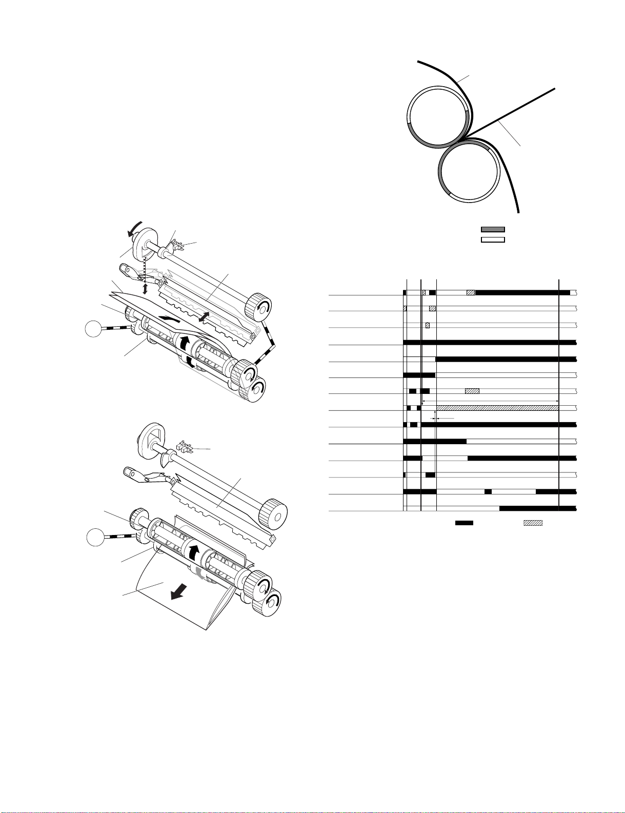
Job offset sequence
Inlet sensor (ES)
Processing tray sensor
(AS)
Feed motor (FFM)
Delivery motor (FAM)
Delivery belt home
position sensor (OBHPS)
Paddle motor (FPM)
Paddle home position
sensor (PHPS)
Swing guide home
position sensor (ARHPS)
Stapler safety switch
(SSS)
Alignment motor (front)
(FFJM)
Aligning plate home position
sensor (front) (FJHPS)
Alignment motor (rear)
(FRJM)
Aligning plate home position
sensor (rear) (RJHPS)
Start signal
Host machine delivery signal
360msec
360msec 360msec
60msec
Swing guide
360msec
30msec
220msec
CW rotation CCW rotation
Slide motor
(FSM)
Paper stack
Stapler
(Deliver direction)
Light-shielding plate
Slide home position sensor (SHPS)
AR-F13 OPERATIONAL DESCRIPTION 4-7
Page 21
B.Stapling Operation
When stacking and alignment of paper on the processing tray are
complete, the finisher controller PCB drives the paddle motor (FPM) in
the reverse direction and lowers the swing guide. When the swing guide
descends, the paper stack is sandwiched between the upper and lower
stack delivery rollers.
The finisher controller PCB moves the stapler for stapling according to
the specified stapling position (when rear 1-point stapling is specified,
the stapler does not move but it staples at the standby position). As the
stapler moves forward, the processing tray stopper is folded forward.
Paper stack
Swing guide
Stack delivery roller (upper)
Processing tray stopper
Delivery tray
Paddle motor (FPM)
Stack
delivery
roller
(lower)
Stapler
Swing guide home
position sensor (ARHPS)
C.Delivery Operation after Stapling
When stapling is complete, the finisher controller PCB drives the deliver
motor in the forward direction to feed the paper stack (sandwiched
between the stack delivery rollers) in the delivery direction. The delivery
belt home position sensor is turned OFF. The delivery motor is driven a
specified number of pulses, causing the swing guide to ascend. At the
same time, the slide motor is driven to return the stapler back to the
standby position, followed by driving of the delivery motor. Then, the
paper stack is delivered with the nails of the delivery belt that rotates in
sync with the stack delivery rollers.
Paper stack
Swing guide
Delivery tray
Delivery belt
Stack delivery
roller (lower)
Stapler
Staple safety switch
(SSS)
Swing guide
Stack delivery roller
Stack delivery roller
(lower)
(upper)
Light-shielding plate
Paddle motor (FPM)
Staple safety switch
(SSS)
Swing guide
Stack delivery roller
Stack delivery roller
(lower)
(upper)
Swing guide home
position sensor (ARHPS)
Light-shielding plate
AR-F13 OPERATIONAL DESCRIPTION 4-8
Page 22
D.Stapler Unit
The staple/fold motor (FFSM) is used to perform stapling operation. This
motor rotates the cam one turn for stapling. The home position of this
cam is detected by the staple home position sensor (STHPS).
The staple/fold motor is rotated in the forward or reverse direction under
the control of the macro computer (IC13) on the finisher controller PCB.
When the staple home position sensor is OFF, the finisher controller
PCB rotates the staple/fold motor in the forward direction until the sensor
turns ON, allowing the staple cam to the original position.
The staple empty sensor (SPS) is used to detect presence/absence of a
staple cartridge in the machine and presence/absence of staples in the
cartridge.
The stale top position sensor (SS) is used to determine whether staples
are pushed up to the top of the staple cartridge.
The finisher controller circuit does not drive the staple/fold motor (FFSM)
unless the staple safety switch (SSS) is ON (the swing guide is close).
This assures safety in case where you happen to put your finger in the
stapler.
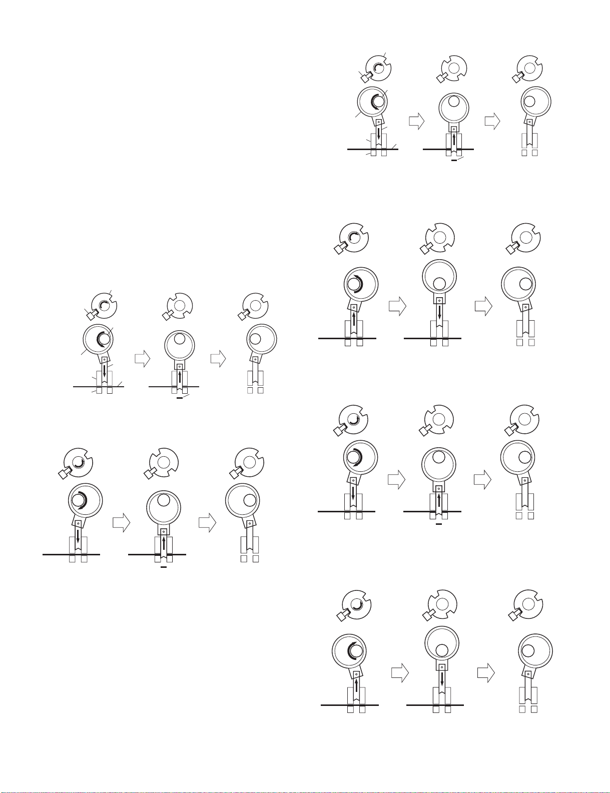
(1)Stapler Movement Controller
The stapler unit is moved by the slide motor (FSM). Its home position is
detected by the slide home position sensor (SHPS). The stapler waits at
the back irrespective of the staple mode and paper size. After paper has
been stacked on the processing tray, the stapler is moved to the
specified stapling position in response to the stapling command from the
host machine.
The standby position of the stapler and the stapling position depending
on the staple mode are shown below.
a.Front 1-point stapling
The stapler waits at the back. The stapler moves to and returns from the
stapling position for each stapling operation.
Standby position
Stapler
Feed direction
Stopper
Stapling position
b.Rear 1-point stapling
The stapler waits at the back. The stapling position is the same as the
standby position.
Standby position
Stabling position
Stapler
Feed direction
Stopper
M7
c.Middle 2-point stapling
The stapler waits at the back. The stapler moves to and returns from the
stapling position for each stapling operation. The stapler first staples a
paper stack at the rear stapling position and then staples it at the front
stapling position.
Standby position
Staple top position detect signal
Staple empty detect signal
Staple home position detect signal
Finisher controller PCB
Staple/hold motor drive signal
Feed direction
AR-F13 OPERATIONAL DESCRIPTION 4-9
Stapler
Stapling position
Stopper
Stapling position
Page 23

d.Middle 2-point stapling (bind mode)
The stapler waits at the back. The stapler moves to and returns from the
stapling position for each stapling operation. The stapler first staples a
paper stack at the rear stapling position and then staples it at the front
stapling position.
Standby position
Stapler
Stapling position
Stopper
Feed direction
Stapling position
Stapling Operation Sequence
Rear 1-point Stapling of 2 Sheets
Start signal
Inlet sensor (ES)
Processing tray sensor
(AS)
Feed motor (FFM)
Delivery motor (FAM)
Delivery belt home
position sensor (OBHPS)
Paddle motor (FPM)
Paddle home position
sensor (PHPS)
Swing guide home
position sensor (ARHPS)
Stapler safety switch
(SSS)
Alignment motor (front)
(FFJM)
Aligning plate home position
sensor (front) (FJHPS)
Staple/fold motor
(FFSM)
Staple home position
sensor (STHPS)
Host machine delivery signal
360msec
360msec
20msec
CW rotation CCW rotation
Staple
Stack delivery
10msec
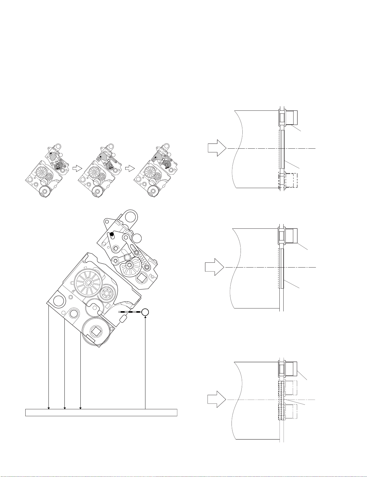
4. Delivery Tray Operation
A.Outline
The machine has a delivery tray in the finisher unit and a bind tray in the
saddle unit.
The bind tray in the saddle unit is of the fixed type and all the folded
paper stacks are delivered to this tray. This tray has a bind tray sensor
(FES) to detect presence/absence of paper.
The delivery tray in the finisher unit is moved up and down using a shift
motor (FLM).
The finisher has a tray paper sensor (BES) to detect presence/absence
of paper on the stack tray.
The home position sensor of the delivery tray is detected by the paper
surface sensor (STHPS). When paper has already been stacked on the
delivery tray, the home position is on the top surface of the stacked
paper. When paper has not yet been stacked on the delivery tray, the
home position is at the position where the edge of the delivery tray is
detected. At power-on, the finisher controller PCB drives the shift motor
(FLM) to return the delivery tray to the home position.
When the paper coming from the processing tray is stacked on the
delivery tray, the shift motor is driven a specified number of pulses,
causing the delivery tray to descend. Clock pulses are detected by the
shift motor clock sensor (LE). Then, the delivery tray returns to the home
position for the next stacking operation.
The upper limit of the delivery tray is detected by the shift upper limit
sensor (ULS). When the shift upper limit sensor (ULS) is turned ON, the
finisher controller PCB stops the shift motor (FLM) that is ascending.
The lower limit of the delivery tray is detected by the shift lower limit
sensor (LLLS). When the shift lower limit sensor (LLLS) is turned ON,
the finisher controller PCB stops the shift motor (FLM) that is
descending.
The finisher unit has a full stack sensor (PI24) to detect overstacking of
large-size or mixed paper according to the stack height.
Shift upper limit sensor
Shift lower limit sensor
Shift motor clock sensor
(ULS)
(LLLS)
(LE)
Tray paper sensor (BES)
Paper surface sensor (SLS)
Edge
Delivery tray
Full stack sensor (XXXX)
AR-F13 OPERATIONAL DESCRIPTION 4-10
Shift motor (FLM)
Page 24

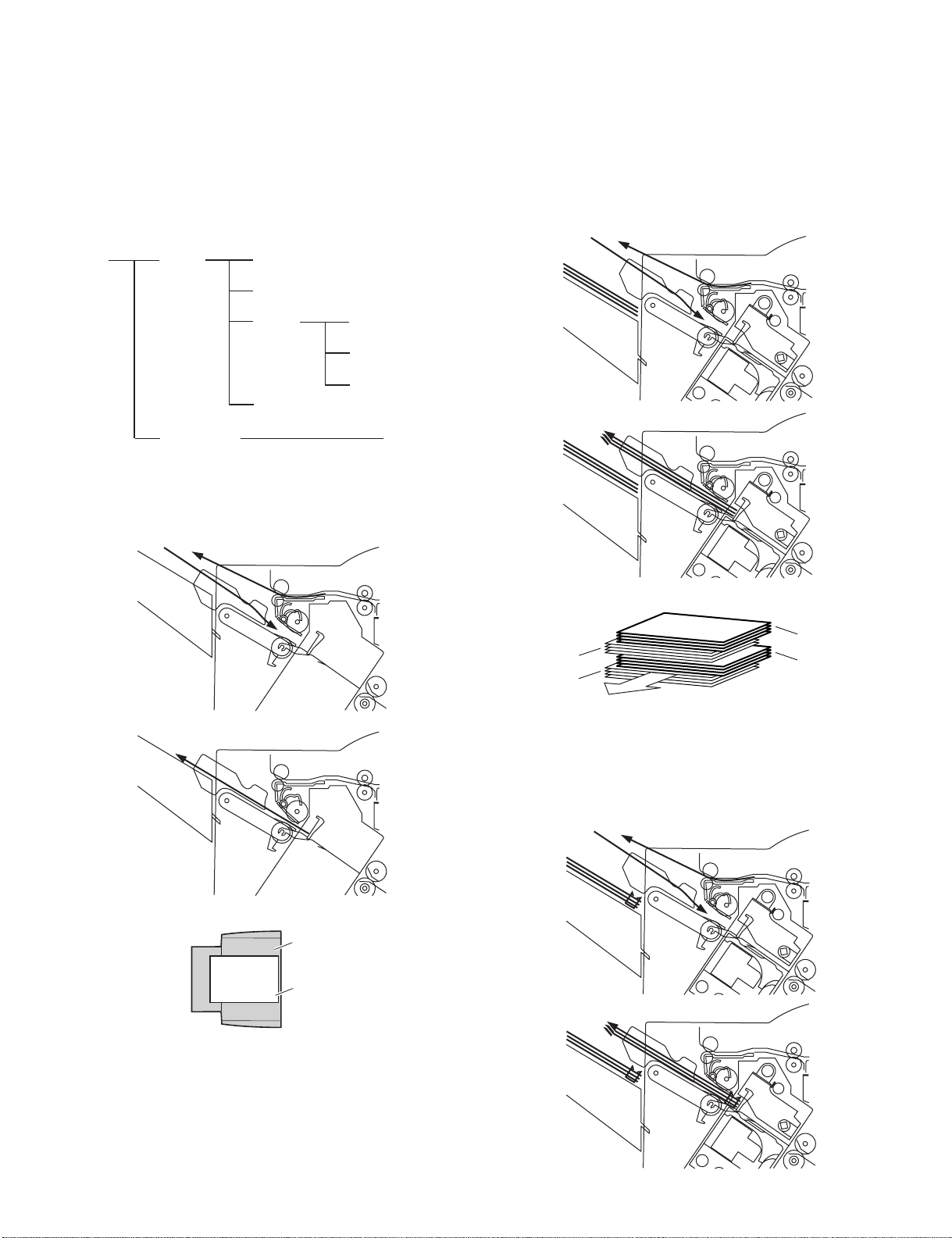
5. Saddle Unit
A.Basic Operations
(1)Outline
The machine stitches a stack of sheets (middle 2-point), then folds the
stack in two in the finisher. These operations are controlled by the
finisher controller PCB.
The finisher controller PCB is controlled by the commands from the host
machine.
B.Feed/Drive System
(1)Outline
This machine stitches the paper stack coming from the finisher, folds it,
and delivers it to the bind tray in the saddle unit in response to the
commands from the host machine.
That is, the machine performs the following operations:
a) Paper feed-in
b) Stitching
c) Stack feed
d) Folding/delivery
b.Stitching
When the center of the paper stack (stitching position) reaches the
stapler's staple position, the stapler stitches the paper stack.
When only one sheet is fed from the host machine, the next step (stack
feed) is performed without performing the stitching operation.
Staple
Stapler (lower)
Stapler (upper)
a) Paper feed-in
d) Folding/delivery
b) Stitching
c) Stack feed
a.Paper feed-in
After being aligned on the processing tray, a stack of sheets is
sandwiched between the stack delivery rollers. As the stack delivery
rollers rotate, the stack is fed toward the saddle unit.
Stack delivery roller (upper)
Paper stack
Stack delivery roller
(lower)
c.Stack feed
The stack feed rollers feed the paper stack to the stack folding/delivery
position where the center of the stack (stitched position) is level with the
paper pushing plate and paper folding roller's nip part.
Stack feed roller (upper)
Paper pushing plate
Stack feed roller (lower)
Paper fold roller
AR-F13 OPERATIONAL DESCRIPTION 4-11
Page 25
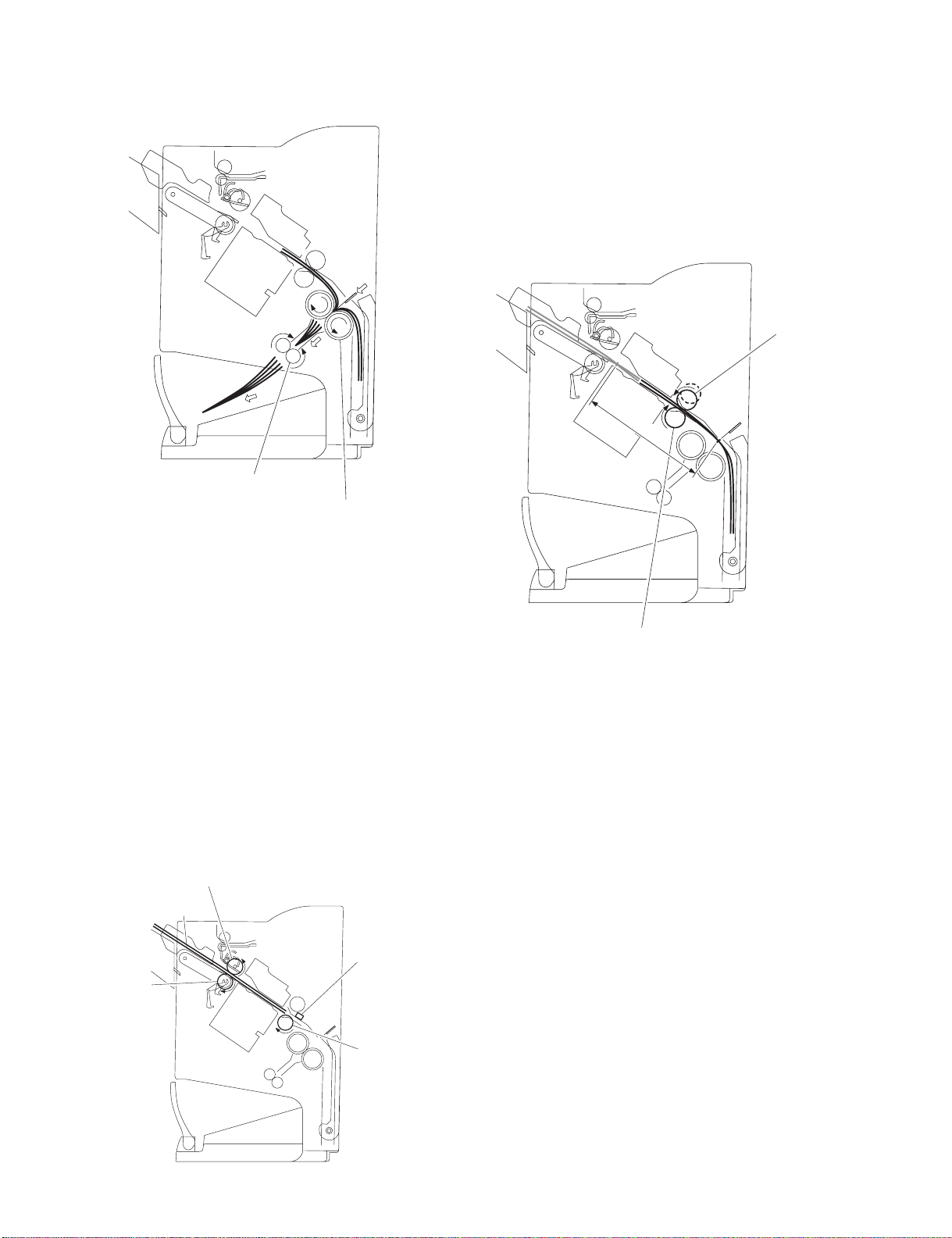
d.Folding/delivery
The paper pushing plate pushes in the center of the paper stack to feed it
toward the paper fold rollers. Then, the paper fold rollers and bind
delivery rollers deliver the paper stack to the bind tray.
Bind delivery rollers
Paper fold rollers
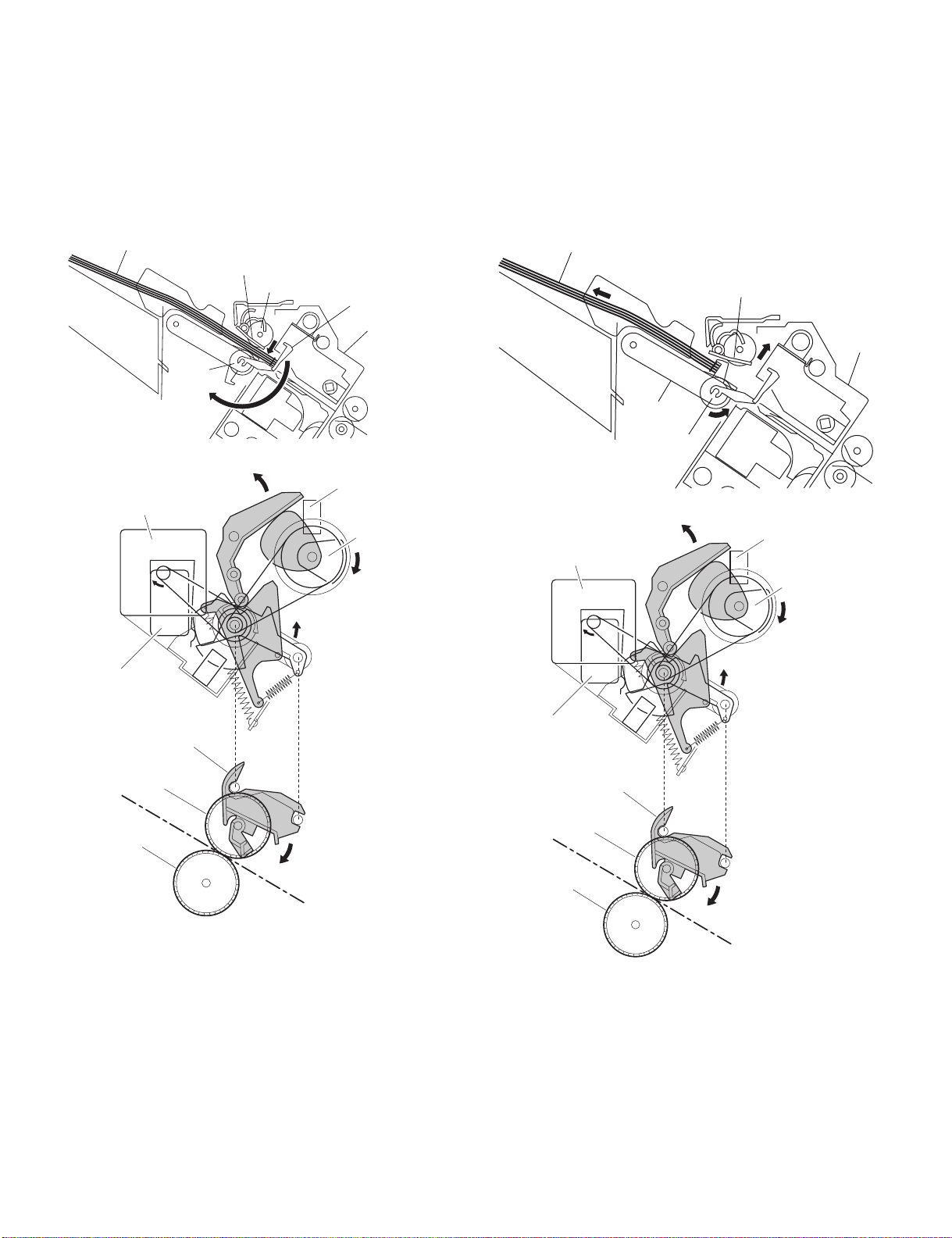
D.Stack Feed System
(1)Outline
The stack feed system feeds the stitched paper stack to the folding
position.
When stitching is complete, the feed motor (FFM) rotates, causing the
stack feed roller (upper) to descend. The paper stack is sandwiched
between the stack feed rollers. Then, the bind clutch (FFC) is turned ON
to rotate the feed motor (FFM) in the forward direction, thus feeding the
paper stack to the folding position. The feed amount is equivalent to the
number of pulses used to drive the feed motor (FFM) until the paper
stack reaches the folding position.
Stack feed roller (upper)
Feed amount
C.Paper Feed System
(1)Outline
The paper feed system feeds a stack of sheets (coming from the finisher)
to the position where the center of the paper stack (stitching position) is
aligned to the stapler's staple, allowing the next step (stitching and
folding) to be performed.
When sheets of paper have been stacked and aligned on the processing
tray, the paddle motor (FPM) rotates in the reverse direction, causing the
swing guide to descend. As the swing guide descends, the paper stack
is sandwiched between the upper and lower stack delivery rollers. The
delivery motor (FAM) rotates in the reverse direction, feeding the paper
stack toward the saddle unit. When the leading edge of the paper stack
reaches the folding position sensor (FPS), the finisher controller PCB
drives the delivery motor a specified number of motor pulses to stop the
center of the paper stack (stitching position) at the stapler's staple
position. Before the paper stack passes through the stack feed rollers,
the feed motor (FFM) is driven to rotate the stack feed roller (lower) so
that the leading edge of the paper stack is not bent.
Stack delivery roller (upper)
Paper stack
Fold position sensor
Stack delivery roller
(lower)
Stack feed roller (lower)
E.Fold/Delivery System
(1)Outline
The paper fold mechanism consists of a guide plate, paper fold rollers,
and a paper pushing plate.
The guide plate, paper fold rollers, and paper pushing plate are driven by
the staple/fold motor (FFSM). The drive force is transferred with a
combination of gears and cams. Motor operation is monitored by the
staple/fold motor lock sensor (FE).
Until the paper stack reaches the folding position, the guide plate covers
the paper fold rollers to act as a paper path through which a paper stack
is fed to the saddle unit and to prevent a paper stack from touching the
rollers.
A folding home position sensor (FHPS) is provided to detect the
positions of the paper fold rollers and paper pushing plate.
The paper stack folded in two by the paper fold rollers is delivered by
bind delivery rollers.
The bind delivery rollers are also driven by the staple/fold motor (FFSM).
A bind tray sensor (FES) is provided on the bind tray to detect presence/
absence of a paper stack; however, it is not used to detect a jam.
Stack feed roller (lower)
AR-F13 OPERATIONAL DESCRIPTION 4-12
Page 26
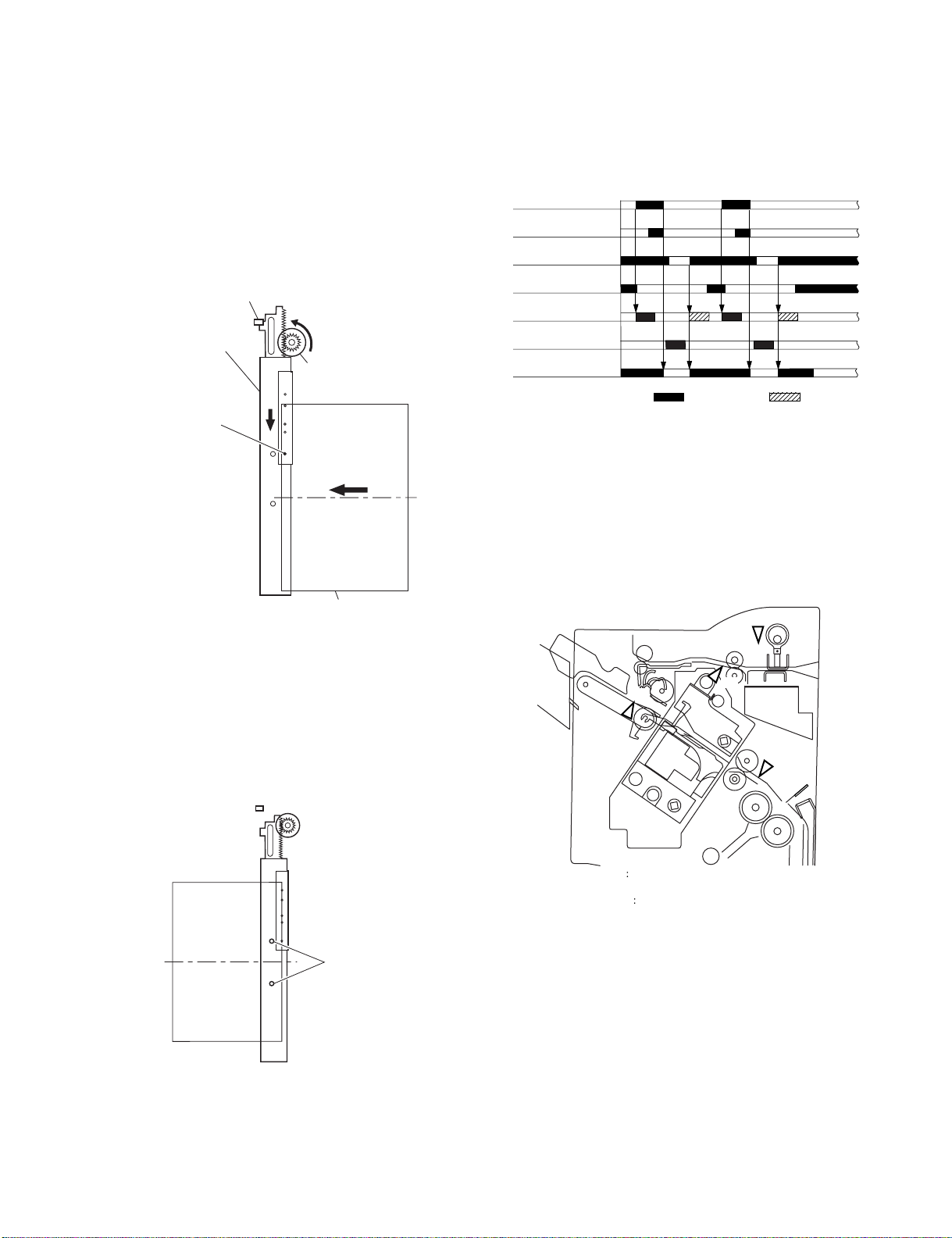
(2)Paper Folding
Paper is folded using paper fold rollers and a paper pushing plate.
Almost concurrently with the start of roller rotation, the paper pushing
plate starts operating to push the paper stack into the gap between the
paper fold rollers. When the paper stack is fed about 10 mm with the
rotation of the paper fold rollers, the paper pushing plate returns to the
home position. Then, the paper stack is delivered to the bind tray using
the paper fold rollers and bind delivery rollers.
Half the entire surface of each paper fold roller is uncovered excluding
the central area and the area at the left and right ends. The uncovered
surface of the upper paper fold roller comes in touch with the uncovered
surface of the lower paper fold roller only at the center and left and right
ends, allowing a paper stack to be fed without causing creases. The
other half of the upper paper fold roller that is covered comes in touch
with the other half of the lower paper fold roller that is also covered,
allowing a paper stack to be folded while being fed.
Sensor flag
Folding home position sensor (FHPS)
Came
Paper stack
Paper fold roller (upper)
Staple/fold
FFSM
motor
Paper fold roller (lower)
Paper fold roller (upper)
Staple/fold
motor
FFSM
Paper pushing plate
Folding
home position sensor (FHPS)
Paper pushing plate
[Paper folding start position]
Outlet
Feed motor (FFM)
Delivery motor (FAM)
Paddle motor (FPM)
Paddle home position
sensor (PHPS)
Swing guide home
position sensor (ARHPS)
Stapler safety switch
(SSS)
Slide motor (FSM)
Staple/fold motor (FFSM)
Staple home position
sensor (STHPS)
Folding position sensor
(FPS)
Stack feed roller (upper)
home position sensor (FRHPS)
Binding cluch (FFC)
Folding home position
sensor (FHPS)
Bind tray sensor (FES)
Staply
Paper stack
Inlet
Paper push plate
Folds/feeds a paper stack.
Feeds a paper stack.
Fold, Delivery
13571msec
50msec
CW rotation CCW rotation
Paper fold roller (lower)
Paper stack
AR-F13 OPERATIONAL DESCRIPTION 4-13
Page 27

6. Puncher Unit (option)
A. Basic Operations
(1)Outline
The puncher unit is an option, and is designed for installation to the
pickup assembly of the finisher. The puncher unit is not equipped with a
paper feeding mechanism, and the sheets from the host machine move
through the puncher unit and then the feed system of the finisher.
When the trailing edge of a sheet from the host machine reaches the
puncher unit, the sheet is stopped once, and the punch shaft is rotated to
punch a hole along the trailing edge. These operations are controlled
with various commands from the finisher controller PCB as well as the
commands from the punch controller PCB.
The punch motor and horizontal registration motor are controlled with
various commands from the finisher controller PCB as well as the
commands from the punch controller PCB.
The waste paper occurring as the result of punching is collected in the
waste paper case. The case is monitored by the LED121 on the waste
full LED PCB and PT131 on the waste full photosensor PCB.
Punch controller PCB (1/2)
Punch drive system
Horizontal registration
drive system
Punch controller PCB
Finisher unit control system
B.Punching Operation
(1)Outline
The puncher unit is located in the pickup assembly of the finisher, and is
used to punch holes in sheets that have been sent from the host
machine and stopped inside it. When the trailing edge of a sheet reaches
the puncher unit, the inlet roller of the finisher assembly stops the sheet
to punch a hole along the trailing edge of the sheet.
The punch unit consists of a die and hole puncher (punch blade).
The hole puncher is driven by the punch motor (FPNM). It is attached to
the eccentric cam of the punch shaft, and the rotation of the punch shaft
is converted into reciprocating motion for punching operation.
The punch motor (FPNM) is a DC motor. The home position of the punch
shaft is detected by the punch home position sensor (PI1P). To make
sure that the punch motor, which is a DC motor, stops exactly at its home
position, the punch motor is stopped in relation to the count of the clock
pulses kept by the punch motor clock sensor (PE).
A single punching operation is executed by rotating the punch shaft 180×
from its home position.
As many as five light-receiving transistors (photosensor PCB) are
mounted over the inlet paper path of the puncher unit; on the other hand,
as many as five LEDs (LED PCB) are mounted under the path, together
serving as five sensors. The frontmost sensor (LED5, PT5) is used to
detect the training edge of sheets, and the remaining four (LED1 through
LED4, PT1 through PT4) are used as horizontal registration sensors to
detect the rear position of sheets when punching holes.
The punch motor, punch unit, and sensors make up the punch slide unit,
which moves to the front/rear to suit the selected paper size. The
movement to the front/rear is driven by the horizontal registration motor
(FPSM). The home position of the punch slide unit is detected by the
horizontal registration home position sensor (PSHPS), and the horizontal
registration motor (FPSM) is a stepping motor.
Trailing edge detection signal
LED121
Punch motor (FPNM) drive
signal
(LED5, PT5) PAEND
Horizonal registration detection
signal (LED1~4, PT1~4) SREG1~4
PT1
2
3
4
5
LED1
2
3
4
5
Punch motor clock (PE)
detection signal PUNCHCLK
Punch controller PCB (2/2)
PT131
Waste full detection signal
(LED121, PT131) DFULL
Punch home position (XXXX)
Horizontal registration home position
(PSHPS) detection signal SREGHP
Horizontal registration motor
(FPSM) drive signal
detection signal PUNCHHP
AR-F13 OPERATIONAL DESCRIPTION 4-14
Page 28
(2)Punching Operation
/
The hole puncher is driven by the punch motor (FPNM). The home
position for the hole puncher is detected by the punch home position
sensor (XXXX).
The punch unit comes in four types, selected to suit the country of
installation: 2-hole (Puncher Unit-J1), 2- and 3-hole (Puncher Unit-K1),
or two types of 4-hole (Puncher Unit-G1, Puncher Unit-H1).
The 2-hole and 4-hole types punch a hole when the punch shaft is
rotated 180× from the home position, causing the punch to make a single
round trip. The 2-/3-hole type punches a hole, but the circumference of
the punch shaft is divided into two (half for 2-hole and the other half for
3-hole).
a.2-Hole, 4-Hole Type
The home position is identified when the punch home position is ON.
The punching operation for the first sheet ends when the punch shaft has
rotated 180× and the punch home position sensor goes ON; the
punching operation for the second sheet ends when the punch shaft has
rotated 180× in reverse and the punch home position sensor goes ON.
The punching operation takes place as follows when making a hole in
two sheets of paper.
1) A hole is punched along the trailing edge of the 1st sheet.
Sensor flag
Punch home position
sensor (PI1P)
Punch shaft
1) A hole is made along the trailing edge of the 1st sheet.
Sensor flag
Punch home position
sensor (PI1P)
Punch shaft
Eccentric cam
Die
Die
(punch shaft at rest/
home position)
Hole
puncher
Paper
(punch shaft CW rotation
by 90˚/hole made)
Waste paper
(punch shaft CW rotation by 180˚/
end of punching operation)
While two holes are being made, the 3-hole puncher makes a single
round trip in escape direction.
Eccentric cam
Die
Die
(punch shaft at rest/
home position)
Hole
puncher
Paper
(punch shaft CW rotation
by 90˚/hole made)
Waste paper
(punch shaft CW rotation by 180˚/
end of punching operation)
2) A hole is made along the trailing edge of the 2nd sheet.
(punch shaft at rest/
home position)
(punch shaft CCW rotation
by 90˚/hole made)
(punch shaft CCW rotation by 180˚/
end of punching operation)
b.2- /3-Hole Type
The home position is identified when the punch home position sensor is
ON. To make two holes, the punching operation for the first sheet ends
when the punch shaft rotates 180° (half circumference) and the punch
home position sensor goes ON. At this time, the 3-hole puncher makes a
single round trip in escape direction (moving up the hole puncher) on a
half circumference of the punch shaft.
The punching operation for the second sheet ends when the Punch shaft
has rotated 180° counterclockwise and the punch home position sensor
goes ON (half circumference). At this time, the 3-hole puncher makes a
single round trip in escape direction (moving up the hole puncher) on the
other half circumference of the punch shaft.
The punching operation takes place as follows when making two holes in
two sheets of paper:
(punch shaft at rest/
home position)
(punch shaft CW rotation by 90˚/
punch at upper limit)
(punch shaft CW rotation by 180˚/
punch back to initial position)
2) Holes are made along the trailing edge of the 2nd sheet.
(punch shaft at rest/
home position)
(punch shaft CCW rotation
by 90
˚/hole made)
(punch shaft CCW rotation by 180˚
end of punching operation)
While two hole are being made, the 3-hole puncher makes a single
round trip in escape direction (moving up the hole puncher).
(punch shaft at rest/
home position)
(punch shaft CCW rotation by
90˚/punch at upper limit)
(punch CCW rotation by 180˚/
punch back at initial position)
AR-F13 OPERATIONAL DESCRIPTION 4-15
Page 29
(3)Horizontal Registration Operation
The horizontal registration drive for the punch slide unit is provided by
the horizontal registration motor (FPSM). The home position of the
punch slide unit is detected by the horizontal registration home position
sensor (PSHPS). The punch slide unit detects the trailing edge of sheets
using the trailing edge sensor (LED5, PT5) and the horizontal
registration sensors (LED1 through 4, SREG1 through 4), and causes a
move to a specific position matching the trailing edge of each sheet
(in relation to the size of the sheet).
The horizontal registration operation takes place as follows:
1) When the leading edge of a sheet from the host machine is detected
by the trailing edge sensor (LED5, PT5), the horizontal registration
motor (FPSM) starts to move the punch slide unit toward the front.
Horizontal registration home
position sensor (P12P)
4) When the punching operation ends, the feed motor (FFM) of the
fisher unit is driven and, at the same time, the horizontal registration
motor (FPSM) is rotated in reverse to return the punch slide unit to
its home position.
5) For each sheet that arrives in succession, the punch slide unit is
returned to its home position, and is caused to repeat steps 1
through 4 .
Trailing edge sensor
(LED5, PT5)
Horizontal registration
sensor (LED1~4, PT1~4)
Punch home position
sensor (XXXX)
Horizontal registration home
position sensor (PSHPS)
Horizontal registration
motor (FPSM)
Punch slide unit
Horizontal registration
motor (M2P)
Trailing edge sensor
(LED5, PT5)
(direction of
paper delivery)
Paper
2) When the horizontal registration sensor (LED1 through 4, PT1
through) suited to the paper size signal from the host machine
detects the rear edge of the sheet, the horizontal registration motor
(FPSM) causes a farther move to a specific position, and stops the
punch slide unit.
3) When the trailing edge sensor (LED5, PT5) detects the trailing edge
of the sheet, the drive of the feed motor (FFM) is stopped, thereby
stopping the sheet. Then, the punch motor (FPNM) is driven to
punch holes in the sheet.
Punch motor (FPNM)
Feed motor (FFM)
: CW rotation : CCW rotation
7. Detecting Jams
A.Outline
The microprocessor (CPU) on the finisher controller PCB is programmed
to check for jams in the finisher/saddle/puncher (option) at such times as
set in advance. It identifies a jam in reference to the presence/absence
of paper at a specific sensor. If a jam is found, the finisher controller PCB
communicates the nature of the jam to the host machine in the form of a
code(which may be checked in service mode of the host machine).
XXX
AS
ES
FPS
Punch
AR-F13 OPERATIONAL DESCRIPTION 4-16
ES: Inlet sensor
Process tray sensor
AS
FPS Folding position sensor
Punch home position sensor
XXX
Page 30
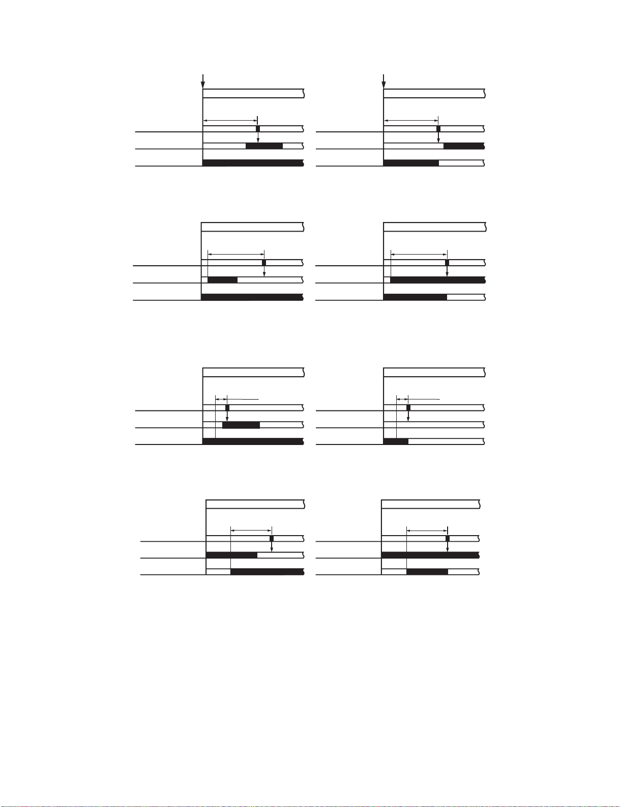
(1)Inlet Sensor Delay Jam
The inlet sensor does not detect paper approximately 1.5 sec after the host machine generates the delivery signal.
Host machine delivery signal
Host machine delivery signal
Jam check
Inlet sensor (ES)
Feed motor (FFM)
approx. 1.5sec.
Normal
Jam check
Inlet sensor (ES)
Feed motor (FFM)
approx. 1.5sec.
Jam
(2)Inlet Sensor Stationary Jam
The paper does not leave the inlet sensor approximately 2 sec after the inlet sensor has detected its leading edge.
Jam check
Inlet sensor (ES)
Feed motor (FFM)
approx. 2sec.
Normal
Jam check
Inlet sensor (ES)
Feed motor (FFM)
approx. 2sec.
Jam
(3)Folding Position Sensor Delay Jam
In bind mode, the folding position sensor does not detect paper 1200 msec after the intermediate processing tray starts to send paper to the stapling
position.
Jam check
Folding position
sensor (FPS)
Delivery motor (FAM)
1200 ms
Normal
Jam check
Folding position
sensor (FPS)
Delivery motor (FAM)
1200 ms
Jam
(4)Folding Position Sensor Stationary Jam
In bind mode, paper does not leave the holding position sensor approximately 10.5 sec after the staple/fold motor is driven.
Jam check
Folding position
sensor (FPS)
Staple/fold
motor (FFSM)
approx. 10.5sec. approx. 10.5sec.
Normal
Jam check
Folding position
sensor (FPS)
Staple/fold
motor (FFSM)
Jam
(5)Power-On Jam
Paper is detected inside the finisher at power-on or when the door is closed.
(6)Door Open Jam (paper present)
The finisher is disconnected from its host machine or the front door, or the upper cover is opened while the system is in operation (paper on the move).
(7)Staple Jam
The staple home position sensor (STHPS) does not go OFF 600 msec after the stapler is driven. Or, it does not return to its home position (where the
sensor goes ON).
AR-F13 OPERATIONAL DESCRIPTION 4-17
Page 31

8. Power Supply System
A.Finisher/Saddle Assembly
(1)Outline
When the host machine is turned on, it supplies the finisher controller PCB with two channels of 24 VDC; one is for the motors and clutches, and the
other is turned into 5 VDC by the regulator IC (IC1) of the finisher controller PCB for use by the sensors and ICs on PCBs.
If a punch unit (option) is installed, power is also supplied to the punch controller PCB.
Some of 24 VDC used to drive motors is cut off when the joint switch (JS), front door switch (FDSW), or stapler safety switch (SSS) is open.
Block diagram of the power supply system:
Front door switch
Joint switch
(JS)
(FDSW)
Stapler safety switch
(SSS)
24 V
Motor
Host
machine
24VP
24VL
Circuit Breaker
(CB1)
Finisher
Controller PCB
(IC1)
Regurator IC
24 V
24 V
Punch controller PCB
(puncher unit; option)
5 V
5 V
Motor
Clutch
Sensor
Logic system
(2)Protective Mechanisms
A circuit breaker (CB1) is monitored to protect the 24 VDC system sued to drive the motors against overcurrent. The 24-V system used to drive the
feed motor (FFM), paddle motor (FPM), and delivery motor (FAM) is equipped with a fuse which melts in the presence of overcurrent.
A.Puncher Unit (option)
(1)Outline
When the host machine is turned on, the puncher unit is supplied by the finisher controller PCB with 24-V and 5-V power.
The 24-V power is used to drive the motors, while the 5-V power is used by sensors and the ICs on the punch controller PCB.
The 24-V power to the motors will be cut off when the joint switch (MS2) or the front door switch (MS1) of the finisher unit is open.
Block diagram for the power supply system:
Finisher
controller
PCB
24 V
Punch controller PCB
5 V
24 V
5 V
5 V
Motors
Sensors
Logic system
(2)Protective Mechanisms
The 24-V system used to drive the punch motor (FPNM) and the horizontal registration motor (FPSM) is equipped with a built-in fuse which melts in the
presence of overcurrent.
AR-F13 OPERATIONAL DESCRIPTION 4-18
Page 32

[5] DISASSEMBLY AND ASSEMBLY
[3]
[1]
1. Finisher Saddle Unit
A. Externals and Controls
4) Remove the three screws [5], and detach the front cover [6].
[6]
[1] [2]
[4]
[5] [6]
[7]
[3]
(1)Removing the Delivery Tray
1) Remove the four screws [1], and detach the delivery tray [2].
[2]
[5]
(3)Removing the Rear Cover
1) Remove the two screws [1] on the pickup side, and remove the
screw [2] on the delivery side; then, detach the rear cover [3].
[1]
(2)Removing the Front Cover
1) Open the front door [1].
2) While picking the claw [2], detach the fold jam releasing dial [3].
3) Remove the two screws [4].
[1] [4]
[3]
[2]
[4]
[3]
[2]
(4)Removing the Upper Cover
1) Open the upper cover [1], and turn the cover band retainer [2] to the
left to remove it.
2) Remove the cover band [3].
[1]
AR-F13 DISASSEMBLY AND ASSEMBLY 5-1
[3]
[2]
Page 33

3) Remove the screw [4], and detach the processing tray rear cover [5];
then, detach the upper.
[6]
[5]
[4]
(6)Removing the Upper Right Cover Assembly
1) Remove the front cover. (See 1.A.(2).)
2) Remove the rear cover. (See 1.A.(3).)
3) Remove the two screws [1] at the front and the two screws [2] at the
rear; then, detach the upper right cover assembly [3].
[3]
[1]
(5)Removing the Processing Tray Upper Cover
1) Remove the front cover. (See 1.A.(2).)
2) Remove the rear cover. (See 1.A.(3).)
3) Remove the upper cover. (See 1.A.(4).)
4) Disconnect the connector [1], and remove the screw [2].
[2]
[1]
5) While lifting the processing tray upper cover [3], disconnect the
connector [4]; then, detach the processing tray upper cover [3].
[3]
[3]
[2]
(7)Removing the Saddle Guide
1) Remove the delivery tray. (See 1.A.(1).)
2) Remove the front cover. (See 1.A.(2).)
3) Remove the rear cover. (See 1.A.(3).)
4) Free the delivery tray support plate (front) [1] and the delivery tray
support plate (rear) [2] to the outside from the rail grooves.
5) Remove the four screws [3].
[3]
[2]
[3]
6) Shift the side guide [4] lightly to the front, and free the engagement
of the paper surface detecting lever (rear) [5]; then, detach the side
guide [4].
[3]
[1]
[3]
[4]
AR-F13 DISASSEMBLY AND ASSEMBLY 5-2
[5]
[4]
Page 34

NOTE: Be sure to mount the side guide after securely fitting the paper
surface detecting lever (rear) [5] in the groove of the paper
surface detecting lever (middle) [6].
After completion of mounting, push the paper surface detecting
lever several times to make sure that side guide is mounted
securely.
(2)Adjusting the Stapler Phase
When the gears or timing belt at the front of the stapler is replaced or
removed for some reason, the staple shooting timing of the (lower unit of
the stapler) does not match the staple bending timing of the staple
clincher (upper unit of the stapler). Adjust the stapler phase following the
procedure described below.
Gear
[5]
[5]
[6]
[6]
B.Feeding System
(1)Removing the Stapler Unit
1) Open the front door [1].
2) Slide out the stapler unit [3] while pressing the stopper [2].
[1]
Timing belt
Gear
1) Detach the gear cover [2] from the staple driver [1].
2) Remove the E-ring [3] to detach the side cover [5] of the staple
clincher [4].
[4]
[3]
[5]
[2]
[1]
[3]
[2]
NOTE: Do not remove the stapler stapler frame shaft. If removed, the
position where the staple driver (lower unit of the stapler) [4]
shoots stables will shift from the position where the staple
clincher (upper unit of the stapler) [5] receives staples.
[5]
[4]
3) Remove the two E-rings [6] to remove the staple jam releasing gear
[7], timing belt [8], and relay gear 1 [9]. Remove the spacer and
spring at the back of the staple jam releasing gear.
4) Remove the screw [10] and spring [11] to remove the belt tensioner
[12].
[7]
[8]
[6]
[11]
[9]
[10]
[12]
AR-F13 DISASSEMBLY AND ASSEMBLY 5-3
Page 35

5) Remove the timing belt [13].
6) Remove the E-ring [14] to remove the staple position check gear
[15].
[15]
[14]
[13]
7) Turn the gear [16] to align the round hole in the staple driver gear
with the round hole [17] at the back.
[16]
9) Turn the gear [19] to align the round hole in the staple clincher cam
with the round hole [20] at the back.
[19]
[20]
10) Insert a pin [21] with a diameter of approximately 2 mm (use of a 2
mm Allen wrench is recommended) in the round hole to secure the
gear.
[17]
8) Insert a pin [18] with a diameter of approximately 2 mm
(use recommended) in the round hole to secure the gear.
[18]
[21]
11) With the gears and cam fixed, install the timing belt [22] on gears
[23] and [24].
[23]
[22]
[24]
AR-F13 DISASSEMBLY AND ASSEMBLY 5-4
Page 36

12) Mount the staple position check gear [27] so that the blue mark [25]
on the staple position check gear is aligned with the round hole [26]
in the frame.
[26]
[25]
(3)Adjusting the Phase of the Gear in the Saddle Unit
If the gears at the front of the saddle unit or the paper fold rollers in the
sale unit are replaced or removed for some reason, adjust the gear
phase following the procedure described below.
1) The paper fold rollers [1] and saddle cam [2] must be positioned as
shown below.
[27]
NOTE: The position where the blue mark is aligned with the round hole is
the home position for stapling. If the staple jam cancel dial is
turned for some reason, the home position deviates, making it
impossible to remove the stapler cartridge. If such a case, the
gear can be returned to the home position by checking blue mark
position. Therefore, it is necessary to mount the gear at the
correct position.
13) Remove the pin securing the gear to the cam.
14) Assemble the spring [28], spacer [29], staple jam releasing gear [30],
timing belt [31], and relay gear [32] and secure them with the E-ring
[33].
[28]
[31]
[2]
[1]
2) With the paper fold rollers and saddle cam positioned as shown in a
figure above, mount gears as shown in a figure below.
•Align the mark (either of two marks) on the saddle cam drive
gear [3] with the mark on the relay gear [4] (on the half of the
periphery where gears with a smaller face width are arranged).
•With the mark on the saddle cam drive gear [3] aligned with the
mark on the relay gear [4], align the other mark on the relay gear
with the rib of the paper folding roller drive gear [5].
[3]
[29]
[30]
[33]
[32]
[4]
[5]
AR-F13 DISASSEMBLY AND ASSEMBLY 5-5
Page 37

(4)Removing the Saddle Unit
1) Remove the front cover. (See 1.A.(2).)
2) Remove the rear cover. (See 1.A.(3).)
3) Open the jam removal cover [1]; then, remove the two screws [2] and
the right stay [3].
[3]
[2]
[2]
(5) Removing the Processing Tray Assembly
1) Remove the processing tray upper cover. (See 1.A.(5).)
2) Remove the side guide. (See 1.A.(7).)
3) Remove the two screws [1], and disconnect the five connectors [2].
[1]
[2]
[1]
4) Turn the fold jam releasing dial assembly [4] to move the paper
retaining plate assembly [5] to the inside.
[5]
[4]
5) Remove the stop ring [6], and detach the timing belt [7].
6) Disconnect the two connectors [8].
[6]
[7]
[2] [2]
4) Pull the processing stopper base [3] to the front, and free the claw [5]
at the front and the claw [6] at the rear of the processing stopper [4].
[6]
[4]
5) Disconnect the three connectors [7].
6) Release the two claws [8] of the harness retainer, and detach the
motor harness [9].
[1]
[5]
[4]
[3]
[8]
7) Remove the three screws [9], and slide out the stapler unit [10]
slightly to the front.
8) Slide out the saddle unit [11] to the front.
[10] [9]
[9] [11]
AR-F13 DISASSEMBLY AND ASSEMBLY 5-6
[9]
[8]
[7]
Page 38

7) Remove the stop ring [10], and detach the timing belt [11].
8) Disconnect the connector [12], and free the harness [14] from the
edge saddle [13].
[12]
[11]
[14]
(6) Removing the Paddle Assembly
1) Remove the processing tray assembly. (See 1.B.(3).)
2) Place the processing tray assembly [1] as shown.
NOTE: Be sure to take care not to damage the aligning plate [2].
[1]
[2]
3) Detach the timing belt [3], and remove the two screws [4].
[10]
9) Remove the two screws [15], and slide the processing tray assembly
[16] to the rear; then, lift it to detach.
[16]
[15]
[13]
[4]
[3]
4) Separate the processing tray assembly [5] and the paddle assembly
[6] as shown.
AR-F13 DISASSEMBLY AND ASSEMBLY 5-7
[4]
[6]
[5]
Page 39

(7)Removing the Staple/Fold Drive Unit
[17]
[15]
[16]
1) Open the front door [1], and slide out the stapler unit [2] slightly to the
front.
[1]
2) Remove the screw [3], and detach the interface retainer [4].
3) Free the six harness retainers [5], and disconnect the connector [6].
4) Free the harness [7] from the harness retainer [5].
5) Free the harness [7] from the edge saddle [8]; then, disconnect the
two connectors [9].
[2]
[9]
9) Remove the screw [15], and free the claw [17] of the harness guide
from the long angle [16] of the base plate.
10) Disconnect the two connectors [18], and free the harness [20] from
the edge saddle [19].
[18]
[20]
[18]
[19]
[7]
[8]
[5]
[6]
[7]
[3]
[7]
[5] [7] [5]
[4]
6) Release the harness retainer [10], and disconnect the connector
[11].
7) Free the harness [12] from the harness retainer [10].
8) Free the harness [12] for the edge saddle [13]; and disconnect the
two connectors [14].
[14]
[5]
[11]
[12]
11) Remove the three screws [21].
[21]
[21]
[21]
12) Remove the screw [22], and detach the staple/fold drive unit [23].
[13]
[10]
[22]
[23]
AR-F13 DISASSEMBLY AND ASSEMBLY 5-8
Page 40

(8)Removing the Feed Motor Unit
1) Remove the rear cover. (See 1.A.(3).)
2) Open the harness retainer [1], and disconnect the two connectors [2].
3) Remove the screw [3], and detach the harness guide [4].
4) Remove the three screws [5], and detach the feed motor unit [6].
[5]
[5]
7) Remove the gear [5], and detach the gear [6] while spreading the
claw.
8) Remove the stop ring [7], and detach the bushing [8].
9) Remove the screw [9], and detach the inlet sensor [10].
10) Remove the lower paper guide [11].
[5]
[8]
[9]
[3]
[4]
[6]
[2]
[1]
(9)Removing the Feed Roller
1) Remove the upper cover. (See 1.A.(4).)
2) Remove the upper right cover assembly. (See 1.A.(6).)
3) Remove the feed motor unit. (See 1.B.(6).)
4) Remove the screw [1].
5) Remove the stop ring [2], and detach the bushing [3].
[10]
[11]
[6]
[7]
11) Remove the feed roller [12].
[12]
(10)Removing the Stack delivery roller (upper)
1) Remove the paddle assembly. (See 1.B.(4).)
2) Place the paddle assembly [1] as shown.
[3]
[1]
6) Remove the two screws [4].
[2]
[4]
[1]
3) Turn the gear [2] in the direction of the arrow to move up the stack
delivery roller assembly (upper) [3].
[3]
[2]
AR-F13 DISASSEMBLY AND ASSEMBLY 5-9
Page 41

4) Push up the stack delivery roller (upper) [4] from below to free the
stack deliver roller (upper) [4] from the shaft [5].
[4]
[5]
5) Shift up the stack delivery roller (upper) [4], and then push it down to
detach the stack deliver roller (upper) [4].
6) Likewise, remove the stack delivery roller (upper) [6] at the front.
[6]
[4]
4) Push up the safety guide [4] from below to free one side of the safety
guide [4] from the shaft [5].
[5]
[4]
5) Push up the safety guide [4] from below to free the safety guide [4]
from the shaft [5].
[4]
(11) Removing the Paddle
1) Remove the paddle assembly. (See 1.B.(4).)
2) Place the paddle assembly [1] as shown.
[1]
3) Turn the gear [2] in the direction of the arrow to move up the stack
delivery roller assembly (upper) [3].
[3]
[5]
6) Remove the paddle [6] in the direction of the arrow.
7) Likewise, remove the other paddle.
[1]
[2]
AR-F13 DISASSEMBLY AND ASSEMBLY 5-10
Page 42

(12)Removing the Stack delivery roller (lower)/Delivery Belt
[17]
1) Remove paddle assembly, and separate it from the processing tray
assembly. (See 1.B.(4).)
2) Slide the aligning plate (front) [2] and the aligning plate (rear) [3] of
the processing tray assembly [1] by sliding them to the outside.
[1]
6) Remove the two stop rings [11]; then, move the two bushings [12] to
the inside.
[12]
[11]
[3]
[2]
3) Remove the processing tray stopper [4].
[4]
4) Remove the screw [5], and detach the paper guide (front) [7] while
freeing the two claws [6].
[5]
[7]
[11]
[12]
7) Remove the four screws [13]; then, lift the stack delivery roller
assembly (lower) [14] to detach.
[13]
[14]
8) Remove the stack delivery roller (lower) [15] and the two delivery
belts [16].
[13]
[16]
[15]
[6]
5) Remove the screw [8]; then, while freeing the claw [9], detach the
paper guide (rear) [10].
[8]
[10]
[9]
NOTE: Be sure to mount them so that the edges [17] of the claws of the
delivery belts are flush.
AR-F13 DISASSEMBLY AND ASSEMBLY 5-11
Page 43

C. PCBs
(1)Removing the Finisher Controller PCB
1) Remove the rear cover. (See 1.A.(3).)
2) Disconnect the 17 connectors [1], and remove the screw [2].
3) Free the PCB retainer [3], and detach the finisher controller PCB [4].
5) Turn the tab [2] on the stapler side in the direction of the arrow so
that that the fixing screw [7] of the slide home position PCB [6] is in
view through the round hole.
6) Remove the fixing screw [7].
[2]
[2]
[1]
[4]
[3]
[1]
[1]
(2)Removing the Slide Home Position PCB
1) Open the front door [1], and turn the tab [2] on the stapler slide in the
direction of the arrow to slide the stapler to the frontmost point.
2) Remove the stapler unit. (See 1.B.(1).)
[1]
[2]
3) Place the stapler unit [3] as shown.
4) Remove the two screws [4], and detach the guide [5].
[6]
[7]
7) Disconnect the connector [8].
8) Remove the flexible cable retainer [9].
9) Free the lock [10] of the connector in the direction of the arrow; then,
detach the flexible cable [11], and then detach the side home
position PCB [12].
[8]
[12]
[10]
[11]
[9]
[4]
[3]
[5]
[4]
AR-F13 DISASSEMBLY AND ASSEMBLY 5-12
Page 44

2. Punch Unit (AR-PN1)
A.Punch Driving System
(1)Removing the Punch Motor
1) Remove the two screws [1].
2) Disconnect the connector [2] to remove the punch motor [3].
[2]
[1]
(2)Removing the Horizontal Registration Motor
1) Disconnect connector [1].
2) Remove the harness [3] from the harness guide [2].
3) Remove the two screws [4] to remove the horizontal registration
motor [5].
[4]
[3]
3) Disconnect the connector [3]
4) Remove the harness [5] from the harness guide [4].
[4]
5) Disconnect the connector [6].
6) Remove the screw [7] and sensor support plate [8].
[6]
[8]
[7]
[3]
[5]
[3]
[1]
[5]
[2]
(3)Removing the Punch Unit
1) Remove the waste case.
2) Remove the screw [1] to detach the jam processing cover [2].
[1]
[2]
7) Remove the screw [9] and washer [10].
8) Disconnect the connector [11].
9) Remove the two screws [12] to detach the base cover [13].
[9]
[10]
[13]
[11]
[12]
AR-F13 DISASSEMBLY AND ASSEMBLY 5-13
Page 45

10)Remove the four screws [14] to remove the upper transmission
[2]
[3]
[2]
[2]
[1]
sensor unit [15] and lower transmission sensor [16].
[15]
B. PCBs
(1)Removing the Punch Controller PCB
1) Remove the two screws [1].
2) Disconnect the five connectors [2] to remove the punch controller
PCB [3].
[14] [14] [14]
[16]
11) Remove the punch unit [18] from the horizontal registration motor
assembly [17].
[17]
[18]
(2)Removing the Photosensor PCB
1) Remove the punch motor. (See 2.A.(1).)
2) Remove the screw [1].
3) Remove the harness [3] from the harness guide [2] on the PCB, then
detach the PCB cover [4].
[1]
[4]
[3]
[2]
4) Disconnect the connector [5] to remove the photosensor PCB [6].
[6]
[5]
AR-F13 DISASSEMBLY AND ASSEMBLY 5-14
Page 46

(3)Removing the LED PCB
1) Remove the waste case.
2) Disconnect connector [1].
3) Remove the harness [3] from the harness guide [2].
(4)Removing the Waste-Full Photosensor PCB
1) Remove the punch controller PCB. (See 2.B.(1).)
2) Remove the two screws [1] to remove the PCB film [2].
[1]
[2]
[2]
4) Remove the screw [4] and washer [5].
5) Disconnect the connector [6].
6) Remove the screw [7] to detach the base cover [8].
[4]
[5]
[8]
[6]
[7]
[3]
[1]
3) Disconnect the connector [3] to remove the waste-full photosensor
PCB [4].
[3]
[4]
(5)Removing the Waste Full LED PCB
1) Remove the screw [1].
2) Disconnect the connector [2] to remove the waste-full LED PCB [3].
7) Remove the screw [9].
8) Disconnect the connector [10] to remove the LED PCB [11].
[9]
[11]
[10]
AR-F13 DISASSEMBLY AND ASSEMBLY 5-15
[2]
[1]
[3]
Page 47

[6] MAINTENANCE
1. Maintenance System Table
Check (Clean, replace, or adjust as necessary.) Clean Replace Adjust Lubricate Move position
A. AR series
Unit name Part name
Transport section Transport rollers
Transport paper
guides
Drive section Gears (Specified position)
Belts
Other Sensors
Discharge brush
Staple un Replace UN at 100K staple.
Staple cartridge User replacement for every 5000pcs.
When
calling
50K 100K 150K 200K 250K 300K 350K 400K Remark
B. DM series
Unit name Part name
Transport section Transport rollers
Transport paper
guides
Drive section Gears (Specified position)
Belts
Other Sensors
Discharge brush
Staple un Replace UN at 100K staple.
Staple cartridge User replacement for every 3000pcs.
When
calling
50K 100K 150K 200K 250K 300K 350K 400K Remark
2. Punch dust process (with the punch unit installed)
1) Pull the grip of the saddle finisher and move it to allow a space
between the machine and the saddle finisher.
2) Slow pull down the punch dust box and remove punch dust. Use a
polyethylene bag, etc. not to disperse punch dust.
3) Replace the punch dust box to the original position.
4) Move the saddle finisher back to the machine.
AR-F13 MAINTENANCE 6-1
Page 48

[7] MACHINE OPERATION
1. Staple sort mode
Collated sets of printouts are stapled and delivered to the offset tray (upper tray). Alternatively, printed paper is stapled at the center and delivered to
the saddle stitch tray (lower tray). The relation among stapling positions, orientation, paper size for stapling, and stapling capacity is shown below.
Stapling positions
Rear corner of
printouts
Center left two
positions of
printouts
Front corner of
printouts
Saddle stitch Saddle stitch stapling cannot
Portrait orientation
Available paper sizes: 8-1/2"
x 11", A4 and B5
Stapling capacity: Up to 50
sheets for any sizes
Same as above
Same as above
be performed in the portrait
orientation.
A. Saddle stitch function
Printed paper is stapled at two positions at the center and is folded in two
with the center down before delivery.
<Example>
Landscape orientation
Available paper sizes: 11" x 17",
8-1/2" x 14", 8-1/2" x 13", 8-1/2"
x 11" R, A3, B4, A4R, and B5R
Stapling capacity: Up to 50
sheets for 8-1/2" x 11"R, A4R
and B5R, and up to 25 sheets
for other sizes
Same as above
Same as above
Available paper sizes: 11" x
17", 8-1/2" x 11"R, A3, B4,
and A4R
Stapling capacity: Up to 10
sheets for any sizes
B. Punch function (only if a punch module is installed)
If the saddle stitch finisher is equipped with a punch module, printed
paper can be punched (two holes) and delivered to the offset tray. The
saddle stitch function and the punch function cannot be used together.
<Example>
{Original 1} {Punch positions}
AR-F13 MACHINE OPERATION 7-1
{Original 2} {Punch positions}
Page 49

2. Setup by the printer driver
A. Setup procedures when the staple function is used
1) Select "PROPERTY" in the setup menu of the printer driver.
2) Click the "MAIN" tab.
3) In the "FINISH" item, select "Stapling position" and "Staple."
B. Setup procedures when the saddle stitch function is used
1) Select "PROPERTY" in the setup menu of the printer driver.
2) Click the "MAIN" tab.
3) In the "DUPLEX PRINT" items, put a check mark to the radio button of "Center binding."
4) Select between the normal-ratio center binding and 2-UP center binding.
5) In the "FINISH" item, select "2-position binding" of "STAPLE."
C. Setup procedures when the punch function is used
1) Select "PROPERTY" in the setup menu of the printer driver.
2) Click the "MAIN" tab.
3) In the "FINISH" items, put a check mark to the check box of "PUNCH."
3. Using the finisher functions in the copy mode
If you touch the [OUTPUT] key on the copy mode basic screen, a screen for selecting the sort/group/staple functions and selecting an exit tray will
appear.
123 45
OUTPUT
SORT
STAPLE
SORT
GROUP
OFFSET
TRAY
OFFSET
8910
1. [GROUP] key
If this function is selected, all copies of the same original will be grouped.
2. [STAPLE SORT] key
If this function is selected, sorted copies will be stapled and delivered to
the offset tray. (not offset stacked)
3. [SORT] key
If this function is selected, each set of copies will be sequentially
delivered.
4. Icon display
The icon of the selected function (sort, staple sort, group or saddle stitch)
is displayed.
5. [OFFSET TRAY] key
If the offset tray is selected, printed sheets will be delivered to the offset
tray. (If the staple sort function is selected, the offset tray will be
automatically selected.)
6. [CENTER TRAY] key
If the center tray is selected, printed paper will be delivered to the exit
tray located at the upper part of the main unit.
67
CENTER
TRAY
SADDLE
STITCH
7. [OK] key
Press to close this screen and to return to the basic screen.
8. [OFFSET] key
If this function is selected (checked), the offset function will be enabled. If
the check mark is cleared, the offset function will be disabled. (If the
staple sort function is selected, the check mark of the offset function will
be automatically cleared.)
9. [SADDLE STITCH] key
Printed paper will be stapled at the center and folded in two with the
center down. If this function is selected, the pamphlet copy function (see
page xx of the copier operation manual) will be automatically set.
10. [PUNCH] key
If a punch module is installed, printed paper can be punched.
* If a function is selected, the corresponding key will be highlighted.
OK
PUNCH
AR-F13 MACHINE OPERATION 7-2
Page 50

[8] ADJUSTMENTS
ON
1234
1. Finisher/saddle unit
A. Adjusting the Folding Position
The folding position is adjusted by matching it with the stapling position.
If you have replaced the finisher controller PCB, you must transfer the
existing settings to the new PCB. Perform the following if the folding
position must be adjusted for some reason.
NOTE:Both the folding and stapling positions may deviate for some type
of paper. In such a case, change the "middle stapling position" in
the user mode of the host machine.
1) Set SW1 on the finisher controller PCB as follows:
ON
12345678
2) Adjust the folding position by pressing the PSW1 or PSW2 on the
finisher controller PCB a required number of times. Pressing the
switch once moves the folding position about 0.16 mm.
•To move the folding position in the "-" direction, press the PSW1.
•To move the folding position in the "+" direction, press the PSW2.
•Pressing the PSW1 and PSW2 at the same time clears the adjustment
value.
- direction
+ direction
2) Adjust the stapling position by pressing the PSW1 or PSW2 on the
finisher controller PCB a required number of times. Pressing the
switch once moves the stapling position about 0.14 mm.
•To move the stapling position in the "-" direction, press the PSW1.
•To move the stapling position in the "+" direction, press the PSW2.
•Pressing the PSW1 and PSW2 at the same time clears the adjustment
value.
- direction
3) When adjustment of the stapling position is complete, set all bits of
the SW1 on the finisher controller PCB to OFF.
4) Enter the bind mode of the host machine and check whether the
stapling position is adjusted properly. If adjusted improperly, adjust
the stapling position again.
+ direction
C. One-page exit mode
This mode is used to increase the accuracy of paper alignment in the
simple load offset mode by discharging paper one by one to the offset
tray.
1) Set the SW1 of the finisher control PWB as shown below.
ON
3) When adjustment of the folding position is complete, set all bits of
the SW1 on the finisher controller PCB to OFF.
4) Enter the bind mode of the host machine and check whether the
folding position is adjusted properly. If adjusted improperly, adjust
the folding position again.
B. Adjusting the Middle 2-Point Stapling Position
The stapling position is adjusted by matching it with the folding position.
If you have replaced the finisher controller PCB, you must transfer the
existing settings to the new PCB. Perform the following if the stapling
position must be adjusted for some reason.
NOTE:Both the folding and stapling positions may deviate for some type
of paper. In such a case, change the "middle stapling position" in
the user mode of the host machine.
1) Set SW1 on the finisher controller PCB as follows:
ON
12345678
12345678
2) Turn on the power.
2. Punch unit (option)
A. Adjusting the Punch Hole Position
This mode requires operation in service mode. The range of hole
displacement is between 3 and -3 in 1-mm increments. A higher setting
will move the hole toward the leading edge of sheet.
(See the Service Manual of the host machine.)
B. Adjusting the Sensor Output
Perform the following when the punch controller PCB, horizontal
registration sensor (photosensor PCB/LED PCB), or waste full sensor
(waste full photosensor PCB/waste full LED PCB) has been replaced.
1) Shift bits 1 through 4 on the DIPSW1001 on the punch controller
PCB as follows:
2) Press SW1002 or SW1003 on the punch controller PCB. A press will
automatically adjust the sensor output.
•The adjustment is over when all LEDs on the punch controller PCB are
ON: LED1001, LED1002, LED1003.
3) Shift all bits of DIPSW1001 to OFF.
AR-F13 ADJUSTMENTS 8-1
Page 51

C. Registering the Number of Punch Hole
Perform the following to store (register) the type of punch unit (number of
holes) in the IC on the punch controller PCB for identification by the
finisher. Be sure to register the type whenever you have replaced the
punch controller PCB.
1) Set bits 1 through 4 on the DIPSW1001 on the punch controller PCB
as follows:
ON
1234
2) Press SW1002 on the punch controller PCB to select the appropriate
number of punch holes.
•Each press on SW1002 moves the selection through the following
(repeatedly from top to bottom).
Number of punch holes LED1001 LED1002 LED1003
2 holes (Puncher Unit-J1) ON OFF OFF
2/3 holes (Puncher Unit-K1) ON ON OFF
4 holes (Puncher Unit-G1) OFF OFF OFF
4 holes (Puncher Unit-H1) OFF OFF ON
3) Press SW1003 on the punch controller PCB twice. The presses will
store the selected number of punch holes on the punch controller
PCB.
•A single press on SW1003 will cause the LED indication to flash;
another press on SW1003 will cause the indication to remain ON to
indicate the end of registration.
4) Shift all bits of DIPSW1001 to OFF.
D. After Replacing the EEP-ROM (IC1001)
1) Turn off the host machine.
2) Set bits 1 through 4 on the DIPSW1001 on the punch controller PCB
as follows:
ON
1234
3) Press SW1002 and SW1003 on the punch controller PCB at the
same time.
•The presses will initialize the EEP-ROM. At the end, all LEDs
(LED1001, LED1002, LED1003) will go ON.
4) Adjust the sensor output, and store the number of punch holes.
E. Setup by the diag simulation of the printer
(1) When installed to the printer model
(AR-C260M, DM-C260P)
1) Select "CONSOLE FIN. SET X" in the diag mode.
CONSOL FIN. SET X
2) Select the setup value to be changed with [ ] [ ] keys.
The adjustable setup values are shown in the table below.
X: Adjustment content Default
value
A Saddle binding position
Setup
range
Change/Setup
value 1
0 - 400 0.0707mm
adjustment
B Saddle folding position
0 - 400 0.0525mm
adjustment
C Front alignment position
0 - 20 0.367mm
adjustment
D Rear alignment position
0 - 20 0.367mm
adjustment
E Staple front one-position
0 - 200 0.04374mm
binding position adjustment
F Staple rear one-position
0 - 200 0.04374mm
binding position adjustment
G Staple 2-position binding
0 - 200 0.04374mm
center adjustment
H Staple 2-position binding pitch 0 - 99 0.04374mm
I Punch center position
0 - 99
adjustment (FR direction)
J Punch hole position
0 - 99 0.105mm
adjustment
(2)When installed to the multi-function model
1) Select "CONSOLE FINISHER SETTING" in SIM 3-10.
SIMULATION 3-10
CONSOLE FINISHER SETTING. SELECT 1-10, AND PRESS START.
1. SADDLE POSITION 2. FOLDING POSITION
3. FRONT ADJUST
4. REAR ADJUST 5. STAPLE REAR
6. STAPLE FRONT 7. STAPLE BOTH
8. STAPLE PITCH 9. PUNCH CENTER
10. PUNCH HOLE
Pressing START key
starts the operation.
SIMULATION 3-10
CONSOLE FINSHER SETTING
1.FOLDING POSITION
Pressing CUSTOM SETTING key
Stops at the end of the operation.
stops the operation.
2) Select a setup item and change the setup value.
The adjustable setup values are shown in the table below.
Adjustment content Default
1 Saddle binding position
value
200 0 - 400 0.0707mm
Setup
range
adjustment
2 Saddle folding position
200 0 - 400 0.0525mm
adjustment
3 Front alignment position
10 0 - 20 0.367mm
adjustment
4 Rear alignment position
10 0 - 20 0.367mm
adjustment
5 Staple front one-position
100 0 - 200 0.04374mm
binding position adjustment
6 Staple rear one-position
100 0 - 200 0.04374mm
binding position adjustment
7 Staple 2-position binding
100 0 - 200 0.04374mm
center adjustment
8 Staple 2-position binding pitch
50 0 - 99 0.04374mm
adjustment
9 Punch center position
50 0 - 99
adjustment (FR direction)
10 Punch hole position
50 0 - 99 0.105mm
adjustment
(paper feed direction)
1
720
Change/Setup
value 1
AR-F13 ADJUSTMENTS 8-2
Page 52

[9] TROUBLESHOOTING
1. Outline
The CPU on the machine's finisher controller PCB is equipped with a
mechanism to check the machine condition as needed; when it detects a
fault, the machine communicates the fact to the host machine in the form
of a code and a detail code.
The host machine indicates the code on its control panel.
(The detail code may be checked in the host machine's service mode.)
2. Trouble code
F1 03 Content Console finisher (AR-F13)
Detail Paddle motor operation abnormality
Cause Motor lock
Check and
remedy
06 Content Console finisher (AR-F13)
Detail Slide motor operation abnormality
Cause Motor lock
Check and
remedy
10 Content Console finisher (AR-F13)
Detail Stapler motor operation abnormality
Cause Motor lock
Check and
remedy
11 Content Console finisher (AR-F13)
Detail Bundle exit motor operation abnormality
Cause Motor lock
Check and
remedy
15 Content Console finisher (AR-F13) lift motor trouble
Detail Lift motor operation abnormality
Cause Motor lock
Check and
remedy
19 Content Console finisher (AR-F13)
Detail Front alignment motor operation abnormality
Cause Motor lock
Check and
remedy
paddle motor trouble
Motor rpm abnormality
Overcurrent to the motor
Console finisher control PWB trouble
Use DIAG (SIM3-3) to check the motor
operation.
slide motor trouble
Motor rpm abnormality
Overcurrent to the motor
Console finisher control PWB trouble
Use DIAG (SIM3-3) to check the motor
operation.
stapler motor trouble
Motor rpm abnormality
Overcurrent to the motor
Console finisher control PWB trouble
Use DIAG (SIM3-3) to check the motor
operation.
bundle exit motor trouble
Motor rpm abnormality
Overcurrent to the motor
Console finisher control PWB trouble
Use DIAG (SIM3-3) to check the motor
operation.
Motor rpm abnormality
Overcurrent to the motor
Console finisher control PWB trouble
Use DIAG (SIM3-3) to check the motor
operation.
front alignment motor trouble
Motor rpm abnormality
Overcurrent to the motor
Console finisher control PWB trouble
Use DIAG (SIM3-3) to check the motor
operation.
F1 20 Content Console finisher (AR-F13)
rear alignment motor trouble
Detail Rear alignment motor operation abnormality
Cause Motor lock
Check and
remedy
30 Content Console finisher (AR-F13)
Detail Communication cable test error after turning
Cause Improper connection or disconnection of
Check and
remedy
31 Content Console finisher (AR-F13)
Detail Sensor input value abnormality
Cause Sensor breakage
Check and
remedy
32 Content Communication trouble between the console
Detail Communication err between the console
Cause Improper connection or disconnection of
Check and
remedy
33 Content Console finisher (AR-F13)
Detail Punch side registration motor operation
Cause Motor lock
Check and
remedy
Motor rpm abnormality
Overcurrent to the motor
Console finisher control PWB trouble
Use DIAG (SIM3-3) to check the motor
operation.
communication trouble
on the power or exiting from DIAG.
Communication error with the console
finisher
connector and harness between the machine
and the console finisher.
Console finisher control PWB trouble
Control PWB (PCU) trouble
Malfunction by noises
Canceled by turning OFF/ON the power.
Check connectors and harness in the
communication line.
Replace the console finisher control PWB or
PCU PWB.
fold sensor trouble
harness breakage
Console finisher control PWB trouble
Use DIAG (SIM3-2) to check the sensor
operation.
finisher (AR-F13)
and the punch unit (AR-PN1).
finisher and the punch unit.
connector and harness between the console
finisher and the punch unit.
Console finisher control PWB trouble
Control PWB (PCU) trouble
Malfunction by noise
Canceled by turning OFF/ON the power.
Check connectors and harness in the
communication line.
Replace the console finisher control PWB.
punch (AR-PN1) side registration motor
trouble
abnormality
Motor rpm abnormality
Overcurrent to the motor
Console finisher control PWB trouble
Use DIAG (SIM3-3) to check the motor
operation.
AR-F13 TROUBLESHOOTING 9-1
Page 53

F1 34 Content Console finisher (AR-F13)
punch (AR-PN1) motor trouble
Detail Punch motor operation abnormality
Cause Motor lock
Check and
remedy
35 Content Console finisher (AR-F13)
Detail Sensor input value abnormality
Cause Sensor breakage
Check and
remedy
36 Content Console finisher (AR-F13)
Detail Sensor input value abnormality
Cause Sensor breakage
Check and
remedy
Motor rpm abnormality
Overcurrent to the motor
Console finisher control PWB trouble
Use DIAG (SIM3-3) to check the motor
operation.
punch (AR-PN1) side registration sensor
trouble
Harness disconnection
Console finisher control PWB trouble
Use DIAG (SIM3-2) to check the sensor
operation.
punch (AR-PN1) timing sensor trouble
Harness disconnection
Console finisher control PWB trouble
Use DIAG (SIM3-2) to check the sensor
operation.
F1 37 Content Console finisher (AR-F13)
Detail Backup RAM contents are disturbed.
Cause Console finisher control PWB trouble
Check and
remedy
38 Content Console finisher (AR-F13)
Detail Punch unit backup RAM contents are
Cause Punch control PWB trouble
Check and
remedy
81 Content Console finisher transport motor abnormality
Detail Transport motor trouble
Cause Motor lock
Check and
remedy
backup RAM trouble
Malfunction by noise
Replace the console finisher control PWB.
punch (AR-PN1) backup RAM trouble
disturbed.
Malfunction by noise
Replace the punch control PWB.
Motor rpm abnormality
Overcurrent to the motor
Console finisher control PWB trouble
Use DIAG (SIM3-3) to check the motor
operation.
3. Troubleshooting
A. Finisher/saddle unit
(1) F1-03, Paddle Motor Fault (detail code: 01/02/03/04)
Cause/Trouble section Procedure Check Result Remedy
Paddle home position sensor (PHPS) 1 Check the paddle home position sensor. Is the sensor normal? NO Replace the sensor
Swing guide home position sensor
(ARHPS)
Wiring 3 Is the wiring between the finisher controller PCB and the paddle
Paddle, Swing guide assembly 4 Try turning the paddle motor clockwise and counterclockwise by
Paddle motor (FPM),
finisher controller PCB
(2) F1-10, Staple/fold Motor Fault
Cause/Trouble section Procedure Check Result Remedy
Stapler home position sensor (STHPS) 1 Check the stapler home position sensor. Is the sensor normal? NO Replace the sensor.
Wiring 1 Is the wiring between the finisher controller PCB and the staple/
Stapler unit 2 Try turning the staple jam releasing dial.
Staple/fold motor (FFSM),
Finisher controller PCB
2 Check the swing guide home position sensor.
Is the sensor normal?
motor normal?
hands. Is there mechanical tapping in the rotation of the paddle
or the up/down movement of the swing guide?
5 Try replacing the paddle motor. Is the problem corrected? YES End.
fold motor normal?
Is there mechanical trapping?
3 Try replacing the staple/fold motor. Is the problem corrected? YES End.
NO Replace the sensor.
NO Correct the wiring.
YES Correct the
mechanical
mechanism.
NO Replace the finisher
controller PCB.
NO Correct the wiring.
YES Correct the
mechanical system.
NO Replace the finisher
controller PCB.
AR-F13 TROUBLESHOOTING 9-2
Page 54

(3) F1-10, Staple/Fold Motor Fault
Cause/Trouble section Procedure Check Result Remedy
Staple/fold clock sensor (FE) 1 Check the staple/fold clock sensor. Is the sensor normal? NO Replace the sensor.
Finisher controller PCB,
Stapler unit
Staple/fold motor (FFSM),
Finisher controller PCB
2 Does the staple/fold motor operate at the appropriate timing? YES Replace the finisher
controller PCB.
NO Check the stapler unit
drive mechanism:
if faulty, correct it;
if normal, go to step 3).
3 Try replacing the staple/fold motor. Is the problem corrected? YES End.
NO Try replacing the
finisher controller
PCB.
(4) F1-10, Staple/Fold Motor Fault
Cause/Trouble section Procedure Check Result Remedy
Folding home position sensor (FHPS) 1 Check the folding home position sensor. Is the sensor normal? NO Replace the sensor.
Wiring 2 Is the wiring between the finisher controller PCB and the staple/
fold motor normal?
Saddle unit 3 Try turning the fold jam releasing dial.
Staple/fold motor (FFSM),
Finisher controller PCB
Is there mechanical trapping?
4 Try replacing the staple/fold motor. Is the problem corrected? YES End.
NO Correct the wiring.
YES Correct the
mechanical
mechanism.
NO Replace the finisher
controller PCB.
(5) F1-10, Staple/Fold Motor Fault
Cause/Trouble section Procedure Check Result Remedy
Staple/fold clock sensor (FJHPS) 1 Check the staple/fold clock sensor. Is the sensor normal? NO Replace the sensor.
Finisher controller PCB, Saddle unit 2 Does the staple/fold motor operate at the appropriate timing? YES Replace the finisher
controller PCB.
NO Check the saddle unit
drive mechanism:
if faulty, correct it;
otherwise, go to step 3).
Staple/fold motor (FFSM),
Finisher controller PCB
3 Try replacing the staple/fold motor. Is the problem corrected? YES End.
NO Replace the finisher
controller PCB.
(6) F1-10, Slide Motor Fault
Cause/Trouble section Procedure Check Result Remedy
Slide home position sensor (SHPS) 1 Check the slide home position sensor. Is the sensor normal? NO Replace the sensor
Wiring 2 Is the wiring between the finisher controller PCB and the slide
motor normal?
Stapler unit 3 Is there mechanical trapping in the stapler path? YES Correct the
Slide motor (FSM),
Finisher controller PCB
4 Try replacing the slide motor. Is the problem corrected? YES End.
PCB.
NO Correct the wiring.
mechanical system.
NO Replace the finisher
controller PCB.
(7) F1-11, Delivery Motor Fault
Cause/Trouble section Procedure Check Result Remedy
Delivery belt home position sensor
(OBHPS)
Wiring 2 Is the wiring between the finisher controller PCB and the delivery
Stack delivery roller 3 Try turning the stack delivery roller by hand.
Delivery motor (FAM),
Finisher controller PCB
1 Check the delivery belt home position sensor.
Is the sensor normal?
motor normal?
Is the rotation smooth?
4 Try replacing the delivery motor. Is the problem corrected? YES End.
NO Replace the sensor.
NO Correct the wiring.
NO Correct the
mechanical system.
NO Replace the finisher
controller PCB.
AR-F13 TROUBLESHOOTING 9-3
Page 55

(8) F1-15, Shift Motor Fault
Cause/Trouble section Procedure Check Result Remedy
Paper surface sensor (SLS) 1 Check the paper surface sensor. Is the sensor normal? NO Replace the sensor.
Tray up/down mechanism 2 Check the tray up/down mechanism. Is the mechanism normal? NO Correct the
Finisher controller PCB 3 Is 24 VDC supplied from the finisher controller PCB to the shift
motor as soon as the tray is driven?
Shift motor (FLM), Wiring 4 Is the wiring between the finisher controller PCB and the shift
motor normal?
mechanism.
NO Replace the finisher
controller PCB.
YES Replace the shift
motor.
NO Correct the wiring.
(9) F1-15, Shift Motor Fault
Cause/Trouble section Procedure Check Result Remedy
Tray position 1 Is the tray as far as the shift upper limit sensor? YES Lower the position of
the tray.
Shift upper limit sensor (ULS) 2 Check the shift upper limit sensor. Is the sensor normal? NO Replace the sensor.
Finisher controller PCB, Wiring 3 Check the wiring from the finisher controller PCB to the shift
upper limit sensor; is it normal?
YES Replace the finisher
controller PCB.
NO Correct the wiring.
(10) F1-15, Shift Motor Fault
Cause/Trouble section Procedure Check Result Remedy
-
Finisher controller PCB 2 Is power supplied to the finisher controller PCB as soon as the
Tray up/down mechanism,
Shift motor (FLM)
Shift motor clock (LE),
Finisher controller PCB
1 Is the tray in UP position? YES Go to step 4).
NO Go to step 2).
tray is driven?
3 Is there a fault in the tray up/down mechanism? YES Correct the tray up/
4 Check the shift motor clock sensor. YES Replace the finisher
YES Go to step 3).
NO Replace the finisher
controller PCB.
down mechanism.
NO Replace the shift
motor.
controller PCB.
NO Replace the sensor.
(11) F1-19, Alignment Motor (front) Fault
Cause/Trouble section Procedure Check Result Remedy
Aligning plate home position sensor
(front; FJHPS)
Wiring 2 Is the wiring between the finisher controller PCB and the front
Aligning plate (front) 3 Is there mechanical trapping in the aligning plate path? YES Correct the
Alignment motor (front; FFJM),
Finisher controller PCB
1 Check the aligning plate home position sensor (front).
Is the sensor normal?
alignment plate motor (front) normal?
4 Try replacing the Alignment motor (front).
Is the problem corrected?
NO Replace the sensor.
NO Correct the wiring.
mechanical system.
YES End.
NO Replace the finisher
controller PCB.
(12) F1-20, Alignment Motor (Rear) Fault
Cause/Trouble section Procedure Check Result Remedy
Aligning plate home position sensor
(rear; RJHPS)
Wiring 2 Is the wiring between the finisher controller PCB and the rear
Aligning plate (rear) 3 Is there mechanical trapping in the path of the aligning plate? YES Correct the
Alignment motor (rear; FRJM),
Finisher controller PCB
1 Check the aligning plate home position sensor (rear).
Is the sensor normal?
alignment motor (rear) normal?
4 Try replacing the alignment motor (rear).
Is the problem corrected?
NO Replace the sensor.
NO Correct the wiring.
mechanical
mechanism.
YES End.
NO Replace the finisher
controller PCB.
AR-F13 TROUBLESHOOTING 9-4
Page 56

(13) F1-30, Communication error
Cause/Trouble section Procedure Check Result Remedy
Finisher controller PCB,
Host machine DC controller PCB
Wiring 2 Is the wiring between the finisher controller PCB and the DC
Finisher controller PCB,
Host machine DC controller PCB
1 Turn off and then on the host machine. Is the problem corrected? YES End.
controller PCB of the host machine normal?
3 Try replacing the finisher controller PCB and the host machine
DC controller PCB. Is the problem corrected?
NO Correct the wring.
YES End.
(14) F1-37, Finisher Unit Back-Up Memory Fault
Cause/Trouble section Procedure Check Result Remedy
Finisher controller PCB 1 Turn off and then on the host machine. Is the problem corrected? YES End.
NO Replace the finisher
controller PCB.
(15) F1-80, Finisher Unit Power Supply Fault
Cause/Trouble section Procedure Check Result Remedy
Finisher controller PCB,
Host machine DC controller PCB
Wiring 2 Is the wiring between the finisher controller PCB and the host
Power supply 3 Measure the voltage between CN1-1 (+) and CN1-3 (-)/CN2-1 (+)
1 Turn off and then on the host machine. Is the problem corrected? YES End.
machine DC controller PCB normal?
and CN2-3 (-) on the finisher controller PCB. Is it 24 VDC?
NO Correct the wiring.
YES Replace the finisher
controller PCB.
NO Replace the host
machine DC controller
PCB.
(16) F1-81, Feed Motor Fault
Cause/Trouble section Procedure Check Result Remedy
Stack feed roller (upper)
home position sensor (FRHPS)
Wiring 2 Is the wiring between the finisher controller PCB and the feed
Feed roller 3 Try turning the stack feed roller (upper) shaft by hand.
Feed motor (FFM),
Finisher controller PCB
1 Check the stack feed roller (upper) home position sensor.
Is it normal?
motor normal?
Does the stack feed roller (upper) move up/down normally?
4 Try replacing the feed motor. Is the problem corrected? YES End.
B. Puncher unit, option
(1) F1-32, Communication Faulty
Cause/Trouble section Procedure Check Result Remedy
Finisher controller PCB,
Punch controller PCB
Wiring 2 Is the wiring between the finisher controller PCB and the punch
Power supply 3 Measure the voltage between CN14-5 (+) and CN14-3 (-) on the
(2) F1-33, Horizontal Registration Motor Fault (detail code: 01/02)
Cause/Trouble section Procedure Check Result Remedy
Horizontal registration home position
sensor (PSHPS)
Wiring 2 Is the wiring between the finisher controller PCB and the
Horizontal registration mechanism,
horizontal registration motor (FPSM)
Punch controller PCB,
Finisher controller PCB
1 Turn off and the on the host machine. Is the problem corrected? YES End.
controller PCB normal?
finisher controller PCB. Is it 24 VDC?
1 Check the horizontal registration home position sensor.
Is the sensor normal?
horizontal registration home position sensor normal?
3 Is there a fault in the horizontal registration mechanism? YES Correct the horizontal
4 Try replacing the punch controller PCB. Is the problem corrected? YES End.
NO Replace the sensor.
NO Correct the wiring.
NO Correct the
mechanical system.
NO Replace the finisher
controller PCB.
NO Correct the wiring.
NO Replace the finisher
controller PCB.
YES Replace the punch
controller PCB.
NO Replace the sensor.
NO Correct the wiring.
registration
mechanism.
NO Replace the horizontal
registration motor.
NO Replace the finisher
controller PCB.
AR-F13 TROUBLESHOOTING 9-5
Page 57

(3) F1-34, Punch Motor Fault
Cause/Trouble section Procedure Check Result Remedy
Punch motor home position sensor
(XXXX)
Punch motor clock sensor (PE) 2 Check the punch motor clock sensor. Is the sensor normal? NO Replace the sensor.
Wiring 3 Is the wiring between the finisher controller PCB and the sensor
Punch mechanism,
Punch motor (FPNM)
Punch controller PCB,
Finisher controller PCB
1 Check the punch home position sensor. Is the sensor normal? NO Replace the sensor.
NO Correct the wiring.
normal?
4 Is there a fault in the punch mechanism? YES Correct the punch
mechanism.
NO Replace the punch
motor.
5 Try replacing the punch controller PCB. Is the problem corrected? YES End.
NO Replace the fisher
controller PCB.
(4) F1-35, Punch Sensor (horizontal registration) Fault
Cause/Trouble section Procedure Check Result Remedy
Horizontal registration sensor
(photosensor PCB/LED PCB)
Wiring 2 Is the wiring between the punch controller PCB and the horizontal
Punch controller PCB,
Finisher controller PCB
1 Check the horizontal registration sensor. Is the sensor normal? NO Replace the sensor.
NO Correct the wiring.
registration sensor normal?
3 Try replacing the punch controller PCB. Is the problem correct? YES End.
NO Replace the finisher
controller PCB.
(5) F1-38, Puncher Back-UP Memory Fault
Cause/Trouble section Procedure Check Result Remedy
EEP-ROM (IC1002) 1 Is the problem corrected by initializing the EEP-ROM on the
punch controller PCB?
Punch controller PCB 2 Turn off and the on the host machine. Is the problem corrected? YES End.
YES End.
NO Replace the punch
controller PCB.
(6) F1-39, Punch sensor (waste full) Fault
Cause/Trouble section Procedure Check Result Remedy
Waste full Sensor
(waste full photosensor PCB/
waste full LED PCB)
Wiring 2 Is the wiring between the punch controller PCB and the waste full
Punch controller PCB,
Finisher controller PCB
1 Check the waste full sensor. Is the sensor normal? NO Replace the sensor.
sensor normal?
3 Try replacing the punch controller PCB. Is the problem corrected? YES End.
(7) F1-40, Puncher Unit Power Supply Fault
Cause/Trouble section Procedure Check Result Remedy
Finisher controller PCB,
Host machine DC controller PCB
Wiring 2 Is the wiring between the finisher controller PCB and the punch
Power supply 3 Measure the voltage between CN14-5 (+) and CN4-3 (-) on the
1 Turn off and then off the host machine. Is the problem corrected? YES End.
controller PCB normal?
finisher controller PCB. Is it 24 VDC?
NO Correct the wiring.
NO Replace the finisher
controller PCB.
NO Correct the wiring.
YES Replace the punch
controller PCB.
NO Replace the finisher
controller PCB.
AR-F13 TROUBLESHOOTING 9-6
Page 58

[10] SIMULATIONS
1. Finisher/Saddle unit
Error Condition Timing of detection Operation Resetting
Staple absent The stapler is not set. Monitoring at all times The staple/fold motor (FFSM) and the
Staple absent The staple cartridge has run out of
staples.
Mixed sheets Sheets of different sizes are deposited
Overstacking for
stapling
Stack tray
overstacking
Saddle overstacking Remove the stack from the bind tray.
in the compartment.
The number of sheets in the
compartment has exceeded the limit
imposed on stapling.
The number of sheets deposited on the
delivery tray has exceeded the limit
imposed on the tray (sheets, sets).
More than 10 stacks are deposited on
the folded stack tray.
Monitoring at all times Normal operation will continue;
When a sheet of a
different size is placed.
When an extra sheet is
placed.
When an extra sheet is
placed.
When an extra sheet is
placed.
2. Puncher unit (option)
Error Condition Timing of detection Operation Resetting
Waste case full The amount of waste paper in the
waste case has reached the limit.
Excess water The amount of waste paper in the
waste case has exceeded the limit.
During punching. Normal operation will continue. Remove the waste
During punching. Punching will be disabled. Remove the waste
slide motor (FSM) will stop.
however, operation is subject to
instructions from the host machine.
The sheet will be aligned based on
maximum size width and delivered as a
stack.
The sheets will be delivered with
stapling. -
Normal operation will continue. Remove the sheets
Normal operation will continue. Remove the stack from
Set the stapler.
Replace the staple
cartridge;
or, set it correctly.
-
from the delivery tray.
the bind tray.
paper from the waste
case.
paper from the water
case.
AR-F13 SIMULATIONS 10-1
Page 59

[11] ELECTRICAL SECTION
1. LEDs and Check Pins by PCB
Of the LEDs and check pins used in the machine, those needed during servicing in the field are discussed.
NOTE:Do not touch the check pins not found in the list herein. They are exclusively for factory use, and require special tools and a high degree of
accuracy.
A. Finisher Controller PCB B. Punch Controller PCB
CN3
16
CN13
10
31
CN19
CN11
7
9
1
CN7
91
151121
CN5 CN4
CN15
13
17
J1007
1
J1005
14
SW1001
1
59
SW1002
J1003
SW1003
LED1001
LED1002
LED1003
J1004
1
J1002 J1001 J1006
5110
1
1
2
1
12
15
3
1
6
51
17
CN2 CN14 CN1
CN12
CN16
6
CN17
CN8
CB1
LED3
1
1
LED2
PSW2
SW1
4
CN6
LED1
PSW1PSW3
12
CN18
1
CN10
12
1
CN9
1
1
Switch Description
SW1 Folding position adjustment, middle 2-point stapling
adjustment etc.
PSW1 Folding position adjustment, middle 2-point stapling
adjustment etc.
PSW2 Folding position adjustment, middle 2-point stapling
adjustment etc.
PSW3 Factory mode
Switch Description
SW1001 Punch hole count registration/sensor output adjustment
etc.
SW1002 Punch hole count registration/sensor output adjustment
etc.
SW1003 Punch hole count registration/sensor output adjustment
etc.
AR-F13 ELECTRICAL SECTION 11-1
Page 60

2. Wiring diagram (AR-F13)
CN23-3
CN23-2
CN23-1
CN24-3
CN24-2
CN24-1
CN25-3
CN25-2
CN25-1
CN30-3
CN30-2
CN30-1
CN31-3
CN31-2
CN31-1
CN32-3
CN32-2
CN32-1
CN35-3
CN35-2
CN35-1
CN36-3
CN36-2
CN36-1
CN39-3
CN39-2
CN39-1
CN40-3
CN40-2
CN40-1
CN41-3
CN41-2
CN41-1
CN44-3
CN44-2
CN44-1
CN47-3
CN47-2
CN47-1
CN48-3
CN48-2
CN48-1
CN49-3
CN49-2
CN49-1
CN50-3
CN50-2
CN50-1
CN51-3
CN51-2
CN51-1
CN52-3
CN52-2
CN52-1
CN55-3
CN55-2
CN55-1
D
D
D
D
C
C
C
C
B
B
B
B
A
A
A
A
FJHPS
TCS
FDS
AS
OBHPS
BES
SLS
RJHPS
FPS
FHPS
FRHPS
ES
FES
LE
LLLS
ULS
PHPS
FE
ARHPS
sensor (front)
Aligning plate
home position
sensor
Upper cover
sensor
Front door
tray
sensor
Processing
sensor
Delivery belt
home position
sensor
Tray paper
sensor
Paper surface
sensor (rear)
Aligning plate
home position
sensor
Folding
position
home
sensor
Folding
position
sensor
Stack feed
roller (upper)
home position
Inlet
sensor
sensor
Bind tray
clock
sensor
Shift motor
limit
sensor
Shift lower
limit
sensor
Shift upper
sensor
position
Paddle home
clock
sensor
Staple/fold
sensor
Swing guide
home position
DC+5V
SGND
FJOG_HP
DC+5V
SGND
TOPCOV_S
DC+5V
SGND
FDOOR_S
DC+5V
SGND
ADJ_TRAY_S
DC+5V
SGND
EJCT_BLT_HP
DC+5V
SGND
TRY_EMPS
DC+5V
SGND
LVL_S
DC+5V
SGND
RJOG_HP
DC+5V
BIND_P
BIND_L
DC+5V
SGND
BIND_HP
DC+5V
SGND
BIND_ROL_HP
DC+5V
SGND
ENT_S
DC+5V
SGND
BIND_EMPS
DC+5V
SGND
SIFT_CLK
DC+5V
SGND
SIFT_DNLMT
DC+5V
SGND
SIFT_UPLMT
DC+5V
SGND
PDL_HP
DC+5V
BIND_CLK
DC+5V
DC+5V
SGND
BDL_ROL_HP
5678
5678
5678
5678
1
CN1-1
DC+24VP
CN1-2
N.C.
2
CN1-3
PGND
3
CN2-1
DC+24VL
CN2-2
N.C.
4
CN2-3
SGND
5
CN2-4
SGND
6
CN2-5
TXD
7
CN2-6
SGND
8
CN2-7
RXD
1
CN4-1
DC+5V
2
CN4-2
SGND
3
CN4-3
FJOG_HP
4
CN4-4
DC+5V
5
CN4-5
SGND
6
CN4-6
TOPCOV_S
7
CN4-7
DC+5V
8
CN4-8
SGND
9
CN4-9
FDOOR_S
1
DC+5V
SGND
ADJ_TRAY_S
DC+5V
SGND
EJCT_BLT_HP
DC+5V
SGND
TRY_EMPS
DC+5V
SGND
LVL_S
DC+5V
SGND
RJOG_HP
+5V
BIND_P
BIND_L
DC+5V
SGND
BIND_HP
DC+5V
SGND
BIND_ROL_HP
DC+5V
SGND
ENT_S
DC+5V
SGND
BIND_EMPS
DC+5V
SGND
SIFT_CLK
DC+5V
SGND
SIFT_DNLMT
DC+5V
SGND
SIFT_UPLMT
1
DC+5V
2
SGND
3
PDL_HP
4
SGND
5
BIND_CLK
6
DC+5V
7
DC+5V
8
SGND
9
BDL_ROL_HP
DC+5V
SGND
PEPER_F
SGND
TXD2
RXD2
DSR
DTR
RESET
CN5-1
CN5-2
CN5-3
CN5-4
CN5-5
CN5-6
CN5-7
CN5-8
CN5-9
CN5-10
CN5-11
CN5-12
CN5-13
CN5-14
CN5-15
CN16-1
CN16-2
CN16-3
CN16-4
CN16-5
CN16-6
CN16-7
CN16-8
CN16-9
CN16-10
CN16-11
CN16-12
CN15-1
CN15-2
CN15-3
CN15-4
CN15-5
CN15-6
CN15-7
CN15-8
CN15-9
CN15-10
CN15-11
CN15-12
CN9-1
CN9-2
CN9-3
CN9-4
CN9-5
CN9-6
CN9-7
CN9-8
CN9-9
CN19-1
CN19-2
CN19-3
CN17-1
CN17-2
CN17-3
CN17-4
CN17-5
CN17-6
2
3
4
5
6
7
8
9
10
11
12
13
14
15
1
2
3
4
5
6
7
8
9
10
11
12
1
2
3
4
5
6
7
8
9
10
11
12
CN20-1
CN20-2
CN20-3
CN20-4
CN20A-1
CN20A-2
CN20A-3
CN20A-4
CN20A-5
CN20A-6
CN20A-7
9
2
1
4
3
5
6
8
7
FGND
CN20-1
PGND
CN20-2
DC+24VP
CN20-3
N.C.
CN20-4
SGND
CN20A-1
DC+24VL
CN20A-2
RXD
CN20A-3
TXD
CN20A-4
SGND
CN28-9
CN28-8
CN28-7
CN28-6
CN28-5
CN28-4
CN28-3
CN28-2
CN28-1
CN33-3
CN33-2
CN33-1
CN37-9
CN37-8
CN37-7
CN37-6
CN37-5
CN37-4
CN37-3
CN37-2
CN37-1
CN42-3
CN42-2
CN42-1
CN53-3
CN53-2
CN53-1
CN20A-5
CN20A-6
CN20A-7
CN20B-1
CN20B-2
CN20B-3
CN20B-4
CN20B-5
CN20B-6
CN20B-7
CN20B-8
1
2
3
4
5
6
7
8
9
10
11
12
1
2
3
4
5
6
7
8
9
10
11
12
7
8
9
N.C.
SGND
N.C.
N.C.
N.C.
N.C.
N.C.
N.C.
N.C.
N.C.
To host
1
2
3
4
5
6
7
8
9
1
2
3
4
5
6
7
8
9
1
2
3
13
14
15
1
2
3
4
5
6
7
8
9
1
2
3
1
2
3
4
5
6
7
8
9
10
11
12
1
2
3
4
5
6
1
2
3
machine
1
CN29-1
2
CN29-2
3
CN29-3
4
CN29-4
5
CN29-5
6
CN29-6
7
CN29-7
8
CN29-8
9
CN29-9
1
CN34-1
2
CN34-2
3
CN34-3
1
CN38-1
2
CN38-2
3
CN38-3
4
CN38-4
5
CN38-5
6
CN38-6
7
CN38-7
8
CN38-8
9
CN38-9
1
CN43-1
2
CN43-2
3
CN43-3
1
CN54-1
2
CN54-2
3
CN54-3
DC+5V
SGND
ADJ_TRAY_S
DC+5V
SGND
EJCT_BLT_HP
DC+5V
SGND
TRY_EMPS
DC+5V
SGND
LVL_S
+5V
BIND_P
BIND_L
DC+5V
SGND
BIND_HP
DC+5V
SGND
BIND_ROL_HP
DC+5V
SGND
ENT_S
DC+5V
SGND
BDL_ROL_HP
8765
8765
8765
8765
AR-F13 ELECTRICAL SECTION 11-2
Page 61

24VP
D
24VL
D
D
D
CN1-1
CN1-2
CN1-3
CN2-1
CN2-2
CN2-3
CN2-4
CN2-5
CN2-6
CN2-7
CN10-1
CN10-2
CN10-3
CN10-4
CN10-5
CN10-6
CN10-7
CN10-8
CN10-9
CN10-10
CN10-11
CN10-12
+12V
+12V
FEEDMTR_A
FEEDMTR_*A
FEEDMTR_B
FEEDMTR_*B
+24V
+24V
PDLMTR_A
PDLMTR_*A
PDLMTR_B
PDLMTR_*B
1234
1234
1234
1234
1
CN56-1
+24V
2
CN56-2
+24V
1
2
3
4
5
6
7
8
9
10
11
12
3
CN56-3
FEEDMTR_A
4
CN56-4
FEEDMTR_*A
5
CN56-5
FEEDMTR_B
6
CN56-6
FEEDMTR_*B
7
CN57-1
+24V
8
CN57-2
+24V
9
CN57-3
PDLMTR_A
10
CN57-4
PDLMTR_*A
11
CN57-5
PDLMTR_B
12
CN57-6
PDLMTR_*B
CN56-6
CN56-5
CN56-4
CN56-3
CN56-2
CN56-1
CN57-6
CN57-5
CN57-4
CN57-3
CN57-2
CN57-1
1
2
3
4
5
6
1
2
3
4
5
6
Feed motor M1
MOT
Paddle motor M2
MOT
D
D
D
D
5V
D
G_HP
5V
D
COV_S
5V
D
OR_S
5V
D
TRAY_S
5V
D
_BLT_HP
5V
D
_EMPS
5V
D
S
5V
D
G_HP
_P
_L
5V
D
_HP
5V
D
_ROL_HP
5V
D
_S
5V
D
_EMPS
5V
D
_CLK
5V
D
_DNLMT
5V
D
_UPLMT
5V
D
_HP
D
_CLK
5V
5V
D
ROL_HP
5V
D
ER_F
D
2
2
ET
CN4-1
CN4-2
CN4-3
CN4-4
CN4-5
CN4-6
CN4-7
CN4-8
CN4-9
CN5-1
CN5-2
CN5-3
CN5-4
CN5-5
CN5-6
CN5-7
CN5-8
CN5-9
CN5-10
CN5-11
CN5-12
CN5-13
CN5-14
CN5-15
CN16-1
CN16-2
CN16-3
CN16-4
CN16-5
CN16-6
CN16-7
CN16-8
CN16-9
CN16-10
CN16-11
CN16-12
CN15-1
CN15-2
CN15-3
CN15-4
CN15-5
CN15-6
CN15-7
CN15-8
CN15-9
CN15-10
CN15-11
CN15-12
CN9-1
CN9-2
CN9-3
CN9-4
CN9-5
CN9-6
CN9-7
CN9-8
CN9-9
CN19-1
CN19-2
CN19-3
CN17-1
CN17-2
CN17-3
CN17-4
CN17-5
CN17-6
CN13-1
CN13-2
CN13-3
CN13-4
CN13-5
CN13-6
CN3-1
CN3-2
CN3-3
CN3-4
CN3-5
CN3-6
CN3-7
CN3-8
CN3-9
CN3-10
CN8-1
CN8-2
CN8-3
CN8-4
CN8-5
CN8-6
+24V
EJCTMTR_A
EJCTMTR_*A
EJCTMTR_B
EJCTMTR_*B
+24V
FJOGMTR_A
FJOGMTR_*A
FJOGMTR_B
FJOGMTR_*B
+24V
RJOGMTR_A
RJOGMTR_*A
RJOGMTR_B
RJOGMTR_*B
STPLSAFE_SW
FRONT_SW
FRONT_SW
JOINT_SW
JOINT_SW
DC+24VP
2
3
4
5
6
1
2
3
4
5
6
7
8
9
10
1
2
3
4
5
6
1
+24V
Finisher controller PCB
1
SIFTMTR_1
CN6-1
CN6-2
CN6-3
CN6-4
CN18-1
CN18-2
CN11-1
CN11-2
CN11-3
CN11-4
CN11-5
CN11-6
CN11-7
CN7-1
CN7-2
CN7-3
CN7-4
CN7-5
CN7-6
CN7-7
CN12-1
CN12-2
CN12-3
CN12-4
CN12-5
CN14-1
CN14-2
CN14-3
CN14-4
CN14-5
SIFTMTR_0
BINDMTR_1
BINDMTR_0
+24V
B_CLU
STPL_CNCT
DC+5V
SLID_HP
STPL_HP
HOOK_S
SELF_P
SGND
+24V
+24V
SLIDMTR_A
SLIDMTR_*A
SLIDMTR_B
SLIDMTR_*B
N.C.
PNCH_TXD
SGND
PNCH_RXD
PNCH_CNCT
PNCH_TIM_S
PNCH_+5V
PNCH_SGND
PNCH_PGND
N.C.
PNCH_+24V
2
3
4
1
2
1
2
3
4
5
6
7
8
9
10
11
12
13
1
2
3
4
5
9
10
11
12
1
CN70-2
2
CN70-1
3
CN71-2
4
CN71-1
1
CN72-2
2
CN72-1
SIFTMTR_1
SIFTMTR_0
BINDMTR_1
BINDMTR_0
+24V
B_CLU
7
6
5
4
3
2
1
8
9
10
11
12
13
14
CN72A-1
CN72A-2
CN72A-3
CN72A-4
CN72A-5
CN72A-6
CN72A-7
CN72A-8
CN72B-7
CN72B-6
CN72B-5
CN72B-4
CN72B-3
CN72B-2
CN72B-1
CN72C-1
CN70-2
CN70-1
CN71-2
CN71-1
CN72-1
CN72-2
SGND
SELF_P
HOOK_S
STPL_HP
SLID_HP
DC+5V
STPL_CNCT
N.C.
+24V
+24V
SLIDMTR_A
SLIDMTR_*A
SLIDMTR_B
SLIDMTR_*B
N.C.
FG
To puncher unit (option)
1
CN59-1
+24V
2
CN59-2
+24V
3
CN59-3
EJCTMTR_A
4
CN59-4
EJCTMTR_*A
5
CN59-5
EJCTMTR_B
6
CN59-6
EJCTMTR_*B
1
CN62-5
+24V
2
CN62-4
FJOGMTR_A
3
CN62-3
FJOGMTR_*A
4
CN62-2
FJOGMTR_B
5
CN62-1
FJOGMTR_*B
6
CN64-5
+24V
7
CN64-4
RJOGMTR_A
8
CN64-3
RJOGMTR_*A
9
CN64-2
RJOGMTR_B
10
CN64-1
RJOGMTR_*B
2
CN66-2
1
CN66-1
4
CN68-2
3
CN68-1
6
CN69-2
5
CN69-1
1
2
1
2
1
2
CN72-1
CN72-2
CN72-3
CN72-4
CN72-5
CN72-6
CN72-7
N.C.
CN72-8
CN72-9
CN72-10
CN72-11
CN72-12
CN72-13
CN72-14
CN72-15
1
CN70-2
2
CN70-1
Stapler unit
SLID_HP
Stapler home
position sensor
STPL_HP
Stapler home
position sensor
HOOK_S'
Hook sensor
SELF_P
Cartridge sensor
SLIDMTR
Slide motor
CN59-6
CN59-5
CN59-4
CN59-3
CN59-2
CN59-1
CN63-1
CN63-2
CN63-3
CN63-4
CN63-5
CN65-1
CN65-2
CN65-3
CN65-4
CN65-5
STPLSAFE_SH
FDOOR_SHNOCOM
FDOOR_SH
JOINT_SHNOCOM
JOINT_SH
DC+24VPNOCOM
SIFTMTR_1
SIFTMTR_0
CN70-2
CN70-1
1
2
3
4
5
6
1
2
3
4
5
1
2
3
4
5
Delivery motor M3
MOT
Alignment motor (front)
MOT
Alignment motor (rear)
MOT
Stapler safety switch MS3
Front door switch MS1
Joint switch MS2
Shift motor M6
MOT
Staple/fold motor M7
MOT
Slide motor CL1
CLU
M4
M5
C
C
C
C
B
B
B
B
P118
P119
P120
P121
M8
A
A
A
A
4
4
4
4
3
3
3
3
21
21
21
21
AR-F13 ELECTRICAL SECTION 11-3
Page 62

B
B
B
D
D
D
D
C
C
C
C
B
A
motor
4
J2002
J1002J1002
1
1
1
M1P
Punch motor
M
2
2
2
1
2
3
4
5
J1004
10
9
8
7
6
5
4
3
2
1
1
2
3
4
5
J2004
10
9
8
7
6
5
4
3
2
1
21
21
21
21
3
3
3
3
123
J2001
54321
J1001J1001
54321
M2P
Horizontal registration
M
12345678
12345678
12345678
12345678
Photosensor
1234567
J2011J2011
1234567
J1007-13
J1007-12
J1007-11
PCB
J1007-10
J1007-9
J1007-8
J1007-7
12345
J2010J2010
12345
J1007-6
LED PCB
J1007-5
J1007-4
J1007-3
J2010-6
J2010-5
J2010-4
J2010-3
J2010-2
J2010-1
J2011-7
J2011-6
J2011-5
J2011-4
J2011-3
J2011-2
J2011-1
6
6
J1007-2
J1007-1
1
2
3
4
5
6
7
8
9
J1007
10
11
12
13
1
2
3
4
5
6
7
8
9
10
11
12
13
J1007
PCB
Waste full
photosensor
1
J2006J2006
1
432
J1005J1005
432
LED PCB
Waste full
2
1
J2005J2005
2
1
1
1
PI3P
Punch motor clock
123
2
123
2
J2009
PI1P
sensor
123
123
J2008
987654321
J1006J1006
987654321
Panch Controller PCB
PI2P
sensor
Punch home position
J2007
Horizontal registration
123
123
sensor
3. Wiring diagram (AR-PN1)
987654321
10
CN12
987654321
10
CN12
54321
CN14
54321
CN14
Finisher Unit
J1003
J2003
87654
87654
87654
87654
B
B
B
D
D
D
D
C
C
C
C
B
A A
A A
A A
A
AR-FN7/PN1 ELECTRICAL SECTION 11-4
Page 63

4. Signal list
SIGNAL NAME NAME Function/Operation
ARHPS Bundle roller HP sensor
AS Alignment tray sensor
BES Tray paper sensor
DUSTPTR Punch dust full sensor Detects punch dust full.
ES Entry port sensor
FAM Bundle exit sensor
FDS Front door sensor
FDSW Front door switch
FE Bookbinding clock sensor
FES Bookbinding paper senor
FFJM Alignment motor (F)
FFM Transport motor
FFSM Stapler/Folding motor staple operation/Paper folding operation
FHPS Bookbinding HP sensor
FJHPS Alignment HP sensor
FLM Shift motor
FPM Paddle motor oscillation guide drive, discharge to offset tray
FPNM Punch motor
FPS Bookbinding position sensor
FPSM Puncher side registration motor
FRHPS Bookbinding roller HP sensor
FRJM Alignment motor (R)
FSM Slide motor staple unit shift
JS
LE
LEDONx
LLLS
OBHPS
PE
PHPS
PSHPS
PUNCH
RJHPS
SHPS
SLS
SPS
SS
SSS
STHPS
TCS
ULS
Joint switch
Lift lock sensor
Paper size sensor Detects the paper size.
Lift lower limit sensor
Paper exit belt HP sensor
Punch motor encoder
Paddle HP sensor
Punch side registration home position
Punch home position
Alignment HP sensor R
Slide HP sensor
Paper surface sensor
Staple sensor Detects staple empty.
Staple cartridge sensor Detects installation of a staple cartridge.
Stapler safety switch
Stapler HP sensor
Upper cover sensor
Lift upper limit sensor
AR-F13 ELECTRICAL SECTION 11-5
Page 64

Memo
Page 65

q
PARTS GUIDE
サドルフィニッシャー
サドルフィニッシャー
サドルフィニッシャーサドルフィニッシャー
SADDLE STITCH FINISHER
CONTENTS
1
取り付けキット (Mounting Hardware)
2
外装カバー (Exterial Covers,Panels etc.)
3
本体機械内部 1(Internal Components 1)
4
本体機械内部 2(Internal Components 2)
5
パンチャ部 (Puncher Assembly)[AR-PN1]
6
パンチャトータル部 (Puncher Total Assembly)[AR-PN1]
7
スタックモーター駆動部 (Stack Motor Driver Assembly)
8
駆動部 (Drive Assembly)
9
束線押えカバー部 (Bundle Support Cover Assembly)
F
処理部 (Dispose Assembly)
G
搬送部 (Paper Feeder Assembly)
MODEL
このパーツガイドに掲載されている表示価格ランクは消費税抜きです。
AR-F13
AR-PN1
H
折り部 1/3(Fold Assembly 1/3)
I
折り部 2/3(Fold Assembly 2/3)
J
折り部 3/3(Fold Assembly 3/3)
K
ステイプル部 1/2(Staple Assembly 1/2)
L
本書はサービス活動用に作成した資料です。
一部内容が製品の改良・改善等により予告
なしに変わることがあります。
ステイプル部 2/2(Staple Assembly 2/2)
M
梱包 & 付属品 (Packing Material & Accessories)
N
梱包 & 付属品 (Packing Material & Accessories)[AR-PN1]
P
DC コントローラ回路基板 (DC Controller PWB Assembly)
Q
コントロール基板ユニット (Control PWB unit)
■
索引 (Index)
SHARP CORPORATION
This document has been published to be used for
after sales service only.
The contents are subject to change without notice.
Page 66

補修部品のランク付
市場における補修部品の在庫管理が、適正に運営出来る手助けとなることを、目的とします。
Aランク : メンテナンスパーツ、メンテナンスパーツには入っていないがメンテナンスパーツに近い消耗パーツ。
Bランク : 性能・機能パーツ(センサー、クラッチ等の電気パーツ)、消耗パーツ。
Eランク : 基板含むユニットパーツ。
Dランク : 整備パーツ(外装、パッキング、同梱パーツ)。
Cランク : 上記ランク以外のパーツ(基板の子部品を除いたもの)。
DEFINITION
Rank A : Maintenance parts, and consumable parts which are not included in but closely related to maintenance parts
Rank B : Performance/function parts (sensors, clutches, and other electrical parts), consumable parts
Rank E : Unit parts including PWB
Rank D : Preparation parts (External fitting, packing, parts packed together)
Rank C : Parts other than the above (excluding sub components of PWB)
安全性・信頼性確保のため部品は、必ず正規のものをご使用下さい。
! 印の商品は、安全上重要な部品です。交換をする時は、安全及び性能維持のため必ず指定の部品をご使用下さい。
Because parts marked with "!" is indispensable for the machine safety maintenance and operation, it must be replaced with
the parts specific to the product specification.
F
当モデルのサービス資料には、この資料以外にサービスマニュアル ( 回路図含む ) があります。合わせてご利用下さい。
F Other than this Parts Guide, please refer to documents Service Manual(including Circuit Diagram)of this model.
F Please use the 13 digit code described in the right hand corner of front cover of the document, when you place an order.
F For U.S. only-Use order codes provided in advertising literature. Do not order from parts department.
1
取り付けキット (Mounting Hardware)
NO. PARTS CODE
2 0CW4116P221// BA FX N D
3 0CW4A18876000 AR EQ C
4 0CW4116P004// AY FQ N C
5 0CW4116P041// AS EQ N C
6 0CW4A18919000 AN EG C
7 0CW4A18944000 AH DX C
8 0CW4116P202A1 BB GD N D
9 0CWXB12400607 AB DJ C
10 0CW4116P007B1 AR EQ N C
11 0CW4A18920000 AH DX D
15 0CW4116P200A1 BA FX N D
16 0CW4116P201B1 BA FX N D
18 0CW4116P044// AL EB N D
20 0CW4116P410// AF DS N C
21 0CW4116P104// AN EG N D
22 0CW4116P223// AH DX N C
23 0CW4116P699// BC GJ N C
25 0CW4A18921000 AH DX C
29 0CWFS26593000 AD DJ C
30 0CW4116P047// AS EQ N C
31 0CW4116P046// AZ FX N D
32 0CW4A18938000 AH DX C
33 0CW4A18937000 AN EQ C
34 0CW4A18910000 AH DX C
35 0CW4A18939000 AF DS C
36 0CWFC30661000 AC DJ C
37 0CW4A18923000 AM EG C
38 0CW4116P010// AS EZ N C
39 0CWFC22120000 AC DJ C
40 0CW4A18913000 AD DJ C
41 0CWFC30779000 AC DJ C
43 0CW4A18935000 AF DS C
44 0CW4A12609000 AC DJ C
45 0CW4116P239// AF DS N C
46 0CWXD21100402 AC DJ C
47 0CW4116P400// AQ EQ N C
48 0CW4116P021// AN EG N C
49 0CW040080FZWS AA DD C
501 0CWXB47401007 AB DJ C
502 0CWXB12401006 AB DJ C
503 0CWXB12400606 AB DJ C
505 0CWXB47401006 AB DJ C
PRICE RANK
Ex. Ja.
NEW
MARK
PART
RANK
FRONT COVER 前カバー
STAY ステー
FOOT STAND 架台足
STAY アース板バネ取り付けブラケット
BRACKET CASTER キャスターブラケット
PLATE EARTH アース板
MIDDLE CABINET 中キャビネット
SCREW(M4×6) ビス
BRACKET CONNECT 架台中継板金
BRACKET PIN ブラケットピン
FRONT COVER 前カバー
REAR COVER 後カバー
PLATE EARTH アース板
SCREW AJUST(M8×36) 調整ビス ( トレイ側 )
LATCH PIN ラッチピン
PAWL LATCH ラッチ爪 ( マエ )
PLATE LATCH ラッチ受け板
CASTER キャスター
ROLLER GUIDE ガイドコロ
BRACKET HOLD レール取り付け板金 ( 本体側 )
PLATE GUIDE RAIL レール
SHAFT ROLLER コロ軸
PLATE ROLLER コロ支板
SPRING EARTH アース板バネ
ROLLER コロ
CLIP クリップ
BRACKET ブラケット
BRACKET レール取り付けブラケット
SCREW(M4×7) ビス
SCREW(M4×18) 菊座付きネジ
SCREW(M3×6) ビス
SHAFT ROLLER コロ軸
SCREW(M4×18) ビス
ADJUSTMENT HANDLE 調整ハンドル
E-RING E リング
SCREW(M6) 調整ビス ( 本体側 )
BRACKET COVER 架台板金カバー
SCREW(M3×8) ビス
SCREW(M4×10) ビス
SCREW(M4×10) ビス
SCREW(M4×6) ビス
SCREW(M4×10) ビス
DESCRIPTION
– 1 –
Page 67

1
取り付けキット (Mounting Hardware)
to Finisher
505
9
A
2
503
3
15
502
5
505
9
7
39
9
8
TO BLOCK 3
39
10
9
A
S
39
39
39
48
39
10
49
39
11
39
20
16
9
9
40
44
46
503
45
4
47
6
22
49
21
23
501
to copier
49
11
20
25
39
46
4
6
45
47
49
39
11
39
37
38
– 2 –
39
31
41
34
25
36
35
44
44
18
11
to copier
30
29
43
32
33
39
to copier
FCP06045
Page 68

2
外装カバー (Exterial Covers,Panels etc.)
NO. PARTS CODE
1 0CW4A18857000 AG DX C
2 0CW4A18858000 BH HC D
3 0CW4A17520000 AX FG D
4 0CW4A18860000 AH DX D
5 0CW4H16552000 AQ EQ C
6 0CWFC25827000 AE DJ C
7 0CW4A18870000 AY FQ D
8 0CW4A17380000 AD DJ C
9 0CW4A17535000 AS EZ C
10 0CW4A17689000 AC DJ C
11 0CW4A18897000 AY FQ D
12 0CW4A17291000 AE DS C
13 0CW4B10780000 AF DS C
14 0CW4A17415000 AG DS C
15 0CW4A17378000 AD DJ C
16 0CW4A18898000 AK DX D
17 0CW4A18899000 AZ FQ D
18 0CW4S12048000 AL EB N C
19 0CW4S12049000 AL EB N C
20 0CW4B10675000 AH DX N C
21 0CW4A17317000 AC DJ C
22 0CW4A18902000 BE GN D
23 0CW4A18903000 AX FG D
24 0CW4B10583000 AE DJ C
25 0CW4B10585000 AD DJ C
26 0CW4A18908000 BF GN C
27 0CW4A18909000 BA FX C
28 0CWFC22120000 AC DJ C
29 0CW4A17424000 AF DS C
30 0CW4A18865000 AQ EQ D
31 0CW4A18866000 AW FG D
32 0CW4A17270000 AG DS C
33 0CW4A18867000 BA FX C
34 0CW4A18868000 AL EB C
35 0CW4A17400000 AC DJ C
36 0CW4A17408000 AD DJ C
37 0CW4A17566000 AD DJ C
38 0CW4A17567000 AD DJ C
39 0CW4A18338000 AL EB C
40 0CW4116P433// AY FQ N D
41 0CW4A17284000 AD DJ C
42 0CW4116P316A1 AH DX N C
43 0CW4B10584000 AD DJ C
44 0CW4B10855000 AF DS C
48 0CW4B10774000 AN EG N C
50 0CW4B10851000 AK DX C
52 0CW4B10395000 AL EB C
53 0CW4B10394000 AL EB C
54 0CW4048P076A/ AE DS N C
55 0CW4116P220// AG DX N D
56 0CW4116P222// AG DX N D
57 0CW4116P315A/ AG DX N C
58 0CW4113P027A/ AK DX N C
60 0CW4B10582000 AH DX N C
501 0CWXB12400607 AB DJ C
502 0CWXB47401007 AB DJ C
503 0CWXB47300607 AB DJ C
504 0CW4B10848000 AB DJ C
505 0CWXB47401006 AB DJ C
PRICE RANK
Ex. Ja.
NEW
MARK
PART
RANK
KNOB JAM CLEANING ジャムショリノブ
PANEL REAR ウシロカバー
PANEL FRAME JAM フレームジャムカバー
COVER JAM ジャムカバー
CABLE INTERFACE インターフェイスタバセン
CLIP クリップ
PANEL DUMMY PUNCHER ダミーパンチャカバー
SPRING TENSION ヒッパリバネ
GUIDE DUMMY PUNCH UPPER ダミーパンチガイド ウエ
GUIDE DUMMY PUNCH ダミーパンチガイド
PANEL SIDE ヨコカバー
LEVER TRAY UP/DOWN EMPTY トレイショウコウエンプティレバー
FLAG PAPER SENSING REAR カミケンチフラグウシロ
SPRING TENSION ヒッパリバネ
LATCH UPPER PANEL ウエカバーラッチ
PANEL UPPER SUB サブウエカバー
PANEL UPPER ウエカバー
SPRING TENSION F ネジリバネ F
SPRING TENSION R ネジリバネ R
PLATE SPRING トップカバー板バネ
ROLLER PAPER FEED ハンソウコロ
PANEL FIXING コテイカバー
PANEL FRONT マエカバー
BAND PANEL カバーストラップ
SUPPORT PANEL BAND 2 カバーストラップ サポート (2)
STACK TRAY 1 スタックトレイ (1)
STACK TRAY 2 スタックトレイ (2)
SCREW(M4×7) ビス
PLATE GROWING アースイタ
PANEL DOME ドームカバー (1)
COVER DOME 2 ドームカバー (2)
FLAG BASE TRAY ベーストレイフラグ
TRAY BASE ベーストレイ
ARM STOPPER ストッパアーム
SPRING TENSION ヒッパリバネ
SPRING TENSION ヒッパリバネ
CLIP SHAFT ジククリップ
CLIP SHAFT(KL-CL1P6) ジククリップ
GUIDE DUMMY PUNCHER PAPER ダミーパンチカミガイド
LABEL STAPLE REMOVING ハリショリラベル
GEAR(48T/15T) ギア
TOP COVER RIB 上カバーリブ
SUPPORT PANEL BAND 1 カバーストラップサポート (1)
TRAY RIB トレイリブ
TRAY STAY トレイステー
TRAY MYLAR トレイマイラー
TRAY BRACKET F トレイブラケット F
TRAY BRACKET R トレイブラケット R
SCREW(M4) 段ビス
JAM COVER SUB F JAM カバースペーサー ( マエ )
JAM COVER SUB R JAM カバースペーサー ( ウシロ )
TOP COVER RIB トップカバーリブ
PANEL SPRING INSIDE トップカバー板バネ ( ナカ )
PLATE SPRING 板バネ
SCREW(M4×6) ビス
SCREW TAPPING(M4×10) タッピン ビス
SCREW TAPPING(M3×6) タッピン ビス
SCREW(M4×6) ビス
SCREW(M4×10) ビス
DESCRIPTION
– 3 –
Page 69

2
外装カバー (Exterial Covers,Panels etc.)
44
26
6
27
502
28
24
25
43
24
18
15
502
52
TO BLOCK 3
503
Y
42
28
502
48
502
40
17
57
58
20
502
21
50
53
Z
TO BLOCK 3
504
28
22
60
19
58
502
21
W
TO BLOCK 3
29
12
502
34
15
20
502
21
28
10
X
TO BLOCK 4
11
14
21
501
54
42
TO Puncher Unit
16
502
41
SEE BLOCK 9
37
38
BLOCK 5
T
6
5
(CN1)
(CN2)
U
TO BLOCK 3
7
9
8
13
501
30
2
43
25
(CN20)
(JS1)
28
39
54
24
23
FCP06046
35
31
505
56
3
55
505
36
4
1
32
V
33
TO BLOCK 3
– 4 –
Page 70

3
本体機械内部 1 (Internal Components 1)
NO. PARTS CODE
1 0CW4A17267000 AE DJ C
2 0CW4A17577000 AE DS C
3 0CW4A17259000 AD DJ C
4 0CWFC22120000 AC DJ C
5 0CWFS19009000 AC DJ C
6 0CW4A17353000 AE DJ C
7 0CW4A17354000 AE DJ C
8 0CW4A17371000 AC DJ C
9 0CW4A17428000 AC DJ C
10 0CW4A17414000 AD DJ C
11 0CW4A17417000 AD DJ C
12 0CW4A17419000 AD DJ C
13 0CW4A17509000 AD DJ C
14 0CW4A17517000 AE DS C
15 0CW4A17518000 AG DX C
16 0CW4H16512000 AF DS C
17 0CW4A17523000 AC DJ C
18 0CW4A17524000 AD DJ C
19 0CW4A17528000 AC DJ C
20 0CW4A17542000 AC DJ C
21 0CW4A17567000 AD DJ C
22 0CW4A17572000 AE DJ C
23 0CW4A17691000 AC DJ C
24 0CW4A17288000 AD DJ C
25 0CWWG85362000 AH DX B
26 0CW4S19077000 AC DJ C
27 0CW4F11556000 AG DX C
28 0CWFC25827000 AE DJ C
29 0CW4A17265000 AC DJ C
30 0CW4A17534000 AF DS C
31 0CW4114P280A1 AG DS N C
32 0CW4A17539000 AK DX C
33 0CW4A17540000 AC DJ C
34 0CW4A17549000 AC DJ C
35 0CW4K11080000 BF GN B
36 0CWFC25034000 AB DJ C
37 0CW4A17355000 AD DJ C
38 0CWXF21817960 AS EZ B
39 0CWXF21619860 AQ EQ B
40 0CWXF21618840 AP EQ B
41 0CW4H16460000 AP EQ C
42 0CW4H16602000 AU EZ C
43 0CW4H16467000 AP EQ C
44 0CW4A17321000 AR EQ C
45 0CW4A17400000 AC DJ C
46 0CWXF21605040 AL EB B
47 0CW4A18886000 AS EZ B
48 0CW4116P016// AG DX N C
49 0CW4A17578000 AD DJ B
50 0CW4B10785000 AC DJ B
51 0CW4B10390000 AN EQ B
52 0CW4A18887000 AN EG B
53 0CW4A17576000 AH DX B
54 0CW4A17482000 AP EQ B
55 0CW4A17491000 AW FG B
56 0CW4A17511000 AR EQ B
57 0CW4114K155B/ AF DS N C
58 0CW4A17475000 AH DX N C
59 0CWFC22120000 AC DJ C
60 0CW4A17543000 AE DS N C
61 0CW4A17512000 AE DJ N C
62 0CW4A17217000 AV FG N C
63 0CW4A17510000 AK DX N C
64 0CW4A17253000 AS EZ N C
65 0CW4F11560000 AH DX N C
66 0CW4A17474000 AG DS N C
67 0CW4F11558000 AH DX N C
68 0CW4A17489000 AG DS N C
501 0CWXD32200142 AC DJ C
502 0CWXB47401007 AB DJ C
503 0CWXD12300142 AC DJ C
PRICE RANK
Ex. Ja.
NEW
MARK
PART
RANK
GEAR(24T/24T) ギア
LEVER STACK スタックレバー
GEAR(16T/18T) ギア
SCREW(M4×7) ビス
SCREW STEPPED(M3) ダンビス
HOLDER BELT REAR ベルトホルダウシロ
HOLDER BELT FRONT ベルトホルダマエ
ROLLER TENSIONER テンショナコロ
SPRING TENSION ヒッパリバネ
SPRING TENSION ヒッパリバネ
SPRING TENSION ヒッパリバネ
SPRING TENSION ヒッパリバネ
PULLEY(18T/24T) プーリ
LATCH ラッチ
LATCH 2 ラッチ 2
CABLE STACK SENSOR スタックセンサタバセン
BUSHING ブッシング
PULLEY(18T) プーリ
BUSHING ブッシング
FLANGE フランジ
CLIP SHAFT ジククリップ
BUSHING ブッシング
SPRING LEAF イタバネ
PULLEY(40T) プーリ
IC(TLP1241) フォトインタラプタ
SCREW(M4×8) ビス
PLATE PAPER FEED TENSIONER ハンソウテンショナイタ
CLIP クリップ
ROLLER RAIL レールコロ
CAP MOTOR モータキャップ
GUIDE STOPPER ショリストッパガイド
LINK リンク 1
LINK 2 リンク 2
SPRING TENSION ヒッパリバネ
MOTOR STEPPING ステッピングモータ
SCREW W/WASHER(M3×6) バネツキナベビス
PULLEY(18T) プーリ
BELT TIMING タイミングベルト
BELT TIMING タイミングベルト
BELT TIMING タイミングベルト
CABLE SENSOR センサタバセン
BUNDLE WIRE FOR THE PADDLE MOTOR バンドルワイヤー
CABLE DC MOTOR DC モータタバセン
ARM STOPPER ストッパアーム
SPRING TENSION ヒッパリバネ
BELT TIMING タイミングベルト
TRAY STAY F トレイステイ F
LATCH GUIDE PIN ラッチピンガイド
PAD パッド
PAD パッド
MOTOR PLATE モータープレート
TRAY STAY R トレイステイ R
STACK LEVER BRACKET スタックレバーブラケット
FR-ST-STAY FR-ST- ステイ
STAY FRAME ステイフレーム
FR-DUCT-RU FR ダクト -RU
SR SUPPORT COVER SR 押えカバー
TS SUPPORT PLATE (REAR) TS 押え板 ( 後 )
SCREW(M4×7) ビス
CABLE GUIDE 束線ガイド
CABLE GUIDE (REAR LOWER) 束線ガイド ( 後下 )
STACK SHAFT スタック軸
CABLE GUIDE (MIDDLE REAR) 束線ガイド ( 中後 )
FRAME LATCH SHAFT フレームラッチ軸
PULLEY SUPPORT PLATE (FRONT LOWER) プーリ支板 ( 前下 )
RISE AND FALL SUPPORT PLATE (FRONT) 昇降押え板 ( 前 )
PULLEY SUPPORT PLATE (REAR LOWER) プーリ支板 ( 後下 )
STACK MOTOR REINFORCEMENT PLATE スタックモータ補強板
PIN DOWEL ヘイコウピン
SCREW TAPPING(M4×10) タッピン ビス
PIN DOWEL ヘイコウピン
DESCRIPTION
– 5 –
Page 71

3
本体機械内部 1 (Internal Components 1)
TO BLOCK
2
52
Y
7
4
23
20
38
37
66
4
10
22
21
20
18
503
(CN56) (CN57)
(CN10)
42
29
26
4
4
15
(CN49)
(CN48)
29
34
32
28
65
9
4
(CN50)
(CN47)
11
28
33
41
(CN15)
53
44
TO BLOCK 2
TO BLOCK 2
4
(CN73)
31
57
50
W
V
(PI24)
(CN19)
49
21
59
55
2
25
16
34
33
32
11
17
64
54
40
24
TO BLOCK 1
5
45
TO BLOCK
2
Z
29
28
14
501
59
A
S
502
63
22
A
29
30
20
4
21
47
62
3
6
23
4
503
4
68
19
10
58
67
27
12
28
8
13
35
51
48
TO BLOCK 2
56
SEE BLOCK 7
28
U
4
20
8
39
36
61
(CN70)
38
26
4
28
4
4
(CN71)
37
46
1
(M2)
(CN57)
4
60
4
(CN6)
43
– 6 –
FCP06047
Page 72

4
本体機械内部 2 (Internal Components 2)
NO. PARTS CODE
1 0CW4A18859000 AH DX D
2 0CW4S19077000 AC DJ C
3 0CWFC22120000 AC DJ C
4 0CW4B10586010 AC DJ C
5 0CWFC25827000 AE DJ C
6 0CWFS21672000 AD DJ C
7 0CWWG85362000 AH DX B
8 0CW4A18316000 AD DJ D
9 0CW4A17515000 AC DJ C
10 0CW4A17172010 AN EQ C
11 0CW4A17349000 AF DS C
12 0CW4A17418000 AD DJ C
13 0CW4H16454000 AE DS C
14 0CW4A17371000 AC DJ C
15 0CW4F11557000 AH DX C
16 0CW4A17336000 AE DJ C
17 0CW4H16449010 AM EG B
18 0CWXF21607440 AK DX B
19 0CW4A17505000 AD DJ C
20 0CW4A17506000 AE DS C
21 0CW4A17507000 AD DJ C
22 0CW4A17508000 AG DX C
23 0CW4A17268000 AD DJ C
24 0CW4A18900000 AK DX C
25 0CW4A17495000 AD DJ C
26 0CW4A17496000 AD DJ C
27 0CW4A18901000 AG DS C
28 0CW4A17488000 AV FG D
29 0CW4A18314000 AC DJ C
30 0CW4H16452000 AQ EQ C
31 0CW4H16453000 AU EZ C
32 0CW4H16461000 AN EQ C
33 0CW4H16462000 AL EB C
34 0CW4A17409000 AD DJ C
35 0CW4H16465000 AQ EQ C
36 0CW4H16553000 AS EQ C
37 0CW4H16511000 AE DS C
38 0CW4116P405A1 BA FX N C
39 0CW4A18337000 AK DX C
40 0CW4A17467000 AF DS C
41 0CW4A18951000 AG DX C
42 0CW4A18948000 AN EG C
43 0CW4A18869000 AE DS C
44 0CW4A18863000 AE DJ C
45 0CW4A17425000 AE DS N C
46 0CW4A17426000 AH DX N C
47 0CWVT25019030 AE DS N C
48 0CWVT20002018 AE DJ N C
49 0CWVT25171030 AE DS N C
501 0CWXB47401007 AB DJ C
502 0CWXD32200122 AC DJ C
PRICE RANK
Ex. Ja.
NEW
MARK
PART
RANK
COVER STOPPER ストッパカバー
SCREW(M4×8) ビス
SCREW(M4×7) ビス
PLATE STAPLER FRAME STOPPER ステイプラ フレーム ストッパ
CLIP クリップ
BUSHING ブッシング
IC(TLP1241) フォトインタラプタ
COVER BLANKING 目隠しカバー
ROLLER FRAME TRAY 処理トレイコロ
GUIDE PAPER LOWER 通紙ガイド ( シタ )
FLAG SENSOR センサフラグ
SPRING TENSION ヒッパリバネ
CABLE SENSOR センサータバセン
ROLLER TENSIONER テンショナコロ
PLATE PAPER FEED TENSIONER 2 搬送テンショナ板 (2)
HOLDER SWITCH スイッチホルダ
MICROSWITCH マイクロスイッチ
BELT TIMING タイミングベルト
FLAG TOP SENSOR トップセンサフラグ
LEVER SWITCH スイッチレバー
HOLDER LEVER SUPPORT レバー押えホルダ
HOLDER SENSOR/MICROSWITCH センサ / マイクロスイッチホルダ
GEAR(24T) ギア
GUIDE PAPER WEIGHT 1 重りガイド (1)
PLATE WEIGHT 1 重り板 (1)
PLATE WEIGHT 2 重り板 (2)
GUIDE PAPER WEIGHT 2 重りガイド (2)
PANEL FRAME COVER フレームカバー
SPRING LEAF GROUNDING アース板バネ
CABLE FRONT DOOR SENSOR 前ドアセンサ束線
CABLE LEBER TRAY SENSOR レバートレイセンサ束線
CABLE SENSOR 2 センサ束線 (2)
CABLE SENSOR 3 センサ束線 (3)
SPRING TENSION ヒッパリバネ
CABLE JOG MOTOR ジョグ モータ束線
CABLE SWITCH スイッチ束線
CABLE BIND CLUTCH バインドクラッチ束線
ROLLER PAPER FEED 入り口ローラー
PLATE SWITCH PUSH スイッチ押し板
SENSOR BRACKET センサーブラケット
JOINT-SWITCH HOLDER ジョイントスイッチホルダー
GROUNDING PLATE グラウンディングプレート
SWITCH LEVER スイッチレバー
SPRING スプリング
PROCESSING TRAY FRAME LOCK PLATE 1 処理トレイフレームロック板 1
PROCESSING TRAY FRAME LOCK PLATE 2 処理トレイフレームロック板 2
SLIP GUIDE スリップガイド
PWB SPACER PWB スペーサ
PWB SPACER PWB スペーサ
SCREW TAPPING(M4×10) タッピン ビス
PIN DOWEL ヘイコウピン
DESCRIPTION
– 7 –
Page 73

4
本体機械内部 2 (Internal Components 2)
(CN64)
(CN53)
(CN50)
(CN36)
33
(CN9)
(CN62)
(CN3)
7
(PI1)
(CN44)
12
11
40
35
13
(CN44)
3
(CN43)
3
5
6
41
D
SEE BLOCK 8
23
502
15
14
B
18
3
17
(MS2)
(CN69)
5
3
44
(CN72)
(CN18)
42
43
3
1
37
7
19
A
3
5
7
(PI4)
(CN23)
6
(PI22)
(CN25)
34
47
48
16
SEE BLOCK 20
D
39
2
10
3
3
45
38
9
TO BLOCK 2
4
X
46
46
45
9
3
8
49
3
25
3
7
(PI23)
(CN24)
3
26
(CN47)
27
(PI13)
24
36
7
(CN66)
(CN68)
28
(CN8)
C
3
(CN69)
B
22
3
C
3
(MS1)
(CN68)
21
17
20
501
A
(CN23)
(CN24)
(CN25)
3
(CN36)
(CN33)
(CN28)
(CN4)
29
(CN5)
31
(CN37)
(CN16)
(CN42)
32
30
FCP06048
– 8 –
Page 74

5
パンチャ部 (Puncher Assembly)[AR-PN1]
NO. PARTS CODE
1 0CW4G11297010 CA TR E
2 0CW4A18685000 AF DS C
3 0CW4H16514000 AP EQ C
4 0CW4H16515000 AH DX C
5 0CW4A18683000 AE DJ C
6 0CW4H16524000 AV FG C
7 0CWFC22120000 AC DJ C
8 0CW4B10489000 AF DS C
9 0CW4A18672000 AY FQ C
10 0CW4A18673000 AF DS D
11 0CW4H16537000 AF DS E
12 0CW4H16538000 AF DS E
13 0CW4A18679000 AF DS C
14 0CW4A18680000 AF DS C
15 0CW4A18681000 AM EG C
16 0CWWG85362000 AH DX B
17 0CW4A18686000 AT EZ C
18 0CW4A18687000 AQ EQ D
19 0CW4K11078000 BB FX B
20 0CW4H16530000 AG DX C
21 0CW4A18704000 AN EQ D
22 0CW4A18708000 AY FQ D
23 0CW4B10847000 AF DS D
24 0CW4B10480000 AR EQ C
25 0CW4B10493000 AE DS C
50 0CW4F12061010 BS MJ B
51 0CWWA70484000 AN EG B
52 0CW4F11850000 AU EZ B
53 0CW4A18684000 AF DS N C
54 0CW4A18689000 AF DS N C
501 0CWXB12400605 AB DJ C
502 0CWXB47300805 AB DJ C
503 0CWXD11104629 AC DJ C
504 0CWXB24300605 AB DJ C
PRICE RANK
Ex. Ja.
NEW
MARK
PART
RANK
PUNCHER CONTROLLER PCB ASSY' パンチャ コントローラカイロキバン
SHUTTER PUNCHER パンチャ シャッター
CABLE POWER CONNECTING デンゲンチュウケイタバセン
CABLE INTERFACE インターフェイスタバセン
SPRING TENSION ヒッパリバネ
CABLE SENSOR センサータバセン
SCREW(M4×7) ビス
LABEL PUNCH DIAL パンチダイヤルラベル
MOUNT PUNCHER パンチャダイ
COVER HARNESS ハーネスカバー
DUST LED PCB UNIT ダスト LED カイロキバン
DUST PTR PWB UNIT ダスト PTR カイロキバン
GEAR(16T/33T) ギア
GEAR(19T/32T) ギア
DUCT PUNCHER パンチャダクト
IC(TLP1241) フォトインタラプタ
PANEL DUST BOX ダストボックス
COVER DUST BOX ダストボックス カバー
MOTOR STEPPIG ステッピングモータ
CABLE DUST SENSOR クズケンチタバセン
COVER PUNCHER BASE パンチャベースカバー
DUST-BOX COVER ダストボックスカバー
DUST-BOX RUBER ダストボックスラバー
GUIDE ガイド
DUST-BOX SPONGE ダクトボックススポンジ
IC M38039FFSP CPU CPU
IC S-93C46ADP EP-ROM EP-ROM
PC-PM-SUB BASE ASSY' PC-PM サブベース
PC SENSOR PLATE PC センサープレート
PC-PWB FILM PC-PWB フィルム
SCREW(M4×6) ビス
SCREW TAPPING(M3×8) タッピン ビス
WASHER ワッシャ
SCREW W/WASHER(M3×6) バネツキナベビス
DESCRIPTION
– 9 –
Page 75

5
パンチャ部 (Puncher Assembly)[AR-PN1]
SEE BLOCK 6
502
501
15
5
(J1005)
20
503
16
6
7
53
(J2007)
(J2008)
(PI2P)
(J2007)
(J2009)
502
10
14
(J1006)
13
(M2P)
504
12
52
19
(J2006)
(J1001)
502
54
51
50
(J2005)
7
1
TO Saddle Finisher
(J2006)
(J1004)
BLOCK 2
3
(J1003)
T
(J2004)
(J2003)
4
8
9
502
(J2005)
11
22
23
2
502
See BLOCK 12
– 10 –
501
21
24
18
`
`
`
`
25
17
25
FCP06049
Page 76

6
パンチャトータル部 (Puncher Total Assembly)[AR-PN1]
NO. PARTS CODE
1 0CW4A18688000 AD DJ C
2 0CW4H16523000 BA FX C
3 0CWFS19102000 AC DJ C
4 0CWFS56528000 AE DJ C
5 0CW4A18682000 AG DX D
6 0CWWG85362000 AH DX B
7 0CWFF60507000 AV FG C
8 0CWFF60508000 AV FG C
9 0CWFB56775000 AH DX C
10 0CW4B10476000 AG DS D
11 0CWFB55968000 AH DX C
12 0CW4B10477000 AG DS C
14 0CW4F12026000 BA FX B
15 0CW4H16531000 AP EQ C
16 0CW4H16507000 AK DX E
17 0CW4H16508000 AK DX E
20 0CW4B10490000 AG DX C
21 0CW4A18690000 AH DX C
22 0CWFB55969000 AE DJ C
501 0CWXB12300605 AB DJ C
502 0CWXB47300805 AB DJ C
503 0CWXD21100502 AC DJ C
504 0CWXB47301209 AB DJ C
505 0CWXB24300805 AB DJ C
506 0CWXD21100642 AC DJ C
507 0CWXB12300805 AB DJ C
508 0CWXB12400805 AB DJ C
6
パンチャトータル部 (Puncher Total Assembly)[AR-PN1]
PRICE RANK
Ex. Ja.
NEW
MARK
(PI3P)
(J2009)
PART
RANK
ROLLER PUNCHER パンチャコロ
CABLE REGISTRETION SENSOR レジストセンサタバセン
SCREW STEPPED(M3) ダンビス
ROLLER アースコロ
COVER REGSTRETION レジストカバー
IC(TLP1241) フォトインタラプタ
HOLDER SENSOR UPPER トウカセンサーホルダ ( ウエ )
HOLDER SENSOR LOWER トウカセンサーホルダ ( シタ )
PLATE SENSOR FLAG センサフラグバン
COVER JAM CLEARING ジャムショリカバー
RACK SLIDE スライドラック
KNOB JAM CLEANING ジャムショリノブ
MOTOR DC DC モータ
CABLE MOTOR モータタバセン
PCB UNIT カイロキバン
PCB UNIT カイロキバン
SPRING スプリング
PC SENSOR BRACKET PC センサーブラケット
SLIDE BEARING ベアリングスライド
SCREW(M3×6) ビス
SCREW TAPPING(M3×8) タッピン ビス
RING E E リング
SCREW TAPPING(M3×12) タッピン ビス
SCREW W/WASHER(M3×8) バネツキナベビス
RING E E リング
SCREW(M3×5) ビス
SCREW(M4×8) ビス
6
6
DESCRIPTION
15
(J1002)
508
21
(PI1P)
(J2008)
505
3
11
4
9
506
(J2002)
(M1P)
(J2002)
503
12
20
14
2
501
1
3
(J1007)
22
507
504
(J2011)
5
8
3
1
10
501
(J2010)
(J2011)
(J2010)
1
3
17
501
– 11 –
16
502
502
7
FCP06050
Page 77

7
スタックモーター駆動部 (Stack Motor Driver Assembly)
NO. PARTS CODE
1 0CW4A17260000 AF DS C
2 0CW4A17261000 AG DS C
3 0CW4A17262000 AE DS C
4 0CW4A17263000 AE DS C
5 0CW4H16458000 AK DX C
6 0CW4F12019000 BD GN B
7 0CWFC22120000 AC DJ C
8 0CWFC25034000 AB DJ C
9 0CWFC25827000 AE DJ C
10 0CWFS21672000 AD DJ C
11 0CWWG85362000 AH DX B
12 0CWXF21608040 AN EG B
13 0CW4A17264000 AE DJ C
14 0CW4A17469000 AD DJ C
15 0CW4F11562000 AT EZ C
16 0CW4A17173000 AD DJ C
17 0CW4A17215000 AG DX N C
501 0CWXD32200122 AC DJ C
502 0CWXD32200142 AC DJ C
7
スタックモーター駆動部 (Stack Motor Driver Assembly)
PRICE RANK
Ex. Ja.
NEW
MARK
PART
RANK
GEAR(16T/40T) ギア
GEAR(16T/45T) ギア
GEAR(16T/45T) ギア
PULLEY(56T) プーリ
CABLE SHIFT MOTOR シフトモータタバセン
MOTOR(DC24V) DC モータ
SCREW(M4×7) ビス
SCREW W/WASHER(M3×6) バネツキナベビス
CLIP クリップ
BUSHING ブッシング
IC(TLP1241) フォトインタラプタ
BELT TIMING タイミングベルト
PLATE CLOCK CENSOR クロックセンサーバン
STACK MOTOR SUB PLATE スタックモータサブプレート
STACK MOTOR PLATE ASSY' スタックモータプレート
CLOCK SENSOR BRACKET クロックセンサーブラケット
CLOCK SENSOR SHAFT クロックセンサー軸
PIN DOWEL ヘイコウピン
PIN DOWEL ヘイコウピン
DESCRIPTION
9
4
502
12
9
10
11
1
(PI16)
(CN49)
15
11
(PI17)
(CN48)
2
9
7
3
16
501
8
13
9
7
(M6)
(CN70)
(CN70)
(CN70)
5
17
6
14
10
9
– 12 –
FCP06051
Page 78

8
駆動部 (Drive Assembly)
NO. PARTS CODE
1 0CW4A17301000 AE DS C
2 0CW4A17302000 AQ EQ C
3 0CW4A17303000 AK DX C
4 0CW4A17304000 AL EB C
5 0CW4A17305000 AL EB C
6 0CW4A17306000 AH DX C
7 0CW4A17307000 AF DS C
8 0CW4A17338000 AH DX C
9 0CW4A17566000 AD DJ C
10 0CW4A17567000 AD DJ C
11 0CW4A17572000 AE DJ C
12 0CW4A17573000 AE DS C
13 0CWFC22120000 AC DJ C
14 0CWFS21615000 AS EZ C
15 0CWXF21807000 AP EQ B
16 0CW4A17300000 AD DJ C
17 0CWFC25031000 AC DJ C
18 0CW4A17308000 AS EZ C
19 0CW4K11069000 BR LX B
20 0CWWG85421000 AR EQ B
21 0CW4A17407000 AD DJ C
22 0CW4H16468000 AY FQ C
23 0CW4S19049000 AD DJ C
24 0CW4A17479000 AD DJ C
25 0CW4A17516000 AK DX C
26 0CW4A17199000 AE DJ C
28 0CW4A17229000 AL EB C
29 0CW4A17231000 AL EB C
30 0CW4A17198000 AQ EQ C
501 0CWXD32200142 AC DJ C
502 0CWXD32300182 AC DJ C
503 0CWXD32200122 AC DJ C
PRICE RANK
Ex. Ja.
NEW
MARK
PART
RANK
GEAR(58T) ギア
GEAR(23T) ギア
GEAR(17T/65T) ギア
GEAR(15T/54T) ギア
GEAR(17T/29T) ギア
GEAR(20T) ギア
PULLEY(45T) プーリ
GEAR(82T) ギア
CLIP SHAFT ジククリップ
CLIP SHAFT ジククリップ
BUSHING ブッシング
BUSHING ブッシング
SCREW(M4×7) ビス
BEARING BALL ボールベアリング
BELT TIMING タイミングベルト
GEAR(29T) ギア
SCREW(M4×6) ビス
FLAG CLOCK SENSOR クロックセンサーフラグ
MOTOR(DC24V) DC モータ
PHOTO-INTERRUPTER フォトインタラプタ
SPRING COMPRESSION アッシュクバネ
CABLE STAPLER ステイプラタバセン
SCREW STEPPED ダンビス
D-PLT-DRAWER ドロワ D プレート
D-BKT-DRAWER ドロワ D ブラケット
MOTOR SENSOR PLATE モーターセンサープレート
GEAR 1 SHAFT ギアシャフト
GEAR 2 SHAFT ギアシャフト
DRIVE GEAR BRACKET ASSY' 駆動ギアブラケット
PIN DOWEL ヘイコウピン
PIN DOWEL ヘイコウピン
PIN DOWEL ヘイコウピン
DESCRIPTION
8
駆動部 (Drive Assembly)
23
13
(CN72)
A
(CN7)
(CN11)
13
22
24
21
23
10
13
16
2
21
503
8
2
28
13
18
15
10
(CN71)
(M7)
19
A
26
20
(PI14)
(CN52)
17
7
25
501
14
9
12
29
502
1
13
10
11
30
12
9
6
4
10
3
5
FCP06052
– 13 –
Page 79

9
束線押えカバー部 (Bundle Support Cover Assembly)
NO. PARTS CODE
1 0CW4H16454000 AE DS C
2 0CWFC22120000 AC DJ C
3 0CW4A17416000 AD DJ C
4 0CW4A17420000 AC DJ C
5 0CW4A17371000 AC DJ C
6 0CWFC25827000 AE DJ C
7 0CW4A17240000 AM EG C
8 0CW4A17289000 AF DS C
9 0CW4A17292000 AE DJ C
10 0CW4A17325000 AE DS C
11 0CW4A17367000 AD DJ C
12 0CW4A17421000 AE DJ C
13 0CW4A17422000 AE DS C
14 0CW4A17423000 AE DS C
15 0CW4A17526000 AF DS C
16 0CWWG85362000 AH DX B
17 0CW4116P492// AL EB N C
18 0CW4A17327000 AD DJ C
19 0CW4A17467000 AF DS C
20 0CW4A18951000 AG DX C
21 0CW4F11566000 AG DX N C
9
束線押えカバー部 (Bundle Support Cover Assembly)
PRICE RANK
Ex. Ja.
NEW
MARK
PART
RANK
CABLE SENSOR センサータバセン
SCREW(M4×7) ビス
SPRING TENSION ヒッパリバネ
SPRING COMPRESSION アッシュクバネ
ROLLER TENSIONER テンショナコロ
CLIP クリップ
SHAFT SUPPORT オ サエジク
GEAR(20T/28T) ギア
FLAG PAPER SENSOR シメンケンチフラグ
GEAR(5T) ギア
BUSHING ブッシング
SPRING TENSION ネジリバネ
SPRING TENSION ネジリバネ
SPRING TENSION ネジリバネ
HOLDER SENSOR センサホルダ
IC(TLP1241) フォトインタラプタ
PAPER HOLDER 束押さえ
HOLDER PAPER SUPPORT ツウシガイド ホルダ
GEAR-HOLDING SPRING ギア固定スプリング
JOINT-SWITCH HOLDER ジョイントスイッチホルダー
TENSION SUPPORT PLATE テンションコロ支板
14
10
DESCRIPTION
7
11
12
9
17
19
8
13
18
16
(PI9)
(CN35)
1
(CN34)
2
4
6
15
5
2
20
21
3
FCP06053
– 14 –
Page 80

F
処理部 (Dispose Assembly)
NO. PARTS CODE
1 0CW4A17390000 AD DJ C
2 0CW4H16454000 AE DS C
3 0CWFC22120000 AC DJ C
4 0CWXF21606140 AL EB B
5 0CW4A17328000 AD DJ C
6 0CW4A17383000 AY FQ B
7 0CW4A17392000 AE DS C
8 0CW4A18862010 AG DS D
9 0CW4B10086000 AL EB N C
10 0CW4H16455000 AK EB C
11 0CW4K11067000 BA FX B
12 0CWFC25034000 AB DJ C
13 0CW4A18889000 AD DJ C
14 0CWWG85362000 AH DX B
15 0CW4A17273000 AD DJ C
16 0CW4A17519000 AR EQ D
17 0CW4A17368000 AP EQ C
18 0CW4A17381000 AS EQ C
19 0CW4A17567000 AD DJ C
20 0CW4A17572000 AE DJ C
21 0CW4A18319000 AD DJ C
22 0CW4A18334000 AC DJ C
23 0CW4B10138000 AU EZ C
24 0CW4A17329000 AE DS C
25 0CW4A17402000 AC DJ C
26 0CW4H16464000 AN EQ C
27 0CW4A17275000 AD DJ C
28 0CW4A17588000 AD DJ C
29 0CWFC25827000 AE DJ C
30 0CWFS21672000 AD DJ C
31 0CW4A17209000 AC DJ C
32 0CW4A18873000 AQ EQ C
33 0CW4A17514000 AE DS C
34 0CW4K11066000 BE GN B
35 0CW4A18875000 AP EQ C
36 0CW4A17314000 AH DX C
37 0CW4A18877000 AF DS D
38 0CW4A18878000 AF DS D
39 0CW4A17391000 AC DJ C
40 0CW4A17319000 AL EB C
41 0CW4A18880000 AF DS D
42 0CW4A17212000 AE DS C
43 0CW4A17575010 AE DS D
44 0CW4H16449010 AM EG B
45 0CW4B10779000 AF DS C
46 0CW4B10778000 AF DS C
47 0CW4B10085000 AK EB N C
48 0CW4B10087000 AK EB N C
49 0CW4B10776000 AF DS C
50 0CW4A17239000 AK DX C
51 0CW4A17486000 AM EG C
52 0CW4A17191000 AF DS C
53 0CW4F11564000 AW FG C
54 0CW4A17236000 AS EQ C
55 0CW4A17487000 AF DS C
56 0CW4A17193000 AG DS C
57 0CW4B10156000 AE DJ N C
58 0CW4B10144000 AE DJ N C
59 0CW4B10082000 AF DS N C
60 0CWXB12400606 AB DJ C
61 0CW4B10139000 AE DS C
62 0CW4A17196000 AH DX N C
63 0CW4A17266000 AE DS N C
64 0CW4116P301A/ AG DX N C
65 0CW4116P300A/ AG DX N C
66 0CW4A17185000 AL EB N C
67 0CWXB12400607 AB DJ C
68 0CW4A17483000 AL EB N C
501 0CWXB47401007 AB DJ C
502 0CWXD32200122 AC DJ C
503 0CWXD32200102 AC DJ C
PRICE RANK
Ex. Ja.
NEW
MARK
PART
RANK
SPRING TENSION ヒッパリバネ
CABLE SENSOR センサータバセン
SCREW(M4×7) ビス
BELT TIMING タイミングベルト
LEVER BELT SENSOR ベルトセンサレバー
BELT TIMING タイミングベルト
SPRING TENSION ネジリバネ
COVER DISPOSE ショリカバー
WEIGHT FLAPPER INSIDE 排紙ウェイト ( ナカ )
CABLE TRAY トレイタバセン
MOTOR STEPPIG ステッピングモータ
SCREW W/WASHER(M3×6) バネツキナベビス
GUIDE TRAY FRONT トレイガイド ( ウシロ )
IC(TLP1241) フォトインタラプタ
GEAR(30T) ギア
COVER DISPOSE SUB ショリサブカバー
PULLEY(22T) プーリ
ROLLER BUNDLE LOWER タバダシローラ ( シタ )
CLIP SHAFT ジククリップ
BUSHING ブッシング
PULLEY(22T) プーリ
FLANGE フランジ
SUPPORT SENSOR FLAG センサ フラグシバン
FLAG SENSOR センサフラグ
SPRING TENSION ヒッパリバネ
CABLE EJECT MOTOR イジェクト モータタバセン
PULLEY(22T) プーリ
GUIDE TRAY REAR トレイ ガイド ( マエ )
CLIP クリップ
BUSHING ブッシング
SPRING LEAF イタバネ
GUIDE PAPER FEED FRONT ツウシシガイド ( マエ )
FLAGBUNDLE ROLLER タバローラフラグ
MOTOR STEPPIG ステッピングモータ
GUIDE PAPER FEED REAR ツウシガイド ( ウシロ )
RACK ADJUSTMENT FRONT セイゴウラック ( マエ )
COVER ADJUSTMENTRACK FRONT セイゴウラックカバー ( マエ 1)
COVER ADJUSTMENTRACK FRONT セイゴウラックカバー ( マエ 2)
SPRING COMPRESSION アッシュクバネ
RACK ADJUSTMENT REAR セイゴウラック ( ウシロ )
COVER ADJUSTMENTRACK REAR セイゴウラックカバー ( ウシロ )
HOLDER MICROSWITCH マイクロスイッチホルダー
COVER MICROSWITCH マイクロスイッチカバー
MICROSWITCH マイクロスイッチ
ADJUSTMENT-PLATE MYLAR REAR セイゴウプレートマイラー ( ウシロ )
ADJUSTMENT-PLATE MYLAR FRONT セイゴウプレートマイラー ( マエ )
WEIGHT FLAPPER FRONT 排紙ウェイト ( マエ )
WEIGHT FLAPPER REAR 排紙ウェイト ( ウシロ )
ADJUSTMENT-RACK MYLAR セイゴウラックマイラー
PAWL BRACKET SHAFT ポールブラケットジク
MOTOR BRACKET モータブラケット
SENSOR BRACKET センサーブラケット
ADJUSTMENT BASE ASSY' セイゴウベース
TB ROLLER SHAFT LOWER シタ TB ローラーシャフト
P-LOCK BRACKET P- ロックブラケット
SIG SENSOR BRACKET SIG センサーブラケット
WEIGHT FLAPPER SHEET FRONT 排紙ウェイトマイラー ( マエ )
WEIGHT FLAPPER SHEET INSIDE 排紙ウェイトマイラー ( ナカ )
WEIGHT FLAPPER SHEET REAR 排紙ウェイトマイラー ( ウシロ )
SCREW(M4×7) ビス
GUIDE RIB(Except JAPAN) ガイドリブ
PULLEY SHAFT SUPPORT PLATE プーリ軸支板
SENSOR SUPPORT PLATE センサー支板
GUIDE SHEET REAR ガイドマイラー後
GUIDE SHEET FRONT ガイドマイラー前
MOTOR SUPPORT PLATE モータ支板台
SCREW(M4×6) ビス
STAY 整合ステー
SCREW TAPPING(M4×10) タッピン ビス
PIN DOWEL ヘイコウピン
PIN DOWEL ヘイコウピン
DESCRIPTION
– 15 –
Page 81

F
処理部 (Dispose Assembly)
47
57
16
SEE BLOCK 11
B
29
65
39
36
58
37
60
48
60
8
9
59
3
42
43
44
(MS3)
(CN66)
29
28
503
30
25
62
27
503
3
30
50
67
61
3
4
27
(CN50)
(PI15)
3
45
41
14
51
40
3
63
(PI2)
(CN51)
52
3
(CN55)
12
(M1)
(CN56)
34
14
(CN54)
2
64
13
23
3
24
6
31
502
15
19
54
35
502
6
18
A
20
19
22
21
39
38
49
46
31
32
33
68
5
7
B
12
14
501
11
56
(PI8)
(CN32)
(M4)
(CN63)
3
53
(PI7)
(CN31)
(PI6)
(CN30)
3
12
14
14
(M5)
(CN65)
11
12
501
3
(M3)
(CN59)
(CN59)
A
20
55
– 16 –
34
29
502
18
3
19
22
17
(CN31)
(CN32)
(CN30)
1
10
(CN29)
4
66
26
(CN13)
FCP06054
Page 82

G
搬送部 (Paper Feeder Assembly)
NO. PARTS CODE
1 0CW4A17278000 AC DJ C
2 0CW4A17281000 AD DJ C
3 0CW4A17337000 AE DS C
4 0CW4A17380000 AD DJ C
5 0CW4A17401000 AD DJ C
6 0CW4A17529000 AD DJ C
7 0CW4A17538000 AD DJ C
8 0CWFC22120000 AC DJ C
9 0CWFC25827000 AE DJ C
10 0CW4A17271000 AP EQ C
11 0CW4A17272000 AN EQ C
12 0CW4A17274000 AD DJ C
13 0CW4A17276000 AC DJ C
14 0CW4A17279000 AD DJ C
15 0CW4A17280000 AD DJ C
16 0CW4A17330000 AD DJ C
17 0CW4A17331000 AD DJ C
18 0CW4A17332000 AC DJ C
19 0CW4A17346000 AC DJ C
20 0CW4A17347000 AD DJ C
21 0CW4A17348000 AD DJ C
22 0CW4A17351000 AD DJ C
23 0CW4A17366000 AE DJ C
24 0CW4A18321000 AC DJ C
25 0CW4A17339000 AC DJ C
26 0CW4A17372000 AH DX C
27 0CWFS21672000 AD DJ C
28 0CWWG85362000 AH DX B
29 0CWXF21604940 AL EB B
30 0CWXF21607640 AN EG B
31 0CW4A17194000 AR EQ C
32 0CW4A17427000 AT EZ B
33 0CW4A17343000 AF DS C
34 0CW4A17406000 AH DX C
35 0CW4113P643B/ AR EQ N C
37 0CW4A17531000 AK DX C
38 0CW4116P759// AN EG N C
39 0CW4A17352000 AC DJ C
40 0CW4A18888000 AN EG C
41 0CW4A17513000 AD DJ C
42 0CW4A17585000 AE DJ C
43 0CW4A17333000 AN EG C
44 0CW4A17283000 AC DJ C
45 0CW4A17282000 AC DJ C
46 0CW4A17286000 AE DS C
47 0CW4A17345000 AE DJ C
48 0CW4A17379000 AS EQ C
49 0CW4B10396000 AF DS C
50 0CW4A17285000 AE DS C
51 0CW4A17344000 AE DJ C
52 0CW4A17341000 AH DX C
53 0CW4B10846000 AD DJ C
54 0CW4B10398000 AE DJ C
56 0CW4B10591000 AF DS C
57 0CW4A17235000 AR EQ C
58 0CW4A17192000 AE DS C
59 0CW4F11565000 AP EQ C
60 0CW4A17234000 AR EQ C
61 0CW4A18320000 AC DJ C
62 0CW4A17202000 AK DX C
63 0CW4116P1418/ AW FG N C
65 0CW4B10140000 AN EQ N C
66 0CW4B10149000 AD DJ N C
67 0CW4B10111000 AE DS N C
68 0CW4113P413// AD DJ N C
69 0CW4113P414// AD DJ N C
70 0CW4110P362A/ AD DJ C
71 0CW4A17238000 AR EQ N C
501 0CWXD32200102 AC DJ C
502 0CWXB47401007 AB DJ C
PRICE RANK
Ex. Ja.
NEW
MARK
PART
RANK
FLANGE フランジ
PULLEY(20T) プーリ
GUIDE PAPER AUXILIARY ツウシホジョガイド
SPRING TENSION ヒッパリバネ
SPRING TENSION ヒッパリバネ
CLAW FRONT ツメ ( マエ )
CLAW REAR ツメ ( ウシロ )
SCREW(M4×7) ビス
CLIP クリップ
PULLEY(40T) プーリ
PULLEY(18T/29T) プーリ
GEAR(20T/32T) ギア
FLANGE フランジ
GEAR(20T) ギア
GEAR(30T/20T) ギア
FLAG SENSOR センサフラグ
CAM カム
ARM LINK 1 リンクアーム (1)
SUPPORT PADDLE SHAFT パドルジクダイ
ARM LINK 2 リンク アーム (2)
ARM LINK 3 リンク アーム (3)
PULLEY(24T) プーリ
ARM LINK 4 リンクアーム (4)
SPRING COMPRESSION アッシュクバネ
FLANGE フランジ
GUIDE SAGTY REAR 1 セーフティガイド ( ウシロ 1)
BUSHING ブッシング
IC(TLP1241) フォトインタラプタ
BELT TIMING タイミングベルト
BELT TIMING タイミングベルト
GUIDE PAPER OUTLET UPPER カミデグチガイド ( ウエ )
ELIMINATOR STATIC CHARGE シ ゙ョデンシン
GUIDE SAGTY REAR 2 セーフティガイド ( ウシロ 2)
ROLLER PAPER OUTLET カミデグチコロ
ROLLER PAPER OUTLET ROLLER 排紙コロ板バネ
ROLLER PAPER OUTLET 1 カミデグチローラ (1)
ROLLER PAPER OUTLET 2 排紙ローラー (2)
HOLDER PADDLE ROLLER 1 パドルローラホルダー (1)
ROLLER PADDLE 1 パドル ローラ (1)
CAM SENSOR FLAG センサフラグカム
FLANGE フランジ
GUIDE PAPER LOWER カミガイド ( シタ )
GEAR(14T) ギア
GEAR(14T) ギア
HOLDER ROLLER FRONT 1 ローラシジブロック ( マエ 1)
HOLDER ROLLER FRONT 2 ローラシジブロック ( マエ 2)
ROLLER BUNDLE UPPER タバローラ ( ウエ )
GUIDE SAFTY FRONT 2 セーフティガイド ( マエ 2)
HOLDER ROLLER REAR 1 ローラシジブロック ( ウシロ 1)
HOLDER ROLLER REAR 2 ローラシジブロック ( ウシロ 2)
GUIDE SAFTY FRONT 1 セーフティガイド
JUMP STOCK ジャンプストック
WEIGHT オモリ
WASHER ワッシャー
EXIT ROLLER SHAFT シュッシローラージク
CAM SENSOR BRACKET カムセンサーブラケット
TRANSFER FRAME R ハンソウフレーム ( ウシロ )
CAM SHAFT カムシャフト
SR-PAD SR パッド
TRANSFER FRAME F ハンソウフレーム ( マエ )
PDL SHAFT パドルシャフト
PDL SMALLNESS パドル小
PDL SMALLNESS HOLDER パドル小ホルダー
PDL SMALLNESS HOLDER REAR パドル小ホルダー ( ウシロ )
GUIDE SHEET FRONT 排紙ガイドマイラー ( マエ )
GUIDE SHEET REAR 排紙ガイドマイラー ( ウシロ )
HOLDER PADDLE ROLLER パドルローラホルダー
ROLLER SHAFT UPPER ローラ軸 ( 上 )
PIN DOWEL ヘイコウピン
SCREW TAPPING(M4×10) タッピン ビス
DESCRIPTION
– 17 –
Page 83

G
搬送部 (Paper Feeder Assembly)
9
502
9
5
8
18
21
20
27
13
42
10
5
4
30
501
9
9
25
9
16
27
501
501
27
21
9
8
41
23
15
38
37
38
57
(PI5)
(CN36)
31
32
8
28
69
8
58
(PI3)
(CN55)
59
27
28
27
14
501
9
20
17
22
501
11
A
60
47
43
44
12
501
3
19
62
24
17
56
4
39
40
68
34
53
61
27
501
71
45
46
52
44
501
9
48
61
9
13
35
26
A
45
48
50
61
33
54
1
29
2
51
70
6
65
67
61
49
– 18 –
54
FCP06055
63
7
65
66
Page 84

H
折り部 1/3 (Fold Assembly 1/3)
NO. PARTS CODE
6 0CW4A17299000 AG DX C
11 0CW4A17357000 AD DJ C
17 0CW4A17363000 AH DX C
18 0CW4A17364000 AL EB C
20 0CW4A17376000 AF DS C
21 0CW4A17377000 AD DJ C
22 0CW4A17385000 BN HZ C
25 0CW4A17388000 AE DS C
30 0CW4A17533000 AC DJ C
32 0CW4A17552000 AF DS C
33 0CW4A17566000 AD DJ C
36 0CW4A17573000 AE DS C
38 0CW4A18330000 AD DJ C
40 0CW4A18332000 AR EQ C
42 0CW4K14040000 BB GD B
44 0CWFC22120000 AC DJ C
46 0CWFC25827000 AE DJ C
48 0CWFS21672000 AD DJ C
50 0CW4A17476000 AC DJ C
54 0CWWG85362000 AH DX B
72 0CW4A17525000 AD DJ C
73 0CW4A17256000 AN EG C
74 0CW4A17504000 AF DS C
75 0CW4A17485000 AK DX C
76 0CW4F11567010 AS EQ C
77 0CW4A17477000 AN EQ C
78 0CW4F11568010 AY FQ C
79 0CW4A17227000 AT EZ C
80 0CW4A18323000 AC DJ N C
502 0CWXD32200102 AC DJ C
505 0CWXD32300162 AC DJ C
PRICE RANK
Ex. Ja.
NEW
MARK
PART
RANK
CAM SADDLE FRONT サドル カム ( マエ )
PULLEY(27T) プーリ
CAM SADDLE REAR サドルカム ( ウシロ )
GEAR(24T) ギア
GEAR(16T/42T) ギア
GEAR(21T) ギア
ROLLER FOLD オリローラ
SPRING TENSION ヒッパリバネ
HOOK SPRING バネフック
BUSHING ブッシング
CLIP SHAFT ジククリップ
BUSHING ブッシング
GEAR(18T) ギア
GUIDE PAPER DELIVERY LOWER ハイシガイド ( シタ )
CLUTCH ELECTROMAGNETIC デンジクラッチ
SCREW(M4×7) ビス
CLIP クリップ
BUSHING ブッシング
SPRING LEF イタバネ
IC(TLP1241) フォトインタラプタ
ROLLER コロ
ROLLER SHAFT ローラージク
HARNESS DACT ハーネスダクト
TENSION BRACKET テンションブラケット
FRAME R フレーム ( ウシロ )
TOP BRACKET トップブラケット
FRAME F フレーム ( マエ )
CAM SHAFT カムシャフト
GUIDE PAD ガイドパッド
PIN DOWEL ヘイコウピン
PIN DOWEL ヘイコウピン
DESCRIPTION
– 19 –
Page 85

H
折り部 1/3 (Fold Assembly 1/3)
72
25
32
46
80
50
44
44
46
30
77
See BLOCK
5-23
73
74
54
(PI12)
(CN41)
(PI11)
(CN40)
54
72
46
80
76
25
38
11
32
44
502
48
46
36
42
(CL1)
(CN72)
20
33
75
44
48
21
48
46
33
44
18
505
46
36
48
78
505
44
22
505
17
33
79
33
6
44
40
FCP06056
– 20 –
Page 86

I
折り部 2/3 (Fold Assembly 2/3)
NO. PARTS CODE
1 0CW4A17177000 AG DS C
2 0CW4A17178000 AG DS C
4 0CW4A17295000 AD DJ C
5 0CW4A17296000 AD DJ C
7 0CW4A17335000 AN EG C
8 0CW4A17339000 AC DJ C
10 0CW4A17350000 AC DJ C
15 0CW4A17361000 AD DJ C
24 0CW4A17387000 AD DJ C
30 0CW4A17533000 AC DJ C
31 0CW4A17551000 AD DJ C
33 0CW4A17566000 AD DJ C
34 0CW4A17567000 AD DJ C
36 0CW4A17573000 AE DS C
37 0CW4A18329000 AC DJ C
39 0CW4A18331000 AD DJ C
43 0CW4S19048000 AC DJ C
44 0CWFC22120000 AC DJ C
46 0CWFC25827000 AE DJ C
55 0CW4A18327000 AL EB C
56 0CW4A18326000 AK DX C
57 0CW4A17480000 AP EQ C
58 0CW4A18324000 AE DS C
59 0CW4A17322000 AD DJ C
60 0CW4A17481000 AE DS C
68 0CW4A17297000 AC DJ C
71 0CW4A17228010 AC DJ C
73 0CW4A17546000 AD DJ C
74 0CW4A17298000 AF DS C
75 0CW4F11569000 AK DX C
76 0CW4F11570000 AK DX C
77 0CW4A17181000 AG DX C
78 0CW4A17242000 AU FG C
79 0CW4A18325000 AN EG C
80 0CW4A17203010 AL EB C
81 0CWXD21100402 AC DJ C
82 0CWHW050FZS00 AB DJ C
83 0CW4A18328000 AC DJ N C
84 0CW4A17180000 AN EG N C
85 0CW4A17179000 AV FG N C
86 0CW4A17188000 AF DS N C
87 0CW4113K158A/ AS EQ N C
88 0CW030060FZBI AA DD N C
501 0CWXB12401005 AB DJ C
503 0CWXD32200142 AC DJ C
PRICE RANK
Ex. Ja.
NEW
MARK
PART
RANK
GUIDE SWING FRONT ヨウドウガイド ( マエ )
GUIDE SWING REAR ヨウドウガイド ( ウシロ )
CAM FRONT カム ( マエ )
CAM REAR カム ( ウシロ )
PULLEY(36T) プーリ
FLANGE フランジ
PIN SADDLE SLIDER サドルスライダ
HOLDER ROLLER ローラホルダ
SPRING TENSION ヒッパリバネ
HOOK SPRING バネフック
WASHER ワッシャ
CLIP SHAFT ジククリップ
CLIP SHAFT ジククリップ
BUSHING ブッシング
ROLLER LINK リンク コロ
GEAR(17T) ギア
SCREW STEPPED ダンビス
SCREW(M4×7) ビス
CLIP クリップ
SPRING LEAF イタバネ
SPRING LEAF イタバネ
GUIDE DELIVERY PAPER ハイシガイド
PLATE REINFORCEMENT ホキョウバン
ROLLER FOLD オリローラ
HOLDER DELIVERY ROLLER ハイシコロ ホルダー
ROLLER LINK リンクコロ
SHAFT LINK リンクジク
SPRING TENSION ヒッパリバネ
ROLLER SADDLE サドルコロ
PLATE OPENER FRONT オープナバン ( ウシロ )
PLATE OPENER REAR オープナバン ( マエ )
LINK COVER カバーリンク
F-IN CAM SHAFT F-IN カムジク
BASE SPRING PLATE イタバネ
BASE BRACKET ベースブラケット
E-RING E リング
WASHER ワッシャー
PAD LINK リンクパッド
SADDLE COVER サドルカバー
SADDLE PLATE サドル板
SADDLE PLATE (SUB) サドル板 ( サブ )
LEVER ASSY' レバー Assy'
SCREW(3×6) ビス
SCREW(M4×10) ビス
PIN DOWEL ヘイコウピン
DESCRIPTION
– 21 –
Page 87

I
折り部 2/3 (Fold Assembly 2/3)
4
503
36
77
36
79
56
56
55
501
75
74
44
33
34
10
43
36
44
58
15
83
31
30
33
85
59
68
86
82
60
81
71
78
37
73
37
44
44
71
80
33
82
81
57
31
68
44
15
C
84
501
88
5
87
55
88
503
56
D
36
36
56
C
74
33
36
77
83
58
D
44
76
79
SEE BLOCK
4-18
7
39
46
8
34
43
10
2
24
44
24
1
44
FCP06057
– 22 –
Page 88

J
折り部 3/3 (Fold Assembly 3/3)
NO. PARTS CODE
3 0CW4A17290000 AE DS C
9 0CW4A17340000 AG DX C
12 0CW4A17358000 AP EQ C
13 0CW4A17359000 AK DX C
14 0CW4A17360000 AK DX C
16 0CW4A17362000 AL EB C
19 0CW4A17365000 AF DS C
23 0CW4A17386000 AE DS C
26 0CW4A17389000 AG DX C
27 0CW4A17403000 AE DS C
28 0CW4A17404000 AV FG C
29 0CW4A17530000 AD DJ C
34 0CW4A17567000 AD DJ C
35 0CWFC21175000 AC DJ C
41 0CW4H16456000 AN EG C
44 0CWFC22120000 AC DJ C
45 0CW4H16450000 AT EZ E
46 0CWFC25827000 AE DJ C
47 0CWFS21615000 AS EZ C
48 0CWFS21672000 AD DJ C
49 0CWXF21607240 AN EG B
51 0CW4A17536000 AC DJ C
52 0CW4A17544000 AR EQ C
53 0CW4A17545000 AQ EQ C
61 0CW4A17187000 AK EB C
62 0CW4A17309000 AE DJ C
63 0CW4A17310000 AE DJ C
64 0CW4A17186010 AL EB C
65 0CW4A17311000 AE DJ C
66 0CW4A17312000 AE DJ C
67 0CW4A17207000 AR EQ C
69 0CW4A17204000 AM EG C
70 0CW4A18322000 AC DJ C
71 0CW4A17470000 AP EQ C
72 0CW4A17254000 AX FQ C
73 0CW4A17255000 AY FQ C
74 0CW4A17175000 AF DS N C
75 0CW4A17176000 AF DS N C
76 0CW4A17492000 AF DS N C
502 0CWXD32200102 AC DJ C
504 0CWXD32300142 AD DJ C
506 0CWXD32300182 AC DJ C
PRICE RANK
Ex. Ja.
NEW
MARK
PART
RANK
GEAR(8T) ギア
GEAR(16T) ギア
GEAR(16T/41T) ギア
GEAR(15T/38T) ギア
GEAR(24T) ギア
GEAR(24T) ギア
GEAR(16T) ギア
SPRING COMPRESSION アッシュクバネ
SPRING TENSION ヒッパリバネ
SPRING TENSION ヒッパリバネ
ROLLER ローラー
PULLEY(27T) プーリ
CLIP SHAFT ジククリップ
SCREW ビス
CABLE CONNECTING チュウケイタバセン
SCREW(M4×7) ビス
LED PCB UNIT LED カイロ キバン
CLIP クリップ
BEARING BALL ボールベアリング
BUSHING ブッシング
BELT TIMING タイミングベルト
CLIP SHAFT ジククリップ
ROLLER FOLD オリローラ
ROLLER FOLD SUB オリローラ ( サブ )
GUIDE FOLD ROLLER 1 オリローラ ガイド (1)
HOLDER GUIDE FRONT 1 ガイドホルダ ( マエ 1)
HOLDER GUIDE REAR 1 ガイドホルダ ( ウシロ 1)
GUIDE FOLD ROLLER 2 オリローラ ガイド (2)
HOLDER GUIDE FRONT 2 ガイドホルダ ( マエ 2)
HOLDER GUIDE REAR 2 ガイドホルダ ( ウシロ 2)
GUIDE PAPER UPPER ツウシガイド ( ウエ )
GUIDE PAPER FEED LOWER ツウシガイド ( シタ )
SPRING LEAF GROUNDING アースバンバネ
SUB FRAME FRONT サブフレーム ( マエ )
FOLD 1 SHAFT オリブジク 1
FOLD 2 SHAFT オリブジク 2
ROLLER FOLD SUPPORT PLATE FRONT オリローラ支持板 ( マエ )
ROLLER FOLD SUPPORT PLATE REAR オリローラ支持板 ( ウシロ )
BANDAGE COVER 目隠しカバー
PIN DOWEL ヘイコウピン
PIN DOWEL ヘイコウピン
PIN DOWEL ヘイコウピン
DESCRIPTION
– 23 –
Page 89

J
折り部 3/3 (Fold Assembly 3/3)
34
34
12
47
74
34
16
44
44
46
19
46
48
67
69
45
(PI10)
(CN39)
44
35
70
(CN39)
44
28
61
41
(CN38)
(CN40)
(CN41)
48
44
502
75
29
26
47
504
51
34
46
34
49
9
504
47
34
9
3
504
23
4476
71
26
44
34
13
14
504
47
62
65
51
51
53
27
53
506
506
52
52
72
73
53
E
64
53
63
51
66
FCP06058
E
27
– 24 –
Page 90

K
ステイプル部 1/2 (Staple Assembly 1/2)
NO. PARTS CODE
1 0CW4A18206000 AD DJ C
2 0CW4A18207000 AN EQ C
3 0CW4A18214000 AG DX D
5 0CW4A18217000 AE DS C
10 0CW4A17592000 AE DJ C
11 0CW4A18225000 AD DJ C
13 0CW4A18904000 AF DS C
17 0CW4A18905000 AH DX C
18 0CWFC30661000 AC DJ C
19 0CWFC15034000 AC DJ C
21 0CW4S19076000 AC DJ C
22 0CW4A18238000 AR EQ D
23 0CW4A18907000 AH DX D
26 0CW4A18240000 AQ EQ C
27 0CW4B10743000 AE DJ C
28 0CW4A17581000 AF DS C
29 0CW4A17584000 AD DJ C
31 0CW4A17583000 AD DJ C
32 0CW4F11679000 AF DS C
33 0CWFC30779000 AC DJ C
35 0CW4A18210000 AD DJ C
36 0CW4A18198000 AC DJ C
41 0CW4H16506000 AW FG C
42 0CW4K11070000 BE GN B
43 0CW4B10754000 AE DJ C
44 0CW4B10744000 AE DJ C
45 0CW4S10280000 AE DS C
46 0CW4F12053000 AH DX C
47 0CW4B10746000 AD DJ C
48 0CW4A18232000 AF DS C
49 0CWXF21804070 AQ EQ B
50 0CW4B10742000 AF DS C
51 0CW4A17590000 AC DJ C
52 0CWRA22452000 AC DJ C
53 0CW4B10740000 AE DS C
54 0CWFC22120000 AC DJ C
55 0CW4A18881000 AF DS C
56 0CW4A18211000 AD DJ C
57 0CW4A18227000 AP EQ N B
501 0CWXD21100502 AC DJ C
502 0CWXB12300605 AB DJ C
503 0CWXB47401007 AB DJ C
504 0CWXD21100642 AC DJ C
505 0CWXB12400607 AB DJ C
507 0CWXD32300142 AD DJ C
(Unit)
901 0CW4116K226// DE
PRICE RANK
Ex. Ja.
∗∗
NEW
MARK
NE
PART
RANK
ROLLER TEMMSION テンションローラ
SPRING TENSION ヒッパリバネ
COVER MOTOR モーターカバー
SUPPORT CAM STOPPER 1 カム ストッパ 1
SPRING TORSION ネジリバネ
PULLEY(38T) プーリ
KNOB STAPLE MOVABLE スティプルイドウノブ
KNOB JAM CLEANING ジャムショリノブ
CLIP クリップ
SCREW W/WASHER(M3×6) バネツキナベビス
SCREW(M3×8) ビス
PANEL FRONT マエカバー
COVER HANDLE トッテカバー
GUIDE PAPER カミガイド
SPRING COMPRESSION アッシュクバネ
GUIDE PAPER SUB カミガイドバンサブ
PIN MARKER ヒョウジマーカピン
GEAR(42T) ギア
PLATE TENSIONER テンショナイタ
SCREW(M3×6) ビス
PIN SLIDE スライドピン
ROLLER コロ
CABLE STAPLE 2 スティプラタバセン 2
MOTOR STEPPING ステッピングモータ
FLANGE フランジ
PULLEY プーリー
SPRING TENSION テンションバネ
PLATE STAPLE TENSIONER ステイプルテンショナ板
ROLLER TENSONER テンショナローラ
GEAR(18T/66T) ギア
BELT TIMING タイミングベルト
GUIDE ガイド
PAD STAPLE GUIDE ステイプルガイドパッド
BUSHING ブッシング
GEAR(16/29T) ギア
SCREW(M4×7) ビス
BUNDLE-WIRE GUIDE バンドルワイヤーガイド
FC GUIDE FC ガイド
BELT ベルト
RING E E リング
SCREW(M3×6) ビス
SCREW TAPPING(M4×10) タッピン ビス
RING E E リング
SCREW(M4×6) ビス
PIN DOWEL ヘイコウピン
STAPLE ASSEMBLY(INCLUDE BLOK16) ステイプルユニット(ブロック16.含む)
DESCRIPTION
– 25 –
Page 91

K
ステイプル部 1/2 (Staple Assembly 1/2)
504
44
501
43
29
27
31
501
55
501
502
33
(M8)
(CN72)
3
19
42
(CN72)
41
5
21
32
(J1)
33
33
501
1
2
56
504
11
507
57
50
36
35
26
36
35
504
13
17
505
22
54
45
501
23
47
46
503
48
49
504
51
28
53
33
18
10
52
FCP06059
– 26 –
Page 92

L
ステイプル部 2/2 (Staple Assembly 2/2)
NO. PARTS CODE
4 0CW4A18215000 AF DS D
6 0CW4A18218000 AF DS C
7 0CW4A18219000 AF DS C
8 0CW4A17591000 AF DS C
9 0CW4A17589000 AD DJ C
12 0CW4A18226000 AE DJ C
14 0CW4A18229000 AF DS C
15 0CW4A18230000 AE DJ C
16 0CW4XF2130900 AT EZ N B
20 0CWFC25035000 AC DJ C
24 0CW4A18265000 AE DS D
25 0CW4A18264000 AE DS D
30 0CW4A18263000 AE DS D
34 0CW4A18884000 BF GN E
37 0CW4H16502000 AE DS E
38 0CW4H16503000 AH DX E
39 0CW4H16504000 AK DX C
40 0CW4H16505000 AH DX C
41 0CW4110Q167A/ AQ EQ D
42 0CWXF21309000 AT EZ B
501 0CWXD21100502 AC DJ C
504 0CWXD21100642 AC DJ C
506 0CWXD32300122 AC DJ C
508 0CWXD32200142 AC DJ C
(Unit)
901 0CW4G14268010 DC
PRICE RANK
Ex. Ja.
∗∗
NEW
MARK
PART
RANK
FRAME COUPLING カップリングベース
COUPLING カップリング
SPRING COMPRESSION アッシュク バネ
HOLDER STAPLER GUIDE ROLLER スティプルガイドコロホルダ
ROLLER STAPLE GUIDE スティプルガイドコロ
GEAR(36T/38T) ギア
GEAR(42T/32T) ギア
PULLEY(24T) プーリ
BELT TIMING STP 駆動ベルト
SCREW W/WASHER(M3×6) バネツキナベビス
COVER SIDE RIGHT サイドカバーミギ
COVER SIDE LEFT サイドカバーヒダリ
COVER GEAR ギアカバー
STAPLE CARTRIDGE UNIT スティプルカートリッジユニット
STAPLER BASE PCB ASSEMBLY スティプラベースカイロキバン
STAPLER IN PCB ASSEMBLY スティプラベースカイロキバン
CABLE STAPLER スティプラタバセン
CABLE STAPLE 1 スティプラタバセン 1
CARTRIDGE SET LABEL カートリッジセットラベル
BELT ベルト
RING E E リング
RING E E リング
PIN DOWEL ヘイコウピン
PIN DOWEL ヘイコウピン
E
STAPLE ASSEMBLY(INCLUDE BLOK15) ステイプルユニット(ブロック15.含む)
DESCRIPTION
– 27 –
Page 93

L
ステイプル部 2/2 (Staple Assembly 2/2)
25
24
501
30
508
12
504
501
9
9
504
504
6
506
(J1)
7
4
A
37
(J2)
39
41
8
42
14
506
504
15
16
506
38
34
A
(J2)
40
20
FCP06060
– 28 –
Page 94

M
梱包 & 付属品 (Packing Material & Accessories)
NO. PARTS CODE
0CW4116P915// BH GX N D
1
0CW4116P914// BH GX N D
2 0CWFC22120000 AC DJ C
3 0CWPF4110K002 BG GT D
4 0CW4116K002// BH GX N D
5 0CW4116P044A/ AL EB N D
6 0CW040060FNBI AA DD C
8 0CW4116P909A/ AE DS N D
10 0CW4116P912A/ AF DS N D
11 0CW4116P911A/ AC DD N D
12 0CW4099P913// AC DD N D
13 0CW040100FNBI AA DD C
14 0CW040180FNBP AC DJ C
15 0CW41100411// AC DJ C
16 0CW4116P900// BU NE N D
17 0CW4099P903// AL EB D
18 0CW4088P220// AQ EQ D
19 0CW2111P021// AC DJ D
20 0CW2142P320// AE DS D
21 0CW2216P524// AE DS D
22 0CW616371//// AA DJ D
23 0CW1057P038// AA DJ D
24 0CW2158P380// AE DJ D
26 0CW4116P432// AW FG N D
27 0CW4110Q165A/ AL EB D
28 0CW4116P435// AW FG N D
29 0CW4116P436// AW FG N D
30 0CW4116P437// AW FG N D
PRICE RANK
Ex. Ja.
NEW
MARK
PART
RANK
PACKING CASE (JAPAN) パックングケース
PACKING CASE (Other countries) パックングケース
SCREW ビス
ASS-PAD-SH-1 ASS-PAD-SH-1
ASY-PAD-SHC ASY-PAD-SHC
PLATE EARTH アース板
SCREW(4×6) ビス
PACG-BOARD-PAD-SHC PACG-BOARD-PAD-SHC
PAD-OUT-SH PAD-OUT-SH
MIRROR PAD(80×80) ミラマット
PACG-MAT-SD PACG-MAT-SD
SCREW ビス
SCREW ビス
SCREW(4×18) キクザネジ
PACKING CASE LOWER パレット
JOINT パナジョイント
VINYL BAG ガゼットブクロ
VINYL BAG A ホールスルーブフクロ A
VINYL BAG ビニールブクロアナアキ 4
VINYL BAG A ビニールブクロ A( アナアキ )
VINYL BAG C(80×120) ビニールブクロ C
VINYL BAG スタッカーフクロ
PACKING HARNESS S ハーネスパッキン S
STAPLE POSITION LABEL ステイプルイチラベル
PACKING CASE パックングケース
SHC-POS-LABEL (JAPAN) SHC-POS-LABEL
SHC-POS-LABEL (U.S.A) SHC-POS-LABEL
SHC-POS-LABEL (EUROPE) SHC-POS-LABEL
DESCRIPTION
– 29 –
Page 95

M
梱包 & 付属品 (Packing Material & Accessories)
1
28
29
13
14
15
2
6
30
22
26
23
27
4
20
5
8
8
19
21
4
21
21
8
17
18
16
8
24
10
11
12
11
3
17
FCP06061
– 30 –
Page 96

N
梱包 & 付属品 (Packing Material & Accessories)[AR-PN1]
NO. PARTS CODE
1 0CW2111P021// AC DJ D
2 0CW1020K435// AY FQ D
3 0CW1020P832// AF DS D
4 0CW1020K375// AH DX D
5 0CW1020P827// AQ EQ D
6 0CW1020K374// AN EG D
7 0CW040060FZTW AC DJ C
8 0CW616371//// AA DJ D
10 0CW1020P828// AP EQ D
11 0CW4B10488000 AF DS D
12 0CW4B10485000 AF DS D
13 0CW4B10486000 AF DS D
N
梱包 & 付属品 (Packing Material & Accessories)[AR-PN1]
PRICE RANK
Ex. Ja.
NEW
MARK
PART
RANK
VINYL BAG A ホールスルーブフクロ A
PAD SET パットクミ SH
VINYL BAG E ポリブクロ (E)
ASM-I/F ASM-I/F
BOX PACKING コンポウバコ SH
ASM-POWER ASM-POWER
SCREW ビス
VINYL BAG C(80×120) ビニールブクロ C
LABEL PUNCH DIAL パンチダイヤルラベル
PUNCH POSITION LABEL(2-HOLE)
(FOR JAPAN AND EUROPE) パンチイチラベル
PUNCH POSITION LABEL(2/3-HOLE)
(FOR CANADA,U.S.A.,AUSTLARIA,AND NEW ZEALAND) パンチイチラベル
PUNCH POSITION LABEL(4-HOLE)(FOR EUROPE) パンチイチラベル
1
DESCRIPTION
7
8
2
11
12
13
3
2
P
DC コントローラ回路基板 (DC Controller PWB Assembly)
NO. PARTS CODE
1 0CW4H16546030 AY FQ B
2 0CWWA70484000 AN EG B
(Unit)
901 0CW4G14702030 BZ TF E
PRICE RANK
Ex. Ja.
NEW
MARK
PART
RANK
IC(M27C1001-80XF) EP-ROM
IC(S-93C46ADP) EEP-ROM
DC CONTROLLER PCB ASSEMBLY DC コントローラカイロキバン
6
4
10
5
FCP06062
DESCRIPTION
Q
コントロール基板ユニット (Control PWB unit)
NO. PARTS CODE
1 0CW4116K303// AX FG N B
2 0CW73495K2221 AB DJ N C
3 0CW73388J1011 AB DJ N C
4 0CW73388J1501 AB DJ N C
5 0CW73388J3001 AD DJ N C
6 0CW73498M2271 AH DX N C
7 0CW73498M4771 AL EB N C
8 0CW73543M1061 AD DJ N C
9 0CW73532M6861 AF DS N C
10 0CW73496J2211 AD DJ N C
11 0CW73537K1022 AD DJ N C
12 0CW120000106/ AN EQ N B
13 0CW74291E03SN AF DS N C
PRICE RANK
Ex. Ja.
NEW
MARK
PART
RANK
Flash ROM(ROM ASSY-SH-C) フラッシュ ROM
Capacitor(GRM188B11H222KA01D) コンデンサ
Capacitor(GRM1882C1H101JA01) コンデンサ
Capacitor(GRM1882C1H150JZ01) コンデンサ
Capacitor(GRM1882C1H300JZ01) コンデンサ
Capacitor(LXV50VB220MJ25MC) コンデンサ
Capacitor(LXV50VB470MK25MC) コンデンサ
Capacitor(16CV10BS) コンデンサ
Capacitor(LXV50VB68MH12FC) コンデンサ
Capacitor(GRM1882C1H221JA01) コンデンサ
Capacitor(GRM188R72D102KY21) コンデンサ
Breaker(TBC6011-21-0941) ブレーカ
Connector(53258-0310) コネクタ
DESCRIPTION
– 31 –
Page 97

Q
コントロール基板ユニット (Control PWB unit)
NO. PARTS CODE
14 0CW74267E06SN AD DJ N C
15 0CW74291E06SN AE DS N C
16 0CW74477E10SN AF DS N C
17 0CW74034E05SN AF DS N C
18 0CW74267E12SN AE DJ N C
19 0CW74267E07SN AD DJ N C
20 0CW74477E09SN AD DJ N C
21 0CW74477E15SN AF DS N C
22 0CW74477E12SN AF DS N C
23 0CW74477E05SN AD DJ N C
24 0CW74440E07SN AF DS N C
25 0CW74477E02SN AD DJ N C
26 0CW74440E06SN AD DJ N C
27 0CW74477E03SN AF DS N C
28 0CW74477E04SN AD DJ N C
! 29 0CW120001558/ AG DX N A
! 30 0CW120001581/ AG DX N A
31 0CW311000940/ AB DJ N B
32 0CW311001048/ AF DS N B
33 0CW321000587/ AL EB N B
34 0CW321000747/ AT EZ N B
35 0CW2171P978// BB GD N B
36 0CW323000362/ BB GD N B
37 0CW74269BK32S AF DS N C
38 0CW324000129/ AG DX N B
39 0CW7704702/// AF DS N B
40 0CW323000384/ AH DX N B
41 0CW74455BK08S AF DS N C
42 0CW7703208F// AG DX N B
43 0CW321000765/ AV FG N B
44 0CW7703232F// AG DX N B
45 0CW321000763/ BA FX N B
46 0CW230000055/ AR EQ N B
47 0CW314000661/ AD DJ N B
48 0CW250000090/ AF DS N B
49 0CW312001458/ AL EB N B
50 0CW312001305/ AD DJ N B
51 0CW312001459/ AL EB N B
52 0CW70059JR68/ AG DX N C
53 0CW70228J513/ AD DJ N C
54 0CW70228J563/ AD DJ N C
55 0CW70228J100/ AD DJ N C
56 0CW70231F3831 AD DJ N C
57 0CW70231F202/ AD DJ N C
58 0CW70247J331/ AD DJ N C
59 0CW70248J821/ AD DJ N C
60 0CW70231F332/ AD DJ N C
61 0CW70231F562/ AD DJ N C
62 0CW70246J1R0/ AD DJ N C
63 0CW70246JR33/ AD DJ N C
64 0CW70231F184/ AD DJ N C
65 0CW70231F512/ AD DJ N C
66 0CW70231F242/ AD DJ N C
67 0CW70250JR10/ AD DJ N C
68 0CW70254J4R7/ AG DX N C
69 0CW70186J752/ AD DJ N C
70 0CW70225J332/ AD DJ N C
71 0CW70231F103/ AD DJ N C
72 0CW70228J471/ AD DJ N C
73 0CW70240J102/ AD DJ N C
74 0CW70231F433/ AD DJ N C
75 0CW70266J221/ AD DJ N C
76 0CW70184F820/ AD DJ N C
77 0CW71051J103/ AD DJ N C
78 0CW71051J101/ AD DJ N C
79 0CW120001534/ AL EB N B
(Unit)
901 0CW4116K301// CD UD N E
PRICE RANK
Ex. Ja.
NEW
MARK
PART
RANK
DESCRIPTION
Connector(53014-0610) コネクタ
Connector(53258-0610) コネクタ
Connector(1-175390-0) コネクタ
Connector(171825-5) コネクタ
Connector(53014-1210) コネクタ
Connector(53014-0710) コネクタ
Connector(175390-9) コネクタ
Connector(1-175390-5) コネクタ
Connector(1-175390-2) コネクタ
Connector(175390-5) コネクタ
Connector(53324-0710) コネクタ
Connector(175390-2) コネクタ
Connector(53324-0610) コネクタ
Connector(175390-3) コネクタ
Connector(175390-4) コネクタ
Circuit protector(CCP2E63TE) サーキットプロテクタ
Circuit protector(CCP2E38TE) サーキットプロテクタ
Diode(1SS270A) ダイオード
Diode(SFPB-76) ダイオード
IC(uPC494C) IC
IC(SMA7036M) IC
IC(IPC)(LSI-M38881M2-010GP) IC(IPC)
IC(CPU)(HD6412352F20) IC(CPU)
IC socket(ROM)(2-644018-3) IC ソケット (ROM 用 )
IC(M62782GP) IC
IC(HD74LV02AFP) IC
IC(EEPROM)(S-93C46ADFJ) IC(EEPROM)
IC socket(EEPROM)(2-640463-3) IC ソケット (EEPROM 用 )
IC(TC7W08F) IC
IC(SLA7032M) IC
IC(TC7W32F) IC
IC(STK672-060A) IC
Coil(SK-17BW-045-620) コイル
LED(TLSU1002) LED
Crystal(CSA12^2MTZ) クリスタル
Transistor(2SJ529L) トランジスタ
Transistor(RN2402) トランジスタ
Transistor(2SK2925L) トランジスタ
Resistor(RF1S0^68J) 抵抗
Resistor(RK73K1JTD51KJ) 抵抗
Resistor(RK73K1JTD56KJ) 抵抗
Resistor(RK73K1JTD10J) 抵抗
Resistor(RK73H1JTD3^83KF) 抵抗
Resistor(RK73H1JTD2KF) 抵抗
Resistor(RSS1v2L10330J) 抵抗
Resistor(RSS1L12^5820J) 抵抗
Resistor(RK73H1JTD3^3KF) 抵抗
Resistor(RK73H1JTD5^6KF) 抵抗
Resistor(RSSX2L151^0J) 抵抗
Resistor(RSSX2L150^33J) 抵抗
Resistor(RK73H1JTD180KF) 抵抗
Resistor(RK73H1JTD5^1KF) 抵抗
Resistor(RK73H1JTD2^4KF) 抵抗
Resistor(SPRX2L150^1J) 抵抗
Resistor(RSSX1L12^54^7J) 抵抗
Resistor(RK73K2BTD7^5KJ) 抵抗
Resistor(RK73K2ASTD3^3KJ) 抵抗
Resistor(RK73H1JTD10KF) 抵抗
Resistor(RK73K2BTD470J) 抵抗
Resistor(RK73K2HSTE1KJ) 抵抗
Resistor(RK73H1JTD43KF) 抵抗
Resistor(RK73K2ESTD220J) 抵抗
Resistor(RK73H2ETD82F) 抵抗
Resistor array(CN1E4KTD10KJ) 抵抗アレイ
Resistor array(CN1E4KTD100J) 抵抗アレイ
DIPSW(ADE08C) DIPSW
Control PWB unit(PBA-CONTSUB-SH-C) コントロール基板ユニット
– 32 –
Page 98

■
索引 (Index)
PARTS CODE
[0]
0CW030060FZBI
0CW040060FNBI
0CW040060FZTW
0CW040080FZWS
0CW040100FNBI
0CW040180FNBP
0CW1020K374//
0CW1020K375//
0CW1020K435//
0CW1020P827//
0CW1020P828//
0CW1020P832//
0CW1057P038//
0CW120000106/
0CW120001534/
0CW120001558/
0CW120001581/
0CW2111P021//
0CW2142P320//
0CW2158P380//
0CW2171P978//
0CW2216P524//
0CW230000055/
0CW250000090/
0CW311000940/
0CW311001048/
0CW312001305/
0CW312001458/
0CW312001459/
0CW314000661/
0CW321000587/
0CW321000747/
0CW321000763/
0CW321000765/
0CW323000362/
0CW323000384/
0CW324000129/
0CW4048P076A/
0CW4088P220//
0CW4099P903//
0CW4099P913//
0CW41100411//
0CW4110P362A/
0CW4110Q165A/
0CW4110Q167A/
0CW4113K158A/
0CW4113P027A/
0CW4113P413//
0CW4113P414//
0CW4113P643B/
0CW4114K155B/
0CW4114P280A1
0CW4116K002//
0CW4116K226//
0CW4116K301//
0CW4116K303//
0CW4116P004//
0CW4116P007B1
0CW4116P010//
0CW4116P016//
0CW4116P021//
0CW4116P041//
0CW4116P044//
0CW4116P044A/
0CW4116P046//
0CW4116P047//
0CW4116P104//
0CW4116P1418/
0CW4116P200A1
0CW4116P201B1
0CW4116P202A1
0CW4116P220//
0CW4116P221//
0CW4116P222//
0CW4116P223//
0CW4116P239//
0CW4116P300A/
"
JAPAN ONLY
ORDER CODE
572 970 1199 13- 88 AA DD N C
572 970 0988 17- 6 AA DD C
572 970 2329 18- 7 AC DJ C
572 970 1024 1- 49 AA DD C
572 970 1212 17- 13 AA DD C
572 970 2330 17- 14 AC DJ C
572 902 1638 18- 6 AN EG D
572 902 1639 18- 4 AH DX D
572 902 1640 18- 2 AY FQ D
572 902 1641 18- 5 AQ EQ D
572 917 3598 18- 10 AP EQ D
572 906 0121 18- 3 AF DS D
572 906 0085 17- 23 AA DJ D
572 506 0014 21- 12 AN EQ N B
572 530 0717 21- 79 AL EB N B
572 575 0166 21- 29 AG DX N A
572 575 0167 21- 30 AG DX N A
572 906 0086 17- 19 AC DJ D
572 906 0086 18- 1 AC DJ D
572 906 0095 17- 20 AE DS D
572 902 1122 17- 24 AE DJ D
572 573 2822 21- 35 BB GD N B
572 905 0004 17- 21 AE DS D
572 614 0292 21- 46 AR EQ N B
572 616 0174 21- 48 AF DS N B
572 570 0561 21- 31 AB DJ N B
572 570 0562 21- 32 AF DS N B
572 576 0605 21- 50 AD DJ N B
572 576 0606 21- 49 AL EB N B
572 576 0607 21- 51 AL EB N B
572 574 0327 21- 47 AD DJ N B
572 573 2823 21- 33 AL EB N B
572 573 2824 21- 34 AT EZ N B
572 573 2825 21- 45 BA FX N B
572 573 2826 21- 43 AV FG N B
572 573 2827 21- 36 BB GD N B
572 573 2828 21- 40 AH DX N B
572 573 2829 21- 38 AG DX N B
572 970 2570 2- 54 AE DS N C
572 906 0122 17- 18 AQ EQ D
572 900 0023 17- 17 AL EB D
572 902 1643 17- 12 AC DD N D
572 970 2331 17- 15 AC DJ C
572 214 2310 11- 70 AD DJ C
572 902 1694 17- 27 AL EB D
572 917 3674 16- 41 AQ EQ D
572 248 1488 13- 87 AS EQ N C
572 258 4075 2- 58 AK DX N C
572 403 5194 11- 68 AD DJ N C
572 403 5195 11- 69 AD DJ N C
572 258 4183 11- 35 AR EQ N C
572 110 1302 3- 57 AF DS N C
572 345 3936 3- 31 AG DS N C
572 902 1728 17- 4 BH GX N D
572 685 2169 15- 901 DE ** N E
572 684 3998 21- 901 CD UD N E
572 573 2855 21- 1 AX FG N B
572 110 1280 1- 4 AY FQ N C
572 221 8191 1- 10 AR EQ N C
572 221 8095 1- 38 AS EZ N C
572 345 3868 3- 48 AG DX N C
572 221 8096 1- 48 AN EG N C
572 110 1281 1- 5 AS EQ N C
572 221 8097 1- 18 AL EB N D
572 221 8197 17- 5 AL EB N D
572 221 8104 1- 31 AZ FX N D
572 221 8098 1- 30 AS EQ N C
572 218 0633 1- 21 AN EG N D
572 290 2876 11- 63 AW FG N C
572 110 1303 1- 15 BA FX N D
572 110 1304 1- 16 BA FX N D
572 107 2167 1- 8 BB GD N D
572 413 0779 2- 55 AG DX N D
572 107 2125 1- 2 BA FX N D
572 413 0780 2- 56 AG DX N D
572 203 1128 1- 22 AH DX N C
572 172 0217 1- 45 AF DS N C
572 403 5270 10- 65 AG DX N C
NO.
PRICE R.
Ex. Ja.
NEW P/R
PARTS CODE
0CW4116P301A/
0CW4116P315A/
0CW4116P316A1
0CW4116P400//
0CW4116P405A1
0CW4116P410//
0CW4116P432//
0CW4116P433//
0CW4116P435//
0CW4116P436//
0CW4116P437//
0CW4116P492//
0CW4116P699//
0CW4116P759//
0CW4116P900//
0CW4116P909A/
0CW4116P911A/
0CW4116P912A/
0CW4116P914//
0CW4116P915//
0CW4A12609000
0CW4A17172010
0CW4A17173000
0CW4A17175000
0CW4A17176000
0CW4A17177000
0CW4A17178000
0CW4A17179000
0CW4A17180000
0CW4A17181000
0CW4A17185000
0CW4A17186010
0CW4A17187000
0CW4A17188000
0CW4A17191000
0CW4A17192000
0CW4A17193000
0CW4A17194000
0CW4A17196000
0CW4A17198000
0CW4A17199000
0CW4A17202000
0CW4A17203010
0CW4A17204000
0CW4A17207000
0CW4A17209000
0CW4A17212000
0CW4A17215000
0CW4A17217000
0CW4A17227000
0CW4A17228010
0CW4A17229000
0CW4A17231000
0CW4A17234000
0CW4A17235000
0CW4A17236000
0CW4A17238000
0CW4A17239000
0CW4A17240000
0CW4A17242000
0CW4A17253000
0CW4A17254000
0CW4A17255000
0CW4A17256000
0CW4A17259000
0CW4A17260000
0CW4A17261000
0CW4A17262000
0CW4A17263000
0CW4A17264000
0CW4A17265000
0CW4A17266000
0CW4A17267000
0CW4A17268000
0CW4A17270000
0CW4A17271000
0CW4A17272000
0CW4A17273000
0CW4A17274000
0CW4A17275000
0CW4A17276000
JAPAN ONLY
ORDER CODE
572 403 5271 10- 64 AG DX N C
572 413 0781 2- 57 AG DX N C
572 345 3937 2- 42 AH DX N C
572 221 8101 1- 47 AQ EQ N C
572 287 2406 4- 38 BA FX N C
572 221 8102 1- 20 AF DS N C
572 917 3680 17- 26 AW FG N D
572 917 3681 2- 40 AY FQ N D
572 917 3711 17- 28 AW FG N D
572 917 3712 17- 29 AW FG N D
572 917 3713 17- 30 AW FG N D
572 214 2313 9- 17 AL EB N C
572 221 8103 1- 23 BC GJ N C
572 287 2342 11- 38 AN EG N C
572 901 1927 17- 16 BU NE N D
572 902 1725 17- 8 AE DS N D
572 902 1726 17- 11 AC DD N D
572 902 1727 17- 10 AF DS N D
572 901 1928 17- 1 BH GX N D
572 901 1929 17- 1 BH GX N D
572 971 0048 1- 44 AC DJ C
572 345 3723 4- 10 AN EQ C
572 231 0534 7- 16 AD DJ C
572 233 0157 14- 74 AF DS N C
572 233 0158 14- 75 AF DS N C
572 345 3604 13- 1 AG DS C
572 345 3605 13- 2 AG DS C
572 221 8184 13- 85 AV FG N C
572 110 1300 13- 84 AN EG N C
572 323 2117 13- 77 AG DX C
572 233 0159 10- 66 AL EB N C
572 345 3734 14- 64 AL EB C
572 345 3607 14- 61 AK EB C
572 221 8185 13- 86 AF DS N C
572 203 0881 10- 52 AF DS C
572 203 0882 11- 58 AE DS C
572 203 0883 10- 56 AG DS C
572 345 3608 11- 31 AR EQ C
572 233 0160 10- 62 AH DX N C
572 203 0884 8- 30 AQ EQ C
572 221 7974 8- 26 AE DJ C
572 213 2178 11- 62 AK DX C
572 203 0895 13- 80 AL EB C
572 345 3609 14- 69 AM EG C
572 345 3610 14- 67 AR EQ C
572 258 3776 10- 31 AC DJ C
572 214 2144 10- 42 AE DS C
572 290 2919 7- 17 AG DX N C
572 290 2920 3- 62 AV FG N C
572 290 2803 12- 79 AT EZ C
572 290 2801 13- 71 AC DJ C
572 290 2804 8- 28 AL EB C
572 290 2805 8- 29 AL EB C
572 290 2806 11- 60 AR EQ C
572 290 2814 11- 57 AR EQ C
572 290 2807 10- 54 AS EQ C
572 290 2921 11- 71 AR EQ N C
572 290 2809 10- 50 AK DX C
572 290 2708 9- 7 AM EG C
572 290 2810 13- 78 AU FG C
572 290 2922 3- 64 AS EZ N C
572 290 2811 14- 72 AX FQ C
572 290 2812 14- 73 AY FQ C
572 290 2813 12- 73 AN EG C
572 281 2127 3- 3 AD DJ C
572 281 2128 7- 1 AF DS C
572 281 2129 7- 2 AG DS C
572 281 2130 7- 3 AE DS C
572 284 0791 7- 4 AE DS C
572 221 7757 7- 13 AE DJ C
572 287 2183 3- 29 AC DJ C
572 233 0161 10- 63 AE DS N C
572 281 2131 3- 1 AE DJ C
572 281 2132 4- 23 AD DJ C
572 248 1313 2- 32 AG DS C
572 284 0792 11- 10 AP EQ C
572 284 0793 11- 11 AN EQ C
572 281 2133 10- 15 AD DJ C
572 281 2134 11- 12 AD DJ C
572 284 0794 10- 27 AD DJ C
572 399 0232 11- 13 AC DJ C
NO.
PRICE R.
Ex. Ja.
NEW P/R
– 33 –
Page 99

PARTS CODE
0CW4A17278000
0CW4A17279000
0CW4A17280000
0CW4A17281000
0CW4A17282000
0CW4A17283000
0CW4A17284000
0CW4A17285000
0CW4A17286000
0CW4A17288000
0CW4A17289000
0CW4A17290000
0CW4A17291000
0CW4A17292000
0CW4A17295000
0CW4A17296000
0CW4A17297000
0CW4A17298000
0CW4A17299000
0CW4A17300000
0CW4A17301000
0CW4A17302000
0CW4A17303000
0CW4A17304000
0CW4A17305000
0CW4A17306000
0CW4A17307000
0CW4A17308000
0CW4A17309000
0CW4A17310000
0CW4A17311000
0CW4A17312000
0CW4A17314000
0CW4A17317000
0CW4A17319000
0CW4A17321000
0CW4A17322000
0CW4A17325000
0CW4A17327000
0CW4A17328000
0CW4A17329000
0CW4A17330000
0CW4A17331000
0CW4A17332000
0CW4A17333000
0CW4A17335000
0CW4A17336000
0CW4A17337000
0CW4A17338000
0CW4A17339000
"
0CW4A17340000
0CW4A17341000
0CW4A17343000
0CW4A17344000
0CW4A17345000
0CW4A17346000
0CW4A17347000
0CW4A17348000
0CW4A17349000
0CW4A17350000
0CW4A17351000
0CW4A17352000
0CW4A17353000
0CW4A17354000
0CW4A17355000
0CW4A17357000
0CW4A17358000
0CW4A17359000
0CW4A17360000
0CW4A17361000
0CW4A17362000
0CW4A17363000
0CW4A17364000
0CW4A17365000
0CW4A17366000
0CW4A17367000
0CW4A17368000
0CW4A17371000
"
"
JAPAN ONLY
ORDER CODE
572 399 0233 11- 1 AC DJ C
572 281 2135 11- 14 AD DJ C
572 281 2136 11- 15 AD DJ C
572 284 0795 11- 2 AD DJ C
572 281 2137 11- 45 AC DJ C
572 281 2138 11- 44 AC DJ C
572 281 2139 2- 41 AD DJ C
572 214 2145 11- 50 AE DS C
572 214 2146 11- 46 AE DS C
572 284 0796 3- 24 AD DJ C
572 281 2140 9- 8 AF DS C
572 281 2141 14- 3 AE DS C
572 248 1314 2- 12 AE DS C
572 248 1315 9- 9 AE DJ C
572 241 0138 13- 4 AD DJ C
572 241 0139 13- 5 AD DJ C
572 287 2184 13- 68 AC DJ C
572 287 2185 13- 74 AF DS C
572 241 0140 12- 6 AG DX C
572 281 2142 8- 16 AD DJ C
572 281 2143 8- 1 AE DS C
572 281 2144 8- 2 AQ EQ C
572 281 2145 8- 3 AK DX C
572 281 2146 8- 4 AL EB C
572 281 2147 8- 5 AL EB C
572 281 2148 8- 6 AH DX C
572 284 0797 8- 7 AF DS C
572 248 1317 8- 18 AS EZ C
572 214 2147 14- 62 AE DJ C
572 214 2148 14- 63 AE DJ C
572 214 2149 14- 65 AE DJ C
572 214 2150 14- 66 AE DJ C
572 221 7758 10- 36 AH DX C
572 287 2186 2- 21 AC DJ C
572 221 7759 10- 40 AL EB C
572 240 0415 3- 44 AR EQ C
572 287 2187 13- 59 AD DJ C
572 281 2149 9- 10 AE DS C
572 214 2151 9- 18 AD DJ C
572 248 1318 10- 5 AD DJ C
572 248 1319 10- 24 AE DS C
572 248 1320 11- 16 AD DJ C
572 241 0141 11- 17 AD DJ C
572 240 0416 11- 18 AC DJ C
572 345 3616 11- 43 AN EG C
572 284 0798 13- 7 AN EG C
572 214 2152 4- 16 AE DJ C
572 345 3617 11- 3 AE DS C
572 281 2150 8- 8 AH DX C
572 399 0234 11- 25 AC DJ C
572 399 0234 13- 8 AC DJ C
572 281 2151 14- 9 AG DX C
572 345 3654 11- 52 AH DX C
572 345 3619 11- 33 AF DS C
572 214 2153 11- 51 AE DJ C
572 214 2154 11- 47 AE DJ C
572 290 2709 11- 19 AC DJ C
572 240 0417 11- 20 AD DJ C
572 240 0418 11- 21 AD DJ C
572 248 1321 4- 11 AF DS C
572 218 0597 13- 10 AC DJ C
572 284 0799 11- 22 AD DJ C
572 214 2155 11- 39 AC DJ C
572 214 2156 3- 6 AE DJ C
572 214 2157 3- 7 AE DJ C
572 284 0800 3- 37 AD DJ C
572 284 0801 12- 11 AD DJ C
572 281 2152 14- 12 AP EQ C
572 281 2153 14- 13 AK DX C
572 281 2154 14- 14 AK DX C
572 214 2158 13- 15 AD DJ C
572 281 2155 14- 16 AL EB C
572 241 0142 12- 17 AH DX C
572 281 2156 12- 18 AL EB C
572 281 2157 14- 19 AF DS C
572 240 0419 11- 23 AE DJ C
572 204 0454 9- 11 AD DJ C
572 284 0802 10- 17 AP EQ C
572 287 2188 3- 8 AC DJ C
572 287 2188 4- 14 AC DJ C
572 287 2188 9- 5 AC DJ C
NO.
PRICE R.
Ex. Ja.
NEW P/R
PARTS CODE
0CW4A17372000
0CW4A17376000
0CW4A17377000
0CW4A17378000
0CW4A17379000
0CW4A17380000
"
0CW4A17381000
0CW4A17383000
0CW4A17385000
0CW4A17386000
0CW4A17387000
0CW4A17388000
0CW4A17389000
0CW4A17390000
0CW4A17391000
0CW4A17392000
0CW4A17400000
"
0CW4A17401000
0CW4A17402000
0CW4A17403000
0CW4A17404000
0CW4A17406000
0CW4A17407000
0CW4A17408000
0CW4A17409000
0CW4A17414000
0CW4A17415000
0CW4A17416000
0CW4A17417000
0CW4A17418000
0CW4A17419000
0CW4A17420000
0CW4A17421000
0CW4A17422000
0CW4A17423000
0CW4A17424000
0CW4A17425000
0CW4A17426000
0CW4A17427000
0CW4A17428000
0CW4A17467000
"
0CW4A17469000
0CW4A17470000
0CW4A17474000
0CW4A17475000
0CW4A17476000
0CW4A17477000
0CW4A17479000
0CW4A17480000
0CW4A17481000
0CW4A17482000
0CW4A17483000
0CW4A17485000
0CW4A17486000
0CW4A17487000
0CW4A17488000
0CW4A17489000
0CW4A17491000
0CW4A17492000
0CW4A17495000
0CW4A17496000
0CW4A17504000
0CW4A17505000
0CW4A17506000
0CW4A17507000
0CW4A17508000
0CW4A17509000
0CW4A17510000
0CW4A17511000
0CW4A17512000
0CW4A17513000
0CW4A17514000
0CW4A17515000
0CW4A17516000
0CW4A17517000
0CW4A17518000
0CW4A17519000
0CW4A17520000
JAPAN ONLY
ORDER CODE
572 345 3620 11- 26 AH DX C
572 281 2158 12- 20 AF DS C
572 281 2159 12- 21 AD DJ C
572 214 2159 2- 15 AD DJ C
572 287 2189 11- 48 AS EQ C
572 258 3777 11- 4 AD DJ C
572 258 3777 2- 8 AD DJ C
572 287 2190 10- 18 AS EQ C
572 271 0702 10- 6 AY FQ B
572 287 2193 12- 22 BN HZ C
572 258 3778 14- 23 AE DS C
572 258 3779 13- 24 AD DJ C
572 258 3780 12- 25 AE DS C
572 258 3781 14- 26 AG DX C
572 258 3782 10- 1 AD DJ C
572 258 3783 10- 39 AC DJ C
572 258 3784 10- 7 AE DS C
572 258 3785 2- 35 AC DJ C
572 258 3785 3- 45 AC DJ C
572 258 3786 11- 5 AD DJ C
572 258 3787 10- 25 AC DJ C
572 258 3788 14- 27 AE DS C
572 287 2194 14- 28 AV FG C
572 287 2195 11- 34 AH DX C
572 258 3789 8- 21 AD DJ C
572 258 3790 2- 36 AD DJ C
572 258 3791 4- 34 AD DJ C
572 258 3792 3- 10 AD DJ C
572 258 3793 2- 14 AG DS C
572 258 3794 9- 3 AD DJ C
572 258 3795 3- 11 AD DJ C
572 258 3796 4- 12 AD DJ C
572 258 3797 3- 12 AD DJ C
572 258 3798 9- 4 AC DJ C
572 258 3799 9- 12 AE DJ C
572 258 3800 9- 13 AE DS C
572 258 3801 9- 14 AE DS C
572 221 7760 2- 29 AF DS C
572 221 8186 4- 45 AE DS N C
572 221 8187 4- 46 AH DX N C
572 310 0346 11- 32 AT EZ B
572 258 3802 3- 9 AC DJ C
572 203 0879 4- 40 AF DS C
572 203 0879 9- 19 AF DS C
572 231 0535 7- 14 AD DJ C
572 213 2181 14- 71 AP EQ C
572 221 8188 3- 66 AG DS N C
572 221 8189 3- 58 AH DX N C
572 258 3803 12- 50 AC DJ C
572 203 0886 12- 77 AN EQ C
572 221 7975 8- 24 AD DJ C
572 345 3621 13- 57 AP EQ C
572 214 2160 13- 60 AE DS C
572 231 0536 3- 54 AP EQ B
572 231 0601 10- 68 AL EB N C
572 203 0887 12- 75 AK DX C
572 203 0888 10- 51 AM EG C
572 203 0889 10- 55 AF DS C
572 107 1994 4- 28 AV FG D
3- 68 AG DS N C
572 213 2182 3- 55 AW FG B
572 110 1301 14- 76 AF DS N C
572 221 7761 4- 25 AD DJ C
572 221 7762 4- 26 AD DJ C
572 332 0219 12- 74 AF DS C
572 248 1322 4- 19 AD DJ C
572 248 1323 4- 20 AE DS C
572 214 2162 4- 21 AD DJ C
572 214 2163 4- 22 AG DX C
572 284 0803 3- 13 AD DJ C
572 345 3932 3- 63 AK DX N C
572 332 0220 3- 56 AR EQ B
572 345 3933 3- 61 AE DJ N C
572 241 0143 11- 41 AD DJ C
572 248 1324 10- 33 AE DS C
572 287 2196 4- 9 AC DJ C
572 221 7976 8- 25 AK DX C
572 214 2164 3- 14 AE DS C
572 214 2165 3- 15 AG DX C
572 110 1210 10- 16 AR EQ D
572 107 2001 2- 3 AX FG D
NO.
PRICE R.
Ex. Ja.
NEW P/R
– 34 –
Page 100

PARTS CODE
0CW4A17523000
0CW4A17524000
0CW4A17525000
0CW4A17526000
0CW4A17528000
0CW4A17529000
0CW4A17530000
0CW4A17531000
0CW4A17533000
"
0CW4A17534000
0CW4A17535000
0CW4A17536000
0CW4A17538000
0CW4A17539000
0CW4A17540000
0CW4A17542000
0CW4A17543000
0CW4A17544000
0CW4A17545000
0CW4A17546000
0CW4A17549000
0CW4A17551000
0CW4A17552000
0CW4A17566000
"
"
"
0CW4A17567000
"
"
"
"
"
0CW4A17572000
"
"
0CW4A17573000
"
"
0CW4A17575010
0CW4A17576000
0CW4A17577000
0CW4A17578000
0CW4A17581000
0CW4A17583000
0CW4A17584000
0CW4A17585000
0CW4A17588000
0CW4A17589000
0CW4A17590000
0CW4A17591000
0CW4A17592000
0CW4A17689000
0CW4A17691000
0CW4A18198000
0CW4A18206000
0CW4A18207000
0CW4A18210000
0CW4A18211000
0CW4A18214000
0CW4A18215000
0CW4A18217000
0CW4A18218000
0CW4A18219000
0CW4A18225000
0CW4A18226000
0CW4A18227000
0CW4A18229000
0CW4A18230000
0CW4A18232000
0CW4A18238000
0CW4A18240000
0CW4A18263000
0CW4A18264000
0CW4A18265000
0CW4A18314000
0CW4A18316000
0CW4A18319000
0CW4A18320000
0CW4A18321000
JAPAN ONLY
ORDER CODE
572 204 0455 3- 17 AC DJ C
572 284 0804 3- 18 AD DJ C
572 287 2197 12- 72 AD DJ C
572 214 2166 9- 15 AF DS C
572 204 0456 3- 19 AC DJ C
572 214 2167 11- 6 AD DJ C
572 284 0805 14- 29 AD DJ C
572 287 2198 11- 37 AK DX C
572 356 0009 12- 30 AC DJ C
572 356 0009 13- 30 AC DJ C
572 312 0070 3- 30 AF DS C
572 345 3623 2- 9 AS EZ C
572 214 2168 14- 51 AC DJ C
572 214 2169 11- 7 AD DJ C
572 251 0065 3- 32 AK DX C
572 251 0066 3- 33 AC DJ C
572 399 0235 3- 20 AC DJ C
572 345 3934 3- 60 AE DS N C
572 287 2200 14- 52 AR EQ C
572 287 2201 14- 53 AQ EQ C
572 258 3804 13- 73 AD DJ C
572 258 3807 3- 34 AC DJ C
572 990 0526 13- 31 AD DJ C
572 204 0457 12- 32 AF DS C
572 214 2170 12- 33 AD DJ C
572 214 2170 13- 33 AD DJ C
572 214 2170 2- 37 AD DJ C
572 214 2170 8- 9 AD DJ C
572 214 2171 10- 19 AD DJ C
572 214 2171 13- 34 AD DJ C
572 214 2171 14- 34 AD DJ C
572 214 2171 2- 38 AD DJ C
572 214 2171 3- 21 AD DJ C
572 214 2171 8- 10 AD DJ C
572 204 0458 10- 20 AE DJ C
572 204 0458 3- 22 AE DJ C
572 204 0458 8- 11 AE DJ C
572 204 0459 12- 36 AE DS C
572 204 0459 13- 36 AE DS C
572 204 0459 8- 12 AE DS C
572 110 1236 10- 43 AE DS D
572 203 0890 3- 53 AH DX B
572 248 1325 3- 2 AE DS C
572 902 1680 3- 49 AD DJ B
572 345 3624 15- 28 AF DS C
572 281 2160 15- 31 AD DJ C
572 218 0598 15- 29 AD DJ C
572 399 0236 11- 42 AE DJ C
572 345 3626 10- 28 AD DJ C
572 287 2202 16- 9 AD DJ C
572 326 0465 15- 51 AC DJ C
572 214 2172 16- 8 AF DS C
572 258 3808 15- 10 AE DJ C
572 345 3627 2- 10 AC DJ C
572 258 3809 3- 23 AC DJ C
572 287 2203 15- 36 AC DJ C
572 287 2204 15- 1 AD DJ C
572 258 3810 15- 2 AN EQ C
572 218 0599 15- 35 AD DJ C
572 345 3719 15- 56 AD DJ C
572 323 2122 15- 3 AG DX D
572 210 1181 16- 4 AF DS D
572 287 2205 15- 5 AE DS C
572 274 0069 16- 6 AF DS C
572 258 3878 16- 7 AF DS C
572 284 0806 15- 11 AD DJ C
572 281 2161 16- 12 AE DJ C
572 271 0860 15- 57 AP EQ N B
572 281 2162 16- 14 AF DS C
572 284 0807 16- 15 AE DJ C
572 281 2192 15- 48 AF DS C
572 107 2002 15- 22 AR EQ D
572 345 3628 15- 26 AQ EQ C
572 323 2124 16- 30 AE DS D
572 323 2125 16- 25 AE DS D
572 323 2126 16- 24 AE DS D
572 258 3811 4- 29 AC DJ C
572 323 2127 4- 8 AD DJ D
572 284 0808 10- 21 AD DJ C
572 326 0471 11- 61 AC DJ C
572 258 3812 11- 24 AC DJ C
NO.
PRICE R.
Ex. Ja.
NEW P/R
PARTS CODE
0CW4A18322000
0CW4A18323000
0CW4A18324000
0CW4A18325000
0CW4A18326000
0CW4A18327000
0CW4A18328000
0CW4A18329000
0CW4A18330000
0CW4A18331000
0CW4A18332000
0CW4A18334000
0CW4A18337000
0CW4A18338000
0CW4A18672000
0CW4A18673000
0CW4A18679000
0CW4A18680000
0CW4A18681000
0CW4A18682000
0CW4A18683000
0CW4A18684000
0CW4A18685000
0CW4A18686000
0CW4A18687000
0CW4A18688000
0CW4A18689000
0CW4A18690000
0CW4A18704000
0CW4A18708000
0CW4A18857000
0CW4A18858000
0CW4A18859000
0CW4A18860000
0CW4A18862010
0CW4A18863000
0CW4A18865000
0CW4A18866000
0CW4A18867000
0CW4A18868000
0CW4A18869000
0CW4A18870000
0CW4A18873000
0CW4A18875000
0CW4A18876000
0CW4A18877000
0CW4A18878000
0CW4A18880000
0CW4A18881000
0CW4A18884000
0CW4A18886000
0CW4A18887000
0CW4A18888000
0CW4A18889000
0CW4A18897000
0CW4A18898000
0CW4A18899000
0CW4A18900000
0CW4A18901000
0CW4A18902000
0CW4A18903000
0CW4A18904000
0CW4A18905000
0CW4A18907000
0CW4A18908000
0CW4A18909000
0CW4A18910000
0CW4A18913000
0CW4A18919000
0CW4A18920000
0CW4A18921000
0CW4A18923000
0CW4A18935000
0CW4A18937000
0CW4A18938000
0CW4A18939000
0CW4A18944000
0CW4A18948000
0CW4A18951000
"
0CW4B10082000
JAPAN ONLY
ORDER CODE
572 258 3813 14- 70 AC DJ C
572 345 3935 12- 80 AC DJ N C
572 221 7763 13- 58 AE DS C
572 221 7965 13- 79 AN EG C
572 258 3814 13- 56 AK DX C
572 258 3815 13- 55 AL EB C
572 326 0519 13- 83 AC DJ N C
572 287 2206 13- 37 AC DJ C
572 281 2164 12- 38 AD DJ C
572 281 2165 13- 39 AD DJ C
572 345 3629 12- 40 AR EQ C
572 399 0237 10- 22 AC DJ C
572 221 7764 4- 39 AK DX C
572 345 3630 2- 39 AL EB C
572 221 7765 5- 9 AY FQ C
572 110 1212 5- 10 AF DS D
572 281 2166 5- 13 AF DS C
572 281 2167 5- 14 AF DS C
572 332 0215 5- 15 AM EG C
572 110 1213 6- 5 AG DX D
572 258 3816 5- 5 AE DJ C
572 221 8190 5- 53 AF DS N C
572 407 0114 5- 2 AF DS C
572 107 2003 5- 17 AT EZ C
572 110 1214 5- 18 AQ EQ D
572 287 2207 6- 1 AD DJ C
572 355 0274 5- 54 AF DS N C
572 203 0891 6- 21 AH DX C
572 323 2163 5- 21 AN EQ D
572 704 0107 5- 22 AY FQ D
572 174 0355 2- 1 AG DX C
572 107 2023 2- 2 BH HC D
572 110 1225 4- 1 AH DX D
572 110 1226 2- 4 AH DX D
572 323 2196 10- 8 AG DS D
572 258 3932 4- 44 AE DJ C
572 107 2024 2- 30 AQ EQ D
572 110 1227 2- 31 AW FG D
572 226 0655 2- 33 BA FX C
572 240 0436 2- 34 AL EB C
572 248 1378 4- 43 AE DS C
572 107 2025 2- 7 AY FQ D
572 345 3655 10- 32 AQ EQ C
572 345 3656 10- 35 AP EQ C
572 221 7768 1- 3 AR EQ C
572 323 2165 10- 37 AF DS D
572 323 2166 10- 38 AF DS D
572 323 2167 10- 41 AF DS D
572 345 3709 15- 55 AF DS C
572 685 2098 16- 34 BF GN E
572 231 0532 3- 47 AS EZ B
572 231 0533 3- 52 AN EG B
572 287 2251 11- 40 AN EG C
572 345 3710 10- 13 AD DJ C
572 107 2026 2- 11 AY FQ D
572 107 2027 2- 16 AK DX D
572 107 2028 2- 17 AZ FQ D
572 345 3657 4- 24 AK DX C
572 345 3658 4- 27 AG DS C
572 107 2029 2- 22 BE GN D
572 107 2030 2- 23 AX FG D
572 174 0357 15- 13 AF DS C
572 174 0358 15- 17 AH DX C
572 323 2194 15- 23 AH DX D
572 226 0664 2- 26 BF GN C
572 226 0665 2- 27 BA FX C
572 221 7871 1- 34 AH DX C
572 970 2323 1- 40 AD DJ C
572 221 7769 1- 6 AN EG C
572 290 2710 1- 11 AH DX D
572 685 2065 1- 25 AH DX C
572 203 0871 1- 37 AM EG C
572 290 2711 1- 43 AF DS C
572 221 7770 1- 33 AN EQ C
572 290 2712 1- 32 AH DX C
572 287 2208 1- 35 AF DS C
572 221 7773 1- 7 AH DX C
572 221 7949 4- 42 AN EG C
572 214 2221 4- 41 AG DX C
572 214 2221 9- 20 AG DX C
572 403 5191 10- 59 AF DS N C
NO.
PRICE R.
Ex. Ja.
NEW P/R
– 35 –
 Loading...