

Page 1
WARNING: This installation manual is for use by
service personnel. Please be aware that the
Installation Manual
AN-PH10EX
AN-PH20EZ
AN-PH30EZ
AN-PH40EZ
AN-PH50EZ
AN-PH60EZ
manufacturer cannot be responsible for breakage
or damage incurred due to improper installation of
this lens or use of the projector.
When replacing the lens, please have the lens replaced by
the store of purchase or a Sharp Engineering certified
service workshop. The inside of the projector contains highvoltage parts that can be extremely dangerous. Never
attempt to replace the lens by yourself.
Always make sure to turn off the main power and unplug
the power cord before replacing the lens.
Be careful not to allow any screws to drop inside the projector
while working. This can cause a fire, electrical shock or
malfunction.
Do not attempt to replace the lens while the projector is
suspended from the ceiling. The lens may fall out of the projector
resulting in injury.
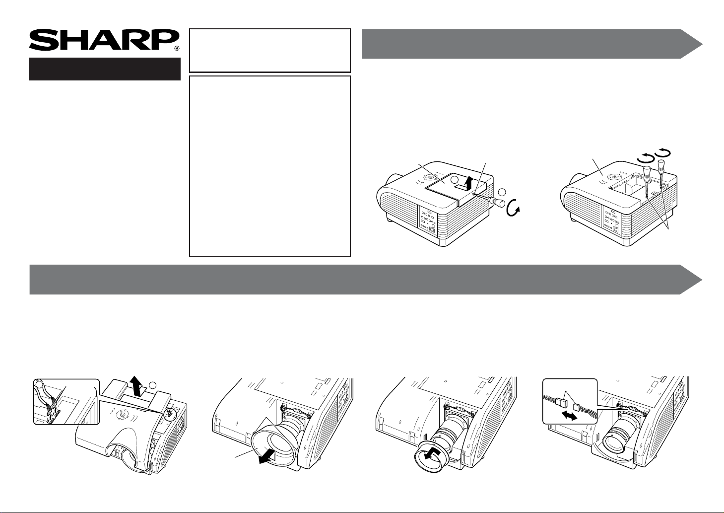
Before replacing the lens, return the lens shift to the position
shown below. (The lens shift is adjusted to the position shown
below when shipped from the factory.)
• V (vertical) shift: Uppermost position
• H (horizontal) shift: Middle position
When replacing the lens, use a commercially available
screwdriver that satisfies all of the conditions indicated below.
• Type 2 Philips head screwdriver
• Length of protruding section: min. 180 mm (10")
• Magnetized
12
Loosen the lamp replacement
screw (
11
1) that fastens the lamp
11
unit cover , and remo ve the lamp
unit cover by sliding in the direction shown by the arrow (
Lamp unit cover
2
22
2).
22
Lamp replacement
screw
1
Remove the mounting screws of
the top cover.
Top cover
Mounting screws
345 6
Unplug the cable connector (
and remove the top cover (
1
Cable
connector
22
2).
22
2
11
1)
11
Release the tabs while pulling up
on the lens cover, and then pull
it out towards y ou.
Tabs
Lens cover
(When the lens being removed is the ANPH30EZ (XG-PH50X standard lens))
Remove the lens ring by turning
in the direction shown by the arrow.
Unplug the cable connector.
Cable connector
Page 2
7
8
9
10
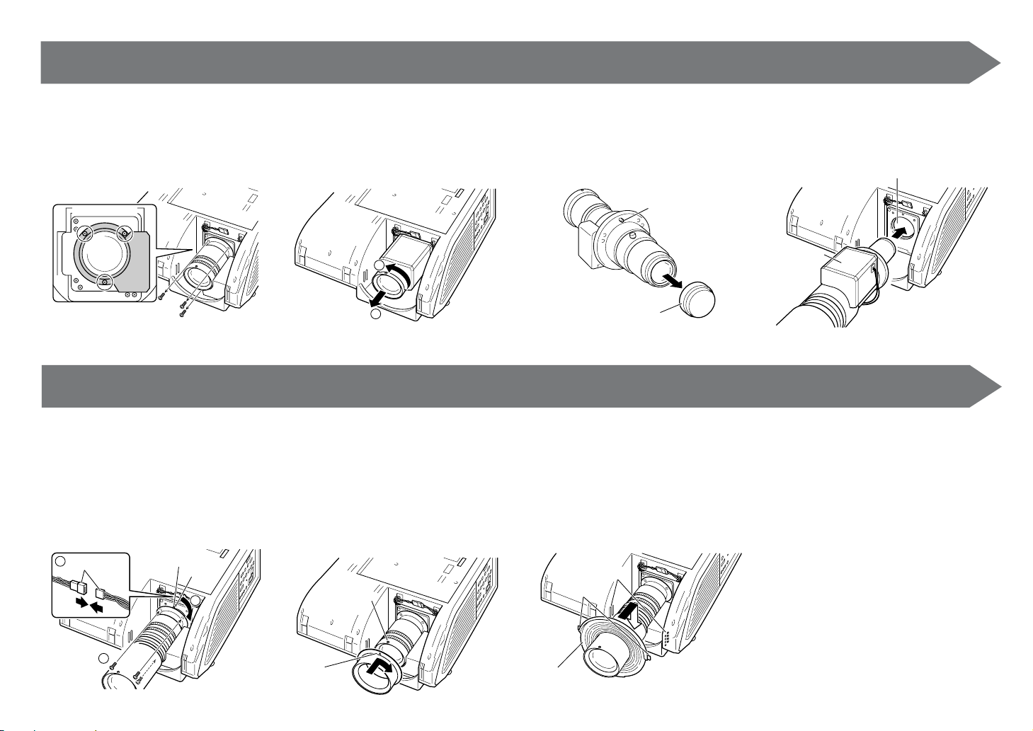
Remove the lens mounting
screws.
Lens mounting screws
Rotate the replacement lens 90
degrees in the direction shown
by the arrow (
11
1), align the posi-
11
tioning pin with the guide hole
22
(
2), tighten the lens mounting
22
screws and then connect the
cable connector (
3
Cable connector
33
3).
33
Positioning pin
Guide
hole
1
Pull out the lens towards you and
then take out the lens (
tating it 90 degrees (
22
2) by ro-
22
11
1) in the di-
11
rection shown by the arrow.
1
2
1211
(When the lens being attached is the ANPH30EZ (XG-PH50X standard lens))
Attach the lens ring.
• Align the a mark on the lens ring with the
positioning pin on the lens (silver pin), insert the lens ring all the way to the back
and then rotate in the direction of the arrow.
Positioning pin
Remove the lens cap (on the
back) from the replacement lens.
• This explanation uses the example of the
AN-PH10EX.
Positioning pin
Lens cap (back)
Insert the replacement lens into
the lens mount with the motor
section facing up.
Motor section
13 14
Attach the lens cover.
• Insert the lens cover while spreading apart
the ring section (made of rubber), and then
attach the tabs to the ribs.
Ribs
Tabs
Connect the cable connector by
following steps 1 through 3, and
then attach the top cover and
lamp unit cover.
• The power of the projector will not come
on unless the lamp unit cover is securely
attached.
Lens mount
2
a
mark
Lens cover
Printed in China
TINS-B760WJZZ
05P01-CH-NM
 Loading...