

Page 1
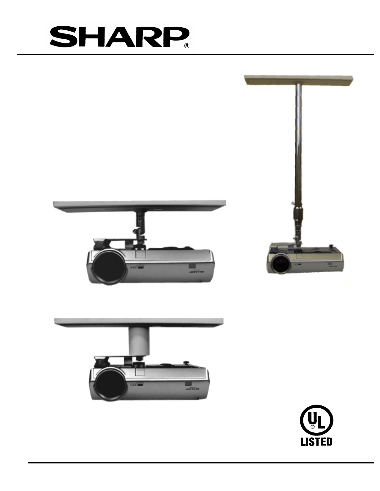
INSTALLATION INSTRUCTIONS FOR
CEIL I NG M O UNTIN G BRACK ET FOR
USE ONLY WITH SHARP
PROJECTOR MODEL
XV-Z2000/DT-400
CEI L I N G MOUNTIN G
BRAC KET AN-CM270
AN-CM270
CEI L I N G MOUNTIN G
BRACKET COMBINED
WITH OPTIONAL
ADJUSTABLE
EXTENSION TUBE
MODEL AN-EP101B
COPYRIGHT ©
2004 SHARP ELECTRONICS CORPORATION
Page 2
INSTALLATION INSTRUCTIONS CEILING BRACKET AN-CM270
C A U T I O N
C A U T I O N
C A U T I O NC A U T I O N
INSTALLATION OF THIS ADJUSTABLE WALL MOUNTING BRACKET
SHOU L D BE P ERF O RMED BY QUALIF IED SERVICE/INSTA LLATION
PERSONNEL FOLLOWING THE INSTALLATION INSTRUCTIONS
IN CL U DED WI T H T H IS BRACKET
THE EXCLAMATION POINT WITHIN AN EQUILATE RAL TRIANGLE
IS INTENDED TO ALERT THE USER TO THE PRESENCE OF IMPORT ANT
OPERATING AND MAINTENANCE (SERVICING) INSTRUCTIONS IN THE
LITERATURE ACCOMPANYING THE APPLIANCE.
IMPORT ANT ! THE INST ALLER SHOULD READ THESE INS TRUCTI ONS TH OROUGHLY
BEFORE BEGINNING THE INSTALLATION AND SHOULD MAKE SURE THAT ALL
T HE WORK IS DONE IN COMPLIANCE WITH NEC AND ALL LOCAL BUILDING
AND SAFETY CODES. SAVE THIS BOOKLET AFTER THE INSTALLATION IS
COMPLETED. THE ACCESSORIES REFERRED TO IN THESE INSTRUCTIONS ARE
INTENDED FOR USE ONLY WITH COMPATIBLE SHARP PROJECTORS. SEE
SHARP PROJECTOR OWNER’S MANUAL OR SHARP DEALER TO DETERMINE
SUITABILITY.
CAUTION: THE BRACKET MOUNTING SCREWS MUST GO DIRECTLY INTO THE
BEAMS. SHEETROCK, LATH AND PLASTER, WILL NOT PROVIDE A
SUFFICIENTLY SECURE SUPPORT.
CAUTION: TO REDUCE THE RISK OF PERSONAL INJURY, USE ONLY THE
COMPONENTS WHICH ARE INCLUDED IN THIS PACKAGE, OR SPECIFIED IN
THESE INSTRUCTIONS.
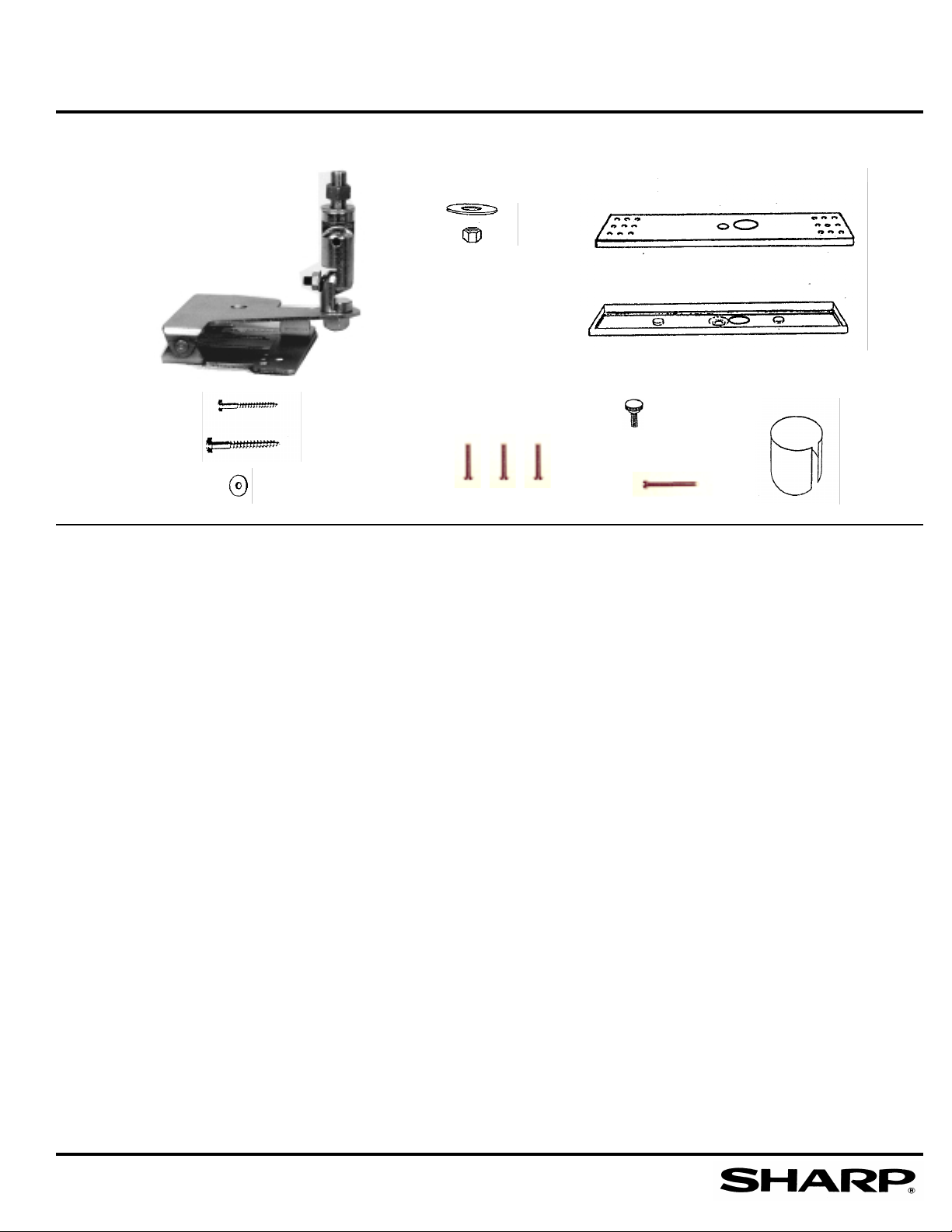
PARTS LIST FOR MODEL AN-CM270 CEILING BRACKET (SEE FIG. 1)
ITEM DESCRIPTION QUANTITY
A. PROJECTOR ATTACHMENT PLATE WHICH INCLUDES THE KNUCKLE
POSITIONING ASSEMBLY. 1
B. LOCKING HEX NUT & WASHER 1
C. STEEL CEILING MOUNTING PLATE 1
D. PLASTIC TRIM FOR CEILING PLATE 1
E. 1/4 X 10 HEX HEAD LAG BOLTS 2-1/2” LONG 6
F. 1/4 X 10 HEX HEAD LAG BOLTS 3” LONG 6
G. 1/4” I.D. WASHERS FOR USE WITH LAG BOLTS 6
H. M4 X 12mm FLAT HEAD MOUNTING SCREWS FOR USE WITH ATTACHMENT PLATE 3
I. M4 X 12mm KNURLED THUMB SCREW 1
J. M4X30mm FLAT HEAD SCREW 1
K. PLASTIC TRIM COLLAR 1
PAGE 2
Page 3
INSTALLATION INSTRUCTIONS CEILING BRACKET AN-CM270
FIGURE 1. I L L U STRA T I ON OF PAR T S FOR CEILIN G BRA C KET
A.
B.
C.
D.
E.
H.
I.
K.
F.
G.
J.
INVERT THE PROJECTOR IMAGE
Please refer to the owners manual for your LCD Projector for detailed instructions of how to electrically
invert the projected image to accommodate its use in the ceiling mounted mode.
LOCATION OF THE CEILING BRACK ET
Please refer to the owner’s manual for your SHARP LCD PROJECTOR for information which will help
you to determine the best location for the placement of the ceiling mounting bracket assembly.
INSTALLATION OF THE CEILING BRACKET
After you have determined the appropriate location for the ceiling bracket, you must locate the exact
location of the ceiling beam s . Mos t s ta n dar d residen tial cons t ruc tion u ses 16 in c hes between cen t e rs
for overhead beams. You can mount the ceiling bracket b y straddling two beams, or you can ins tall the
bracket in line with a single beam.
CAUTION: THE BRACKET MOUNTING SCREWS MUST GO DIRECTLY INTO THE BEAMS.
SHEETROCK, LATH AND PLASTER, WILL NOT PROVIDE A SUFFICIENTLY SECURE
SUPPORT.
STEP 1. INSTALLATION OF THE METAL CEILING BRACKET
A ft e r t h e l o catio n fo r the ceilin g b ra c ket ha s been determined , (see LCD PROJECTOR
Ow ner ’s Manual), make sure to lo ca te beams in t he ceiling.
PAGE 3
Page 4
INSTALLATION INSTRUCTIONS CEILING BRACKET AN-CM270
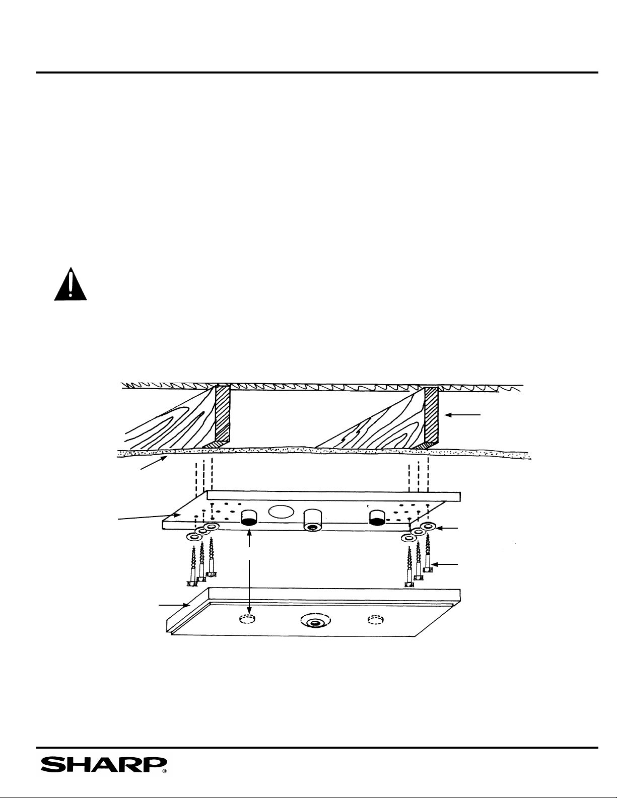
1.1 a. Selec t strad dle beam or s ingle beam installation.
b. Use the ceiling bracket as a template to mark the locat ion where the pilot holes
should be drilled.
c. Drill the pilot holes for the support screws using a 1/8” drill bit into the center of
the beam. (See Figs. 2 and 3).
1.2 Screw the ceiling plate to the beams. Use at least 6 screws and metal washers
supplied with the unit. These screws should be tightened firmly to insure a
v ibration-free support. (See Figs. 2 and 3).
Two sizes of hex head lag bolts are provided. Use shorter screws for sheet rock
surfaces and use the longer screws if the ceiling surface is constructed of a wood
lath and plaster.
CAUTION: THE BRACKET MOUNTING SCREWS MUST GO DIRECTLY INTO
THE BEAMS. SHEETROCK OR LATH AND PLASTER WILL NOT PROVIDE A
SUFFICIENTLY SECURE SUPPORT.
FIGURE 2. ILLUSTRATION OF STRADDLE BEAM CEILING BRACKET INSTALLATION
Sheetrock or lath
and plaster ceiling
Ceiling Mounting
Bracket
Velcro
Plastic Ceiling
Bracket Trim Cover
Washers
1/4 X 10 Lag Bolt
NOTE: THE OUTER ROW OF HOLES ARE 16” BETWEEN CENTERS WHICH IS
THE MOST COMMON BEAM SPACING IN RESIDENTIAL WOOD FRAME
CONSTRUCTION.
Ceiling Beam
PAGE 4
Page 5

INSTALLATION INSTRUCTIONS CEILING BRACKET AN-CM270
FIGURE 3 ILLUSTRATION OF SINGLE BEAM CEILING BRACKET INSTALL A TION
Ceiling Beam
Ceiling Mounting Bracket
Washers
Sheetrock or lath
and plaster ceiling
1/4 x 10 Lag Bolts
DO NOT RUN THE AC POWER CORD THROUGH THE CEILING PLATE AND TRIM COVER
STEP 2. INSTALL THE CEILING MOUNT PLASTIC TRIM
2.1 The Access Hole (See Fig. 4) in the ceiling attachment plate is large enough to accommodate the
molded connectors commonly used the with projector.
2. 2 Audio, Video and other low v oltage connections may be passed through t he access hole in t he
ceiling plate and may also be passed through the plastic trim cover. There is a l abel (See Fig. 4) on
the inside of the plastic trim cover, adjacent to the center mounting bushing.
2.3 Select the contour appropriate for your application and cut out the opening along the line indicated
on the label. Use a very sharp cutting tool.
2.4 Thread the cable through the plastic trim cover. Place the plastic trim cover in place over the
ceiling plate and press the velcro tabs together.
Velcro
FIGURE 4 I NST ALL A T ION OF PLASTIC TRIM ON T HE CEILING BRACKET
Cable Access Hole
Access Hole Template Label
Press Velcro Tabs together
to secure plastic trim cover
in position
PAGE 5
Page 6

INSTALLATION INSTRUCTIONS CEILING BRACKET AN-CM270
STEP 3 DETACH THE POSITIONING ASSEMBLY FROM THE PROJECTOR ATTACHMENT
PLATE.
FIGURE 5
NOTE: PLEASE LOOK OVER THE EXACT MANNER IN WHICH THE
POSITIONING ASSEMBLY AND T HE ATT ACH MENT PLATE GO
TOGETHER SO THAT YOU WILL BE ABLE TO REASSEMBLE THEM
WHEN YOU HANG THE PROJECT OR.
3.1 Using 9 / 16 ” box wrench, remove the nut from the lower knuckle
(vert ical position) and slide t he center an d upper k n u ckle assembly apar t
from t he bottom knuck le w h ic h is part o f the
attachment plate. (See Fig. 5)
SPECIAL NOTE TO INSTALLERS: In s ome instances the relationship of
the locat ion o f t he projec ti on screen to t he exact po siti on o f t he ceiling
moun t in g b racke t m akes it desirable t o have the center line of t he lens at
the center of the mounting bracket. I f you find it necessary to have the
lens at t he cen ter line o f t h e mo un t , r emo ve the lo w e r element of the
positioning knuck le f rom its original posit ion and re-mount it in the D
shaped h o le i n the mounti n g p late lo c ated i n t he area over t he lens. Th is
will align the centerline of the lens with the center of the mounting
bracket. T he posit ioning knuc k le assembly can easily compensate f or the
slight loss of sta ti c balance of t he m ounted projector.
STEP 4 INSTALLA TION OF THE PROJECTOR ATT ACH MENT PLATE
4. 1 Place the attachment plate over t he bott om o f the projector (See Fig. 6)
and al ign the holes of the plate with the threaded fittings on the projector case.
4. 2 Install the three M 4 x 12 mm long screws provided. Fasten these securely but
DO NOT overtighten. (See Fig. 7)
4. 3 Install the longer, M4 x 3 0 mm flat head scre w in to t he indicated hole. (I t goes
into the recessed fitting in th e plastic housing).
FIGURE 6.
FIGURE 7.
M4x12mm mounting
screw
PAGE 6
M4x30mm screw
M4x12mm screw
Page 7

INSTALLATION INSTRUCTIONS CEILING BRACKET AN-CM270
4. 3 Fold the at tachm ent plate down on i t s hinge. See Fig. 8
4. 4 Install the M4 knurled thumb screw b y hand. See Fig. 8. DO NOT USE TOOLS TO
TIGHTEN THIS SCREW.
FIGURE 8
M4 Knurled Thumb Scre w
RE MINDE R : MAKE SURE TO ALLOW SUFFICIENT SLACK IN THE WIRING TO PERMIT THE
PROJECTOR TO SWING DOWN ON THE HINGE TO ALLOW EASY SERVICING OF THE FILTER
AN D THE L AMP A SSEMBLY.
STEP 5 ATTACH THE POSITIONING ASSEMBLY TO THE CEILING PLATE
FIGURE 9
Ceiling Trim Cover Cable Access Hole
Washer
Locking Hex Nut
Upper Knuckle
Assembly
IF Y OU INTEN D TO RUN AUDI O OR VIDEO CABLES THROUGH THE CEILING PLA TE
PROCEED WITH STEP 5.1 AND 5.2, OTHERWISE PROCEED TO STEP 5.3:
5.1 Cut opening in t he ceiling plate trim co ver as indicated on the label inside cover near
the center b ushing.
5.2 Thread cables through the plastic trim cover.
DO NOT RUN THE AC POWER CORD INSIDE THE PLASTIC TRIM COVER.
ALL WIRING MUST COMPLY WITH THE NEC AND ALL LOCAL BUILDING,
ELECTRIC, AND SAFETY CODES.
PAGE 7
Page 8

INSTALLATION INSTRUCTIONS CEILING BRACKET AN-CM270
5.3 Place the plastic trim cover in position over the ceiling plate and press the Velcro
tabs together.
5.4 After completing step #5.3, screw the longer shaft with the locking nut and washer
into the center threaded bush ing on the ceiling plate as far as it will g o. (See Fig. 9)
5.5 Tighten the locking nut against the ceiling plate using a 3/4” open end wrench or an
adjustable c rescent wrench.
5.6 Tighten the locking nut on the upper knuckle using a 9/16” box wrench.
DO NOT RUN THE AC POWER CORD INSIDE THE PLASTIC TRIM COVER.
ALL WIRING M UST COMPLY WITH THE NEC AND ALL LOCAL BUILDING,
ELECTRIC, AND SAFETY CODES.
STEP 6 HANGING THE PROJECTOR FROM POSITIONING ASSEMBLY
6.1 Raise the projector with the mounting plate attached and slide the fitting (See Fig. 10)
o ver the support stud on the hanging position.
6. 2 Replace the locking nut (removed in step 3 .1). Using the 9/16” box wrench run the nut
up but do not ti ght en all the way.
FIGURE 10
STEP 7 A I M THE PROJECTOR
7.1 A fter t he pro ject or has been property wi red, t u rn i t o n and loosen the posi tio ning
assembly adjustment nuts just enough so that you can move the p r ojector fairly easily.
(See Fig. 11) DO NOT COMPLETELY LOOSEN THE NUTS.
7. 2 Set t he Horizontal Centering by loosening the ceiling locking nut, mo ve t he projector to
center the image and tighten the nut. (Use 3/4” open end wrench).
7.3 Set the vertical centering and tighten the lowe r positioning adjustment nut.
(See Fig. 11)
7. 4 Set the Horizontal til t and tighten t he upper positioning adjustmen t nut . (See Fig. 1 1)
PAGE 8
Page 9

INSTALLATION INSTRUCTIONS CEILING BRACKET AN-CM270
FIGURE 1 1 DETAIL OF POSITIONING ASSEMBLY
CEILING PLATE
PLASTIC CEILING PLATE
TRIM CO VER
LOCKING NUT AND HORIZONTAL POSITION ADJUSTMENT
HORIZONTAL T ILT AD J U STMENT
VERTICAL POSITION ADJUSTMENT
STEP 8 INST ALL THE PLASTIC TRIM COLLAR
8.1 T he plastic t r im co lla r m a y be used as a c osm e tic c o n ceal ment of t h e pos i t i o n in g adj us t m e n t kn uc k l e
assembl y and t he audio and video signal cables.
8. 2 The sli t side of t he collar enables the installer to spread the collar enough t o place it over the adjustmen t
k n uc k le . It will c urve back by i t s o wn spr ing ac tion t o wrap around itself enough to c l ose the gap.
(See Fig. 12)
8. 3 If t he project or is hung a t a sharp angle, you m a y t r im the collar f or a better fit . (See Fig. 13)
FIGURE 12 FIGURE 13
DO NOT RUN THE A C POWER CORD INSIDE THE PLASTIC TRIM COLLAR. ALL
WIRING MUST COMPLY WITH T HE NEC AND ALL LOCAL BUILDING, ELECTRIC AND
SAFETY CODES.
NOTE: IN THE EVENT YOU WISH TO USE THE SHARP ADJUSTABLE EXTENSION
ACCESSORY IN CONJUNCTION WITH THE CEILING MOUNTING BRACKET, PLEASE
REFER TO THE INSTALLATION INSTRUCTION MANUAL INCLUDED IN THE
EX TEN S I ON TUBE PACKAGE .
PAGE 9
Page 10

INSTALLATION INSTRUCTIONS CEILING BRACKET AN-CM270
P ROCEDURE FOR S ERVICI N G LAM P HOU SI N G O R AI R FILTER:
A. Remove t he knurled t humb screw. See Fig. 14. The projector will swing down on the
hinge of t he moun tin g bracket. The bot t o m of t he projector wi l l now be in a position to
permit servicing the lamp assembly.
B. Proceed to service th e air filter or the lamp assembly. Follow the appropriate
instruc tions in your projector ow ner’s manual.
FIGURE 14 . H I N GED
ATTACHME NT PLA TE
MAKES SERVICING EASIER
Knurled thumb scre w
C. After completing the service procedure swing the projector back up and re-install the
knurled thumb screw.
NOTE: HINGED A TT A CH MENT PLATE ALLOWS PROJECTOR TO DROP DOWN FOR EASY
ACCESS TO FILTER AND LAMP HOUSING. SEE PROJECTOR OWNER’S MA NUAL FOR
DETAILS OF FILTER OR LAMP REPLACEMENT PROCEDURES.
PAGE 10
Page 11

INSTALLATION INSTRUCTIONS CEILING BRACKET AN-CM270
DIMENSIONS AND MEASURE MENTS OF COMPONENTS FOR
SHARP M OU NTING BRACKET AN- CM70
CEI L I N G PL ATE 4” WI D E X 18” LO N G
DISTANCE BETWEEN SETS OF MOUNTING HOLES: 1st SET 12 ” , 2nd SET 14”, 3rd SET 16”
ADDI TION AL POSSIBLE COMBINATIONS OF MOUNTING HOLE DISTANCE 13” & 15”
THREAD SIZE OF SWIVEL SHAFT & C EILING PLATE BUS HING 1/2” X 20
15
”
VEL-
CABLE ACCESS HOLE
SPECIFICATIONS SUBJECT TO CHANGE WITHOUT NOTICE
12”
14”
16”
18”
VEL-
CENTER BUSHIN G 7/8 ” DEEP
1/2X20 THREADED HOLE
4”
ATTACHMENT PLATE WITH POSITIONING ASS EMBLY:
SPECIFICATIONS SUBJECT TO CHANGE WITHOUT NOTICE
A. From ceiling to in verted bottom of projector: 5 1/2”
B. Length of position adj ustment knuckle assembly: 3 1/2”
C. Lens offset from center of lens to center of mounting bushing: 3”
D. Ceiling to center of lens: 7”
E. Ceiling to top of inverted projector: 8 7/8”
F. M ounting screws M4 X 12 & 30 mm long metric flat head phillips.
PAGE 11
Page 12

INSTALLATION INSTRUCTIONS CEILING BRACKET AN-CM270
ONE YEAR LIMITED WARRANTY
SHARP Electronics Corporation warrants to the first end use purchaser, that this SHARP brand
product (the “Product”), when shipped in its original container, will be free from defective
workmanship and materials, and agrees that it will, at its option, either repair the defect or replace
the defective product or part thereof at no charge to the purchaser for parts or for labor, excluding
costs of removal and/or installation, for one year from date of purchase.
This warranty does not apply to any appearance items of the Product nor to any Product the
exterior of which has been damaged or defaced, which has been subject to misuse, abnormal
service or handling, or which has been altered or modified in design or construction.
In order to avail the purchaser of his/her rights under this limited warranty, the purchaser should
carry in or ship the Product prepaid and insured, including proof of purchase, to:
SHARP Electronics, c/o AVDEX, 115 Henry Street, Freeport, NY 11520.
The limited warranty described above is in addition to whatever implied warranties may be
granted to purchasers by law. To the extent permitted by applicable law ALL IMPLIED
WARRANTIES INCLUDING THE WARRANTIES OF MERCHANTABIL ITY AND FITNESS FOR
USE ARE LIMITED TO THE PERIOD(S) FROM THE DATE OF PURCHASE SET FORTH
ABOVE. Some states do not allow limitations on how long an implied warranty lasts, so the
above limitation may not apply to you.
Neither the sales personnel of the seller nor any other person is authorized to make any
warranties other than those described above, or to extend the duration of any warranties beyond
the time period described above on behalf of SHARP.
The warranties described above shall be the sole and exclusive warranties granted by SHARP
and shall be the sole and exclusive remedy available to the purchaser. Correction of defects, in
the manner and for the period of time described herein, shall constitute fulfillment of all liabilities
and responsibilities of SHARP to the purchaser with respect to the Product, and shall constitute
full satisfaction of all claims, whether based on contract, negligence , strict liab ility or otherwise.
In no event shall SHARP be liable, or in any way responsible, for any damages or defects in the
Product which were caused by repairs or attempted repairs performed by anyone other than
SHARP. Nor shall SHARP be liable or in any way responsible for incidental or consequential
economic or property damage. Some states do not allow the exclusion of incidental or
consequential damages, so the above exclusion may not apply to you.
THE WARRANTY GIVES YOU SPECIFIC LEGAL RIGHTS. YOU MAY ALSO HAVE OTHER
RIGHTS WHI CH VARY FROM STATE TO ST ATE.
Specifications are subject to change without notice.
SHARP ELECTRONICS CORPORATION, SHARP PLAZA, MAHWAH, NJ 07430
COPYRIGHT ©
PAGE 12
2004 SHARP ELECTRONICS CORPORATION
 Loading...