

Page 1
AN-C27MZ
Tele-zoom lens for LCD projector
Tele-zoomobjektiv für LCD-Projektor
Téléobjectif-zoom pour projecteur LCD
Objetivo telefoto-zoom para proyector LCD
English
Deutsch
Français
Español
INSTALLATION MANUAL
INSTALLATIONSHANDBUCH
MANUEL D’INSTALLATION
MANUAL DE INSTALACIÓN
Page 2
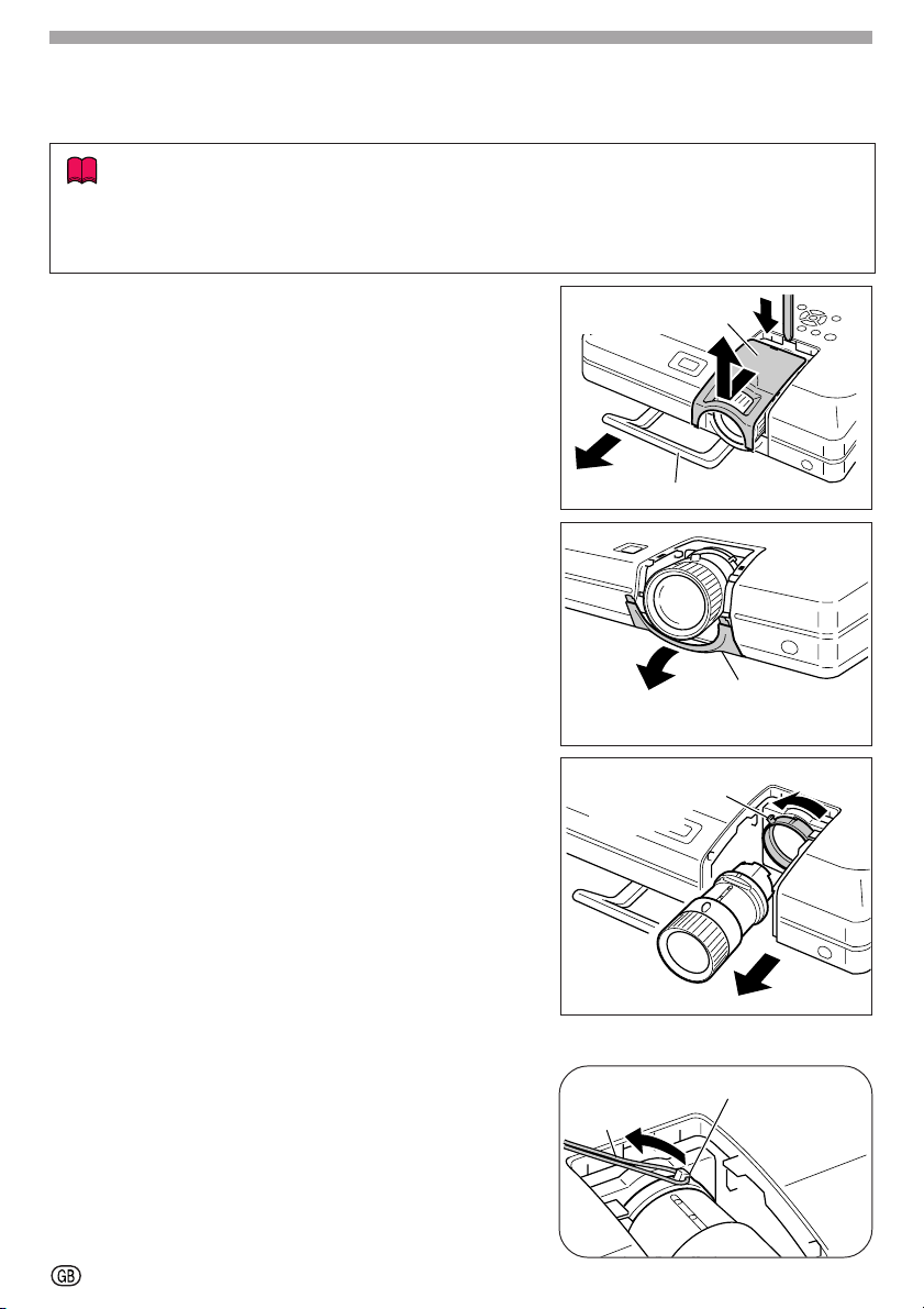
Changing the Lens
Lens fastener
catch tab
Lock release
strap
When changing the lens, use the supplied lens cover stick.
Info
• Before changing the lens turn off the power to the projector and remove the power cord
from the wall outlet.
• Do not attempt to change the lens while the projector is mounted on the ceiling.
1 Pull out the carrying handle.
2 Use the tip of the supplied lens cover stick
to push down on the groove on top of the
upper half of lens cover while pulling forward to remove it with your hand.
3 To remove the bottom half of the lens cover,
pull it down and towards you.
4 To remove the lens, hold it in one hand, to
keep it from dropping, while you turn the lens
fastener catch tab in the direction of the arrows in the illustration with your other hand.
• If the lens fastener ring is stiff, attach the supplied lock release strap to the catch tab on the
lens fastener ring and pull the strap to turn it.
Upper half of the
lens cover
1
Carrying handle
3
Lower half of
the lens cover
Lens fastener
catch tab
2
4
5 Remove the lens.
-1
5
Procedure for loosening the stiff
lens fastener ring
Page 3

6 First insert tabs
8
AA
holes
A of the projector, then push tabs
AA
into tab holes
aa
a of the lens cover into tab
aa
BB
B until it clicks into place.
BB
7 Push in the carrying handle.
8 Remove the cap from the back of the lens.
bb
b
bb
7
Tabs b
Tab holes B
6
Tabs a
Tab holes
A
9 Make sure that the two grooves on the lens
fastener ring are facing upward.
10 Ensure that the two grooves on the lens
mount face upward and the pin of lens insertion area is inserted into the hole of the
lens mount as you push the lens into the
projector.
• Make sure the lens is pushed into the projector interior firmly.
11 Turn the lens fastener catch tab in the direc-
tion of the arrows in the illustration until it
stops.
• Be careful not to turn the lens fastener ring
too tight, as the lens fastener ring will be stiff
the next time the lens is changed.
12 After inserting the upper half of the lens
cover tabs into the projector tab holes, slide
the lens cover towards the projector until it
clicks into place.
• If the upper half of the lens cover is not secured to the projector, you will not be able to
turn the power on.
Grooves
Lens
mount
12
Lens fastener
ring
Hole
11
9
Pin
10
Tabs
Tab holes
-2
Page 4
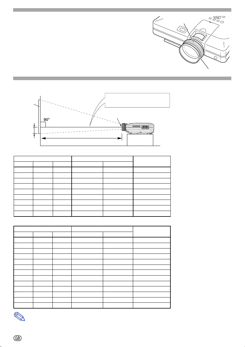
Adjust the picture size and focus
Zoom ring
Turn the zoom ring to adjust picture size.
Turn the focus ring to adjust the focus.
Picture size and projection distance chart
Base line:
Screen
H
L : Projection distance
NORMAL Mode (4:3)
Picture (Screen) size Projection distance [L]
Diag. [χ] WidthHeight
300" (762 cm) 240" (609.6 cm)
250" (635 cm) 200" (508 cm) 150" (381 cm)
200" (508 cm) 160" (406.4 cm)
150" (381 cm)
100" (254 cm) 80" (203.2 cm)
84" (213.3 cm) 67" (170.1 cm) 50" (127 cm)
72" (182.8 cm) 58" (147.3 cm)
60" (152.4 cm) 48" (121.9 cm) 36" (91.4 cm)
40" (101.6 cm) 32" (81.2 cm) 24" (60.9 cm)
120" (304.8 cm)
180" (457.2 cm)
120" (304.8 cm)
90" (228.6 cm)
60" (152.4 cm)
43" (109.2 cm)
Maximum [L1] Minimum [L2]
85' 2"
(26.0 m)
70' 11"
(21.6 m)
56' 8"
(17.3 m)
42' 4"
(12.9 m)
1"28'
6"23'
1"20'
8"16'
11'
STRETCH Mode (16:9)
Picture (Screen) size Projection distance [L]
Diag. [χ] Width
300" (762 cm) 261" (662.9 cm)
250" (635 cm) 218" (553.7 cm)
225" (571.5 cm)
200" (508 cm) 174" (441.9 cm) 98" (248.9 cm)
150" (381 cm) 131" (332.7 cm) 74" (188 cm)
133" (337.8 cm)
106" (269.2 cm)
100" (254 cm) 87" (220.9 cm)
92" (233.6 cm) 80" (203.2 cm)
84" (213.3 cm) 73" (185.4 cm)
72" (182.8 cm) 63" (160 cm) 35" (88.9 cm)
60" (152.4 cm) 52" (132 cm) 29" (73.6 cm)
40" (101.6 cm) 35" (88.9 cm) 20" (50.8 cm)
196" (497.8 cm)
116" (294.6 cm) 65" (165.1 cm)
92" (233.6 cm) 52" (132 cm)
eight
H
147" (373.4 cm)
123" (312.4 cm)
110" (279.4 cm)
49" (124.4 cm)
45" (114.3 cm)
41" (104.1 cm)
92' 8"
77' 2"
69' 5"
61' 8"
46' 2"
40' 10"
32' 6"
30' 7"
28' 1"
25' 7"
21' 11"
18' 2"
12'
Maximum [L1] Minimum [L2]
(28.3 m)
(23.5 m)
(21.2 m)
(18.8 m)
(14.1 m)
(12.5 m)
Horizontal line passing through
the lens center
Lens center
(16.5 m)
54' 2"
(13.7 m)
45' 1"
(11.0 m)
36'
(8.2 m)
10"26'
(5.4 m)
(8.6 m)
(7.2 m)
(6.1 m)
(5.1 m)
(3.4 m)
(9.9 m)
(9.3 m)
(8.6 m)
(7.8 m)
(6.7 m)
(5.5 m)
(3.7 m)
10"14'
6' 10"
59' 1"
49'
44' 3"
39' 3"
29' 4"
25'
11"
20'
19'
17'
10"
16'
13'
10"
11'
7' 6"
9"17'
8"12'
6"10'
2"
7"
5"
2"
5"
(4.5 m)
(3.9 m)
(3.2 m)
(2.1 m)
(18.0 m)
(15.0 m)
(13.5 m)
(12.0 m)
(8.9 m)
(7.9 m)
(6.3 m)
(5.9 m)
(5.4 m)
(4.9 m)
(4.2 m)
(3.5 m)
(2.3 m)
Distance from the lens center
to the bottom of the image [H]
17
63 / 64"
61 / 64"
31 / 32"
8
31 / 32"
63 / 64"
5
3 / 64"
5
4
21 / 64"
37 / 64"
3
2
13 / 32"
"
11 / 64"
47 / 64"
11 / 32"
33 / 64"
13 / 64"
49 / 64"
21 / 32"
17 / 32"
27 / 64"
–63 / 64"
–43 / 64"
7 / 32"
(45.7 cm)
(38.0 cm)
(30.4 cm)
(22.8 cm)
(15.2 cm)
(12.8 cm)
(11.0 cm)
(9.1 cm)
(6.1 cm)
(–12.7 cm)
(–10.6 cm)
(–9.5 cm)
(–8.5 cm)
(–6.4 cm)
(–5.6 cm)
(–4.5 cm)
(–4.2 cm)
(–3.9 cm)
(–3.6 cm)
(–3.1 cm)
(–2.5 cm)
(–1.7 cm)
14
11
Distance from the lens center
to the bottom of the image [H]
–5
–4
–3
–3
–2
–2
–1
–1
–1
–1
–1
The formula for picture size and
projection distance
χ
: Picture size (diag.) (in)
[Feet, inches]
L1 (ft)
L2 (ft) =
H (in) =
[m, cm]
L1 (m)
L2 (m) =
H (cm) =
The formula for picture size and
projection distance
χ
: Picture size (diag.) (in)
[Feet, inches]
L1 (ft)
L2 (ft) =
H (in) =
[m, cm]
L1 (m) =
L2 (m) =
H (cm) =
Focus ring
(0.087χ – 0.1353) / 0.3048
=
(0.0555χ – 0.1377) / 0.3048
(0.1522χ – 0.002) / 2.54
=
0.087χ – 0.1353
0.0555χ – 0.1377
0.1522χ – 0.002
=
(0.0946χ – 0.1356) / 0.3048
(0.0605χ – 0.1377) / 0.3048
(–0.0424χ + 0.0013) / 2.54
0.0946χ – 0.1356
0.0605χ – 0.1377
–0.0424χ + 0.0013
Note
• There is error of ±3% in the formula above.
• Values with a minus(–) sign indicate the distance of the lens center below the bottom of screen.
-3
Page 5

Handling Precautions
● Do not disassemble this lens.
Please refer to your authorized dealer for any maintenance and inspections requiring an open
cabinet.
● Except for the lens fastener catch tab, touching any other internal part could cause
personal injury or machine malfunction.
● Do not touch any glass or protruding part of the lens. This may cause personal injury
and reduced performance of the projector.
● When maintaining the projector the following points should be noted.
• When cleaning the lens be sure to use a commercial air blower or lens cleaning paper (used
in cleaning glasses and cameras).
• The surface of the lens is very delicate. Do not allow hard objects to bump or rub against it.
Caution
●
Be sure not to attach this lens to the projector when storing or carrying the projector. This
may cause damage to them.
Supplied Accessories
• 1 lens cover stick • 1 lock release strap
• 2 lens caps (for the front and the back) • Installation Manual (this manual)
Projector and Lens Dimensions
329 - 334 (1261/64" - 135/32")
Unit : mm (inch)
80
Specifications
Product type Tele-zoom lens for LCD projector
Model AN-C27MZ
Type of lens Zoom lens
Picture size (diagonal) 40'' to 300''
Focal length 53.8 to 82.9 mm (21/8'' to 31/4'')
F no. 2.0 to 2.8
Throw ratio 1:2.7 to 4.3
Weight Approx. 710g (1.57 lbs)
Dimensions ø80 × 164 mm (6
29
/64'')
-4
Page 6

Memo
Page 7

SHARP CORPORATION
Printed in Japan
Gedrukt in Japan
Imprimé au Japon
Improso en Japón
03P02-JM
 Loading...