

Page 1

English
Deutsch
Français
AN-C18MZ
Tele-zoom lens for LCD projector
Tele-Zoomobjektiv für LCD-Projektor
Téléobjectif-zoom pour projecteur LCD
Objetivo telefoto-zoom para proyector LCD
INSTALLATION MANUAL
INSTALLATIONSHANDBUCH
MANUEL D’INSTALLATION
MANUAL DE INSTALACIÓN
Español
Page 2
Changing the Lens
Info
• Before changing the lens, turn off the power of the projector and remove the power cord
from the wall outlet.
• Do not attempt to change the lens while the projector is mounted on the ceiling.
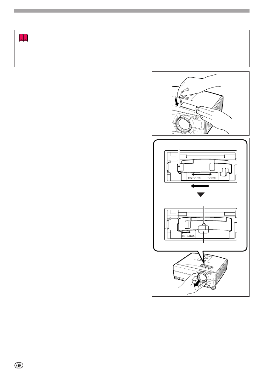
1 Remove the lens housing cover by us-
ing the supplied lens housing cover removal tool to push down on the groove
on the lens housing cover.
• Hold down the lens housing cover with your
hand to prevent it from flying out.
2 Slide the lens fastener catch tab in the
direction of “UNLOCK” while holding the
lens to prevent it from falling out.
• Slide the lens fastener catch tab until the
window located beside “LOCK” comes to
the top. Look inside the window to make
sure that the two grooves on the lens
fastener ring are facing up.
3 Remove the lens by pulling it straight out.
4 Remove the protection cap from the back
of the new lens.
Lens fastener catch tab
Two grooves
Window
-1
Page 3

5 Insert the lens into the projector.
• As you insert the lens, look inside the window to make sure that the pin is inserted
into the hole of the lens mount.
Pin
Lens
mount
6 Slide the lens fastener catch tab in the
direction of “LOCK” until it stops.
• Be careful not to rotate the lens fastener
ring too tight, as the lens fastener ring will
be difficult to loosen the next time the lens
is changed.
7 Replace the lens housing cover.
• If the lens housing cover is not secured to
the projector, you will not be able to turn
the power on.
Lens fastener catch tab
-2
Page 4

Picture size and projection distance chart
Screen
Base line:
Horizontal line passing through the lens center
Lens center
H
L : Projection distance
NORMAL Mode (4:3)
Picture (Screen) size Projection distance [L]
Diag. [χ] Width Height Minimum [L1] Maximum [L2]
250'' (635 cm) 508 cm (200'') 381 cm (150'') 11.3 m (37' 2") 14.4 m (47' 1") –38 cm (–15")
200'' (508 cm) 406 cm (160'') 305 cm (120'') 9.1 m (29' 9") 11.5 m (37' 8") –30 cm (–12")
150'' (381 cm) 305 cm (120'') 229 cm (90'') 6.8 m (22' 3") 8.6 m (28' 3") –23 cm (–9")
100'' (254 cm) 203 cm (80'') 152 cm (60'') 4.5 m (14' 10") 5.7 m (18' 10") –15 cm (–6")
84'' (213 cm) 171 cm (67'') 128 cm (50'') 3.8 m (12' 6") 4.8 m (15' 10") –13 cm (–5
80'' (203 cm) 163 cm (64'') 122 cm (48'') 3.6 m (11' 11") 4.6 m (15' 1") –12 cm (–4
72'' (183 cm) 146 cm (58'') 110 cm (43'') 3.3 m (10' 8") 4.1 m (13' 7") –11 cm (–4
60'' (152 cm) 122 cm (48'') 91 cm (36'') 2.7 m (8' 11") 3.4 m (11' 4") –9 cm (–3
40'' (102 cm) 81 cm (32'') 61 cm (24'') 1.8 m (5' 11") 2.3 m (7' 6") –6 cm (–2
χ
: Picture size (diag.) (in/cm)
L : Projection distance (m/ft)
L1 : Minimum projection distance (m/ft)
L2 : Maximum projection distance (m/ft)
Distance from the lens center to the bottom of the image (cm/in)
H :
Distance from the lens center
to the bottom of the image [H]
3
/64")
51
/64")
5
/16")
19
/32")
13
/32")
The formula for picture size and projection distance
[m/cm]
L1 (m) = 0.04529
L2 (m) = 0.05745
H (cm) = –0.1524
[ft/in]
χ
L1 (ft) = 0.04529 χ / 0.3048
χ
L2 (ft) = 0.05745 χ / 0.3048
χ
H (in) = –0.1524 χ / 2.54
STRETCH Mode (16:9)
Picture (Screen) size Projection distance [L]
Diag. [χ] Width Height Minimum [L1] Maximum [L2]
225'' (572 cm) 498 cm (196'') 280 cm (110'') 11.1 m (36' 5") 14.1 m (46' 2") 9 cm (3 43/64") ±47 cm (±18 25/64")
200'' (508 cm) 443 cm (174'') 249 cm (98'') 9.9 m (32' 5") 12.5 m (41' 1") 8 cm (3
150'' (381 cm) 332 cm (131'') 187 cm (74'') 7.4 m (24' 3") 9.4 m (30' 10") 6 cm (2
133'' (338 cm) 294 cm (116'') 166 cm (65'') 6.6 m (21' 6") 8.3 m (27' 4") 6 cm (2
106'' (269 cm) 235 cm (92'') 132 cm (52'') 5.2 m (17' 2") 6.6 m (21' 9") 4 cm (1
100'' (254 cm) 221 cm (87'') 125 cm (49'') 4.9 m (16' 2") 6.3 m (20' 6") 4 cm (1
92'' (234 cm) 204 cm (80'') 115 cm (45'') 4.5 m (14' 11") 5.8 m (18' 11") 4 cm (1
84'' (213 cm) 186 cm (73'') 105 cm (41'') 4.1 m (13' 7") 5.3 m (17' 3") 3 cm (1
80'' (203 cm) 177 cm (70'') 100 cm (39'') 3.9 m (12' 11") 5.0 m (16' 5") 3 cm (1
72'' (183 cm) 159 cm (63'') 90 cm (35'') 3.6 m (11' 8") 4.5 m (14' 9") 3 cm (1
60'' (152 cm) 133 cm (52'') 75 cm (29'') 3.0 m (9' 9") 3.8 m (12' 4") 2 cm (
40'' (102 cm) 89 cm (35'') 50 cm (20'') 2.0 m (6' 6") 2.5 m (8' 3") 2 cm (
χ
: Picture size (diag.) (in/cm)
L : Projection distance (m/ft)
L1 : Minimum projection distance (m/ft)
L2 : Maximum projection distance (m/ft)
Distance from the lens center to the bottom of the image (cm/in)
H :
S : Adjustable range of image position (cm/in)
Distance from the lens center
to the bottom of the image [H]
63
21
The formula for picture size and projection distance
[m/cm]
L1 (m) = 0.04934
L2 (m) = 0.06259
H (cm) = 0.04151
S (cm) = ±0.20754
χ
χ
χ
χ
Adjustable range of
image position [S]
17
/64") ±42 cm (±16 11/32")
29
/64") ±31 cm (±12 1/4")
11
/64") ±28 cm (±10 7/8")
47
/64") ±22 cm (±8 21/32")
41
/64") ±21 cm (±8 11/64")
1
/2") ±19 cm (±7 33/64")
3
/8") ±17 cm (±6 55/64")
5
/16") ±17 cm (±6 17/32")
11
/64") ±15 cm (±5 57/64")
/64") ±12 cm (±4 29/32")
/32") ±8 cm (±3 17/64")
[ft/in]
L1 (ft) = 0.04934 χ / 0.3048
L2 (ft) = 0.06259 χ / 0.3048
H (in) = 0.04151 χ / 2.54
S (in)= ±0.20754 χ / 2.54
Note
• Allow a margin of error in the values in the diagrams above.
• When the distance from the lens center to the bottom of the image [H] is a negative number,
this indicates that the bottom of the image is below the lens center.
-3
Page 5
Handling Precautions
● Do not disassemble this lens.
Please refer to your authorized dealer for any maintenance and inspections requiring an open cabinet.
● Touching any internal parts other than the lens fastener catch tab can cause personal
injury or machine malfunction.
● Do not touch the glass or any protruding part of the lens. This may cause personal
injury and reduced performance of the projector.
● When maintaining the projector the following points should be noted.
• When cleaning the lens, be sure to use a commercial air blower or lens cleaning paper
(used in cleaning glasses and cameras).
• The surface of the lens is very fragile. Do not allow hard objects to bump or rub against it.
Caution
●
Be sure not to attach this lens to the projector when storing or carrying the projector. This
may cause damage to the lens and/or projector.
Supplied Accessories
• 1 lens housing cover removal tool • 1 front lens cap
• 1 protection cap for the back of the lens • Installation Manual (this manual)
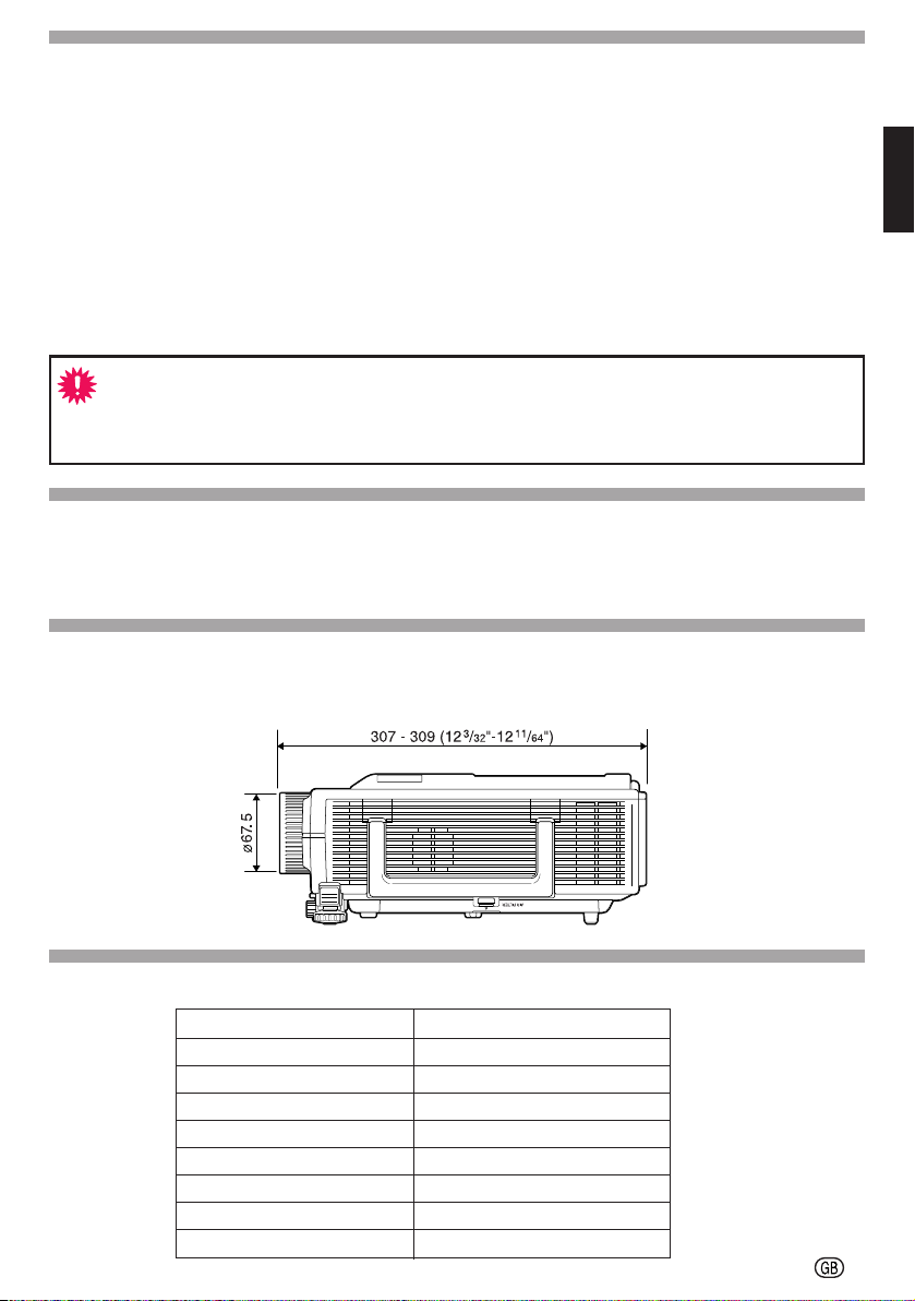
Projector and Lens Dimensions
(When AN-C18MZ is installed)
Specifications
Product type
Model
Type of lens
Picture size (diagonal)
Focal length
F no.
Throw ratio
Weight
Dimensions
Unit : mm (inch)
Tele-zoom lens
AN-C18MZ
Zoom lens
40'' to 250''
36.5 to 46.3 mm
1.7 to 2.2
1:2.2 to 2.8
Approx. 410 g (0.9 lbs)
ø67.5 x 124 mm
-4
Page 6
Objektiv austauschen
Info
• Schalten Sie die Stromversorgung des Projektors aus und ziehen Sie das Netzkabel von
der Netzsteckdose ab, bevor Sie das Objektiv austauschen.
• Versuchen Sie nicht, das Objektiv auszutauschen, wenn der Projektor noch an der Decke
installiert ist.
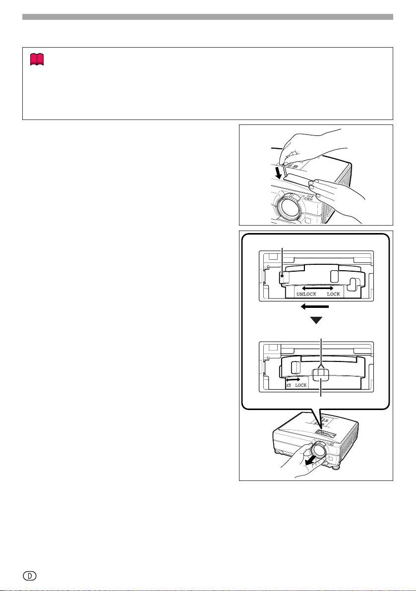
1
Öffnen Sie die Objektivabdeckung mit
dem beiliegenden Objektivabdeckungsstab, indem Sie diesen in die Nut an der
Objektivabdeckung drücken.
• Halten Sie die Objektivabdeckung dabei
mit der Hand zurück, damit sie nicht
herausspringt.
2
Halten Sie das Objektiv zum Abnehmen mit
einer Hand fest, damit es nicht herunterfällt, und schieben Sie die Objektivbefestigungsnase in Richtung „UNLOCK“.
• Drehen Sie die Objektivbefestigungsnase
so weit, dass das neben „LOCK“
befindliche Fenster nach oben gewendet
ist. Vergewissern Sie sich durch das
Fenster, dass die beiden Nuten am
Objektivbefestigungsring oben liegen.
Objektivbefestigungsnase
Zwei Nuten
3 Entfernen Sie das Objektiv, indem Sie es
geradlinig herausziehen.
4 Entfernen Sie die Schutzkappe von der
Rückseite des neuen Objektivs.
-1
Fenster
Page 7

5 Setzen Sie das Objektiv in den Projektor
ein.
• Kontrollieren Sie sich beim Einsetzen des
Objektivs mit einem Blick in das Fenster,
dass der Stift korrekt in das Loch in der
Objektivhalterung eingreift.
Stift
Objektivhalterung
6 Schieben Sie den Objektivbefestigung-
snase bis zum Anschlag in Richtung
„LOCK“.
• Achten Sie dabei darauf, dass der
Objektivbefestigungsring nicht zu fest
aufgedreht wird, da er sich sonst beim
nächsten Objektivwechsel schwer lösen
lässt.
7 Bringen Sie die Objektivabdeckung
wieder an.
• Wenn die Objektivabdeckung nicht fest am
Projektor befestigt ist, können Sie den
Projektor nicht einschalten.
Objektivbefestigungsnase
-2
Page 8

Tabelle für Bildformat und Projektionsentfernung
Bildwand
Grundlinie:
Horizontale Linie, die die Objektivmitte passiert.
Objektivmitte
H
L: Projektionsabstand
NORMAL-Modus (4:3)
Bild (Bildschirm)-Größ❞ Projektionsabstand [L]
Diag. [χ] Breite Höhe
Minimum [L1] Maximum [L2]
250'' (635 cm) 508 cm (200'') 381 cm (150'') 11,3 m (37' 2") 14,4 m (47' 1") –38 cm (–15")
200'' (508 cm) 406 cm (160'') 305 cm (120'') 9,1 m (29' 9") 11,5 m (37' 8") –30 cm (–12")
150'' (381 cm) 305 cm (120'') 229 cm (90'') 6,8 m (22' 3") 8,6 m (28' 3") –23 cm (–9")
100'' (254 cm) 203 cm (80'') 152 cm (60'') 4,5 m (14' 10") 5,7 m (18' 10") –15 cm (–6")
84'' (213 cm) 171 cm (67'') 128 cm (50'') 3,8 m (12' 6") 4,8 m (15' 10") –13 cm (–5
80'' (203 cm) 163 cm (64'') 122 cm (48'') 3,6 m (11' 11") 4,6 m (15' 1") –12 cm (–4
72'' (183 cm) 146 cm (58'') 110 cm (43'') 3,3 m (10' 8") 4,1 m (13' 7") –11 cm (–4
60'' (152 cm) 122 cm (48'') 91 cm (36'') 2,7 m (8' 11") 3,4 m (11' 4") –9 cm (–3
40'' (102 cm) 81 cm (32'') 61 cm (24'') 1,8 m (5' 11") 2,3 m (7' 6") –6 cm (–2
χ
: Bildgröße (diag.) (Zoll/cm)
L : Projektionsabstand (m/Fuß)
L1 : Minimaler Projektionsabstand (m/Fuß)
L2 : Maximaler Projektionsabstand (m/Fuß)
H : Abstand von der Objektivmitte zur Bildunterkante (cm/Zoll)
Abstand von der Objektivmitte
zur Bildunterkante [H]
3
/64")
51
/64")
5
/16")
19
/32")
13
/32")
Formel für Bildgröße und Projektionsabstand
[m/cm]
L1 (m) = 0
L2 (m) = 0
H (cm) = –0
,
04529
,
05745
,
1524
[Fuß/Zoll]
χ
L1 (Fuß) = 0
χ
L2 (Fuß) = 0
χ
H (Zoll) = –0
,
04529 χ / 0,3048
,
05745 χ / 0,3048
,
1524 χ / 2,54
STRECKEN-Modus (16:9)
Bild (Bildschirm)-Größe Projektionsabstand [L]
Diag. [χ] Breite Höhe
Minimum [L1] Maximum [L2]
225'' (572 cm) 498 cm (196'') 280 cm (110'') 11,1 m (36' 5") 14,1 m (46' 2") 9 cm (3 43/64") ±47 cm (±18 25/64")
200'' (508 cm) 443 cm (174'') 249 cm (98'') 9,9 m (32' 5") 12,5 m (41' 1") 8 cm (3
150'' (381 cm) 332 cm (131'') 187 cm (74'') 7,4 m (24' 3") 9,4 m (30' 10") 6 cm (2
133'' (338 cm) 294 cm (116'') 166 cm (65'') 6,6 m (21' 6") 8,3 m (27' 4") 6 cm (2
106'' (269 cm) 235 cm (92'') 132 cm (52'') 5,2 m (17' 2") 6,6 m (21' 9") 4 cm (1
100'' (254 cm) 221 cm (87'') 125 cm (49'') 4,9 m (16' 2") 6,3 m (20' 6") 4 cm (1
92'' (234 cm) 204 cm (80'') 115 cm (45'') 4,5 m (14' 11") 5,8 m (18' 11") 4 cm (1
84'' (213 cm) 186 cm (73'') 105 cm (41'') 4,1 m (13' 7") 5,3 m (17' 3") 3 cm (1
80'' (203 cm) 177 cm (70'') 100 cm (39'') 3,9 m (12' 11") 5,0 m (16' 5") 3 cm (1
72'' (183 cm) 159 cm (63'') 90 cm (35'') 3,6 m (11' 8") 4,5 m (14' 9") 3 cm (1
60'' (152 cm) 133 cm (52'') 75 cm (29'') 3,0 m (9' 9") 3,8 m (12' 4") 2 cm (
40'' (102 cm) 89 cm (35'') 50 cm (20'') 2,0 m (6' 6") 2,5 m (8' 3") 2 cm (
χ
: Bildgröße (diag.) (Zoll/cm)
L : Projektionsabstand (m/Fuß)
L1 : Minimaler Projektionsabstand (m/Fuß)
L2 : Maximaler Projektionsabstand (m/Fuß)
H : Abstand von der Objektivmitte zur Bildunterkante (cm/Zoll)
S : Anpassungsbereich der Bildposition (cm/Zoll)
Abstand von der Objektivmitte
zur Bildunterkante [H]
63
21
Formel für Bildgröße und Projektionsabstand
[m/cm]
L1 (m) = 0
L2 (m) = 0
H (cm) = 0
S (cm) = ±0
,
04934
,
06259
,
04151
,
20754
χ
χ
χ
χ
Anpassungsbereich
der Bildposition [S]
17
/64") ±42 cm (±16 11/32")
29
/64") ±31 cm (±12 1/4")
11
/64") ±28 cm (±10 7/8")
47
/64") ±22 cm (±8 21/32")
41
/64") ±21 cm (±8 11/64")
1
/2") ±19 cm (±7 33/64")
3
/8") ±17 cm (±6 55/64")
5
/16") ±17 cm (±6 17/32")
11
/64") ±15 cm (±5 57/64")
/64") ±12 cm (±4 29/32")
/32") ±8 cm (±3 17/64")
[Fuß/Zoll]
L1 (Fuß) = 0
L2 (Fuß) = 0
H (Zoll) = 0
S (Zoll)= ±0
,
04934 χ / 0,3048
,
06259 χ / 0,3048
,
04151 χ / 2,54
,
20754 χ / 2,54
Hinweise
• Bei den Werten der obigen Darstellung ist eine Fehlertolerenz einzuräumen.
• Wenn der Abstand von der Objektivmitte zur Bildunterkante [H] ein negativer Wert, liegt die
Bildunterkante entsprechend weit unter der Objektivmitte.
-3
Page 9

Vorsichtsmaßregeln zur Handhabung
● Bauen Sie das Objektiv nicht auseinander.
Lassen Sie Wartungs- und Inspektionsarbeiten, zu denen das Gehäuse geöffnet werden muss,
bitte von einem autorisierten Händler ausführen.
● Das Berühren von anderen Innenteile als der Objektivbefestigungsnase kann
möglicherweise Verletzungen oder Gerätefehlfunktionen zur Folge haben.
●
Berühren Sie nicht die Linse oder vorspringende Teile des Objektivs. Dies kann möglicherweise
Verletzungen oder eine Beeinträchtigung der Projektorleistung zur Folge haben.
● Bei Wartungsarbeiten am Projektor sollten die folgenden Punkte beachtet werden.
• Verwenden Sie für die Reinigung des Objektivs unbedingt einen im Handel erhältlichen
Objektiv-Blasebalg oder Linsenreinigungspapier (für Brillen und Kameras).
• Die Oberfläche der Linse ist sehr empfindlich. Achten Sie darauf, dass keine harten
Gegenstände an die Linse stoßen oder an dieser scheuern.
Achtung
● Das Objektiv sollte auf keinen Fall am Projektor angebracht sein, wenn Sie diesen lagern
oder transportieren. Anderenfalls könnten Objektiv und/oder Projektor beschädigt werden.
Mitgeliefertes Zubehör
• 1 Objektivabdeckungsstab • 1 vorderseitige Objektivkappe
• 1 Schutzkappe für die Objektivrückseite • Installationshandbuch (dieses Handbuch)
Projektor- und Objektivabmessungen
Einheit : mm (Zoll)
(bei eingesetztem AN-C18MZ)
Technische Daten
Produkttyp
Modell
Objektiv-Typ
Bildgröße (diagonal)
Brennweite
Fokus
Projektionsrate
Gewicht
Abmessungen
Tele-Zoomobjektiv
AN-C18MZ
Zoomobjektiv
40" bis 250"
36,5 bis 46,3 mm
1,7 bis 2,2
1:2,2 bis 2,8
Ca. 410 g (0,9 lbs)
ø67,5 x 124 mm
-4
Page 10

Changement de l’objectif
Info
• Avant de changer l’objectif, éteindre le projecteur et débrancher le cordon d’alimentation
de la prise secteur.
• Ne pas essayer de changer l’objectif quand le projecteur est suspendu au plafond.
1 Retirer le cache-objectif avec la baguette
de cache-objectif fournie en appuyant sur
la partie rainurée du cache.
• Maintenir enfoncé le cache-objectif pour
qu’il ne risque pas de sauter.
2 Faire glisser la languette d’arrêt de la
bague de fixation d’objectif vers « UNLOCK » tout en tenant l’objectif pour qu’il
ne risque pas de tomber.
• Faire glisser la languette d’arrêt de la
bague de fixation d’objectif jusqu’à ce que
le trou situé à côté de « LOCK » soit en
haut. Regarder dans le trou pour s’assurer
que les deux rainures sur la bague de fixation d’objectif sont orientées vers le haut.
3 Retirer l’objectif en le tirant tout droit.
4 Retirer le cache-objectif pour l’arrière
du nouvel objectif.
Languette d'arrêt de la bague de fixation d’objectif
Deux rainures
Trou
-1
Page 11

5 Insérer l’objectif dans le projecteur.
• Lors de l’insertion de l’objectif, regarder à
l’intérieur du trou pour s’assurer que la
goupille est prise dans l’orifice sur la
bague de montage.
Goupille
Bague de
montage
6 Faire glisser la languette d’arrêt de la
bague de fixation d’objectif dans le sens
de « LOCK » jusqu’à ce qu’elle s’arrête.
• Faire attention de ne pas trop serrer la
bague de fixation d’objectif, car il sera
difficile de la dévisser plus tard.
7 Remettre le cache-objectif en place.
• Si le cache-objectif n’est pas fixé dans le
projecteur, il ne sera pas possible
d’allumer l’appareil.
Languette d’arrêt de la bague de fixation d’objectif
-2
Page 12

Taille de l’écran et distance de projection
Écran
Ligne de base :
Ligne horizontale passant par le centre de l’objectif.
Centre de l’objectif
H
L : Distance de projection
Mode NORMAL (4:3)
Taille de l’image (Écran) Distance de projection [L]
Diag. [χ] Largeur Hauteur
Minimum [L1] Maximum [L2]
250'' (635 cm) 508 cm (200'') 381 cm (150'') 11,3 m (37' 2") 14,4 m (47' 1") –38 cm (–15")
200'' (508 cm) 406 cm (160'') 305 cm (120'') 9,1 m (29' 9") 11,5 m (37' 8") –30 cm (–12")
150'' (381 cm) 305 cm (120'') 229 cm (90'') 6,8 m (22' 3") 8,6 m (28' 3") –23 cm (–9")
100'' (254 cm) 203 cm (80'') 152 cm (60'') 4,5 m (14' 10") 5,7 m (18' 10") –15 cm (–6")
84'' (213 cm) 171 cm (67'') 128 cm (50'') 3,8 m (12' 6") 4,8 m (15' 10") –13 cm (–5
80'' (203 cm) 163 cm (64'') 122 cm (48'') 3,6 m (11' 11") 4,6 m (15' 1") –12 cm (–4
72'' (183 cm) 146 cm (58'') 110 cm (43'') 3,3 m (10' 8") 4,1 m (13' 7") –11 cm (–4
60'' (152 cm) 122 cm (48'') 91 cm (36'') 2,7 m (8' 11") 3,4 m (11' 4") –9 cm (–3
40'' (102 cm) 81 cm (32'') 61 cm (24'') 1,8 m (5' 11") 2,3 m (7' 6") –6 cm (–2
χ
: Taille de l’image (diag.) (pouces/cm)
L : Distance de projection (m/pieds)
L1 : Distance de projection minimum (m/pieds)
L2 : Distance de projection maximum (m/pieds)
Distance entre le centre de l’objectif et le bas de l’image (cm/pouces)
H :
La formule pour la taille de l’image et la distance de projection
[m/cm]
L1 (m) = 0
L2 (m) = 0
H (cm) = –0
Distance entre le centre de
l’objectif et le bas de l’image [H]
3
/64")
51
/64")
5
/16")
19
/32")
13
/32")
[Pieds/pouces]
χ
,
04529
,
05745
,
1524
L1 (pieds) = 0,04529 χ / 0,3048
χ
L2 (pieds) = 0
χ
H (pouces) = –0
,
05745 χ / 0,3048
,
1524 χ / 2,54
Mode ALLONGE (16:9)
Taille de l’image (Écran) Distance de projection [L]
Diag. [χ] Largeur Hauteur
Minimum [L1] Maximum [L2]
225'' (572 cm) 498 cm (196'') 280 cm (110'') 11,1 m (36' 5") 14,1 m (46' 2") 9 cm (3 43/64") ±47 cm (±18 25/64")
200'' (508 cm) 443 cm (174'') 249 cm (98'') 9,9 m (32' 5") 12,5 m (41' 1") 8 cm (3
150'' (381 cm) 332 cm (131'') 187 cm (74'') 7,4 m (24' 3") 9,4 m (30' 10") 6 cm (2
133'' (338 cm) 294 cm (116'') 166 cm (65'') 6,6 m (21' 6") 8,3 m (27' 4") 6 cm (2
106'' (269 cm) 235 cm (92'') 132 cm (52'') 5,2 m (17' 2") 6,6 m (21' 9") 4 cm (1
100'' (254 cm) 221 cm (87'') 125 cm (49'') 4,9 m (16' 2") 6,3 m (20' 6") 4 cm (1
92'' (234 cm) 204 cm (80'') 115 cm (45'') 4,5 m (14' 11") 5,8 m (18' 11") 4 cm (1
84'' (213 cm) 186 cm (73'') 105 cm (41'') 4,1 m (13' 7") 5,3 m (17' 3") 3 cm (1
80'' (203 cm) 177 cm (70'') 100 cm (39'') 3,9 m (12' 11") 5,0 m (16' 5") 3 cm (1
72'' (183 cm) 159 cm (63'') 90 cm (35'') 3,6 m (11' 8") 4,5 m (14' 9") 3 cm (1
60'' (152 cm) 133 cm (52'') 75 cm (29'') 3,0 m (9' 9") 3,8 m (12' 4") 2 cm (
40'' (102 cm) 89 cm (35'') 50 cm (20'') 2,0 m (6' 6") 2,5 m (8' 3") 2 cm (
χ: Taille de l’image (diag.) (pouces/cm)
L : Distance de projection (m/pieds)
L1 : Distance de projection minimum (m/pieds)
L2 : Distance de projection maximum (m/pieds)
Distance entre le centre de l’objectif et le bas de l’image (cm/pouces)
H :
S : Plage ajustable de la position de l’image (cm/pouces)
La formule pour la taille de l’image et la distance de projection
[m/cm]
L1 (m) = 0
L2 (m) = 0
H (cm) = 0
S (cm) = ±0
Distance entre le centre de
l’objectif et le bas de l’image [H]
63
21
[Pieds/pouces]
χ
,
04934
,
06259
,
04151
,
20754
L1 (pieds) = 0
χ
L2 (pieds) = 0
χ
H (pouces) = 0
χ
S (pouces)= ±0
Plage ajustable de la
position de l
17
/64") ±42 cm (±16 11/32")
29
/64") ±31 cm (±12 1/4")
11
/64") ±28 cm (±10 7/8")
47
/64") ±22 cm (±8 21/32")
41
/64") ±21 cm (±8 11/64")
1
/2") ±19 cm (±7 33/64")
3
/8") ±17 cm (±6 55/64")
5
/16") ±17 cm (±6 17/32")
11
/64") ±15 cm (±5 57/64")
/64") ±12 cm (±4 29/32")
/32") ±8 cm (±3 17/64")
,
04934 χ / 0,3048
,
06259 χ / 0,3048
,
04151 χ / 2,54
,
20754 χ / 2,54
’
image [S]
Remarque
• Laisser une marge d’erreur dans les valeurs mentionnées ci-dessus.
• Lorsque la distance entre le centre de l’objectif et le bas de l’image [H] est un nombre négatif,
cela signifie que l’image est en dessous du centre de l’objectif.
-3
Page 13

Précautions de manipulation
● Ne pas démonter cet objectif.
Prendre contact avec le revendeur agréé pour les travaux de maintenance et de contrôle
nécessitant l’ouverture du boîtier.
● Excepté pour la languette d’arrêt de la bague de fixation d’objectif, le contact avec une
pièce interne peut provoquer des blessures ou un mauvais fonctionnement de l’appareil.
● Ne pas toucher les parties en verre ou les parties saillantes de l’objectif. Ceci peut
provoquer des blessures et réduire les performances du projecteur.
● Lors de l’entretien du projecteur les points suivants doivent être considérés.
• Lors du nettoyage de l’objectif, utiliser une brosse soufflante ou du papier soie pour objectif
(pour lunettes et appareils photo) en vente dans le commerce.
• La surface de l’objectif est très fragile. Ne pas laisser des objets rigides cogner ou frotter
cette surface.
Attention
● Ne pas laisser cet objectif sur le projecteur pendant l’entreposage ou le transport du
projecteur. L’objectif et le projecteur risqueraient d’être endommagés.
Accessoires fournis
• 1 baguette de cache-objectif • 1 cache-objectif pour l’avant de l’objectif
• 1 cache-objectif pour l’arrière de l’objectif • Manuel d’installation (ce manuel)
Dimensions du projecteur et de l’objectif
Unité : mm (pouce)
(Quand le AN-C18MZ est installé)
Fiche technique
Type de produit
Modèle
Type d’objectif
Taille de l’image (en diagonale)
Longueur focale
No. F.
Format de projection
Poids
Dimensions
Téléobjectif-zoom
AN-C18MZ
Objectif à zoom
40" à 250"
36,5 à 46,3 mm
1,7 à 2,2
1:2,2 à 2,8
Approx. 410 g (0,9 li)
ø67,5 x 124 mm
-4
Page 14

Cambio del objetivo
Información
• Antes de cambiar el objetivo, desconecte la alimentación del proyector y desenchufe el
cable de alimentación de la toma de corriente mural.
• No intente cambiar el objetivo mientras el proyector se encuentra instalado en el techo.
1 Use la herramienta de desmontaje de la
cubierta del objetivo suministrada para
presionar en la ranura provista en la
cubierta del objetivo y retírela.
• Mantenga presionada la cubierta del
objetivo con la mano para evitar que salte
hacia afuera.
2 Deslice la lengüeta de sujeción del
objetivo en la dirección “UNLOCK”
(Desbloqueo) al mismo tiempo que sujeta
el objetivo para evitar que se caiga.
• Deslice la lengüeta de sujeción del
objetivo hasta que la ventana situada junto
a “LOCK” (Bloqueo) quede en la parte
superior. Mire dentro de la ventana para
asegurarse de que las dos ranuras del aro
de sujeción del objetivo se encuentren
hacia arriba.
3 Retire el objetivo tirando del mismo en
línea recta.
4 Retire la tapa de la parte posterior del
nuevo objetivo.
Lengüeta de sujeción del objetivo
Dos ranuras
Ventana
-1
Page 15

5 Introduzca el objetivo en el proyector.
• Mientras introduce el objetivo, mire dentro
de la ventana para comprobar que el
pasador se ha insertado dentro del
agujero de la montura del objetivo.
Pasador
Montura
del objetivo
6 Deslice la lengüeta de sujeción del
objetivo en la dirección “LOCK”
(Bloqueo) hasta que se detenga.
• Tenga cuidado de no girar demasiado el
aro de sujeción del objetivo, ya que de lo
contrario el área estará rígido la próxima
vez que tenga que cambiar el objetivo.
7 Vuelva a colocar la cubierta del objetivo.
• Si la cubierta del objetivo no queda
asegurada al proyector, no será posible
conectar la alimentación.
Lengüeta de sujeción del objetivo
-2
Page 16

Tamaño de la pantalla y distancia de proyección
Pantalla
Línea de base:
Línea horizontal que pasa a través del centro del objetivo.
Centro del objetivo
H
L: Distancia de proyección
Modo NORMAL (4:3)
Tamaño de imagen (Pantalla) Distancia de proyección [L]
Diagonal [χ]
Ancho Alto Mínimo [L1] Máximo [L2]
250'' (635 cm) 508 cm (200'') 381 cm (150'') 11,3 m (37' 2") 14,4 m (47' 1") –38 cm (–15")
200'' (508 cm) 406 cm (160'') 305 cm (120'') 9,1 m (29' 9") 11,5 m (37' 8") –30 cm (–12")
150'' (381 cm) 305 cm (120'') 229 cm (90'') 6,8 m (22' 3") 8,6 m (28' 3") –23 cm (–9")
100'' (254 cm) 203 cm (80'') 152 cm (60'') 4,5 m (14' 10") 5,7 m (18' 10") –15 cm (–6")
84'' (213 cm) 171 cm (67'') 128 cm (50'') 3,8 m (12' 6") 4,8 m (15' 10") –13 cm (–5
80'' (203 cm) 163 cm (64'') 122 cm (48'') 3,6 m (11' 11") 4,6 m (15' 1") –12 cm (–4
72'' (183 cm) 146 cm (58'') 110 cm (43'') 3,3 m (10' 8") 4,1 m (13' 7") –11 cm (–4
60'' (152 cm) 122 cm (48'') 91 cm (36'') 2,7 m (8' 11") 3,4 m (11' 4") –9 cm (–3
40'' (102 cm) 81 cm (32'') 61 cm (24'') 1,8 m (5' 11") 2,3 m (7' 6") –6 cm (–2
χ
: Tamaño de pantalla (diagonal) (pulgadas/cm)
L: Distancia de proyección (m/pies)
L1: Distancia mínima de proyección (m/pies)
L2: Distancia máxima de proyección (m/pies)
H : Distancia desde el centro del objetivo a la parte inferior
de la imagen (cm/pulgadas)
Distancia desde el centro
del objetivo a la parte
inferior de la imagen [H]
3
/64")
51
/64")
5
/16")
19
/32")
13
/32")
La fórmula para el tamaño de la imagen y la distancia
de proyección
[m/cm]
L1 (m) = 0
L2 (m) = 0
H (cm) = –0
,
04529
,
05745
,
1524
[Pies/pulgadas]
χ
L1 (pies) = 0
χ
L2 (pies) = 0
χ
H (pulgadas) = –0
,
04529 χ / 0,3048
,
05745 χ / 0,3048
,
1524 χ / 2,54
Modo EXTENSIÓN (16:9)
Tamaño de imagen (Pantalla) Distancia de proyección [L]
Diagonal [χ]
Ancho Alto Mínimo [L1] Máximo [L2]
225'' (572 cm) 498 cm (196'') 280 cm (110'') 11,1 m (36' 5") 14,1 m (46' 2") 9 cm (3 43/64") ±47 cm (±18 25/64")
200'' (508 cm) 443 cm (174'') 249 cm (98'') 9,9 m (32' 5") 12,5 m (41' 1") 8 cm (3
150'' (381 cm) 332 cm (131'') 187 cm (74'') 7,4 m (24' 3") 9,4 m (30' 10") 6 cm (2
133'' (338 cm) 294 cm (116'') 166 cm (65'') 6,6 m (21' 6") 8,3 m (27' 4") 6 cm (2
106'' (269 cm) 235 cm (92'') 132 cm (52'') 5,2 m (17' 2") 6,6 m (21' 9") 4 cm (1
100'' (254 cm) 221 cm (87'') 125 cm (49'') 4,9 m (16' 2") 6,3 m (20' 6") 4 cm (1
92'' (234 cm) 204 cm (80'') 115 cm (45'') 4,5 m (14' 11") 5,8 m (18' 11") 4 cm (1
84'' (213 cm) 186 cm (73'') 105 cm (41'') 4,1 m (13' 7") 5,3 m (17' 3") 3 cm (1
80'' (203 cm) 177 cm (70'') 100 cm (39'') 3,9 m (12' 11") 5,0 m (16' 5") 3 cm (1
72'' (183 cm) 159 cm (63'') 90 cm (35'') 3,6 m (11' 8") 4,5 m (14' 9") 3 cm (1
60'' (152 cm) 133 cm (52'') 75 cm (29'') 3,0 m (9' 9") 3,8 m (12' 4") 2 cm (
40'' (102 cm) 89 cm (35'') 50 cm (20'') 2,0 m (6' 6") 2,5 m (8' 3") 2 cm (
χ
: Tamaño de pantalla (diagonal) (pulgadas/cm)
L : Distancia de proyección (m/pies)
L1 : Distancia mínima de proyección (m/pies)
L2 : Distancia máxima de proyección (m/pies)
H : Distancia desde el centro del objetivo a la parte inferior
de la imagen (cm/pulgadas)
Margen ajustable de la posición de la imagen (cm/pulgadas)
S :
La fórmula para el tamaño de la imagen y la distancia
de proyección
[m/cm]
L1 (m) = 0
L2 (m) = 0
H (cm) = 0
S (cm) = ±0
Distancia desde el centro
del objetivo a la parte
inferior de la imagen [H]
17
/64") ±42 cm (±16 11/32")
29
/64") ±31 cm (±12 1/4")
11
/64") ±28 cm (±10 7/8")
47
/64") ±22 cm (±8 21/32")
41
/64") ±21 cm (±8 11/64")
1
/2") ±19 cm (±7 33/64")
3
/8") ±17 cm (±6 55/64")
5
/16") ±17 cm (±6 17/32")
11
/64") ±15 cm (±5 57/64")
63
/64") ±12 cm (±4 29/32")
21
/32") ±8 cm (±3 17/64")
[Pies/pulgadas]
χ
,
04934
,
06259
,
04151
,
20754
L1 (pies) = 0
χ
L2 (pies) = 0
χ
H (pulgadas) = 0
χ
S (pulgadas)= ±0
Margen ajustable de la
posición de la imagen [S]
,
04934 χ / 0,3048
,
06259 χ / 0,3048
,
04151 χ / 2,54
,
20754 χ / 2,54
Nota
• Deje un margen de error en los valores indicados en los diagramas de arriba.
• Cuando la distancia desde el centro del objetivo a la parte inferior de la imagen [H] sea un
número negativo, significa que la parte inferior de la imagen está debajo del centro del objetivo.
-3
Page 17

Precauciones
● No desarme este objetivo.
Para cualquier trabajo de mantenimiento o inspección que requiera la apertura de la cubierta,
consulte a un distribuidor autorizado.
● Tocar cualquier pieza interna (excepto la lengüeta de sujeción del objetivo) puede
ocasionar lesiones personales o mal funcionamiento de la máquina.
● No toque ninguna pieza de cristal o parte saliente del objetivo. Esto podría causar
lesiones personales y reducir las prestaciones del proyector.
●Tenga en cuenta los siguientes puntos al realizar el mantenimiento del proyector.
• Asegúrese de usar un pincel soplador o papel para limpieza de lentes (para gafas o cámaras)
disponibles en el comercio para limpiar el objetivo.
• La superficie del objetivo es muy delicada. Asegúrese de no golpear ni frotar la superficie
del objetivo con objetos duros.
Precaución
● Cuando guarde o transporte el proyector, asegúrese de no hacerlo con el objetivo
colocado. Esto podría causar daños en el objetivo y/o proyector.
Accesorios suministrados
• 1 herramienta de desmontaje de la cubierta del objetivo • 1 tapa delantera del objetivo
• 1 tapa para la parte posterior del objetivo • Manual de instalación (este manual)
Dimensiones del proyector y del objetivo
Unidad : mm (pulgadas)
(Con el AN-C18MZ instalado)
Especificaciones
Tipo de producto
Modelo
Tipo de objetivo
Tamaño de la imagen (diagonal)
Distancia focal
Núm. F
Relación de proyección
Peso
Dimensiones
Objetivo telefoto-zoom
AN-C18MZ
Objetivo zoom
40" a 250”
36,5 a 46,3 mm
1,7 a 2,2
1:2,2 a 2,8
Aprox. 410 g (0,9 lbs)
ø67,5 x 124 mm
-4
Page 18

Memo
Page 19

Memo
Page 20

SHARP CORPORATION
Printed in China
Gedruckt in China
Imprimé en Chine
Impreso en China
TINS-C693WJZZ
06P07-CH-NM
 Loading...