

Page 1

AN-ACS1U
1BIT THEATER RACK SYSTEM
OPERATION MANUAL
MANUAL DE OPERACIÓN
ENGLISH
ESPAÑOL
IMPORTANT : Please read this operation manual before starting operating the equipment.
IMPORTANTE : Lea este manual de operación antes de comenzar a operar el equipo.
Page 2

Page 3
Contents
CAUTION:
TO REDUCE THE RISK OF ELECTRIC SHOCK, DO NOT
REMOVE COVER. NO USER-SERVICEABLE PARTS
INSIDE. REFER SERVICING TO QUALIFIED SERVICE
PERSONNEL.
INFORMATION
This equipment has been tested and found to comply with the limits for a Class B digital device, pursuant to Part 15 of the FCC
Rules. These limits are designed to provide reasonable protection against harmful interference in a residential installation. This
equipment generates, uses and can radiate radio frequency energy and, if not installed and used in accordance with the instructions, may cause harmful interference to radio communications. However, there is no guarantee that interference will not occur in a
particular installation. If this equipment does cause harmful interference to radio or television reception, which can be determined by
turning the equipment off and on, the user is encouraged to try to correct the interference by one or more of the following measures:
—Reorient or relocate the receiving antenna.
—Increase the separation between the equipment and receiver.
—Connect the equipment into an outlet on a circuit different from that to which the receiver is connected.
—Consult the dealer or an experienced radio/TV technician for help.
The lightning flash with arrowhead symbol,
within an equilateral triangle, is intended to
alert the user to the presence of uninsulated
“dangerous voltage” within the product’s
enclosure that may be of sufficient magnitude
to constitute a risk of electric shock to persons.
The exclamation point within an equilateral
triangle is intended to alert the user to the
presence of important operating and
maintenance (servicing) instructions in the
literature accompanying the appliance.
ENGLISH
n General Information
IMPORTANT INFORMATION ........................... 1
DEAR SHARP CUSTOMER ............................. 2
IMPORTANT SAFETY INSTRUCTIONS
Precautions ...................................................... 5
Accessories ..................................................... 6
Trademarks ...................................................... 6
Controls and indicators ...........................7 - 10
............2 - 4
o Preparation for Use
Installing the unit ....................................11 - 12
Connections ............................................ 13 - 15
AC power connection ................................... 16
Remote control .............................................. 17
General control .............................................. 18
p Basic Operation
Listening to the playback sound .................. 19
Enjoying surround sound (sound mode)
AQUOS LINK ...........................................24 - 27
.....20 - 23
q References
Troubleshooting chart ................................... 28
Error indications and warnings .................... 29
Reset procedure ............................................ 29
Specifi cations ................................................ 30
Maintenance .................................................. 30
CONSUMER LIMITED WARRANTY .............. 31
• The illustrations and on-screen displays in this operation
manual are for explanation purposes and may vary slightly
from the actual operations.
n
General Information
IMPORTANT INFORMATION
1
Page 4
Electricity is used to perform many useful functions, but it can also cause personal injuries and property damage if
improperly handled. This product has been engineered and manufactured with the highest priority on safety. However,
improper use can result in electric shock and/or fire. In order to prevent potential danger, please observe the following
instructions when installing, operating and cleaning the product. To ensure your safety and prolong the service life of
your 1 BIT THEATER RACK SYSTEM, please read the following precautions carefully before using the product.
1) Read these instructions.
2) Keep these instructions.
3) Heed all warnings.
4) Follow all instructions.
5) Do not use this apparatus near water.
6) Clean only with dry cloth.
7) Do not block any ventilation openings. Install in accordance with the manufacturer's instructions.
8) Do not install near any heat sources such as radiators, heat registers, stoves, or other apparatus (including
amplifiers) that produce heat.
9) Do not defeat the safety purpose of the polarized or grounding-type plug. A polarized plug has two blades with
one wider than the other. A grounding type plug has two blades and a third grounding prong. The wide blade or
the third prong are provided for your safety. If the provided plug does not fit into your outlet, consult an
electrician for replacement of the obsolete outlet.
10) Protect the power cord from being walked on or pinched particularly at plugs, convenience receptacles, and the
point where they exit from the apparatus.
11) Only use attachments/accessories specified by the manufacturer.
12) Use only with the cart, stand, tripod, bracket, or table specified by the manufacturer, or sold with the
apparatus. When a cart is used, use caution when moving the cart/apparatus combination to avoid
injury from tip-over.
13) Unplug this apparatus during lightning storms or when unused for long periods of time.
14) Refer all servicing to qualified service personnel. Servicing is required when the apparatus has been damaged in
any way, such as power-supply cord or plug is damaged, liquid has been spilled or objects have fallen into the
apparatus, the apparatus has been exposed to rain or moisture, does not operate normally, or has been
dropped.
Additional Safety Information
15) Power Sources—This product should be operated only from the type of power source indicated on the marking
label. If you are not sure of the type of power supply to your home, consult your product dealer or local power
company. For products intended to operate from battery power, or other sources, refer to the operating
instructions.
16) Overloading—Do not overload wall outlets, extension cords, or integral convenience receptacles as this can
result in a risk of fire or electric shock.
17) Object and Liquid Entry—Never push objects of any kind into this product through openings as they may touch
dangerous voltage points or short-out parts that could result in a fire or electric shock. Never spill liquid of any
kind on the product.
18) Damage Requiring Service—Unplug this product from the wall outlet and refer servicing to qualified service
personnel under the following conditions:
a) When the AC cord or plug is damaged,
b) If liquid has been spilled, or objects have fallen into the product,
c) If the product has been exposed to rain or water,
d) If the product does not operate normally by following the operating instructions.
Adjust only those controls that are covered by the operating instructions as an improper adjustment of other
controls may result in damage and will often require extensive work by a qualified technician to restore the
product to its normal operation,
e) If the product has been dropped or damaged in any way, and
f) When the product exhibits a distinct change in performance - this indicates a need for service.
19) Replacement Parts—When replacement parts are required, be sure the service technician has used replacement
parts specified by the manufacturer or have the same characteristics as the original part. Unauthorized
substitutions may result in fire, electric shock, or other hazards.
20) Safety Check—Upon completion of any service or repairs to this product, ask the service technician to perform
safety checks to determine that the product is in proper operating condition.
21) Wall or ceiling mounting—When mounting the product on a wall or ceiling, be sure to install the product
according to the method recommended by the manufacturer.
22) The mains plug is used as disconnect device and shall always remain readily operable.
DEAR SHARP CUSTOMER
Thank you for your purchase of the Sharp 1 BIT THEATER RACK SYSTEM. To ensure
safety and many years of trouble-free operation of your product, please read the
Important Safety Instructions carefully before using this product.
IMPORTANT SAFETY INSTRUCTIONS
2
Page 5
IMPORTANT SAFETY INSTRUCTIONS
• Water and Moisture — Do not use this product near water - for example, near a bath tub, wash bowl,
kitchen sink, or laundry tub; in a wet basement; or near a swimming pool; and the like.
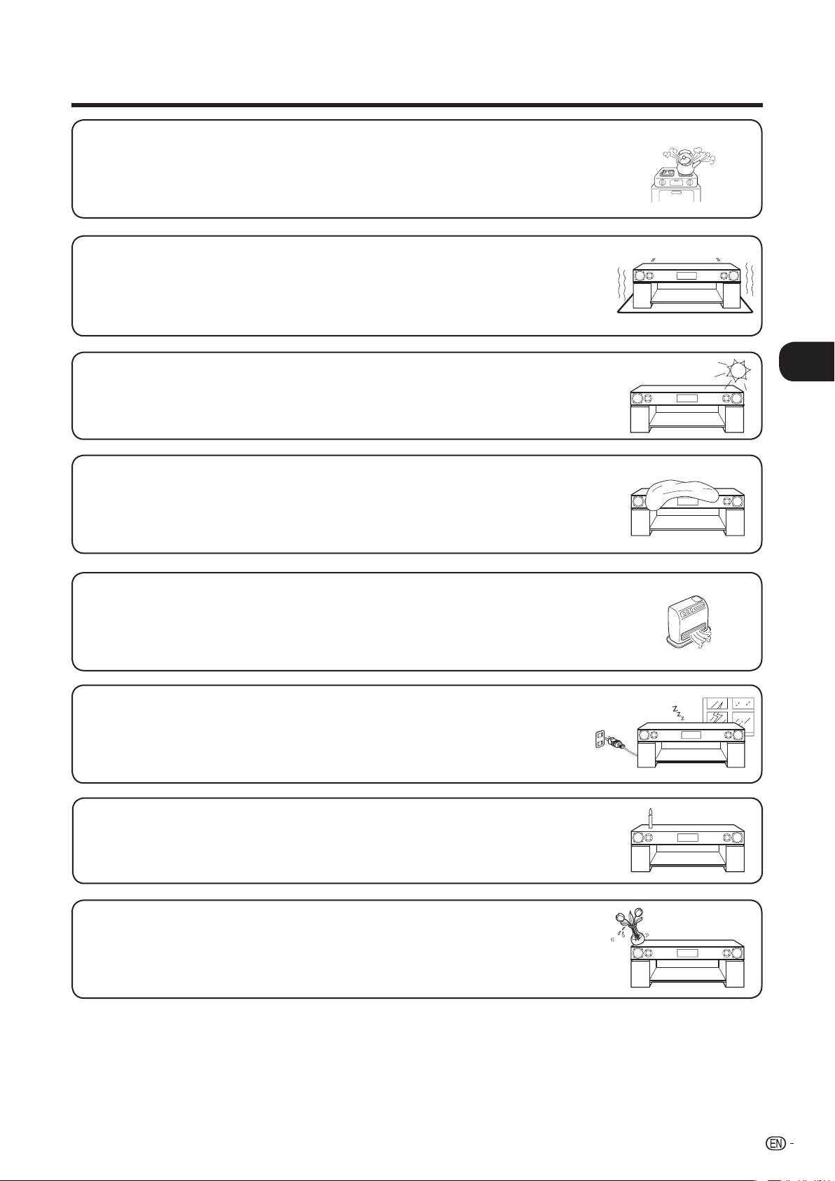
• Do not put the product on an unstable place. If you put the product on an uneven or unstable place, it may
fall down and you may be injured. Put the product on a fl at surface strong enough to take the weight.
n
• Selecting the location — Select a place with no direct sunlight and good ventilation.
General Information
• Ventilation — The vents and other openings in the cabinet are designed for ventilation. Do not cover or
block these vents and openings since insuffi cient ventilation can cause overheating and/or shorten the life of
the product.
• Heat — The product should be situated away from heat sources such as radiators, heat registers, stoves,
or other products that produce heat.
• Lightning — For added protection for this product during a lightning storm, or when it is left unattended
and unused for long periods of time, unplug it from the wall outlet and disconnect the antenna. This will
prevent damage to the equipment due to lightning and power-line surges.
• To prevent fi re, never place any type of candle or fl ames on the top or near the product.
• To prevent fi re or shock hazard, do not expose this product to dripping or splashing.
No objects fi lled with liquids, such as vases, should be placed on the product.
3
Page 6
IMPORTANT SAFETY INSTRUCTIONS
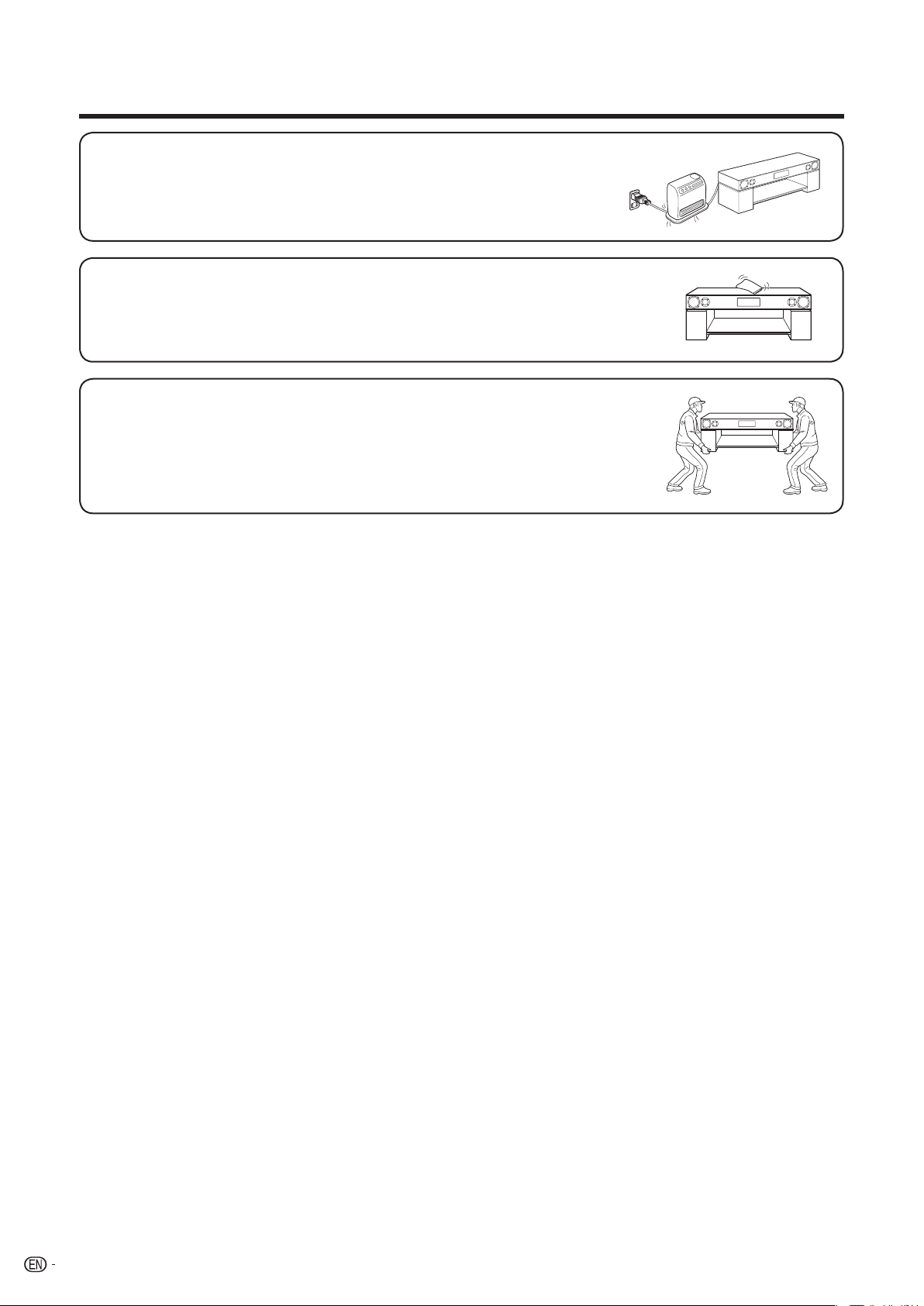
• To prevent fi re or shock hazard, do not place the AC cord under the product or other heavy
items.
• Turn off the main power and unplug the AC cord from the wall outlet before handling.
• To clean the outer cabinet, periodically wipe it with a soft cloth.
• Do not use chemicals for cleaning. It may damage the cabinet fi nish.
• Precautions when transporting this product — Be sure to always carry this product by two people holding
it with two hands — one hand on each side of the this product.
4
Page 7
Precautions
■ General
• Please ensure that the equipment is positioned in a
well-ventilated area and that there is at least 4" (10 cm) of free
space along the sides and back. There must also be a minimum
of 4" (10 cm) of free space on the top of the unit.
• Keep the unit away from direct sunlight, strong magnetic fi elds,
excessive dust, humidity and electronic/ electrical equipment
(home computers, facsimiles, etc.) which generate electrical
noise.
• Do not expose the unit to moisture, to temperatures higher than
140°F (60°C) or to extremely low temperatures.
• If the unit does not work properly, unplug and plug it in again.
Then turn on the unit.
• In case of an electrical storm, unplug the unit for safety.
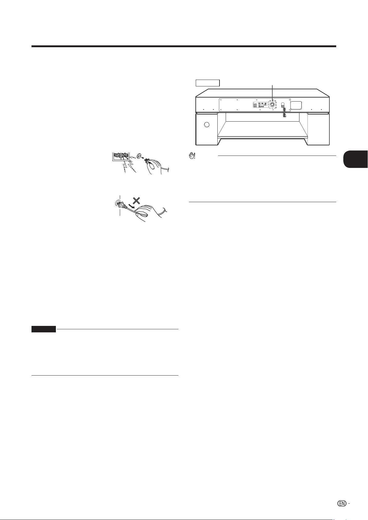
• Hold the AC power plug by the head when removing it from the
AC outlet, as pulling the cord can damage internal wires.
• Do not remove the outer cover, as this may result in electric
shock. Refer internal service to your local SHARP service
facility.
• This unit should only be used within the range of 41°F - 95°F
(5°C - 35°C).
• The ventilation should not be impeded by covering the
ventilation openings with items, such as newspapers,
tablecloths, curtains, etc.
• The apparatus is designed for use in moderate climate.
• Attention should be drawn to the environmental aspects of
battery disposal.
• The glass parts of this product are made of reinforced glass,
but dropping pointed objects on them or strongly hitting a glass
surface may cause it to break. Always take proper precautions.
■ Cooling fan
This unit is fi tted with a cooling fan at the rear for improved cooling.
Do not cover the opening in this section with any obstacles.
Rear view
Caution:
• The unit will get warm while being used. Do not touch the warm
areas of the unit for prolonged periods to avoid damage to you.
• This unit is equipped with a special function which protects the
amplifi er circuit from damages. When it is activated, the sound
switch is turned off. In this case, set the unit to the stand-by mode
and turn on again.
Cooling fan
■ Volume control
The sound level at a given volume setting depends on speaker
effi ciency, location and various other factors. It is advisable to avoid
exposure to high volume levels, which occurs while turning the
unit on with the volume control setting up high, or while continually
listening at high volumes.
n
General Information
Warning:
• The voltage used must be the same as that specifi ed by this unit.
Using this product with a higher voltage other than that specifi ed
is dangerous and may result in a fi re or other types of accident,
causing damage. SHARP will not be held responsible for any
damage resulting from the use of this unit with a voltage other than
that specifi ed.
5
Page 8
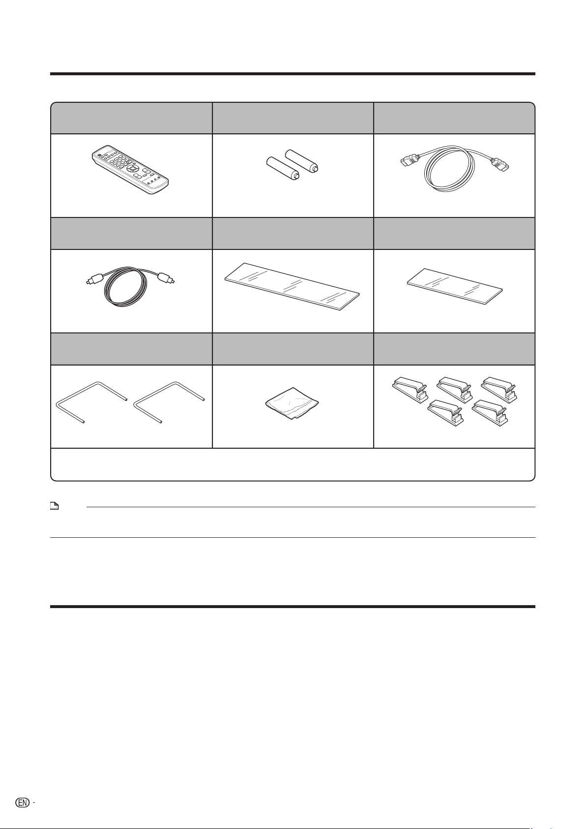
Accessories
Please confi rm that the following accessories are included.
Remote control (x1)
Page 10
Optical digital cable (x1) Top glass cover (x1) Glass shelf (x1)
Pages 14-15 Page 11 Page 11
Wall spacer (x2) Cloth (x1) Cable clamp (x5)
“AA” size battery (x2) HDMI cable (x1)
(UM/SUM-3, R6, HP-7 or similar)
Page 17 Pages 14-15
Page 11 Page 30 Page 12
Operation manual (×1)
NOTE
• Only the above accessories are included.
• The top glass cover, glass shelf, wall spacers and other parts must be installed before use. (Pages 11-12)
Trademarks
• “HDMI”, the HDMI logo and High-Defi nition Multimedia Interface are trademark or registered trademarks of HDMI Licensing
LLC.
• Manufactured under license from Dolby Laboratories. “Dolby”, “Pro Logic”, the double-D symbol, Audistry and the sound
shell logo are trademarks of Dolby Laboratories.
“DTS” and “DTS Digital Surround” are registered trademarks of DTS, Inc.
•
6
Page 9
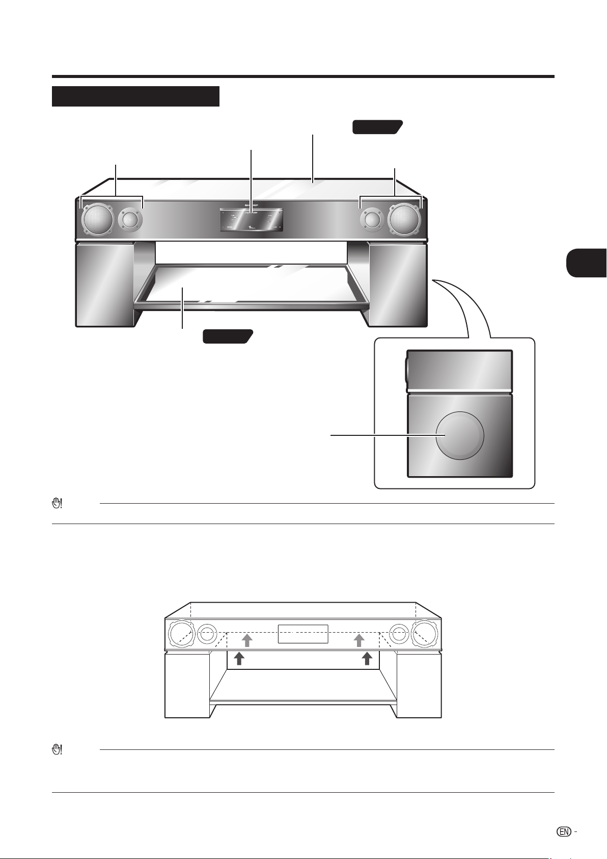
Controls and indicators
Front speaker (L-ch)
• The left-channel sound is
reproduced here.
Front speaker (R-ch)
• The right-channel sound is reproduced here.
Subwoofer
Control/Display part
Top glass cover
Glass shelf
• The low-frequency sound
is reproduced here.
Page 11
Page 11
The top glass cover and glass shelf must be installed before use. (Page 11)
Main unit (front view)
n
General Information
Caution:
• The subwoofer is delicate and should be handled with care.
Handling precautions for the main unit and speakers
Moving or installing the product should be performed by at least two people.
Caution:
• When moving or installing the unit, do not hold it by the speaker mesh. Otherwise the speakers may be damaged.
Grasp the unit at the areas on the underside of the top board, marked by arrows in the illustration shown above.
• Do not carry the unit by holding the metal frame that supports the glass shelf.
7
Page 10
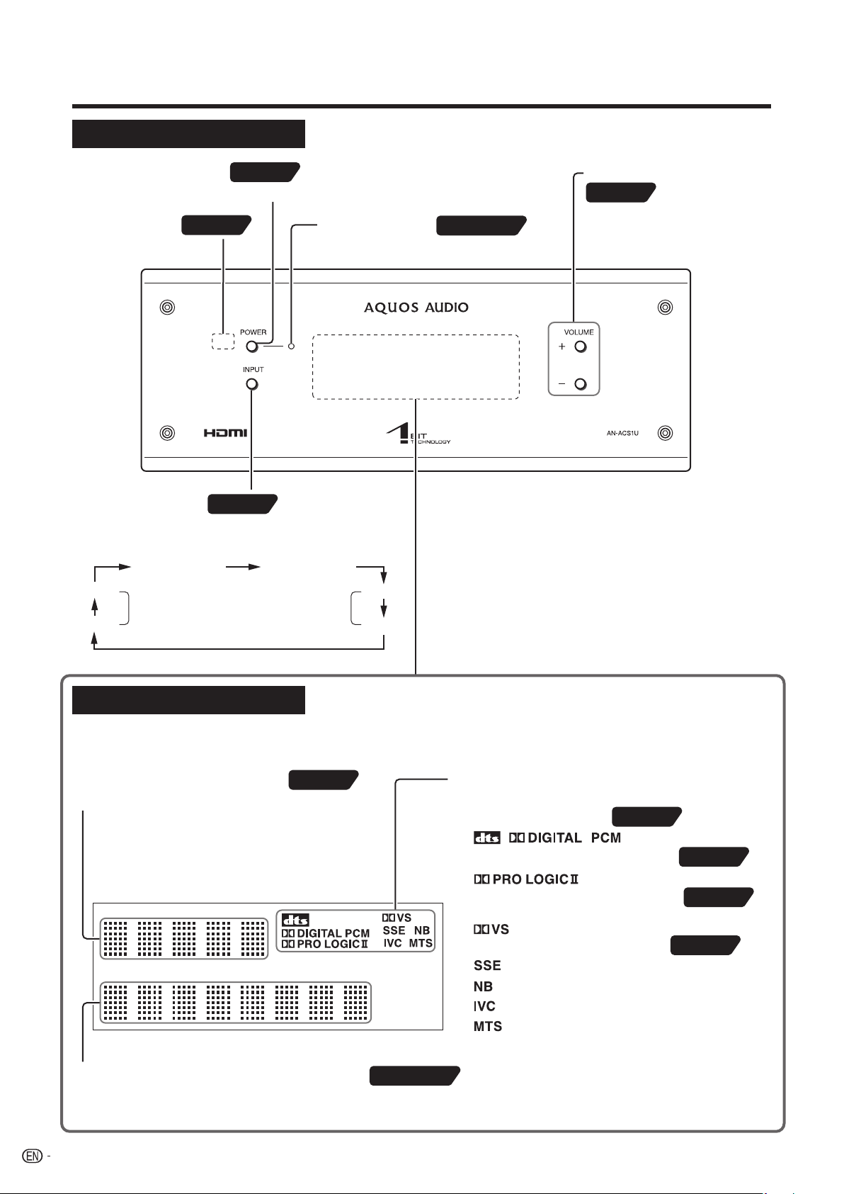
Controls and indicators
Remote sensor
• Point the remote control at
this sensor.
Power indicator
• Lit in green: unit is operating
• Lit in red: unit is in stand-by mode
POWER
• Switches the unit between on and off (stand-by).
INPUT
• Press this button to select the input source. Each
push of the button cycles through the following
settings.
VOLUME +/-
• Turns up/down the volume.
HDMI1 (INPUT) HDMI2 (INPUT)
AUX1
AUX2
AUX4
AUX3
AUDIO INPUT
(ANALOG)
DIGITAL
AUDIO INPUT
(OPTICAL)
Display top row (Input source)
• Shows the currently selected input source.
Display bottom row (Volume/sound mode)
• Shows information about sound mode, volume level, Dolby Virtual
Speaker, Audistry, and other settings.
• Shows the input signal type.
• Lights up when Dolby ProLogic II is active.
• Lights up when Dolby Virtual Speaker mode
is active.
• Lights up when Audistry mode is active.
,,
Page 16
Page 17
Page 19
Page 23
Page 22
Page 20
Page 20
Page 19
Pages 16•19
Pages 18-23
Page 18
Depending on the input signal type and selected settings, one or
more of the following indicators lights up.
……SOUND SPACE
……NATURAL BASS
……INTELLIGENT VOLUME
……MONO TO STEREO
Control part
Display part
Various information about the operating condition of the unit is shown here, including the input source, volume level setting,
sound mode, subwoofer level setting, mute, etc.
8
Page 11
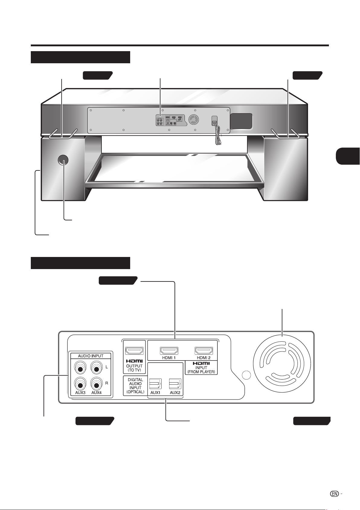
Main unit (rear view)
Wall spacer Amplifier part
Subwoofer
Wall spacer
Page 11Page 11
Bass reflex duct (Do not insert any objects here.)
Cooling fan
• The unit has a built-in fan for improved
cooling. The fan starts up automatically
when power is turned on. Do not block
or cover the fan openings.
AUDIO INPUT
AUX3, AUX4 connectors
• Connect a TV, CD player, cassette deck or other
component with analog audio output (line output)
here.
HDMI INPUT/OUTPUT
HDMI INPUT (FROM PLAYER)
HDMI1, HDMI 2 connectors
• Connect a player or other component with HDMI output
here.
HDMI OUTPUT (TO TV)
• Connect a TV with HDMI input here.
DIGITAL AUDIO INPUT (OPTICAL)
AUX1, AUX2 connectors
• Connect a TV or other component with digital audio output
(optical) here.
Pages 14•15
Pages 14•15 Pages 14•15
Controls and indicators
n
General Information
Amplifi er part
9
Page 12

Controls and indicators
POWER
Remote control transmitter
• Press to turn the power of the unit on
and off (stand-by).
2 5・3 9 ページ
VOLUME +/-
• Press to adjust the volume.
MUTE
• Press to temporarily mute the sound.
SOUND MODE
• Press one of these buttons to select the
sound mode.
TONE
• Press to adjust the tonal quality.
MENU
• Press to display the menu.
DOLBY VIRTUAL
SPEAKER
• Press to turn the Dolby Virtual Speaker
function on and off.
INPUT
• Press one of these buttons to select the
input source.
ENTER
• Press to set a menu or an item.
Audistry sound mode
• Press one of these buttons to select an
Audistry mode.
Cursor
• Press to select menus and items.
SUBWOOFER LEVEL (+/-)
• Press to adjust the Subwoofer level.
Page 16
Page 21
Page 18
Page 18
Page 23
Page 22
Page 18
Page 19
Pages 25-27
Pages 25-27
Pages 18•19
Page 27
Remote control
10
Page 13

Installing the unit
Position the top glass
cover and glass shelf
correctly as shown here.
Glass shelf cushion pads
(already attached to the unit)
Top glass cover
cushion pads
(already attached
to the unit)
Logo sticker
Top glass cover
Glass shelf
Precaution label
Position the top glass
cover and glass shelf
correctly as shown here.
Glass shelf cushion pads
(already attached to the unit)
Top glass cover
cushion pads
(already attached
to the unit)
Logo sticker
Top glass cover
Glass shelf
Precaution label
Before installation
• Because this unit is extremely heavy, it must always be handled by at least
two persons, to prevent the risk of injury and accidents.
• For safety, protective gloves should be worn when handling the unit.
• For information on supplied parts and accessories, please see page 6.
• Take care not to scratch the fl oor etc. when moving the unit.
• Do not touch the speaker mesh on the front side when moving the unit.
Otherwise the mesh or the speakers may be damaged.
• Never place the unit on an unstable surface or any surface unable to sustain
its weight. Otherwise the unit may fall over or drop, and there is a risk of
damage and injury.
• Before moving the unit, be sure to turn power off and disconnect the power
cord from the AC outlet. Also disconnect all cables from other components.
Double-check this before you begin. Otherwise there is a risk of damage and
injury.
• Do not move the unit with a TV or other component on top. Otherwise such a
component may fall over or drop, and there is a risk of damage and injury.
• The glass parts are made of reinforced glass, but dropping pointed objects
on them or strongly hitting a glass surface may cause it to break. Always take
proper precautions.
Speaker mesh sectionsSpeaker mesh sections
o
Placing the top glass cover and glass shelf on the unit
Caution:
•
This procedure should be performed by at least two people.
•
The top glass cover and glass shelf are not fastened to the
unit.
•
After placing the top glass cover and glass shelf on the
unit, take care to keep the unit level when transporting it.
Otherwise these parts may fall off, and there is a risk of
damage and injury.
Attaching the wall spacers
The wall spacers can be attached to the rear side of the top section of the unit (two locations, right and left).
• The wall spacers serve to ensure proper clearance behind the unit and protect the connection cables from damage.
Caution:
•
Do not carry the unit by holding the wall spacers.
•
When moving the unit, grasp it at the areas marked by arrows
on the underside of the top board.
•
Do not carry the unit by holding the metal frame that supports
the glass shelf.
Wall spacer
Wall spacer
(supplied)
(supplied)
Insert wall
Insert wall
spacer here
spacer here
(2 locations)
(2 locations)
Rear view
Rear view
Wall spacer
Wall spacer
(supplied)
(supplied)
Preparation for Use
11
Page 14

Installing the unit
Positioning the unit in the room
Choose the installation location of the unit so that
there is enough room to position the TV, media player,
or other components and to make the necessary
connections.
Caution:
•
Installation should be performed by at least two people.
When moving the unit, take care to keep it level. Otherwise
the top glass cover or glass shelf may fall off, and there is a
risk of damage and injury.
Installing a TV, media player, or similar
Place the TV in the center of the unit.
Top glass cover load carrying capacity : approx. 80 kg (176 lbs.)
Glass shelf load carrying capacity : approx. 25 kg (55 lbs.)
Ensure that there is a
Ensure that there is a
clearance of at least
clearance of at least
10 cm (4 in.) to the
10 cm (4 in.) to the
rear wall.
rear wall.
Cable clamps
Cables connected to the amplifi er section on the rear of the unit can be neatly organized with the supplied cable clamps. Use
these as required.
(1) Attach cable clamp to the unit (2) Fasten cable(s)
Peel off cover
and stick to
the unit
Adhesive
face
Cable(s)
12
Page 15

Connections
• Before making connections, disconnect the power cords from all units.
Refer to the manual of the respective unit for detailed instructions.
• Do not connect HDMI CEC-enabled audio equipment to this unit or to the TV.
Otherwise the AQUOS LINK function will not operate correctly.
■ The audio and video signal fl ow in a system using this unit is shown below.
For details on
connection, please
see pages 14 - 15.
Signal fl ow when using equipment with HDMI connectors AQUOS LINK
Audio signal
Video signal
AQUOS AUDIO system
Optical digital cable
HDMI cable
HDMI cable
Blu-ray Disc player or similar
TV
o
Preparation for Use
NOTE
• We recommend to connect a component with HDMI output to the HDMI input of the AQUOS AUDIO system. If the component is connected
directly to the TV, the sound of the HDMI component sometimes cannot not be reproduced by the AQUOS AUDIO system.
• If the input selector of the AQUOS AUDIO system is not set to HDMI 1 or HDMI 2, the sound from the Blu-ray Disc player or similar
component cannot be reproduced by the TV.
AQUOS LINK function
When connecting an HDMI CEC (Consumer Electronics Control)-enabled AQUOS TV, Blu-ray Disc player, or similar
component, operation of these components in the system can be linked.
(For details on how to use AQUOS LINK function, please see pages 24 - 27.)
Signal fl ow when using equipment without HDMI connectors
TV
Audio signal
Video signal
AQUOS AUDIO system
Optical digital cable
or Audio cable
Optical digital cable
or Audio cable
AV cable
NOTE
• Use only audio cables without integrated resistors. Otherwise the volume level will be reduced.
DVD player/VCR or similar
13
Page 16

Rear panel
(amplifier part)
To HDMI OUTPUT
(TO TV) connector
HDMI cable
To HDMI input connector
To DIGITAL AUDIO
INPUT (OPTICAL)
connector (AUX1)
To DIGITAL AUDIO
output (optical) connector
Optical
digital cable
HDMI
Insert cable until you hear a click.
TV
AUDIO
DIGITAL
Connect both
cables
Connections
Connecting a TV (with HDMI connector) AQUOS LINK
Use both the optical digital cable and HDMI cable for the connection.
To use the AQUOS LINK function (pages 24 - 27), connect the audio signal of the TV to the AUX1 connector. If AUX2 is used,
you must manually select the AUX2 input.
Cables to use
Optical digital cable (supplied)
HDMI cable (supplied)
If the cable is equipped with a protective
cap, remove it before making the
connection.
NOTE
• If only the HDMI cable is used for the
connection, the sound of the TV cannot
be reproduced by the AQUOS AUDIO
system. To reproduce the sound of the
TV with the AQUOS AUDIO system, the
optical digital cable must be connected.
• When connecting an HDMI CEC-enabled
AQUOS TV or similar component, the
AQUOS LINK function can be used.
(Pages 24 - 27)
Connecting a TV (without HDMI connector)
Use the optical digital cable for the connection.
If the TV does not have a digital audio output, use regular audio cable to make an analog connection.
Cables to use
Optical digital cable
(supplied or commercially available)
If the cable is equipped with a protective
cap, remove it before making the
connection.
Audio cable (commercially available)
Left (white)
Right (red)
Left (white)
Right (red)
TV
Audio cable
To AUDIO INPUT
connectors
(AUX3 or AUX4)
Rear panel
(amplifier part)
AUDIO
DIGITAL
or
AUDIO
To AUDIO output jacks
Make one of these
connections (not both)
To DIGITAL AUDIO
output (optical) connector
L
R
Optical
digital cable
To DIGITAL AUDIO INPUT
(OPTICAL) connector
(AUX1 or AUX2)
14
Insert cable until you hear a click.
Page 17

Connections
To HDMI OUTPUT
(TO TV) connector
To HDMI input
connector of TV
To HDMI INPUT
(FROM PLAYER) connector
(HDMI 1 or HDMI 2)
To DIGITAL AUDIO INPUT (OPTICAL)
connector (AUX1)
To DIGITAL AUDIO output
(optical) connector of TV
A single cable carries
both video and audio
information.
Rear panel
(amplifier part)
Blu-ray Disc player
or similar
To HDMI output
connector
To HDMI output
connector
Blu-ray Disc player
or similar
Insert cable until you hear a click.
Connecting a Blu-ray Disc player or similar (with HDMI connector)
AQUOS LINK
Use the HDMI cable for the connection.
Cables to use
HDMI cable
(supplied or commercially available)
If the cable is equipped with a protective
cap, remove it before making the
connection.
NOTE
• When connecting an HDMI CEC-enabled
AQUOS TV, Blu-ray Disc player, or similar
component, the AQUOS LINK function
can be used. (Pages 24 - 27)
• When using a commercially available HDMI
cable, it is recommended to limit cable
length to 3 m (10 ft.), to ensure stable
operation and to prevent image quality
degradation.
o
Preparation for Use
Connecting a DVD player, VCR, or similar (without HDMI connector)
Use optical digital cable or audio cable for the connection.
Optical digital cable
(supplied or commercially available)
If the cable is equipped with a protective
cap, remove it before making the
connection.
Audio cable (commercially available)
Left (white)
Right (red)
NOTE
• Connect the video output of the DVD
player or VCR directly to the TV, using
suitable A/V cable.
Cables to use
DVD player/VCR or similar
To the TV (video)
Left (white)
Right (red)
Audio cable
Rear panel
(amplifier part)
To DIGITAL AUDIO
output (optical) connector
To AUDIO output jacks
AUDIO
Make one of
these connections
(not both)
To AUDIO INPUT
connectors
(AUX3 or AUX4)
Insert cable until you hear a click.
AUDIO
DIGITAL
or
L
R
To DIGITAL AUDIO
INPUT (OPTICAL)
connector (AUX1 or AUX2)
Optical
digital cable
15
Page 18

AC power connection
Connecting the AC power cord
After checking that all the connections have been made correctly, connect the AC power cord to the AC outlet.
Power indicator
lights up in red.
Lit in red
NOTE
Rear panel (amplifier part)
AC120V
60Hz
To AC outlet
• When connecting the power cords of the various components, plug in the
power cord of the TV last.
• If you have connected or disconnected an HDMI cable or have changed
connections, cycle power to the TV (turn it off and then again) while power to all
other components is on.
• Never use a power cord other than the one supplied. Otherwise, a malfunction
or an accident may occur.
• Unplug the AC power cord from the AC outlet if the unit will not be in use for a
prolonged period of time.
• Always turn power off before disconnecting a power cord. Always grasp the
plug and do not pull on the cable, as this can lead to cable break.
To turn the power on
To turn the power on:
Press POWER on the remote control or the main unit.
• The power indicator lights up green.
• If the power does not turn on, check whether the power
cord is plugged in properly.
To set the unit to the stand-by mode:
Press POWER again.
• The power indicator lights up red.
NOTE
• After power-on, there is a mute interval of 8 seconds.
• After the unit enters the stand-by mode, wait a few seconds to turn on again.
Lit in greenLit in green
Lit in redLit in red
16
Page 19

Remote control
Close
Battery installation
1 Open the battery cover.
Open
2 Insert the batteries according to the direction
indicated in the battery compartment.
Insert battery with
side first
3 Close the cover.
Precautions for battery use:
• Replace all old batteries with new ones at the same time.
• Do not mix old and new batteries.
• Remove the batteries if the unit will not be used for long periods of
time. This will prevent potential damage due to battery leakage.
Caution:
•
Do not use rechargeable batteries (nickel-cadmium battery, etc.).
•
Installing the batteries incorrectly may cause the unit to malfunction.
o
Preparation for Use
Test of the remote control
Remote sensor
Approx.
20cm (8 in.)
to 6m (20 ft.)
Approx.
Approx.
15º
15º
Point the remote control directly at the remote sensor on the
main unit.
The remote control can be used within the range shown left.
NOTE
• If the power does not come on, check whether the power cord is
properly plugged in and whether the batteries have been inserted
correctly into the remote control.
• Replace the batteries if the operating distance is reduced or if the
operation becomes erratic.
Purchase 2 “AA” size batteries (UM/SUM-3, R6, HP-7 or similar).
• Periodically clean the transmitter on the remote control and the
sensor on the unit with a soft cloth.
• Exposing the sensor on the unit to strong light may interfere with
operation. Change the lighting or the direction of the unit.
• Keep the remote control away from moisture, heat, shock, and
vibrations.
17
Page 20

General control
Shown for about 3 seconds
NORMAL HEAVY LIGHT
Shown for about 3 seconds
Subwoofer control
The subwoofer level can be adjusted.
Press SUBWOOFER LEVEL.
• The current subwoofer level setting is shown. When you
press the button again while the level is shown (within 3
seconds), you can change the subwoofer level.
To increase the level, press SUBWOOFER LEVEL +.
To decrease the level, press SUBWOOFER LEVEL -.
• If the subwoofer level is too high, resulting in distortion, you
should lower the level.
To change the tonal quality of the sound
You can choose among three sound modes for the tonal
quality.
Volume control
Main unit operation:
Press VOLUME + to increase the volume and VOLUME - for
decreasing.
Remote control operation:
Press VOLUME + to increase the volume and VOLUME - for
decreasing.
Muting
The sound is muted temporarily when pressing MUTE on the
remote control.
Press again to restore the sound.
NOTE
• When you press another button, muting is canceled.
However, it is not canceled if INPUT or MENU is pressed.
• When the unit is tuned off and back on again, muting is canceled.
Press TONE.
• The current sound mode is shown.
When you press the button again while the mode is shown
(within 3 seconds), you can change the sound mode.
• Each push of the button cycles through the following settings.
To dim the display
1 Press MENU.
2 Use c/d to select
“DIM”.
3 Use a to select “ON”
and press ENTER.
• The display will be turned off.
• If DVS or Audistry has been selected, the respective sound
mode icon will be shown also while the display is off.
• If a button is pressed while the display is dimmed, the
current setting will be shown for 3 seconds, and then the
display goes off again.
To cancel the setting
Use b to select “OFF” and then press ENTER.
18
Page 21

Listening to the playback sound
HDMI1
HDMI2
AUX1
AUX2
AUX3
AUX4
Display (top row)
1 Turn on the connected equipment.
2 Press POWER to turn the power on.
The power indicator lights up green.
Lit in green
3 Select the source to be playback.
Main unit operation:
POWER
Power indicator
• Lit in green (unit is operating)
• Lit in red (unit is in stand-by mode)
Press INPUT repeatedly to select a source.
(Before doing this, wait until a source is shown on the
top row of the display.)
• Each push of the button cycles through the following
settings.
(Actual operation will lag slightly behind the display.)
INPUT VOLUME +/
-
p
Basic Operation
Remote control operation:
To select a source, press the corresponding button.
4 Press the play button of the connected
equipment.
5 Adjust the volume level with VOLUME +/-.
6 Enjoy surround sound or various qualities.
7 After use:
Press POWER to enter the stand-by mode.
The power indicator lights up red.
Lit in red
NOTE
• Reduce the volume level with VOLUME +/- before entering the
stand-by mode.
19
Page 22

Enjoying surround sound (sound mode)
This product incorporates decoders supporting the Dolby Digital system and DTS system.
Dolby Digital
One of the digital audio systems for theatrical use.
You can also enjoy the stereophonic effect in the home
theater system.
Lights up when detecting Dolby Digital signal.
DTS (Digital Theater Systems)
One of the digital audio systems for theatrical use.
As the sound quality is emphasized, you can enjoy the
realistic sound effect in the home theater system.
Lights up when detecting DTS signal.
Dolby Pro Logic
System expanding 2ch stereo sound to more spacious sound.
When setting Dolby Virtual Speaker to “ON”, Dolby Pro
Logic is activated to enjoy the stereo sound effect.
Lights up when Dolby Pro Logic
is activated.
PCM (Pulse Code Modulation)
This is a general term for digitally encoded audio signals
on a CD or DVD.
The AQUOS AUDIO system lets you enjoy playback of
digital signals from sources such as CD or DVD.
The indicator lights up when a PCM signal has been detected.
Preset sound modes and sound image
You can enjoy normal stereo sounds.
Creates a strong low end and a dynamic, wide sound stage.
Appropriate for movie soundtracks and similar sources.
Attenuates the bass sound, and enhances the sound clarity
also at lower listening levels.
Appropriate for news programs and similar sources.
Creates a natural, spacious sound.
Appropriate for various kinds of music sources.
Slightly emphasizes both the low frequency and high
frequency range, resulting in transparent sound.
Appropriate for listening to jazz and similar music.
Emphasizes both bass and treble, resulting in brisk and lively
sound.
Appropriate for listening to rock and pop music.
Emphasizes the midrange and creates a spacious impression.
Appropriate for vocal music.
Emphasizes both the low frequency and high frequency
range and creates a spacious impression.
Appropriate for listening to live recordings of concerts and
similar sources.
Voice of narration comes out from the center; you can hear
cheers and feel the atmosphere in the theater with a wide
sound fi eld like 5.1ch.
Appropriate for sports broadcasting such as baseball or
football games.
Slightly emphasizes the low frequency range, and creates an
extended high end.
Appropriate for listening to classical music.
NOTE
• Subwoofer sound levels for preset sound modes are set to the recommended levels.
• You can adjust a subwoofer sound level for each preset sound mode. (Page 18) Return the settings to default by resetting. (Page 29)
20
Words are easy to hear and loud sounds are controlled; even
at low volume, you can enjoy a wide sound fi eld like 5.1ch.
Appropriate for listening to sounds of movies at low volume.
Page 23

Enjoying surround sound (sound mode)
STANDARD
MOVIE
NEWS
MUSIC
JAZZ
CLASSIC
ROCK
POPS
LIVE
SPORTS
NIGHT
: Lights up with multi-channel signal/stereo signal
: Lights up only with multi-channel signal
Preset sound mode
Mode indication on bottom
row of display
Dolby
Virtual
Speaker
Sound
Space
Natural
Bass
Intelligent
Volume
Mono to
Stereo
SSEVS NB IVC MTS
: Lights up only with stereo signal
: Out
The display content differs, depending on the sound mode.
(See table below.)
Preset sound mode
Select any of the 11 preset sound modes already set to the optimal sound quality levels.
Select a desired sound mode by pressing one of the SOUND MODE buttons.
p
Basic Operation
21
Page 24

Enjoying surround sound (sound mode)
Dolby Virtual Speaker (DVS) sound mode
The Dolby Virtual Speaker (DVS) creates virtual surrounds comparable to the 5.1ch sound produced by the 2.1ch speaker.
When DVS is set to “ON” for 2 channel stereo signals, Dolby Pro Logic
converted into 5.1ch. (Page 20)
brings out virtual sound effects through the signals
To set DVS to “ON”, press DOLBY VIRTUAL
SPEAKER.
The Dolby Virtual Speaker indicator lights up.
Press DOLBY VIRTUAL SPEAKER again to return to “OFF”.
ON
The Dolby Virtual Speaker creates multichannel-like sound
effects.
Compared with the MOVIE mode, the bass sound level is
slightly reduced.
The Dolby Pro Logic
signals are detected.
OFF
The Dolby Virtual Speaker is deactivated.
indicator also lights up if 2ch sound
NOTE
• When the DVS mode is set to “ON”, the preset sound mode and Audistry (SOUND SPACE mode, MONO TO STEREO mode) are canceled.
(The NATURAL BASS mode and the INTELLIGENT VOLUME mode are not canceled.)
• Monaural signals do not generate surround effects.
• DVS sound effect may not be obtained depending on signal types (the VS indicator blinks).
In such a case, set the DVS mode to “OFF”.
22
Page 25

Enjoying surround sound (sound mode)
Audistry sound mode
Enjoy a variety of sounds by each or any combination of the 4 modes.
Press the button for your desired mode.
Press it again to cancel.
Display
Symbol for selected
mode lights up.
Display (bottom row)
Sound setting for current mode is shown for 3 seconds.
SOUND SPACE
The 4 speakers create spacious stereo sounds.
(Sound stage expansion)
SSE
indicator lights up
NATURAL BASS
The system’s low-frequency characteristics realize the
optimal bass sounds.
(Bass sound expansion)
NB
indicator lights up
INTELLIGENT VOLUME
Appropriate listener-friendly volumes realized; the volume
is decreased during loud sounds, and increased during
low sounds.
(Peak limiter and expander)
p
IVC
indicator lights up
MONO TO STEREO
You can enjoy monaural sound source with a stereo-like effect.
(Mono stereo conversion)
MTS
indicator lights up
Possible combinations : Enabled : Disabled
SOUND
SPACE
When you select
“SOUND SPACE”
When you select
“NATURAL BASS”
When you select
“INTELLIGENT VOLUME”
When you select
“MONO TO STEREO”
When you select
“DVS”
NOTE
• When setting each mode of Audistry to “ON”, the preset sound mode is canceled.
• When setting the SOUND SPACE or MONO TO STEREO mode to “ON”, the DVS setting is also canceled.
(It is not canceled even if the NATURAL BASS or INTELLIGENT VOLUME mode is set to “ON”.)
• The SOUND SPACE and MONO TO STEREO modes may not be activated depending on the input signal type.
• If the SOUND SPACE or MONO TO STEREO indicator blinks, the effect of these modes cannot be obtained.
NATURAL
BASS
INTELLIGENT
VOLUME
MONO TO
STEREO
Basic Operation
23
Page 26

AQUOS LINK
HDMI cable (supplied)
Optical digital audio cable
(supplied)
Blu-ray Disc player or similar
AQUOS AUDIO system
AQUOS TV
AQUOS TV
remote control
Point towards
AQUOS TV
HDMI cable
(commercially available)
(Use an HDMI certified cable.)
When using a commercially available HDMI cable, it is
recommended to limit cable length to 3 m (10 ft.), to ensure
stable operation and to prevent image quality degradation.
For details on connections, please see pages 14 - 15.
AQUOS LINK function
■ When connecting an HDMI CEC (Consumer Electronics Control)-enabled AQUOS TV, Blu-ray Disc player or other SHARP
product, operation of these components in the system can be linked.
■ Simply by pointing the TV remote control at the AQUOS TV, power on/switching for the AQUOS AUDIO system as well as
volume adjustment, mute, sound mode selection and other functions can be controlled.
The input source setting of the AQUOS AUDIO system is also automatically changed, in conjunction with AQUOS TV or Blu-
ray Disc player operation.
Please note that “By AQUOS AUDIO SP” mode must be selected on the AQUOS LINK MENU of the AQUOS TV for the
above functions to be available. (Only power-off control of the AQUOS AUDIO system is available regardless of this setting.)
Also note that operation and display indication may differ from the contents of this manual if the system includes later
AQUOS LINK products with new functions.
SHARP products supporting AQUOS LINK (as of XX 2007)
AQUOS TV LC-65D64U, LC-65SE94U, LC-52D64U, LC-52SE94U, LC-46D64U,
LC-46SE94U, LC-42D64U, LC-37D64U, LC-32D64U, LC-32GP3U
Blu-ray Disk player BD-HP20
NOTE
• To use the AQUOS LINK functions, the AQUOS AUDIO system and AQUOS TV, Blu-ray Disc player or other components must be connected
with HDMI cable. Connect the AQUOS LINK-enabled SHARP AQUOS TV or Blu-ray Disc player directly to the AQUOS AUDIO system.
• Point the remote control of the AQUOS TV towards the AQUOS TV for operation.
The AQUOS AUDIO system, Blu-ray Disc player, or other components do not receive the remote control signals directly.
• For details, please see the manual of the respective component.
24
Page 27

AQUOS TV remote control (example)
Point towards
AQUOS TV
Open the
flip cover
AQUOS LINK Setup
AQUOS LINK
• Use the remote control of the AQUOS TV and point it
towards the AQUOS TV for operation.
Reproducing the sound of the AQUOS TV
through the AQUOS AUDIO system
You can opt to listen to the TV sound only from the AQUOS
AUDIO system.
1 Press TV POWER.
2 Open the remote control’s fl ip cover.
3 Press OPTION.
• The AQUOS LINK Menu screen appears.
AQUOS LINK
Recorder EPG
Top menu/title list
Media change
By AQUOS AUDIO SP
By AQUOS SP
Sound mode change
Model select
4 Press
a
/b to select “By AQUOS AUDIO SP”,
and then press ENTER.
• The sound from the TV speaker and headphone
terminal is silenced and only the sound from the this
AQUOS AUDIO system is audible.
5 Press OPTION.
• The AQUOS LINK Menu screen disappears.
• If you press the button while the menu screen is off,
the menu screen will appear. In such a case, press the
button once more to turn the menu screen off.
Returning the setting to AQUOS TV sound
reproduction
You can opt to listen to the TV sound only from the AQUOS
TV.
1 Open the remote control’s fl ip cover.
2 Press OPTION.
• The AQUOS LINK Menu displays.
3 Press
NOTE
• The AQUOS TV remote control is not supplied with this product.
• The AQUOS TV remote control may be different depending on the
model.
a
/b to select “By AQUOS SP”, and then
press ENTER.
• The AQUOS AUDIO system goes into mute mode.
p
Basic Operation
25
Page 28

AQUOS LINK
Point towards
AQUOS TV
Open the
flip cover
Reproducing AQUOS TV sound through the AQUOS AUDIO system
• Use the remote control of the AQUOS TV and point it
towards the AQUOS TV for operation.
1 Press POWER.
• Along with the AQUOS TV, power to the AQUOS
AUDIO system is turned on automatically.
• The input source of the AQUOS AUDIO system is
automatically set to “AUX1”.
2 Use VOLUME +/- to adjust the volume.
• The volume level is displayed on the AQUOS TV and
on the AQUOS AUDIO system.
3 Try out various preset sound modes.
1. Press OPTION.
• The AQUOS LINK Menu screen appears.
2. Use a/b to select “Sound mode change” and press
ENTER.
• Each push of ENTER cycles through the following
settings.
STANDARD
NIGHT SPORTS LIVE POPS ROCK CLASSIC
3. Press OPTION.
• The AQUOS LINK Menu screen disappears.
MOVIE NEWS MUSIC JAZZ
4 After use:
Press POWER to enter the stand-by mode.
• Along with the AQUOS TV, power to the AQUOS
AUDIO system is turned off automatically.
To switch the sound of SAP broadcasts
Press AUDIO repeatedly to select the desired audio mode.
• For details, please see the manual of the TV.
Muting:
The sound is muted temporarily when pressing MUTE on the
remote control.
To restore the sound, press the button again or press
VOLUME +/-.
NOTE
• To reproduce the sound of another component connected to
AUX2 - AUX4, press INPUT on the AQUOS AUDIO system to
change the setting. (Page 19)
Power on/off, volume adjustment, mute, and other functions can
be linked to the AQUOS TV.
• When an AQUOS LINK-enabled Blu-ray Disc player connected to
HDMI 1 or HDMI 2 is used, the input setting of the AQUOS AUDIO
system and the AQUOS TV is automatically selected as required.
(Operating a menu or similar will also have the same effect.)
• When two AQUOS LINK-enabled players are connected to the
AQUOS AUDIO system, the most recently operated component
will be automatically selected.
• To use the AQUOS TV remote control for selecting one of two AQUOS
LINK-enabled players connected to HDMI 1 and HDMI 2, bring up the
AQUOS LINK MENU screen and use the "Model select" option. Each
push of ENTER cycles through the connected components.
• The AQUOS TV remote control is not supplied with this product.
The AQUOS TV remote control may be different depending on the model.
•
26
Page 29

AQUOS LINK
3 Use a to select
“ON” and press
ENTER.
To cancel the setting
Use b to select "OFF" and then press ENTER.
Enabling the low power stand-by mode
In the factory default condition, the unit is set up so that also
while power of the AQUOS AUDIO system is off, it is possible
to play back video and audio from a non-HDMI CEC-enabled
component (such as a media player) on the AQUOS TV. This
is called the "HDMI ON" mode.
If you change the setting to "HDMI AUTO", the above
function will no longer be available, but the low power
stand-by mode enables the unit to operate effi ciently and
conserve electrical power. (page 30)
When an HDMI CEC-enabled component (such as a media
player) is used, the video and audio can be played back and
controlled with the AQUOS TV at any time, regardless of the
HDMI ON or HDMI AUTO setting.
• Use the remote control of the AQUOS AUDIO system and
point it towards this unit.
Correcting a time lag during Blu-ray
Disc playback between image as
seen on AQUOS TV and sound as
reproduced by AQUOS AUDIO system
If you feel that there is a slight mismatch (lip sync error)
between the image as seen on the AQUOS TV and the sound
as reproduced by the AQUOS AUDIO system, you can set
the audio delay (DLY) function to ON.
This will delay the sound reproduced by the AQUOS AUDIO
system, which serves to reduce the discrepancy between
audio and video.
1 Press MENU.
1 Press MENU.
2 Use c/d to
select “HDMI”.
3 Use b to select
“AUTO” and
press ENTER.
To cancel the setting
Use the a button to select "ON" and then press ENTER.
NOTE
• When using a non-HDMI CEC-enabled component, the "HDMI
ON" mode is recommended. In the "HDMI AUTO" mode, video
and audio from the component cannot be played on the AQUOS
TV while the AQUOS AUDIO system is turned off.
p
Basic Operation
2 Use c/d to
select “DLY”.
27
Page 30

Troubleshooting chart
Many potential problems can be resolved by the owner without calling a service technician.
If something is wrong with this product, check the following before calling your authorized SHARP dealer or service center.
General
Symptom Possible cause
No sound is heard. • Is input switching (selection) proper?
The sound from subwoofer is not
well balanced.
Left and right channels are
reversed.
Noise is heard during playback. • Move the unit away from any computers or mobile phones. –
When a button is pressed, the
unit does not respond.
The power is not turned on. • Is the unit unplugged?
The information is not displayed
even if the unit is turned on.
• Is muting activated?
• Is the volume level set to “0”?
• Is power to the connected source component turned on?
• Is the source component connected to the correct input?
• Is the subwoofer sound level set to the minimum or maximum level? P. 18
• Are the analog audio cables for left channel and right channel connected to the correct
input?
• Set this unit to the stand-by mode and then turn it back on.
If the unit is still malfunctions, reset it.
•The protection circuit may be activated.
Unplug and plug in the power cord again after 5 minutes or more.
• Is the display set to the DIM mode?
Set the DIM mode to OFF.
Reference
page
P. 19, 26
P. 18
P. 18
P. 14, 15
P. 14, 15
P. 16, 29
P. 16
P. 29
P. 18
–
AQUOS LINK
Symptom Possible cause
AQUOS LINK function does not
work properly.
AQUOS TV remote control does
not operate the AQUOS AUDIO
system.
Cannot reproduce sound from
AQUOS TV with the AQUOS
AUDIO system.
No sound or picture. • Is HDMI compliant equipment being used?
Power goes off suddenly. • Is the HDMI cable connected correctly?
Switching on the player does
not turn on the AQUOS AUDIO
system or AQUOS TV.
During playback of video media
from the player, there is a time shift
(lip sync error) between the image
on the AQUOS TV and the sound
from the AQUOS AUDIO system.
• Is the HDMI cable properly connected?
Connect the HDMI cable correctly and then perform the reset procedure.
• Try switching the input manually to check whether video from the player is reproduced.
• Is the AQUOS TV remote control being pointed at the AQUOS TV?
• Is the AQUOS TV set to “By AQUOS AUDIO SP” mode?
• Is an HDMI CEC-enabled component being used?
• Check whether the batteries of the AQUOS TV remote control are still good.
• Are the AQUOS TV audio output and the AUX1 connector on the AQUOS AUDIO
system connected correctly via optical fi ber audio cable?
• Is the AQUOS TV set to “By AQUOS AUDIO SP” mode?
• Is the HDMI cable connected correctly?
Connect the HDMI cable correctly and then perform the reset procedure.
• Do not connect or disconnect an HDMI cable while power is on. This may lead to
operation problems and can cause the picture to disappear.
Connect the HDMI cable correctly and then perform the reset procedure.
• Try setting the player to the playback condition.
When playback is activated, power to the AQUOS AUDIO system and AQUOS TV
should come on.
• Try setting the audio delay function (DLY) to ON. This will delay the sound reproduced by
the AQUOS AUDIO system, which serves to reduce the lip sync error.
Reference
page
P. 14, 15
P. 19
P. 24
P. 25
–
–
P. 14
P. 25
–
P. 14, 15
P. 29
–
P. 14, 15
P. 29
–
P. 27
Remote control
Symptom Possible cause
The remote control does not
operate properly.
The unit cannot be turned on with
the remote control.
28
• Is the battery polarity respected?
• Are the batteries dead?
• Is the distance or angle incorrect?
• Are there any obstructions in front of the unit?
• Is the remote control sensor exposed to strong light (inverter fl uorescent light, direct
sunlight, etc.)?
• Is the remote control for another equipment used simultaneously?
• Is the AC power cord of the unit plugged in?
• Are the batteries inserted?
Reference
page
P. 17
–
P. 17
–
P. 17
–
P. 16
P. 17
Page 31

Error indications and warnings
When you fail to perform operations properly, the following messages are displayed on the unit.
Error message Possible Error
• The cooling fan at the rear of the unit does not run.
Æ Unplug the AC power cord and check if foreign objects get caught around the cooling fan. (*)
(Shown for 3 seconds)
• Malfunction of the surround circuit.
Æ If there are possible noise sources in the vicinity (such as a computer or mobile phone), move
these further away, or try plugging their power cords into a different AC outlet from the AQUOS
AUDIO system. (*)
• Malfunction of circuits other than the surround circuit.
Æ If there are possible noise sources in the vicinity (such as a computer or mobile phone), move
these further away, or try plugging their power cords into a different AC outlet from the AQUOS
AUDIO system. (*)
When HDMI, AUX1 or AUX2 is
selected, all audio input indicators
(PCM, DOLBY DIGITAL, DTS) are
out.
* *
(Shown for 3 seconds)
: Number
* *
Power indicator
(blinks red)
(*) Should the same message appear even if the unit is unplugged and plugged in or is set to the stand-by mode and on again,
contact your local dealer where you purchased the unit.
• When there is no input signal.
Æ Play back the connected equipment.
• Nonstandard signal. Cannot be recognized.
Æ Signals other than DOLBY DIGITAL, DTS, Linear PCM cannot be recognized.
• Poor connection of the digital audio input terminal.
Æ Turn off the unit and check if the cable is connected properly.
• Diagnostic self-check has returned an error.
Æ If there are possible noise sources in the vicinity (such as a computer or mobile phone), move
these further away, or try plugging their power cords into a different AC outlet from the AQUOS
AUDIO system. (*)
• Is volume setting very high?
• Is unit placed in a very hot location?
Æ If the system is operated at very high volume levels or in a hot location for an extended period, the
protection circuitry may be triggered.
Unplug the AC power cord and plug it in again after 5 minutes or more.
Then check the operation. (*)
Reset procedure
■ If trouble occurs
When this product is subjected to strong external interference (mechanical shock, excessive static electricity, abnormal
supply voltage due to lightning, etc.) or if it is operated incorrectly, it may malfunction.
Power indicator
Reset procedure
Hold down POWER (for about 8 seconds).
• Keep the button depressed until the power indicator goes out.
• When the power indicator has gone out, the reset procedure is
completed.
Returning the system to the factory default condition (initialization)
1 Hold down POWER and INPUT together (for about 8
seconds).
2 When the power indicator goes out, release POWER.
The power indicator lights up in green and the indication “INIT”
is shown for about one second on the display. The power then
goes out and the power indicator color changes to red. The
procedure is now completed.
When the indication “INIT” is shown, you can release INPUT.
Power indicator
POWER button
POWER button
INPUT buttonPOWER button
INPUT buttonPOWER button
q
References
DisplayPower indicator
DisplayPower indicator
29
Page 32

Specifi cations
As part of our policy of continuous improvement, SHARP reserves the right to make design and specifi cation changes for product
improvement without prior notice. The performance specifi cation fi gures indicated are nominal values of production units. There may be
some deviations from these values in individual units.
● Main unit
Amplifi er section
Power source AC 120V, 60 Hz
Power consumption Power on : 75W
Stand-by mode : 4.35W
Low power stand-by mode : 0.76W
Amplifi cation system
1-bit switching frequency 11.2MHz
Power output (FTC) Front : 25W watts minimum RMS per channel into 4 ohms from 100 Hz to 20 kHz, 10 % total
Input terminals HDMI input : 19-pin standard connector type g 2
Output terminal HDMI output : 19-pin standard connector type g 1
Speaker section
Front Speaker 2-way speaker system (Magnetic shield)
Subwoofer Bass refl ex system
General
Dimensions Overall : 51-3/4 (W) g 18-3/4 (H) g 17-3/16 (D)"
Weight
Weight Capacity Top glass cover : 176 lbs. (80 kg)
Front speaker : 1-bit
Subwoofer : Pulse width modulation
harmonic distortion
Subwoofer :100W watts minimum RMS into 3 ohms from 70 Hz to 130 Hz,10 % total harmonic distortion
Optical digital Input : Square type g 2
Audio input : RCA-pin type g 2
Woofer : 4" (10 cm) g 2 (4q)
Soft domed tweeter : 1" (2.5 cm) g 2 (6q)
Woofer : 6-5/16" (16 cm) g 1 (3q)
1,315 (W) g 476 (H) g 436 (D)mm
Top glass cover : 51-3/16 (W) g 14-7/8 (D)"
1,300 (W) g 377 (D)mm
Glass shelf : 34-9/16 (W) g 8-3/4 (H) g 14-3/4 (D)"
878 (W) g 224 (H) g 377 (D)mm
●●● lbs. (●● kg)
Glass shelf : 55 lbs. (25 kg)
(delta-sigma) modulation
● Remote control
Remote control
Power source DC 3V [“AA” size (UM-3, R02, HP-15 or similar) battery g 2]
Maintenance
■ Cleaning the cabinet
Periodically wipe the cabinet with a soft cloth and a diluted soap solution,
then with a dry cloth.
• Do not use chemicals for cleaning (gasoline, paint thinner, etc.). It may
damage the cabinet fi nish.
• Do not apply oil to the inside of the each component. It may cause
malfunctions.
30
Page 33

CONSUMER LIMITED WARRANTY
SHARP ELECTRONICS CORPORATION warrants to the first consumer purchaser that this Sharp brand product (the
“Product”), when shipped in its original container, will be free from defective workmanship and materials, and agrees that
it will, at its option, either repair the defect or replace the defective Product or part thereof with a new or remanufactured
equivalent at no charge to the purchaser for parts or labor for the period(s) set forth below.
This warranty does not apply to any appearance items of the Product or if the serial number or model number affixed to
the Product has been removed, defaced, changed, altered or tampered with. This warranty does not cover installation
or signal reception problems. This limited warranty will not apply if the Product has been or is being used in a commercial setting or application; this warranty is meant solely for the non-commercial, household use of the Product by
consumers in their home or residence.
In order to enforce the rights under this limited warranty, the purchaser should follow the steps set forth below and
provide proof of purchase to the servicer.
To the extent permitted by applicable state law, the warranties set forth are in lieu of, and exclusive of, all other warranties, express or implied. Specifically ALL OTHER WARRANTIES OTHER THAN THOSE SET FORTH ABOVE ARE
EXCLUDED, ALL EXPRESS AND IMPLIED WARRANTIES INCLUDING THE WARRANTIES OF MERCHANTABILITY,
FITNESS FOR USE, AND FITNESS FOR A PARTICULAR PURPOSE ARE SPECIFICALLY EXCLUDED. IF, UNDER APPLICABLE STATE LAW, IMPLIED WARRANTIES MAY NOT VALIDLY BE DISCLAIMED OR EXCLUDED, THE DURATION OF
SUCH IMPLIED WARRANTIES IS LIMITED TO THE PERIOD(S) FROM THE DATE OF PURCHASE SET FORTH BELOW.
THIS WARRANTY GIVES YOU SPECIFIC LEGAL RIGHTS. YOU MAY ALSO HAVE OTHER RIGHTS WHICH VARY
FROM STATE TO STATE.
The warranties given herein shall be the sole and exclusive warranties granted by Sharp and shall be the sole and exclusive remedy available to the purchaser and only for the time periods set forth herein. No other representations or promises made by anyone are permitted. Correction of defects, in the manner and for the period of time described herein,
shall constitute complete fulfillment of all liabilities and responsibilities of Sharp to the purchaser with respect to the
Product, and shall constitute full satisfaction of all claims, whether based on contract, negligence, strict liability or otherwise. Sharp does not warrant nor shall Sharp be liable, or in any way responsible, for Products which have been subject
to abuse (including, but not limited to, improper voltage), accident, misuse, negligence, lack of reasonable care, alteration, modification, tampering, improper operation or maintenance or any damages or defects in the Product which were
caused by repairs or attempted repairs performed by anyone other than a Sharp authorized servicer. Nor shall Sharp be
liable or in any way responsible for any incidental or consequential economic or property damage. Some states do not
allow limits on warranties or on remedies for breach in certain transactions; in such states, the limits herein may not
apply.
THIS LIMITED WARRANTY IS VALID ONLY IN THE FIFTY (50) UNITED STATES, THE DISTRICT OF COLUMBIA. AND
PUERTO RICO
Model Specific Section
Where to Obtain Service:
From a Sharp Authorized Servicer located in the United
States. To find the location of the nearest Sharp Authorized
Servicer, call Sharp toll free at 1-800-BE-SHARP.
What to do to Obtain Service:
Please transport the Product in its original packaging and
ensure that the Product is covered to avoid scratches and
damage. Sharp shall not be responsible for lost, stolen or
misdirected mail or for damage to the product incurred
during shipping.
Additional Item(s) Excluded from
Warranty Coverage (if any): Non-rechargeable batteries.
Warranty Period for this Product: One (1) year parts and labor from the date of purchase.
TO OBTAIN PRODUCT INFORMATION, CALL 1-800-BE-SHARP OR VISIT www.sharpusa.com
Your Product Model Number & Description:
(Be sure to have this information available when you need
service for your Product.)
CONSUMER LIMITED WARRANTY
(Valid for warranty service in the U.S. and PUERTO RICO only)
AN-ACS1U 1-BIT THEATER RACK SYSTEM
31
Page 34

Memo
32
Page 35

Page 36

SHARP ELECTRONICS CORPORATION
Sharp Plaza, Mahwah, New Jersey 07430-2135
SHARP CORPORATION
Printed in Malaysia
Impreso en Malasia
TINSEA141WJQZ
08P02-MA-NM
 Loading...