

Page 1
SERVICE MANUAL
CODE: 00ZAL800L/F1E
DIGITAL COPIER
AL-800L/800
MODEL
CONTENTS
[1] SYSTEM CONFIGURATION . . . . . . . . . . . . . . . . . . . . . . . . . . . . . 1-1
[2] SPECIFICATIONS . . . . . . . . . . . . . . . . . . . . . . . . . . . . . . . . . . . . . 2-1
[3] CONSUMABLE PARTS . . . . . . . . . . . . . . . . . . . . . . . . . . . . . . . . . 3-1
[4] SET UP. . . . . . . . . . . . . . . . . . . . . . . . . . . . . . . . . . . . . . . . . . . . . . 4-1
[5] EXTERNAL VIEW AND INTERNAL STRUCTURE . . . . . . . . . . . . 5-1
[6] MACHINE OPERATION. . . . . . . . . . . . . . . . . . . . . . . . . . . . . . . . . 6-1
[7] ADJUSTMENTS, SETTING . . . . . . . . . . . . . . . . . . . . . . . . . . . . . . 7-1
AL-840
[8] SIMULATION (Test Command)/USER PROGRAM . . . . . . . . . . . . 8-1
[9] DISASSEMBLY, ASSEMBLY, MAINTENANCE. . . . . . . . . . . . . . . 9-1
[10] TROUBLESHOOTING . . . . . . . . . . . . . . . . . . . . . . . . . . . . . . . . . 10-1
[11] ACTUAL WIRING CHART . . . . . . . . . . . . . . . . . . . . . . . . . . . . . . 11-1
Parts marked with “ ” are important for maintaining the safety of the set. Be sure to replace these parts with
specified ones for maintaining the safety and performance of the set.
This document has been published to be used
SHARP CORPORATION
for after sales service only.
The contents are subject to change without notice.
Page 2
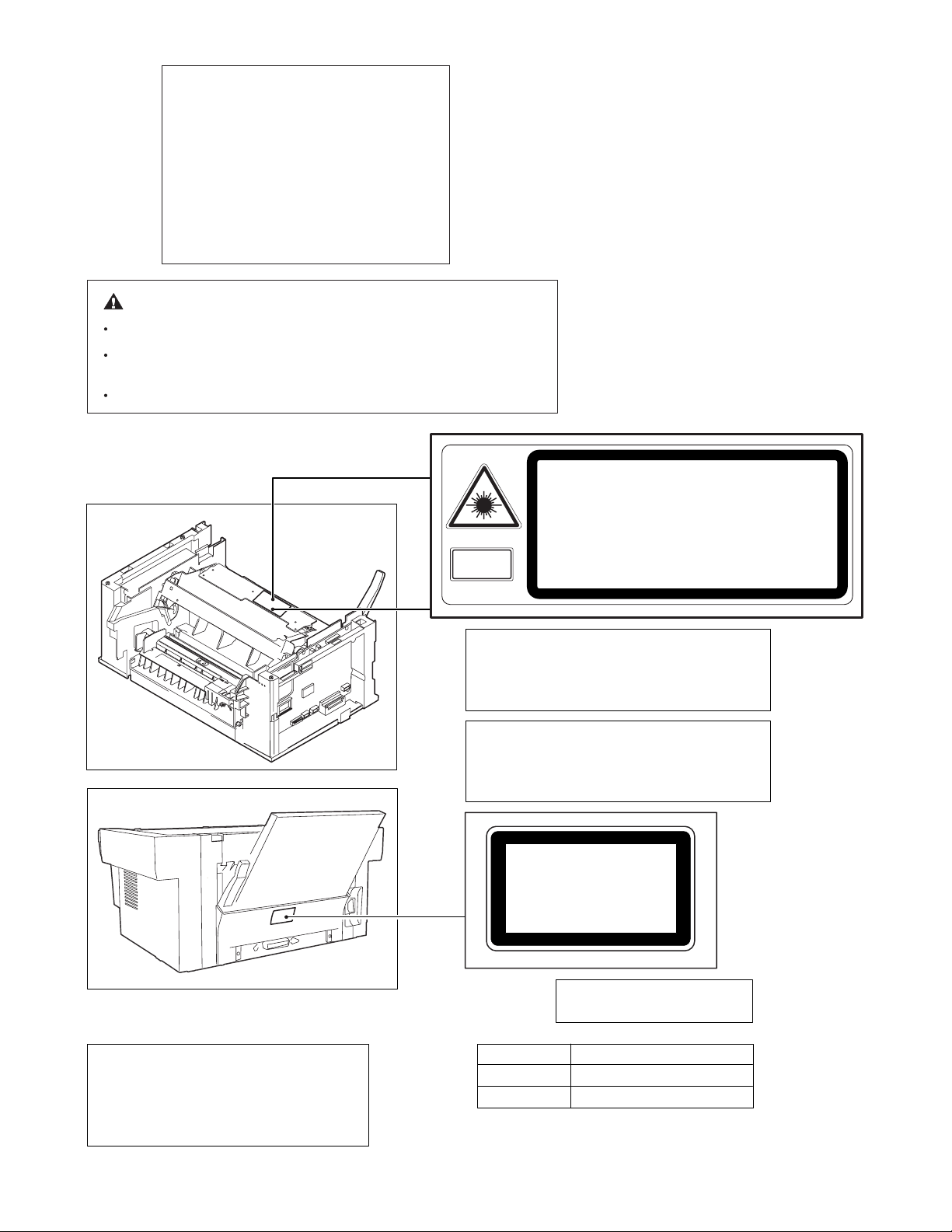
At the production line, the output power of
the scanner unit is adjusted to 0.33
MILLI-WATT PLUS 20 PCTS and is
maintained constant by the operation of the
Automatic Power Control (APC).
Even if the APC circuit fails in operation for
some reason, the maximum output power
will only be 15 MILLI-WATT 0.1 MICROSEC. giving an acceptable emission level of
42 MICRO-WATT which is still-less than the
limit of CLASS-1 laser product.
Caution
The fusing unit is hot. Exercise care when inspecting it.
Do not switch the printer rapidly on and off. After turning the printer off,
wait 10 to 15 seconds before turning it back on.
Printer power must be turned off before installing any supplies.
CAUTION
VORSICHT
ADVARSEL
ADVERSEL
Laserstrahl
VAROITUS! LAITTEEN KÄYTTÄMINEN MUULLA
KUIN TÄSSÄ KÄYTTÖOHJEESSA MAINITULLA
TAVALLA SAATTAA ALTISTAA KÄYTTÄJÄN
TURVALLISUUSLUOKAN 1 YLITTÄVÄLLE
NÄKYMÄTTÖMÄLLE LASERSÄTEILYLLE.
VARNING - OM APPARATEN ANVÄNDS PÅ ANNAT
SÄTT ÄN I DENNA BRUKSANVISNING
SPECIFICERATS, KAN ANVÄNDAREN UTSÄTTAS
FÖR OSYNLIG LASERSTRÅLNING, SOM
ÖVERSKRIDER GRÄNSEN FÖR LASERKLASS 1.
VARNING
VARO!
INVISIBLE LASER RADIATION WHEN OPEN AND INTERLOCKS
DEFEATED AVOID EXPOSURE TO BEAM.
UNSICHTBARE LASERSTRAHLUNG WENN ABDECKUNG GEÖFFNET UND SICHERHEITSVERRIEGELUNG ÜBERBRÜCKT. NICHT DEM STRAHL AUSSETZEN.
USYNLIG LASERSTRÅLNING VED ÅBNING. NÅR SIKKERHEDSBRYDERE ER UDE AF FUNKTION. UNDGÅ UDSAETTELSE FOR STRÅLNING.
USYNLIG LASERSTRÅLING NÅR DEKSEL ÅPNES OG SIKKERHEDSLÅS BR YTES.
UNNGÅ EKSPONERING FOR STRÅLEN.
OSYNLIG LASERSTRÅLNING NÄR DENNA DEL ÄR ÖPPNAD OCH SPÄRRAR ÄR
URKOPPLADE. STRÅLEN ÄR FARLIG. BETRAKTA EJ STRÅLEN
AVATTAESSA JA SUOJALUKITUS OHITETTAESSA OLET ALTTIINA
NÄKYMÄTÖNTÄ LASERSÄTEILYLLE. ÄLÄ KATSO SÄTEESEEN
CLASS 1
LASER PRODUCT
LASER KLASSE 1
.
.
The foregoing is applicable only to the 220V
model, 230V model and 240V model.
Caution
This product contains a low power laser
device. To ensure continued safety do not
remove any cover or attempt to gain access
to the inside of the product. Refer all
servicing to qualified personnel.
Wave length
Pulse times
Output Power
LUOKAN 1 LASERLAITE
KLASS 1 LASER APPARAT
780 ± 15nm
(9.3 ± 2µs)/7mm
0.4mW ± 0.05mW
Page 3

CONTENTS
[1] SYSTEM CONFIGURATION . . . . . . . . . . . . . . . . . . . . . . . . . .1-1
1. Lineup . . . . . . . . . . . . . . . . . . . . . . . . . . . . . . . . . . . . . . . . . 1-1
2. Structure . . . . . . . . . . . . . . . . . . . . . . . . . . . . . . . . . . . . . . .1-3
3. Software (AL-840 only) . . . . . . . . . . . . . . . . . . . . . . . . . . . .1-4
4. Operating environment (AL-840 only). . . . . . . . . . . . . . . . . 1-4
[2] SPECIFICATIONS . . . . . . . . . . . . . . . . . . . . . . . . . . . . . . . . . . 2-1
1. Basic specifications . . . . . . . . . . . . . . . . . . . . . . . . . . . . . .2-1
2. Operation (Performance) . . . . . . . . . . . . . . . . . . . . . . . . . .2-1
3. Engine specification . . . . . . . . . . . . . . . . . . . . . . . . . . . . . .2-5
[3] CONSUMABLE PARTS . . . . . . . . . . . . . . . . . . . . . . . . . . . . . .3-1
1. Configuration . . . . . . . . . . . . . . . . . . . . . . . . . . . . . . . . . . .3-1
2. List . . . . . . . . . . . . . . . . . . . . . . . . . . . . . . . . . . . . . . . . . . .3-1
3. Details. . . . . . . . . . . . . . . . . . . . . . . . . . . . . . . . . . . . . . . . . 3-1
4. Paper specifications . . . . . . . . . . . . . . . . . . . . . . . . . . . . . .3-3
5. Standard density sample . . . . . . . . . . . . . . . . . . . . . . . . . .3-4
6. Environmental conditions . . . . . . . . . . . . . . . . . . . . . . . . . .3-5
[4] SET UP . . . . . . . . . . . . . . . . . . . . . . . . . . . . . . . . . . . . . . . . . . .4-1
1. Installing conditions . . . . . . . . . . . . . . . . . . . . . . . . . . . . . .4-1
2. Unpacking. . . . . . . . . . . . . . . . . . . . . . . . . . . . . . . . . . . . . . 4-1
3. Parts and consumable parts setup . . . . . . . . . . . . . . . . . . . 4-2
4. Cable connection (AL-840 only) . . . . . . . . . . . . . . . . . . . . .4-4
5. Installing the printer driver software (AL-840 only) . . . . . . .4-4
[5] EXTERNAL VIEW AND INTERNAL STRUCTURE . . . . . . . . .5-1
1. List . . . . . . . . . . . . . . . . . . . . . . . . . . . . . . . . . . . . . . . . . . .5-1
2. Contents . . . . . . . . . . . . . . . . . . . . . . . . . . . . . . . . . . . . . . .5-1
[6] MACHINE OPERATION. . . . . . . . . . . . . . . . . . . . . . . . . . . . . .6-1
(1) Operation mode . . . . . . . . . . . . . . . . . . . . . . . . . . . . . . . .6-1
(2) Machine status and display . . . . . . . . . . . . . . . . . . . . . . .6-1
(3) Relationship between the power save mode and
the display and machine operations. . . . . . . . . . . . . . . . . 6-2
(4) Consumable parts life and operation . . . . . . . . . . . . . . . . 6-2
(5) Selection between the ON LINE mode and
the OFF LINE mode (AL-840 only) . . . . . . . . . . . . . . . . . 6-2
(6) Paper width detection and machine operation
(AL-800/840) . . . . . . . . . . . . . . . . . . . . . . . . . . . . . . . . . . 6-2
(7) Auto copy function . . . . . . . . . . . . . . . . . . . . . . . . . . . . . . 6-2
(8) AE level adjustment procedure . . . . . . . . . . . . . . . . . . . . 6-2
(9) Toner save mode setup and cancel . . . . . . . . . . . . . . . . . 6-3
(10) Smart sharing (Auto interface selection) (AL-840 only) . . 6-3
(11) Others . . . . . . . . . . . . . . . . . . . . . . . . . . . . . . . . . . . . . . .6-3
[7] ADJUSTMENTS, SETTING. . . . . . . . . . . . . . . . . . . . . . . . . . . 7-1
1. List . . . . . . . . . . . . . . . . . . . . . . . . . . . . . . . . . . . . . . . . . . . 7-1
2. Details . . . . . . . . . . . . . . . . . . . . . . . . . . . . . . . . . . . . . . . . 7-1
[SET M1] Specifications setting . . . . . . . . . . . . . . . . . . . . 7-1
[SET M2] Counter setting . . . . . . . . . . . . . . . . . . . . . . . . . 7-2
[ADJ M1] Copy density adjustment . . . . . . . . . . . . . . . . . 7-2
[ADJ M2] Copy image distortion adjustment
(AL-800/840). . . . . . . . . . . . . . . . . . . . . . . . . . . 7-4
[ADJ M3] Copy magnification ratio adjustment
(AL-800/840). . . . . . . . . . . . . . . . . . . . . . . . . . . 7-8
[ADJ M3] Copy magnification ratio adjustment
(AL-800/840). . . . . . . . . . . . . . . . . . . . . . . . . . 7-11
[ADJ M4] Copy image position adjustment
(Main scanning direction) (AL-800/840) . . . . . 7-12
[ADJ M5] Copy image area (Image loss, void area)
adjustment (AL-800/840) . . . . . . . . . . . . . . . . 7-13
[ADJ M4] Image position/Image area (image loss, void area)
adjustment . . . . . . . . . . . . . . . . . . . . . . . . . . . 7-16
[ADJ M6] Image process (high voltage) power adjustment
(AL-800/840). . . . . . . . . . . . . . . . . . . . . . . . . . 7-17
[CHI M1] Image process (high votlage) power check
(AL-800/840). . . . . . . . . . . . . . . . . . . . . . . . . . 7-19
[ADJ M7] Fusing temperature adjustment . . . . . . . . . . . 7-20
[ADJ M8] Power voltage adjustment (AL-800/840) . . . . 7-21
[ADJ M9] Copy lamp light quantity adjustment
(AL-800/840). . . . . . . . . . . . . . . . . . . . . . . . . . 7-21
[8] SIMULATION (Test Command)/USER PROGRAM. . . . . . . . 8-1
1. Simulation . . . . . . . . . . . . . . . . . . . . . . . . . . . . . . . . . . . . . 8-1
2. User program. . . . . . . . . . . . . . . . . . . . . . . . . . . . . . . . . . 8-33
[9] DISASSEMBLY, ASSEMBLY, MAINTENANCE. . . . . . . . . . . 9-1
1. List . . . . . . . . . . . . . . . . . . . . . . . . . . . . . . . . . . . . . . . . . . . 9-1
[S001] External view section . . . . . . . . . . . . . . . . . . . . . . 9-3
[S002] Operation section. . . . . . . . . . . . . . . . . . . . . . . . . . 9-7
[S003] Paper feed, paper transport section . . . . . . . . . . . 9-9
[S004] Scanner (Reading) section (AL-800/840) . . . . . . 9-12
[S004] Scanner (Reading) section (AL-800L) . . . . . . . . . 9-19
[S005] Scanner (writing) section . . . . . . . . . . . . . . . . . . . 9-22
[S006] Image process section. . . . . . . . . . . . . . . . . . . . . 9-24
[S007] Fusing, paper exit . . . . . . . . . . . . . . . . . . . . . . . . 9-27
[S008] Drive section . . . . . . . . . . . . . . . . . . . . . . . . . . . . 9-31
[S009] Electrical section . . . . . . . . . . . . . . . . . . . . . . . . . 9-32
[S010] Other section . . . . . . . . . . . . . . . . . . . . . . . . . . . . 9-36
[10] TROUBLESHOOTING. . . . . . . . . . . . . . . . . . . . . . . . . . . . . . 10-1
1. Self diag message and troubleshooting. . . . . . . . . . . . . . 10-1
2. Troubleshooting of print operation (Printer mode)
(AL-840 only) . . . . . . . . . . . . . . . . . . . . . . . . . . . . . . . . . 10-19
3. Troubleshooting of copy/print quality . . . . . . . . . . . . . . . 10-20
[11] ACTUAL WIRING CHART. . . . . . . . . . . . . . . . . . . . . . . . . . . 11-1
1. AL-800/840 . . . . . . . . . . . . . . . . . . . . . . . . . . . . . . . . . . . 11-1
2. AL-800L . . . . . . . . . . . . . . . . . . . . . . . . . . . . . . . . . . . . . . 11-3
Page 4
[1] SYSTEM CONFIGURATION
1. Lineup
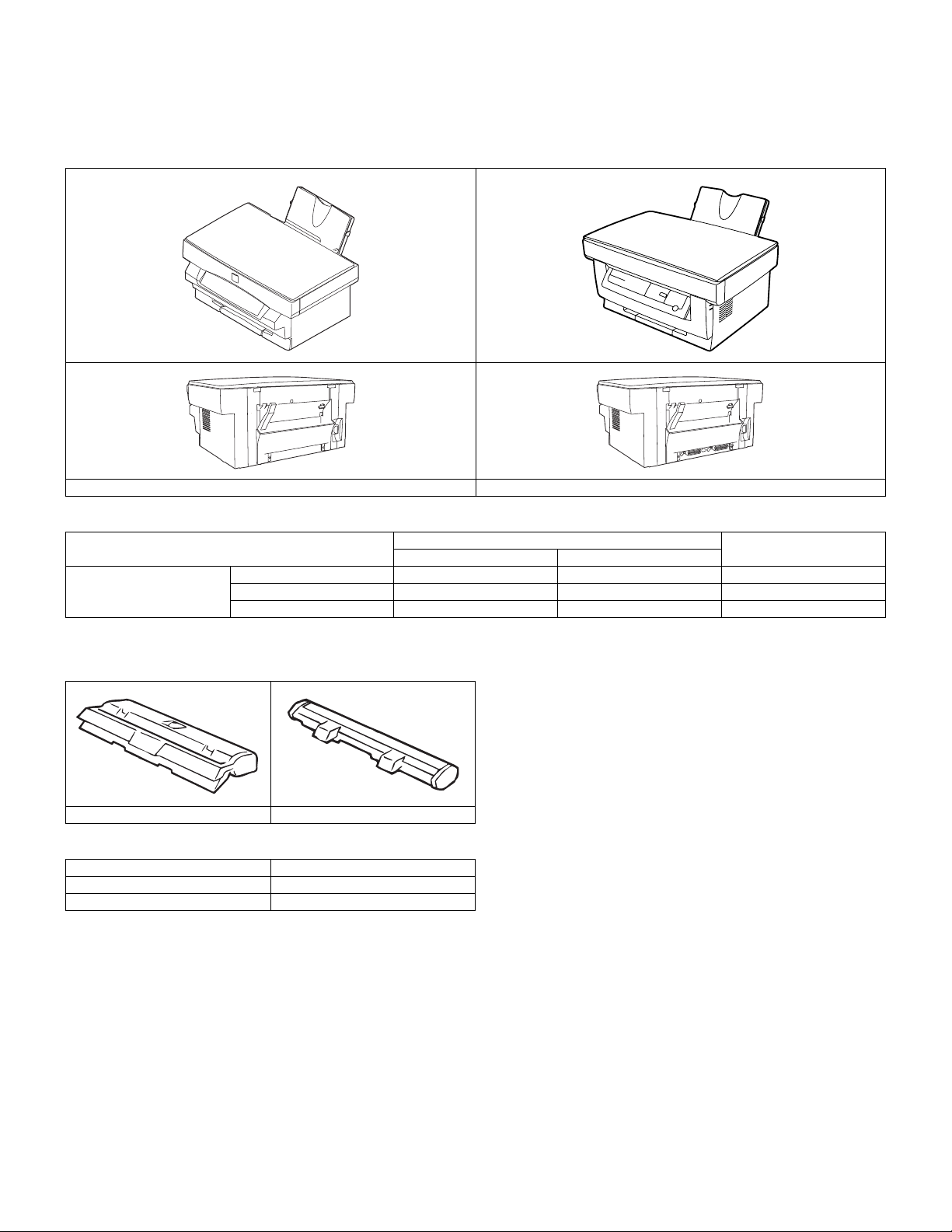
A. Main Unit
(1) Appearance
AL-800L/800 AL-840
(2) Function/Equipment
Item
Function/Equipment Copying speed 8 CPM 8 CPM
Printing speed N/A 8 PPM
Paper tray capacity 250 sheets 250 sheets
AL-800L/800 AL-840
Model
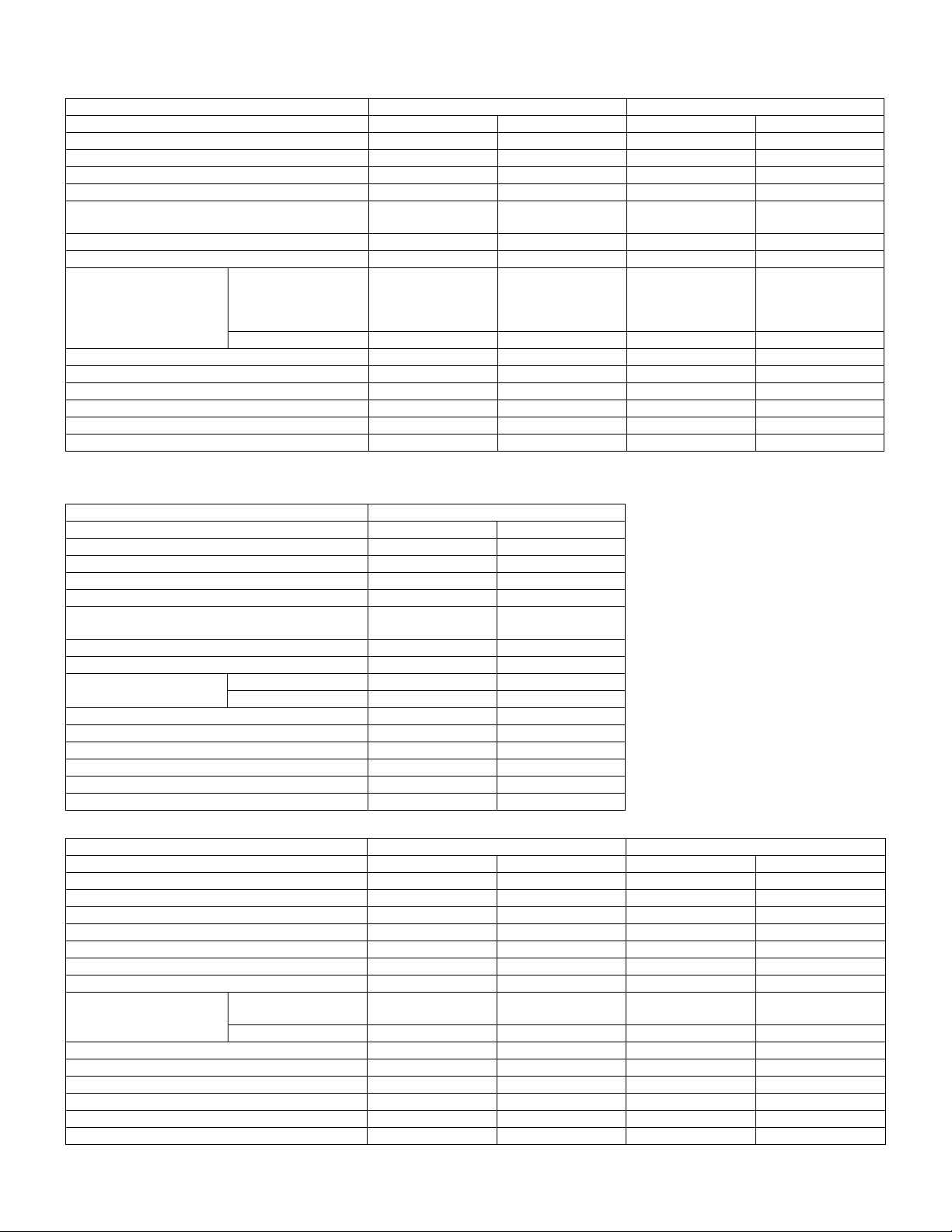
B. Supplies
(1) Appearance
TD cartridge Drum cartridge
(2) Supplies List
Items Model/Parts code
Drum cartridge AL-80DR
TD cartridge AL-80TD
Notes
AL-800L/800/840 SYSTEM CONFIGURATION
1 - 1
Page 5
C. Accessories
Accessories list
EUROPE UK
Model AL-800 AL-840 AL-800 AL-840
Tray (Universal) Included Included Included Included
Drum cartridge Installed Installed Installed Installed
TD cartridge (1.5K) Included Included Included Included
Original cover Included Included Included Included
AC power cord Included
φ4.8 2P
Printer cable N/A Included N/A Included
Driver soft N/A CD-ROM (E) N/A CD-ROM (E)
Operation manual Copier AL-800 (EU)
Included (Multi1*)
Non-EU
Included (Multi2*)
Printer N/A AL-840 Included (E) N/A Included (E)
Warranty card (Registration card) N/A N/A Included (E) Included (E)
MSDS sheets N/A N/A N/A N/A
POP label N/A N/A N/A N/A
Dust cover N/A N/A N/A N/A
User card (Aiyousya card) N/A N/A N/A N/A
Digital logo Included Included Included Included
*Multi1: English, German, Danish, Swedish, French, Dutch, Spanish, Italian
*Multi2: English, German, Danish, French, Russian, Hungarian, Czech, Portuguese
Included
φ4.8 2P
AL-840 (EU)
Included (Multi1)
Non-EU
Included (Multi2)
Included
BS PLG
Included (E) Included (E)
Included
BS PLG
AUSTRALIA/NEW ZEALAND
Model AL-800 AL-840
Tray (Universal) Included Included
Drum cartridge Installed Installed
TD cartridge (1.5K) Included Included
Original cover Included Included
AC power cord Included
Australian PLG
Printer cable N/A Included
Driver soft N/A CD-ROM (E)
Operation manual Copier Included (E) Included (E)
Printer N/A Included (E/F/G)
Warranty card (Registration card) Included (E) Included (E)
MSDS sheets N/A N/A
POP label N/A N/A
Dust cover N/A N/A
User card (Aiyousya card) N/A N/A
Digital logo Included Included
OTHER COUNTRIES (Inch) OTHER COUNTRIES (AB)
Model AL-800L/800 AL-840 AL-800 AL-840
Tray (Universal) Included Included Included Included
Drum cartridge Installed Installed Installed Installed
TD cartridge (1.5K) Included Included Included Included
Original cover Included Included Included Included
AC power cord Included Included Included Included
Printer cable N/A Included N/A Included
Driver soft N/A CD-ROM N/A CD-ROM
Operation manual Copier Included
(Language: TBD)
Printer N/A Included N/A Included
Warranty card (Registration card) N/A N/A N/A N/A
MSDS sheets N/A N/A N/A N/A
POP label N/A N/A N/A N/A
Dust cover N/A (*1) N/A (*1) N/A (*1) N/A (*1)
User card (Aiyousya card) N/A N/A N/A N/A
Digital logo Included Included Included Included
*1: except a part of area
Included
Australian PLG
Included Included Included
AL-800L/800/840 SYSTEM CONFIGURATION
1 - 2
Page 6
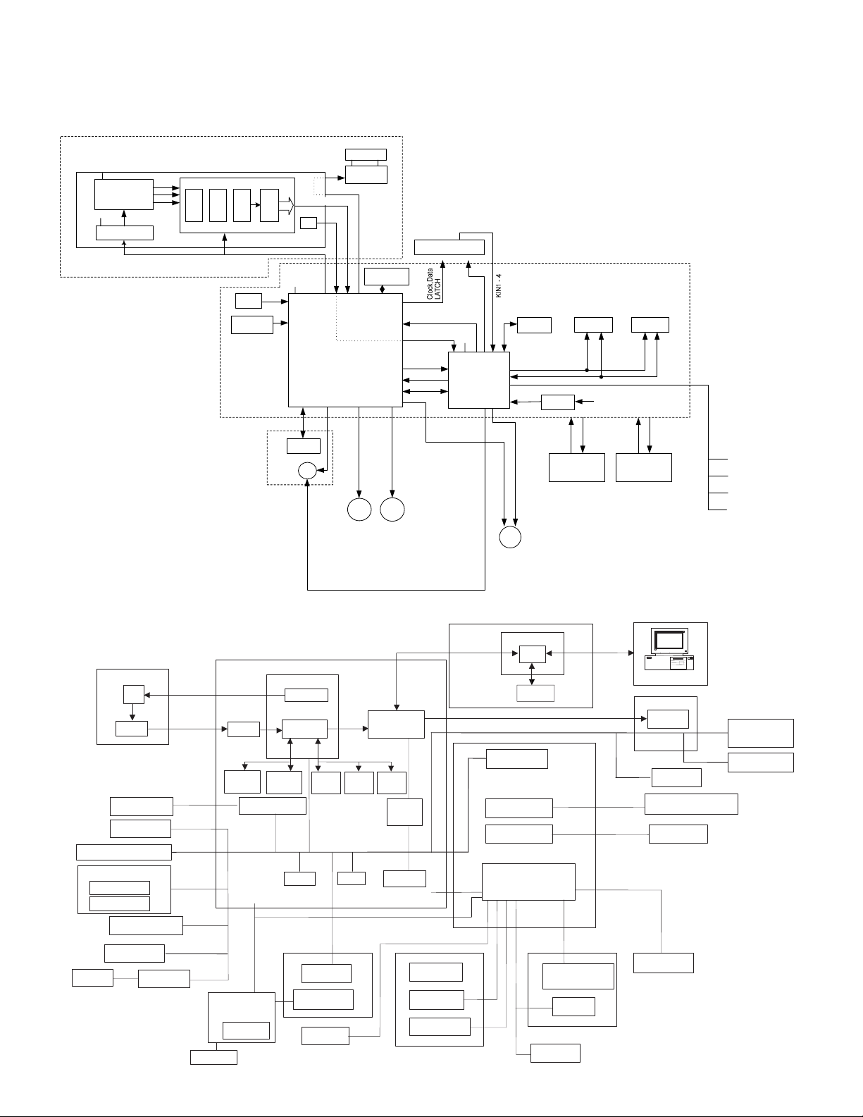
2. Structure
A. Hardware
Block diagram
(AL-800L)
CCD PWB
12V
CCD
5VEN
CCD Driver
CCD_RS,CCD_SHR,CCD _CP,
CCD_CK1,CCD_CK2
R
G
B
AFE(AD9826)
CDS AGC MPX
AD
16bits
MCLK,BSMP,VSMP
AFESEN,AFESCK,AFESDI
OSC
(24MHz)
OSC
(11.8573MHz)
3.3V
CCFL
INV_
Lamp
PWR
Inverter
8bits
MSB/LSB)
FHOME
HP
ASIC
Carriage Unit
VCL
Operation PWB
SDRAM
(64Mb)
MHPS
MIRCNT
A[9
D[15
ASIC Reset
㵺
1]
㵺
0]
SELIN1 - 3
I2C Bus 1Mbit x 1
3.3V
CPU
H8S/2321
(19.9937MHz)
Power Reset
EEPROM
(2kb)
A[19
D[15
0]
㵺
㵺
0]
Reset IC
A[16
㵺
SRAM
(128k
0]
MCU PWB UNIT
8bit)
㬍
D[15
A[19
3.3V
FLASH
ROM
(4Mb)
㵺
8]
0]
㵺
D[15
㵺
0]
(AL-800/840)
CCD PWB
Scanner motor
Home position sensor
Operation panel PWB
Key switch
Display lamp
Paper size sensor
CCD
Amplifier
FAN motor
LSU UNIT
MCU (PCU) PWB
Image process ASIC
A/D
SRAM
SRAM
32kX8
32kX8
Motor driver
Polygon Motor
CCD control
Image
process
3.3V,5V,
12V,24V,
MMD
Main Motor
MMT0/MMT1
ASIC
24V(DSW),
FW
Low Voltage
Power Supply Unit
Laser
FAN MotorScanner Motor
PMCLK
ICU PWB
PROUT
PIN_IN-HLOUT,
High Voltage
Power Supply Unit
/TC,/MC,/PU S,
/PWMSIN
PAPER EXIT SENSOR (POD)
DOOR OPEN SENSOR (DOP)
TONER SENSOR (TS)
THERMISTOR (RTH-IN)
I/F
DRAM
16Mbit
RAMROM
DRAM
16Mbit
Data select
DRAM
16Mbit
CPU
H8S
EEPROM
DRAM
Paper in sensor
Driver
Motor driver
High voltage unit
High voltage
PWB
LSU unit
Laser
Paper exit
sensor
Pickup solenoid
Main motor
Laser beam
sensor
Polygon motor
Scanner
lamp
Toner sensor
Invertor
Power PWB unit
Temperature
Power SW
fuse
Heat roller
Thermistor
Heater lamp
Temperature
fuse
Developer cartridge
Doctor
Developing
roller
Earth sheet
AL-800L/800/840 SYSTEM CONFIGURATION
1 - 3
Main charger roller
Drum
OPC cartridge
Control
electrode
Transfer roller
Page 7
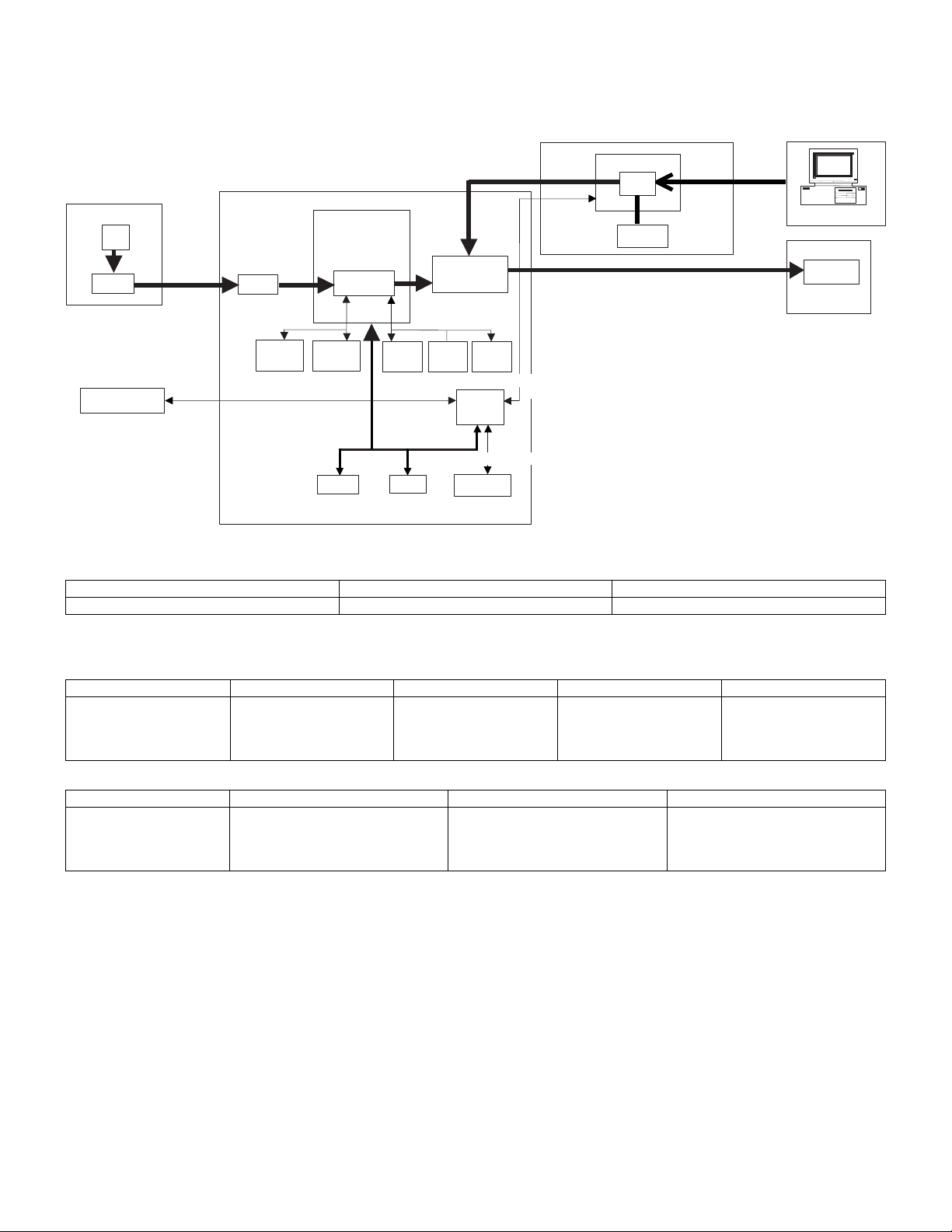
B. Firmware
Block diagram
(AL-800/840)
CCD PWB
CCD
Amplifier
analog
image data
(CCD OUT)
Main control PWB
image data
A/D
(CCDD0~7)
Image process
ASIC
Image
process
image data
Data select
image data(LD)
ASIC
I/F PWB
(VIDEO)
DRAM
image data (V DATA)
I/F
image data
(Data1~8)
LSU unit
Laser
Operation panel
SRAM
32kbitx8
serial data
(OP DATA/KIN1/KIN2)
SRAM
32kbitx8
ROM
DRAM
16Mbit
CPU
RAM
BUS
DRAM
16Mbit
DRAM
16Mbit
serial data
CPU
H8S
serial data (EEPD)
EEPROM
(SDATA)
3. Software (AL-840 only)
Items Contents Media
GDI Printer driver Printer driver CD-ROM
4. Operating environment (AL-840 only)
(1) System requirements
Host computer Operating system Emulation Plug and play Network
IBM PC/AT or
100% compatible
(2) Interface
Type Host computer Operating system Protocol
IEEE1284P x2 IBM PC/AT or 100% compatible MS-DOS 3.3 +
MS-DOS 3.3 +
MS-Windows 3.1X or later
MS-Windows 95/98
MS-Windows NT 4.0
Sleek type GDI Supported Not supported
Peppy
MS-Windows 3.1X or later
Nibble
MS-Windows 95
MS-Windows NT 4.0
AL-800L/800/840 SYSTEM CONFIGURATION
1 - 4
Page 8
[2] SPECIFICATIONS
1. Basic specifications
(1) Types
Type AL-800L/800 AL-840
Model type Desktop type
Scanning type Flat bed/Monochrome type
Printing type
(Emulation type)
(2) Target users
Print Volume AL-800L/800 AL-840
Average 200 sheet/month 450 sheet/month
Maximum 500 sheet/month 1,000 sheet/month
(3) Operating environment (AL-840 only)
Printer mode
<1> System requirements
Host computer Operating system Emulation Network
IBM PC/AT or 100%
compatible
<2> Interface
Type Host computer Operating system Protocol
IEEE1284 P
(2 ports)
IBM PC/AT or
100% compatible
(4) Outer dimensions
Packaged 560 x 440 x 385 mm (22.1" x 17.3" x 15.2")
Machine 460 x 425 x 229 mm (18.2" x 16.8" x 9.02")
(5) Weight
Packaged 12.80 Kg (AL-800/840) 11.00 Kg (AL-800L)
Machine 11.00 Kg (AL-800/840) 8.80 Kg (AL-800L)
(6) Machine life
60K prints or 5 years
2. Operation (Performance)
A. Common operation
Warm-up/Jam recovery
a. Warm-up time
Warm-up time after power ON 0 sec
Recovery time from power save mode 0 sec
Jam recovery time 0 sec
b. Jam recovery time
B. Copy mode
(1) Max. original size
8-1/2" x 14", A4 (210 x 356 mm)
(2) Exposure mode
Exposure mode Steps for exposure Toner save mode
Automatic — Available
Manual 5 steps Available
Photo 5 steps Non
— Electronic photographic type
— GDI
MS-DOS 3.3 +
MS-Windows 3.1X or later
MS-Windows 95/98
MS-Windows NT 4.0
MS-DOS 3.3 +
MS-Windows 3.1X or later
MS-Windows 95/98
MS-Windows NT 4.0
Sleek type
GDI
Not
supported
Peppy
Nibble
(3) Copy ratio
Copy ratio Zoom ratio range/fixed ratio
Zoom mode 50% to 200% (151 steps in 1% increments)
Fixed ratio mode
(AB system)
Fixed ratio mode
(Inch system)
Zooming accuracy Same size copying: 100% ± 1.0%
50, 70, 86, 100, 141, 200%
50, 64, 78, 100, 129, 200%
Enlargement copying : Set copy ratio ± 1.0%
Reduction copying: Set copy ratio ± 1.0%
(4) Job speed
a. First copy time
Mode AL-800L AL-800/840
Normal mode 12.5 sec 12.5 sec
Preheat mode 25 sec 21 sec
Auto power shut-off mode 40 sec 23 sec
b. Copying speed for each paper size and reduction/enlargement
(CPM)
Copy ratio
Paper size
A4
(Short edge feed)
B5
(Short edge feed)
8-1/2" x 14"
(Short edge feed)
8-1/2" x 11"
(Short edge feed)
Same size
8 CPM 8 CPM 8 CPM
8 CPM 8 CPM 8 CPM
7 CPM 7 CPM 7 CPM
8 CPM 8 CPM 8 CPM
Reduction
(50% to 99%)
Enlargement
(101% to 200%)
(5) Max. number of continuous copies
50 copies
(6) Exposure
a. Exposure mode/Processing
Exposure mode Function
Automatic Error diffusion
Manual Error diffusion
Photo Error diffusion
b. Toner save
Yield of Toner save mode 5% area coverage
(When using 3K toner cartridge)
c. Zooming type
Main scanning direction Software computation
Sub scanning direction Scanning speed
d. Resolution
∗ Scanning
(AL-800L)
Main scanning direction Sub scanning direction
Standard resolution
Copier 600 dpi — Copier 300 dpi —
(AL-800/840)
Main scanning direction Sub scanning direction
Standard resolution
Scanner 400 dpi — Scanner 600 dpi —
Copier 400 dpi — Copier 600 dpi —
Virtual
resolution
Virtual
resolution
Standard resolution
Standard resolution
Virtual
resolution
Virtual
resolution
AL-800L/800/840 SPECIFICATIONS
2 - 1
Page 9
∗ Printing
Main scanning direction Sub scanning direction
Standard
resolution
Virtual
resolution
Standard
resolution
600 dpi — 600 dpi —
Virtual
resolution
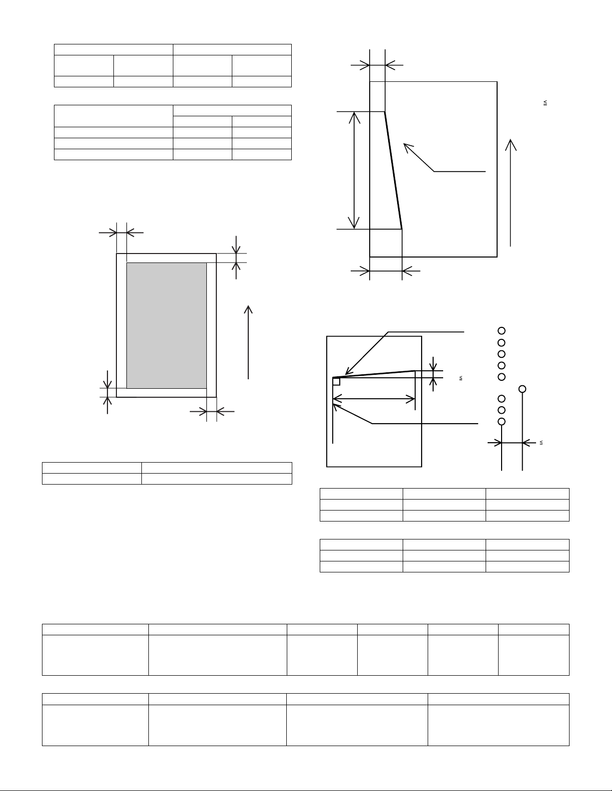
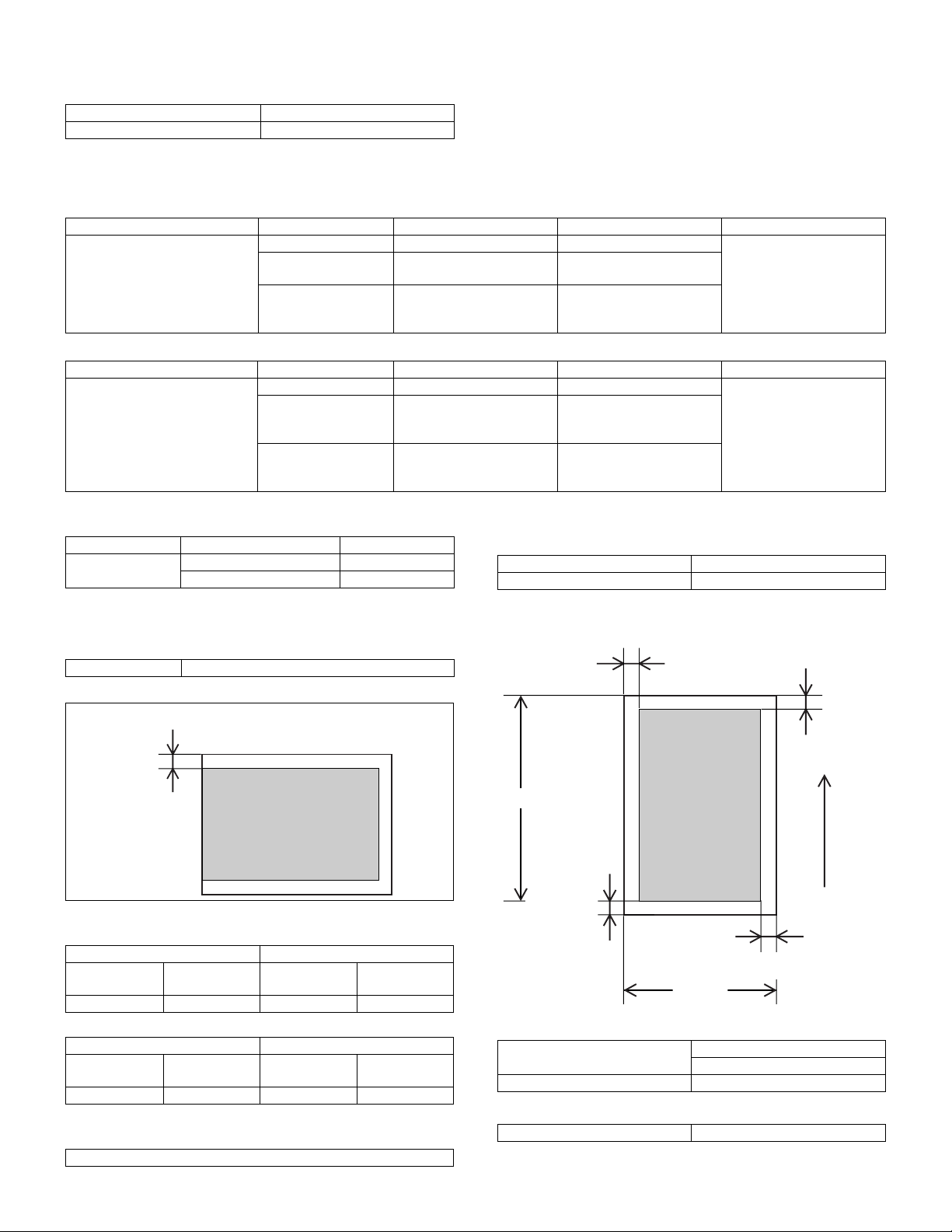
h. Skew (Diagonality)
D1
Copy ratio
Position
Center Corner
Same size 5.0 line/mm 4.5 line/mm
Enlargement (101% to 200%) 5.0 line/mm 4.5 line/mm
Reduction (50% to 99%) 4.0 line/mm 4.0 line/mm
e. Exposure gradient
Error diffusion method.
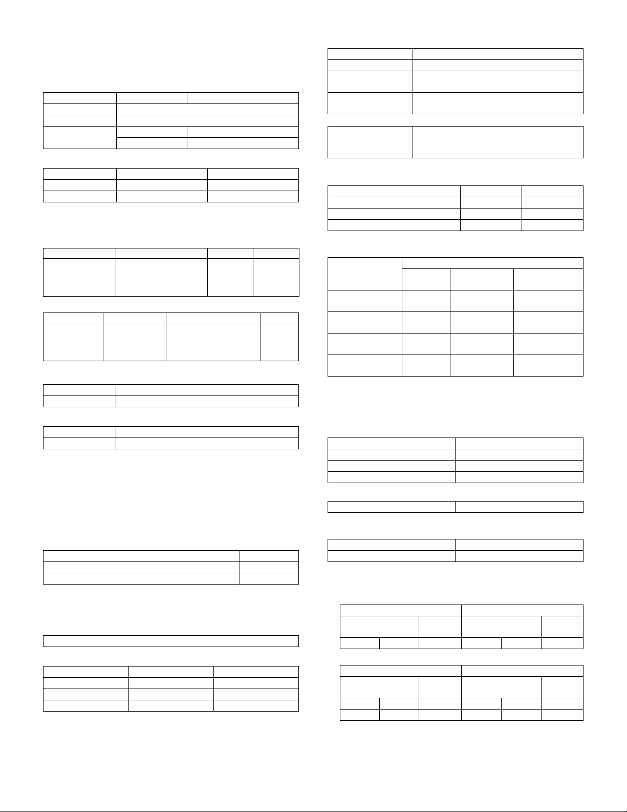
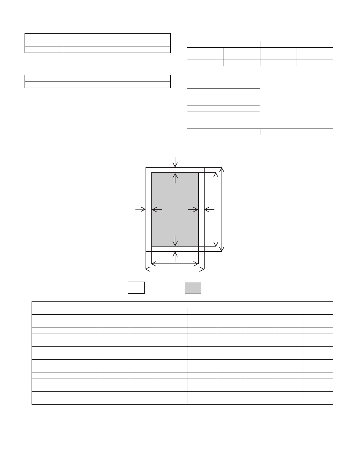
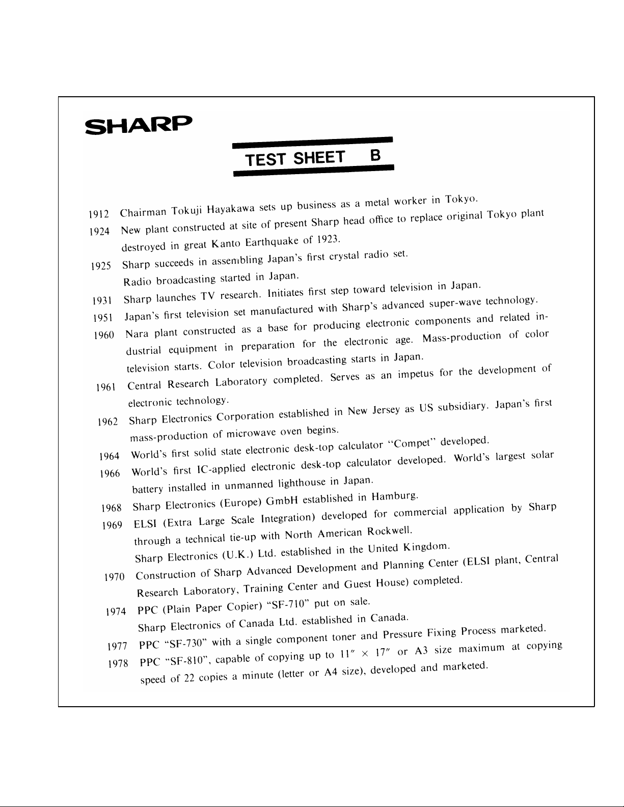
f. Copy (Print) Area
2.0 mm (Std)
3.0 mm (Max)
(Top)
Printed image
(printable area)
2.5 mm (Std)
5.0 mm (Max)
(Bottom)
2.0 mm (Std)
3.0 mm (Max)
g. Image misalignment
Off center 0 ± 2.0 mm or below
Horizontal misalignment 0 ± 2.0 mm or below
1 ~ 5.0 mm
Paper
transfer
direction
| D1-D2 |
269mm
Printed vertical line
D2
Paper
transfer
direction
i. Distortion
Orthogonality Image phase misalignment
Print horizonal line
D
1mm
| D |
203mm
Printed vertical line
60µm
j. Original size
Minimum Maximum
AB system A6 (105 x 148.5 mm) A4 (210 x 297 mm)
Inch system 3-7/8" x 5-7/8" 8-1/2" x 14"
k. Paper size
Minimum Maximum
AB system A6 (105 x 148.5 mm) A4 (210 x 297 mm)
Inch system 3-7/8" x 5-7/8" 8-1/2" x 14"
1.7mm
C. Printer mode (AL-840 only)
(1) System requirements
a. Operating conditions
Host computer Operating system Emulation Driver Plug and play Network
IBM PC/AT or
100% compatible
b. Interface
Type Host computer Operating system Protocol
IEEE1284 P x 2 IBM PC/AT or 100% compatible MS-DOS 3.3 +
MS-DOS 3.3 +
MS-Windows 3.1X or later
MS-Windows 95/98
MS-Windows NT 4.0
Sleek type GDI GDI printer driver Supported Not supported
MS-Windows 3.1X or later
MS-Windows 95/98
MS-Windows NT 4.0
AL-800L/800/840 SPECIFICATIONS
2 - 2
Peppy
Nibble
Page 10
(2) Job speed
a. First print time
Mode Paper feed mode
Normal 20 sec
Power save 20 sec
(A4 (8-1/2" x 11"), Not including the communication time to the host
PC and the set up time of polygon mirror)
b. Print speed
Paper size
8 ppm (A4, 8-1/2" x 11", Sharp standard paper)
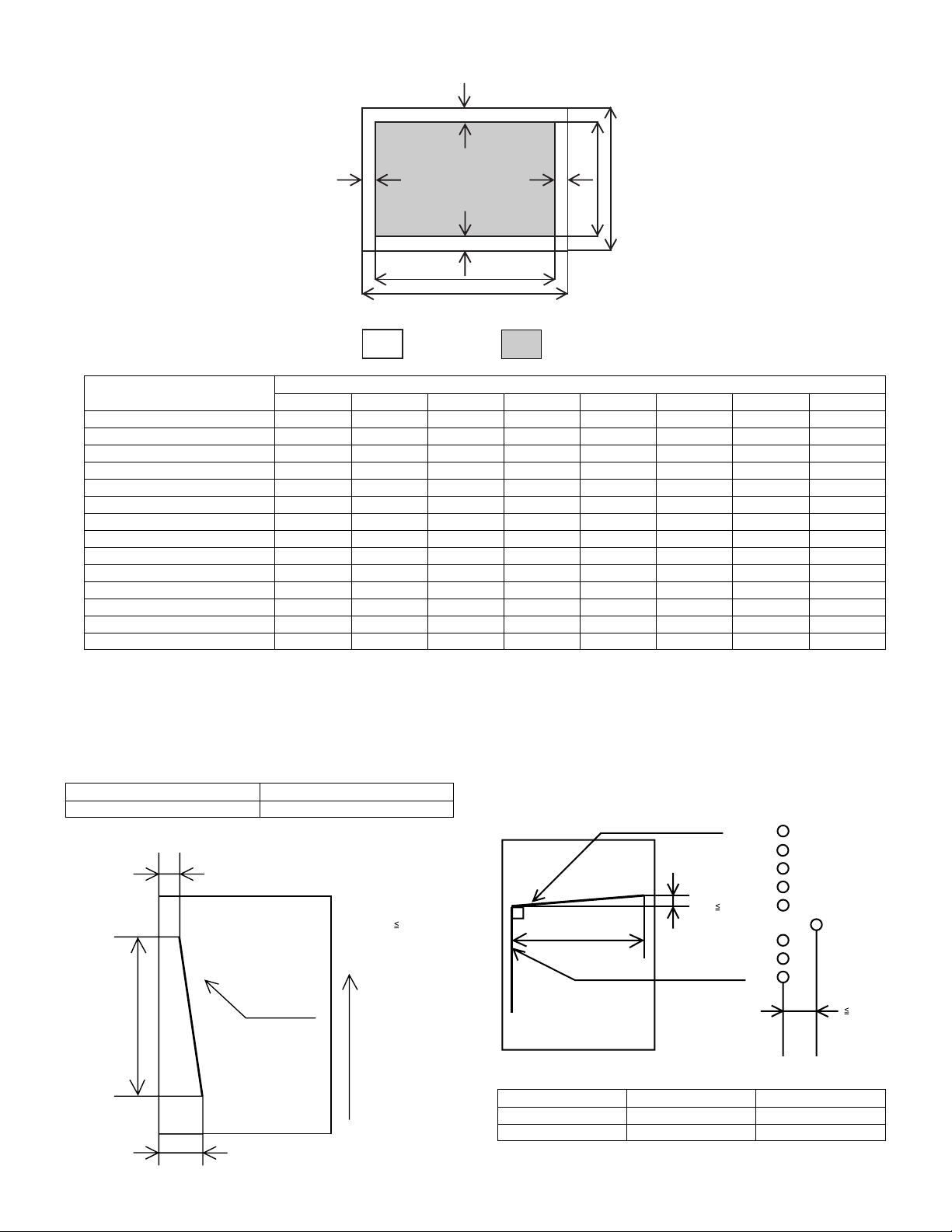
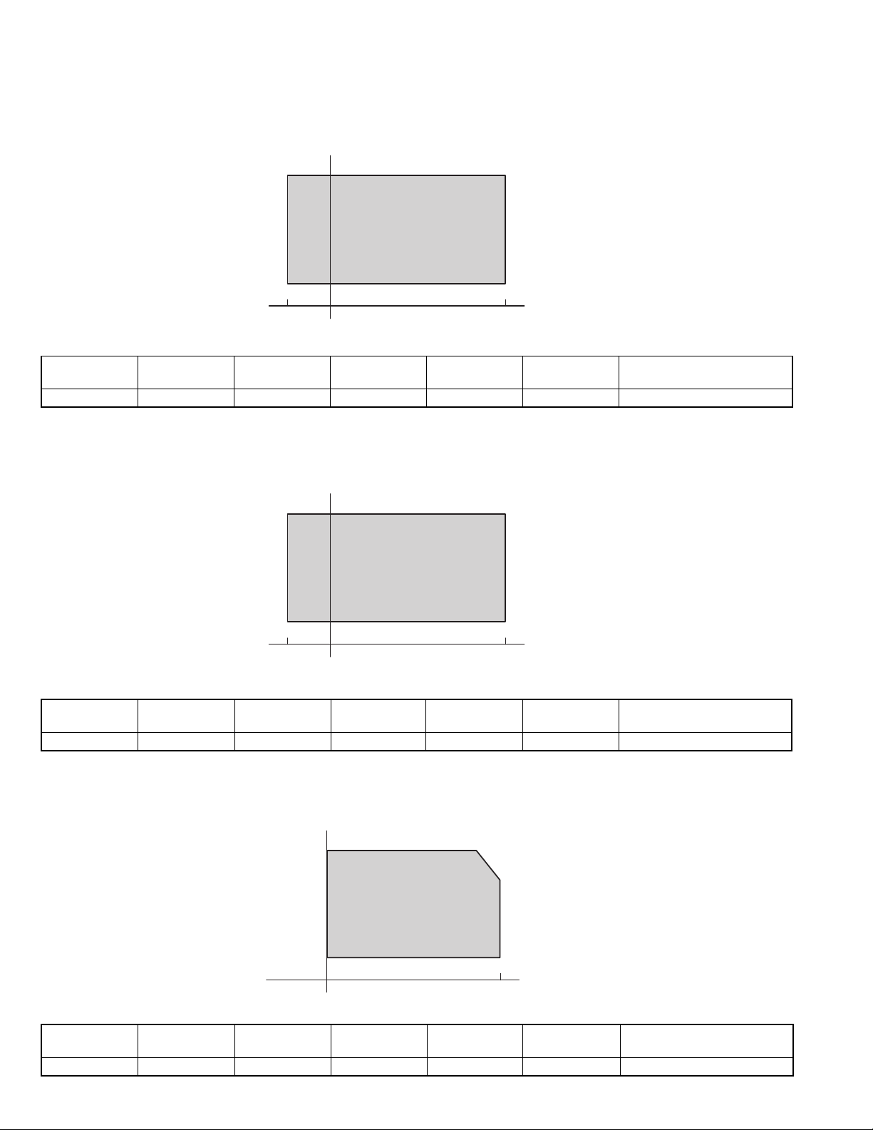
e. Print area
(Portrait)
(3) Image quality
a. Resolution
∗ Printing
Main scanning direction Sub scanning direction
Standard
resolution
600 dpi* — 600 dpi* —
b. Gradient
Gradient
Binary (Dither pattern method)
c. Image treatment
Image treatment
Dither pattern method
d. Toner save
Yield of toner save mode 5% area coverage
G
Virtual
resolution
Standard
resolution
Virtual
resolution
* 300 dpi selectable
E
D
F
B
H
C
A
Physical Page
Paper size
LETTER 2550/5100 3300/6600 2456/4904 3200/6400 50/100 44/96 50/100 50/100
LEGAL 2550/5100 4200/8400 2456/4904 4100/8200 50/100 44/96 50/100 50/100
EXECUTIVE 2175/4350 3150/6300 2080/4152 3050/6100 50/100 45/98 50/100 50/100
A4 2480/4960 3507/7015 2384/4760 3407/6815 50/100 46/100 50/100 50/100
A5 1748/3496 2480/4960 1648/3296 2380/4760 50/100 50/100 50/100 50/100
COM-10 1236/2473 2850/5700 1136/2280 2750/5500 50/100 50/93 50/100 50/100
MONARCH 1161/2323 2250/4500 1064/2128 2150/4300 50/100 47/95 50/100 50/100
C5 1912/3825 2703/5407 1816/3632 2603/5207 50/100 46/93 50/100 50/100
DL 1299/2598 2598/5196 1200/2400 2498/4996 50/100 49/98 50/100 50/100
B5 2149/4299 3035/6070 2056/4104 2935/5870 50/100 43/95 50/100 50/100
FOOLSCAP 2550/5100 3720/7440 2456/4904 3620/7240 50/100 44/96 50/100 50/100
FOLIO 2550/5100 3900/7800 2456/4904 3800/7600 50/100 44/96 50/100 50/100
Government Printed Postcard 1181/2362 1748/3496 1088/2168 1648/3296 50/100 43/94 50/100 50/100
Japanese Envelop (Choukei 3) 1417/2834 2775/5551 1320/2640 2675/5351 50/100 47/94 50/100 50/100
A. Physical page width
B. Physical page height
C. Logical page width
D. Width difference between Physical page and HP-GL-2 picture
frame
A B C D E F G H
Logical Page
Value
E. Height difference between Physical page and Logical page
F. Height difference between Physical page and HP-GL-2 picture
frame
G. Printable width
H. Distance between Top edge and Bottom edge in Physical page
AL-800L/800/840 SPECIFICATIONS
2 - 3
Page 11
(Landscape)
G
EF
B
D
H
C
A
Paper size
Physical Page
A B C D E F G H
Logical Page
Value
LETTER 3300/6600 2550/5100 3200/6400 2456/4904 50/100 50/100 50/100 44/96
LEGAL 4200/8400 2550/5100 4100/8200 2456/4904 50/100 50/100 50/100 44/96
EXECUTIVE 3150/6300 2175/4350 3050/6100 2080/4152 50/100 50/100 50/100 45/98
A4 3507/7015 2480/4960 3407/6815 2384/4760 50/100 50/100 50/100 46/100
A5 2480/4960 1748/3496 2380/4760 1648/3296 50/100 50/100 50/100 50/100
COM-10 2850/5700 1236/2473 2750/5500 1136/2280 50/100 50/100 50/100 50/93
MONARCH 2250/4500 1161/2323 2150/4300 1064/2128 50/100 50/100 50/100 47/95
C5 2703/5407 1912/3825 2603/5207 1816/3632 50/100 50/100 50/100 46/93
DL 2598/5196 1299/2598 2498/4996 1200/2400 50/100 50/100 50/100 49/98
B5 3035/6070 2149/4299 2935/5870 2056/4104 50/100 50/100 50/100 43/95
FOOLSCAP 3720/7440 2550/5100 3620/7240 2456/4904 50/100 50/100 50/100 44/96
FOLIO 3900/7800 2550/5100 3800/7600 2456/4904 50/100 50/100 50/100 44/96
Government Printed Postcard 1748/3496 1181/2362 1648/3296 1088/2168 50/100 50/100 50/100 43/94
Japanese Envelope (Choukei 3) 2775/5551 1417/2834 2675/5351 1320/2640 50/100 50/100 50/100 47/94
A. Physical page width
B. Physical page height
C. Logical page width
D. Width difference between Physical page and HP-GL-2 picture
frame
E. Height difference between Physical page and Logical page
F. Height difference between Physical page and HP-GL-2 picture
frame
G. Printable width
H. Distance between Top edge and Bottom edge in Physical page
f. Image misalignment
Off center 0 ± 2.0 mm or below
Horizontal misalignment 0 ± 2.0 mm or below
g. Skew (Diagonality)
D1
| D1-D2 |
269mm
Printed vertical line
D2
h. Distortion
Orthogonality Image phase misalignment
1.7mm
Paper
transfer
direction
i. Paper size
AB system A6 (105 x 148.5 mm) A4 (210 x 297 mm)
Inch system 3-7/8" x 8-7/8" 8-1/2" x 14"
AL-800L/800/840 SPECIFICATIONS
2 - 4
203mm
Print horizonal line
Printed vertical line
Minimum Maximum
D
| D |
1mm
60µm
Page 12
3. Engine specification
A. Operation/display section
Display type LED display
Operation type Button/switch
B. Paper feed/transfer/finishing
(1) Details of paper feed section
AB system
Paper size Capacity Paper weight Special paper Notes
A4, B5, A5, B6, A6 250 sheets 56 – 80g/m²—Paper guide are to be
200 sheets 81 – 90g/m² Standard
1 sheet 52 – 130 g/m²
Inch system
Paper size Capacity Paper weight Special paper Notes
8-1/2" x 14"
8-1/2" x 11"
8-1/2" x 5-1/2"
8-1/2" x 13"
8-7/8" x 12.4"
250 sheets 15 – 21 lbs. — Paper guide are to be
200 sheets 22 – 24 lbs. Standard
1 sheet 14 – 34 lbs.
(2) Details of finishing
Paper receiving tray
Paper size Paper weight Capacity
A4 (8-1/2" x 11") 52 – 80g/m² (15 – 21 lbs.) 50 sheets
81 – 90g/m² (22 – 24 lbs.) 40 sheets
Under standard condition
C. Scanner (reading) section
(1)
Type Flat bed type/Monochrome
condition
(104 – 130 g/m² is available
for A4 size or smaller.)
condition
(28 – 34.5 lbs. is available
for Letter size or smaller.)
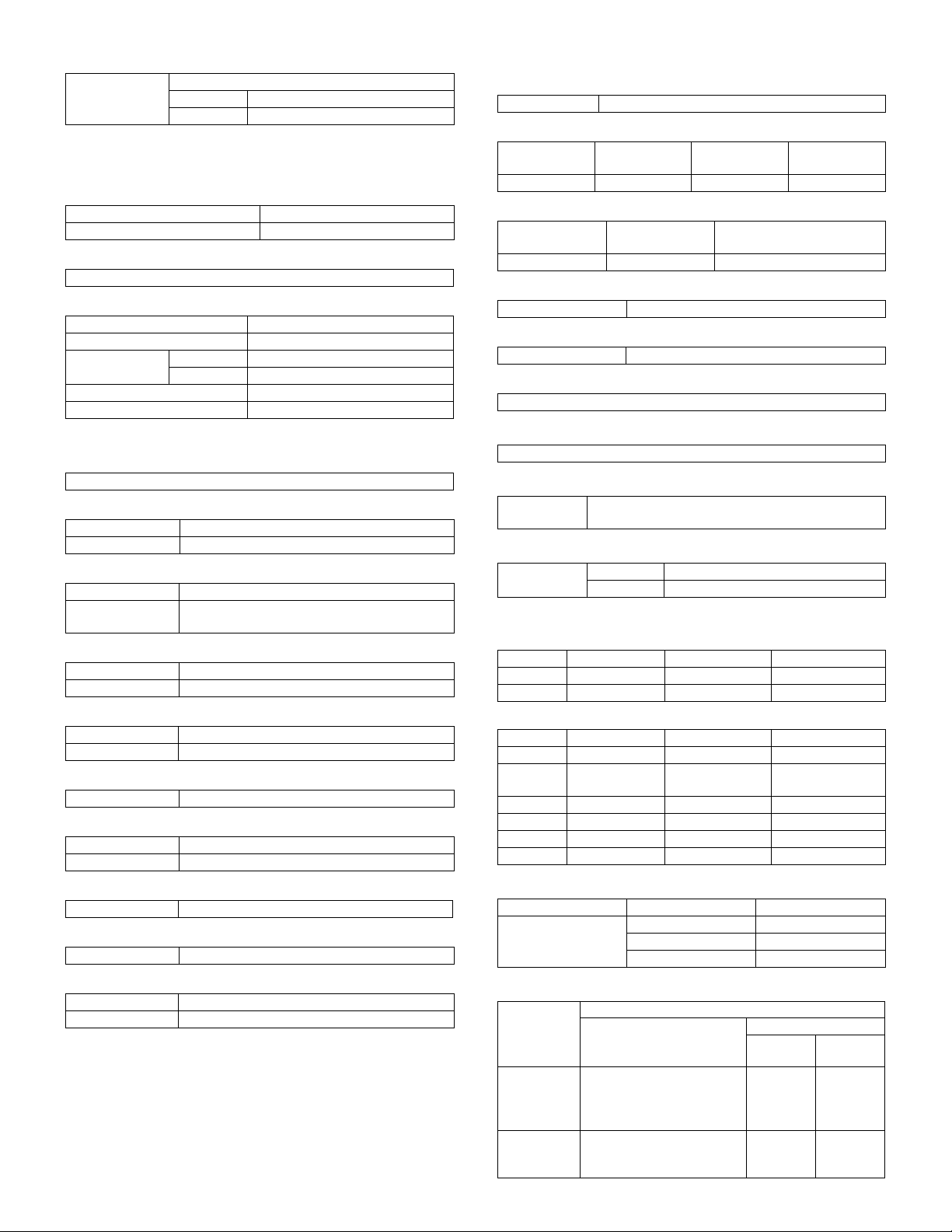
(5) Readable area/size
a. Maximum readable size
(210 x 356 mm)
AB system A4
Inch system 8-1/2" x 14"
b. Scanning area
Recycled paper/
Transparency film/
Label sheet/Envelope
Recycled paper/
Transparency film/
Label sheet/Envelope
—
—
2.0 mm (Std)
3.0 mm (Max)
(2) Original positioning
Top left
changed by user.
changed by user.
(Top)
1 ~ 5.0 mm
4.0 mm
(3) Resolution
(AL-800L)
Main scanning direction Sub scanning direction
Standard
resolution
600 dpi — 300 dpi —
(AL-800/840)
Main scanning direction Sub scanning direction
Standard
resolution
400 dpi — 600 dpi (*) —
Virtual
resolution
Virtual
resolution
Standard
resolution
Standard
resolution
(*) 300 dpi available
(4) Gradient
A/D (8 bit 256 steps)
356 mm
2.5 mm (Std)
5.0 mm (Max)
Virtual
resolution
(6) Scanning speed
Virtual
resolution
100% 50 mm/sec.
(7) Light source (Lamp)
Power voltage AC 800 V (rms) 48 kHz
AL-800L/800/840 SPECIFICATIONS
2 - 5
Copy ratio
Printed image
(printable area)
(Bottom)
216 mm
2.0 mm (Std)
3.0 mm (Max)
Scanning
Speed
Paper
transfer
direction
Page 13
(8) Scanning sensor
Type Reduction optical image sensor (CCD)
AL-800L Color
AL-800/840 Monochrome
D. Scanner (Exposure) section
(1) Type
(2) Resolution
Main scanning direction Sub scanning direction
600 dpi 600 dpi
(3) Gradient
2 steps
(4) Details of Laser unit
Revolution 11,811 rpm
Number of mirrors 6
Laser power AL-800L 0.30 mw
AL-800/840 0.35 mw
Laser beam size 75 x 65 µm
Laser wave length 785 nm
E. Imaging process section
(1) Imaging speed
50 mm/sec.
(2) Photoconductor (Drum)
Type OPC (φ 24 mm)
Life time 20,000 sheets
(3) Toner
Type Developer cartridge color: black
Capacity/Life time 3,000 sheets (1,500 sheets with initially
installed cartridge) (A4 5% cover ratio)
(4) Charging
Method Brush charging method
Voltage DC-850 V AC 600 V (P-P)
(5) Transfer
Method Transfer roller method
Voltage DC+3.5 kV AC 600 V (P-P)
(6) Exposure
Method Semiconductor laser method
(7) Develop
Method Mono component non-magnetic method
Voltage – 310 V
(8) Separation
Method Separation charger type/method
(9) Discharge (Japan only)
Method Discharge brush type
(10) Cleaning
Method By developing roller
Voltage +200 V
AL-800L/800/840 SPECIFICATIONS
F. Fusing
(1)
Method Quick heat-up with pressure roller method
(2) Lamp
Type
Halogen lamp 100/120/230 V 100/120/230 V 500 W
Main unit
power supply
Voltage
(3) Fusing temperature
Ready mode/
Print mode
160°C80°C 155° C
Power save
mode
Print mode (after 20th sheet
in the multi print mode)
(4) Heat roller
Type Teflon coated roller
(5) Pressure roller
Type Silicone rubber roller
(6) Separation method
Forced separation by separation pawl
G. Power drive
Stepping motor (Main motor)
H. Engine control MCU (PCU) (AL-800/840 only)
Processor CPU (H8S2350FP)
ASIC (HG73C025FD)
I. Image control (ICU)
Processor AL-800L ASIC
AL-800/840 ASIC (SLA303TF2B)
J. Memory
(AL-800L)
Type Capacity Contents Location
SDRAM 64 M bit x 1 Copy image data MCU (PCU) PWB
EEPROM 2 K bit Control data MCU (PCU) PWB
(AL-800/840)
Type Capacity Contents Location
DRAM 512 KB Print data ICU PWB
ROM
(EPROM)
DRAM 16 M bit x 3 Copy image data MCU (PCU) PWB
EEPROM 2 K bit Control data MCU (PCU) PWB
SRAM 32 K bytes x 2 Line image data MCU (PCU) PWB
RAM 265 K bit x 2 Work memory MCU (PCU) PWB
1 M bit Program MCU (PCU) PWB
K. Interface (AL-840 only)
Type Items Operating system
IEEE1284P Protocol Peppy/Nibble
Data transfer speed 3 Mbit/sec (Max)
Connector type —
L. Power supply
Output
2 - 6
Type
DC power
supply
High voltage
power
supply
DC +3.5 KV (AC 600 V P-P)
DC – 850 V (AC 600 V P-P)
Voltage
+24 V
+12 V
+5 V
+3.3 V
DC – 310 V (+200 V)
AL-800/
840
2.0 A
0.13 A
1.1 A
0.25 A
—
Power
consumption
Current
AL-800L
1.5 A
0.033 A
0.56 A
0.2 A
Page 14
M. Operating voltage/power consumption
Sub-
sidiaries
—
—
Power
supply
voltage/
frequency
120V
50/60Hz
220 – 240V
50/60Hz
Power
save
mode
29 Wh/h 55 Wh/h 17 Wh/h 170 Wh/h 600 W
35 Wh/h 64 Wh/h 19 Wh/h 175 Wh/h 600 W
(Within Rated voltage ± 10% and Rated frequency ± 2%)
Power consumption
Ready
mode
Power
shutdown
mode
Average
(during
printing)
N. Safety/environmental standard
(1) Safety/environmental standard
(AL-800L)
Item Standard name Country
Safety standard CUL UL USA/Canada
FDA USA
Radio wave noise
standard
(AL-800/840)
Item Standard name Country
Safety standard SEMKO Sweden
Radio wave noise
standard
Energy standard ENERGY STAR World wide
Environmental
standard
(2) Ozon level
Very low (unmeasurable level)
(3) Noise level
Noise mode
Sound power level 66 40 0 dB
Sound
pressure level
FCC USA
NEMKO Norway
DEKRA (GS MARK) Germany
BSI U.K
CUL UL USA/Canada
FDA USA
CE MARK Europe
C-TICK Australia
FCC USA
(Printer only)
——
Individual
Operating
mode
Ready
mode
Power
shut-down
mode
AL-800L 52 dB 35 dB 0 dB
AL-800/840 54.8 dB — 0 dB
Max.
(3) Storage conditions (packed in the packing material)
Humidity
RH
90%
10%
–10˚C50˚C
Humidity
RH
90%
10%
–10˚C40˚C
Machine
40˚C, 90%
50˚C, 60%
Temperature
Supply
40˚C, 90%
Temperature
(4) Transport condition (packed in the packing material)
Humidity
RH
90%
15%
−25˚C40˚C
Machine
30˚C, 90%
40˚C, 60%
Temperature
O. Ambient conditions
(1) Occupied area
Main unit 460 x 650 mm (18.2 x 29.53 in.)
(2) Operating conditions
Humidity
RH
85%
20%
10˚C 35˚C
Temperature
30˚C, 85%
35˚C, 60%
Humidity
RH
90%
10%
(5) Atmospheric pressure
595 mmHg or above
(6) Standard condition
20 to 25°C 65±5% RH, Rating for different countries
AL-800L/800/840 SPECIFICATIONS
2 - 7
Supply
−10˚C40˚C
Temperature
40˚C, 90%
Page 15
[3] CONSUMABLE PARTS
1. Configuration
2. Developer cartridge
No. Part name (Item)
1 Photoconductor cartridge
2 Developer cartridge
1. Photoconductor cartridge
2. List
A. Consumable parts for exclusive use
(Single form)
No. Part name (Item)
1 Photoconductor
cartridge
2 Developer cartridge AL-80TD Developer cartridge 1 3K ∗ 10
Model name
AL-80DR Photoconductor
Parts item Q’ty Life Model name Q’ty
cartridge
Content
1 20K 10
(Compound form)
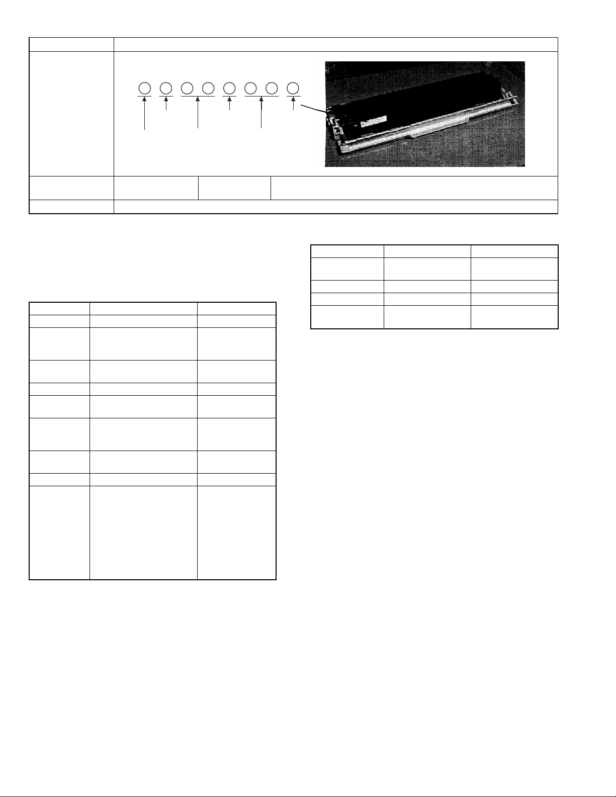
3. Details
(1) Photoconductor drum
Item Specifications/Descriptions
Part name Photoconductor cartridge
Model name
(Single unit)
Model name
(Compound form)
Photo (Picture)
AL-80DR Quantity 1
—
Quantity 10
Note
∗: A4 5% Coverage
Type (Kind) OPC
Form Cartridge
Life Print quantity 20K
Effective use period 36 months from production when sealed, or 20 months when unsealed. (Shorter one, max. 36
months)
AL-800L/800/840 CONSUMABLE PARTS
3 - 1
Page 16
Item Specifications/Descriptions
Weight/Capacity/
Quantity
Weight Single unit Weight (g/kg) 241 g Weight (lbs)
Compound form Wright (g/kg) Weight (lbs)
Quantity Single unit
Compound form
Capacity (Litter)
Applied model AL-800/840
Compatibility
information
Product No. content
Ver.
Version
Production year
(End digit)
Fixed to 1. Form
Serial No. in each
production month
Production
month
0: October
X: November
Y: December
Guarantee period (Month) 24 Counted from the production month. Stored under storage environment
conditions (sealed).
Note
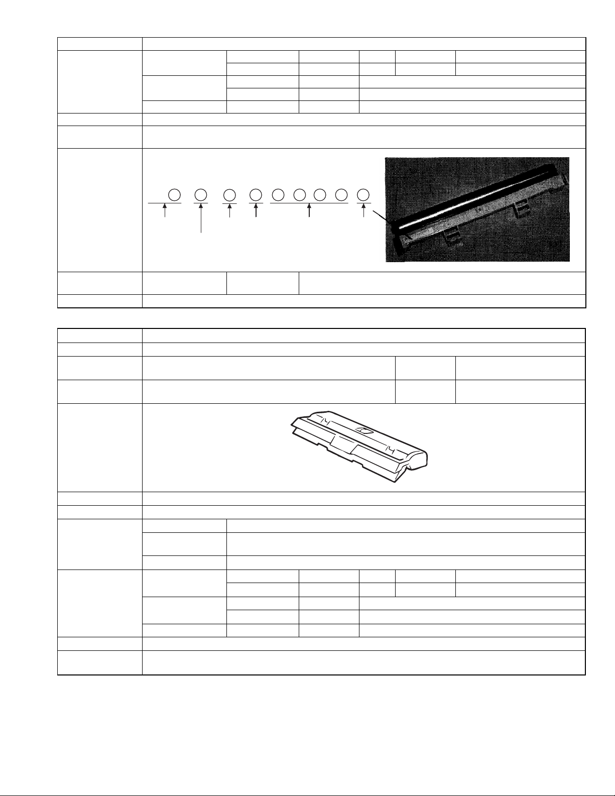
(2) Developer cartridge
Item Specifications/Descriptions
Part name Developer cartridge
Model name
(Single unit)
Model name
(Compound form)
Photo (Picture)
Type (Kind) Mono-component toner
Form Cartridge
Life Print quantity 3K (A4, 5% cover ratio)
Weight/Capacity/
Quantity
Applied model AL-800/840
Compatibility
information
AL-80TD Quantity 1
—
Quantity 10
Effective use period 24 months from the production month when sealed, or 12 months when unsealed. (Shorter one,
max. 24 months)
Others
Weight Single unit Weight (g/kg) 463 g Weight (lbs)
Compound form Wright (g/kg) Weight (lbs)
Quantity Single unit
Compound form
Capacity 80 g
AL-800L/800/840 CONSUMABLE PARTS
3 - 2
Page 17
Item Specifications/Descriptions
Product No. content
Production
place
Production year
(End digit)
Guarantee period (Month) 24 Counted from the production month. Stored under the storage environment
Note Replace when print density becomes low.
Destination
form
Version
Production
day
4. Paper specifications
To assure print quality and normal paper handling, the following
specifications of paper should be satisfied.
(1) Paper
Standard and Applicable Paper
Item Standard paper Applicable paper
Weight 60 – 90 g/m
Smoothness face; ≥ 20 s
Porosity ≥ 7 s
Opacity ≥ 77% same as left
Surface
resistivity
Stiffness vertical; ≥ 17 cm
Moisture
content
Thickness 75 µm – 110 µm same as left
Dimension B5 (182 ± 1 × 257 ± 1mm)
back; ≥ 20 s
(BEKK method)
(BEKK method)
1 × 10
(20 ± 1°C
horizontal; ≥ 13 cm
(CLARK method)
4.5% – 7.0% same as left
B6 (128 ± 1 × 182 ± 1mm)
A4 (210 ± 1 × 297 ± 1mm)
A5 (148 ± 1 × 210 ± 1mm)
A6 (105 ± 1 × 148 ± 1mm)
8.5" ± 5/128 × 14" ± 5/128"
8.5" ± 5/128 × 11" ± 5/128"
5.5" ± 5/128 × 8.5" ± 5/128"
8.5" ± 5/128 × 13" ± 5/128"
(Paper Types That Should Not be Used)
Paper that has any of the following should not be used for printing.
•
Paper with special coating on the surface
•
Paper with particularly rough or smooth surface
•
Paper which has been glued together and which could become
separated.
•
Paper with tears, folds, embossing, dryness, moisture or curl
•
Paper with metal tabs or clips
•
Paper with holes, windows or perforations
•
Paper which has been pre-printed using a laser printer or photocopier
(Note) Before printing, try one of the pieces of paper to be used and
confirm that it can be printed successfully.
10
– 5 × 10
2
10
(Values at 20 ± 1°C, 65 ± 2% RH)
60 – 120 g/m
face; ≥ 20 s
back; ≥ 18 s
(BEKK method)
same as left
65 ± 2% RH)
same as left
same as left
Production
month
0: October
X: November
Y: December
conditions (sealed).
2
(2) Envelope
Size Dimensions Weight
International DL 110 × 220 mm 60 g/m
International C5 162 × 229 mm Same as above
Monarch 3-7/8" × 7-1/2" Same as above
Commercial 10
(business)
4-1/8" × 9-1/2"
(104.78 × 241.3 mm)
Envelopes
Do not use envelopes which have any of the following.
•
Metal tabs, snaps, strings, perforations, windows or holes
•
Open flaps on which adhesive is exposed
•
Glossy surfaces
•
A particularly rough texture or embossing
•
Envelopes made from recycled paper
•
Envelopes that are not flat due to damage, folds or bending, or
which are not straight with square corners
•
Envelopes which are curled
•
Two or more flaps
•
Labels that have already been attached
•
Flaps that have not been folded
•
Creases or folds on the leading edge
•
Adhesive that sticks without moisture when pressed closed
•
Envelopes that stick together due to exposed adhesive
•
Envelopes that have already been printed on in a laser printer
•
Envelopes that expand or shrink without fine creases
•
Envelopes which are inflated with air
2
(16 lbs.) to
2
90 g/m
(24 lbs.)
Same as above
(3) OHP film
A4 (210 × 297 mm) Letter size (8.5" × 11")
AL-800L/800/840 CONSUMABLE PARTS
3 - 3
Page 18
5. Standard density sample
The ratio of the image area for the total area of paper is 5%.
The life of every consumable part is based on this ratio.
Standard density sample
AL-800L/800/840 CONSUMABLE PARTS
3 - 4
Page 19
6. Environmental conditions
(1) Transit environment (sealed)
Max. change: Temperature 15°C/hour, Relative humidity 15%RH/hour, without dew
Humidity
RH
90%
10%
-10°C40°C
Temperature
Temperature
(min)
– 10°C 10% 40°C 90%
Humidity
(min)
Temperature
(mid)
Humidity
(mid)
Temperature
(max)
(2) Storage environment (sealed)
Max. change: Temperature 15°C/hour, Relative humidity 15%RH/hour, without dew
Humidity
RH
90%
40°C, 90%
Humidity
(max)
40°C, 90%
Period
10%
-20°C40°C
Temperature
Temperature
(min)
– 10°C 10% 40°C 90%
Humidity
(min)
Temperature
(mid)
Humidity
(mid)
Temperature
(max)
(Unsealed condition)
Humidity
RH
30°C, 90%
90%
35°C, 60%
10%
0°C35°C
Temperature
Temperature
(min)
0°C 10% 30°C 60% 35°C 90%
Humidity
(min)
Temperature
(mid)
Humidity
(mid)
Temperature
(max)
Humidity
(max)
Humidity
(max)
Period
Period
AL-800L/800/840 CONSUMABLE PARTS
3 - 5
Page 20
[4] SET UP
1. Installing conditions
Improper installation may damage the copier. Please note the following during initial installation and whenever the copier is moved.
CAUTION: If the copier is moved from a cool place to a warm place,
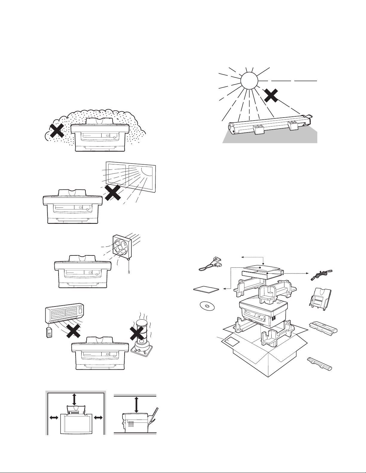
Do not install your copier in areas that are:
•
damp, humid, or very dusty
condensation may form inside the copier. Operation in
this condition will cause poor copy quality and malfunctions. Leave the copier at room temperature for at least 2
hours before use.
CAUTIONS ON HANDLING
Be careful in handling the copier as follows to maintain the performance of this copier.
Do not expose the drum cartridge to direct sunlight.
Doing so will damage the surface (green portion) of the drum cartridge, causing smudges on copies.
•
exposed to direct sunlight
•
poorly ventilated
•
subject to extreme temperature or humidity changes, e.g., near an
air conditioner or heater.
Store spare supplies such as drum cartridges and TD
cartridges in a dark place without removing from the
package before use.
If they are exposed to direct sunlight, smudges on copies may result.
Do not touch the surface (green portion) of the drum
cartridge.
Doing so will damage the surface of the cartridge, causing smudges
on copies.
2. Unpacking
A. packing list
Open the carton and check if the following components and accessories are included.
IBM PC/AT or compatible
machine interface cable (AL-840 only)
Power cord 1 pc.
Operation manual
CD-ROM (Printer driver)
(AL-840 only)
Paper feed tray
Developer cartridge
(Packed in the silver bag.)
Be sure to allow the required space around the machine
for servicing and proper ventilation.
20cm
20cm
10cm 10cm
AL-800L/800/840 SET UP
4 - 1
Warranty paper
Photo conductor cartridge
(Installed in the machine)
Page 21
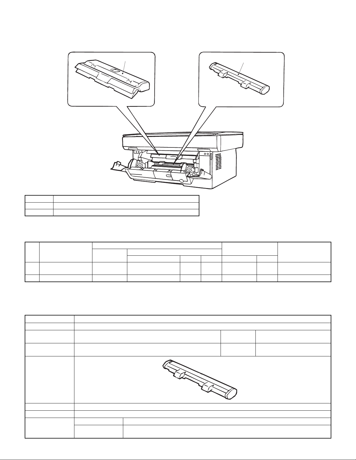
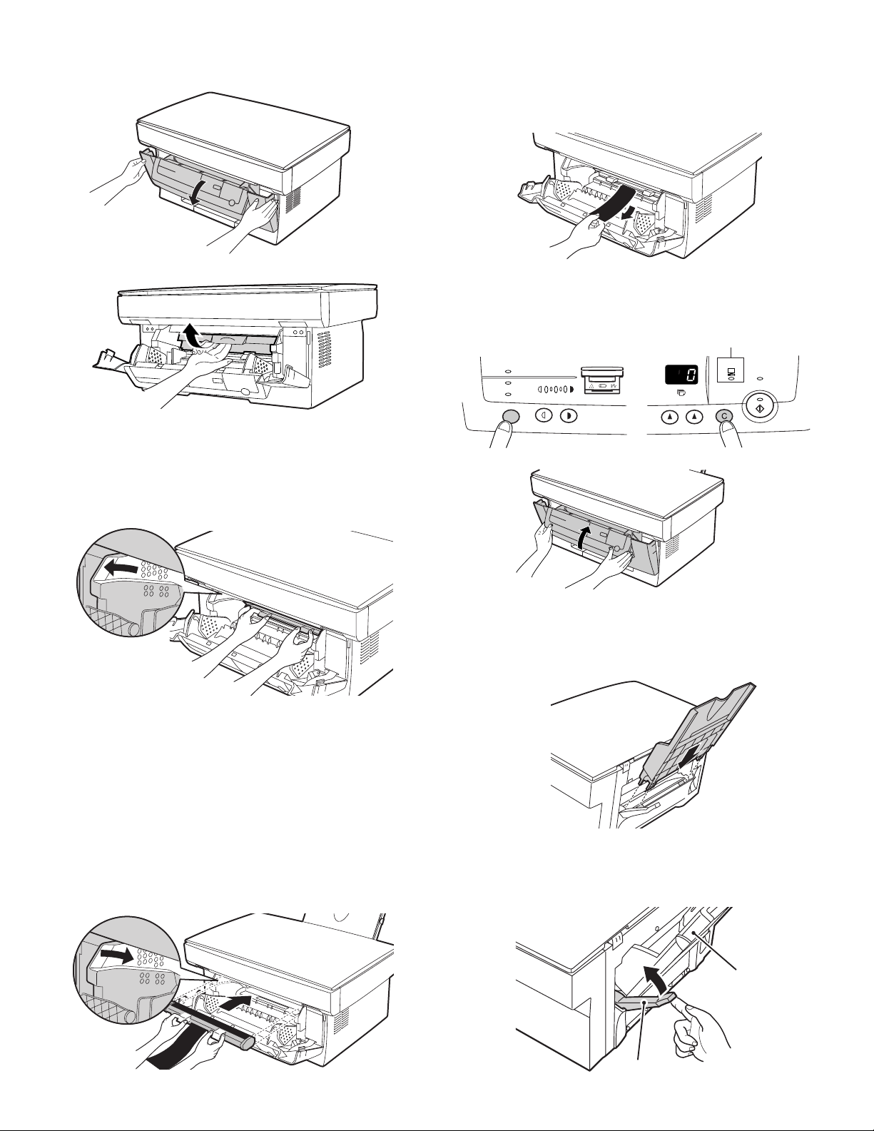
B. Releasing lock
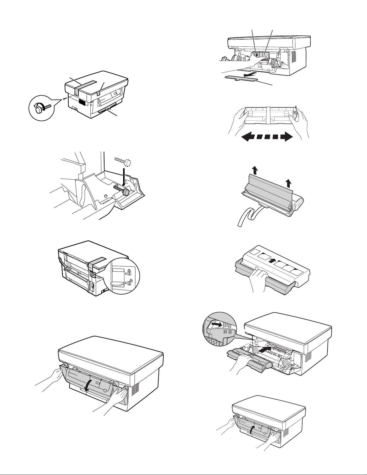
REMOVING PROTECTIVE PACKING MATERIALS
(AL-800/840)
1) Remove tape (a).
2) Turn and remove the lock screw in the arrow direction.
3) Remove the protective material (b).
(a)
(b)
Do not remove with
the front cover closed.
Keep the fixing screw inside the front cover.
(d)
3) Remove the TD cartridge from the bag. Hold the cartridge on both
sides and shake it horizontally four or five times.
(e)
(c)
Store the lock screw at the right side inside the front cover.
(AL-800L)
1) Release the scanner lock lever.
3. Parts and consumable parts setup
CAUTION: Be sure to remove the protective paper from the drum
cartridge before installing the TD cartridge.
4) Remove the protective tape and then the protective cover.
5) Hold the handle of the TD cartridge so that the stamped marking
on top of the cartridge are facing upward.
6) Gently insert the TD cartridge into the copier along the guides in
the direction indicated by the arrow.
(1) Developer cartridge
1) Push gently on both sides of the front cover to open the cover.
2) Remove the protective material (c), and slowly pull the protective
sheet (d) and protective material (e) together toward you to remove. Be careful not to break the protective sheet (d) midway and
not to remain torn part inside the machine.
AL-800L/800/840 SET UP
Align the projections on both side with the guides.
7) Close the front cover.
4 - 2
Page 22
(2) Photoconductor cartridge
1) Gently press the both sides of the front cover and open it.
6) Remove the black protective sheet from the photoconductor cartridge.
CAUTION: If the black protective sheet is pulled forcibly, it may be
broken, Be careful not to break the sheet and slowly
remove it.
2) Slowly remove the developer cartridge from the copier.
3) Hold two knobs of the photoconductor cartridge with your fingers,
and slowly pull out it.
WARNING: The fusing section is heated to a high temperature.
When removing the photoconductor cartridge, be careful
not to touch the fusing section to avoid a burn.
CAUTION: Dispose the photoconductor cartridge as an incombusti-
ble.
7) Install the developer cartridge.
8) Turn on the power switch. While pressing the copy mode select
key and the clear key, open and close the operation panel section.
(The photoconductor counter is reset by the above operation.)
AL-800/840 only
AUTO
MANUAL
PHOTO
135
ONLINE
PREHEAT
(3) Paper tray
1) Hold the paper tray so that the paper guide of the paper tray is
facing front and then insert the paper tray into the copier’s paper
tray slots.
4) Remove a new photoconductor cartridge from the bag.
•
CAUTION:
A black protective sheet is attached to a new
photoconductor cartridge in order to protect the
cartridge from light. Install the cartridge in the copier
with this black sheet attached to it. If it is removed, the
cartridge surface (green section) may be damaged.
•
Keep the photoconductor cartridge in a clean place. If
it is stored in a dusty place, the cartridge surface
(green section) may be damaged to cause a dirt on
print paper.
5) Hold the two knobs of the photoconductor cartridge with your
fingers, and slowly insert the projections on the both ends of the
cartridge into the machine along the guides in the arrow direction.
AL-800L/800/840 SET UP
2) Pull the paper release lever at the right of the paper tray toward
you.
CAUTION: If the paper is inserted without doing this, paper misfeeds
will occur.
Paper tray
Paper reiease lever
4 - 3
Page 23
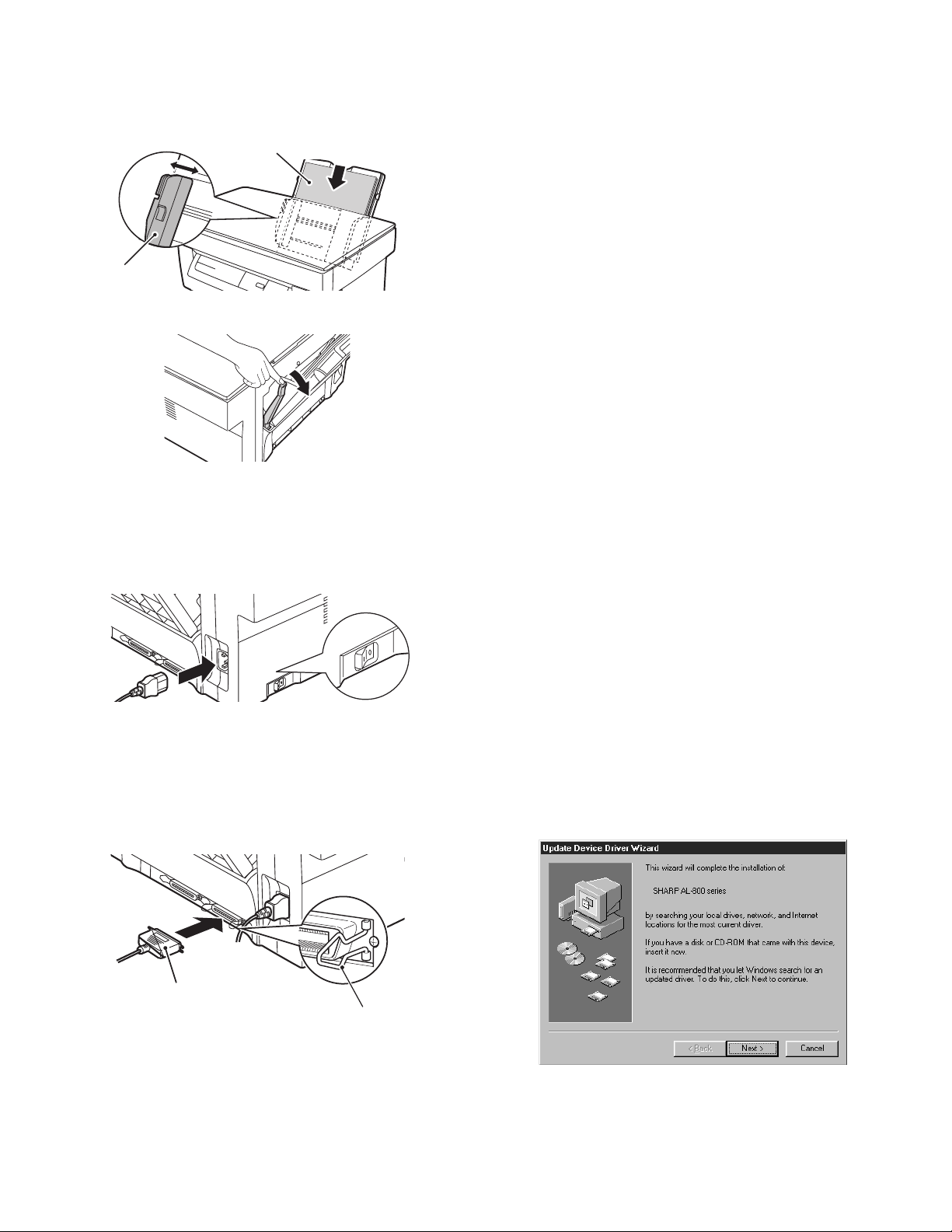
3) If extra-long paper (such as legal size) is used, raise the paper
support to support the paper. Fan the copy paper and place it into
the paper tray with the side to be printed facing toward you. Position the paper along the right end of the paper tray. Then adjust
the paper guide to the paper width.
Side to be printed
Paper guide
4) Make sure the paper release lever is pushed back. The paper will
be clamped by the paper feed roller inside the copier.
4. Cable connection (AL-840 only)
(1) Power cable
Ensure that the power switch of the copier is in the OFF position.
Insert the attached power cord into the power cord socket at the rear
of the copier.
(2) Interface cable
1) Check that the power switches of both the printer and the computer are in the OFF position.
2) Plug the parallel interface cable into one of the printer interface
connectors (whichever connector you want to use). Fasten the two
bail chips at the side of the printer connector to hold the interface
connector in place.
5. Installing the printer driver software
(AL-840 only)
(1) Checking the hardware and software
requirements
You will need the following hardware and software in order to install
the printer driver.
Computer type IBM PC/AT or compatible computer equipped
Windows type Windows 3.1x, Windows 95, Windows 98, Win-
CPU 486DX 66MHz or better
Physical RAM Windows 95, Windows 3.1x: 8 MB (16 MB or
Virtual storage
(swap file)
Display 640 x 480 dots (VGA) or better
Hard disk free space 10 MB or more
CAUTION: The printer driver included in this product cannot be used
under Windows NT3.5x, OS/2, pure MS-DOS and other
operating systems which are not described above.
NOTE: If you are using some of your computers memory as a RAM
drive, the printer driver may not be allocated the correct
amount of memory. In such a case, reduce the size of your
RAM disk, or do not use the RAM disk. Please refer to your
MS Windows documentation for further information.
(2) Install
Windows 95/Windows NT 4.0:
1) Load paper into the paper tray of the printer. For loading of paper,
see the section on LOADING COPY PAPER in the copier operation manual.
2) Turn on the printer.
3) Turn on your computer and start Windows.
NOTE: Before installing the printer driver, be sure to close all other
applications which may be open.
4) When using Windows 95 on a personal computer with plug &
play*, the "Update Device Driver Wizard" window will appear. Insert the installation CD-ROM into the CD-ROM drive. Click the
Next button and follow the on-screen instructions. Proceed to step
7. If the "Copying Files" window appears during this operation,
enter R:\ (if the CD-ROM is designated as drive R) and click the
OK button.
with a bi-directional parallel interface and CDROM
dows NT 4.0
more is recommended.)
Windows 98, Windows NT 4.0: 16MB (32MB or
more is recommended.)
8 MB or more
connecter
Cable
Interface connector
Bail clip
3) Plug the other end of the cable into the parallel interface connector of your computer.
CAUTION: The printer sends and receives data bi-directionally and
at high speed. Some switch boxes and pass-through devices cannot support high-speed, bi-directional transfer
of data, and using them may cause printing errors.
CAUTION: Some printer selectors (which allows to use two or more
computers and printers by selection) are not compatible
to this machine.
AL-800L/800/840 SET UP
4 - 4
•
If you use Windows 95 and the "New Hardware Found" window
will appear, click the Driver from Disk Provided by Hardware
Manufacturer button and then click OK. Proceed to step 6.
•
If you use Windows 95 and the screen shown above or the
"New Hardware Found" window does not appear, proceed to
step 5.
Page 24
•
If you use Windows NT 4.0, proceed to step 5.
★
Plug & play
This feature is effective if both the computer and peripheral
equipment are equipped with IEEE 1284 compliant parallel interface.
NOTE: The screen displayed depends on the version of Windows.
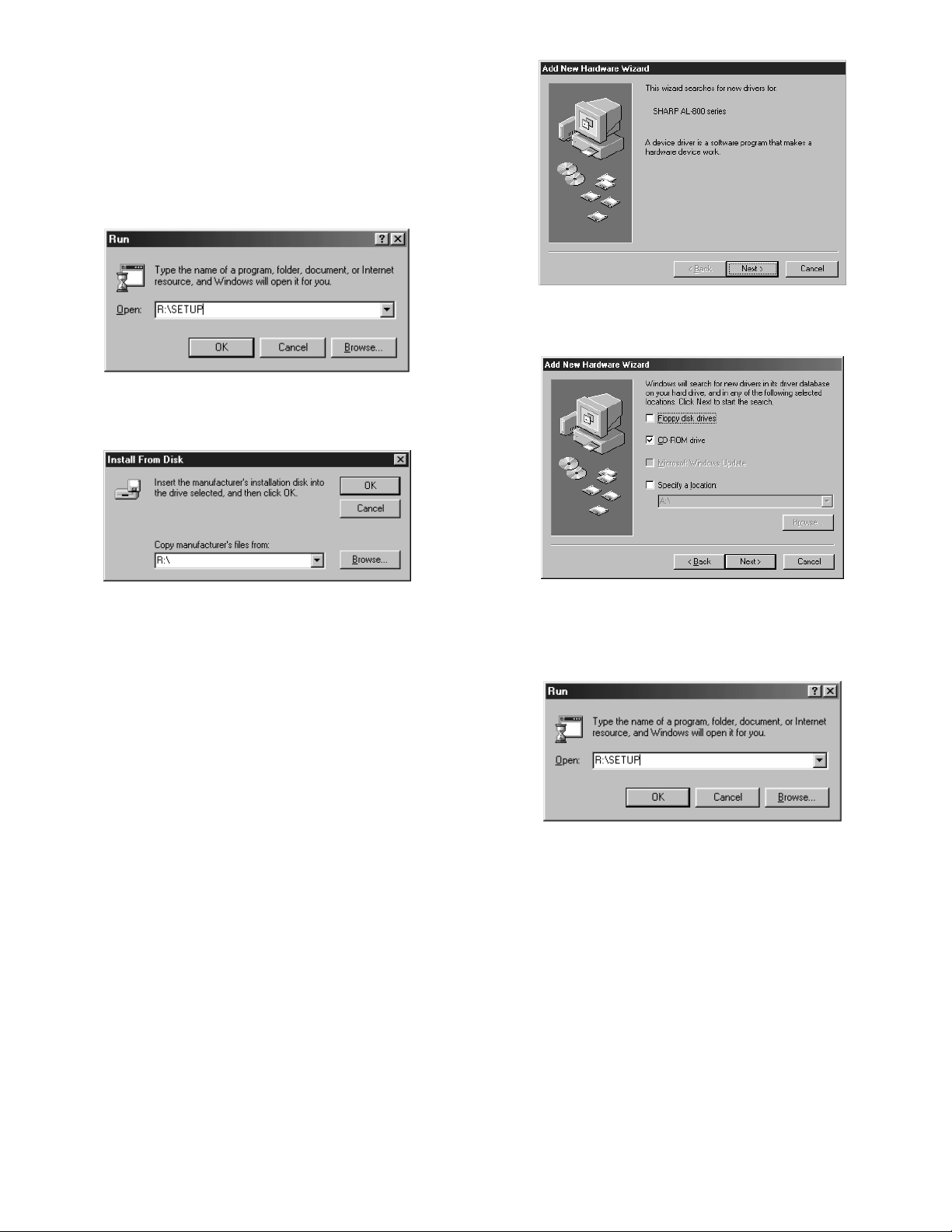
5) Insert the installation CD-ROM into the CD-ROM drive.
Click the Start button and select Run. When the screen shown
below appears, type R:\SETUP (if the CD-ROM is designated as
drive R) and click the OK button. Proceed to step 7.
6) "Install From Disk" window will appear. Insert the installation
CD-ROM into the CD-ROM drive. Type R:\ (if the CD-ROM is
designated as drive R) and click the OK button. Proceed to step
7.
5) Select Search for the best driver for your device and click the Next
button.
6) Insert the installation CD-ROM into the CD-ROM drive. Select the
CD-ROM drive and click the Next button.
7) The installation program will start. To install the printer driver to
the default folder, click the Next button. To select a different
folder, select Browse and type in the new path and folder name.
Click OK and say YES to create the folder, select the Next
button to continue.
8) On the display, you will see "printer port to be used". Normally,
this is LPT1 and it is selected automatically.
Ensure that Yes is checked to use the printer as the default
printer.
Finally click the Next button.
9) A "Confirm installation" window will be displayed. To continue
installation, click the Yes button.
10) When the installation is complete, you will be asked whether or
not to print a test page. If you wish to do so, click the Yes button.
At this time, ensure that paper is loaded in the paper tray.
11) If the test print completes successfully, click the Finish button.
"The installation of the SHARP AL-800 Series Software is complete." window will be displayed. Click the OK button.
Windows 98:
1) Load paper into the paper tray of the printer. For loading of paper,
see the section on LOADING COPY PAPER found in the copier
operation manual.
2) Turn on the printer.
3) Turn on your computer and start Windows.
NOTE: Before installing the printer driver, be sure to close all other
applications which may be open.
4) When using Windows 98 on a personal computer with plug &
play*, the "Add New Hardware Wizard" window will appear. Click
the Next button and follow the on-screen instructions.
•
If the "Add New Hardware Wizard" window does not appear,
proceed to step 8.
Plug &play: For plug & play information, see page 5.
∗
AL-800L/800/840 SET UP
7) Windows driver file search will find the device "SHARP AL-800
Series". Click the Next button. Proceed to step 9.
8) Insert the installation CD-ROM into the CD-ROM drive. Click the
Start button and select Run. When the window shown below appears, type R:\SETUP (if the CD-ROM is designated as drive R)
and click the OK button. Proceed to step 9.
9) The installation program will start. To select a different folder,
select Browse and type in the path and folder name where the
printer driver will be installed. Click OK and say YES to create the
folder, select the Next button to continue. To install the printer
driver to the default folder, click the Next button.
10) On the display, you will see "printer port to be used". Normally,
this is LPT1 and it is selected automatically. Ensure that Yes is
checked to use the printer as the default printer. Finally click the
Next button.
11) A "Confirm installation" window will be displayed. To continue installation, click the Yes button.
12) When the installation is complete, you will be asked whether or
not to print a test page. If you wish to do so, click the Yes button.
At this time, ensure that paper is loaded in the paper tray.
13) If the test print completes successfully, click the Finish button.
"The installation of the SHARP AL-800 Series Software is complete." window will be displayed. Click the OK button.
Windows 3.1x:
1) Load paper into the paper tray of the printer. For loading of paper,
see the section on LOADING COPY PAPER in the copier operation manual.
4 - 5
Page 25
2) Turn on the printer and then start Windows on your computer.
NOTE: Before installing the printer driver, be sure to close all other
applications which may be open.
3) Insert the installation CD-ROM into a CD-ROM drive.
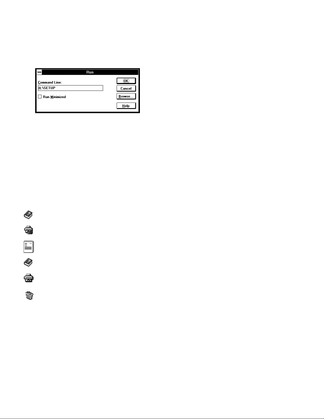
4) Choose File from the Menu bar in Program Manager, and then
choose the Run command.
5) Type R:\SETUP (if the CD-ROM is designated as drive R) in the
command line box and then click the OK button.
6) Select a directory to which the printer driver will be installed and
click the Next button. To install it to the default directory, click the
Next button.
7) A "printer port to be used" window will be displayed. Normally,
LPT1 is automatically set.
Then ensure that Yes is checked to use this printer as the default
printer.
Click the Next button.
8) A "Confirm installation" window will be displayed. To continue installation, click Yes.
9) When the installation is complete, click the Yes button. Then restart Windows.
"AL-800 Series" printer driver group
When the printer driver is installed, the SHARP AL-800 Series printer
driver group will be created. This group allows the following functions
to be executed.
DOS Emulation HELP
DOS Emulation Setup
Readme
The latest information on the printer driver is included in
this note. Read the Readme first.
Status Monitor HELP
Status Monitor
The printer state and information on current printing are
displayed on the status monitor window.
Uninstall AL-800 Series
The printer driver can be uninstalled. If the driver is uninstalled, printing cannot be performed on the printer.
For proper uninstallation, be sure to use uninstallation program of the printer driver group.
(3) Using other installed drivers
If you use another GDI printer or a Windows Printing System printer,
interference between printers may occur and printing may not be
performed properly.
To use another GDI printer or a Windows Printing System printer, you
must change the port setting of the printer driver using the following
procedure.
NOTE: If another printer does not operate properly when the AL-800
series printer driver is set to "FILE", uninstall the AL-800
series printer driver.
Windows 95/Windows 98/Windows NT 4.0:
1) Click the Start button.
2) Select Settings and then click Printers.
3) Right-click the AL-800 Series icon in the printer dialog box and
then click Properties.
4) Click the Details tab (Ports tab – on Windows NT4.0) in the Properties dialog box, select FILE: in the Print to the following port list
box, and click the OK button.
5) Right-click the icon of the printer to be used and click Properties.
6) Click the Details tab (Ports tab – on Windows NT4.0) in the Properties window, select LPT1 (or the currently used port), and click
the OK button.
NOTE: To use the AL-800 series again, perform the same procedure
but select the port to be used (for example, LPT1) in step 4.
Windows 3.1x:
1) Double-click the Control Panel icon in the Main window of Program Manager.
2) Double-click the Printers icon. The Printers window will then open.
3) Select AL-800 Series, and then click the Connect button.
4) Select File from the list of options in the Ports window, and then
click the OK button.
5) Select the new printer you would like to use from the list in the
Installed Printers window, and then click the Connect button.
6) Select the printer port to use for the new printer, and then click the
OK button.
7) Click the Set As Default Printer button, and then click the Close
button.
NOTE: To use the AL-800 series again, perform the same procedure
but select the port to be used (for example, LPT1) in step 4.
(4) Uninstalling printer driver
If the printer driver is not installed properly or if you need not use this
printer any more, uninstall the printer driver from your computer using
the following procedure.
1) If using Windows 95/Windows 98/Windows NT 4.0, click Start,
Program, SHARP AL-800 Series, and Uninstall AL-800 Series.
If using Windows 3.1x, double-click the SHARP AL-800 Series
icon in Program Manager and double-click the Uninstall AL-800
Series icon.
2) When the "Confirm File Deletion" window appears, click the Yes
button.
3) When the "Remove Programs From Your Computer" window appears, click the OK button.
(5) Note for transport
When transporting this machine, follow the following packing procedures before moving.
•
To transport this machine, be sure to use the original packing case
and the protective material.
If another packing case is used, the machine may be damaged.
•
Be sure to remove the developer cartridge before transport.
1. Turn off the power switch and disconnect the power cord.
2. Remove the interface cable from the machine.
3. Gently press the both sides and open the front cover.
4. Remove the developer cartridge from the machine.
5. Remove paper from the paper feed tray.
6. Remove the paper feed tray from the machine.
7. Return the paper feed tray slowly to the bottom.
8. Attach the fixing screw (which is keep inside the machine) to the
left side of the machine.
9. Close the front cover.
10. Attach the protective material and tapes which were removed
when unpacking.
11. Put the machine in the packing case.
AL-800L/800/840 SET UP
4 - 6
Page 26
[5] EXTERNAL VIEW AND INTERNAL STRUCTURE
1. List
A External, operation parts (1) External, operation parts
(2) Internal operation parts
(3) Operation, display parts
B Internal parts (1) Parts in each section a Operation section
b Paper feed, transport section
c Optical section <1> Scanner (reading) section
d Image process section <1> OPC drum section
e Fusing, paper exit section
f Drive section
g Printer section
h Cross sectional view
C Lock position
D Functional parts (1) Sensor, detector
(2) Switch
(3) Clutch, solenoid
(4) Motor a Drive motor
b Fan (motor)
(5) PWB
(6) Fuse, thermostat
(7) Lamp
(8) Interface (connector)
(9) Belt, wire
(10) Power
(11) Adjustment volume
<2> Scanner (writing) section
<2> Developing section
<3> Transfer, separation section
2. Contents
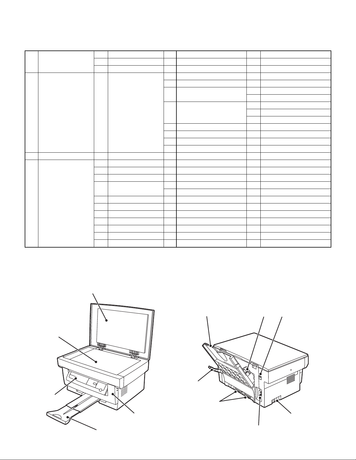
A. External, operation parts
(1) External, operation parts
1)
5)
4)
2)
11)
6)
10)
7)
12)
8)
3)
AL-800L/800/840 EXTERNAL VIEW AND INTERNAL STRUCTURE
5 - 1
9)
Page 27
No.
Name Function/Operation
Parts
Model Note
1 Document cover
2 Front cover Opened when installing or removing the OPC
cartridge and the developer cartridge or
removing a paper jam.
3 Paper exit tray Receives printed paper.
4 Operation panel Allows various setting in the copy mode and test
command operations.
5 Document table A document is set to the left corner reference.
6 Paper feed tray Sets print paper.
7 Paper guide Adjusts the paper width.
8 Power switch Turns on/off the main power.
9 Power connector Connects with the AC power cord.
10 Printer interface connector Connects with the host computer. (Parallel
interface) (IEEE-1284)
AL-840 Allows connection with two host
computers.
11 Paper release lever Put the lever straight when setting paper to
release paper feed drive. Put the lever down to
allow paper feed.
12 Scanner lock lever Locks the scanner unit AL-800L Fixes the scanner unit with this lever
when in transit.
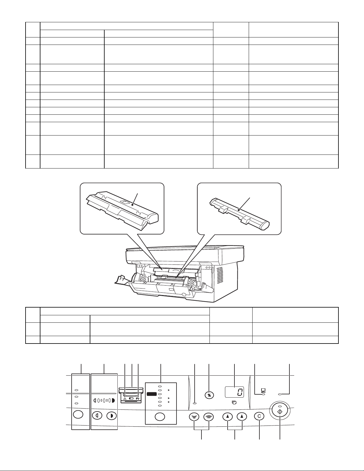
(2) Internal operation parts
1)
No.
Name Function/Operation
1 Developer cartridge Converts latent electrostatic images into visible
Parts
Model Note
Common Life (3K print)
2)
images (toner images).
2 OPC cartridge Forms latent electrostatic images. Common Life (20K print)
(3) Operation, display parts
11)10)9)8)7)6)4)3) 5)2)1)
AUTO
MANUAL
PHOTO
1
35
200%
115%
100%
86%
70%
50%
MAX.
B5
100%
A4 B5
A4
MIN.
A4
A5
ZOOM
ONLINE
PRE-HEAT
(12) (13) (14) (15)
AL-800L/800/840 EXTERNAL VIEW AND INTERNAL STRUCTURE
5 - 2
Page 28
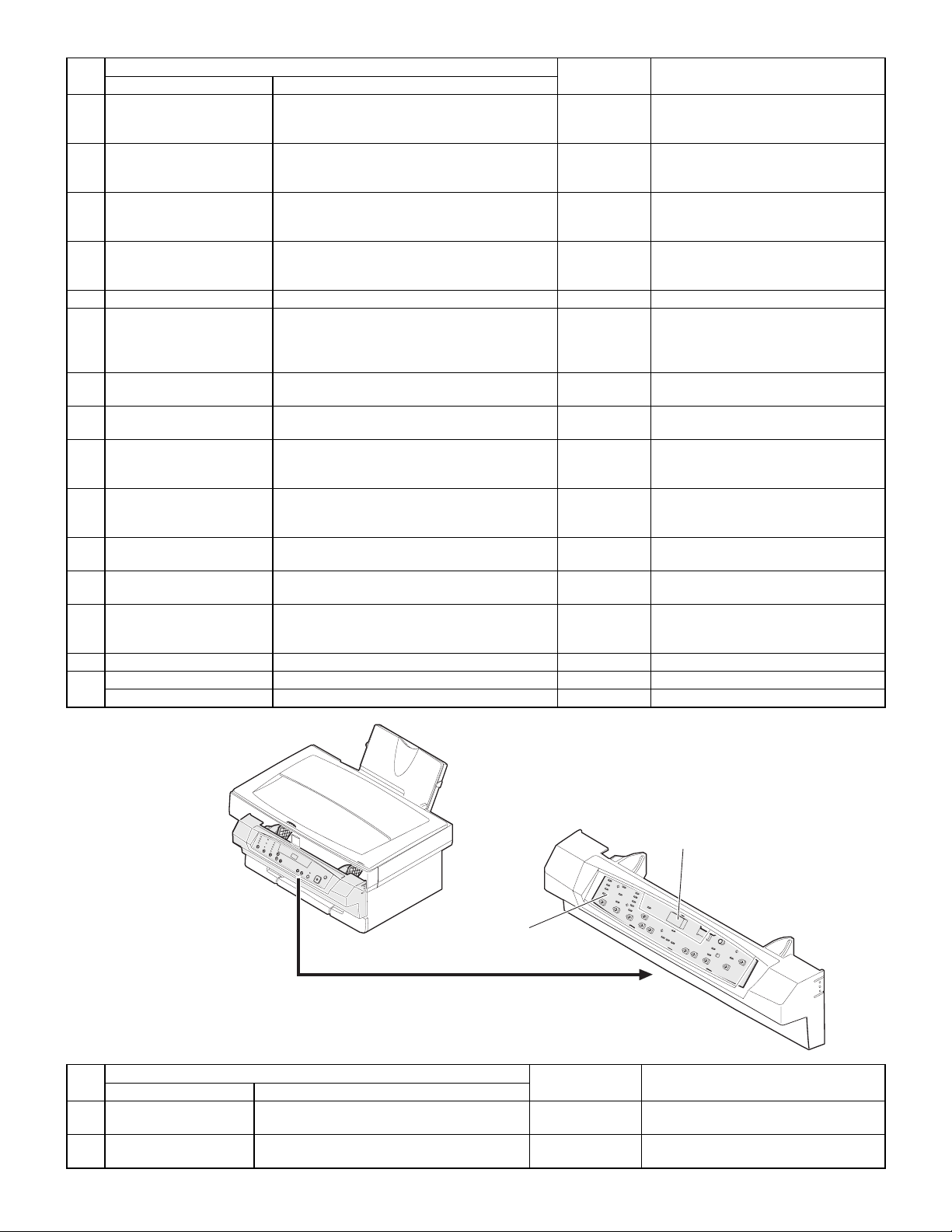
No.
1 Copy image mode select
key/Copy image mode
display lamp
2 Copy density adjustment
key/Copy density level
display lamp
3 Developer cartridge
warning lamp
4 OPC cartridge warning
lamp
5 Paper jam warning lamp Turns on or blinks when there is a paper jam.
6 Copy magnification ratio
select key/Copy
magnification ration display
lamp
7 Zoom mode display lamp Turns on when the zoom key is used to set the
8 Copy magnification display
key
9 Value, code display LED Displays the value information (copy quantity,
10 On-line lamp Turns on during operation in the printer mode.
11 Pre-heat mode display
lamp
12 Zoom key Sets the copy magnification ratio in the range of
13 Value setting key Used to input various set values (copy quantity,
14 Clear key Cancels various setting and operations.
15 Start key Starts operations and stores various set data.
Ready lamp Turns on when in print ready state.
Name Function/Operation
Parts
Selects the copy image mode in auto, character,
photo, toner save mode. Displays the copy
image mode.
Selects the copy density. Used to set the power
save mode. Displays the copy density mode
(level).
Turns on or blinks to show that the consumable
part (developer cartridge) must be replaced.
Turns on or blinks to show that a consumable
part (developer cartridge, OPC cartridge) or that
there is a paper jam.
Selects the copy magnification ratio.
coy magnification ratio.
Used to display the copy magnification ratio set
by the zoom key on the value display.
copy magnification ratio, etc.) and codes (error
code, test command code and its information).
(Print data is received from the host in the
printer enable state or during printing.)
Blinks in the pre-heat mode.
50% ∼ 200% by the increment of 1%.
test command setting, power save mode setting,
etc.). Used to set the power save mode.
Model Note
Turns on when there is little toner, and
blinks when there is no toner to disable
printing.
At 19,000 print, the lamp lights up to
show the life is up. At 20,000 print, the
lamp lights up to disable printing.
AL-840
B. Internal parts
(1) Parts in each section
a. Operation section
No.
1 Operation control PWB Displays various number information and
2 Number display Displays various value information and
Name Function/Operation
Parts
messages. Outputs the key operation signal.
messages.
2)
1)
Model Note
AL-800L/800/840 EXTERNAL VIEW AND INTERNAL STRUCTURE
5 - 3
Page 29
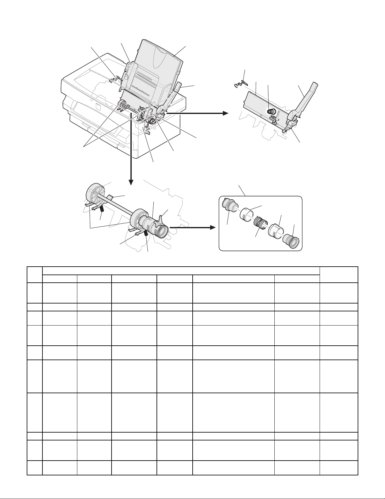
b. Paper feed, transport section
1) PE SENSOR
8)
8)
19)
12)
2)
12)
3)
6)
7) PIN SENSOR
13)
14)
4)
5) PUS
9) PAPER SIZE SW
13)
15)
17)
10)
11)
16)
4)
6)
16)
18)
19)
No.
1 PE SENSOR PEMP IN Paper empty
2 Paper guide Adjust the paper width.
3 Paper feed tray Sets the print paper. (Capacity:
4 Paper release
5 PUS PUS Paper feed clutch
6 Paper feed
7 PIN SENSOR PIN Paper in detector Photo
8 Paper feed roller Feeds paper.
9 PAPER SIZESWPAPER SIZEINPaper width
10 Paper pressure
Code Signal name Name Type Function/operation Active condition
detector
lever
solenoid
release lever
detector
plate
Parts
Photo
transmission
sensor
transmission
sensor
Mechanical
switch (Micro
switch)
Detects paper on the paper tray. LOW (0V) when
XXX sheets)
Put this lever straight to set paper
to release paper feed. Put this
lever down to enable paper feed.
Controls (on/off) the main motor
drive for the paper feed roller.
When the paper feed lever is put
straight, this lever releases paper
feed solenoid drive. This lever
reduces stress to the paper feed
roller clutch in removing paper.
Detects whether the fed paper is
transported to the transfer position
or not. By the timing of this
detector signal, the relative
positions of paper and print image
are controlled.
Detects the paper width. This
signal controls the laser beam
radiation area.
Presses paper onto the paper
feed roller.
paper is detected.
LOW (0V) when
paper is detected.
LOW (0V) when
the max. width is
detected.
Model
AL-800/840
AL-800/840
AL-800L/800/840 EXTERNAL VIEW AND INTERNAL STRUCTURE
5 - 4
Page 30
No.
11 Paper pressure
12 Paper separator Separates paper in paper feed
13 Paper feed clutch Mechanical
14 Paper feed clutch
15 Paper feed clutch
16 Paper feed clutch
17 Paper feed clutch
18 Paper feed clutch
19 Paper separater
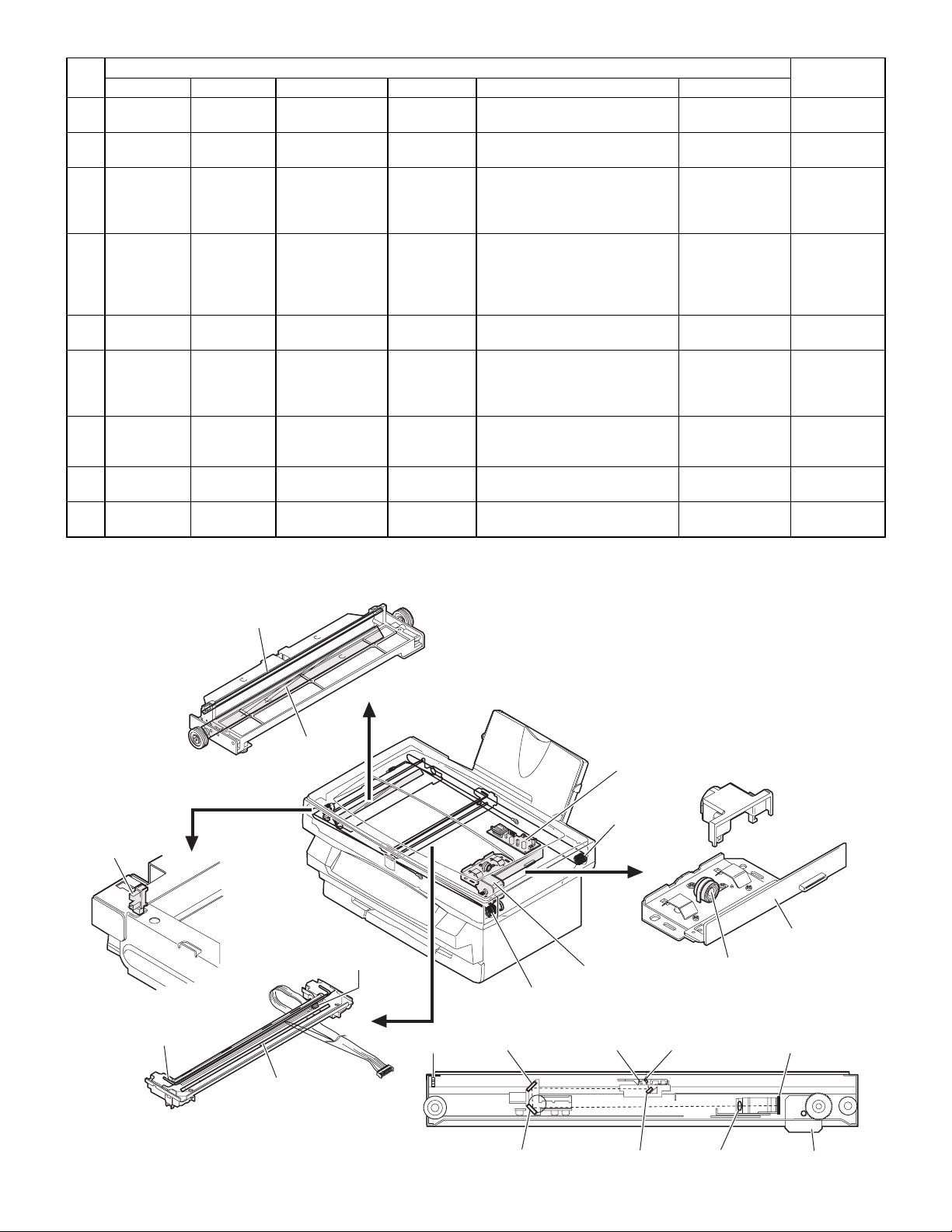
c. Optical section
<1> Scanner (reading) section
(AL-800/840)
Code Signal name Name Type Function/operation Active condition
spring
lever
joint
sleeve
spring
gear
spring
Parts
spring type
clutch
Presses paper onto the paper
feed roller.
operation.
Controls ON/OFF of the paper
feed roller. (The paper feed roller
is driven by the paper feed clutch
solenoid and the main motor.
Driven by the paper feed clutch
solenoid to control ON/OFF of the
paper feed clutch. Prevents
against reverse rotation of the
paper feed roller.
Links the paper feed roller and the
paper feed roller clutch.
Controls ON/OFF of the paper
feed roller. (The paper feed roller
is driven by the paper feed clutch
solenoid and the main motor.)
Transmits the paper feed clutch
rotation to the paper feed clutch
sleeve.
Transmits the main motor power
to the paper reed roller.
Applies a proper pressure to the
paper separater.
Model
4) MHPS
4) MHPS
7)
10)
11)
8) SL SENSOR
4) MHPS
1)
2)
6) CCD SENSOR
3)
5)
2)
10) 8) SL SENSOR 7) 6) CCD SENS
OR
9)
11) 9) 5) 3)
AL-800L/800/840 EXTERNAL VIEW AND INTERNAL STRUCTURE
5 - 5
Page 31

No.
Code Signal name Name Type Function/operation Active condition
1 Scanner lamp
control PWB
Parts
Drives the scanner lamp.
Maintains the lamp light quantity at
a constant level.
2 Scanner drive wire Transmits the scanner motor
power to the scanner unit.
3 Scanner motor Drives the scanner unit.
4 MHPS MHPS Scanner home
position sensor
Photo
transmission
sensor
Detects the scanner home
position. By this signal the image
scanning operation is controlled.
5 Lens Transfers the document image to
CCD.
6 CCD
SENSOR
CCD OUT CCD (Image)
sensor
CCD Scans the document images
(photo signals) and converts them
into electrical signals.
7 Scanner lamp Radiates light to the document to
allow the CCD to scan the
document images.
8 SL SENSOR PDA/PDK Scanner lamp light
quantity sensor
Photo diode Detects the scanner lamp light
quantity. This signal is inputted to
the scanner lamp control PWB to
control the scanner lamp drive
voltage to maintain a constant
level of light quantity.
9 No. 1 mirror Leads the document image to
CCD.
10 No. 2 mirror Leads the document image to
CCD.
11 No. 3 mirror Leads the document image to
CCD.
(AL-800L)
1) CCD SENSOR
3)
Note
HIGH (5V) when
the home position
is detected.
Digital signal
(8Bit)
Analog signal
(0 ∼ 0.5V)
2) MHPS
2) MHPS
1) CCD SENSOR
5)
4)
No.
Code Signal name Name Type Function/Operation Active condition
Parts
1 CCD image sensor CCD Scans the documents images and
converts them into electrical signals.
2 MHPS MHPS Scanner home
position sensor
Photo
transmission
sensor
Detects the scanner home position.
By this signal the image scanning
operation is controlled.
3 Scanner lamp Radiates light to the document to
allow the CCD to scan the
document images.
4 Scanner motor Drive the scanner unit.
5 Scanner drive belt Transmits the scanner motor power
to the scanner unit.
4)
Note
High (5v) when
the home position
is detected.
AL-800L/800/840 EXTERNAL VIEW AND INTERNAL STRUCTURE
5 - 6
Page 32

<2> Scanner (writing) section
8)
1) SYNC
2)
3)
7)
6)
4)
5)
No.
Code Signal name Name Type Function/operation Active condition
Parts
1 SYNC SYNC IN Laser beam sensor Bin diode Detects the laser beam position. By
this signal the left image print start
position is controlled.
2 No. 1 mirror
3 No. 3 mirror Leads the laser beam to the OPC
drum.
4 Second cylindrical
lens
Corrects the laser beam deflection by
variations in the scanning mirror
angle. Corrects the optical section dirt.
5Fθ mirror (No. 2
mirror)
6 Scanning mirror
(rotation mirror)
7 No. 1 cylindrical
Corrects the laser beam form and
pitch.
Scans the laser beam and performs
imaging.
Adjust the direction of laser beam.
lens
8 Laser diode Generates laser beam. (Controls
ON/OFF for imaging)
d. Image process section
<1> OPC drum section
Note
LOW (0V) when
laser beam is
detected.
1)
5)
6)
5)
4)
2)
1)
3)
AL-800L/800/840 EXTERNAL VIEW AND INTERNAL STRUCTURE
5 - 7
Page 33

No.
1 OPC drum OPC Forms latent electrostatic images.
2 OPC drum earth electrode Connects the OPC drum aluminum layer and
3 Main charger electrode Connects the main charger output (high
4 Discharge brush Discharges (lower the potential of) the OPC
5 Main charger brush Charges the OPC drum.
6 Toner seal Shield to prevent toner from leaking outside
<2> Developing section
Name Type Function/operation
Parts
the earth (high voltage PWB).
voltage PWB) and the main charger brush.
drum surface.
the OPC drum unit.
Note
Japan only
5)
2)
1)
8)7)
3)
3)
4)
5)
1)
No.
1 Developing roller Attaches toner to the latent electrostatic
2 Developing doctor Controls toner quantity on the developing
3 Developing bias
electrode
Name Type Function/operation
Parts
images on the OPC drum to convert it into a
visible image.
roller and charges toner.
Connects the developing roller and the bias
voltage output (high voltage PWB).
5)
1)
6)
4)
8)
Note
AL-800L/800/840 EXTERNAL VIEW AND INTERNAL STRUCTURE
5 - 8
Page 34

No.
4 Potential control
electrode
5 Toner stirring roller Lead toner to the developing roller and
6 Zenor diode Maintains the potential between the
7 Toner seal Shields toner from leaking outside the
8 Potential control sheet Maintains the developing roller potential at a
<3> Transfer, separation section
Name Type Function/operation
Parts
Connects the developing roller and the bias
voltage output (high voltage PWB).
charges toner.
developing roller and the toner stirring roller
at a constant level.
developing unit.
constant level.
Note
1)
3)
4)
3)
2)
1)
No.
1 Transfer roller Transfers toner images on the OPC drum onto the paper.
2 Transfer roller
3 Pressure spring Applies pressure to the transfer roller, paper, and the OPC drum to improve
4 Separation electrode Reduces paper charging potential to facilitate separation of paper.
5 Earth electrode Connects the separation electrode and the earth (high voltage PWB).
Name Function/operation
Connects the transfer roller and the transfer voltage output (high voltage PWB).
electrode
transfer efficiency.
Parts
4)
5)
Note
AL-800L/800/840 EXTERNAL VIEW AND INTERNAL STRUCTURE
5 - 9
Page 35

e. Fusing, paper exit section
11)
7)
11)
8)
8)
6)
7)
2) POUT
1)
9)
4) 5)
3)
4)
5)
9)
9)
10)
2) POUT
10)
1)
6)
3)
No.
Code Signal name Name Type Function/operation Active condition
1 Heat roller Heats toner on the paper
2 POUT POUT IN Paper exit detector Photo transmission
3 RTH IN Fusing temperature
sensor
4 Temperature fuse 1
5 Temperature fuse 2
6 HL Heater lamp Halogen lamp Heats the heat roller. 100V series 10V 500W
7 Pressure roller Applies a pressure to the
8 Paper exit roller Discharges paper after
9 Separation pawl Separates paper from the
10 Paper exit roller Discharges paper outside
11 Pressure spring Applies a pressure to the
(Fusing section)
(Fusing section)
Parts
and fuses onto the paper.
Detects paper exit.
sensor
Thermistor Detects the heat roller
surface temperature.
Mold Assures safety in
overheating.
Mold Assures safety in
overheating.
heat roller and paper to
improve fusing efficiency.
fusing.
fusing roller mechanically.
the machine after fusing.
heat roller, paper, and
pressure roller to improve
transfer efficiency.
11)
MODEL Note
LOW (0V) when
paper is
detected.
120V series 120V 500W
200V series 230V 500W
AL-800L/800/840 EXTERNAL VIEW AND INTERNAL STRUCTURE
5 - 10
Page 36

f. Drive section
1)
3)
2)
No.
g. Printer section (AL-840 only)
Code Signal name Name Type Function/operation
1 MM Main motor Stepping motor
2 Paper feed section drive
gear
3 Imaging process, fusing
section drive gear
Parts
(+24V)
1)
Note
Drives the paper feed section, the paper
transport section, the fusing section, and
the image process section.
Transmits the main motor power to the
paper feed section.
Transmits the main motor power to the
imaging process section and the fusing
section.
2)
No.
1 ICU PWB Converts print data sent from the host into
2 Printer interface
Name Type Function/operation
IEEE1284 parallel interface Connects with the host computer (parallel
connector
AL-800L/800/840 EXTERNAL VIEW AND INTERNAL STRUCTURE
Parts
bit image.
interface)(IEEE1284)
5 - 11
MODEL Note
AL-840 Printer models only
AL-840 Allows connection with two
host computer(s). Printer
models only
Page 37

h. Cross sectional view
28) MHPS
(AL-800L)
33) CCD SENSOR
28) MHPS
26)
25)
24) POUT
23)
29)
35)
30) SL SENSOR 31)
34)
1) 2) 3) 4) 5) 6) 7)
13)
21)
22)
17)
18)
15)
16)
14) PIN SENSOR
32)
33) CCD SENSOR
9) PE SENSOR (AL-800/840 only)
10)
11)
12)
36)
(AL-800/840)
8)
No.
10 Paper pressure
Code Signal name Name Type Function/operation Active condition
1 Fusing temperature
sensor
2 No. 3 mirror (LSU) Leads the laser beam to the OPC
3 No. 1 mirror (LSU)
4 No. 2 cylindrical lens Corrects the laser beam deflection
5 OPC drum OPC Forms latent electrostatic images.
6 Laser scanner Scans laser beams to perform
7 frror (No. 2 mirror)
(LSU)
8 Laser diode Generates the laser beam.
9 PE SENSOR PEMP IN Paper empty
detector
spring
Parts
Thermistor Detects the heat roller surface
Photo
transmission
sensor
temperature.
drum.
caused by variations in the surface
angle of the scanning mirror. Also
prevents agaist dirt in the optical
section.
imaging.
Corrects the laser beam form and
pitch.
(Controls ON/OFF for imaging.)
Detects paper on the paper tray. LOW (0V) when
Presses paper onto the paper feed
roller at a proper pressure.
AL-800L/800/840 EXTERNAL VIEW AND INTERNAL STRUCTURE
5 - 12
Model Note
Analog signal (2.0
∼ 5.0V)
AL-800/840
paper is detected.
Page 38

No.
11 Paper pressure plate Presses paper onto the paper feed
12 Paper feed roller Feeds paper.
13 Paper separator Separates paper in paper feed.
14 PIN
15 Developing roller Attaches toner to the latent
16 Transfer roller Transfers toner images on the
17 Transfer pressure
18 Separation electrode Reduces the paper charging
19 Temperature fuse 1
20 Temperature fuse 2
21 Pressure roller Applies a pressure to the heat
22 Fusing pressure
23 Paper exit roller Discharges paper after fusing.
24 POUT POUT IN Paper exit detector Photo
25 HL Heater lamp Halogen lamp Heats the heat roller. 100V series 100V 500W
26 Heat roller Toner on the paper is heated and
27 Separation pawl Separates paper from the fusing
28 MHPS MHPS Scanner home
29 No. 2 mirror Leads document images to CCD
30 SL SENSOR PDA/PDK Scanner lamp light
31 Scanner lamp Radiates light necessary for the
32 Lens Transfers document images to
33 CCD
34 No. 1 mirror Lead document images to CCD.
35 No. 3 mirror Lead document images to CCD.
36 Paper separater
Code Signal name Name Type Function/operation Active condition
PIN Paper in detector Photo
SENSOR
spring
(fusing section)
(fusing section)
spring
position sensor
quantity sensor
CCD OUT CCD (image) sensor CCD Scans the document images
SENSOR
spring
Parts
roller at a proper pressure.
transmission
sensor
Mold Assures safety in overheating.
Mold Assures safety in overheating.
transmission
sensor
Photo
transmission
sensor
Photo diode Detects the scanner lamp light
Detects whether the fed paper is
transported to the transfer position
or not. By the timing of this
detector signal, the relative
positions of the paper and the print
image are controlled.
electrostatic images on the OPC
drum to convert them into visible
images.
OPC drum to paper.
Applies a pressure to the transfer
roller, paper, and the OPC drum to
improve transfer efficiency.
potential to facilitate separation of
paper from the OPC drum.
roller and paper to improve fusing
efficiency.
Applies a pressure to the heat
roller paper, and the pressure
roller to improve transfer efficiency.
Detects discharge of paper. LOW (0V) when
fused onto the paper.
roller mechanically.
Detects the scanner home
position. By this signal the image
scanning operation is controlled.
quantity. This signal is inputted to
the scanner lamp control PWB to
control the scanner lamp drive
voltage to maintain a constant
level of light quantity.
CCD to scan the document
images.
CCD.
(photo signals) and converts them
into electrical signals.
Applies a proper pressure to the
paper separater
LOW (0V) when
paper is detected.
paper is detected.
HIGH (5V) when
the home position
is detected.
HIGH (5V) when
the home position
is detected.
Digital signal (8Bit)
Model Note
120V series 120V 500W
200V series 230V 500W
AL-800/840
AL-800L/800/840 EXTERNAL VIEW AND INTERNAL STRUCTURE
5 - 13
Page 39

C. Functional parts
(1) Sensor, detector
(AL-800/840)
1) MHPS
11) DSW
3) PAPER SIZE SW
2) SL SENSOR
4) PE SENSOR
6) CCD SENSOR
(AL-800L)
6) CCD SENSOR
1) MHPS
11) DSW
5) SYNC
7) PIN SENSOR
10) POUT
8) TS
9) RTH
No.
1 MHPS MHPS Scanner home position
2 SL SENSOR PDA/PDK Scanner lamp light
3 PAPER SIZESWPAPER SIZEINPaper width detector Mechanical
4 PE SENSOR PEMP IN Paper empty detector Photo
5 SYNC SYNC IN Laser beam sensor Bin diode Detects the laser beam position. This
6 CCD SENSOR CCD OUT CCD (image) sensor CCD Scans document images (photo
7 PIN SENSOR PIN Paper in detector Photo
8 TS TS IN Toner empty sensor Photo
9 RTH RTH IN Fusing temperature
10 POUT POUT IN Paper exit detector Photo
11 DSW DSW Front cover open/close
Code Signal name Name Type Function/operation Active condition
sensor
quantity sensor
sensor
switch
Parts
Photo
transmission
sensor
Photo diode Detects the scanner lamp light
switch (Micro
switch)
transmission
sensor
transmission
sensor
transmission
sensor
Thermistor Detects the fusing roller surface
transmission
sensor
Micro switch Turns on/off the +24V power line
Detects the scanner home position.
This signal is used to control image
scanning operation.
quantity. This signal is inputted to the
scanner lamp control PWB to control
the scanner lamp drive voltage to
maintain a constant level of light
quantity.
Detects the paper width. This signal is
used to control the laser beam
radiation area.
Detects paper on the paper tray. LOW (0V) when paper
signal is used to control the left image
print start position.
signals) and converts them into
electrical signals.
Detects whether the fed paper is
transported to the transfer position or
not.
Detects remaining toner in the
developing cartridge.
temperature.
Detects discharge of paper. LOW (0V) when paper
(power source for the motor, the high
voltage PWB, and solenoids) when
opening/closing the front cover for
safety. (Detects open/close of the front
cover at the same time.)
10) POUT
5) SYNC
7) PIN SENSOR
8) TS9) RTH
Model
HIGH (5V) when the
home position is
detected.
Analog signal (0 ∼ 0.5V) AL-800/840
LOW (0V) when the
max. width is detected.
is detected.
LOW (0V) when laser
beam is detected.
Digital signal (8Bit)
LOW (0V) when paper
is detected.
HIGH (5V) when toner
empty is detected.
Analog signal (2.0 ∼
5.0V)
is detected.
Close
AL-800/840
AL-800/840
AL-800L/800/840 EXTERNAL VIEW AND INTERNAL STRUCTURE
5 - 14
Page 40

(2) Switch
2) POWER SW
1) DSW
No.
1 DSW DSW Front cover
2 POWER SW Main power switch Seesaw
Code Signal name Name Type∗ Function/operation Active condition
open/close switch
(3) Clutch, solenoid
Parts
Micro switch Turns on/off the +24V power line (power
switch
source for the motor, the high voltage
PWB, and solenoids) when
opening/closing the front cover for safety.
(Detects open/close of the front cover at
the same time.)
Turns on/off the main power line.
(ON/OFF of all power)
Note
Close
Close
1) PUS
No.
1 PUS PUS Paper feed clutch
2 Paper feed clutch
Code Signal name Name Type∗ Function/operation
solenoid
AL-800L/800/840 EXTERNAL VIEW AND INTERNAL STRUCTURE
Parts
Solenoid
Mechanical
spring type clutch
2)
Controls ON/OFF of the paper feed
roller. (The paper feed roller is driven
by the paper feed clutch solenoid and
the main motor.)
Controls ON/OFF of the paper feed
roller. (The paper feed roller is driven
by the paper feed clutch solenoid and
the main motor.)
5 - 15
Active
condition
ON Driven by
ON
MODEL Note
+24V power.
Page 41

(4) Motor
a. Drive motor
(AL-800/840)
1) LSM
(AL-800L)
1) LSM
2) MM
3) IMGSM
No.
b. Fan (motor)
Code Name Type Function/operation
1 LSM Laser scanning motor DC brushless motor
(+24V)
2 MM Main motor Stepping motor (+24V) Drives the paper feed section, the paper
3 IMGSM Scanning motor Stepping motor (+24V) Drives the scanner (reading) unit.
Parts
Drives the scanning mirror.
transport section, and the image process
section.
2) MM
3) IMGSM
Note
No.
Code Name Type Function/operation
1 FM Cooling fan motor Propel (DC brushless
motor) (+24V)
AL-800L/800/840 EXTERNAL VIEW AND INTERNAL STRUCTURE
Parts
1) FM
Note
Cools inside the machine (the fusing section
and the image process section).
5 - 16
Page 42

(5) PWB
(AL-800/840)
1)
2)
(AL-800L)
1)
3)
4)
6)
5)
No.
1 Power PWB Outputs DC power. Drives the heater lamp. The voltage specification differs
2 ICU PWB Converts print data set from the host and converts
3 Scanner lamp drive
PWB
4 MCU (PCU) PWB Controls the image process section and the engine
5 High voltage power
PWB
6 Operation control PWB Displays the value information. Outputs the key
Name Function/operation
it into bit image data and send to the MCU.
Controls light quantity of the scanner lamp. AL-800/840
section.
Outputs the high voltage for the image process
section. Controls the main motor.
operation signal.
Parts
6)
5)
MODEL Note
depending on the destination.
AL-840 Allows connection with two host
computers. Printer models only
4)
AL-800L/800/840 EXTERNAL VIEW AND INTERNAL STRUCTURE
5 - 17
Page 43

(6) Fuse, thermostat
2) F601/F001
1) F603/F003
No.
Code Name Form Form Specification Function/operation
1 F603/
F003
2 F601/
F001
3 Temperature fuse 1
4 Temperature fuse 2
Power unit fuse Mini Normal 5A 125V (AL-800/840)
Power unit fuse Mini Normal 10A 125V Protects the power unit primary side
(Fusing section)
(Fusing section)
(7) Lamp
(AL-800/840)
Mold Temperature
Mold Temperature
1) SL
fuse
fuse
3)
Parts
4)
4.0A 125V (AL-800L)
3.15A 250V 200V series
5A 250V 200V series
132°C 250V
10A
187°C 125V
1.5A
Protects the power unit primary side
circuit against an overcurrent.
circuit against an over.
Assures safety in overheating.
Assures safety in overheating.
100V series F601/F603:
100V series
1) SL
(AL-800L)
Model Note
AL-800/840
F001/F003:
AL-800L
2) HL
No.
Code Name Type Function/operation Specification
1 SL Scanner lamp Cool cathode ray tube (Xenon
2 HL Heater lamp Halogen lamp Heating for the heat roller. 100V 500W 100V series
lamp)
Cool cathode ray tube AL-800L
Parts
Light source for scanning
(reading)
2) HL
AL-800/840
120V 500W 120V series
230V 500W 200V series
AL-800L/800/840 EXTERNAL VIEW AND INTERNAL STRUCTURE
5 - 18
Model Note
Page 44

(8) Interface (connector) (AL-840 only)
1)
No.
Name Type Connector type (Type/pin no.)
Parts
Model Note
1 Printer interface IEE1284 parallel interface Anfenor 36 pin AL-840 Allows connection with two personal
computers. Printer models only.
(9) Belt, wire
(AL-800/840)
No.
Name Function/operation
Parts
1)
1 Scanner drive wire Transmits the scanner motor drive power to the scanner unit. AL-800/840
Scanner drive belt Transmits the scanner motor drive to the scanner unit. AL-800L
(AL-800L)
1)
Note
(10) Power
1)
2)
No.
Name Specification ∗ Function/operation
1 Power unit DC +24V/DC +5V/DC +12V/DC +3.3V Outputs the DC power. Drives the heater
2 High voltage
power unit
Main charger voltage, transfer charger
voltage, developing bias voltage
AL-800L/800/840 EXTERNAL VIEW AND INTERNAL STRUCTURE
Parts
lamp. Outputs the power detection signal.
The high voltage power output. (Supplies
power to the image process section.)
5 - 19
Note
The voltage specification differs
depending on the destination.
Page 45

(11) Adjustment volume
VR1
VR802
VR801
VR601
No.
1 VR1 Scanner lamp light quantity adjustment
2 VR601 Output voltage adjustment volume Adjust the DC output voltage (+24V). AL-800/840 only
3 VR801 Main charger voltage adjustment volume Adjusts the main charger voltage.
4 VR802 Developing bias voltage adjustment
Code Name Function/operation
volume
volume
Parts
Adjusts the scanner lamp light quantity. AL-800/840 only
Adjusts the developing bias voltage.
D. Lock position (AL-800/840 only)
Note
No.
1 Scanner lock screw Locks the scanner unit. Fixes the scanner unit with this screw when in transit.
Name Function/Operation
Parts
AL-800L/800/840 EXTERNAL VIEW AND INTERNAL STRUCTURE
5 - 20
Note
Page 46

[6] MACHINE OPERATION
(1) Operation mode
This machine has the following operation modes.
Mode Content
Copy mode During the coy mode, print data is received but not accepted. After completion of copying, print is
Print mode Laser image data from the host is printed.
Power save mode There are the pre-heat mode and the power shut down mode. In the pre-heat mode, fusing temperature is
Test command (Simulation) This mode is used for servicing (various setting, adjustments, and checking of the operations).
User program mode Used to set the operating specifications according to user’s need.
(2) Machine status and display
There are following machine status, and the operation and display are made for each status.
Machine status
Machine condition
Warming up and
initializing are performed
Warm up
READY
(AL-840
only)
BUSY
Power
save
Machine
trouble
Consumable part
empty
Print data received
from the host
Interrupt copy
during printing
ONLINE
OFFLINE
Pre-heat
mode
Power
shut
down
mode
Paper jam OFF OFF — ON BLINK — — OFF
Mis-feed
in the fusing section, the
image process section,
the scanner section, and
the electrical circuits.
Print image is received
and printing is allowed.
Only copying is allowed.
(Printing is inhibited.)
Copying OFF OFF
Printing (AL-840 only) ON ON
The fusing temperature is
lowered to reduce power
consumption.
Conduction to the loads
other than electrical
circuits is inhibited,
excluding the heater lamp
and the copy lamp.
The machine operation
cannot continue operation,
and copying or printing is
forcibly stopped.
(Conduction is stopped
excluding the display
section.) The error code is
displayed and the error
lamp is lighted.
Paper is not fed in the
paper feed section.
Photoconductor cartridge
life (20K) over
Photoconductor cartridge
life (19K) near
Toner empty OFF OFF — — — ON — —
Paper empty OFF OFF
automatically performed.
lowered. In the power shut down mode, all the sections excluding the control circuit are stopped.
READY
ON LINE
LAMP
LAMP
(AL-840)
OFF— ———— —ON
ON ON — — OFF OFF OFF ON
ON OFF — — OFF OFF OFF ON
ON ON — ON — — — OFF
OFF ON OFF ON OFF OFF OFF OFF
OFF OFF
OFF OFF
OFFOFF———— BLINKOFF
ON ON — — — — ON —
ON ON — — — — — ON
ON/
BLINK — — — — — ON
OFF
3 GREEN
SEGMENT
LED
— — — — — ON Interruption inhibited.
The error
code is
displayed.
P-
BLINKING
P-
BLINKING
PRE-
7
JAM
HEAT
LAMP
LAMP
—— — — OFF
—OFF — — —
—— — — —
TONER
CERTRIDGE
REPLACE-
MENT LAMP
DRUM
CERTRIDGE
REPLACE-
MENT LAMP
Copy
lamp
Press the clear key twice
to enter the online mode.
When any key is pressed,
warming up is started.
All lamps except for
READY indicator are
turned OFF. When any
key is pressed, warming
up is started.
Requires repair work by a
serviceman.
The 3 green 7 segment
LED displays blink "P."
When the life is reached
during copying or printing,
the job is completed then
the machine is stopped.
The machine operation is
not stopped.
The input tray indicator
blinks, 3 green 7 segment
LED displays blink "P."
NOTE
AL-800L/800/840 MACHINE OPERATION
6 - 1
Page 47

(3) Relationship between the power save mode and the display and machine operations
The power save mode is of two steps: the pre-heat mode and the power shut down mode. When the time set by user program 2 or 3 is passed from
the non-operation state, the machine enters the pre-heat mode and the power shut down mode.
Machine condition
Ready (Machine idle)
Power save Pre-heat mode
Power shut
down mode
READY LAMP
ON
ON
OFF OFF OFF OFF OFF OFF
OTHER
LAMPS & LEDS
Current state
indicated
(No change)
Current state
indicated
(No change)
FUSING
SECTION
CONTROL
160°CON ON
80°CONOFFOFF
FAN Copy lamp Other load
Normal
operation
(4) Consumable parts life and operation
When consumable parts life is approached, a warning display is made. When the photoconductor drum life is reached, the machine is forcibly
stopped.
Machine condition
Consumable
part empty
Photoconductor
cartridge life
(20K) over
Photoconductor
cartridge life
(19K) near
Toner empty
Paper empty OFF P-BLINKING ——3 GREEN 7 SEGMENT LED show "P."
READY
LAMP
OFF —— BLINK
ON —— ON
ON — ON/BLINK —
3 GREEN 7
SEGMENT
LED
TONER
CARTRIDGE
REPLACEMENT
LAMP
DRUM
CARTRIDGE
REPLACEMENT
LAMP
NOTE
When the life is reached during copying or
printing, the job is completed and then the
machine is stopped.
The machine operation is not stopped. (However,
the print density is lowered.)
(5) Selection between the ON LINE mode
and the OFF LINE mode (AL-840 only)
In the ON LINE mode, the ON LINE lamp lights up to show that the
machine is ready for receiving print data from the host.
During copying, the machine is in the OFF line mode and the ON
LINE lamp goes off.
During printing, when copy interruption is made, printing is interrupted
and the ON LINE lamp blinks.
When a certain time passes after completion of copying, the machine
go back to the ON LINE mode and printing is resumed.
In any case, copying takes priority over printing.
The timing to going back to the ON LINE mode after completion of
copying can be set by the user program.
When the clear key is pressed twice, the machine goes into the ON
LINE mode immediately.
(6) Paper width detection and machine
operation (AL-800/840)
This machine is designed to detect only the following two sizes:
Max. paper size and Min. paper size shown in the table below.
Imaging (main scanning direction void area and image length) is performed according to the paper size the machine detects, Therefore, if
the SIM 26-6 set value is not matched with the paper specification,
the image position on the paper is shifted to cause a trouble.
Destination code Detectable paper size
Set value Destination Paper type
0 Inch series 11 × 8.5/14 × 8.5 8.5 × 5.5/8.5 × 5.5
1 EX Japan AB series A4 (210 × 356mm) A5
2 Japan AB series A4 (210 × 356mm) B5
Paper width
detector ON
(Max. paper size)
Paper width
detector OFF
(Min. paper size)
(7) Auto copy function
The copy conditions can be set after turning on the power or during
resume operation from the energy save mode. Pressing the start key
allows copy reservation. After making a copy reservation, when the
copier warmup is completed, copy is started.
Once a copy reservation is made, the copy conditions cannot be
canceled unless the clear key is pressed.
(8) AE level adjustment procedure
Select the PHOTO mode with the copy mode select key, press and
hold the key for 5 sec, and the mode display will change from PHOTO
to AUTO blinking and the currently adjusted level will be displayed on
the exposure level display.
Under this state, operate the density adjustment key to adjust the
auto density level. When the auto density level is adjusted, the manual and the photo density levels are also shifted accordingly.
When the copy mode select key is pressed after adjustment, the
mode display changes from blinking to lighting. Then the density level
setting is completed.
1) Press the copy mode select key several times to light the photo
lamp
AUTO
135
MANUAL
PHOTO
AL-800L/800/840 MACHINE OPERATION
6 - 2
Page 48

2) Keep pressing the copy mode select key again for 5 sec, and the
AUTO lamp will blink and the density adjustment display lamp will
light up.
2) Keep pressing the copy mode select key again for 5 sec, and the
PHOTO lamp will blinks and the density adjustment lamp of "5" will
light up.
AUTO
135
MANUAL
PHOTO
3) Press the copy density adjustment key to adjust the density level.
To make darker copy, press key.
To make lighter copy, press key.
When the intermediate value (2, 4) is set, the two lamps will light
up simultaneously.
AUTO
135
MANUAL
PHOTO
4) Press the copy mode select key to terminate the setting.
The density adjustment lamp goes off and the AUTO lamp turns
ON from blinking.
AUTO
135
MANUAL
PHOTO
(9) Toner save mode setup and cancel
Select MANUAL with the copy mode select key and press and hold
the key again for 5 sec. The mode display will change from MANUAL
to PHOTO blinking, and the currently set condition will be displayed in
the exposure level. Under this state, operate the density adjustment
key to set or cancel the toner save mode.
Press the left key: Level display "1" ON Toner save mode is set.
Press the write key: Level display "5" ON. Toner save mode is
canceled.
After adjustment, press the copy mode select key, and the mode
display will change from blinking to lighting. The setup is completed.
The toner save mode is applicable to the auto and the manual
∗
copy mode.
1) Press the copy mode select key to light the manual lamp.
AUTO
135
MANUAL
PHOTO
3) Press the copy density adjustment key ( ) once.
To cancel the toner save mode, press the density adjustment key
( ) to light the lamp of "5."
AUTO
135
MANUAL
PHOTO
4) Press the copy mode select key, then copying is allowed.
(10) Smart sharing (Auto interface
selection) (AL-840 only)
The controller in the printer detects and selects the interface which
receives a signal earliest. While, on the other hand, the interface is
being used by printing, the interface on other side is busy. When
printing is completed, the busy interface returns to the ready state.
Job process (Host side)
Interface state Process
Ready Data are stored in the spool and sent to the
printer immediately.
Busy The job is canceled and the error message
appears on the screen.
(11) Others
a. Void area function
A void area is provided in the main scanning direction and in the sub
scanning direction to prevent against dirt on the transfer roller by
toner.
b. Special function of the key
When the clear key is kept pressing for 5 sec or more, the total copy
(print) counter value is displayed.
AUTO
MANUAL
PHOTO
135
AL-800L/800/840 MACHINE OPERATION
6 - 3
Page 49

[7] ADJUSTMENTS, SETTING
2. Details
1. List
Content
SET M1 Specification setting SET 1 Destination setting
SET M2 Counter setting SET 1 Photoconductor
ADJ M1 Copy (print) density
adjustment
ADJ M2 Copy distortion
adjustment
(AL-800/840)
ADJ M3 Copy magnification
ratio adjustment
ADJ M4 Copy image position
adjustment (Main
scanning direction)
ADJ M5 Copy image area
(image loss, void
area) adjustment
ADJ M6 Image process (high
voltage) power
adjustment
(AL-800/840)
CHI M1 Transfer charger
(voltage) check
(AL-800/840)
ADJ M7 Fusing temperature
adjustment
ADJ M8 Power voltage
adjustment
(AL-800/840)
ADJ M9 Copy lamp light
quantity adjustment
(AL-800/840)
SET 2 CE mark standard
conformity setting
counter reset
ADJ 1 Auto mode ADJ M9
ADJ 2 Manual mode
ADJ 3 Photo mode
ADJ 4 Auto (toner save)
mode
ADJ 5 Manual (toner save)
mode
ADJ 1 Scanner unit
parallelism
adjustment
(Mechanical
adjustment)
ADJ 2 Copy sub scanning
direction distortion
adjustment
ADJ 3 Copy main
scanning direction
distortion
adjustment
ADJ 1 Main scanning
direction
magnification ratio
(focus, resolution)
adjustment
ADJ 2 Sub scanning
direction copy
magnification ratio
adjustment
ADJ 1 Image loss, void
area (lead edge tail
edge) adjustment
ADJ 2 Void area (left/right)
adjustment
ADJ 1 Charging voltage
adjustment
ADJ 2 Developing bias
voltage adjustment/
check
ADJ 1 Fusing temperature
adjustment within
20 sheets of
continuous print
ADJ 2 Fusing temperature
adjustment after 20
sheets of
continuous print
Preliminary
work
JOB No JOB No
ADJ M6
CHI M1
ADJ M2/
ADJ 2
ADJ M2/
ADJ 1
ADJ M2/
ADJ 2
ADJ M2/
ADJ 3
ADJ M3/
ADJ 1
ADJ M2/
ADJ 3
ADJ M3
ADJ M3/
ADJ 2
ADJ M5
ADJ M1
ADJ M1
ADJ M1
After-
work
SET M1
SET M1 Specification setting SET 1 Destination setting
Specifications setting
Content
SET 2 Power save mode setting
SET 3 CE mark standard conformity setting
SET 1 Destination (paper specifications) setting
∗ Program used
Test command (Simulation) MODE Normal
MAIN CODE 26
SUB CODE 6
∗ Enforcement conditions
Enforcement
time
Cycle —
Conditions —
JOB No Content
S 009/Ua 002 When replacing MCU PWB
In case of U2 trouble
When installing
When the paper specification is
changed.
∗ Job content
1) Enter the simulation 26-6 mode.
(The currently set code (value) of the destination is displayed.)
2) Enter the desired code (value) of the destination and paper specification, and press the start button.
Destination
code set
Destination
value
0 Inch series
1 EX Japan AB series
2 Japan AB series
Paper type Max. size Min. size
Paper
14 x 8.5/
11 x 8.5
A4 (210 x
356 mm)
A4 (210 x
356 mm)
8.5 x 5.5/
14 x 5.5
A5
B5
When the adjustment value is changed, the paper size specification, the fixed magnification ratios, and enlargement copy magnification ratios are changed.
∗ Troubles caused by improper work
1) If the set value does not correspond to the actual paper size (small
size), the transfer roller is dirtied with toner and as a result the print
paper edge is dirtied with toner.
SET 2 CE mark standard conformity setting
(Flicker)
∗ Adjustment value
Default —
∗ Program used
Test command (Simulation) MODE Normal
MAIN CODE 26
SUB CODE 30
∗ Enforcement conditions (time)
Enforcement
time
Cycle —
Condition —
JOB No Content
S 009/Ua 002 When replacing MCU PWB.
In case of U2 trouble
When installing
When the fluorescent lamp flickers
during operation of the copier.
AL-800L/800/840 ADJUSTMENTS, SETTING
7 - 1
Page 50

∗ Job content
1) Enter the simulation 26-30 mode.
(The currently set code of the CE mark conformity operation (protecting against flicker) is displayed.
2) Enter the desired code (value) of the CE mark conformity operation
(protecting against flicker), and press the start button.
Set code
0YES
1NO
If the fluorescent lamp flickers when the power of the copier is
turned on, set this adjustment value to 1 to reduce or eliminate this
phenomenon.
SET M2
Counter setting
CE mark conformity operation
(Protecting against flicker)
SET 1 Photoconductor counter reset
∗ Enforcement condition (time)
Enforcement
time
Cycle 20 K
Condition —
∗ Job content
1) Turn on the power.
2) Open the operation section. (The cabinet switch is turned off.)
3) While pressing the copy mode select key (left and side) and the
clear key simultaneously, close the operation section. (The cabinet
switch is turned on.) (This state is maintained for 5 sec.)
With the above operation, the photoconductor counter is reset.
AUTO
MANUAL
PHOTO
ADJ M1
ADJ M1 Copy (print)
density adjustment
Note: In the case of the AL-800L, the adjustment must be performed
for each of the resolution modes of 600 x 300 and 600 x 600.
600 x 300 mode: Use Test command 46-1.
600 x 600 mode: Use Test command 46-2.
JOB No Content
When replacing photoconductor
cartridge
S 009/Ua 002 When replacing MCU PWB
In case of U2 trouble
AL-800/840 only
ONLINE
135
PREHEAT
Copy density adjustment
Content
ADJ 1 Auto mode
ADJ 2 Manual mode
ADJ 3 Photo mode
ADJ 4 Auto (Toner save) mode
ADJ 5 Manual (Toner save) mode
ADJ 1 Auto copy mode copy density adjustment
ADJ 2 Manual copy mode copy density
adjustment
ADJ 3 Photo copy mode copy density adjustment
ADJ 4 Auto (Toner save) copy mode copy density
adjustment
ADJ 5 Manual (Toner save) copy mode copy
density adjustment
∗ Adjustment value (Common to all the adjustment items)
(Test command (Set value))
Range (MIN) 0
Range (MAX) 99
Standard value 50
Default 50
(Copy density level)
Adjustment
mode
Auto copy
mode
Test copy
mode
Photo copy
mode
Auto (Toner
save) copy
mode
Manual
(Toner save)
copy mode
Mode display
lamp
Auto copy
mode lamp
Text copy
mode lamp
Photo copy
mode lamp
Auto copy
mode lamp
Photo copy
mode lamp
Manual copy
mode lamp
Photo copy
mode lamp
Density
adjustment
level
Center (3) "3" of the gray scale
Center (3) "2" of the gray scale
Center (3) Gray scale "3" is
∗ Program used
Test command (Simulation) MODE Normal
MAIN CODE 46
SUB CODE 1
∗ Execution condition (time)
Enforcement
time
Cycle —
Conditions Normal copy exposure is not
JOB No Content
S 004 When any part of the scanner
(reading) section is
disassembled, replaced, or
cleaned.
S 009/Ua 002 When replacing MCU PWB
In case of U2 trouble
S 009/Ua 004 When replacing the high voltage
power/motor drive PWB
ADJ M6 When adjusting the high voltage
power voltage
When servicing
obtained.
∗ Necessary condition
1) The scanner (reading) section must be free from dust.
2) The image process section must be normal.
★ The high voltage power voltage must be normal.
★ The photoconductor cartridge, the developer cartridge are nor-
mal (free from dirt and damage).
★ The transfer roller must be free from dirt and damage.
3) The fusing section must be normal (free from dirt).
SHARP gray chart
(UKOG-0062FCZZ)
adjustment level
"3" of the gray scale
is copied.
is copied.
is copied.
"3" of the gray scale
is copied.
copied.
AL-800L/800/840 ADJUSTMENTS, SETTING
7 - 2
Page 51

4) The paper transport section must be normal.
)
5) The scan (writing) section must be free from dirt.
∗ Work content
1) Set the test chart with three sheets of A4 (11 x 8.5) paper on the
document table as shown below and close the document cover.
4) Select the copy mode to be adjusted with the copy picture quality
mode select key.
(The currently set copy density adjustment level is displayed on the
copy quantity display.)
AUTO
MANUAL
PHOTO
135
ONLINE
PREHEAT
5) Change and adjust the set value so that the following copy density
copy is made.
SHARP gray scale adjustment level
A4(11x8.5")
A6
B6
51/2
A5
B5
A4
81/2
White paper
(AL-800/840)
Test chart
A4(11x8.5")
White paper
81/2
51/2
45mm
A6
B6
A5
B5
A4
(AL-800L
Test chart
2) Set the copy density level of the manual copy mode and the photo
copy mode to the center.
(Select the photo mode with the copy mode key and press and
hold the key for 5 sec or more, and the auto copy mode display
lamp will blink. Under this state, use the copy density adjustment
key to set the copy density level to the center. When the copy
mode key is pressed after this, the adjusted level is set and the
copy mode display lamp will change from blinking to lighting and
the machine will return to the normal mode.)
3) Enter the test command (simulation) 46-1 mode.
1
2
3456789
10
W
Copied
Not copied
To change the copy density, change the adjustment value and press
the start button.
(The adjustment value is stored and a copy is made)
To decrease the copy density, decrease the adjustment value. To
increase the copy density, increase the adjustment value. When the
exposure level of the center density level is adjusted, the copy density
in the other density level is automatically calculated and adjusted.
The adjustment value can be set in the range of 0 ~ 99.
Perform procedures 4) ~ 6) for each copy mode.
1
2
3456
7
89
10
W
(Test chart comparison table)
UKOG-0162FCZZ
DENSITY No
UKOG-0089CSZZ
DENSITY No
KODAK GRAY
SCALE
12345678910W
0.1 0.2 0.3 0.5 1.9 0
123419A
∗ Preliminary work
JOB No Content
S 004 Scanner (reading) section cleaning
S 006 Image process section cleaning
S 007 Fusing section cleaning
∗ Necessary tools
One of the following test charts is required.
Name Gray scale chart
Parts code/Price rank UKOG-0162FCZZ
Name SHARP original test chart
Parts code/Price rank UKOG-0089FCZZ
Name KODAK gray scale chart
Parts code/Price rank Commercially available
AL-800L/800/840 ADJUSTMENTS, SETTING
7 - 3
Page 52

ADJ M2
Copy image distortion adjustment
(AL-800/840)
Preliminary
work
JOB No JOB No
ADJ M2/
ADJ 1
ADJ M2/
ADJ 2
ADJ M2 Copy distortion
adjustment
Content
ADJ 1 Scanner unit
parallelism
adjustment
(Mechanical
adjustment)
ADJ 2 Copy sub scanning
direction distortion
adjustment
ADJ 3 Copy main
scanning direction
distortion
adjustment
ADJ 1 Scanner unit parallelism adjustment
∗ Location
∗ Work content
1) Loosen the fixing screw of the scanner unit A and the drive wire,
and release the scanner unit A from the drive wire.
After-
work
ADJ M2/
ADJ 2
ADJ M2/
ADJ 3
ADJ M3
∗ Execution condition (time)
Enforcement
time
Cycle —
Condition When the copy image
JOB No Content
S 004 When any part in the scanner
(reading) section is
disassembled or replaced.
distortion is outside the
allowable range.
∗ Necessary condition
1) The scanner drive wire tension must be normal.
AL-800L/800/840 ADJUSTMENTS, SETTING
7 - 4
Page 53

2) Manually turn the scanner drive gear to bring the scanner unit B
into contact with the stopper.
At that time, if the scanner unit B makes contact with both the stoppers in the front and the rear frames at the same time, the parallelism of the scanner unit B is proper.
If not, perform the following procedures to adjust.
Do not move the scanner unit manually.
3) Loosen the fixing screw of the scanner unit drive pulley which is
not in contact with the stopper of the scanner unit B.
4) Without moving the scanner unit drive shift, manually turn the
scanner unit drive pulley so that the scanner unit B makes contact
with both the stoppers at the same time. (Change the relative positions of the scanner unit drive pulley and the drive shaft.)
5) Fix the scanner unit drive pulley fixing screw which was loosened
in procedure 3).
6) Execute procedure 2).
Repeat procedures 3) ~ 6) until the parallelism of the scanner unit
B is proper.
7) With the scanner unit B in contact with both the stoppers in the rear
and the front frames, slide the scanner unit A until it makes contact
with the right edge of the frame, and fix the scanner unit A and the
drive wire.
∗ Troubles caused by improper work
1) Scanner motor trouble
∗ After-work
JOB No. Content
ADJ M2/ADJ 2 Sub scanning direction copy distortion
adjustment
ADJ 2 Sub scanning direction distortion
adjustment
∗ Location
ADJ M2/ADJ1
AL-800L/800/840 ADJUSTMENTS, SETTING
7 - 5
Page 54

∗ Adjustment value
203mm
3) Check the sub scanning direction distortion.
If La = Lb, there is no distortion.
D
La
Lb
D
203mm
D 1.0mm
∗ Execution condition (time)
Enforcement
time
Cycle —
Condition When the copy image distortion
JOB No Content
S 004 When any part in the scanner
(reading) section is
disassembled or replaced.
ADJ M2/
ADJ 1
When the scanner unit
parallelism adjustment is
performed.
is outside the specified range.
∗ Necessary condition
1) The scanner unit parallelism adjustment (mechanical adjustment)
is completed.
2) The scanner drive wire tension is proper.
∗ Work content
1) Make a test chart on A4 (11" x 8.5") paper as shown below. (Draw
a rectangular with four right angles.)
L
L L
L=10mm
L
If there is any distortion in the sub scanning direction, perform the
following procedures.
4) Loosen either one of the two fixing screws of the scanner unit drive
pulley.
2) Set the test chart which was made in procedure 1) on the document table, and make a copy on A4 (11" x 8.5") paper with the document cover open.
30mm
A6
B6
51/2
A5
B5
A4
81/2
Test chart
5) Without moving the scanner unit drive shaft, manually turn the
scanner unit drive pulley to adjust the parallelism of the scanner
unit A. (Change the relative positions of the scanner unit drive pulley and the drive shaft.)
6) Tighten the scanner unit drive pulley fixing screw.
Repeat procedures 2) ~ 6) until the condition of procedure 3) is
satisfied.
∗ Preliminary work
JOB No. Content
ADJ M2/ADJ 1 Scanner unit parallelism adjustment
(mechanical adjustment)
∗ After-work
JOB No. Content
ADJ M2/ADJ 3 Main scanning direction copy distortion
adjustment
∗ Necessary tool
Name Scale
Parts code/Price rank —
AL-800L/800/840 ADJUSTMENTS, SETTING
7 - 6
Page 55

ADJ 3 Copy main scanning direction distortion
adjustment
∗ Location
ADJM2/ADJ3
3) Check the main scanning direction distortion.
If the four angles of the copy are right angles, there is no distortion.
If there is any distortion in the sub scanning direction, perform the
following procedures.
4) Check the distortion difference (distortion balance) between the
right and the left sides.
Lc
Lc
Copy A Copy B
∗ Adjustment value
203mm
D
D
203mm
D 1.0mm
∗ Execution condition (time)
Enforcement
time
Cycle —
Condition When the copy image distortion
JOB No Content
S 004 When any part in the scanner
(reading) section is
disassembled or replaced.
ADJ M2/ADJ 2 When the sub scanning direction
distortion is performed.
is not within the specified range.
∗ Necessary condition
1) The scanner unit parallelism adjustment (mechanical adjustment)
is completed.
2) The scanner drive wire tension is proper.
3) The sub scanning direction copy distortion is within the specified
range.
∗ Work content
1) Make a test chart on A4 (11" x 8.5") paper as shown below. (Draw
a rectangular with four right angles.)
Though there is some distortion,
there is no difference between the
right and the left distortions.
Lc = Ld
If Lc = Ld, the image distortions of the right and the left sides are
equal to each other.
If the above condition is satisfied go to procedure 9).
If the above condition is not satisfied, perform the following proce-
dures.
5) Check the height of the scanner rail on the rear frame side.
If the scanner rail heights (on the right and the left sides) from the
scanner chassis level are not 9.0mm, adjust so that they are
9.0mm.
There is some difference between
the right and the left distortions
Lc Ld
Ld
Ld
9mm
L
L L
L=10mm
L
2) Set the test chart which was made in procedure 1) on the document table, and make a copy on A4 (11" x 8.5") paper with the document cover open.
AL-800L/800/840 ADJUSTMENTS, SETTING
6) Set the test chart made in procedure 1) on the document table, and
make a copy on A4 (11" x 8.5") paper.
7) Check the distortion difference (distortion balance) between the
right and the left sides.
7 - 7
Page 56

If Lc = Ld, the image distortions of the right and the left sides are
equal to each other.
If the above condition is satisfied go to procedure 9).
If the above condition is not satisfied, perform the following proce-
dures.
8) Change the height balance of the scanner rail on the front frame
side.
Repeat procedures 6) ~ 8) until the image distortion difference (distortion balance) becomes zero.
9) If the image distortion difference becomes zero, change the overall
height of the front frame side scanner rail.
10) Set the test chart made in procedure 1) on the document table and
make a copy on A4 (11" x 8.5") paper. Check that the main scanning direction distortion is within the specified range.
Repeat procedures 9) ~ 10) until the main scanning direction distortion is within the specified range.
∗ Preliminary work
JOB No. Content
ADJ M2/ADJ 2 Copy sub scanning direction distortion
∗ After-work
JOB No. Content
ADJ M3 Copy magnification ratio adjustment
∗ Necessary tool
Name Scale
Parts code/Price rank —
ADJ M3
Copy magnification ratio adjustment
(AL-800/840)
ADJ M3 Copy
magnification
ratio adjustment
Content
ADJ 1 Main scanning
ADJ 2 Sub scanning
direction
magnification
ratio (focus,
resolution)
adjustment
direction copy
magnification
ratio adjustment
Preliminary
work
JOB No JOB No
ADJ M3/
ADJ 3
ADJ M4/
ADJ 1
After-
work
ADJ M4/
ADJ 2
ADJ 1 Copy focus (resolution), main scanning
direction copy magnification ratio
adjustment
∗ Location
∗ Adjustment value
(Test command (set value))
Range (MIN) 0
Range (MAX) 99
Standard value 50
Default 50
(Copy resolution, main scanning direction copy magnification ratio)
Copy image position Copy resolution
Center 5.0 line/mm
Corner 4.5 line/mm
Copy magnification ratio display
value
100%
Actual copy magnification ratio
Within ±1.0% of the displayed
copy magnification ratio
∗ Program used
Test command (Simulation) MODE Normal
MAIN CODE 48
SUB CODE 1
∗ Execution condition (time)
Enforcement
time
Cycle —
Condition When the main scanning
JOB No Content
S 004 When any part in the scanner
(reading) section is
disassembled or replaced.
S 009/Ua 002 When replacing the MCU PWB
In case of U2 trouble
direction copy magnification ratio
and resolution are not in the
specified range.
∗ Necessary condition
1) The copy image distortion is within the specified range.
2) The copy image is free from deflection.
3) The copy image density is within the specified range.
∗ Work content
1) Enter the simulation 48-1 mode.
2) Select the main scanning direction (manual) adjustment mode with
the copy picture quality mode select key.
(The currently set copy magnification ratio adjustment value is displayed on the copy quantity display.)
Adjustment mode
Main
Auto Auto copy
scanning
direction
Manual Manual copy
Sub
Manual Photo copy
scanning
direction
3) Set the adjustment value to 50 and press the start button.
(The adjustment value is stored and a copy is made at the copy
magnification ratio corresponding to the adjustment value.)
The adjustment value can be set in the range of 0 ~ 99.
4) Turn off the power.
5) Check the CCD unit No. (OID) specified on the CCD unit.
Adjustment
mode (Lighting)
mode lamp
mode lamp
mode lamp
Note
The adjustment is made
automatically by the
software.
The adjustment is made
manually.
The adjustment is made
by changing the scanning
speed.
ADJ M4
AL-800L/800/840 ADJUSTMENTS, SETTING
7 - 8
Page 57

9) Measure the length of the copied scale image and calculate the
JAPAN
main scanning direction magnification ratio.
Hole
L=10.5+CCD No(OID)
CCD No
6) Loosen the CCD unit fixing screw.
7) Set the dimension (L) from the CCD edge to the center of the hole
in the scanner (reading) unit to the value calculated from the following formula, and fix it.
L = 10.5 + CCD unit No. (OID)
8) Place the scale on the document table as shown below, and make
a copy in the text copy mode at 100% in the proper density.
(When a 100mm scale is used as the original)
Original (scale)
HARDDENCD
mm
10 20
1/2mm
mm
10 20
1/2mm
Reference
100 110 120 130
100 110 120 130
Comparison point
JAPAN
140
140
150
150
STAINLESS
Shizuoka
HARDDENCD
STAINLESS
Shizuoka
Copy
110
Note: To minimize the reading errer, measure at scale of 110 with
Main scanning direction magnification ratio = Copy image dimension/Original dimension x 100%
10) Check if the copy magnification ratio is within the specified range
(100 x 1%).
If the copy magnification ratio is within the specified range, the
adjustment is completed.
If not, perform the following procedures.
(When the copy magnification ratio is over 100 ± 1.0% with SIM
48-1 main scanning direction (manual) adjustment mode copy
magnification ratio is 50)
11) Change the CCD unit fixing position and repeat procedures 7) ~
11).
∗ Troubles caused by improper work
1) Never touch the other screws than the CCD unit fixing screw.
If the other screws are touched, insufficient resolution, image dis-
tortion, etc. may re resulted, which cannot be adjusted.
∗ Preliminary work
JOB No Content
ADJ M2/ADJ3 Copy sub scanning direction distortion
∗ After-work
JOB No Content
ADJ M3/ADJ 2 Sub scanning direction copy magnification
∗ Necessary tools
Name Scale
Parts code/Price rank —
adjustment
ratio
Name Test chart (resolution check chart)
Parts code/Price rank UKOG-0089CSZZ
A6
B6
51/2
A5
B5
A4
81/2
∗ Note
With the SIM 48-1 adjustment value set to 50, change the CCD unit fixing position. If the copy magnification ratio is adjusted within the specified range (100 ± 1.0%), focus is adjusted as a result. (The specified
resolution is obtained.)
If the copy magnification ratio is within the specified range (100 ±
1.0%) with the SIM 48-1 adjustment value set to 50, but if the specified
resolution is not obtained, perform the following procedures.
1) Set the SIM 48-1 adjustment value to 50.
Scale
AL-800L/800/840 ADJUSTMENTS, SETTING
7 - 9
Page 58

2) Change the CCD unit fixing position so that the specified resolution
A6
B6
51/2
A5
B5
81/2
A4
Scale
100 110 120 130
150
140
mm
1/2mm
JAPAN
HARDDENCD
STAINLESS
Shizuoka
100 110 120 130
150
140
mm
1/2mm
JAPAN
HARDDENCD
STAINLESS
Shizuoka
110
10 20
10 20
(When a 100mm scale is used as the original)
Original (scale)
Reference
Comparison point
Copy
Note: To minimize the reading errer, measure at scale of 110 with
is obtained.
At that time, the main scanning direction copy magnification ratio
may be outside the specified range (100 ± 1.0%).
3) Change the adjustment value of SIM 48-1 to adjust so that the
main scanning direction copy magnification ration is in the specified range (100 ± 1.0%).
ADJ 2 Sub scanning direction copy magnification
ratio adjustment
∗ Adjustment value
(Test command (et value))
Range (MIN) 0
Range (MAX) 99
Standard value 50
Default 50
(Sub scanning direction copy magnification ratio)
Copy magnification ratio display
value
100%
∗ Program used
Test command (Simulation) MODE Normal
∗ Execution condition (time)
Enforcement
time
Cycle —
Condition When the sub scanning direction
JOB No Content
S 004 When any part in the scanner
ADJ M3/ADJ 1 When the main scanning
S 009/Ua 002 When the MCU PWB is replaced
∗ Necessary condition
1) The copy image distortion is within the specified range.
2) The copy image is free from deflection.
3) The copy image density is within the specified range.
4) The main scanning direction coy magnification ratio is within the
specified range.
∗ Work content
1) Enter the simulation 48-1 mode.
2) Select the sub scanning direction adjustment mode with the copy
picture quality mode select key.
(The currently set copy magnification ratio adjustment value is displayed on the copy quantity display.)
Actual copy magnification ratio
Within ± 1.0% of the displayed
copy magnification ratio
MAIN CODE 48
SUB CODE 1
(reading) section is
disassembled or replaced.
direction copy magnification ratio
is adjusted.
In case of U2 trouble
copy magnification ratio is not
within the specified range.
Adjustment mode
Main
Auto Auto copy
scanning
direction
Manual Manual copy
Sub
Manual Photo copy
scanning
direction
3) Place the scale on the document table as shown below, and make
a copy in the text copy mode (100%) (Display) at a proper density.
4) Measure the copied scale length and calculate the sub scanning
direction copy magnification ratio.
Main scanning direction copy magnification ratio = Copy image dimension/Original dimension x 100%
5) Check that the copy magnification ratio is within the specified
range (100 ± 1.0%).
If the copy magnification ratio is within the specified range (100 ±
1.0%). the adjustment is completed.
If not, perform the following procedures.
6) Change the adjustment value of SIM 48-1 sub scanning direction
copy magnification ratio.
When the adjustment value is increased by "1", the main scanning
direction copy magnification ratio is increased by 0.1%.
Repeat procedures 3) ~ 6) until the copy magnification ratio is
within the specified range (100 ± 1.0%).
AL-800L/800/840 ADJUSTMENTS, SETTING
7 - 10
Adjustment
mode (Lighting)
mode lamp
mode lamp
mode lamp
Note
The adjustment is made
automatically by the
software.
The adjustment is made
manually.
The adjustment is made by
changing the scanning
speed.
Page 59

∗ Preliminary work
JOB No Content
ADJ M3/ADJ 1 Main scanning direction copy magnification
ratio adjustment
∗ Necessary tools
Name Scale
Parts code/Price rank —
∗ Note
1) If this adjustment is performed when the main scanning direction
copy magnification ratio is not in the specified range (100% ±0.1%)
the proper copy magnification ratio cannot be obtained.
2) Set the copy magnification ratio to 100%.
3) Make a copy on A4 or 81/2" x 11" paper.
4) Measure the length of the copied scale image.
5) Calculate the main scanning direction magnification ratio.
Main scanning direction magnification ratio
Copy image dimensions
=
Original dimension
(When a 100mm scale is used as the original.)
mm
1/2mm
20
10
X 100 (%)
100 110 120 130
JAPAN
140
Original (Scale)
HARDENED
STAINLESS
150
Shizuoka
ADJ M3
Copy magnification ratio adjustment
(AL-800L)
The copy magnification ratio must be adjusted in the main scanning
direction and in the sub scanning direction. To adjust, use SIM 48-1.
(1) Outline
The main scanning (front/rear) direction magnification ratio adjustment
is made automatically or manually.
Automatic adjustment: The width of the reference line marked on the
shading correction plate is scanned to perform the main scanning
(front/rear) direction magnification ratio adjustment automatically.
Manual adjustment: The adjustment is made by manual key operations. (In either of the automatic and manual adjustments, the zoom
data register set value is changed for adjustment.)
The magnification ratio in the sub scanning direction is adjusted by
changing the carriage (scanner) scanning speed.
(2) Main scanning direction magnification ratio
adjustment
∗ Cases when the adjustment is required
1) When the MCU PWB is replaced.
2) When the EEPROM in the main PWB is replaced.
3) When "U2" trouble occurs.
4) When repairing or replacing the optical section.
∗ Necessary tools
• Screwdriver (+)
• Scale
∗ Adjustment procedure
1) Set the scale vertically on the document table. (Use a long scale
for precise adjustment.)
A6
B6
51/2
A5
B5
A4
81/2
HARDENED
Paper feed
direction
mm
1/2mm
Reference
10 20
110
100
Comparison point
JAPAN
120 130
140
150
STAINLESS
Shizuoka
Copy
110
6) Check that the copy magnification ratio is within the specified
range. If it is not within the specified range, perform the following
procedures.
7) Execute SIM 48-1 to select the main scanning direction copy
magnification ratio adjustment mode.
To select the adjustment mode, use the copy mode select key.
In the case of the automatic adjustment, when the PRINT switch is
pressed, the mirror base unit moves to the white plate for shading to
scan the width of the reference line, calculating the correction value
and displaying and storing this value.
After execution of the automatic adjustment, go out from the simulation
mode and make a copy to check the magnification ratio.
If the magnification ratio is not in the specified range (100±1.0%),
manually adjust as follows.
Adjustment mode Lighting lamp
Main scanning direction auto copy
Auto exposure lamp ON
magnification ratio adjustment
Main scanning direction manual copy
Manual exposure lamp ON
magnification ratio adjustment
Sub scanning direction copy
Photo exposure lamp ON
magnification ratio adjustment
8) Set the adjustment mode to Manual with the copy mode select key.
9) Enter the new set value of main scanning direction copy
magnification ratio with the copy quantity set key, and press the
COPY button.
10) Change the set value and repeat the adjustment until the ratio is
within the specified range.
When the set value is changed by 1, the magnification ratio is
changed by 0.1%.
(3) Sub scanning direction copy magnification ratio
∗ Cases when the adjustment is required
1) When the scanner unit drive section is disassembled or the part is
replaced.
2) When the MCU PWB is replaced.
3) When the EEPROM in the main PWB is replaced.
4) When "U2" trouble occurs.
∗ Necessary tools
• Scale
Scale
AL-800L/800/840 ADJUSTMENTS, SETTING
7 - 11
Page 60

c. Adjustment procedure
1) Set the scale on the document table as shown below. (Use a long
scale for precise adjustment.)
A6
B6
51/2
A5
B5
A4
81/2
Scale
2) Set the copy magnification ratio to 100%.
3) Make a copy on A4 or 81/2" x 11" paper.
4) Measure the length of the copied scale image.
5) Calculate the sub scanning direction copy magnification ratio
using the formula below.
Copy image dimensions
=
Original dimension
X 100 (%)
110
Original (Scale)
HARDDENCD
mm
1/2mm
mm
1/2mm
Reference
10 20
10
100
20
100
Comparison point
JAPAN
110 120 130
JAPAN
110 120
130
STAINLESS
140
150
Shizuoka
HARDDENCD
STAINLESS
140
150
Shizuoka
Copy
Paper feed
direction
6) Check that the actual copy magnification ratio is within the
specified range. (100 ± 1.0%).
If it is not within the specified range, perform the following
procedures.
7) Execute SIM 48-1 to select the sub scanning direction copy
magnification ratio adjustment mode.
To select the adjustment mode, use the copy mode select key.
(Photo exposure lamp ON)
8) Enter the new set value of sub scanning direction copy
magnification ratio with the copy quantity set key, and press the
COPY button.
Repeat procedures 1) - 8) until the sub scanning direction actual copy
magnification ratio in 100% copying is within the specified range.
When the set value is changed by 1, the magnification ration is
changed by 0.1%.
ADJ M4
Copy image position adjustment (Main
scanning direction) (AL-800/840)
∗ Adjustment value
(Test command (Simulation) (Set value))
Range (MIN) 0
Range (MAX) 99
Standard value 50
Default 50
AL-800L/800/840 ADJUSTMENTS, SETTING
(Copy image position (Main scanning direction))
When the copy image position is compared with the original image
position, the shift must be within 0 ± 2.0mm.
Original Copy
∗ Program used
Test command (Simulation) MODE Normal
MAIN CODE 50
SUB CODE 10
∗ Execution condition (time)
Enforcement
time
Cycle —
Condition When the copy image position
JOB No Content
S 004 When any part of the scanner
section (reading) is
disassembled and replaced.
S 009/Ua 002 When replacing MCU PWB
In case of U2 trouble
(main scanning direction) is not
in the specified range.
∗ Necessary conditions
1) The copy image distortion is within the specified range.
2) The main scanning direction copy magnification ratio is within the
specified range.
3) When the paper guide position is fit with the paper width.
∗ Work content
1) Make a test sheet.
Draw a line in the longitudinal direction (paper transport direction)
on A4 (11 x 8.5") paper.
Straight line
A4(11x8.5)
2) Fit the check sheet with the original guide mark (reference position).
3) Enter the simulation 50-10 mode.
And select the adjustment mode copy image position adjustment.
(Main scanning direction) with the copy picture quality mode select
key (Photo copy mode lamp is ON).
Adjustment mode
Main scanning direction
image position
Main scanning direction
image position (SPF
mode)
Left void area Auto copy mode lamp
Right void area Text copy mode lamp
(The currently set copy image position adjustment value in the
main scanning direction (back-forth direction) is displayed on the
copy quantity display.
4) Make a copy on A4 (11 x 8.5") paper.
5) Fit the original (check sheet) tip with the copy paper tip to check
that the image position shift is within 0 ± 2.0mm.
If not, change the adjustment value of SIM 50-10 and repeat procedures 4) and 5) until the shift is within the specified range.
7 - 12
Adjustment mode display
(LIghting)
Photo copy mode lamp
Auto/Photo/Text copy
mode lamp
0±2.0mm
Note
Page 61

The adjustment value can be set in the range of 0 ~ 99.
When the adjustment value is changed by 1, the copy image posi-
tion is shifted by 0.1mm in the main scanning direction.
∗ After work
JOB No Content
ADJ M6 Copy image area (image loss, void area,
adjustment)
∗ Necessary tools
Name Check sheet (Self-made)
Parts code/Price rank —
∗ Note
If the copy image position in the main scanning direction cannot be
adjusted within the specified range with this adjustment, check the
paper feed operation.
ADJ M5
Copy image area (Image loss, void
area) adjustment (AL-800/840)
ADJ 1 Image loss, void area (lead edge, tail edge)
adjustment
∗ Adjustment value
(Simulation djustment value)
Image lead
edge
position
Range
(MIN)
Range
(MAX)
Standard
value
0000
99 99 99 99
50 50 50 50
Default50505050
(Image loss, void area adjustment value)
Image lead
edge
position
Range
(MIN)
Range
(MAX)
Standard
value
—— 1.0mm 1.0mm
—— 5.0mm 5.0mm
0mm 2.5mm 2.5mm 2.5mm
Lldv
Paper lead edge line
Image lead edge
Llp
Liml
Image
scanning
start
position
Lead edge
image loss
Lrv
Copy image
Llv
Lead edge
void area
Lead edge
void area
Ltv
Lldv : Lead edge void area
Ltv : Rear edge void area
Llv : Left void area
Lrv : Right void area
Liml : Lead edge image loss
Llp : Image lead edge position
(Distance between the
paperlead edge and the
image lead edge)
Trail edge
void area
Trail edge
void area
∗ Pogram used
Test command (Simulation) MODE Normal
MAIN CODE 50
SUB CODE 1
∗ Execution condition (time)
Enforcement
time
Cycle —
Conditions When the copy image area
JOB No Content
S 004 When any part in the scanner
(reading) section is disassembled
or replaced.
S 009/Ua 002 When the MCU PWB is repalced.
In case of U2 trouble
(image loss, void area) is not
within the specififed range.
∗ Necessary condition
1) The copy magnification ratio is within the specified range.
2) The copy distortion is within the specified range.
∗ Work content
There are following four adjustment items.
The image loss and the void area at the paper lead edge and the rear
edge can be adjusted by changing the adjustment values.
Adjustment item
Image lead edge
position (Print
start position)
Image lead edge
reference position
(Image scannign
start position)
Lead edge void
area (Image loss)
Rear edge void
area
1) Enter the SIM 50-1 mode.
2) Select the adjustment mode image lead edge position (print start
position) with the copy picture quality mode select key.
(The currently set adjustment value is displayed on the copy quantity display.)
3) Set the value to "50" and press the start button.
(the adjustment value is stored and a copy is made.)
When the set value is increased, the image lead edge position is
shifted forward for the paper lead edge position.
When the set value is decreased, the image lead edge position is
shifted backward for the paper lead edge position.
Adjustment
mode display
(Lighting)
Auto copy mode
lamp
Photo copy
mode lamp
Manual copy
mode lamp
Auto/Photo/
Manual copy
mode lamp
Note
Used to determine the positions of
paper and images. The paper lead
edge is aligned with the document
lead edge reference position (image
lead edge).
(Corresponds to the time from
detection og the paper lead edge by
PIN detector to print start (scanner
start).
Used to determine the image lead
edge reference position. (Used to
determine the distance from the
scanner home position to the
document lead edge refrence
position.)
Used to adjust the lead edge section
effective image amount.
The image amount scanned until the
scanner reaches the image lead edge
reference position after start scanning
and the image amount scanned
during the time corresponding to this
setting are cut (made invlaid) to form
the image loss and the void area.
Used to determine the print image
(data) cut timing.
The PIN detector detects the paper
length.
The print image (data) cut timing is
determined from the detected paper
length and the sub scanning direction
image length.
AL-800L/800/840 ADJUSTMENTS, SETTING
7 - 13
Page 62

4) Place the scale at the document table lead edge reference in the
sub scanning direction, and place a white paper (A4, 11" x 8.5") at
a slightely shifted position to the right of the scale.
8) Select the adjustment mode lead edge void area (image loss) with
the copy picture quality mode select key.
(The currently set adjustment value is displayed on the copy quantity display.)
9) Press the start button.
(A copy is made.)
10) Measure the lead edge void area (image loss).
Void area
2.5mm
A6
B6
51/2
A5
B5
A4
81/2
Allow a clearance.
White paper
(A4, 11" x 8.5")
Scale
5) Select the adjustment mode image lead edge reference position
(image scan start position) with the copy picture quality mode
select key.
(The currently set adjustment value is displayed on the copy quantity display.)
6) Press the start button. (Make a copy with the document cover
open.)
(A copy is made.)
7) Measure the distance between the paper lead edge position and
the copy image lead edge reference position (scale image lead
edge).
If the scale image is cut halfway, assume the virtual lead edge of
the scale image for measurement.
Paper lead edge
10 20 30 40
Image loss
Copy scale image
50
If the distance between the paper lead edge and the copy image
lead edge is not 2.5±15mm, change the set value and press the
start button.
11) Place a white paper (A4, 11" x 8.5") at a slightely shifted position to
the left of the scale.
Paper lead edge
10 20 30 40
0mm
Image lead edge
Copy scale image
50
If the distance between the paper lead edge and the image lead
edge is not 0 ± 1.5mm, change the set value and press the start
button.
(the adjustment value is stored and a copy is made.)
When the set value is increased, the image lead edge position is
shifted forward for the paper lead edge position.
When the set value is decreased, the image lead edge position is
shifted backward for the paper lead edge position.
(Note)
If this adjustment value is improper, the copy image lead edge
position varies when the copy magnification ratio is chanfed.
A6
B6
51/2
White paper (A4, 11" x 8.5")
A5
(Slightly shifted to the left.)
B5
A4
81/2
12) Select the adjustment mode rear edge void area with the copy picture quality mode select key.
(The currently set adjustment value is displayed on the copy quantity display.)
13) Press the start button. (Make a copy with the document cover
open.)
(A copy is made.)
AL-800L/800/840 ADJUSTMENTS, SETTING
7 - 14
Page 63

14) Measure the rear edge void area.
Paper rear edge
Black background
section
Void area
2.5mm
If the distance between the paper rear edge and the copy image
rear edge is not 2.5 ± 1.5mm, change the set value and press the
start button.
The adjustment value can be set in the range of 0 ~ 99.
(Note)
Use SIM 50-10 to adjust the main scanning direction image posi-
tion
∗ Troubles caused by improper work
1) If the void area is less than the specified level, the transfer roller,
the fusing roller, the separation pawl, and the paper trnsport section are dirtied with toner.
As a result, print paper is dirtied and paper jams are generated.
∗ Necessary tools
Name Scale
Parts code/Price rank —
ADJ 2 Void area (left/right) adjustment
∗ Adjustment value
(Simulation adjustment value)
Left void area Right void area
Range (MIN) 0 0
Range (MAX) 99 99
Standard value 50 50
Default 50 50
(Image loss, void area djustment)
Left void area Right void area
Range (MIN) 1.0mm 1.0mm
Range (MAX) 3.0mm 3.0mm
Standard value 2.0mm 2.0mm
∗ Program used
Test command (Simulation) MODE Normal
MAIN CODE 50
SUB CODE 10
∗ Execution condition (time)
Enforcement
time
Cycle —
Conditions When the copy image area
JOB No Content
S 004 When any part in the scanner
(reading) section is
disassembled or replaced.
S 009/Ua 002 When the MCU PWB is
replaced.
In case of U2 trouble
(image loss, void area) is not
within the specified range.
∗ Necessary condition
1) The copy magnification ratio is within the specified range.
2) The copy distortion is within the specified range.
∗ Work content
1) Make a test chart as shown below.
A4 (11" x 8.5")
paper
Draw a line.
2) Enter the SIM 50-10 mode.
3) Set the test chart made in procedure 1) on the document table.
4) Make a copy and measure the left and the right void areas.
(Measure the distance from the left/right edge to the image lead
edge.)
If the void area is not within the specified range, perform the follow-
ing procdure.
Right void area
Paper edges
Left void area
Standard value: 2.0
-0.5
+1.0
mm
5) Select the left void area adjustment with the copy picture quality
mode select key.
(The currently set adjustment value is displayed on the copy quantity display.)
Adjustment mode
Main scanning
Adjustment mode
display (LIghting)
Photo copy mode lamp
direction image
position
Main scanning
direction image
Auto/Photo/Text copy
mode lamp
position (SPF mode)
Left void area Auto copy mode lamp
Right void area Manual copy mode lamp
6) Change the set value and press the start button.
(The adjustment value is stored and a copy is made.)
When the set value is increased, the void area is increased.
When the set value is decreased, the void are is decreased.
When the void area is changed by 1, the void are is changed by
0.1 mm.
Repeat procedurs 4) ~ 6) until the left void are is within the speci-
fied range.
7) Select the right void area adjustment with the copy picture quality
mode select key.
(The currently set adjustment value is displayed on the copy quantity display.)
Adjust the right void area in the same manner as the left void area
adjustment.
Line image
lead edge
Note
AL-800L/800/840 ADJUSTMENTS, SETTING
7 - 15
Page 64

∗ Troubles caused by improper work
1) If the void area is less than the specified level, the transfer roller,
the fusing roller, the separation pawl, and the paper transport section are dirtied with toner.
As a result, print paper is dirtied and paper jams are generated.
∗ Necessary tools
Name Scale
Parts code/Price rank —
ADJ M4/M5
Image position/Image area (image
loss, void area) adjustment
(AL-800L)
There are following five kinds of image position adjustments, which are
made by laser control except for the image scan start position
adjustment. For the adjustments, SIM 50 - 01, and SIM 50 - 10 are
used.
No. Adjustment item Simulation
1 Print start position 50 - 01
2 Image lead edge void amount 50 - 01
3 Image scan start position 50 - 01
4 Image rear edge void amount 50 - 01
5 Center offset/Side void amount 50 - 10
To select the adjustment mode with SIM 50 - 01, use the copy mode
select key.
The relationship between the adjustment modes and the lighting lamps
are as shown in the table below.
Adjustment mode Lamp ON
Print start position (Main cassette paper
feed)
Print start position (Manual paper feed) AE, manual feed lamp
Image lead edge void quantity TEXT lamp
Image scan start position PHOTO lamp
Image rear edge void quantity AE, TEXT, PHOTO
To select the adjustment mode with SIM 50 - 10, use the copy mode
select key.
The relationship between the adjustment modes and the lighting lamps
are as shown in the table below.
Adjustment mode Lamp ON
Print center offset (Main cassette paper
feed)
Side void (Left side) TEXT lamp
Side void (Right side) PHOTO lamp
OC/document center offset AE, TEXT lamp
AE, main cassette
lamp
lamp
AE lamp
(1) Lead edge adjustment
1) Set a scale to the center of the paper lead edge guide as shown
below, and cover it with B4 or 8 1/2" x 14" paper.
2) Execute SIM 50 - 01
3) Set the print start position (AE lamp ON) (A), the lead edge void
amount (TEXT lamp ON) (B), and the scan start position (PHOTO
lamp ON) (C) to 0, and make a copy of a scale at 100%.
4) Measure the image loss amount (R mm) of the scale image.
Set C = 10 X R (mm). (Example: Set the value of C to 30.)
When the value of C is increased by 10, the image loss is
decreased by 1mm. (Default: 50)
5) Measure the distance (H mm) between the paper lead edge and
the image print start position.
Set A = 10 X H (mm). (Example: Set the value of A to 50.)
When the value of A is increased by 10, the image lead edge is
shifted to the paper lead edge by 1mm. (Default: 50)
6) Set the lead edge void amount to B = 50.
When the value of B is increased by 10, the void amount is
increased by about 1mm. For 25 or less, however, the void amount
becomes zero. (Default: 50)
(Example)
Distance between paper lead
edge and image: H = 1 to 4mm
Image loss:
R = 0 to 3mm
5mm
10mm
(2) Image rear edge void amount adjustment
1) Set a scale to the rear edge section of A4 or 11" x 8 1/2" paper size
as shown in the figure below, and cover it with B4 or 8 1/2" x 14"
paper.
B4 or 8 1/2″ × 14″ paper
A4 size rear edge
2) Execute SIM 50 - 01 to select the image rear edge void amount
adjustment mode.
The set adjustment value is displayed on the copy quantity display.
3) Make a copy and measure the void amount of image rear edge.
Void amount (Less than 4.0 mm)
Scale image
AL-800L/800/840 ADJUSTMENTS, SETTING
7 - 16
Paper rear edge
Page 65

4) If the measurement value is out of the specified range, change the
ADJM7/ADJ2(VR802)
ADJM7/ADJ1(VR801)
set value and repeat the adjustment procedure.
The default value is 50.
Note: The rear edge void cannot be checked with the first sheet after
entering the simulation mode, the first sheet after turning off/on
the power, or the first sheet after inserting the cassette. Use the
second or later sheet to check the rear edge void.
(3) Center offset adjustment
1) Set the self-made test chart for the center position adjustment so
that its center line is aligned with the center mark of the document
guide.
• Test chart for the center position adjustment.
Draw a line at the center of A4 or 8 1/2" x 11" paper in the paper
transport direction.
Document guide
Center
Copy paper
(A4 or 8 1/2″ × 11″)
2) Execute SIM 50 - 10 to select the print center offset adjustment
mode. (AE, TEXT lamp ON)
The set adjustment value is displayed on the copy quantity display.
3) Make a copy and check that the copied center line is properly
positioned.
The standard value is 0 ±2mm from the paper center.
(Copy A)
(Copy B)
(Paper feed direction)
2.0mm or less
Shift
2.0mm or less
Shift
Copy image
Copy paper
folding line
Copy image
Copy paper
folding line
4) If the measured value is out of the specified range, change the set
value and repeat the adjustment procedure.
When the set value is increased by 1, the copy image is shifted by
0.1mm toward the rear frame.
• For the manual paper feed, change the manual paper feed
adjustment mode and perform the similar procedures.
• Since the document center offset is automatically adjusted by the
CCD which scan the reference lines (F/R) on the back of document
guide, there is no need to adjust manually.
(4) Image side void amount adjustment
1) Execute SIM50-10 select the print image side void amount adjustment mode (TEXT lamp/PHOTO lamp ON)
2) Make a copy and check the side void area.
The standard value is 1~3mm.
3) If the measured value is out of specified range, change the set
value and repeat adjustment procedure.
TEXT lamp: Left void area adjustment mode
PHOTO lamp: Right void are adjustment mode
ADJ M6
Image process (high voltage) power
adjustment (AL-800/840)
ADJ M6 Image process
(high voltage)
power adjustment
∗ Location
Content
ADJ 1 Charging voltage
ADJ 2 Developing bias
Preliminary
work
JOB No JOB No
adjustment
voltage
adjustment/check
After-
work
ADJ M1
ADJ M1
ADJ 1 Charging (main charger) voltage
adjustment
∗ Adjustment value
Range (MIN) – 1050 V
Range (MAX) – 1200 V
Standard value – 1100 V
Default – 1100 V
∗ Program used
Test command (Simulation) MODE Normal
MAIN CODE 8
SUB CODE 2
∗ Execution condition (time)
Enforcement
time
Cycle —
Condition Print (copy) density is too dark or
JOB No Content
S 009/Ua 004 When replacing the High voltage/
motor drive PWB unit
too light. Though copy density
adjustment is executed with the
Test command (simulation) 46-1,
satisfactory denstiy cannot be
obtained.
1~3.0mm
1~3.0mm
AL-800L/800/840 ADJUSTMENTS, SETTING
7 - 17
Page 66

∗ Work content
1) Connect between the power PWB and the PCU PWB, the high
voltage/motor drive PWB unit and the operation unit with harnesses.
2) Manually turn on the cover switch and turn on the power.
3) Execute SIM 8-2. (The charging voltage (main charer) is outputted.)
4) Measure the charging (main charger) voltage with a digital multimeter (effective value meter, input impednce 1000MΩ or above).
Adjust VR801 so that the output voltage is – 1050 ~ – 1200 V.
Before measurement, connect the capacitor and the diode to the
tip of the digital multi-metar as shown below.
∗ After-work
JOB No. Content
ADJ M1 Copy density adjustment
∗ Necessary tools
Name Digital multi-meter/High voltage probe
Parts code/Price rank —
Note Internal impedance 1000 or above,
Name Diode
Parts code/Price rank VHDSV03///-1
Note Other type withstand voltage of 2KV or
Name Capacitor
Parts code/Price rank VCKYQ3FB102K
Note Other type withstand voltage of 3KV with
effective value measurement
Recommendable unit:
(FLUKE 87/FLUKE 80K-40)
above can be used instead.
1000pF can be used instead.
∗ Note
1) Use a digital multi-meter (effective value meter, internal impedance
of 1000MΩ or above).
Connect the capacitor and the diode to the tip of the digital multi-
meter for measurement. If the above condition are not satisfied,
the proper measurement of voltage cannot be made.
2) Since a high voltage is outputted, be careful of electric shock.
ADJ 2 Developing bias voltage adjustment
∗ Adjustment value
Range (MIN) – 305 V
Range (MAX) – 315 V
Standard value – 310 V
Default – 310 V
∗ Program used
Test command (Simulation) MODE Normal
MAIN CODE 8
SUB CODE 2
∗ Execution condition (time)
Enforcement
time
Cycle —
Condition 1) Print (copy) density is too
JOB No Content
S 009/Ua 004 When replacing the high voltage/
motor drive PWB unit
dark or too light.
Though copy density
adjustment is executed with
the Test command
(simulation) 46-1,
satisfactory denstiy cannot
be obtained.
2) Ghost is generated.
∗ Troubles caused by improper work
1) Copy (print) defective (Insufficient density, background copy, dirt,
etc.)
2) The copy density cannot be adjusted in the proper range with SIM
46-1.
3) The photoconductor is damaged.
AL-800L/800/840 ADJUSTMENTS, SETTING
7 - 18
Page 67

∗ Work content
1) Connect between the power PWB and the PCU PWB, the high
voltage/motor drive PWB unit and the operation unit with harnesses.
∗ Necessary tools
Name Digital multi-meter/High voltage probe
Parts code/Price rank —
Note Internal impedance of 1000MΩ or above,
effective value measurement
(Recommendable unit: FLUKE 87/FLUKE
80K-40)
∗ Note
1) Use a digital multi-meter (effective value meter, internal impedance
of 1000MΩ or above).
Connect the capacitor and the diode to the tip of the digital multi-
meter for measurement. If the above condition are not satisfied,
the proper measurement of voltage cannot be made.
2) Since a high voltage is outputted, be careful of electric shock.
2) Manually turn on the cover switch and turn on the power.
3) Execute SIM 8-2. (The developing bias voltage is outputted.)
4) Measure the developing bias voltage with the digital multi-meter
(effective value meter).
Adjust VR802 so that the output voltage is – 310 ± 5V.
CHI M1
Image process (high votlage) power
check (AL-800/840)
∗ Specified values
Range (MIN) +3200V
Range (MAX) +3700V
Standard value +3500V
Default +3500V
∗ Progarm used
Test command (Simulation) MODE Normal
MAIN CODE 8
SUB CODE 2
∗ Execution condition (time)
Enforcement
time
Cycle —
Condition 1) Print (copy) density is too dark
∗ Work content
1) Connect between the power PWB and the PCU PWB, the high
voltage/motor drive PWB unit and the operation unit with harnesses.
JOB No Content
S 009/Ua004 When replacing the high voltage/
motor drive PWB unit
or too light.
Though copy density
adjustment is executed with
the Test command
(simulation) 46-1, satisfactory
denstiy cannot be obtained.
2) Ghost is generated.
∗ Troubles caused by improper work
1) Copy (print) defective
(Insufficient density, background copy, dirt, etc.)
(Ghost)
2) The copy density cannot be adjusted with SIM 46-1.
3) Photoconductor damage
∗ After-work
JOB No. Content
ADJ M1 Copy density adjustment
AL-800L/800/840 ADJUSTMENTS, SETTING
7 - 19
Page 68

2) Manually turn on the cover switch and turn on the power.
3) Execute SIM 8-2.
(The transfer charger voltage is outputted.)
4) Measure the transfer charger voltage (D805) with the digital multimeter (effective value meter).
Check that the output voltage is +3200 ~ +3700V. If it is not in the
range, replace the high voltage/motor drive PWB unit.
∗ Troubles caused by improper work
1) Copy (print) defective
(Insufficient density, background copy, dirt, etc.)
(Ghost)
2) The copy density cannot be adjusted with SIM 46-1.
∗ Necessary tools
Name Digital multi-meter/High voltage probe
Parts code/Price rank —
Note Internal impedance of 1000MΩ or above,
efffective value measurement
(Recommendable unit: FLUKE 87/FLUKE
80K-40)
∗ Note
1) Use a digital multi-meter (effective value meter, internal impedance
of 1000MΩ or above).
If the above conditiosn are not satisfied, the proper measurement
of voltage cannot be made.
2) Since a high voltage is outputted, be careful of electric shock.
ADJ M7
Content
ADJ M7 Fusing temperature
Fusing temperature adjustment
ADJ 1 Fusing temperature
adjustment
ADJ 2 Fusing temperature
adjustment within 20
sheets of continuous print
adjustment after 20 sheets
of continuous print
ADJ 1 Fusing temperature adjustment within 20
sheets of continuous printing
ADJ 2 Fusing temperature adjustment after 20
sheets of continuous printing
∗ Adjustment value
(Test command (simulation) adjustment value)
Fusing temperature adjustment within 20 sheets of continuous printing
AL-800/840 AL-800L
Range (MIN) 1 (155° C) 0 (150° C)
Range (MAX) 5 (175° C) 5 (175°C)
Standard value 0 (160° C) 3 (165°C)
Default 0 (160°C) 3 (165° C)
Fusing temperature adjustment after 20 sheets of continuous printing
AL-800/840 AL-800L
Range (MIN) 1 (150°C) 0 (140°C)
Range (MAX) 5 (175°C) 5 (165°C)
Standard value 2 (155° C) 3 (155°C)
Default 2 (155° C) 3 (155°C)
(Adjustment value)
Fusing temperature adjustment within 20 sheets of continuous printing
Adjust to 160° C. (AL-800/840) Adjust to 165° C (AL-800L)
Fusing temperature adjustment after 20 sheets of continuous printing
Adjust to 155° C. (AL-800/840) Adjust to 155° C (AL-800L)
∗ Program used
Fusing temperature adjustment within 20 sheets of continuous printing
Test command (Simulation) MODE Normal
MAIN CODE 43
SUB CODE 1
Fusing temperature adjustment after 20 sheets of continuous printing
Test command (Simulation) MODE Normal
MAIN CODE 43
SUB CODE 4
∗ Execution time
Enforcement
time
Cycle —
Condition —
∗ Job content
(Fusing temperature adjustment within 20 sheets of continuous printing)
1) Enter SIM 43-1 mode.
(The currently set code of the fusing temperature adjustment within
20 sheets of continuous printing is displayed.)
2) Set the adjustment value and press the start button.
(Fusing temperature adjustment after 20 sheets of
continuous printing)
1) Enter SIM 43-4 mode.
(The currently set code of the fusing temperature adjustment after
20 sheets of continuous printing is displayed.)
2) Set the adjustment value and press the start button.
∗ Trouble caused by improper work
1) using abnormality
2) Fusing section parts damage
3) Paper jam
∗ Note
Be sure to set to the standard value. If not a trouble may occur.
JOB No Content
S 009/Ua 002 When replacing MCU PWB
In case of U2 trouble
AL-800L/800/840 ADJUSTMENTS, SETTING
7 - 20
Page 69

ADJ M8
∗ Location
Power voltage adjustment (AL-800/840)
4) Turn the adjustment volume (VR601) on the power PWB and
adjust the 24V output to 24 ± 0.5V.
∗ Trouble caused by improper job
1) Circuit malfunction
2) Circuit parts damage
∗ Necessary tool
Name Digital multi-meter
Parts code/Price rank —
ADJ M8(VR601)
∗ Adjustment value
Range (MIN) 23.5V
Range (MAX) 24.5V
Standard value 24V
∗ Execution time
Enforcement
time
JOB No Content
S 009/Ua 001 When replacing a power in the
PWB unit.
∗ Necessary condition
1) Adjust with the AC power voltage in the specified range (90 ~
110% of the standard power voltage).
∗ Job content
1) Manually turn on the cabinet switch.
2) Turn on the power.
3) Put a digital multi-meter between the check point (24V) on the
power PWB and GND.
ADJ M9
Copy lamp light quantity adjustment
(AL-800/840)
∗ Location value
Range (MIN) 3.9 V
Range (MAX) 4.1 V
Standard value 4.0 V
Default 4.0 V
∗ Program used
Test command
(Simulation)
∗ Enforcement time
Enforcement
time
Cycle —
Condition Normal copy exposure is not
∗ Necessary condition
1) The scanner section must be clean.
MODE Normal
MAIN CODE 63
SUB CODE 1
JOB No Content
S 004/Ua 001/
P 002
When replacing the scanner
(copy) lamp control PWB
When replacing the copy lamp
In case of E7 (05) trouble
In case of E7 (04) trouble
In case of E7 (12) trouble
In case of E7 (15) trouble
obtained.
AL-800L/800/840 ADJUSTMENTS, SETTING
7 - 21
Page 70

∗ Job content
1) Put an oscilloscope between the check point JP3 (VIN) on the
MCU (PCU) PWB and GND.
At that time, trigger with the SH (JP4) signal to see the waveform
correctly.
2) Execute simulation 63-1. (The copy lamp lights up in the scanner
unit home position.)
3) Turn and adjust the volume on the copy lamp drive PWB so that
the CCD output waveform max. value is 4.0 ± 0.1 V.
Adjustment VR
4.0±0.1V
∗ Trouble caused y improper operation
1) E7 (05) trouble
2) E7 (04) trouble
3) E7 (12) trouble
4) E7 (15) trouble
5) Copy exposure cannot be adjusted.
6) Copy exposure abnormality
∗ Preliminary work
JOB No Content
S 004 Scanner (reading) section cleaning
∗ After-work
JOB No Content
ADJ M1 Copy exposure adjustment
∗ Necessary tools
Name Oscilloscope
Parts code/Price rank —
AL-800L/800/840 ADJUSTMENTS, SETTING
7 - 22
Page 71

[8] SIMULATION (Test Command)/USER PROGRAM
1. Simulation
A. Outline and purpose
The simulation function is provided to perform the following items. It is
used to grasp the machine operations, trouble positions, early detection of trouble causes and to make various setting and quick servicing.
1) Various setting
2) Setting of specifications and functions
3) Trouble cancel
4) Operation check
5) Check, setting, clear of the counters
6) Check and clear of the machine operation state (operation history)
data.
7) Transfer of data of adjustments, setting, operation, counters
The operating procedure and the display differs depending on the
operation section type of each machine.
There are following typical types.
1) Code system: Numeric keys and functions keys are used to enter
values and to select the mode.
2) Switch system: Simulation content is selected by combination of
switch setting.
3) Selection system: Values and modes are selected with functions
keys. As a special case, a jumper wire is used to connect check
points on the PWB to select the mode.
B. Code system simulation
(1) Operating procedure and operation
∗ Entering the simulation mode
1) Clear key ON → Exposure mode select key ON → Clear key ON
→ Exposure mode select key ON
(The machine is ready for entry of the main code of simulation.)
2) Main code input by 10-key → Start key ON
3) Sub code input by 10-key → Start key ON
The machine enters the selected simulation mode.
Press the start key to start the operation of the selected simulation.
∗ Canceling the simulation and returning to the normal mode
1) Press the clear key.
AL-800L/800/840 SIMULATION (Test Command)/USER PROGRAM
8 - 1
Page 72

START (Normal mode)
Press the clear key.
Press the picture (exposure)
mode select key.
Press the clear key.
Press the picture (exposure)
mode select key.
The machine is ready for the
simulation main code input.
(The lamps except for the copy
quantity display turn off.) ( display)
Enter the main code
with the value set key.
The main code is
displayed.
The machine is ready for
Is there any
sub code ?
NO
Operation check ?
NO
Operation status
check ?
NO
YES
the simulation sub code
input. (The copy quantity
display blinks.)
Enter the sub code with
the value set key.
YES
Press the start button.
The display is made
corresponding to the
selected mode and item.
YES
Press the start button.
The display is made
corresponding to the
selected mode and item.
Press the clear key.
Press the clear key.
Is the main code
NO
to perform another
to terminate the
YES
YES
the same ?
YES
Do you want
simulation ?
NO
Do you want
simulation ?
Press the clear key.
NO
Is the sub code
displayed ?
NO
Press the clear all key.
YES
END (Cancel the
simulation mode.)
Press the clear key.
YES
Is the sub code
displayed ?
NO
Press the start button.
The display is made
corresponding to the
selected mode and item.
Various data clear ?
YES
(Various counter content
want to change the
Newly set and adjust.
YES
Press the start button.
NO
Adjustment
and setting
change) ?
Do you
content ?
YES
The selected mode,
item. content are cleared.
Operation is made
NO
corresponding to the
selected mode and item.
(Other mode)
NO
Press the start button.
The changed contents
are stored.
AL-800L/800/840 SIMULATION (Test Command)/USER PROGRAM
8 - 2
Page 73

(2) List of simulations (AL-800L)
Sim
No.
01 Optical system 01 Mirror scan operation
05 Lamp ON
06 Machine
07 Aging 01 Warm-up display and aging with jam
08 High voltage
14 Trouble reset None Cancel of troubles other than U2
16 U2 trouble
22 Counter
24 Special
25 Main motor
26 Various setup 06 Destination setup
30 Sensor
43 Fusing
Kind of
main code
check
individual load
operation
output check
reset
display
counter clear
ON
operation
check
(Standard
provision)
temperature
setup
Sub
code
06 Aging of mirror scanning
01 Operation panel display check
02 Fusing lamp, cooling fan operation
check
03 Copy lamp ON
01 Paper feed solenoid ON
06 Intermittent aging
01 Developing bias/Transfer charger
output
02 Output check of the high voltage
power source for process
03 Output check of the high voltage
power source for process
None Cancel of U2 trouble
04 JAM total counter display
05 Total counter display
12 Drum counter display
14 P-ROM version display
21 Scanner counter display
01 JAM total counter clear
07 Drum counter clear
13 Scanner counter clear
01 Main motor operation check
10 Polygon motor ON
07 Machine conditions check (CPM)
20 Rear edge void setup
30 CE mark support control ON/OFF
38 Cancel of stop at drum life over
39 Memory capacity check
40 Polygon motor OFF time setup
(Time required for turning OFF after
completion of printing)
62 Energy-save mode copy lamp setup
01 Paper sensor status display
01 Fusing temperature setup (Normal
copy)
04 Fusing temperature setup in multi
copy
09 Setup of fusing control of postcard
size paper
Operation
Sim
No.
46 Exposure
48 Magnification
49 01 Flash ROM program writing mode
50 Lead edge
61 Laser system
63 Shading 01 Shading check
64 Self print 01 Self print
Kind of
main code
adjustment
ratio correction
adjustment
operation
Sub
code
01 Copy density adjustment (300dpi)
02 Copy density adjustment (600dpi)
18 Image contrast adjustment (300dpi)
19 γ table setup
29 Image contrast adjustment (600dpi)
30 AE limit setup
(Background level setup)
31 Image sharpness adjustment
32 Copier color reproduction setup
01 Magnification ratio adjustment and
black level adjustment in the front/
rear (main scanning) direction and in
the scan (sub scanning) direction
01 Lead edge image position
10 Center offset adjustment
03 Polygon motor check
(HSYNC output check)
02 Black level auto correction
Operation
AL-800L/800/840 SIMULATION (Test Command)/USER PROGRAM
8 - 3
Page 74

(3) Contents of simulations (AL-800L)
Input method: Clear key → Exposure Select key → Clear key → Exposure Select key
Main
Sub
code
code
01 01 Mirror scan operation
(Operation/Procedure)
1. When this simulation is executed, the mirror home position is detected.
Sensor name Display lamp
Mirror home position sensor OPC drum cartridge replacement lamp
2. When the START key is pressed, scanning is executed at the speed corresponding to the currently set copy magnification ratio.
The copy magnification ratio can be arbitrarily set with the magnification ratio select key/zoom key.
06 Aging of mirror scanning
When the PRINT switch is pressed, the mirror base performs full scan at the speed of the set magnification ratio. After 3 sec, the mirror
case performs full scan again. These procedures are repeated until the clear key is pressed. (When the PRINT switch is pressed once,
the ready lamp keeps OFF.)
The status of the mirror home position sensor is displayed with the photoconductor cartridge lamp. (The lamp is ON when the mirror is
at the home position.)
During aging, the copy lamp keeps ON.
05 01 Operation panel display check
06 01 Paper feed solenoid ON
07 01 Warm-up display and aging with jam
• When the PRINT switch is pressed, all LEDs (including 7-segment LEDs) on the operation panel are lighted. (LED check mode)
• When 1Up key is pressed, the LEDs on the operation panel are lighted individually from the top left to the bottom right in sequence.
After completion of all individual lighting, all LEDs are lighted simultaneously. (The 7-segment LED lights the three-digit sections at
the same time.)
Individual lighting frequency ON: 300ms, OFF: 20ms
When the CLEAR key is pressed, this simulation is terminated.
• When the PRINT switch is pressed in the LED check mode, the machine enters the Key input check mode.
“Key input check mode”
When the machine enters the Key input check mode, the value display section indicates “– – –.” Every time any key on the operat ion
panel is pressed, the entered value is added and displayed on the value display section. However, the keys that were pressed once
are not counted again.
• When the PRINT switch is pressed, the entered value is added and displayed for 3 sec and all the LEDs are lighted. (LED lighting
check mode)
(Note for Key input check mode)
• Press the PRINT switch at the end. (If it is pressed in the middle of the process, the entered value up to that moment is displayed
for 3 sec and the machine enters the LED lighting check mode. (ALL the LEDs are lighted.))
• Multiple key inputs are ignored.
02 Fusing lamp, cooling fan operation check
When the PRINT switch is pressed, the fusing lamp repeats operations of 500ms-ON and 500ms-OFF 5 times. During that time, the
cooling fan motor rotates.
03 Copy lamp ON
(Operation/Procedure)
When the START key is pressed, the copy lamp is lighted for 5 sec.
(Operation/Procedure)
When the START key is pressed, the paper feed solenoid selected by the tray select key repeats ON (500ms) and OFF (500ms) 20
times.
(Operation/Procedure)
1. When the simulation is executed, warming up is started.
2. Warm-up time is counted and displayed every second on the copy quantity display.
3. After completion of warm-up, the time count is stopped and the ready lamp is lighted.
4. Press the clear key to clear the warm-up time display, set the copy quantity, and press the START key, and the machine will copy
the set quantity repeatedly.
This simulation is canceled by turning off the power or executing any simulation which performs hardware reset.
06 Intermittent aging
(Operation/Procedure)
1. When the simulation is executed, warming up is started.
2. After completion of warm-up, the ready lamp is lighted.
3. Set the copy quantity and press the START key, and the machine will copy the set quantity repeatedly.
4. After 3 sec of the interval time from completion of copying the set quantity, the machine will resume copying.
5. The above operation 4 is repeated.
This simulation is canceled by turning off the power or executing any simulation which performs hardware reset.
Content
AL-800L/800/840 SIMULATION (Test Command)/USER PROGRAM
8 - 4
Page 75

Main
Sub
code
code
08 01 Developing bias/Transfer charger output
Used to check the developing bias voltage, the main charger voltage, and the transfer charger voltage and the operation of their control
circuit.
(Operation/Procedure)
The following high voltages are outputted for 30 sec.
∗ Transfer charger voltage (DC component + AC component)
∗ Main charger voltage (DC component + AC component)
02 Output check of the high voltage power source for process
Used to adjust and check the operation of the developing bias voltage, the main charger voltage, and the transfer charger voltage, and
their control circuit.
(Operation/Procedure)
The following high voltages are outputted for 30 sec.
∗ Transfer charger voltage (DC component + AC component)
∗ Main charger voltage (DC component + AC component)
∗ Developing bias voltage
03 Output check of the high voltage power source for process
Used to check the operation of each voltage of the main charger and its control circuit.
(Operation/Procedure)
The following high voltage is outputted for 30 sec.
∗ Transfer charger voltage (Only the DC component is outputted.)
∗ Main charger voltage (Only the DC component is outputted.)
∗ Developing bias voltage
14 None Cancel of troubles other than U2
(Operation/Procedure)
After canceling the trouble, the simulation is also automatically canceled.
16 None Cancel of U2 trouble
(Operation/Procedure)
1. When the START key is pressed, the EEPROM total counter check sum is rewritten and the trouble is canceled.
2. After canceling the trouble, the simulation is also automatically canceled.
22 04 JAM total counter display
The display method is the same as the total count value display.
05 Total counter display
The total count value is displayed in 3 digits X 2 times repeatedly.
<Display example: 12345>
Content
012 → Blank → 345 → Blank → 012
0.7s 0.3s 0.7s 1.0s 0.7s
12 Drum counter display
The display method is the same as the total count value display.
14 P-ROM version display
The main code and the sub code of the P-ROM version is displayed on the value display section in 2 digits alternately.
The display method is the same as the total count value display.
21 Scanner counter display
The display method is the same as the total count value display.
24 01 JAM total counter clear
When the PRINT switch is pressed, the JAM total count value is reset to 0.
07 Drum counter clear
When the PRINT switch is pressed, the drum count value is reset to 0.
13 Scanner counter clear
When the PRINT switch is pressed, the scanner count value is reset to 0.
25 01 Main motor operation check
When the PRINT switch is pressed, the main motor (as well as the duplex motor in the duplex model) is operated for 30 sec.
If the developing unit is installed at that time, the developing bias, the main charger, and the grid are outputted together in order to avoid
toner consumption. Since, in this case, laser discharge is required when stopping the motor, the polygon motor is rotated at the same
time. If the developing unit is not installed, the above high voltage is not outputted and only the motor is rotated.
: Do not execute this simulation by forcibly turning ON the door ON/OFF switch.
10 Polygon motor ON
(Operation/Procedure)
When the START key is pressed, the polygon motor is operated for 30 sec.
AL-800L/800/840 SIMULATION (Test Command)/USER PROGRAM
8 - 5
Page 76

Main
Sub
code
code
26 06 Destination setup
When this simulation is executed, the current setup of the destination code number is displayed. Enter the code number corresponding
to the destination and press the PRINT switch to enable the setup.
Code number Destination
0 Inch series * Default
1 EX JAPAN AB series
2 JAPAN AB series
3 China (EX JAPAN AB series + Chinese paper support)
07 Machine conditions check (CPM)
When this simulation is executed, the current machine setup is displayed.
CPM Copy quantity display
8 cpm 8
20 Rear edge void setup
When this simulation is executed, the current setup of the rear edge void code number is displayed. Enter the code number
corresponding to the rear edge void and press the PRINT switch to enable the setup.
Code number Rear edge void setup
0 Rear edge void provided * Default
1 Rear edge void not provided
30 CE mark support control ON/OFF
When this simulation is executed, the current setup of the CE mark support code number is displayed. Enter the code number
corresponding to the CE mark support setup and press the PRINT switch to enable the setup.
Content
Code number CE mark support setup
0 CE mark support control OFF * Default (100V series)
1 CE mark support control ON
The default for CE-support 200V series is “1.”
38 Cancel of stop at drum life over
When this simulation is executed, the current setup of the code number is displayed. Enter the code number and press the PRINT
switch to enable the setup.
Code number Setup
0 Stop at drum life over * Default (AL model)
1 Cancel of stop at drum life over
39 Memory capacity check
When this simulation is executed, the current memory capacity is displayed.
Code number Setup
88 Mbyte
40 Polygon motor OFF time setup (Time required for turning OFF after completion of printing)
When this simulation is executed, the current setup of the code number is displayed. Enter the code number and press the PRINT
switch to enable the setup.
Code number Setup
0 0 sec
1 30 sec
2 60 sec
3 90 sec * Default
62 Energy-save mode copy lamp setup
Used to set half-ON (50%)/OFF of the copy lamp in the pre-heat mode.
When this simulation is executed, the current setup of the code number is displayed. Enter the code number and press the PRINT
switch to enable the setup.
Code number Setup
0 Copy lamp half-ON * Default
1 Copy lamp OFF
AL-800L/800/840 SIMULATION (Test Command)/USER PROGRAM
8 - 6
Page 77

Main
Sub
code
code
30 01 Paper sensor status display
Indicates the paper sensor status using the lamps on the operation panel.
Sensor name Display lamp
Paper entry sensor (PIN) Developer cartridge replacement lamp
Paper exit sensor (POUT) Photoconductor cartridge replacement lamp
Content
43 01 Fusing temperature setup (Normal copy)
(Operation/Procedure)
1. When this simulation is executed, the currently set code number is displayed.
2. Enter the code number and press the START key, and the setting will be changed.
Code number Set temperature (° C)
0150
1155
2160
3 165 (* Default)
4170
5175
04 Fusing temperature setup in multi copy
(Operation/Procedure)
1. When this simulation is executed, the currently set code number is displayed.
2. Enter the code number and press the START key, and the setting will be changed.
For 20th page or later in multi-copying, the temperature is shifted from that set with SIM43-1 to that set with simulation.
Code number Set temperature (° C)
0140
1145
2150
3 155 (* Default)
4160
5165
09 Setup of fusing control of postcard size paper
Code number Setup
0 Cancel * Default
1 Setup
The default for Japan model is “1.”
46 01 Copy density adjustment (300dpi)
Used to set the copy density in each mode.
(Operating procedure)
When this simulation is executed, warm-up and shading operations are performed and the current setup is displayed in two digits
(default: 50).
Change the setup value with the copy quantity keys. Press the PRINT switch and a copy is made according to the new setup.
The greater the setup value is, the darker the copy is. The smaller the setup value is, the brighter the copy is. Only EXP.3 copy is made
in this simulation. When set to a darker level, Exp.1 and Exp.5 copies also become darker. When set to a brighter level, Exp.1 and
Exp.5 copies also become brighter.
Press the CLEAR key to save the setup and exit from the simulation mode.
Use the copy mode select key to select a copy mode . The setup value of the selected copy mode is displayed on the copy quantity
display. (adjustment range: 0 – 99)
Copy mode Display lamp
AE mode (300dpi) AE mode lamp
TEXT mode (300dpi) TEXT mode lamp
PHOTO mode PHOTO mode lamp
TS mode (TEXT) (300dpi) TEXT mode lamp & PHOTO mode lamp
TS mode (AE) (300dpi) AE mode lamp & PHOTO mode lamp
AL-800L/800/840 SIMULATION (Test Command)/USER PROGRAM
8 - 7
Page 78

Main
Sub
code
code
46 02 Copy density adjustment (600dpi)
Used to set the copy density in each mode.
(Operation/Procedure)
When this simulation is executed, the machine performs warm-up and shading, and the current setup value is displayed in two digits.
(Default: 50)
Use the copy quantity key to change the setup value, and press the PRINT switch to make a copy with the new setup.
The greater the setup value is, the darker the copy is, and vise versa. Only EXP.3 copy is made. If it is set to a darker density, EXP.1
and EXP.5 copies also become darker. If it is set to a brighter density, they also become brighter.
When the CLEAR key is pressed, the entered setup value is saved and the simulation is terminated.
Any copy mode can be selected with the copy mode select key. The setup value of the selected copy mode is displayed on the copy
quantity display. (Setup range: 0 – 99)
Copy mode Display lamp
AE mode (600dpi) AE mode lamp
TEXT mode (600dpi) TEXT mode lamp
PHOTO mode PHOTO mode lamp
TS mode (TEXT) (600dpi) TEXT mode lamp & PHOTO mode lamp
TS mode (AE) (600dpi) AE mode lamp & PHOTO mode lamp
18 Image contrast adjustment (300dpi)
Used to set the image contrast in each mode.
(Operating procedure)
When this simulation is executed, warm-up and shading operations are performed and the current setup value is displayed in two digits.
(Default: 50)
Change the setup value with the copy quantity keys. Press the PRINT switch and a copy is made according to the new setup.
The greater the setup value is, the higher the contrast is. The smaller the setup value is, the lower the contrast is. Though only EXP.3
copy is made in this simulation, the contrast levels in EXP.1 and EXP.5 are also changed. Press the CLEAR key to save the setup and
exit from the simulation mode.
Use the copy mode select key to select a copy mode . The setup value of the selected copy mode is displayed on the copy quantity
display. (adjustment range: 0 – 99)
Content
Copy mode Display lamp
AE mode (300dpi) AE mode lamp
TEXT mode (300dpi) TEXT mode lamp
PHOTO mode PHOTO mode lamp
TS mode (TEXT) (300dpi) TEXT mode lamp & PHOTO mode lamp
TS mode (AE) (300dpi) AE mode lamp & PHOTO mode lamp
19 γ table setup
γ table setup or AE operation mode setup
When this simulation is executed, the current setup of the gamma table code number is displayed. (Default: Japan = 1, EX Japan = 2)
Enter the code number corresponding to desired gamma table, and press the PRINT switch or the copy mode select key to enable the
setup.
Code number γ table
1 Image quality priority mode (High density, high contrast)
2 Toner consumption priority mode (Low density, low contrast) * Default
When the copy mode select key is pressed during setup of the gamma table, the mode is switched to the AE operation setup mode and
the current setup of the AE operation mode code number is displayed. (Default: 0)
Enter the code number corresponding to your desired AE operation mode, and press the PRINT switch or the copy mode select key to
switch the setup. (When the copy mode select key is pressed, the mode is returned to the gamma table setup mode.)
Code number AE operation mode
0 Fixed process * Default
1 Real time process
The combinations of the above setups are as follows:
γ table code AE operation mode code Setup contents
1 0 Image quality priority and lead edge stop
1 1 Image quality priority and real time process
2 0 Toner consumption priority and lead edge stop
2 1 Toner consumption priority and real time process
AL-800L/800/840 SIMULATION (Test Command)/USER PROGRAM
8 - 8
Page 79

Main
Sub
code
code
46 29 Image contrast adjustment (600dpi)
Used to set the contrast in each mode.
(Operation/Procedure)
When this simulation is executed, the machine performs warm-up and shading, and the current setup value is displayed in two digits.
(Default: 50)
Use the copy quantity keys to change the setup value, and press the PRINT switch to make a copy with the new setup.
The greater the setup value is, the greater the contrast is, and vise versa. Only EXP.3 copy is made, however, EXP.1 contrast and
EXP.5 contrast are also changed accordingly.
When the CLEAR key is pressed, the entered setup value is saved and the simulation is terminated.
Any copy mode can be selected with the copy mode select key. The setup value of the selected copy mode is displayed on the copy
quantity display. (Setup range: 0 – 99)
Copy mode Display lamp
AE mode (600dpi) AE mode lamp
TEXT mode (600dpi) TEXT mode lamp
PHOTO mode PHOTO mode lamp
TS mode (TEXT) (600dpi) TEXT mode lamp & PHOTO mode lamp
TS mode (AE) (600dpi) AE mode lamp & PHOTO mode lamp
30 AE limit setup (Background level setup)
Used to set the AE and the limit value in the AE (toner save) mode.
This setup will change the copy density on the background (low density area).
(Operating procedure)
When this simulation is executed, the current set value is displayed in two digits. (Default: 0)
Change the set value with the copy quantity set key and press the print switch to save the newly set value.
Any desired copy mode can be selected with the copy mode select key, and the set value of the selected copy mode is displayed on the
copy quantity display. (Adjustment range: 0 – 31)
When the setup value is decreased, the copy density on the background (low density area) is decreased.
Copy mode Display lamp
AE mode AE mode lamp
TS mode (AE) AE mode lamp & PHOTO mode lamp
<Remark>
When SIM26-06 (Destination setup) or SIM46-19 (AE mode) is changed, this setup is reset to the default.
31 Image sharpness adjustment
Used to adjust the clear/shading-off of an image in each mode.
(Operating procedure)
When this simulation is executed, warm-up and shading operations are performed and the current setup value is displayed. (Default: 1)
Change the setup value with the copy quantity keys. Press the PRINT switch and a copy is made according to the new setup.
When the clear key is pressed, the entered setup value is saved and the simulation is terminated.
When the setup value is changed, the filter is changed.
Setup value Image quality
0 Shading off
1 Standard * Default
2 Sharp
Any desired copy mode can be selected with the copy mode select key. The code number of the selected copy mode is displayed on
the copy quantity display.
Copy mode Display lamp
AE mode AE mode lamp
TEXT mode TEXT mode lamp
PHOTO mode PHOTO mode lamp
TS mode (TEXT) TEXT mode lamp & PHOTO mode lamp
TS mode (AE) AE mode lamp & PHOTO mode lamp
Content
In SIM46-31, the input resolution is changed according to the resolution setup of user simulation 6, and printing is performed. (When
the input setup is 600dpi, printing with SIM46-31 is made in 600dpi.)
Sub scanning resolution setup (User program 6)
Copy mode
300 600
Main scanning resolution/Sub scanning resolution
AE mode 600/300 600/600
TEXT mode 600/300 600/600
PHOTO mode 600/600 * 600/600
TS mode (TEXT) 600/300 600/600
TS mode (AE) 600/300 600/600
*: Always 600pis regardless of the setup with User Program 6.
AL-800L/800/840 SIMULATION (Test Command)/USER PROGRAM
8 - 9
Page 80

Main
Sub
code
code
46 32 Copier color reproduction setup
Used to set color reproduction for each mode. Colors which are easily copied or which are not easily copied are selected.
Setup value Easy-to-copy colors Difficult-to-copy colors
0 Purple/Blue/Red Yellow/Green/Light blue
1 Light blue/Green/Blue Purple/Red/Yellow
2 Yellow/Red/Green Blue/Light blue/Purple
∗ This setup does not affect black-and-white copies.
(Operating procedure)
When this simulation is executed, the current setup of the code number for each copy mode is displayed. (Default: 0)
Change the setup value with the copy quantity keys and press the Print switch. A copy will be made according to the setup. At that time,
the color component used for copying is changed.
When the clear key is pressed, the entered code number is saved and the simulation mode is terminated.
Any desired copy mode can be selected with the copy mode select key. The selected copy mode is displayed on the copy quantity
display.
Code number Component of use
0 Green * Default
1Red
2Blue
Copy mode Display lamp
AE mode (including TS) AE mode lamp
TEXT mode (including TS) TEXT mode lamp
PHOTO mode PHOTO mode lamp
Content
AL-800L/800/840 SIMULATION (Test Command)/USER PROGRAM
8 - 10
Page 81

Main
Sub
code
code
48 01 Magnification ratio adjustment and black level adjustment in the front/rear (main scanning) direction and in the scan (sub scanning)
direction
(1) Front/rear direction magnification ratio auto correction: The width of the reference line marked on the shading correction plate is
scanned to perform the front/rear (main scanning) direction magnification ratio automatically.
In addition to the automatic magnification ratio adjustment, the OC/document center offset value and the image scan start position
are also set automatically. Moreover, the black level auto correction is performed simultaneously.
Since there are other simulation codes which can be set manually, the OC/document center offset value and the image scan start
position which are set automatically in this simulation can be checked with the corresponding code.
OC/document center offset → SIM50-10 Center offset adjustment
Image scan start position → SIM50-01 Lead edge image position
(2) Front/rear direction magnification ratio manual correction: The front/rear (main scanning) magnification ratio is adjusted by key
input. (The adjustment is made by changing the set value of the ZOOM DATA register for AISC.)
(3) Scanning direction magnification ratio correction: The scanning direction magnification ratio in the OC mode is adjusted by key
input. (This adjustment is made by changing the scanning speed.)
(Operating procedure)
When this simulation is executed, the current set value is displayed in two digits (Center value: 50). Press the copy mode select key to
switch the setup mode and the setup display.
In the case of the front/rear direction magnification ratio and black level automatic adjustment:
To perform the automatic adjustment, put a gray gradation chart (UKOG-0162FCZZ) facedown at the left center of the platen so that
the side of density 10 (black side) comes on the left side of the OC section.
The black level adjustment is the same as SIM63-02 operation.
Content
110
Back surface of a gray
gradation chart
When the PRINT switch is pressed, the mirror base unit is moving to the white plate for shading. The reference line width is scanned,
and the correction value is calculated and displayed, and saved.
After completion of the automatic adjustment, when the density adjustment Down key is pressed, the display is changed to the black
level display in 12bit hexadecimal number (3 digits).
In the case of the manual adjustment:
Enter the adjustment value with the copy quantity set key and press the PRINT switch, and the entered set value is saved and a copy is
made. When the CLEAR key is pressed instead, the entered value is saved and the simulation is terminated. (When the set value is
increased by 1, the magnification ratio is increased by 0.1%.)
Adjustment mode Lighting lamp
Front/rear direction magnification ratio auto correction and black level adjustment AE lamp
Front/rear direction magnification ratio manual correction TEXT lamp
Scanning direction magnification ratio correction PHOTO lamp
Default of all items: 50
In the front/rear direction magnification ratio auto correction:
(1) When the calculation result of the scanning correction value is ±5% or more, "- -" is displayed.
(Cause) Improper position of the reference line on the white plate, improper installation of the lens unit, etc.
(2) In case of scanning error of the reference line, the jam lamp lights up.
(Cause) CCD error, no white plate, etc.
∗ If the automatic correction of the magnification ratio is not effective, use the manual correction.
AL-800L/800/840 SIMULATION (Test Command)/USER PROGRAM
8 - 11
Page 82

Main
Sub
code
code
49 01 Flash ROM program writing mode
(Operating procedure)
When this simulation is executed, “d” is displayed on the display and the machine enters the Flash ROM program writing mode.
Use the writing tool to write the program from PC. During writing, the display indicates as shown below. After completion of
downloading, turn OFF/ON the power to reset.
Status Display Pre-heat lamp Ready lamp
Download data reception “d” ON ON OFF
Data erase start “d” ON OFF OFF
Data writing (Boot section) “d” ON Blink OFF
Data writing (program section) “d” ON Blink Blink
Sum check “d” ON ON ON
Download complete “0FF” ON OFF OFF
Error state “E *” ON OFF OFF
∗ “*” in an error display indicates the error position.
1 Data reception error
2 Loader function transfer
3 FLASH ROM delete
4 FLASH ROM writing (Boot section)
5 FLASH ROM writing (Program section)
6 Sum check (Loader section)
7 Sum check (Boot section)
8 Sum check (Program section)
9 Sum check (E2PROM)
10 E2PROM Write error
11 Verify error (Read)
12 Verify check error (Collation)
13 Boot section length error
14 Program section length error
15 EEPROM length error
50 01 Lead edge image position
Used to adjust the copy image position and the lead edge void quantity on the copy paper. The adjustment is made by adjusting the
image scan start position and the print start position (resist roller ON timing) at 100%.
(Operating procedure)
When this simulation is executed, the current setup value is displayed the current setup value is displayed in two digits. (Center value:
50) Press the copy mode select key to select your desired coy mode, and the display will change. Enter the adjustment value with the
10-key and press the PRINT switch, and the setup value will be saved and a copy will be made. Press the clear key to save the setup
value and exit from the simulation mode. When the adjustment is made for the main cassette feed, all the adjustment values at all the
paper feed ports become the same. (Increasing the setup value by 1 corresponds to about 0.1mm shift.)
Content
Adjustment mode Lamp ON Set range
Print start position (Main cassette paper feed) AE lamp 0 to 99
Image lead edge void quantity TEXT lamp 0 to 99
Image scan start position PHOTO lamp 20 to 80
Image rear edge void quantity AE, TEXT, PHOTO lamp 0 to 99
(Adjustment procedure)
AE ON TEXT ON PHOTO ON
↓↓↓
1. Set the print start position (A), the lead edge void quantity (B) and the scan start position (C) to 0, and make a copy at 100%.
2. Measure the image loss quantity (R mm) of the scale.
Set C = 10 × R (mm) (Example: Set 40.)
When the value C is increased by 10, the image loss is decreased by 1mm.
(Default: 50)
3. Measure the distance (H mm) from the paper lead edge to the image print
start position.
(Example)
Distance from the paper lead edge
to the image lead edge: H = 0 to 3mm
Image loss:
R = 1 to 4mm
Set A = 10 × H (mm) (Example: set 50)
When the value A is increased by 1mm, the image lead edge is shifted to
the paper lead edge by 1mm. (Default: 50)
5mm
4. Set the lead edge void quantity to B = 50 (2.5mm). (Default: 50)
When the value B is increased by 10, the void is increased by about 1mm.
(When set to 25 or less, the void becomes zero.)
10mm
AL-800L/800/840 SIMULATION (Test Command)/USER PROGRAM
8 - 12
Page 83

Main
Sub
code
code
50 10 Center offset adjustment
61 03 Polygon motor check (HSYNC output check)
63 01 Shading check
Used to adjust the copy image position on the copy paper, side void and the center offset position when scanning a document.
(Operating procedure)
When this simulation is executed, the current setup value is displayed. Enter the adjustment value with the 10-key and press the PRINT
switch, and the entered value will be saved and a copy will be made. When the clear key is pressed, the entered value will be saved
and the simulation will be terminated. (When the setup value is increased by 1, shift is increased by 0.1mm.)
Adjustment mode Lamp ON
Side void (Left side) TEXT lamp
Side void (Right side) PHOTO lamp
OC/document center offset AE, TEXT lamp
∗ When the setup value is too great, outside of the shading area may be read, and black streaks may be produced on the edges.
When the adjustment value is increased, the image is shifted to the left.
When the adjustment value is decreased, the image is shifted to the right.
(Operation/Procedure)
When the START key is pressed, HSYNC is performed and the polygon motor is rotated for 30 sec.
At that time, the Zoom lamp is lit for 100msec for every 3 times that the HSYNC is detected.
Used to display the detection level of the white board for shading.
(Operating procedure)
When the PRINT switch is pressed, the mirror base unit moves to the white board for shading to light the copy lamp. Under this state,
the level of one pixel at the CCD center which is not corrected for 10sec in 1 sec, and the result is displayed on the value display
section.
02 Black level auto correction
Used to acquire the black level target value used for black level adjustment of white balance.
(Operating procedure)
When this simulation is executed, the current set value is displayed in 3 digits of 12bit hexadecimal number. Put a gray gradation chart
(UKOG-0162FCZZ) facedown at the left center of the platen so that the side of density 10 (black side) comes on the left side of the OC
section.
This operation is the same as the black level adjustment of SIM48-1.
Content
Back surface of a gray
gradation chart
When the PRINT switch is pressed, the mirror base unit scans the chart to calculate the correction value. After completion of correction,
the revised correction value is displayed on the 7-segment display.
∗ In case of a correction error such as no chart or a wrong installation position, the error display is not made and the default value
(0x060) is set as the correction value and the simulation is terminated.
64 01 Self print
Print of one page is made regardless of the status of the optical system.
(Operating procedure)
When this simulation is executed, warm-up is performed and the ready lamp is lighted. Enter the code number with the 10-key, and
select the cassette with the cassette select key and press the PRINT switch, and paper feed operation will be made from the selected
cassette and printing of the selected pattern will be made. Printing is in 1by2 mode, or grid pattern.
Code number Pattern
∗ 2 – 99: print in 1by2.
110
0 1by2
1 Grid pattern
AL-800L/800/840 SIMULATION (Test Command)/USER PROGRAM
8 - 13
Page 84

(4) Simulation list (AL-800/840)
a. Main/Sub
Code
Main Sub
1 1 Used to check the operation of the
scanner (reading) unit and its control circuit.
5 1 Used to check the operation of the
operation panel display lamps and the
control circuit.
2 Used to check the operation of the heater
lamp and its control circuit. Used to check
the operation of the fan motor and its
control circuit.
3 Used to check the operation of the copy
lamp and its control circuit.
6 1 Used to check the operation of the paper
feed (clutch, solenoid and its control circuit.
7 1 Used to check the warm up time and the
operation of all the units and to make
aging with copying. Each section can be
checked during copying.
2 Used to check the warm up time and the
operation of all the units and to make
aging with copying. Each section can be
checked during copying. (In this simulation,
the detection functions of paper
presence/empty and a paper jam disabled.)
6 Used to check the warm up time and the
operation of all the units and to make
aging (intermittent operation) with copying.
Each section can be checked during
copying.
8 1 Used to check the developing bias voltage,
the main charger voltage, and the transfer
charger voltage and the operation of their
control circuit.
2 Used to adjust and check the operation of
the developing bias voltage, the main
charger voltage, and the transfer charger
voltage, and their control circuit.
3 Used to check the operation of each
voltage of the main charger and its control
circuit.
14 0 Used to cancel the self diag other than U2
trouble.
16 0 Used to cancel the self diag U2 trouble. Clear/Cancel (Trouble
22 5 Used to check the total counter value. User data output/Check
12 Used to check the print count value of the
photoconductor.
14 Used to check the ROM version. Others PCU Software
21 Used to check the count of use (count of
scanning) of the scanner (reading) unit.
24 7 Used to clear the photoconductor drum
counter.
13 Used to clear the count of use (count of
scanning) of the scanner (reading) unit.
25 1 Used to check the operation of the main
drive (excluding the scanner (reading)
section) section.
10 Used to check the operation of the
scanner (writing) motor and its control
circuit.
Function (Purpose) Purpose Section Item
Operation test/check Optical (Image
Operation test/check Operation (Display/
Operation test/check Fixing (Fusing) Operation
Operation test/check Optical (Image
Operation test/check Paper transport Operation
Operation test/check Others Operation
Operation test/check Others Operation
Operation test/check Others
Operation test/check Image process
Adjustment/
Operation test/check
Operation test/check Image process
Clear/Cancel (Trouble
etc.)
etc.)
(Display/Print)
Operation data
output/Check
(Display/Print)
Operation data
output/Check
(Display/Print)
Data clear Image process
Data clear Optical (Image
Operation test/check DRIVE Operation
Operation test/check Laser (Exposure) Operation
scanning)
Operation key)
scanning)
(Photoconductor/
Developing/Transfer/
Cleaning)
Image process
(Photoconductor/
Developing/Transfer/
Cleaning)
(Photoconductor/
Developing/Transfer/
Cleaning)
Image process
(Photoconductor/
Developing/Transfer/
Cleaning)
Optical (Image
scanning)
(Photoconductor/
Developing/Transfer/
Cleaning)
scanning)
Photo
conductor
Photo
conductor
Operation
Operation
Operation
Trouble Error
Trouble Error
Counter Total
Counter
Counter
Counter
Counter
AL-800L/800/840 SIMULATION (Test Command)/USER PROGRAM
8 - 14
Page 85

Code
Main Sub
26 6 Used to set the destination. Setting Specifications
7 Used to check the machine (hardware)
specifications.
20 Used to set the rear void area YES/NO. Setting Specifications Operation
26 Used to set the power save mode YES/NO. Setting Specifications Operation
30 Used to set the CE mark conforming
operation mode. (For prevention against
flicker when driving the fusing heater lamp)
38 Used to set the photoconductor drum
operation inhibit YES/NO when the life is
reached.
39 Used to set MCU memory YES/NO. Setting PCU Specifications Operation
40 Used to set the scanner (writing) motor
OFF timing.
30 1 Used to check the operation of the sensors
and detectors in the paper feed section,
the paper transport section, and the paper
exit section and their control circuit.
43 1 Used to set the fusing temperature. Setting Fixing (Fusing) Operation
4 Used to set the fusing temperature after
20th sheet in the multi print mode.
46 1 Used to adjust the copy density.
(The print density in each mode and the
overall print density (overall setting of the
specified density gradient) can be adjusted.
48 1 Used to adjust the coy magnification ratio
(in the main scanning direction and the sub
scanning direction).
50 1 Used to adjust the copy image position o
the print paper in the copy mode and to
adjust the void area (image loss).
10 Used to adjust the main scanning direction
print image position. (Main scanning
direction void area adjustment)
61 3 Used to check the operation of the
scanner (writing) section.
Function (Purpose) Purpose Section Item
Operation data
output/Check
(Display/Print)
Setting Fixing (Fusing) Specifications Operation
Setting Specifications Operation
Setting Laser (Exposure) Specifications Operation
Operation test/check Operation
Setting Fixing (Fusing) Operation
Adjustment Picture quality Density
Adjustment Picture quality
Adjustment Picture quality
Adjustment ICU Picture quality
Operation test/check Laser (Exposure) Operation
PCU Specifications Operation
mode
(Common)
mode
(Common)
mode
(Common)
mode
(Common)
mode
(Common)
mode
(Common)
mode
(Common)
63 1 Used to check the result of shading
correction. (The shading correction data is
displayed.)
2 Used to check the result of shading
correction (dark component). (The shading
correction (dark component) data is
displayed.)
64 1 Used to check the operation (self print
operation) of the printer section.
2 Used to set the scanner (reading) section’s
operation ENABLE/DISABLE. In case of a
breakdown of the scanner (reading)
section, if this simulation is set to
DISABLE, the machine can be used only
as a printer.
AL-800L/800/840 SIMULATION (Test Command)/USER PROGRAM
Operation data
output/Check
(Display/Print)
Operation data
output/Check
(Display/Print)
Operation test/check Printer Operation
Operation data
output/Check
(Display/Print)
Optical (Image
scanning)
Optical (Image
scanning)
Optical (Image
scanning)
Operation
Operation
Operation
8 - 15
Page 86

(3) Details of simulations
1
1 -1 Purpose Operation test/check
Function
(Purpose)
Section Optical (Image scanning)
Item Operation
Operation/
Procedure
Note
Used to check the operation of the scanner (reading) unit and its control circuit.
Set the copy magnification ratio to any desired level and press the start button. The scanner scans (reads) once at
the scanning speed corresponding to the set copy magnification ratio.
At that time, the operation of the scanner home position sensor (MHPS) can be checked wit the photoconductor
lamp.
When the scanner is at the home position, that is, when the scanner home position sensor (MHPS) detects the
scanner, the photoconductor lamp lights up.
5
5 -1 Purpose Operation test/check
Function
(Purpose)
Section Operation (Display/Operation key)
Item Operation
Operation/
Procedure
Used to check the operation of the operation panel display lamps and the control circuit.
All the lamps and value displays on the operation panel are lighted for 5 sec.
Note
5 -2 Purpose Operation test/check
Function
(Purpose)
Section Fixing (Fusing)
Item Operation
Operation/
Procedure
Note
5 -3 Purpose Operation test/check
Function
(Purpose)
Section Optical (Image scanning)
Item Operation
Operation/
Procedure
Note
Used to check the operation of the heater lamp and its control circuit. Used to check the operation of the fan
motor and its control circuit.
The heater lamp repeat ON for 500msec and OFF for 500msec each 5 times.
During this time, the fan motor rotates.
Used to check the operation of the copy lamp and its control circuit.
The copy lamp is lighted for 5 sec.
AL-800L/800/840 SIMULATION (Test Command)/USER PROGRAM
8 - 16
Page 87

6
6 -1 Purpose Operation test/check
Function
(Purpose)
Section Paper transport
Item Operation
Operation/
Procedure
Note
Used to check the operation of the paper feed (clutch, solenoid and its control circuit.
The paper feed clutch solenoid repeats ON for 500msec and OFF for 500msec each 20 times.
7
7 -1 Purpose Operation test/check
Function
(Purpose)
Section Others
Item Operation
Operation/
Procedure
Note
Used to check the warm up time and the operation of all the units and to make aging with copying. Each section
can be checked during copying.
1) After completion of simulation, warming up is started.
2) Counting is made every second and the count value is displayed.
3) After completion of warming up, counting is stopped and the ready lamp is lighted.
4) Press the clear key. (Once)
5) Set the copy quantity.
6) Press the start key.
Copying is made repeatedly to make the set quantity of copy.
7 -2 Purpose Operation test/check
Function
(Purpose)
Section Others
Item Operation
Operation/
Procedure
Note
7 -6 Purpose Operation test/check
Function
(Purpose)
Section Others
Item
Operation/
Procedure
Note
Used to check the warm up time and the operation of all the units and to make aging with copying. Each section
can be checked during copying. (In this simulation, the detection functions of paper presence/empty and a paper
jam are disabled.)
Basically the same operation is performed as SIM 7-1. However, paper empty or presence and paper jam are
ignored.
Used to check the warm up time and the operation of all the units and to make aging (intermittent operation) with
copying. Each section can be checked during copying.
Basically the same operation is performed as SIM 7-1.
Similarly with SIM 7-1, copying is made in the unit of the set quantity, however there is an 3sec interval between
the set quantities.
AL-800L/800/840 SIMULATION (Test Command)/USER PROGRAM
8 - 17
Page 88

8
8 -1 Purpose Operation test/check
Function
(Purpose)
Section Image process
Item
Operation/
Procedure
Note
8 -2 Purpose Adjustment/Operation test/check
Function
(Purpose)
Section Image process
Item
Operation/
Procedure
Note
Used to check the developing bias voltage, the main charger voltage, and the transfer charger voltage and the
operation of their control circuit.
(Photoconductor/Developing/Transfer/Cleaning)
The following high voltages are outputted for 30 sec.
∗ Transfer charger voltage (DC component + AC component)
∗ Main charger voltage (DC component + AC component)
Used to adjust and check the operation of the developing bias voltage, the main charger voltage, and the transfer
charger voltage, and their control circuit.
(Photoconductor/Developing/Transfer/Cleaning)
The following high voltages are outputted for 30 sec.
∗ Transfer charger voltage (DC component + AC component)
∗ Main charger voltage (DC component + AC component)
∗ Developing bias voltage
8 -3 Purpose Operation test/check
Function
(Purpose)
Section Image process
Item
Operation/
Procedure
Note
Used to check the operation of each voltage of the main charger and its control circuit.
(Photoconductor/Developing/Transfer/Cleaning)
The following high voltage is outputted for 30 sec.
∗ Main charger voltage (Only the DC component is outputted.)
14
14 -0 Purpose Clear/Cancel (Trouble etc.)
Function
(Purpose)
Section
Item Trouble Error
Operation/
Procedure
Used to cancel the self diag other than U2 trouble.
Note
AL-800L/800/840 SIMULATION (Test Command)/USER PROGRAM
8 - 18
Page 89

16
16 -0 Purpose Clear/Cancel (Trouble etc.)
Function
(Purpose)
Section
Item Trouble Error
Operation/
Procedure
Note
Used to cancel the self diag U2 trouble.
22
22 -5 Purpose User data output/Check (Display/Print)
Function
(Purpose)
Section
Item Counter Total
Operation/
Procedure
Used to check the total counter value.
The total print counter value is displayed in 3 digits of each two times.
The display is made repeatedly and continuously.
(Example) Total print counter value = 12345
(Display content) 012 → Blank → 345 → Blank → 012
(Display time) 0.7sec 0.3sec (short) 0.7sec 1.0sec (long) 0.7sec
Note
22 -12 Purpose Operation data output/Check (Display/Print)
Function
(Purpose)
Section Image process
Item Counter
Operation/
Procedure
Note
22 -14 Purpose Others
Function
(Purpose)
Section PCU
Item Software
Operation/
Procedure
Used to check the print count value of the photoconductor.
(Photoconductor/Developing/Transfer/Cleaning)
The display system and the method are the same as those of SIM 22-5 (Total print counter display).
Used to check the ROM version.
The ROM version on the MCU PWB is displayed in 3 digits on the copy quantity display.
If any trouble occurs in the software operation, check the version with this simulation.
Photo conductor
Note
AL-800L/800/840 SIMULATION (Test Command)/USER PROGRAM
8 - 19
Page 90

22 -21 Purpose Operation data output/Check (Display/Print)
Function
(Purpose)
Section Optical (Image scanning)
Item Counter
Operation/
Procedure
Note
Used to check the count of use (count of scanning) of the scanner (reading) unit.
The display system and the method are the same as those of SIM 22-5 (Total print counter display).
24
24 -7 Purpose Data clear
Function
(Purpose)
Section Image process
Item Counter
Operation/
Procedure
Note
Used to clear the photoconductor drum counter.
(Photoconductor/Developing/Transfer/Cleaning)
Photo conductor
24 -13 Purpose Data clear
Function
(Purpose)
Section Optical (Image scanning)
Item Counter
Operation/
Procedure
Note
Used to clear the count of use (count of scanning) of the scanner (reading) unit.
25
25 -1 Purpose Operation test/check
Function
(Purpose)
Section DRIVE
Item Operation
Operation/
Procedure
Note
Used to check the operation of the main drive (excluding the scanner (reading) section) section.
The main motor rotates for 30 sec.
During the motor rotation, one of the following two operations is performed depending on installation of the
developer cartridge.
1) When the developer cartridge is installed:
(The following high voltages are outputted.)
∗ Main charger voltage
∗ Transfer charger voltage
∗ Developer bias voltage
2) When the developer cartridge is not installed:
The high voltage is not outputted and the main motor rotates only.
AL-800L/800/840 SIMULATION (Test Command)/USER PROGRAM
8 - 20
Page 91

25 -10 Purpose Operation test/check
Function
(Purpose)
Section Laser (Exposure)
Item Operation
Operation/
Procedure
Note
Used to check the operation of the scanner (writing) motor and its control circuit.
The scanner (write) motor rotates for 30 sec.
26
26 -6 Purpose Setting
Function
(Purpose)
Section
Item Specifications
Operation/
Procedure
Note
Used to set the destination.
1) The currently set code of the destination is displayed.
2) To change the set content, enter the code of your desired
setting and press the start button.
Set value Destination Paper type Paper width detector ON Paper width detector OFF
When the set value is changed, the paper size specification and the fixed, enlarged, and reduced copy magnification ratios
are changed.
Destination code Detected paper size
0 Inch series 11 ✕ 8.5/14 ✕ 8.5 8.5 ✕ 5.5/8.5 ✕ 11
1 EX Japan AB series A4 (210 ✕ 356 mm) A5
2 Japan AB series A4 (210 ✕ 356 mm) B5
26 -7 Purpose Operation data output/Check (Display/Print)
Function
(Purpose)
Section PCU
Item Specifications Operation mode (Common)
Operation/
Procedure
Note
26 -20 Purpose Setting
Function
(Purpose)
Section
Item Specifications Operation mode (Common)
Used to check the machine (hardware) specifications.
The currently set code of the machine operation specification is displayed.
MODEL COPY SPEED PRINT SPEED PRINTER FUNCTION CODE (DISPLAY)
AL-800 8CPM — NO C8
AL-840 8CPM 8PPM YES CP8
Used to set the rear void area YES/NO.
AL-800L/800/840 SIMULATION (Test Command)/USER PROGRAM
8 - 21
Page 92

Operation/
Procedure
1) The currently set code of the rear void area YES/NO is displayed.
2) To change the set content, enter the code of your desired setting and press the start button.
Set code Rear edge void area
The rear edge void amount can be adjusted with SIM 50-1.
Be sure to set to "0" (Rear edge void area YES).
Note
26 -30 Purpose Setting
0 YES
1NO
Function
(Purpose)
Used to set the CE mark conforming operation mode. (For prevention against flicker when driving the fusing heater
lamp)
Section Fixing (Fusing)
Item Specifications Operation mode (Common)
Operation/
Procedure
1) The currently set code of the CD mark conformity (Flicker prevention) is displayed.
2) To change the set content, enter the code of your desired setting and press the start button. The set content is
stored.
Set code CE mark conformity operation (Flicker prevention)
When the power of this machine is turned on, if any lamp flickers during printing, set this setting to "1" (YES). Then the
phenomenon may be prevented or reduced.
Note
26 -38 Purpose Setting
Function
Used to set the photoconductor drum operation inhibit YES/NO when the life is reached.
(Purpose)
Section
Item Specifications Operation mode (Common)
Operation/
Procedure
1) The currently set code of the machine operation at photoconductor drum life is displayed.
2) To change the set content, enter the code of your desired setting and press the start button.
Set code Machine operation at photoconductor life
When this is set to "1," the copy/print operation can be performed even if the photoconductor drum reaches its life (20K).
At that time, the copy/print operation can be performed regardless of the photoconductor drum counter value.
When set to "0," if the photoconductor drum counter reaches the life (20K), the copy/print operation cannot be performed.
If the photoconductor drum counter reaches the life (20K) during continuous copy/print operation, the machine completes
its job before disabling the operation.
Note
0 YES
1NO
0 Operation stop
1 Operation allowed
26 -40 Purpose Setting
Function
Used to set the scanner (writing) motor OFF timing.
(Purpose)
Section Laser (Exposure)
Item Specifications Operation mode (Common)
AL-800L/800/840 SIMULATION (Test Command)/USER PROGRAM
8 - 22
Page 93

Operation/
Procedure
Note
1) The currently set code of the scanner (writing) motor OFF timing after completion of printing is displayed.
2) To change the set content, enter the code of your desired setting and press the start button.
Setting code Scanner (writing) motor OFF timing
0 0 sec
1 30 sec
2 60 sec
3 90 sec
30
30 -1 Purpose Operation test/check
Function
(Purpose)
Section
Item Operation
Operation/
Procedure
Note
Used to check the operation of the sensors and detectors in the paper feed section, the paper transport section,
and the paper exit section and their control circuit.
The paper detectors operations can be checked with lighting of the lamps on the operation panel.
Paper empty detector PE SENSOR Developer cartridge replacement lamp
Paper entry detector PIN SENSOR Paper jam lamp
Paper exit detector POUT Photoconductor cartridge replacement lamp
Paper size (width) detector PAPER SIZE SW Zoom lamp
43
43 -1 Purpose Setting
Function
(Purpose)
Section Fixing (Fusing)
Item Operation
Used to set the fusing temperature.
Detector name Monitor lamp
Operation/
Procedure
Note Be sure to set to the specified value (default).
43 -4 Purpose Setting
Function
(Purpose)
Section Fixing (Fusing)
Item Operation
1) The currently set code of the fusing temperature (normal state) is displayed.
2) To change to the standard set temperature, press the code corresponding to the standard set temperature and
press the start button.
Be sure to set to "0" (160°C).
If set to other than "1," a trouble may occur.
Set code Fusing temperature (°C)
Used to set the fusing temperature after 20th sheet in the multi print mode.
0 160
1 150
2 155
3 165
4 170
5 175
AL-800L/800/840 SIMULATION (Test Command)/USER PROGRAM
8 - 23
Page 94

Operation/
Procedure
Note If not, a trouble may occur.
1) The currently set code of the fusing temperature (after 20th sheet of continuous printing) is displayed.
2) To change to the standard set temperature, press the code corresponding to the standard set temperature and
press the start button.
Be sure to set to "2" (155°C).
If set to other than "1," a trouble may occur.
Set code Fusing temperature (°C)
0 160
1 150
2 155
3 165
4 170
5 175
46
46 -1 Purpose Adjustment
Function
(Purpose)
Section
Item Picture quality Density
Operation/
Procedure
Used to adjust the copy density.
(The print density in each mode and the overall print density (overall setting of the specified density gradient) can
be adjusted.
By adjusting the exposure level of the center density, the other copy density levels (density levels 1, 2, 4, 5) can
be automatically calculated and adjusted.
The gamma curve (gradient) is fixed and cannot be changed. By changing the adjustment value, however, the
gamma curve is shifted (with the fixed gradient).
Therefore, the overall copy density is changed.
The above adjustment is made for each copy mode.
Each copy mode and each copy density level (5 steps) have their own gamma curve (gradient). The adjustment
value can be set in the range of 0 ~ 99.
1) Select the picture quality mode with the copy picture quality mode select key.
(The currently set copy density adjustment level is displayed on the copy quantity display.)
2) To change the copy density, change the adjustment value and press the start button.
(The adjustment value is stored and a copy is made.)
To decrease the copy density, decrease the adjustment value, and vice versa.
Adjustment mode Mode display lamp
Auto copy mode Auto copy mode lamp Gray scale "3" is slightly copied.
Manual copy mode Text copy mode lamp 3 Gray scale "3" is slightly copied.
Photo copy mode Photo copy mode lamp 3 Gray scale "3" is slightly copied.
Auto (Toner save)
copy mode
Manual (Toner save)
copy mode
Auto copy mode lamp Gray scale "3" is slightly copied.
Photo copy mode lamp
Manual copy mode
lamp
Photo copy mode lamp
Density
level
3 Gray scale "3" is slightly copied.
Density (Test chart UKOG-0162FCZZ gray scale
density level)
Note
48
48 -1 Purpose Adjustment
Function
(Purpose)
Section
Item Picture quality
Used to adjust the coy magnification ratio (in the main scanning direction and the sub scanning direction).
AL-800L/800/840 SIMULATION (Test Command)/USER PROGRAM
8 - 24
Page 95

Operation/
Procedure
Note
There are following three copy magnification ratio adjustment modes.
Main scanning direction Auto Auto copy mode lamp Automatically adjusted by the software.
Sub scanning direction Manual Photo copy mode lamp Adjustment is made by changing the
1) Select the adjustment mode with the copy picture quality mode select key.
(The currently set copy density adjustment level is displayed on the copy quantity display.)
2) To change the copy magnification ratio, change the adjustment value and press the start button.
(The adjustment value is stored and a copy is made at the copy magnification ratio corresponding to the value.)
The adjustment value can be set in the range of 0 ~ 99.
In the case of the main scanning direction copy magnification ratio adjustment (auto) mode, the adjustment is
made automatically and there is no need to adjust. Without entering the adjustment value, press the start
button.
There are two marks on the shading correction plate, and the distance between the two marks is read by the
CCD to adjust the main scanning direction copy magnification ratio automatically. In case of the mark reading
error, "- - -" is displayed on the copy quantity display.
At that time, the main scanning direction image position adjustment is also made automatically.
If, however, automatic adjustment is not made, manual adjustment must be made.
When the adjustment value is changed by "1," the copy magnification ratio is changed by 0.1%.
50
50 -1 Purpose Adjustment
Adjustment mode Adjustment mode display (ON) Note
Manual Manual copy mode lamp Automatically adjusted by the software.
scanning speed,
Function
(Purpose)
Section
Item Picture quality
Operation/
Procedure
Used to adjust the copy image position o the print paper in the copy mode and to adjust the void area (image
loss).
There are following four adjustment items.
By changing the adjustment values of the items, the paper lead edge, the rear edge, image loss, and void area
can be adjusted.
Adjustment item
Image lead edge
position (print start
position)
Image lead edge
reference position
(image scan start
position)
Lead edge void area Manual copy mode
Rear edge void area Auto/Photo/Manual
1) Select the adjustment mode image lead edge position (print start position) with the copy picture quality mode
select key.
(The currently set adjustment value is displayed on the copy quantity display.)
2) Change the set value and press the start button.
(The adjustment value is stored and a copy is made.)
When the set value is made greater, the image lead edge position is shifted forward for the paper lead edge
position.
When the set value is made smaller, the image lead edge position is shifted backward for the paper lead edge
position.
3) Select the adjustment mode image lead edge position (image scanning start position) with the copy picture
quality mode select key.
(The currently set adjustment value is displayed on the copy quantity display.)
Adjustment mode
display (ON)
Auto copy mode lamp Used to determine the relative positions of the paper and the
image. The paper lead edge and the image lead edge reference
position (image lead edge) are aligned. (It corresponds to the time
from when the PIN detector detects the paper lead edge to when
the scanner starts (printing is started).
Photo copy mode lamp Used to determined the image lead edge reference position.
lamp
copy mode lamp
AL-800L/800/840 SIMULATION (Test Command)/USER PROGRAM
(Used to determine the distance between the scanner home
position to the document lead edge reference position.)
Used to adjust the lead edge section effective image amount. The
images scanned from starting the scanner to reaching the image
lead edge reference position and during the time corresponding to
this setting are made invalid (cut off) to make the image loss and
the void area.
Used to determine the cut timing of the print image (data). The
PIN detector detects the paper length. The print image (data) cut
timing is determined from the relationship between the calculated
paper length and the sub scanning direction image length,
8 - 25
Note
Page 96

4) Change the set value and press the start button.
When the set value is made greater, the image lead edge reference position is shifted forward.
When the set value is made smaller, the image lead edge reference position is shifted backward.
(Note) If this adjustment is not made properly, when the copy magnification ratio is changed, the copy image position
5) Select the adjustment mode lead edge void area with the copy picture quality mode select key. (The currently
set adjustment value is displayed on the copy quantity display.)
6) Change the set value and press the start button.
7) Select the adjustment mode rear edge void area with the copy quality mode select key.
(The currently set adjustment mode is displayed on the copy quantity display.)
8) Change the set value and press the start button.
The adjustment value can be set in the range of 0 ~ 99.
Note
50 -10 Purpose Adjustment
varies for the paper lead edge position.
Function
(Purpose)
Section ICU
Item Picture quality
Operation/
Procedure
Note
Used to adjust the main scanning direction print image position. (Main scanning direction void area adjustment)
1) Select the adjustment item with the copy image mode select key.
Main scanning direction image
position
Main scanning direction image
position (SPF mode)
Left void area Auto copy mode lamp
Right void area Manual copy mode lamp
2) To change the copy image position in the main scanning direction for the paper in a copy mode (to change the
main scanning direction void area), change the adjustment value and press the start button.
(The adjustment value is stored and a copy is made corresponding to the setting.)
The adjustment value can be set in the range of 0 ~ 99.
When the adjustment value is changed by "1," the copy image position is shifted by 0.1mm in the main
scanning direction for the paper.
When the main scanning direction copy magnification ratio is adjusted with SIM 48-1 (auto mode), this
adjustment is automatically performed and there is no need to enter the adjustment value with this simulation.
If the adjustment is not made properly, use this simulation to make a manual adjustment. (Except for the SPF
mode. In the case of the SPF mode, the adjustment with this simulation is required.)
3) To change the left and the right void areas, select the adjustment mode, change the adjustment value and
press the start button.
(The adjustment value is stored and a copy corresponding to the setting is made.)
The adjustment value can be set in the range of 0 ~ 99.
When the adjustment value is changed by "1," the void area is changed by 0.1mm,
Adjustment mode Adjustment mode display (ON) Note
Photo copy mode lamp
Auto/Photo/Manual copy mode lamp
61
61 -3 Purpose Operation test/check
Function
(Purpose)
Section Laser (Exposure)
Item Operation
Operation/
Procedure
Note
Used to check the operation of the scanner (writing) section.
While laser beams are outputted, the scanner(writing) motor rotates for 30 sec.
At that time, the zoom mode display lamp lights up for 100msec every time when the laser beam sensor detects
laser beam,
AL-800L/800/840 SIMULATION (Test Command)/USER PROGRAM
8 - 26
Page 97

63
63 -1 Purpose Operation data output/Check (Display/Print)
Function
(Purpose)
Section Optical (Image scanning)
Item Operation
Operation/
Procedure
Note
63 -2 Purpose Operation data output/Check (Display/Print)
Function
(Purpose)
Section Optical (Image scanning)
Item Operation
Operation/
Procedure
Note
Used to check the result of shading correction. (The shading correction data is displayed.)
When the start button is pressed, the scanner unit is shifted to the shading sheet (white) position and the scanner
lamp is lighted for 10 sec.
During the above operation, one pixel at the center of CCD detects the white level for every second and the value
is displayed on the copy quantity display in real time.
The display value ranges from 0 to 255.
Used to check the result of shading correction (dark component). (The shading correction (dark component) data is
displayed.)
64
64 -1 Purpose Operation test/check
Function
(Purpose)
Section Printer
Item Operation
Operation/
Procedure
Note
64 -2 Purpose Operation data output/Check (Display/Print)
Function
(Purpose)
Section Optical (Image scanning)
Item Operation
Used to check the operation (self print operation) of the printer section.
1) After completion of simulation, warming up is started.
2) After completion of warming up, the ready lamp is lighted.
3) Set the copy quantity.
4) Press the start key.
Print operation is made in the 1 by 2 mode (1-line print and 2-lines blank pattern) to make the set quantity of
copy.
Used to set the scanner (reading) section’s operation ENABLE/DISABLE. In case of a breakdown of the scanner
(reading) section, if this simulation is set to DISABLE, the machine can be used only as a printer.
Operation/
Procedure
Note
AL-800L/800/840 SIMULATION (Test Command)/USER PROGRAM
8 - 27
Page 98

2. User program
A. Outline
The user program is used to realize the machine conditions according
to the user’s own requirements.
B. Operating procedure
1) Keep pressing the left and right copy density adjustment keys at
the same time at the same time for over 5 sec. (The copy quantity
display turns off. The photoconductor cartridge replacement lamp,
the toner cartridge replacement lamp, and the paper jam lamp
blink. The machine enters the user program mode.) (Ready lamp
OFF)
Operation flow of user program
2) Set the user program number with the value set key (digit of 10).
(The user program number is displayed on the copy quantity display.)
3) Press the start key.
(The machine enters the program mode set in procedure 2).)
4) Use the value set key (digit of 1) to enter the desired set value.
(The set value is displayed on the copy quantity display.)
5) Press the start button.
(The content set i procedure 4) is stored.)
After entering a user program mode, press the clear key once, and
the other user program numbers are ready to be selected.
To cancel the user program mode, press the left or right copy density
adjustment key.
START (Normal mode)
Keep pressing the left and
right copy density adjustment
keys at the same time for 5 sec.
The machine enters the user
program mode.
(The copy quantity display
turns off;the photoconductor
cartridge replacement lamp,
the toner cartridge replacement
lamp, and the paper jam lamp
blink.
(Ready lamp goes off.)
Set the user program number
with the value set key.
(The user program number
is displayed on the copy
quantity display.)
Press the clear key.
C. Content
Program No Set value Content
1 0 OFF Auto clear time setting
1 30 sec
2 60 sec
3 90 sec
4 120 sec
2 0 30 sec Pre-heat mode shift time setting
1 60 sec
2 90 sec
3 0 2 min Power shut down shift time setting
15 min
2 15 min
3 30 min
4 60 min
5 120 min
6 30 sec (AL-800L)
5 0 YES Power shut down YES/NO setting
1NO
(AL-800L)
9
(AL-800/840)
(AL-800L)
6
0 300 dpi Resolution setting
1 600 dpi
0 OFF Paper width detection ON/OFF setting
1ON
0 OFF Setting for Chinese paper
1ON
AL-800L/800/840 SIMULATION (Test Command)/USER PROGRAM
The set content of currently
set user program mode is
changed.
Another user
YES
program mode is
selected.
Press the start key.
(The machine enters the set
program mode.)
Enter the set value
corresponding to the set
content with the value set key.
Press the start button.
(The set content is stored.)
(Ready lamp goes off.)
NO
NO
Do you
want to cancel the
user program
mode ?
YES
Press the left or the
right copy density
adjustment key.
This setting is linked with the shift time from the off-line mode to the on-line
mode.
When the set value is "0," however, the time is 30 sec.
8 - 28
Page 99

[9] DISASSEMBLY, ASSEMBLY, MAINTENANCE
1. List
•
OIL/GRE (Lubricate, grease up) CLN (Clean) ADJ (Adjust) REP (Replace, install)
CHP (Change position); (Clean, replace, lubricate, grease up according to necessity.) ASS (Assemble, disassemble)
Section Unit Part
S No. Part name Ua No. Unit name Ub No. Unit name P No. Part name JOB No.
S 001 External view
(Cabinet/Cover)
S 002 Operation Ua 001 Operation unit ASS
S 003 Paper feed, paper
transport
S 004 Scanner (reading) Ua 001 Scanner (reading)
unit
Ub 001 Scanner unit
A
Ub 002 Scanner unit
B
S 005 Scanner (writing) Ua 001 Scanner (writing)
unit
P 001 Rear cabinet ASS
P 002 Front upper cabinet ASS
P 003 Right cabinet ASS
P 004 Left cabinet ASS
P 005 Front right lower cabinet ASS
P 006 Front left lower cabinet ASS
P 007 Document table glass ASS
P 008 Bottom base plate ASS
P 009 Paper reception tray ASS
P 001 Hinge ASS
P 002 Operation control PWB ASS
P 003 Key top ASS
P 001 Paper width detector ASS
P 002 Paper set lever ASS
P 003 Paper pressure plate ASS
P 004 Paper feed roller clutch spring ASS
P 005 Paper feed roller ASS
P 006 Paper feed clutch sleeve A ASS
P 007 Paper feed clutch sleeve B ASS
P 008 Paper feed clutch lever ASS
P 009 Paper separator ASS
P 001 Scanner home position sensor ASS
P 002 Scanner (copy) lamp drive PWB ASS ADJ M10 Adjustment
P 003 Scanner motor ASS
P 004 Scanner motor gear GRE
P 005 CCD unit (CCD/lens) ASS ADJ M4
P 006 Scanner rail GRE
P 007 Scanner shaft ASS
P 008 Scanner drive wire ASS ADJ M2/M3
P 001 Scanner (copy) lamp ASS ADJ M10 Adjustment
P 002 No. 1 mirror ASS
P 003 Scanner lamp light quantity
sensor
P 001 No. 2 mirror ASS
P 002 No. 3 mirror ASS
P 001 No. 1 mirror CLN
P 002 No. 3 mirror CLN
CODE
After-work
JOB
CLN
CLN
GRE
CLN
GRE
GRE
CLN
ASS ADJ M3
CLN
GRE
ASS ADJ M3
CLN
CLN
CLN
ASS
CLN
CLN
ASS
NOTE
is required
when replace
is required
when replace
AL-800L/800/840 DISASSEMBLY, ASSEMBLY, MAINTENANCE
9 - 1
Page 100

Section Unit Part
S No. Part name Ua No. Unit name Ub No. Unit name P No. Part name JOB No.
S 005 Scanner (writing) Ua 001 Scanner (writing)
unit
S 006 Image process P 001 Toner cartridge ASS
S 007 Fusing, paper exit Ua 001 Fusing unit ASS
S 008 Drive P 001 Gears ASS
S 009 Electrical Ua 001 Power source,
PWB unit
Ua 002 MCU (PCU) PWB
unit
Ua 003 ICU
PWB/Interface
PWB unit
Ua 004 High voltage/motor
drive PWB unit
S 010 Others P 001 Fan motor ASS
P 003 No. 2 cylindrical lens CLN
P 004 fθ mirror (No. 2 mirror) ASS
P 005 Scanning mirror (motor) unit ASS
P 006 Laser unit ASS
P 007 Laser beam sensor ASS
P 008 Paper feed solenoid ASS
P 009 Paper empty detector ASS
P 010 No. 1 cylindrical lens CLN
P 011 Toner empty sensor ASS
P 002 Photoconductor cartridge ASS
P 003 Developing bias electrode ASS
P 004 Photoconductor earth electrode ASS
P 005 Transfer roller ASS
P 006 Transfer charger electrode ASS
P 007 Developing bias electrode spring ASS
P 008 Separation electrode ASS
P 009 Main charger electrode SP ASS
P 010 Earth electrode SP ASS
P 001 Pressure roller ASS
P 002 Paper guide sheet ASS
P 003 Paper exit roller L ASS
P 004 Paper exit roller U ASS
P 005 Paper exit detector ASS
P 006 Fusing temperature sensor ASS
P 007 Heat roller ASS
P 008 Heater lamp ASS
P 009 Separation pawl ASS
P 010 Temperature fuse A ASS
P 011 Temperature fuse B ASS
P 002 Main motor ASS
P 001 Power switch ASS
P 002 Fuse ASS
CODE
After-work
JOB
CLN
CLN
CLN
CLN
CLN
CLN
CLN
CLN
CLN
CLN
CLN
CLN
CLN
CLN
CLN
CLN
CLN
CLN
CLN
GRE
ASS
ASS SET M1/M2
ASS
ASS
ADJ M1/
M4 ∼ 6
NOTE
Adjustment
is required
when replace
AL-800L/800/840 DISASSEMBLY, ASSEMBLY, MAINTENANCE
9 - 2
 Loading...