

Page 1
AL-1550
CODE: 00ZAL1550/A1E
DIGITAL COPIER
MODEL AL-1550
* This Service Manual describes only the differences from
the AL-1250. For the common items with the AL-1250,
please refer to the AL-1250 manual.
CONTENTS
[ 1 ] GENERAL . . . . . . . . . . . . . . . . . . . . . . . . . . . 1 - 1
[ 2 ] SPECIFICATIONS . . . . . . . . . . . . . . . . . . . . . . 1 - 1
[ 3 ] EXTERNAL VIEWS AND INTERNAL STRUCTURE . . . . 3 - 1
[ 4 ] UNPACKING AND INSTALLATION . . . . . . . . . . . . . 4 - 1
[ 5 ] OPERATIONAL DESCRIPTIONS . . . . . . . . . . . . . . 5 - 1
[ 6 ] DISASSEMBLY AND ASSEMBLY . . . . . . . . . . . . . . 6 - 1
[ 7 ] ADJUSTMENTS . . . . . . . . . . . . . . . . . . . . . . . . 7 - 1
[ 8 ] SIMULATION, TROUBLE CODES . . . . . . . . . . . . . . 8 - 1
[ 9 ] USER PROGRAMS . . . . . . . . . . . . . . . . . . . . . . 9 - 1
[10] ELECTRICAL SECTION . . . . . . . . . . . . . . . . . . 10 - 1
[11] CIRCUIT DIAGRAM . . . . . . . . . . . . . . . . . . . . 11 - 1
● PARTS GUIDE
Parts marked w ith “ ” is important fo r maintaining the sa fety of the set. Be sure to replace these par ts with specified
ones for maintaining the safety and performance of the set.
SHARP CORPORATION
This document has been published to be used
for after sales service only.
The contents are subject to change without notice.
Page 2
AL-1550
[1] GENERAL
1. Main features
A. Duplex copy
The digital system allows automatic duplex copying in the sequence of
pages by face down.
B. R-SPF
The R-SPF unit realizes efficient and smooth duplex copying as well as
single copying.
C. 1 scan multi copy
By combined use with the automatic document feeder, multi copying
from single to single is allowed.
D. Multi function
Realizes MFP by integration of the printer.
E. Compact design
Realizes a compact design of wingless form.
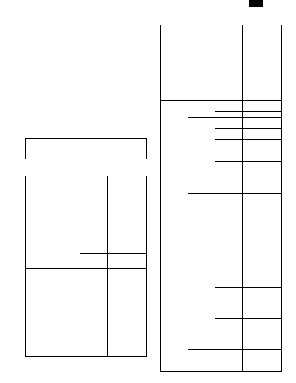
[2] Specifications
1. Basic Specification
Item
External dimensions H464 × W518 × D477 mm
Weight 24.6 kg
2. Operation specification
Section item Details
Paper feed
section
Paper for
Duplex
Electrical
section
Installed memory 6MB
∗1) May fluctuate due to environmental conditions and the input volt-
age.
Paper feed
system
AB system
Inch system
Power
source
Power
consumption
Paper size
Paper weight 56-80g/m
Kinds
Paper size
Paper weight 15-21lbs
Kinds
Voltage
Frequency
Max 1000 W
Average
(during
copying)
Average
(stand-by)
Pre-heat
mode
Auto power
shut-off
mode
2 tray (250sheet ×
2) + Multi bypass
(50sheet)
A4, B5, A5
(Landscape)
Standard paper,
specified paper,
Recycled paper
8-1/2" × 14", 8-
1/2" × 11", 8-1/2"
(Landscape)
Standard paper,
specified paper,
Recycled paper
100V 110V
120/127V 230V
Common use for
50 and 60Hz
285Wh/H ∗1)
70Wh/H ∗1)
40Wh/H ∗1)
18Wh/H ∗1)
2
× 5-1/2"
240V
3. Copy performance
Section item Details
Copy speed
Copy speed
(OC)
Copy Speed
(R-SPF) A4,
8-1/2"-11"
(Landscape)
Void
1 – 1
First copy
time
AB system:
A4
(Landscape)
B5
(Landscape)
Inch
system: 81/2" × 14"
(Landscape)
8-1/2" × 11"
(Landscape)
S to S
S to D Single copy
D to S
D to D Single copy
Void area
OC (Without
Duplex)
Image loss
OC (Without
Duplex)
Void area RSPF
(Without
Duplex)
9.6sec. (Pre-heat
mode: 16sec. or
delow/Auto power-
Tray paper
feed
Manual
paper feed
R-SPF Tray1: 13.5sec.
Same size 15
Enlargement 15
Reduction 15
Same size 15
Enlargement 15
Reduction 15
Same size 12
Enlargement 12
Reduction 12
Same size 15
Enlargement 15
Reduction 15
Single copy
Multi copy
Single copy
Multi copy
Ieading edge 1 ∼ 4mm
Trailing edge 4mm or less
Side edge
void area
Ieading edge
Trailing edge
Side edge
void area
Ieading edge 1 ∼ 4mm
Trailing edge 4mm or less
Side edge
void area
shut-off mode:
23sec. or delow
Feed from
Tray1/Scan Once
Print Many Mode:
13.sec.)
Single:
10.0sec./Multi:
8.0sec. (Pre-heat
mode: 16sec.)
Tray1: 12CPM,
Tray2: 9CPM
Tray1: 15CPM,
Tray2: 15CPM
Tray1: 5.6CPM,
Tray2: 5.4CPM
Tray1: 6.2CPM,
Tray2: 6.2CPM
Tray1: 15CPM,
Tray2: 15CPM
Tray1: 5.2CPM,
Tray2: 5.0CPM
3mm or less (per
side)
Same size: 3.0mm
or less
Enlarge (200):
1.5mm or less
Reduction (50):
6.0mm or less
Same size: 4.0mm
or less
Enlarge (200):
4.0mm or less
Reduction (50):
4.0mm or less
Same size: 2.0mm
or less
Enlarge (200):
2.0mm or less
Reduction (50):
2.0mm or less
3mm or less(per
side)
Page 3
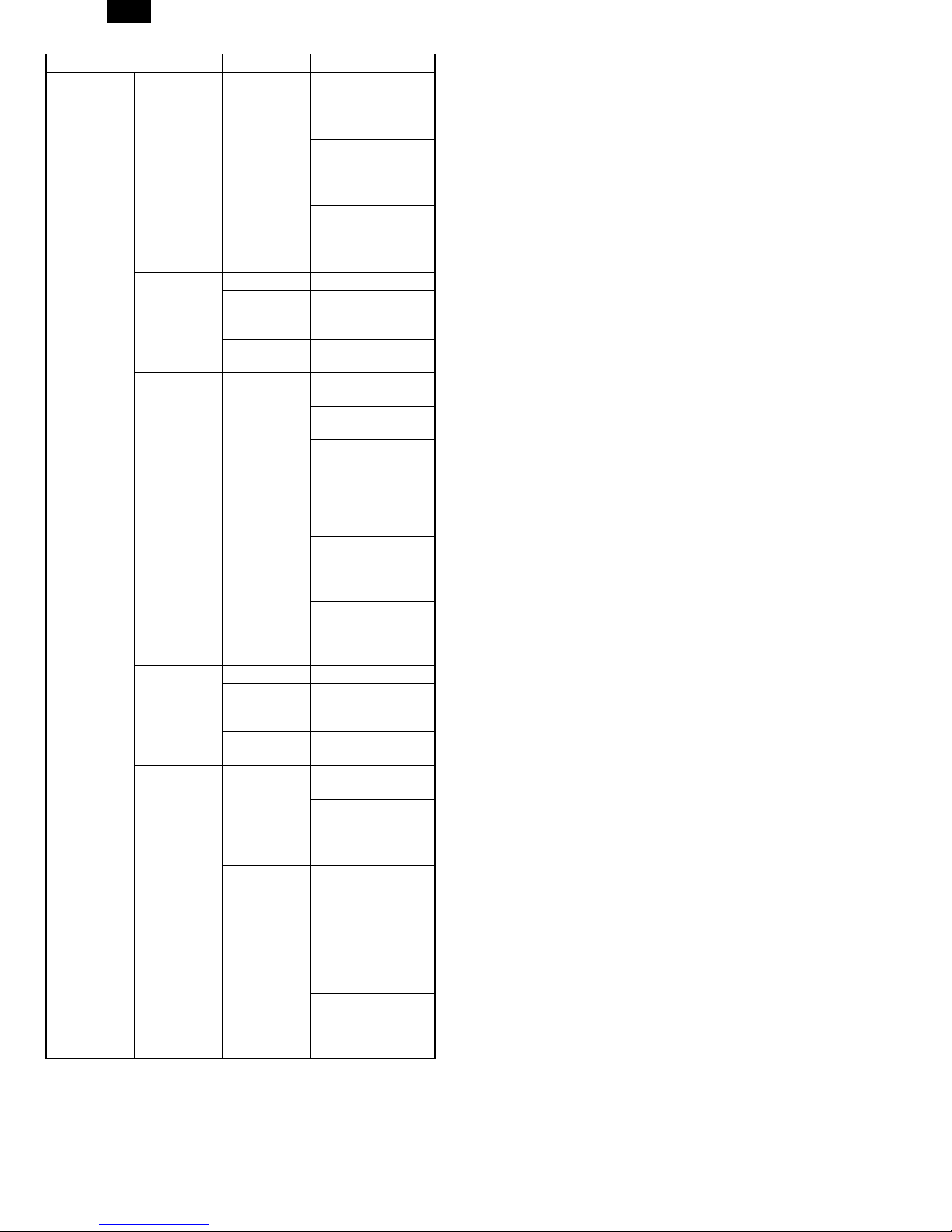
Void
AL-1550
Section item Details
Ieading edge
Image loss
R-SPF
(Without
Duplex)
Trailing edge
Ieading edge 1 ∼ 4mm
Void area
OC (Duplex)
Image loss
OC (Duplex)
Void area RSPF (Duplex)
Image loss
R-SPF
(Duplex)
Trailing edge
Side edge
void area
Ieading edge
Trailing edge
Ieading edge 1 ∼ 4mm
Trailing edge
Side edge
void area
Ieading edge
Trailing edge
Same size: 4.0mm
or less
Enlarge (200):
3.0mm or less
Reduction (50):
7.0mm or less
Same size: 4.0mm
or less
Enlarge (200):
2.0mm or less
Reduction (50):
8.0mm or less
1st Page: 5mm +/–
1.0, 2nd Page:
5mm or less
3mm or less (per
side)
Same size: 3.0mm
or less
Enlarge (200):
2.0mm or less
Reduction (50):
6.0mm or less
Same size: 1st
Page: 5.0mm +/–
1.0, 2nd Page:
5.0mm or less
Enlarge (200): 1st
Page: 2.5mm +/–
1.0, 2nd Page:
2.5mm or less
Reduction (50):
1st Page: 10.0mm
+/– 1.0, 2nd Page:
10.0mm or less
1st Page: 5mm +/–
1.0, 2nd Page:
5mm or less
3mm or less (per
side)
Same size: 4.0mm
or less
Enlarge (200):
3.0mm or less
Reduction (50):
7.0mm or less
Same size: 1st
Page: 5.0mm +/–
1.0, 2nd Page:
5.0mm or less
Enlarge (200): 1st
Page: 2.5mm +/–
1.0, 2nd Page:
2.5mm or less
Reduction (50):
1st Page: 10.0mm
+/– 1.0, 2nd Page:
10.0mm or less
1 – 2
Page 4
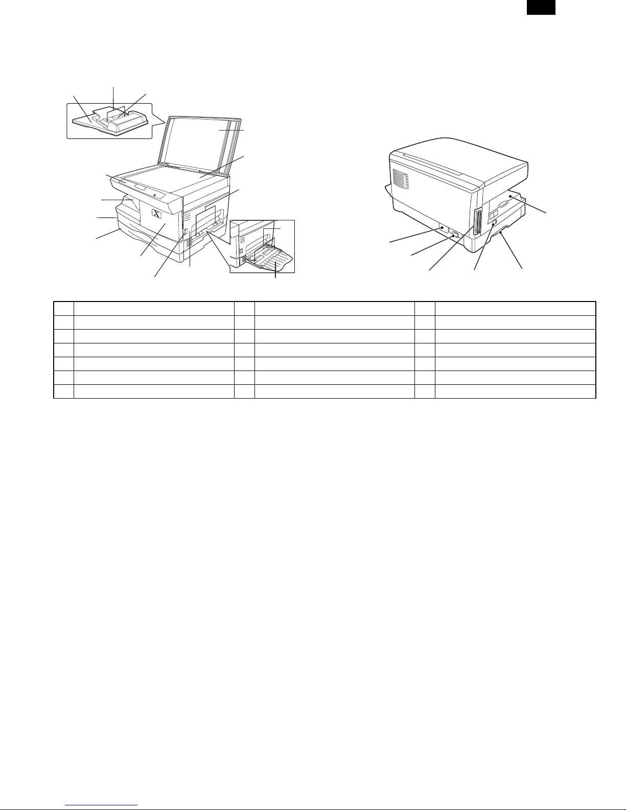
[3] EXTERNAL VIEWS AND INTERNAL STRUCTURES
1. Appearance
4
3
SPF XD103f/ 105f/ 120f
ADF XD155df only
1
15
13
14
1 Control panel 2 Document glass 3 Original exit area
4 Original guides 5 Original feeder tray 6 Document cover
7 Side cover 8 Paper tray bypass paper guides 9 Alternate paper tray
10 Paper guides 11 Release latch 12 Front cover
13 Paper tray 1 14 Paper tray 2 15 Exit tray
16 Lift area 17 Power switch 18 Power connection
19 Parallel port 20 Serial number
∗1 XD104/105f/124f/155df only
∗2 XD120f/124f/155df only
5
6
2
8
10
20
12
7
11
9
18
19
17
AL-1550
15
16
3 – 1
Page 5
AL-1550
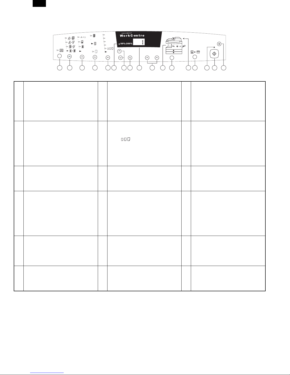
2. Control Panel
20 0% Ma x
129%
86%
78%
Auto
134567810 1416171592 1311 12
The control panel has keys and lights that are used to control and display the conditions of the WorkCentre.
Book Mode (XD104/124f only): Select
book mode when you want to make
copies from a bound document.
1
Copy Contrast: Press the contrast keys
to lighten or darken copies while in the
Text, Photo, or Toner Save settings.
Refer to the Image Quality section for
detailed information.
4
Variable Percentage: Press the down
key to decrease the percentage. Press
7
the up key to increase the percentage.
Any percentage from 50% to 200%
may be selected.
Quantity Keys: Select up to 100
copies. Press the 1 key to increase
the quantity by one. Press the 10 key
to increase the quantity by 10.
10
∗ To display the number of copies
requested during the copy run press
the 10 key.
∗ Press the Clear key to clear the
selected quantity.
SPF/ADF Misfeed Indicator: This
indicator will light when a misfeed
occurs in the SPF or the ADF.
13
Start: Press this key to begin copying.
∗ The display will change to 1 and
16
increases by 1 as each copy is
made.
10 0 %
1
10
1-Sided/2-Sided Mode (XD155df only):
Use the 2-Sided copy feature to make
one or two-sided copies from one or
two-sided originals. Refer to the
2
Making Copies on the Automatic
Document Feeder section for detailed
information.
Preset Reduction/Enlargement: Press
this key to select any of the preset
reductions or enlargements.
∗ The (customer settable)
5
percentage has been set at the
factory for 50%. Refer to
Customizing Your WorkCentre for
information about changing this
percentage.
%: Press this key to display the
reduction/enlargement percentage
8
selected. 9
WorkCentre Diagram: Helps you locate
areas that require your attention. The
indicators will flash in the area
requiring attention. For additional
information refer to the Problem
11
Solving section.
On-line/Off-line Key: Press this button
to alternate between On-line and Offline status. When the light is lit, the
14
printer is On-line.
Clear/Stop: Press this key to stop the
WorkCentre while making copies or to
17
clear copy quantity. If the key is
pressed twice quickly, all programming
will be cleared.
Image Quality Mode: The image quality
mode is used to maximiz e copy quality.
Auto- for originals with a colored
background or mixed text and graphics.
3
Text - for originals that contain mainly text.
Photo - for copying photographs.
Toner Save - decreases the overall
copy density.
Percentage Indicator: The indicator will
light when any reduction or
enlargement setting is selected.
6
Display Window: Copy quantity,
reduction/enlargement settings, and
status codes appear in this area.
Paper Supply Selection
(XD104/105f/120f/124f/155df only):
Press to change the selected paper
supply. The selected paper supply
location will be indicated by a green
12
light on the WorkCentre diagram.
Ready Indicator: When the light is ON
(not flashing), the WorkCentre is ready
to make copies. When the light is
15
flashing after the Start key is pressed,
the WorkCentre is warming up and the
copy cycle will begin automatically.
C
3 – 2
Page 6
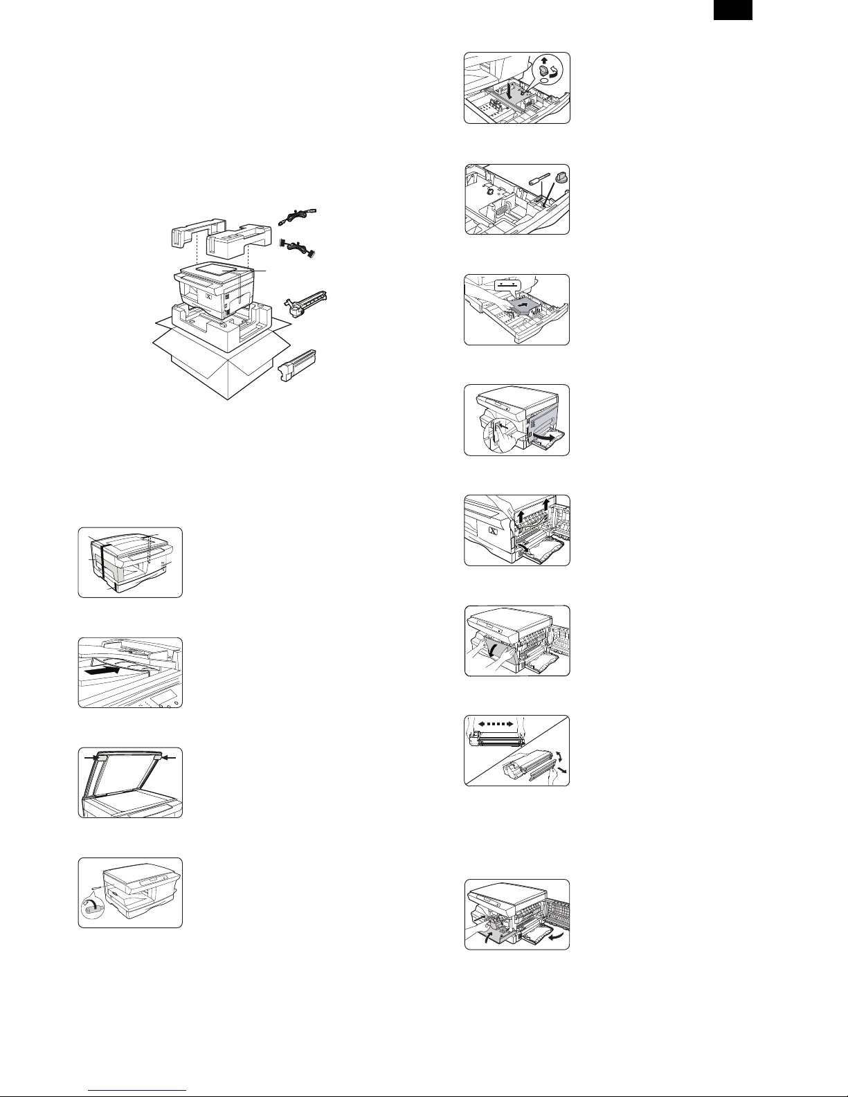
[4] UNPACKING AND INSTALLATION
1. CHECKING PACKED COMPONENTS
AND ACCESSORIES
As you unpack the WorkCentre, familiarize yourself with its contents.
After the WorkCentre is installed, and the Ready Indicator is lit, the
WorkCentre is ready to make copies.
IMPORTANT: Save the carton and packing materials. They should be
used to repack the WorkCentre if it has to be shipped
for servicing or in case you move.
Power cord
IEEE-1284
Parallel Cable *
Packing material
User documentation/
Installation CD
Drum cartridge
(installed in the
machine)
AL-1550
5) Lift and pull open the paper tray.
Turn and remove the paper tray
button.
CAUTION: Paper will misfeed if the paper
For the XD 120f/124f/155df copier only
Note: Be sure to remove the pressure
6) Secure the paper tray button and the
Note: Save the paper tray button and the
7) Load paper into the tray.
8) Push the paper tray firmly back into
tray button is not removed.
plate lock from both paper trays.
shipping screw in the locations shown.
●
Turn the paper tray button to secure
its storage position.
shipping screw. They will be
needed if the WorkCentre has to
be moved.
●
Refer to the Loading Paper section
for additional information.
●
Do not fill above the max line.
the WorkCentre.
Starter toner
cartridge
∗Note: To ensure reliability of the WorkCentre use the IEEE-1284
compliant parallel cable that is supplied with the machine. Only
cables labeled "IEEE-1284" can be used with your WorkCentre.
2. Installation
Follow the steps below to properly set up your Xerox WorkCentre.
A
E
B
1) Remove the bag from the WorkCentre.
D
2) Remove the pieces of tape A, B, C,
C
D, and the packing material E.
XD155df copier only
Remove the tape and the packing material
supporting the clear plastic 2-sided tray.
XD155df copier only
To ensure the 2-sided tray is in the
correct position, gently push it in the
direction shown by the arrow.
3) Open the document cover and
remove the packing materials shown.
4) Unscrew and remove the shipping
screw from the left side of the
WorkCentre.
CAUTION: The WorkCentre will
malfunction if the shipping
screw is not removed.
Note: Ensure that the alternate paper tray
is lowered (XD 104/124f/155df only).
9) Press the release lever to open the
side cover.
10) Remove the Caution tape from the
cover.
11) Remove the two red fuser pins by
pulling the string upward one at a
time.
●
Discard the fuser pins.
Note: Misfeeds will occur if the fuser pins
are not removed.
CAUTION: Ensure that the side cover is
always open before opening
the front cover.
12) Press the front cover release buttons
to open the front cover.
13) Remove the starter toner cartridge
from the silver bag. Vigorously shake
1
2
the cartridge to loosen the toner.
●
Thoroughly shaking the cartridge will
assure maximum copies per
cartridge.
●
Xerox has included a Starter Toner
Cartridge. Purchased replacement
toner cartridges will yield
approximately three times the number
of copies.
14) Remove the toner cartridge cover.
15) Slide the toner cartridge into the
WorkCentre until it locks into place.
16) Close the front cover and the side
1
2
3
cover.
Skip to the Printer Driver Software
Installation section in this User Guide to
set up the WorkCentre XD for printing.
4 – 1
Page 7
AL-1550
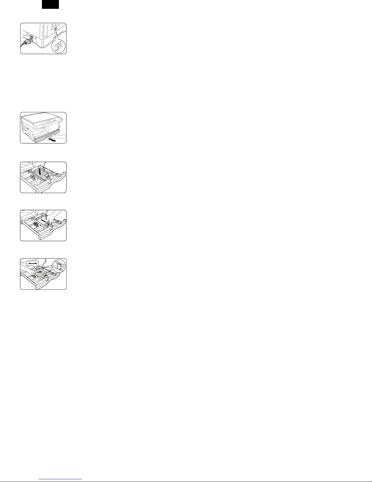
17) Plug the power cord into the
18) Turn on the power switch. In
Note: Save the carton and packing
3. P Loading Paper
1) Lift and pull open the paper tray.
2) Push down on the pressure plate
Note: The procedures for loading paper
WorkCentre and then into a grounded
outlet.
approximately two seconds the ready
indicator will light. Copying is now
possible.
materials. They should be used to
repack the WorkCentre if it has to
be shipped for servicing or moved.
until it locks in position.
into tray 1 and tray 2 are identical.
3) Adjust the paper guides to the
desired paper size.
●
Squeeze the side guide.
●
Lift and insert the rear guide.
●
When adding paper larger than
8.5L11/A4, remove the rear guide and
store it in the pocket in front of the
side guide.
4) Fan the paper and insert it into the
tray.
●
Ensure that the paper corners are
under the corner snubbers.
●
Do not fill above the max fill line.
5) Close the paper tray.
6) If copying, press Start to continue. If
printing, the job will automatically
resume.
●
To cancel the flashing P without
restarting copying, press the Clear
button.
4 – 2
Page 8
AL-1550
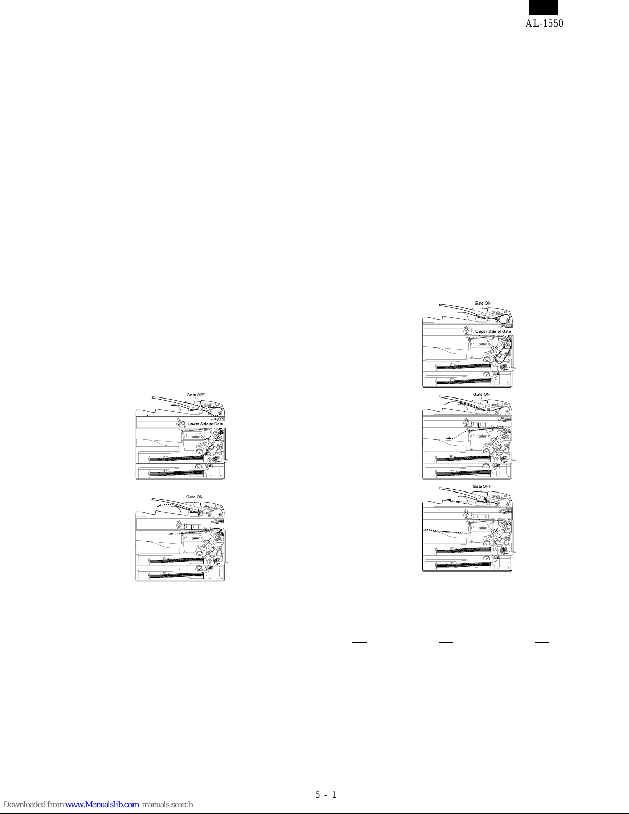
[5] Operational descriptions
1. D-D (Duplex to Duplex) mode
paper/document transport
A. Initial state
Set duplex documents on the document tray.
Set paper on the cassette. (In the duplex mode, the manual feed tray
cannot be selected.)
B. Front copy
Document transport: The document feed roller feeds the document
from the paper feed roller to the PS roller.
→ The document is exposed in the exposure
section, and sent to the document exit section
by the transport/paper exit roller.
→ R-SPF gate solenoid ON
→ The document is sent to the intermediate tray
(but not discharged completely.)
→ The document is stopped once, then
switchback operation is performed. (To the
back copy)
Paper transport: The document is passed through the paper feed
roller and the PS roller by the paper feed roller
and the images on the front surface are transferred.
→ The paper is passed through the fusing sec-
tion and the lower side of the gate section to
the paper exit tray side, (but not discharged
completely.)
→ It is stopped once and switchback operation
is performed. (To the back copy)
Gate OFF
C. Back copy
Document transport: By switchback operation, the document is sent
through the PS roller to the exposure section,
where the back of the document is exposed.
→ It is sent to the document exit section by the
transport roller and the paper exit roller.
→ R-SPF gate solenoid ON. The document is
sent to the intermediate tray, (but not discharged completely.)
→ It is stopped once and switchback operation
is performed.
→ It is sent through the PS roller and the ex-
posure section (without exposure operation)
to the document exit section.
→ R-SPF gate solenoid OFF
→ The document is discharged to the document
exit tray.
Paper transport: Switchback operation is performed.
→ The paper is sent through the upper side of
the gate section and the duplex transport section, and the PS roller, and the images on the
back are transferred.
→ It is sent through the fusing section and dis-
charged to the paper exit tray.
Gate ON
Upper Side of Gate
Gate ON
Lower Side of Gate
Gate ON
Gate OFF
Switchback operation is made after back copying in order to discharge
documents according to the setting.
Set document Documents after discharge,
1
with empty feed
23 4
4
without empty feed
3
32 1
41 2
There are following job modes as well as D-D mode.
S - S (Simplex to Simplex)
S - D (Simplex to Duplex), Rotation copy mode (The back images are
rotated 180˚.)
S - D (Simplex to Duplex), Copy mode without rotation
D - S (Duplex to Simplex)
Rotation copy mode: The front and the back are in upside
down each other.
Copy mode without rotation: The front and the back are not in upside
down.
5 – 1
Page 9

[8] SIMULATION, TROUBLE CODES
1. Contents of simulations
Main code Sub code Content
26 4 Main body duplex setting
(Operation/procedure)
1. When this simulation is executed, the currently set duplex code number is displayed.
2. ???????
Code number Duplex
0 Without Duplex
1 With Duplex
43 1 Fusing temperature setting
(Operation/Procedure)
1. When this simulation is executed, the currently set code number is displayed.
2. Enter the code number and press the START key, and the setting will be changed.
Code number Set temperature (˚C)
0 175
1 180
2 185
3 190
4 195 (∗ Default)
5 200
4 Multi copy fusing temperature setting
(Operation/Procedure)
1. When this simulation is executed, the currently set code number is displayed.
2. Enter the code number and press the START key, and the setting will be changed.
Code number Set temperature (˚C)
0 155
1 160
2 165
3 170 (∗ Default)
4 175
5 180
AL-1550
5 Fusing temperature setting in duplex copying
(Operation/Procedure)
1. When this simulation is executed, the currently set code number is displayed.
2. Enter the code number corresponding to the duplex and press the START key. The setting is changed accordingly.
Code number Shift temperature (˚C)
0 ±0˚C
1 –8˚C
2 –6˚C
3 –4˚C
4 –2˚C
5 ±0˚C
6 +2˚C
7 +4˚C
8 +6˚C
9 +8˚C
The above shift temperature set by this simulation is added to the fusing temperature of single copy.
∗
8 – 1
Page 10

AL-1550
Main code Sub code Content
51 2 Resist amount adjustment (Outline)
Used to adjust the contact pressure of paper onto the copier resist roller and the RSPF resist roller.
(Operation/Procedure)
1. When this simulation is executed, the currently set value is displayed.
2. In a machine with the multi paper feed unit installed, press the copy mode select key, and each setting mode and
display are changed sequentially.
In a machine with the single paper feed unit installed, press the copy mode select key, and each setting mode
and display are changed sequentially.
∗ The selected adjustment mode is indicated by the lamps as follows:
3. Enter the adjustment value with the 10-key and press the SORT key. Then the set value is stored and a copy is
made.
4. Press the clear key to store the set value and exit the simulation.
∗ Machine with the multi manual paper feed
Adjustment mode Display lamp
Main cassette paper feed AE, Main cassette lamp
2nd cassette paper feed AE, 2nd cassette lamp
Manual paper feed AE, Manual paper feed lamp
RSPF document feed (front) AE, TEXT, PHOTO lamp
RSPF document feed (back) AE, TEXT lamp
Duplex back TEXT, PHOTO lamp
∗ Machine with the single manual paper feed
Adjustment mode Display lamp
Main cassette paper feed AE, Main cassette lamp
Manual paper feed AE blinking (Main cassette lamp ON)
RSPF document feed (front) AE, TEXT, PHOTO lamp
RSPF document feed (back) AE, TEXT lamp
Duplex back TEXT, PHOTO lamp
77 1 Memory reverse position adjustment in duplex copy (Operation/Procedure)
1. When this simulation is executed, the currently set correction value is displayed.
2. Enter the correction value with the 10-key, press the START key, and the entered value is stored. (Correction
value: 1 - 99, Correction zero: 0 or 50)
∗ For front printing in S-D mode and even-page printing in D-S mode, reverse memory copying made from the rear
edge of the document.
If, therefore, it is required to adjust the print position of the output image, perform the following procedure.
When the document is scanned in the direction shown in the figure below, images are printed from the scanning
rear edge in reverse memory copying.
If the print head is shifted, set the reference chart so that the reference position is at the rear edge section and
use this simulation so that the lead edge of the print image is fitted.
Printing is started at the print start position in the direction from the bottom to the top of image data stored in the
memory.
When the simulation set value is entered, the scanning end position and resultantly the bottom data position stored
in the memory are changed to adjust the image lead edge position.
Document transport direction
Scanning rear edgeScanning direction
Scanning lead edge
Scanning end position
(Default: Void (1) is cut off.)
Paper transport direction
2 Duplex copy rear edge void adjustment (Operation/Procedure)
1. When this simulation is executed, the currently st value is displayed in top digits. (Center value: 50 However, Set
value 50 = Set value 0)
2. Press the copy mode select key to select the set mode and the display.
3. Enter the adjustment value with the 10-key and press the START key, and the entered value is stored and a copy
is made.
4. Press the CLEAR key, and the entered value is stored and the simulation is terminated. (An increase in the set
value by 1 corresponds to an increase in void amount by 0.1 mm.)
Adjustment mode Lamp ON
Image cut rear edge void amount (RSPF) AE lamp
Paper rear edge void amount TEXT lamp
Print lead edge
Lead edge void (1)
Print start position
Rear edge void
Print rear edge
8 – 2
Page 11

[9] USER PROGRAM
The conditions of factory setting can be changed according to the use conditions.
1. Functions which can be set with the user program
Function Contents Factory setting
●
Auto clear.
Pre-heat.
Auto shut off
passing time.
Stream feeding.
Auto shut off setting
∗Note: The power consumption values in pre-heat and auto shut off may be varied depending on the use conditions.
When a certain time is passed after completion of copying, this function returns to the initial state
automatically. The time to reach the initial state can be set in the range of 10 sec to 120 sec. This
function can be disabled.
●
When the copier is left unused with the power ON, the power consumption is automatically reduced
to about 40Wh/H (∗ Note).
The time to start this function can be set in the range of 30 sec to 90 sec by the unit of 30 sec.
This function cannot be disabled.
●
When this function is operated, the pre-heat lamp on the operation panel lights up.
To return to the initial state, press any key on the operation panel. (When the COPY button is
pressed, a copy is made after returning to the initial state.)
●
When the copier is left unused with the power ON, the power consumption is automatically reduced
to about 18Wh/H (∗ Note). The time to start this function can be set in the range of 2 min to 120
min.
●
When this function is operated, all the lamps except for the pre-heat lamp on the operation panel
turn off.
To return to the initial state, press the COPY button.
After completion of copying with the automatic document feeder (SPF), when documents are set
while the SPF indicator is blinking (for about 5 sec), the documents are automatically fed.
●
Used to set or cancel this function. Set
AL-1550
60 sec
90 sec
5 min
Set
2. Change the setting.
Example: Changing the time to operate the auto shut off function
1) Press the right and the left exposure adjustment keys simul-
● Keep pressing the keys for five sec.
● Displ ay lamps ( , , ) blink simult aneously and “ - -” is
displayed on the copy quantity display.
2) Select the function code with the 10-digit key (copy quantity
● The number of the selected function blinks on the digit of 10 on the
copy quantity display.
● For auto clear, select “1.”
● For setting, refer to the following function codes.
Function
name
Auto clear
∗ : Factory setting
(Change from 60 sec to 90 sec)
taneously to start setting.
set key).
Set code
0 (Cancel)
1 (30 sec) 1 (60 sec) ∗1 (5 min) ∗1 (Setting) ∗1 (Setting)
∗2 (60 sec) ∗2 (90 sec) 2 (15 min)
3 (90 sec) 3 (30 min)
4 (120 sec) 4 (60 min)
5 (10 sec) 5 (120 min)
Function
name
Pre-heat
Set code
0 (30 sec)
Function
name
Auto shut
off
Function name Function code
Auto clear 1
Pre-heat 2
Auto shut off passing time 3
Stream feeding 4∗
Auto shut off setting 5
[Cancel] If a wrong code is entered, press the clear key and enter the
3) Press the COPY button.
● The number blinking on the digit of 10 of the coyp quantity display
● The number of the current set code blinks on the digit of 1.
4) Select the setting code with 1-digit key (copy quantity set key).
● To set to 90 sec, select “3.”
● For setting, refer to the following set codes.
Set code
0 (2 min)
correct function code.
is lighted.
Function
name
Stream
feeding
Set code
0 (Cancel)
Function
name
Auto shut
off setting
Set code
0 (Cancel)
● The number of the selected set code blinks on the digit of 1 of the
copy quantity display.
[Cancel] When a wrong number of the function code is set, press the
clear key and perform the procedure again from 2.
5) Press the COPY button.
● The number blinking on the digit of 1 of the copy quantity display is
lighted up. This means the setting is completed.
[Note] To set another function, press the clear key after completion of
this operation and perform the procedure from 2.
6) Press either one of exposure adjustment keys
( or ) to complete the setting.
● Display lamps ( , , ) go off and the copy quantity dis-
play returns to the normal state.
9 – 1
Page 12

[10] ELECTRICAL SECTION
1. Block diagram
A. Overall block diagram
AL-1550
10 – 1
Page 13

AL-1550
B. Main PWB block diagram
10 – 2
Page 14

2. Circuit descriptions
A. Main PWB (MCU)
(1) CPU signal table
The additional signal is as follows:
Pin No. Signal name In/Out During operation
31 SPPD Input SPF paper transport detection signal
109 SIN3 Input Sensor input 3
115 DMT3 Motor Output Duplex motor control signal
116 DMT2 Motor Output Duplex motor control signal
117 DMT1 Motor Output Duplex motor control signal
118 DMT0 Motor Output Duplex motor control signal
The signals of function change are as follows:
Pin No. Signal name In/Out During operation
119 MRMT3 Motor output Mirror motor/SPF motor control signal
120 MRMT2 Motor output Mirror motor/SPF motor control signal
121 MRMT1 Motor output Mirror motor/SPF motor control signal
122 MRMT0 Motor output Mirror motor/SPF motor control signal
(2) ASIC signal table
The additional signal is as follows:
Pin No. Signal name In/Out Connection Descriptions
SPF gate solenoid control
201 SGS Output TR array IC
202 SRRC Output TR array IC
203 SPUS Output TR array IC
208 SPFS Output TR array IC
209 SMSEL Output TR array IC
227 CPFS2 Output TR array IC
signal. “H”: Gate solenoid
ON (R-SPF only)
SPF resist roller clutch
control signal. “H”: Clutch
ON (R-SPF only)
SPF pickup solenoid control
signal. “H”: Solenoid ON
SPF paper feed solenoid
control signal. “H”: Solenoid
ON (R-SPF only)
SPF/mirror motor relay
switch signal. “L”: Mirror
motor, “H”: SPF motor
2nd cassette paper feed
solenoid control signal. “H”:
Solenoid ON
AL-1550
(3) Input signal table
The additional signals are as follows:
Signal name Descriptions
SPID SPF paper entry detection signal
SPF
2nd
SDOD SPF open/close detection signal
SDSW SPF cover open/close detection signal
CED2 2nd cassette section cassette presence detection
PPD3 2nd cassette section paper transport detection
10 – 3
Page 15

AL-1550
(4) Mirror motor circuit
The mirror motor is a stepping motor. Its driver is IC113 constant-current chopper control IC (SLA7024). For control, the CPU outputs a drive
signal to IC113 to drive the mirror motor by 1-2 phase excitement.
The SPF motor and the mirror motor are switched with relays RY1 and RY2. The switching signal is SMSEL-. When SMSEL- is LOW, a current
flows through the SPF motor. When it is HIGH, a current flows through the mirror motor.
24V-mir
/SMSEL
ULN2003
24V
RY102 G5V-2(OMRON)
RY101 G5V-2(OMRON)
(5) Duplex motor circuit
The duplex motor is a stepping motor. Its driver is IC111 darlington-sink transistor driver IC (TD62064AP). For control, the CPU outputs a drive
signal to IC111 to drive the duplex motor by 1-2 phase excitement.
M
SPF motor
M
(1-C4) DMT0
(1-C4) DMT1
(1-C4) DMT2
(1-C4) DMT3
R286 2.2KJ 3
R285 2.2KJ 6
R278 2.2KJ 11
R279 2.2KJ 14
IC111
I1 O1
4
NC
5
NC
I2 O2
10
NC
I3 O3
12
NC
13
NC
I4 O4
15
NC
GND COM
GND COM
TD62064AF
CP101
24V1
ICP-N38
2
7
9
D123
MTZJ22B
16
M
1
8
Duplex Motor
10 – 4
Page 16

[11] CIRCUIT DIAGRAM
AL-1550
MCU 1
11 – 1
Page 17

AL-1550
MCU 2
11 – 2
Page 18

AL-1550
MCU 3
11 – 3
Page 19

AL-1550
MCU 4
11 – 4
Page 20

AL-1550
MCU 5
11 – 5
Page 21

AL-1550
MCU 6
11 – 6
Page 22

AL-1550
MCU 7
11 – 7
Page 23

AL-1550
OPU
11 – 8
Page 24

AL-1550
ACTUAL WIRING DIAGRAM 1
11 – 9
Page 25

AL-1550
ACTUAL WIRING DIAGRAM 2 (DSPF UNIT)
11 – 10
Page 26

AL-1550
COPYRIGHT © 1999 BY SHARP CORPORATION
All rights reserved.
Printed in Japan.
No part of this publication may be reproduced,
stored in a retrieval system, or transmitted,
in any form or by any means,
electronic, mechanical, photocopying, recording, or otherwise,
without prior written permission of the publisher.
SHARP CORPORATION
Printing & Reprographic Systems Group
Quality & Reliability Control Center
Yamatokoriyama, Nara 639-1186, Japan
1999 March Printed in Japan N
 Loading...