

Page 1

AR-SP5
AR-D16
SERVICE MANUAL
CODE : 00ZARSP5//A1E
DIGITAL COPIER OPTIONS
AR-PG2 AL-12PKM
[ 1 ] GENERAL . . . . . . . . . . . . . . . . . . . . . . . . . . . . . . . . . . . . . . . . . . . 1 - 1
[ 2 ] UNPACKING AND INSTALLATION . . . . . . . . . . . . . . . . . . . . . . . 2 - 1
[ 3 ] AR-SP5 . . . . . . . . . . . . . . . . . . . . . . . . . . . . . . . . . . . . . . . . . . . . . 3 - 1
[ 4 ] AR-D16 . . . . . . . . . . . . . . . . . . . . . . . . . . . . . . . . . . . . . . . . . . . . . 4 - 1
MODEL
CONTENTS
AR-SP5
AR-D16
AR-PG2
(SPF)
(1 TRAY UNIT)
(GDI/Scanner Kit)
AL-12PKM
(GDI/Scanner Kit)
[ 5 ] AR-PG2 . . . . . . . . . . . . . . . . . . . . . . . . . . . . . . . . . . . . . . . . . . . . . 5 - 1
● PARTS GUIDE
Parts marked with “ ” are important for maintaining the safety of the set. Be sure to replace these parts with
specified ones for maintaining the safety and performance of the set.
This document has been published to be used
SHARP CORPORATION
for after sales service only.
The contents are subject to change without notice.
Page 2

[1] GENERAL
1. List of available options
Model
AR-122E AR-152E AR-153E AR-157E
Option
AR-SP5
(SPF)
AR-D16
(1 TRAY UNIT)
AR-PG2
(GDI/Scanner Kit)
AL-12PKM
(GDI/Scanner Kit)
: Option available
: Option not available
B. AR-D16 (250 - Sheet Paper Feed Unit)
The paper feed unit provides the convenience of increased paper
capacity for the copier and a greater choice of paper sizes readily
available for copying.
Part names
Side cover
Tray
2. Outline and specifications of each option
A. AR-SP5 (Single Pass Feeder)
The single pass feeder (SPF) holds up to 30 originals for automatic
feeding.
Part names
Original guides
Document feeder tray
Specifications
Acceptable
originals
Power supply Drawn from the copier
Weight Approx. 6.6 lbs. (3kg)
Dimensions 19.6" (W)
Weight: 14 to 23.9 lbs.
Size: 5-1/2"
Capacity: Up to 30 sheets
(498 mm (W)
× 8-1/2" to 8-1/2" × 14"
× 15" (D) × 4.3" (H)
× 380 mm (D) × 110 mm (H))
Feeding roller cover
SPF exit area
Specifications
Copy paper size 5-1/2" × 8-1/2" to 8-1/2" × 14"
Paper weight 15 lbs. to 21 lbs.
Paper capacity One paper tray with capacity for 250 sheets of
Weight Approx. 6.6 lbs. (3 kg)
Dimensions 19.6" (W)
Power supply Drawn from the copier
21 lb. bond paper
× 15.6" (D) × 3.5" (H)
(498 mm (W)
× 395 mm (D) × 88 mm (H))
C. AR-PG2, AL-12PKM (GDI/Scanner Expansion Kit)
Printing system Dry, electrostatic transfer
Printing size A6 to A4 (3-1/2"
Print speed Max. 12 pages/min. (Letter or A4)
Continuous printing Max. 99 pages subtractive counter
First-print time
(Approximately)
Resolution Printer 600 dpi
Scanner 600
Emulation SHARP GDI
Page orientation Portrait or landscape
Interface port USB interface (USB1.1 Standard)/
*1: Feed paper lengthwise only.
*2: Data transmission time is not included.
9.6 seconds (Paper: A4) *2
× 1200 dpi
IEEE1284-compliant bi-directional parallel
interface (Only for printer)
× 5-1/2" to 8-1/2" × 14") *1
AR-SP5 GENERAL 1 - 1
Page 3
[2] UNPACKING AND INSTALLATION
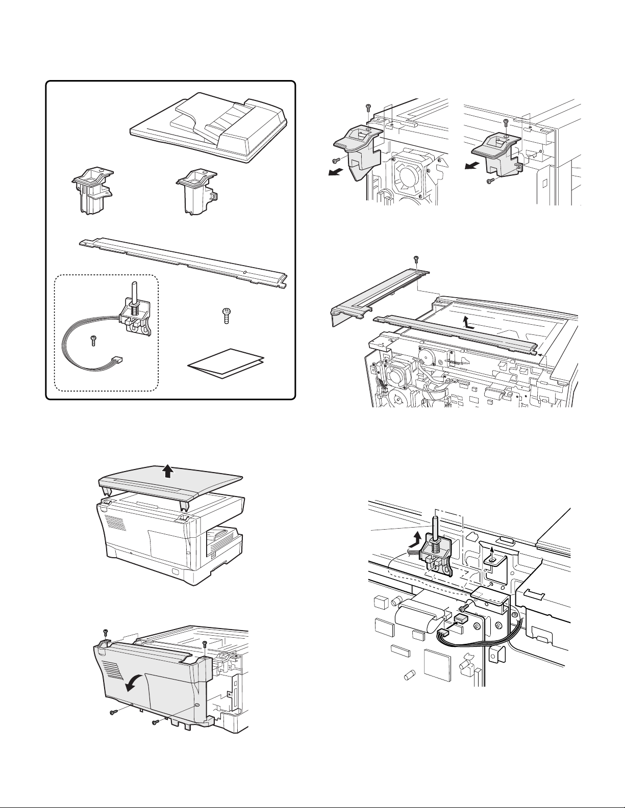
1. AR-SP5 Installation Manual
•
Parts included
• SPF unit
• Hinge guide L • Hinge guide R
• SPF rear cover, 1 pc.
• Screws (M3 × 8), 1 pcs.
3) Remove the hinge guides L and R.
Remove the screws (two for each) and then remove the hinge
guides L and R.
4) Remove the rear cover for the document glass.
<1> Remove the screw and then remove the right glass holder.
<2> Slide the rear cover for the document glass to remove it.
1
2
• Book sensor unit, 1 pc.
Turn the main switch to the “OFF” position and remove the power plug
from the outlet.
1) Remove the document cover.
Remove the document cover from the copier.
2) Remove the rear cabinet.
Remove the four screws and then remove the rear cabinet.
• Installation manual, 1 sheets
5) Attach the book sensor unit.
Insert the actuator of the book sensor unit into the mounting por-
tion in the copier and fix it using the supplied screw (M3
Note: When attaching the sensor unit, fix it using the screw while
pushing the unit upward.
Connect the connector to the connector of the copier and arrange
the wiring as shown in the illustration.
1
Actuator
2
3
× 8).
AR-SP5 UNPACKING AND INSTALLATION 2 - 1
Page 4

6) Attach the SPF rear cover.
<1> Pass the actuator of the book sensor into the hole of the SPF
rear cover and slide the SPF rear cover to attach it. At this
time, check that the pawl on the back side of the SPF rear
cover is inserted into the copier frame.
<2> Reattach the right glass holder to its original position and fix it
using the screw.
Note: Check that the actuator moves smoothly.
Take care to prevent entry of dirt into the scanner unit.
2
1
7) Attach the hinge guides L and R.
Attach the hinge guides L and R by fitting the pawls (two for each)
into the frame of the copier and secure them with the two screws
for each that have been removed in step 3.
9) Connect the SPF with the copier using the relay harness.
<1> Fit the snap band to the position shown in the illustration.
<2> Connect the connector.
<3> Fit the grounding terminal using the supplied screw (M3
1
3
10) Attach the rear cabinet.
Remove the rib from the rear cabinet.
Note: While pushing down the actuator of the sensor unit, attach
the rear cabinet so that the actuator is inserted into the hole
of the rear cabinet.
<1> Hang the four pawls shown in the illustration below on the
plate.
<2> Push down the actuator of the sensor unit.
<3> Position the cabinet to the upper screw positions.
<4> Ensure that the actuator is inserted into the square hole of
the cabinet.
2
× 8).
Pawls
8) Place the SPF on the copier.
Pawls
Side view
Pawl
M3×8
Pawl
M3×8
M4×12
AR-SP5 UNPACKING AND INSTALLATION 2 - 2
Page 5
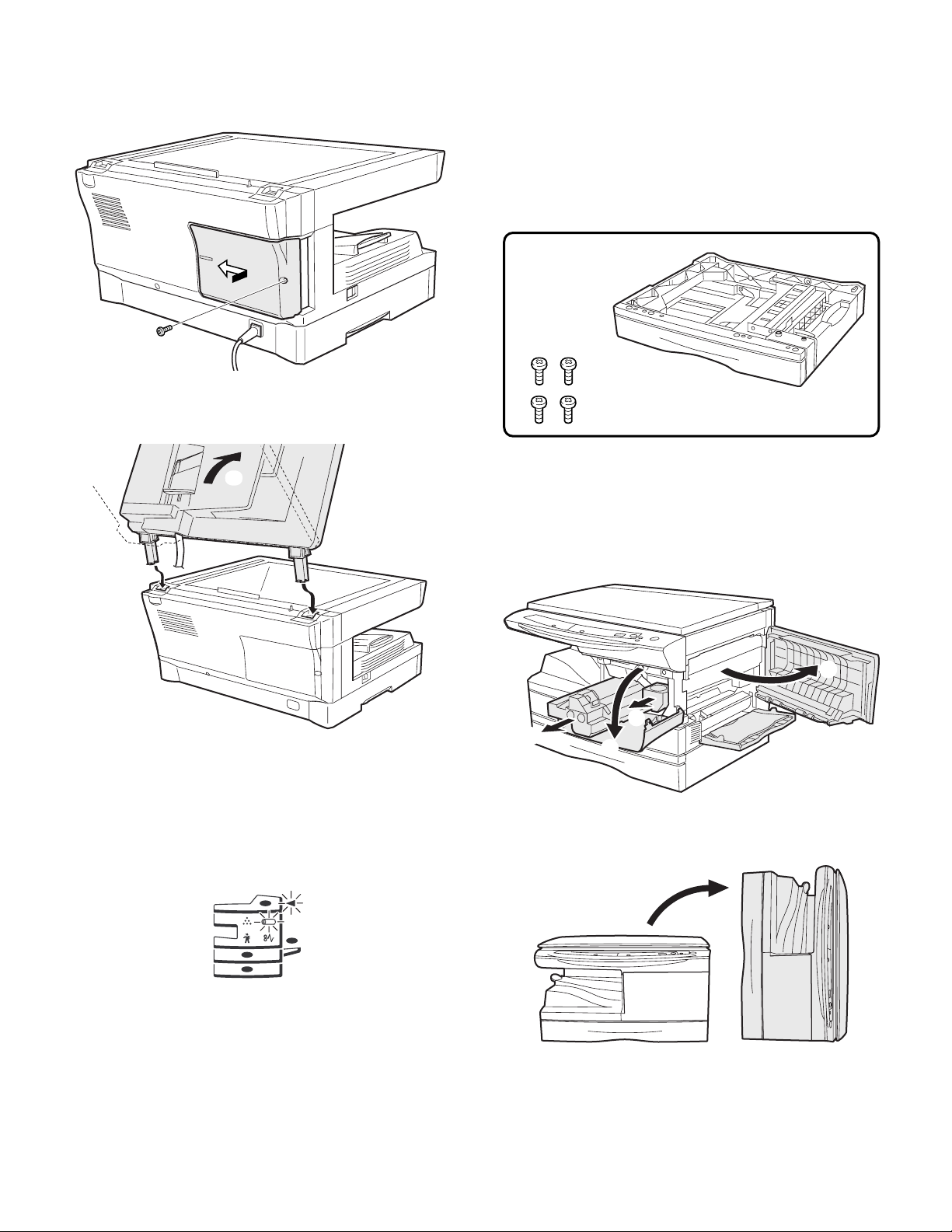
11) Attach the cover to the rear cabinet.
<1> Align the arrow marks as shown in the illustration.
<2> Then slide the cover to the left.
<3> Secure the cover with a screw.
17) Check the copy ratio, and then check the center displacement and
leading edge image void.
Place an original on the document glass and make a copy.
Then, place an original in the document feeder tray and make a
copy.
If the center of the copy from the document glass is displaced from
the copy from the document feeder, adjust the center referring to
the service manual.
2. AR-D16 Installation Manual
•
Parts included
12) Attach the SPF to the copier.
Attach the SPF by inserting the hinge guide sections of the SP5
into the hinge guides L and R.
1
2
2
13) Insert the power plug into the outlet and turn the main switch of the
copier to the “ON” position.
14) Perform SIM setting.
Execute simulation [2] of [26] and enter [1].
15) Check the ON/OFF operation of the open detection sensor.
Execute simulation [2] of [2] and check that the indicator on the
operation panel lights up and goes out by opening and closing the
SPF.
• Screws (M4 × 16), 4 pcs.
Turn the main switch to the “OFF” position and remove the power plug
from the outlet.
1) Remove the DV cartridge and the drum cartridge from the copier.
Open the tray, the side door, and the front cabinet, and then
remove the DV cartridge and the drum cartridge.
Note: Be sure to carry out the operation in the order of (1), (2), (3),
and (4).
1
4
3
2
2) Make the copier upright.
Close the front cover, side cover, and bypass tray, and then make
the copier upright in the orientation shown in the illustration.
16) Carry out automatic adjustment of SPF scanning position.
Execute simulation 53-08 to carry out automatic adjustment of
SPF scanning position.
For details, see the service manual.
AR-SP5 UNPACKING AND INSTALLATION 2 - 3
Page 6
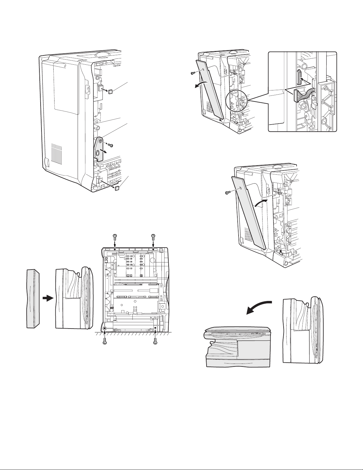
3) Remove the OP gear cover and rubber feet from the bottom of the
copier.
Remove the screw and remove the OP gear cover.
Then, take off and remove the rubber feet.
Rubber foot
OP gear cover
Rubber foot
5) Remove the rear cover and connect the connector.
Remove the screw and remove the rear cover.
Then, connect the connector of the second cassette unit to that of
the copier.
6) Attach the rear cover.
Attach the rear cover to its original position and secure it with the
screw (M4
× 12).
4) Install the second cassette unit to the copier.
If the second cassette unit is aligned to the copier, it can be posi-
tioned automatically.
Hold the copier lightly to prevent it from toppling down and secure
the second cassette unit with four screws (M4
× 16).
7) Return the copier to the normal orientation.
When returning the copier to the normal orientation, gently return it
without giving a shock.
AR-SP5 UNPACKING AND INSTALLATION 2 - 4
Page 7

8) Insert the drum cartridge and the DV cartridge into the copier.
Open the tray, the side door, and the front cabinet, insert the drum
cartridge and the DV cartridge, and then close the front cabinet,
the side door, and the tray.
Note: Be sure to carry out the operation in the order of (1), (2), (3),
and (4).
11) Load paper into the paper tray.
When loading paper, do not exceed the maximum height line.
3
1
2
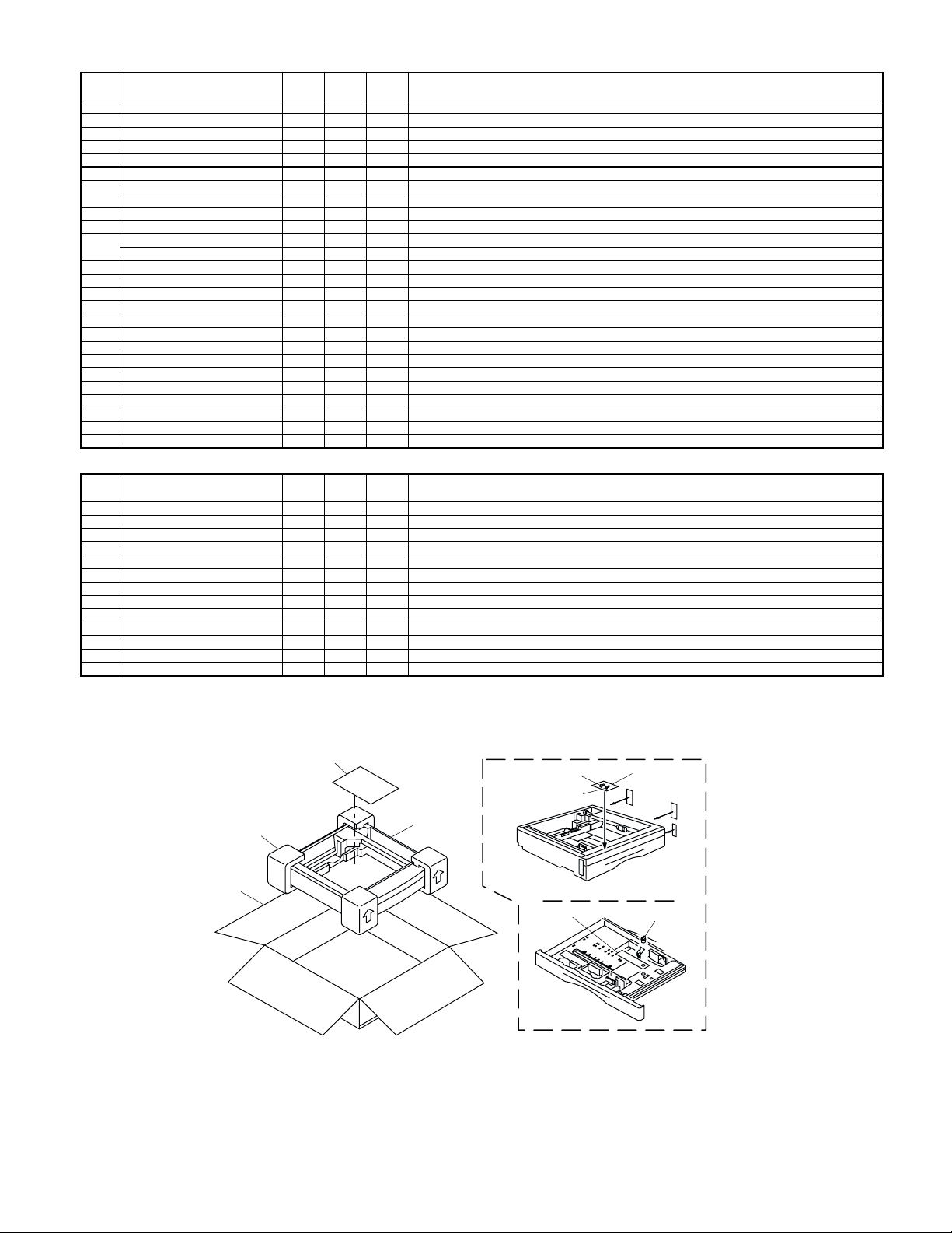
9) Remove the paper tray lock for packing.
Remove the paper tray lock for packing that secures the turning
plate in the paper tray by rotating it in the direction of the arrow and
store it in the specified position.
10) Set the paper tray side guide.
Squeeze the lever of the paper tray side guide to slide the guide to
the position for the paper size to be used.
4
12) Insert the power plug into the outlet and turn the main switch to the
“ON” position. Then, perform the following procedure.
13) Perform SIM setting.
Execute simulation [3] of [26] and enter [1].
14) Check the center displacement.
Place an original on the document glass and make a copy using
the tray in the copier.
Then, make a copy using the tray in the installed optional paper
feed unit.
If the center of the copy from the optional paper feed unit is dis-
placed from the copy from the tray in the copier, adjust the center
referring to the service manual.
3. AR-PG2/AL-12PKM
A. Installation Manual
• Parts included
• Printer board ... 1
(AR-PG2)
• Screws ... 5
• Software CD-ROM ... 1
AR-SP5 UNPACKING AND INSTALLATION 2 - 5
• Printer board ... 1
(AL-12PKM)
• Core ... 1
• Cable ... 1
(AL-12PKM only)
• Screwdriver ... 1
(AL-12PKM only)
• Installation manual ... 1
Page 8

Turn the main switch to the “OFF” position and remove the power plug
from the outlet.
1) Removing the cabinet cover.
<1> Ensure that the power switch on the unit is in the off position.
Remove the power cord from the power cord socket at the
rear of the unit.
<2> Remove the screw from the cabinet cover at the rear side of
the unit using the supplied screwdriver.
<3> Slide the cabinet cover in the direction indicated by the arrow
and pull the cover while raising it a little to remove it.
<4> Secure the printer board using the supplied five screws.
<5> Insert the cable into the printer board connector, with the side
with the blue parts facing right.
(AL-12PKM)
Printer board
connector
Blue parts
<6> Insert the core through to the middle position of the cable.
(AL-12PKM)
2) Installing the printer board.
<1> Remove the printer board from the protective bag.
<2> Insert the core as shown in the illustration.
<3> Install the printer board so that the parallel interface connec-
tor of the board is fitted into the hole for the connector.
(AR-PG2)
Hole for the
connector
Core
(AL-12PKM)
Hole for the
connector
<7> Connect the board cable to the connector of the unit.
3) Replace the cabinet cover.
<1> Bend the end of the cabinet cover at the slit and break it off.
Caution: Take care in handling the cabinet cover because the
exposed edge could be sharp and may injure your
hands.
<2> Secure the cabinet cover using the screw which has been
removed.
AR-SP5 UNPACKING AND INSTALLATION 2 - 6
Page 9

B. Installing the software
The following term is used in this section.
MFP
Means the unit as a printer and scanner.
• For this description, it is assumed that the mouse is configured for
right hand operation.
• To print or scan, the MFP must be in the online state.
• The scanner feature only works when using a USB interface cable.
• If any error message appears, solve the problem following the
instructions on the screen. After your problem is solved, the installing
procedure will be continued. Depending on your problem, you may
have to exit the installer. In this case, click the "Cancel" button to exit
the installer. After solving your problem, reinstall the software from
the beginning.
(1) Windows XP (USB/parallel interface)
Before starting the installation, make sure the USB or parallel interface
cable is not connected to the MFP.
1) Insert the supplied CD-ROM into your CD-ROM drive.
2) Click the "start" button, click "My Computer", and then double-click
the CD-ROM icon.
• When any of "Found New Hardware Wizard" messages appear
during the software installation, be sure to click the "Cancel" button.
3) Double-click the "Setup" icon.
If the language selection screen appears after you double click the
"Setup" icon, select the language you wish to use and click the
"Next" button. (Normally, the correct language is selected automatically.)
4) Select the software packages to be installed, and then click the
"Next" button.
The software packages with checkmark on the list on the screen
will be installed.
Click the "Display README" button to show the information on the
selected package.
5) Review the software packages to be installed on the screen, and
then click the "Start" button.
The software packages to be installed will be displayed on the
screen. If inappropriate packages are displayed, click the "Back"
button to select appropriate packages again.
6) Copying files for MFP driver installation and parallel interface setup
(This step will start if it was selected in step 4).
1. After confirming the message in the "Welcome" window, click
the "Next" button.
2. A dialog box appears asking you to verify that the USB or par-
allel interface cable is not connected to the MFP. Make sure
that the interface cable is not connected and click the "Next"
button.
3. Click the "Next" button in the dialog box to install the MFP
driver or Cancel to quit the installation.
The setup program will start to copy the files.
If the following screen appears while the files are being copied
(the message may appear more than once), click "Continue
Anyway".
• If you are using the parallel interface connection, do not select
the Button Manager checkbox because this feature is not supported with the parallel interface.
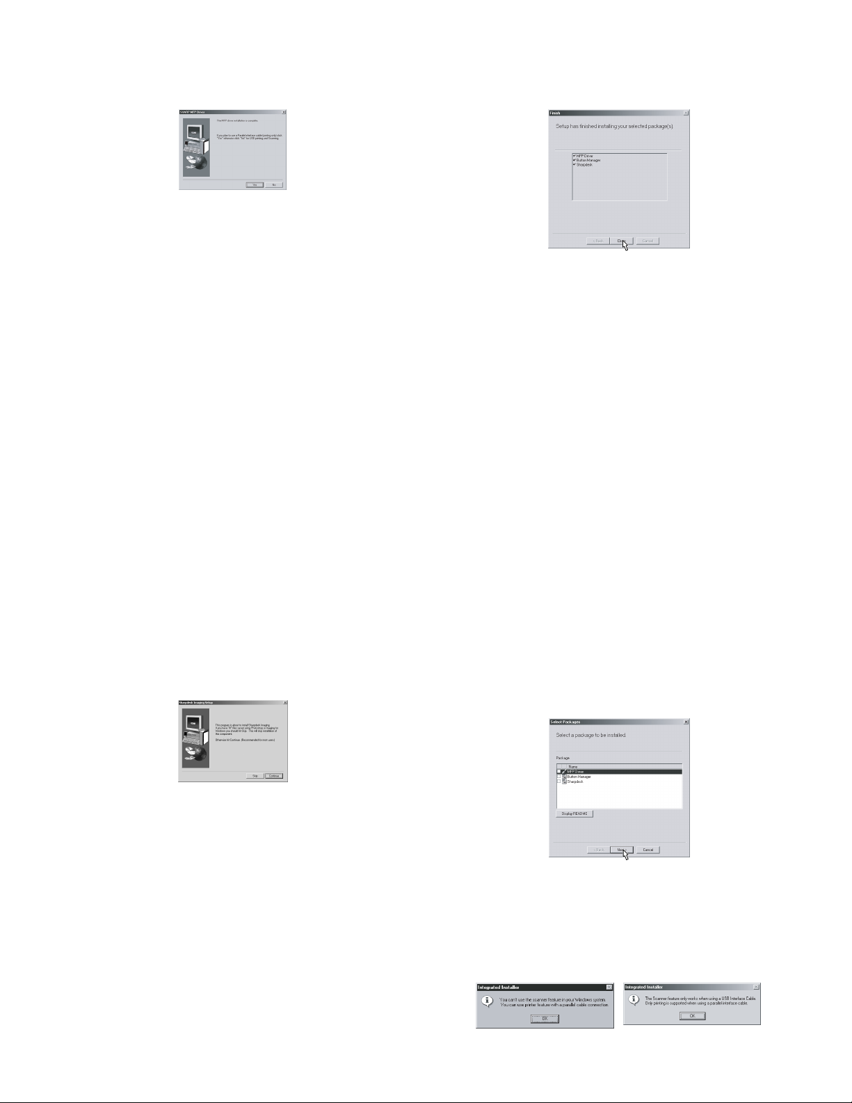
• If the following screen appears, click the "OK" button. Review
the contents in "BEFORE INSTALLATION", and then select only
appropriate the software packages to be installed.
4. When the "The MFP driver installation is complete." dialog box
appears, click the "OK" button.
The Button Manager installer will start.
7) Begin installation of the Button Manager (This step will start if it
was selected in step 4).
1. After confirming the message in the "Welcome" window, click
the "Next" button.
2. Read the message in the "Please read the following informa-
tion." window, and then click the "Next" button.
3. When a message appears that lets you specify the location for
the software to be installed, click the "Next" button.
4. If the program displays, "Do you want the Button Manager
added to Windows Startup?", check "Yes" and click the "OK"
button.
The setup program will start to copy the files.
5. Click the "Finish" button when the message informs you that
setup is successful.
The Sharpdesk installer will start.
8) Begin installation of the Sharpdesk (This step will start if it was
selected in step 4).
1. After confirming the message in the "Welcome to Sharpdesk
installation" window, click the "Next" button.
2. Read the message in the "Information" window, and then click
the "Next" button.
3. When the "Choose Destination Location" window appears,
click the "Next" button.
AR-SP5 UNPACKING AND INSTALLATION 2 - 7
Page 10

4. When the "Select Program Folder" window appears, click the
"Next" button.
The setup program will start to copy the files.
If the dialog box asking "If you have TIFF files saved using
Photo-Shop or Imaging for Windows you should hit Skip"
appears. Answer the question to continue the Sharpdesk
installation.
5. Click the "Finish" button when the message informs you that
Setup is complete.
9) Click the "Close" button when the message informs you that
"Setup has finished". When the "Now connect the MFP interface
cable to the PC" dialog box appears, click the "OK" button.
• After the installation, a message to restart your computer may be
displayed. In this case, click the "Yes" button to restart your computer.
• For parallel interface connection ensure that your computer and
MFP are turned off before connecting the cable.
(2) Windows 98/Me/2000 (USB interface)
Before starting the installation, make sure the USB interface cable is
not connected to the MFP.
1) Insert the supplied CD-ROM into your CD-ROM drive.
2) Double-click "My Computer", and then double-click the CD-ROM
icon.
• When any of "Hardware Found", or "Found New Hardware Wiz-
ard" messages appear during the software installation, be sure
to click the "Cancel" button.
3) Double-click the "Setup" icon.
• If the language selection screen appears after you double click
the "Setup" icon, select the language you wish to use and click
the "Next" button. (Normally, the correct language is selected
automatically.)
4) Select the software packages to be installed, and then click the
"Next" button.
The software packages with checkmark on the list on the screen
will be installed. Click the "Display README" button to show the
information on the selected package.
10) Connect the USB interface cable or parallel interface cable (see
page 5-8).
Windows will detect the MFP and the Plug and Play screen will
appear. If you are using Windows XP with the parallel interface, go
to step 12.
11) Begin installation of the scanner driver.
1. "SHARP AL-xxxx" (where xxxx is the model name of your
MFP) will appear in the "Found New Hardware Wizard" dialog
box. Select "Install the software automatically (Recommended)" and click the "Next" button.
2. The "Install hardware" dialog box will appear. Click the "Con-
tinue Anyway" button.
3. When installation of the driver is completed, click the "Finish"
button to finish the scanner driver installation.
12) Begin installation of the printer driver.
1. "SHARP AL-xxxx" (where xxxx is the model name of your
MFP) will appear in the "Found New Hardware Wizard" dialog
box. Select "Install the software automatically (Recommended)" and click the "Next" button.
2. The "Hardware Installation" dialog box will appear. Click the
"Continue Anyway" button.
3. When installation of the driver is completed, click the "Finish"
button to finish the printer driver installation.
You have completed the installation of all the software.
• If the following screen appears, click the "OK" button. Review
the contents in "BEFORE INSTALLATION", and then select the
appropriate driver software packages to be installed.
5) Review the software packages to be installed on the screen, and
then click the "Start" button.
The software packages to be installed will be displayed on the
screen. If inappropriate packages are displayed, click the "Back"
button to select appropriate packages again.
6) Copying files for MFP driver installation.
1. After confirming the message in the "Welcome" window, click
the "Next" button.
2. A dialog box appears asking you to verify that the interface
cable is not connected to the MFP. Make sure that the interface cable is not connected and click the "Next" button.
3. Click the "Next" button in the dialog box showing the files to be
copied for installation of the MFP driver.
The setup program will start to copy the files.
In Windows 2000, if the following screen appears while the
files are being copied (the message may appear more than
once), click "Yes" in Windows 2000.
AR-SP5 UNPACKING AND INSTALLATION 2 - 8
Page 11
4. The following screen appears when all of the files for the USB
interface connection have been copied. If you are not using a
parallel interface cable for connection to the MFP, please click
the "No" button.
5. When the "The MFP driver installation is complete." dialog box
appears, click the "OK" button.
The Button Manager installer will start.
7) Begin installation of the Button Manager (This step will start if it
was selected in step 4).
1. After confirming the message in the "Welcome" window, click
the "Next" button.
2. Read the message in the "Please read the following informa-
tion." window, and then click the "Next" button.
3. When a message appears that lets you specify the location for
the software to be installed, click the "Next" button.
4. If the program displays, "Do you want to add Button Manager
to Startup program?", check "Yes" and click the "OK" button.
The setup program will start to copy the files.
5. Click the "Finish" button when the message to inform you of
the completion of the installation appears.
The Sharpdesk installer will start.
8) Begin installation of the Sharpdesk (This step will start if it was
selected in step 4).
1. After confirming the message in the "Welcome to Sharpdesk
installation" window, click the "Next" button.
2. Read the message in the "Information" window, and then
click the "Next" button.
3. When the "Choose Destination Location" window appears,
click the "Next" button.
4. When the "Select Program Folder" window appears, click the
"Next" button.
The setup program will start to copy the files.
If the dialog box asking "If you have TIFF files saved using
Photo-Shop or Imaging for Windows you should hit Skip"
appears. Answer the question to continue the Sharpdesk
installation.
9) Click the "Close" button when the message to inform you of the
completion of the installation appears. When the "Now connect the
MFP interface cable to the PC. This will finalize the drivers installation and settings." dialog box appears, click the "OK" button.
• After the installation, a message to restart your computer may be
displayed. In this case, click the "Yes" button to restart your computer.
10) Connect the USB interface cable (see page 5-8).
Windows will detect the MFP and the Plug and Play screen will
appear.
11) Follow the instructions in the Plug and Play screen that appears in
your version of Windows to begin the installation.
You have completed the installation of the software.
(3) Windows 95/98/Me/NT4.0/2000 (Parallel interface)
Before starting the installation, make sure the USB or parallel interface
cable is not connected to the MFP.
1) Insert the supplied CD-ROM into your CD-ROM drive.
2) Double-click "My Computer", and then double-click the CD-ROM
icon.
• When any of "Hardware Found", or "Found New Hardware Wiz-
ard" messages appear during the software installation, be sure
to click the "Cancel" button.
3) Double-click the "Setup" icon.
• If the language selection screen appears after you double click
the "Setup" icon, select the language you wish to use and click
the "Next" button. (Normally, the correct language is selected
automatically.)
4) Select the software packages to be installed, and then click the
"Next" button.
The software packages with checkmark on the list on the screen
will be installed.
Click the "Display README" button to show the information on the
selected package.
5. Click the "Finish" button when the message to inform you of
the completion of the installation appears.
AR-SP5 UNPACKING AND INSTALLATION 2 - 9
• In Windows 95/NT 4.0, "Button Manager" does not appear. In
Windows 98/Me/2000, do not select the "Button Manager"
checkbox. because this is not supported when using the parallel
interface.
5) The next screen appears. Make sure that the parallel interface
cable is not connected, and click "OK".
Windows 95/NT 4.0 Windows 98/Me/2000
Page 12

6) Check the contents of the package on the screen, and then click
the "Start" button.
The software packages to be installed will be displayed on the
screen. If inappropriate packages are displayed, click the "Back"
button to select only appropriate software packages.
7) Copying files for MFP driver installation and parallel interface setup
(This step will start if it was selected in step 4).
1. After confirming the message in the "Welcome" window, click
the "Next" button.
2. A dialog box appears asking you to verify that the USB or par-
allel interface cable is not connected to the MFP. Make sure
that the interface cable is not connected and click the "Next"
button.
3. Click the "Next" button in the dialog box to install the MFP
driver or Cancel to quit the installation.
The setup program will start to copy the files.
In Windows 2000, if the following screen appears while the
files are being copied (the message may appear more than
once), click "Yes" in Windows 2000.
4. The following screen appears. Click the "Yes" button, and then
the Model screen will appear. Select the model number that is
the same as the model name of your MFP and click the "Next"
button.
Be sure to select the displayed model number that is the same
as the MFP's model name. If they are not the same, the driver
will not be installed correctly.
8) Begin installation of the Sharpdesk (This step will start if it was
selected in step 4).
1. After confirming the message in the "Welcome to Sharpdesk
installation" window, click the "Next" button.
2. Read the message in the "Information" window, and then click
the "Next" button.
3. When the "Choose Destination Location" window appears,
click the "Next" button.
4. When the "Select Program Folder" window appears, click the
"Next" button.
The setup program will start to copy the files.
If the dialog box asking "If you have TIFF files saved using
Photo-Shop or Imaging for Windows you should hit Skip"
appears. Answer the question to continue the Sharpdesk
installation.
5. Click the "Finish" button when the message to inform you of
the completion of the installation appears.
9) Click the "Close" button when the message to inform you of the
completion of the installation appears.
5. Establish the printer settings and click the "Next" button.
Select "LPT1" for the port to be used. If "LPT1" does not
appear, it is likely that another printer or peripheral device is
using "LPT1". Check your other printers and peripheral
devices, and change the port setting as needed so no device is
using "LPT1". If you wish the MFP to be your default printer,
select "Yes". If not, select "No".
6. When the "Setup has completed gathering all necessary installation information" dialog box appears, click the "Yes" button.
The parallel interface driver is installed.
7. When the "The MFP driver installation is complete." dialog box
appears, click the "OK" button.
The Sharpdesk installer will start.
• After the installation, a message to restart your computer may be
displayed. In this case, click the "Yes" button to restart your computer.
10) Connect the parallel interface cable.
You have completed the installation of all the software.
• For parallel interface connection ensure that your computer and
MFP are turned off before connecting the cable (see page 5-8).
AR-SP5 UNPACKING AND INSTALLATION 2 - 10
Page 13

[3] AR-SP5
1. Operational descriptions
A. Outline
The SPF (Single Path Feeder) is installed to the AR-153E as a standard provision, and it automatically copies up to 30 sheets of documents of a same
size. (Only one set of copies)
B. Document transport path and basic composition
(1) Pickup roller (2) Sheet of document for paper feed (3) Set detection ACT
(4) Paper stopper (5) Document feed roller (6) Separation sheet
(7) Paper entry sensor (8) PS roller D (9) Transport follower roller
(10) Paper exit roller (11) Paper exit follower roller (12) Document tray
C. Operational descriptions
Time chart (Tray feed)
Document set
(Copier side)
MM rotation
CPFS ON
PPD ON
RRC ON
(Transfer)
(Fusing)
POD ON
SPID ON
Document feed unit lamp ON
PSW ON
MIRM rotation
Main motor rotation
Paper feed
Synchronization
Paper transport
Document set sensor
Copy start
The scanner is shifted
to the exposure position.
(SPF side)
SPFM rotation
SPUS ON
SPPD ON
(Exposure)
(Document exit)
SPF motor rotation
Document feed
Document transport sensor
Document transport
(Paper exit)
In the zooming mode, the magnification ratio in the sub
scanning direction (paper transport direction) is adjusted
by changing the document transport speed.
AR-SP5 AR-SP5 3 - 1
Page 14

D. Cases where a document jam is caused
a. When SPPD is ON (document remaining) when the power is turned on.
b. When SPPD is not turned ON within about 1.5 sec (at 100% copy) after starting the document feed operation.
c. When SPPD is not turned on within about 4.7 sec (at 100% copy) after turning on SPPD.
d. When the SPF document jam release door or the OC cover is opened during document transport (SPF motor rotating).
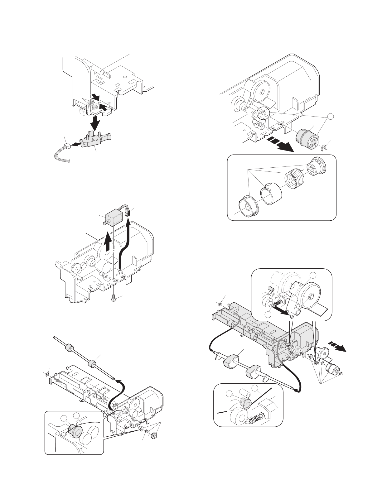
2. Disassembly and assembly
No. Part name Ref.
A Sensor PWB
B Pickup solenoid
C Clutch
D Manual paper feed roller, pickup roller
EBelt
F SPF motor
G Paper entry sensor
H PS roller
I Paper exit roller
Pickup unit removal
1) Remove three fixing pawls from the bottom of the machine.
2) Remove the front cover and the rear cover.
2
2
1) Remove the belt, the paper feed frame Spring, and two harnesses.
2) Remove the pickup unit.
1
1
2
3
4
3
1
1
1
* When installing the parts, be careful of the hole position of the paper
frame Spring.
AR-SP5 AR-SP5 3 - 2
Page 15
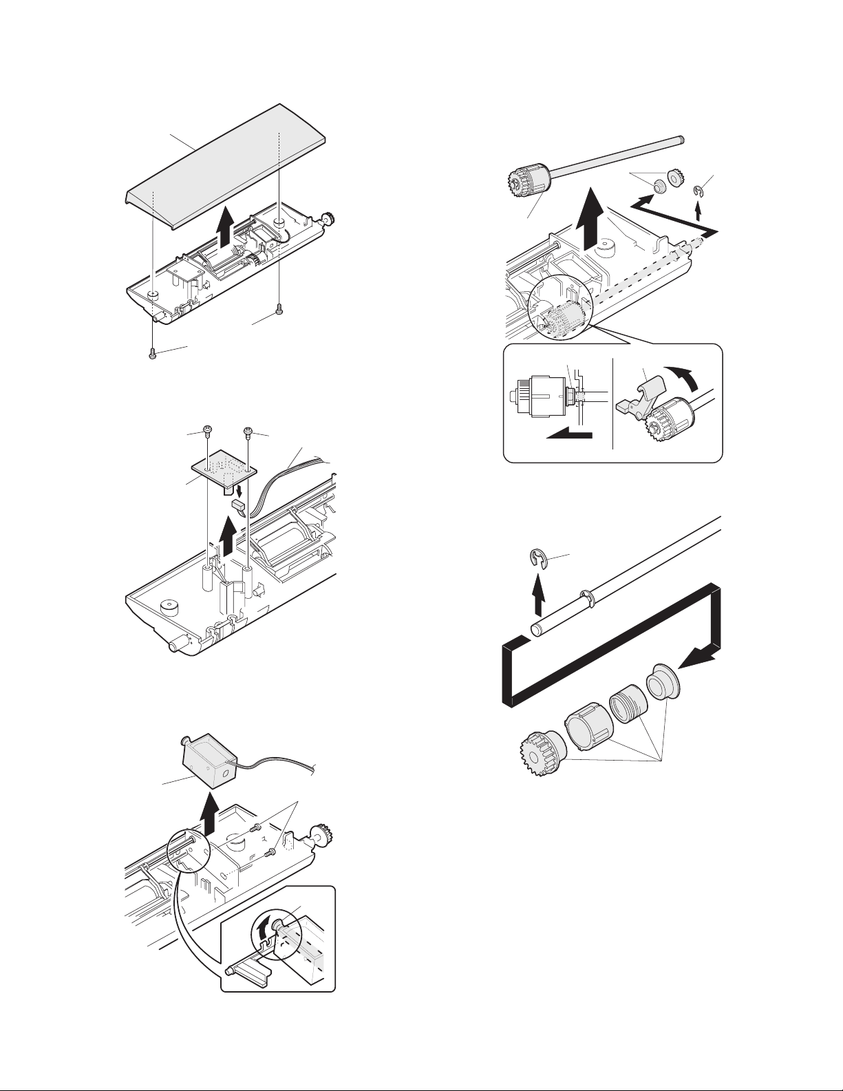
A. Sensor PWB
1) Remove two screws from the bottom of the pickup unit.
2) Remove the upper cover.
2
C. Clutch
1) Remove the E-ring.
2) Remove the pulley and bush.
3) Slide the bush in the arrow direction.
4) Lift the clutch, and 5) remove the clutch.
1
1) Remove two screws.
2) Remove the sensor PWB.
3) Remove the harness.
1
2
2
1
5
1
3
1
3
1) Remove the E-ring.
2) Remove the parts.
1
4
B. Pickup solenoid
1) Remove two screws.
2) Remove the pickup solenoid
2
* When installing, hang iron core A on the solenoid arm.
1
A
2
AR-SP5 AR-SP5 3 - 3
Page 16
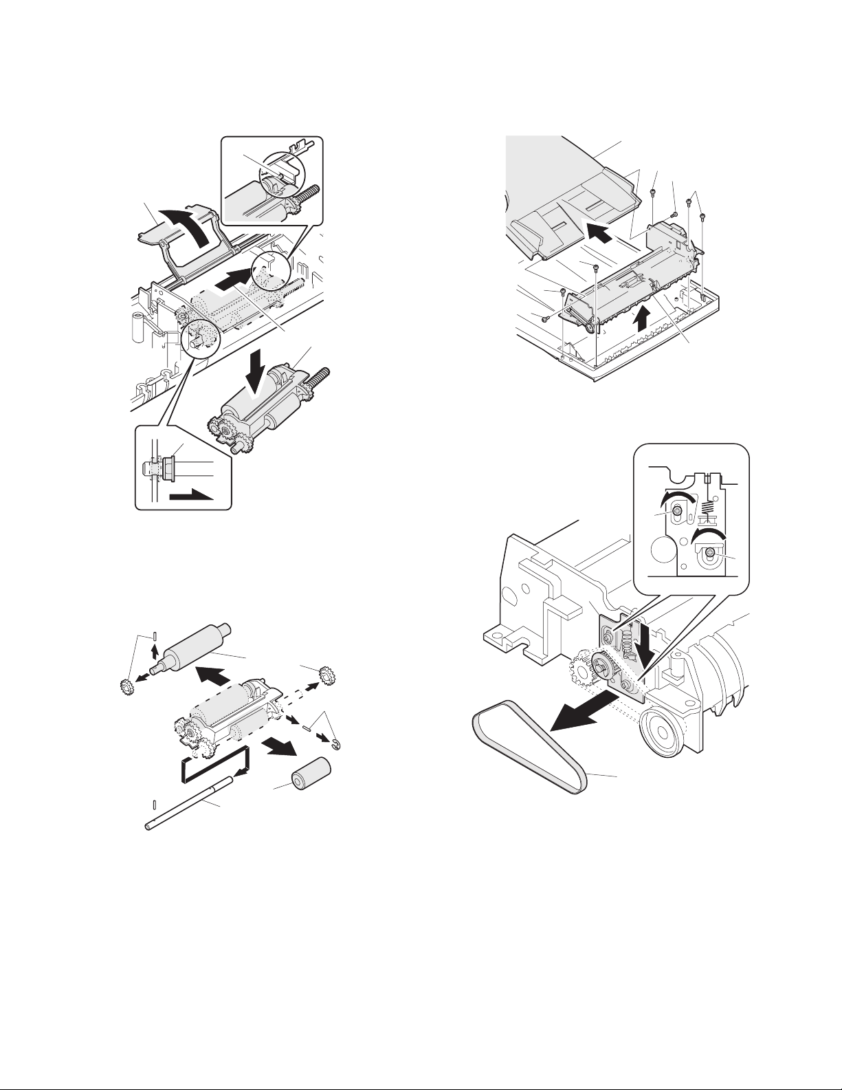
D. Manual paper feed roller, pickup roller
1) Lift the paper stopper.
2) Slide the take-up roller unit.
3) Slide the bushing in the direction of the arrow.
4) Remove the take-up roller unit.
A
1
2
4
3
Transport unit removal
1) Remove two screws.
2) Remove the document tray unit.
3) Remove five screws.
4) Remove the transport unit.
3
3
1
E. Belt
1) Remove the belt.
2
3
1
3
4
* When installing the take-up roller, hang the projection of the take-up
roller unit on the solenoid arm.
1) Remove the parts.
2) Remove the manual paper feed roller.
3) Remove the pickup roller.
4) Remove the parts.
4
3
1
1
1
2
1
1
2
3
AR-SP5 AR-SP5 3 - 4
Page 17
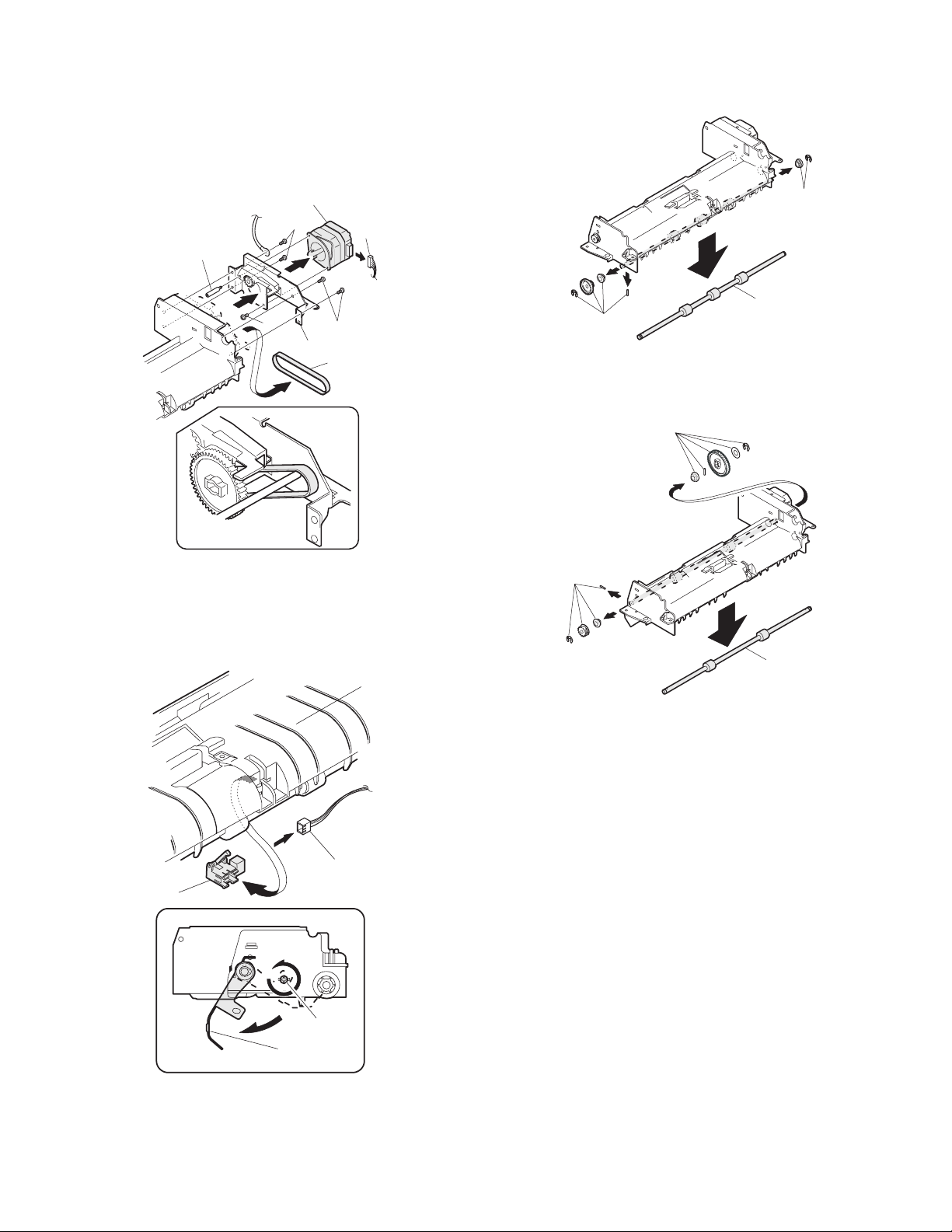
F. SPF motor
1) Remove the harness.
2) Remove four screws.
3) Remove the drive unit.
4) Remove the belt.
5) Remove two screws.
6) Remove the SPF motor.
H. PS roller
1) Remove the parts.
2) Remove the paper supply roller.
5
G. Paper entry sensor
1) Loosen the screw.
2) Open the paper exit paper guide.
3) Remove the paper entry sensor.
4) Remove the harness.
6
2
1
1
2
5
2
3
4
I. Paper exit roller
1) Remove the parts.
2) Remove the paper exit roller.
1
1
1
2
4
3
1
2
AR-SP5 AR-SP5 3 - 5
Page 18
[4] AR-D16
1. Disassembly and assembly
No. Part name Ref.
A Paper sensor
B Cassette detection SW
C Paper feed solenoid
D Transport roller
E Paper feed clutch
F 2nd paper feed roller
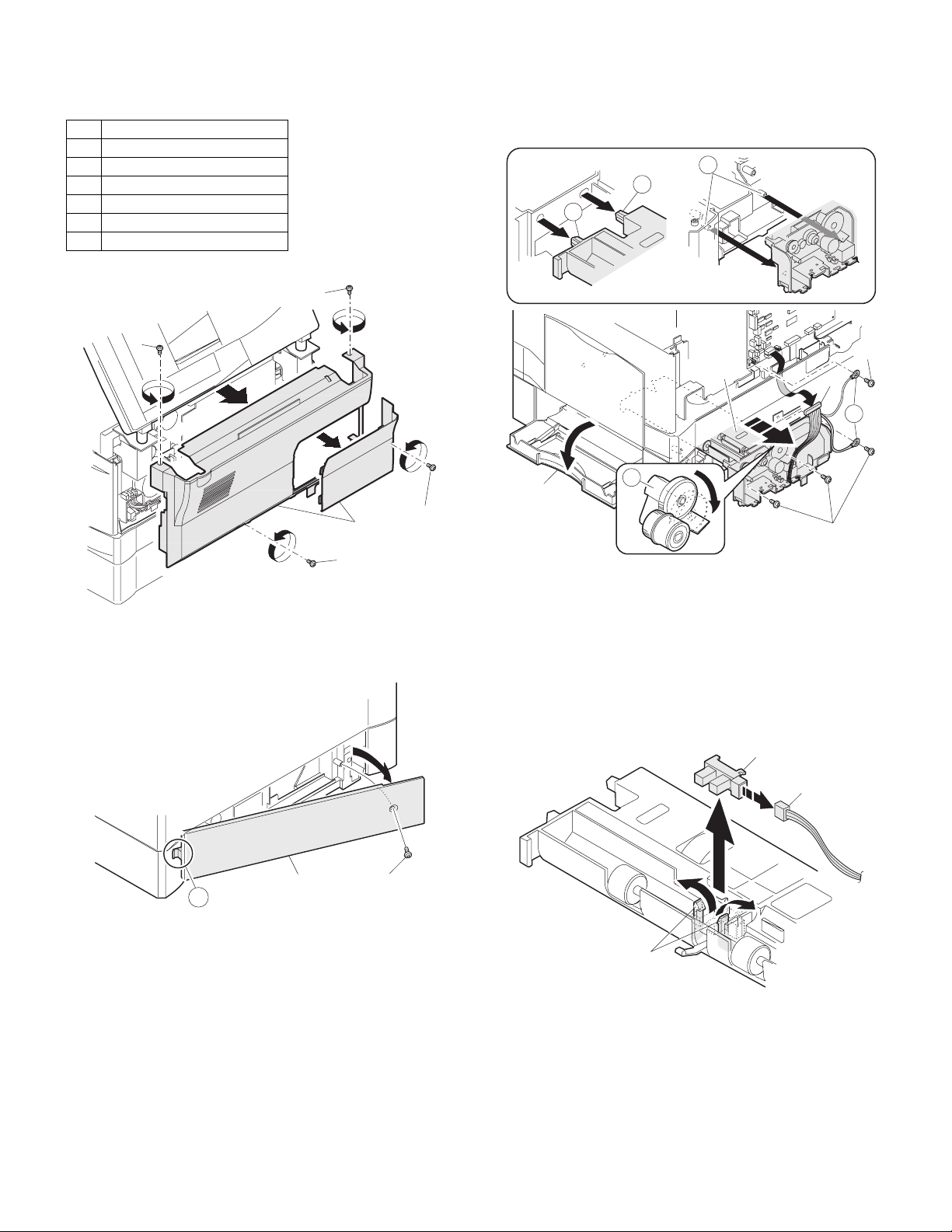
Paper feed unit removal
1)
1) Open the right cabinet.
2) Remove three screws.
3) Remove one connector from MCU.
4) While tilting down the 2nd connection arm A, pull and remove the
paper feed unit toward you.
C
D
D
1)
2)
1)
1) Remove the screw.
2) Remove the rear cover.
* When installing, engage the pawl and install the unit.
2
4
3
B
1
1)
A
2
* When installing, securely insert two bosses C on the machine side
and two bosses D on the paper feed unit side. Be sure to secure the
ground wire B.
* Insert the 2nd page feed.
A. Paper sensor
1) Remove the pawl.
2) Remove the paper sensor.
3) Remove the harness.
2
3
2
1
A
1
AR-SP5 AR-D16 4 - 1
Page 19
B. Cassette detection switch
1) Remove the pawl.
2) Remove the cassette detection switch.
3) Remove the harness.
1
3
2
E. Paper feed clutch
1) Remove the E-ring.
2) Remove the paper feed clutch.
3) Remove the parts.
A
2
1
C. Paper feed solenoid
1) Remove the screw.
2) Remove the connector.
3) Remove the paper feed solenoid.
3
D. Transport roller
1) Remove two E-rings.
2) Remove the transport roller.
4
3
2
* When installing, fit the cut surface A.
F. 2nd paper feed roller
1) Remove the E-ring and the parts.
2) Remove the 2nd paper feed roller.
A
1
1
B
2
1
A
B
3
2
* Install so that the earth spring A is brought into contact over bearing
B.
AR-SP5 AR-D16 4 - 2
D
C
* When installing, hang the 2nd connection arm on the 2nd
connection arm Spring B. Be sure to install so that the earth spring
C is in contact under the bearing D.
1
Page 20
[5] AR-PG2
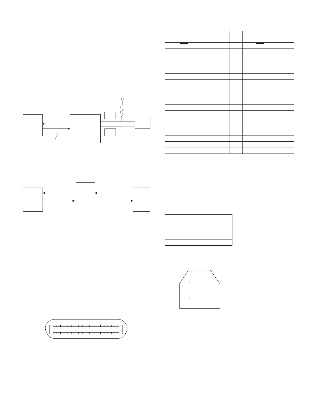
1. Electrical section
A. I/F circuit
(1) General
The I/F circuit is composed of the USB driver and the IEEE1284 driver,
and performs hard interface with the ASIC (MCU PWB).
(2) USB circuit
With the USB driver, the differential signals (analog) of USB are
converted into digital signal, which are sent to the ASIC. In the reverse
procedure, interface between the ASIC (engine) and the host is
performed.
D+
USB driver
ASIC
OE, RCV, VP, VM
Suspend, VMO
VPO
IC401
D-
(3) IEEE1284 circuit
The IEEE1284 driver is used to perform interface between the ASIC
(engine) and the host.
IEEE1284
driver
ASIC
IC403
USB
connector
Centronics
connector
2. Interface
A. PARALLEL INTERFACE
This printer uses a bi-directional parallel interface. Use the supplied
interface cable.
Connector
36-pin DDK 57LE-40360-730B (D29) female connector or equivalent
connector
Cable
Shielded type bi-directional parallel interface
For best results,, use a printer interface cable which is IEEE1284
compliant.
Pin configuration
The pin numbers and signal names are listed in the following table.
Pin
No.
1STB
Signal name
Pin
No.
Signal name
19 GND (STB RET)
2 DATA1 20 GND (DATA1 RET)
3 DATA2 21 GND (DATA2 RET)
4 DATA3 22 GND (DATA3 RET)
5 DATA4 23 GND (DATA4 RET)
6 DATA5 24 GND (DATA5 RET)
7 DATA6 25 GND (DATA6 RET)
8 DATA7 26 GND (DATA7 RET)
9 DATA8 27 GND (DATA8 RET)
10 ACKNLG
28 GND (ACKNLG RET)
11 BUSY 29 GND (BUSY RET)
12 PE (Paper End) 30 GND (PE RET)
13 SLTC 31 INPRM
14 AUTO LF
32 FAULT
15 (NC) 33 (NC)
16 GND (0 V) 34 (NC)
17 FG 35 +5 V
18 +5 V 36 SLTC IN
B. USB INTERFACE
Connector
4-pin DDK DUSB-BRA42-T11
Type-B connector
Cable
Shielded twisted pair cable
(2 m (6 feet) Max.: high-speed transmission equivalent)
Pin configuration
The pin numbers and signal names are listed in the following table.
Pin No. Signal name
1+5V
2–DATA
3+DATA
4GND
2
1
18
1
36 19
34
AR-SP5 AR-PG2 5 - 1
Page 21
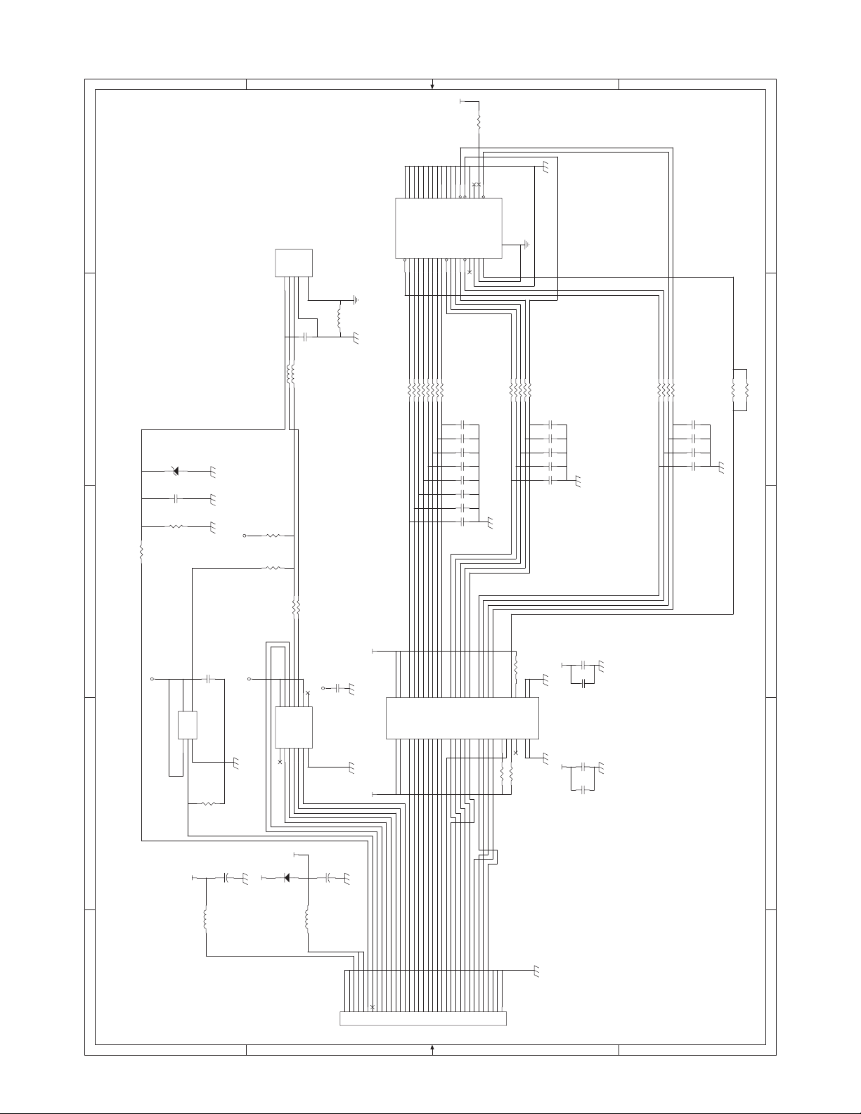
3. Circuit diagram
5V2
3.3KJ
R420
E
31
34
36
32
30
26
27
28
20
21
D-GND
D-GND
Data 02Data 1
3
22
23
D-GND
D-GND
Data 2
4
5
Data 3
25
D-GND
D-GND
D-GND24D-GND
Data 5
Data 6
Data 46Data 7
7
8
9
29
D-GND
/ACK10BUSY11PE
D-GND
D-GND
12
/INIT
13
33
NC
D-GND
/FAULT
SG
NC15SLCT
/AUTO FD
16
14
35
HLHIN
FG
17
/SLCT IN
Shield
PLHOUT
18
IEEE1284_CN
F.G
+5V1D-2D+3GND4Shield
CN402
USB_CN
CN401
19
D-GND
/D STB
1
E
F.G
L405
C403
D
L404 N.M.
L403 N.M.
ZENER_6.2V
D402
100p
C426
R429
10kJ
R430 24J
3.3V1
R404
R423
N.M.(1.5kJ)
1.5kJ
C
beads
0.1u
D
22J
R406
22J
R407
22J
22J
22J
22J
R408
R409
R410
R411
22J
R412
22J
R413
C411
C410
C409
C408
C407
C406
C405
C404
22J
22J
22J
R414 22J
R415 22J
R416
R417
R421
C418
100p
100p
100p
100p
100p
100p
100p
100p
C415
C414
C413
C412
100p
100p
100p
100p
100p
22J
R405
22J
R418
22J
R419
22J
R422
C419
C417
C416
C422
100p
100p
330p
100p
10kJ
R427
N.M.
R401
C
B
A
3.3V1
I/F PWB
4 4
IC402
5
4
Y
VCC
A1GND
B
3
2
3.3V1
0.1u
C420
NC7S08M5
R428
10kJ
L402
N.M.
+
C402
47u/16V
3.3V1
5V2
R402 24J
R403 24J
11
10
9
13
12
14
D-
D+
VCC
VPO
VMO
SPEED
NC1OE#2RCV3VP4VM5SUSPEND6GND
5V1
D401
11EQS06
L401
3.3V1
8
NC
7
IC401 USB_Transceiver
+
C401
N.M.
C421
47u/16V
CN403
C423
0.1u
5V1
0.1u
74LVX161284
3.3V1
C424
C427
C425
0.1u
0.1u
B
0.1u
3.3V1 5V1
IC403
31
42
Vcc-cable
Vcc-cable
Vcc
7
18
33
B832B7
B635B536B437B3
A716A817Vcc
14
46
38
41
47
B240B1
Y9
Y1343Y1244Y1145Y10
A92A103A114A125A13
A18A2
A311A412A513A6
6
9
30
29
C1726C1627C1528C14
HD
A1420A1521A1622A1723HLH
DIR
1
19
48
R426 10kJ
R425 10kJ
PLH
PLHin
R424 10kJ
25
24
HLHin
34
39
GND
GND
GND
GND
10
15
A
D_CONT
VMO
5VEN
VPO
USB_IN
5VEN
3.3V
OEN
VMIN
VPIN
RCV
SUSPEND
PARAAD0
PARAAD1
PARAAD3
PARAAD2
PARAAD5
PARAAD6
PARAAD4
35
3 3
PARAAD7
REV
/FAULT
/ACK
BUSY
10111213141516171819202122232425262728293031323334
/STB
/SLCTIN
IF_DET
/AUTOFD
/INTI
SLCT
PE
123456789
35FE-BT-VK-N
2 2
1 1
AR-SP5 AR-PG2 5 - 2
Page 22

Page 23

q
PARTS GUIDE
CODE:00ZARSP5///P1
AR-SP5
AR-D16
MODEL
CONTENTS
1
AL-12PK (Except USA) (Packing material & accessories)
AR-PG2 (USA) (Packing material & accessories)
2
AL-12PK (IF PWB)
AR-PG2 (IF PWB)
3
AR-D16 (Packing material & Accessories)
4
AR-D16 (2nd frame unit)
5
AR-D16 (2nd paper feeding unit)
6
AR-SP5 (Packing material & Accessories)
7
AR-SP5 (Exteriors)
8
AR-SP5 (Pick up unit)
AR-PG2 ( )
AL-12PK( )
USA
Except
USA
9
AR-SP5 (Transport unit)
■
Index
Because parts marked with " !" is indispensable for the machine safety maintenance and operation, it must
Be replaced with the parts specific to the product specification.
This document has been published to be used for
SHARP CORPORATION
after sales service only.
The contents are subject to change without notice.
Page 24
DEFINITION
The definition of each Rank is as follows and also noted in the list
A: Parts necessary to be stocked as High usage parts.
B: Parts necessary to be stocked as Standard usage parts.
C: Low usage parts.
D: Parts necessary for refurbish.
E: Unit parts recommended to be stocked for efficient after sales service.
Please note that the lead time for the said parts may be longer than normal parts.
S: Consumable parts.
Please note that the following parts used in Copier under the same description are classified into A or B Rank depending upon
the place used.
Example: Gear made of Metal, Sprocket, Bearing, Belt made of Rubber, Spring clutch mechanism.
ARank : The parts which may be with the revolution or loading.
BRank : Parts similar to A Rank parts, but are not included in Rank A.
Because parts marked with "!" is indispensable for the machine safety maintenance and operation, it must be replaced with
the parts specific to the product specification.
F Other than this Parts Guide, please refer to documents Service Manual(including Circuit Diagram)of this model.
F Please use the 13 digit code described in the right hand corner of front cover of the document, when you place an order.
F For U.S. only-Use order codes provided in advertising literature. Do not order from parts department.
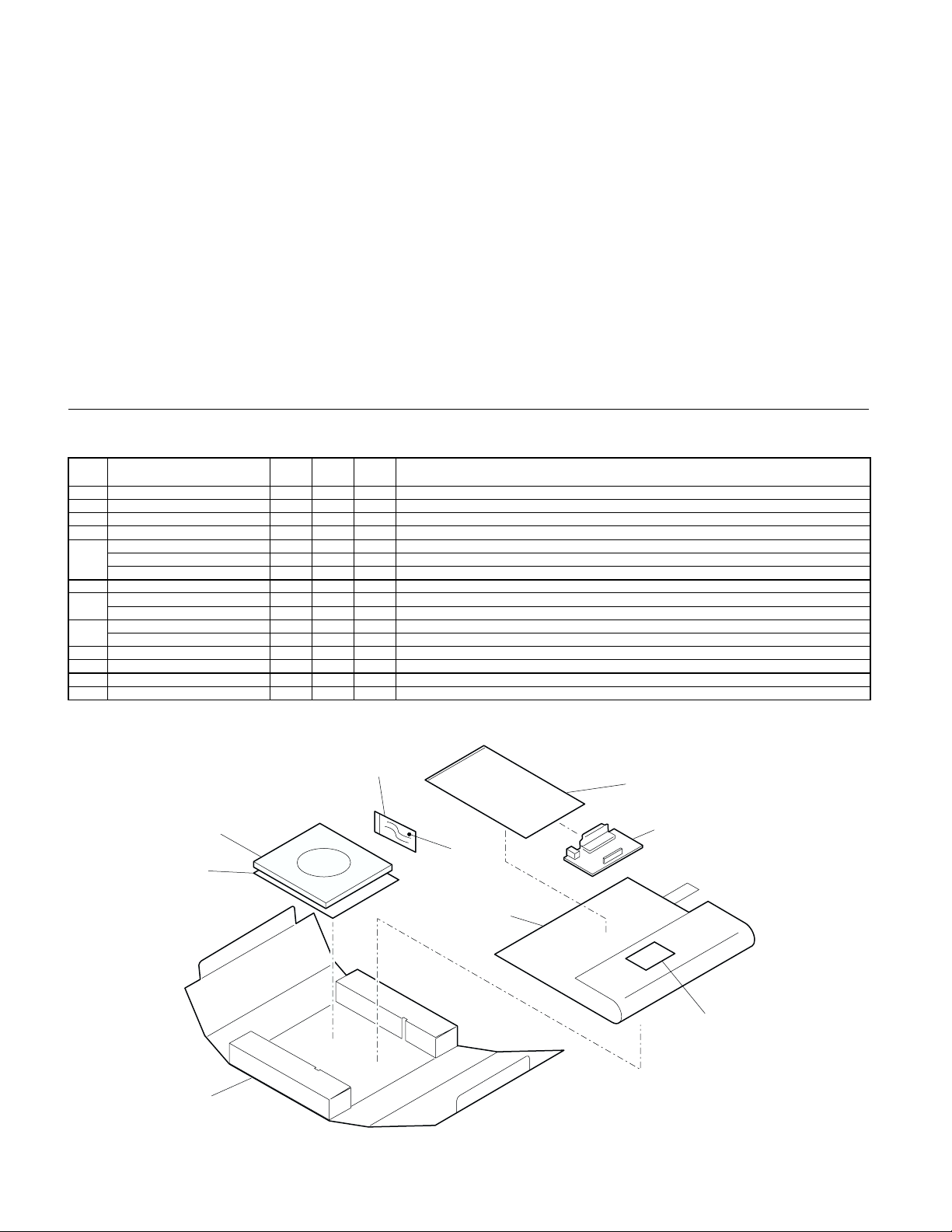
AL-12PK(Except USA)/AR-PG2(USA) (Packing material & accessories)
1
PRICE
NEW
NO. PARTS CODE
1 SPAK-548ECCZZ AB D Vinyl bag
2 SPAKA5824FCZZ AF D ARMM protect sheet
3 DHAI-0283QSZZ AD C MCU-I/Fharness
4 SSAKH0130QCZZ AA D Vinyl bag(80×140mm)
XBBSE30P08000 AA C Screw(3×8)
5
UKOGD0001QSZZ AG C Screwdriver
RCORF1028LCZZ AP C Core
6 CDSKA0019QS32 AL N D CD-ROM
TCADZ0199QSZZ AF N D Card (AL-12PK Except USA)
7
TCADZ0203QSZZ AG N D Card (AR-PG2 USA)
SPAKC0412RS12 AG N D Packing case (AL-12PK Except USA)
8
SPAKC0424RSZZ AG N D Packing case (AR-PG2 USA)
RANK
MARK
PART
RANK
DESCRIPTION
AL-12PK(Except USA)/AR-PG2(USA) (Packing material & accessories)
1
4
6
5
7
2
8
1
IF PWB
3
PRP00939
– 1 –
Page 25
AL-12PK/AR-PG2 (IF PWB)
2
PRICE
NEW
NO. PARTS CODE
1 DHAI-0310QSZZ AB C IF GND harness
2 QCNCW0078QSZZ AF C Connector(35Pin)(35FE-BT-VK-N) [CN403]
3 QSOCN0002ESZZ AH C Connector(36Pin)(RBE42-36K1153) [CN401]
4 QSOCN0005ESZZ AE C Connector(UBR23-4K2200) [CN402]
5 RFILN0010QSZZ AB C Coil(BLM18BB121SN1D) [L405]
6 RH-DX0001ESZZ AC B Diode(11EQS06-TA1B2) [D401]
VCCCCY1HH101J AA C Capacitor(50WV 100pF/1608Type/CH) [C404∼415,417∼419]
7
VCCCCY1HH101J AA C Capacitor(50WV 100pF/1608Type/CH) [C421,426]
8 VCCCCY1HH331J AB C Capacitor(50WV 330pF) [C416]
9 VCEAGA1CW476M AB C Capacitor(16WV 47µF) [C401,402]
VCKYCY1CF104Z AA C Capacitor(16WV 0.1µF) [C403,420,421,423]
10
VCKYCY1CF104Z AA C Capacitor(16WV 0.1µF) [C424,425,427]
11 VHEUDZS6.2B-1 AC B Zener diode(UDZS6.2B) [D402]
12 VHI74LVX16128 AP B IC(74LVX16128) [IC403]
13 RH-IX0005ESZZ AE B IC(IX0005ES) [IC402]
14 VHIUSB11AMX-1 AH B IC(USB1T11AMX) [IC401]
15 VRS-CY1JD000J AA C Resistor(1/16W 0Ω ±5%) [L403,404]
16 VRS-CY1JD103J AA C Resistor(1/16W 10KΩ ±5%) [R424∼429]
17 VRS-CY1JD152J AA C Resistor(1/16W 1.5KΩ ±5%) [R423]
18 VRS-CY1JD220J AA C Resistor(1/16W 22Ω ±5%) [R405∼419,421,422]
19 VRS-CY1JD240J AA C Resistor(1/16W 24Ω ±5%) [R402,403,430]
20 VRS-CY1JD332J AA C Resistor(1/16W 3.3KΩ ±5%) [R420]
AR-D16 (Packing material & Accessories)
3
NO. PARTS CODE
1 TTAG-0002QSZZ AB C Tray rotation tag
2 LHLDW1226FCZZ AB C Holder
3 TCADZ0204QSZZ AE N D Card
4 SPAKA5108FCZZ AF D Packing add
5 SSAKH0021SCZZ AC D Vinyl bag
6 SPAKC0422RSZZ AT N D Packing case
7 XEBSE40P12000 AA C Screw(4×12)
8 XEBSE40P16000 AA C Screw(4×16)
9 SSAKA2011KCZZ AA D Vinyl bag(60×100mm)
RANK
PRICE
RANK
MARK
NEW
MARK
PART
RANK
PART
RANK
DESCRIPTION
DESCRIPTION
AR-D16 (Packing material & Accessories)
3
3
4
6
7
9
8
5
1
2
PRP00940
– 2 –
Page 26

AR-D16 (2nd frame unit)
4
PRICE
NEW
NO. PARTS CODE
1 GCOVA0005QSJZ AL D Front cover
2 XEBSE40P12000 AA C Screw(4×12)
3 GCOVA0006QSJZ AN D Rear cover
4 PGIDM0016QSJZ AY C Guide L
5 XEBSD40P12000 AA C Screw(4×12)
6 LPLTM0036QSZZ AF C 2ND joint plate R
7 GLEGG0064FCZZ AC D Rubber foot
8 PGIDM0015QSJZ AY C Guide R
9 MSPRC2544FCZZ AC C 2ND transport cover spring
10 GCOVA0007QSZZ AK D Transport cover
11 NROLP1060FCZZ AF C U-turn roller
12 MSPRT0112QSZ1 AC C Transport collar spring
13 MARMP0012QSZZ AD C 2ND door arm
14 GCOVA0008QSJZ AK D Right cover
15 XHBSD40P08000 AA C Screw(4×8)
16 XEBSE40P16000 AA C Screw(4×16)
17 CFRM-0009RS55 BF N E 2nd paper feeding unit
AR-D16 (2nd frame unit)
4
RANK
MARK
PART
RANK
2
DESCRIPTION
2
16
1
2
2
15
3
5
5
4
5
6
17
9
8
7
9
13
7
11
12
16
10
16
11
12
13
14
– 3 –
16
PRP00941
Page 27

AR-D16 (2nd paper feeding unit)
5
PRICE
NEW
NO. PARTS CODE
1 NROLP0019QSZ1 AP C Transport roller
2 NBRGC0016QSZZ AD C Bearing(B-F5-13)
3 XRESP40-06000 AA C E-ring
5 NGERH0992FCZZ AB C Gear(20T)
6 XPSSP20-07000 AA C Spring pin(φ2-7)
7 LBOSZ1031FCZZ AC C Clutch boss
8 MSPRC0161QSZZ AF C Clutch spring
9 PPIPP0007QSZZ AD C Clutch pipe
10 NGERH1132FCZZ AH C Clutch gear(29T)
11 NGERH1207FCZZ AF C Joint gear(40T)
12 MARMP0229FCZZ AE C Joint arm
13 MSPRC2545FCZZ AB C 2nd joint arm spring
14 DHAI-0266QSZZ AK N C 2nd harness
15 VHPGP1A71A1-1 AG B Photo sensor(GP1A71A1)
16 MLEVP0033QSZZ AF C PPDI actuator
17 MSPRD0058QSZZ AG C Earth spring
18 RPLU-0010QSZZ AN B PF solenoid
19 XHBSD30P06000 AA C Screw(3×6)
20 PTME-0008QSZZ AD C PF clutch pawl
21 MSPRC2546FCZZ AB C 2nd clutch pawl spring
22 NGERH0041QSZZ AF C 2nd gear ID(18T/26T)
23 NGERH0990FCZZ AB C Gear(16T)
24 QSW-B0003QSZZ AF B Tray detect switch
25 CROLP0015QS01 AU C Paper feeding roller
26 LFRM-0009QSZ2 AQ D Paper feeding frame
31 LBNDJ0013FCZ1 AA C Wire band
(Unit)
901 CFRM-0009RS55 BF N E 2nd paper feeding unit
RANK
MARK
PART
RANK
DESCRIPTION
AR-D16 (2nd paper feeding unit)
5
24
14
14
15
26
1
16
2
18
6
5
3
17
13
11
12
8
9
2
10
3
3
7
20
22
21
3
23
23
31
19
24
14
3
25
PRP00942
– 4 –
Page 28

AR-SP5 (Packing material & Accessories)
6
PRICE
NEW
NO. PARTS CODE
1 SSAKA0019SCZZ AA D Vinyl bag(120×180mm)
2 TCADZ0205QSZZ AE N D Inst.manual
4 SSAKH3012KCZZ AD D Vinyl bag(790×740mm)
5 SPAKA0219QSZZ AP D Packing add L
6 SPAKA0220QSZZ AQ D Packing add R
7 SPAKC0423RSZZ AT N D Packing case
8 SPAKA0242QSZZ AL D OC protect sheet
11 XHBSE30P08000 AA C Screw(3×8)
12 SSAKA2011KCZZ AA D Vinyl bag(60×100mm)
13 DUNT-0280RSZZ AU N E Book sensor unit
14 PGIDM0019QSJZ AH C Hinge guide L
15 PGIDM0020QSJZ AH C Hinge guide R
16 GCOV-0045QSZZ AG D Rear cover SPF
100 PCUSS0025QSZZ AQ D OC mat
AR-SP5 (Packing material & Accessories)
6
RANK
MARK
PART
RANK
1
DESCRIPTION
14
15
5
11
2
12
12
13
12
4
8
6
16
– 5 –
7
PRP00943
Page 29

AR-SP5 (Exteriors)
7
PRICE
NEW
NO. PARTS CODE
1 LSOU-0035QSZZ AR D Original tray
2 LPLTP0011QSJZ AH C Control plate F
3 LPLTP0012QSJZ AH C Control plate R
4 NGERR0377FCZZ AD C Manual feeding rack gear
5 XEPSD30P08X00 AA C Screw(3×8X)
6 NGERH0193FCZZ AB C Manual feeding gear
7 MSPRP0059QSZZ AD C Control plate spring
11 CFRM-0011RS58 BF E SPF pick up unit
13 XEBSD40P10000 AA C Screw(4×10)
14 CFRM-0013RS57 BP E SPF transport unit
15 LBNDJ0013FCZ1 AA C Wire band
16 PSHEZ0384QSZZ AD C Base tray sheet
17 PSHEP0063QSZZ AC C Transport sheet
18 MSPRP0113QSZ1 AD C Earth spring
19 PSHEZ0379QSZZ AD C OC sheet
20 XEBSD30P08000 AA C Screw(3×8)
21 MHNG-0017QSZZ AQ C SPF hinge
22 XEBSE40P14000 AA C Screw(4×14)
23 NROLP0011QSZZ AD C Delivery roller
24 PSPO-0001QSZZ AB C Sponge
25 NSFTZ0010QSZZ AE C Delivery shaft
26 MSPRT0061QSZZ AC C Delivery spring
27 MSPRP0060QSZZ AD C Transport spring
28 NROLP0010QSZZ AD C Transport roller
29 NSFTZ0009QSZZ AE C Transport shaft
30 LPLTM0096QSZZ AF C Base tray reinforce plate
31 LX-BZ0016QSZZ AC C Screw(3×8)
33 LSOU-0005QSJ4 BA D Base tray
34 PCUSS0025QSZZ AQ D OC mat
35 PSHEZ0102QSZZ AD C Motor pressure sheet
36 PSHEZ0112QSZZ AE C Delivery earth sheet SPF
37 MSPRC0149QSZZ AC C PS earth spring SPF
38 PSHEZ0386QSZZ AB D Rear side mylar A
39 PSHEZ0387QSZZ AB D Rear side mylar B
40 PSHEZ0388QSZZ AD C OC sheet mylar 2
45 PSHEZ0383QSZZ AC C Book detect sheet
501 CSOU-0035RS51 AZ E SPF original tray unit
RANK
MARK
PART
RANK
DESCRIPTION
AR-SP5 (Exteriors)
7
2
501
11
1
3
15
13
22
14
13
4
4
5
5
6
45
22
7
5
13
17
17
16
39
13
35
38
23
31
39
25
24
20
28
26
20
31
28
27
24
30
31
37
20
23
27
31
36
29
22
18
21
40
31
34
33
21
22
19
PRP00944
– 6 –
Page 30

AR-SP5 (Pick up unit)
8
PRICE
NEW
NO. PARTS CODE
1 GCAB-0008QSJZ AM D Open and shut exterior
2 PSPO-0002QSZZ AC C Stopper sponge
4 MARMP0003QSZ1 AD C Stopper arm
5 LSTPP0001QSZZ AD C Paper stopper R
6 XEBSD30P08000 AA C Screw(3×8)
7 CPWBF0009RS51 AG E SPF sensor PWB
8 DHAI-0293QSZZ AE C Sensor harness
9 MLEVP0009QSZZ AD C Set detect lever ACT
10 MLEVP0010QSZZ AE C Open and shut detect lever ACT
11 RPLU-0004QSZ1 AQ B PU solenoid
12 XBPSD30P06KS0 AA C Screw(3×6KS)
13 MARMP0002QSZZ AD C Solenoid arm
14 MSPRT0067QSZ1 AB C Solenoid arm spring
15 XRESP40-06000 AA C E-ring
16 NGERH0073QSZZ AE C Clutch gear(20T)
17 PPIPP0008QSZZ AD C Clutch sleeve
18 MSPRC1316FCZ1 AE C MF clutch spring B
19 LBOSZ1851FCZZ AC C STK clutch boss
20 LBSHZ0303FCZZ AC C M bushing C
21 NSFTZ0012QSZZ AG C Clutch shaft
22 LBSHZ0006QSZZ AC C M Bushing 2
23 NPLYZ0010QSZZ AE C 20MXL pulley
24 XRESP30-06000 AA C E-ring
25 MSPRT0066QSZ1 AC C Clutch pawl spring
26 PTME-0019QSZZ AD C Clutch pawl
27 NROLP0024QSZ1 AH C Pick up roller
28 NGERH0990FCZZ AB C Gear(16T)
29 XPSSP20-07000 AA C Spring pin(φ2-7)
30 NGERH0992FCZZ AB C Gear(20T)
31 NROLR0922FCZZ AR C Manual feeding roller
32 NSFTZ0011QSZ2 AF C PF shaft
33 MSPRC0115QSZZ AB C Paper feeding spring
34 MARMP0004QSZZ AF C Pick up arm
35 LFRM-0011QSJ2 AL D Paper feedind frame
36 MSPRD0114QSZ1 AD C PF frame spring
(Unit)
901 CFRM-0011RS58 BF E SPF pick up unit
RANK
MARK
PART
RANK
DESCRIPTION
AR-SP5 (Pick up unit)
8
6
7
8
36
1
2
15
11
17
4
16
18
19
21
15
14
5
13
20
12
23
24
20
9
6
6
10
35
12
6
– 7 –
29
22
25
28
26
30
29
27
30
34
30
29
31
33
15
32
PRP00945
20
Page 31

AR-SP5 (Transport unit)
9
PRICE
NEW
NO. PARTS CODE
1 PGIDM0042QSJZ AL C U-turn paper guide
2 XEBSD30P12000 AA C Screw(3×12)
3 LX-BZ0012QSZZ AC C Screw
4 NGERH0972FCZZ AB C Gear(27T)
5 MARMP0001QSZZ AF C Drive arm
6 XBPSD30P05K00 AA C Screw(3×5K)
7 RMOTP0013QSZZ BB B SPF motor
9 DHAI-0290QSZZ AN C SPF interface harness
10 LBNDJ0013FCZ1 AA C Wire band
11 MSPRT0064QSZ1 AC C Drive arm spring
12 LFRM-0013QSZZ AG C Drive frame
13 XRESP50-06000 AA C E-ring
14 PSHEP3029FCZZ AA C Flange sheet DUP2
15 NBLTT0006QSZZ AG B Belt(83MXL4.8)
16 NGERH0047QSZZ AF C Gear(48T/15T)
17 LPINS0019QSZZ AB C Spring pin(φ2.5-9)
18 NBRGC0017QSZZ AC C Bearing
19 NBRGM0501FCZZ AB C Metal D
20 LFRM-0012QSZZ AD C Frame R
21 PSHEZ0039QSZZ AG C Sheet
22 LPLTP0013QSZZ AD C Plate
23 MSPRC0062QSZZ AC C Pressure spring
24 MSPRP0065QSZZ AD C Open and shut lock spring
25 PSHEZ2174FCZZ AB C Paper feeding sheet
26 NPLYZ0146FCZZ AB C 22MXL pulley
27 NBLTT0003QSZZ AG B Belt(B75MXL4.8)
28 JKNBZ0004QSZZ AD C JAM release knob
29 MSPRC0063QSZZ AB C Delivery paper guide spring
30 PGIDM0024QSZ3 AN C Transport paper guide
31 RDTCT0004QSZZ AL B Inlet detect sensor
32 NROLM0023QSZ1 AP C Delivery roller
33 PBRSR0003QSZ2 AG B Discharge brush
34 PGIDH0029QSZZ AL C Delivery paper guide
35 PSHEP0044QSZZ AF C White sheet
36 NROLM0022QSZ1 AL C PS roller
37 PCOVP0037QSJZ AH D Front cover
38 PCOVP0038QSJ1 AL D Rear cover
39 XEBSE30P10000 AA C Screw(3×10)
40 CPLTM0298QS01 AF C SPF tension plate
41 MSPRT0294QSZZ AC C SPF tension spring
(Unit)
901 CFRM-0013RS57 BP E SPF transport unit
RANK
MARK
PART
RANK
DESCRIPTION
AR-SP5 (Transport unit)
9
13
41
26
13
39
17
26
13
27
13
19
40
28
17
24
37
19
29
2
25
32
22
23
30
31
21
38
2
1
13
18
17
16
14
2
3
15
4
9
7
10
39
11
5
12
6
39
13
24
19
20
29
36
35
34
33
PRP00946
– 8 –
Page 32

■
Index
PARTS CODE NO.
[C]
CDSKA0019QS32
CFRM-0009RS55
CFRM-0011RS58
CFRM-0013RS57
CPLTM0298QS01
CPWBF0009RS51
CROLP0015QS01
CSOU-0035RS51
DHAI-0266QSZZ
DHAI-0283QSZZ
DHAI-0290QSZZ
DHAI-0293QSZZ
DHAI-0310QSZZ
DUNT-0280RSZZ
GCAB-0008QSJZ
GCOV-0045QSZZ
GCOVA0005QSJZ
GCOVA0006QSJZ
GCOVA0007QSZZ
GCOVA0008QSJZ
GLEGG0064FCZZ
JKNBZ0004QSZZ
LBNDJ0013FCZ1
LBOSZ1031FCZZ
LBOSZ1851FCZZ
LBSHZ0006QSZZ
LBSHZ0303FCZZ
LFRM-0009QSZ2
LFRM-0011QSJ2
LFRM-0012QSZZ
LFRM-0013QSZZ
LHLDW1226FCZZ
LPINS0019QSZZ
LPLTM0036QSZZ
LPLTM0096QSZZ
LPLTP0011QSJZ
LPLTP0012QSJZ
LPLTP0013QSZZ
LSOU-0005QSJ4
LSOU-0035QSZZ
LSTPP0001QSZZ
LX-BZ0012QSZZ
LX-BZ0016QSZZ
MARMP0001QSZZ
MARMP0002QSZZ
MARMP0003QSZ1
MARMP0004QSZZ
MARMP0012QSZZ
MARMP0229FCZZ
MHNG-0017QSZZ
MLEVP0009QSZZ
MLEVP0010QSZZ
MLEVP0033QSZZ
MSPRC0062QSZZ
MSPRC0063QSZZ
MSPRC0115QSZZ
MSPRC0149QSZZ
MSPRC0161QSZZ
MSPRC1316FCZ1
MSPRC2544FCZZ
MSPRC2545FCZZ
MSPRC2546FCZZ
MSPRD0058QSZZ
MSPRD0114QSZ1
MSPRP0059QSZZ
MSPRP0060QSZZ
MSPRP0065QSZZ
MSPRP0113QSZ1
"
"
"
[D]
[G]
[J]
[L]
"
"
[M]
PRICE
NEW
MARK
PART
RANK
RANK
1- 6 AL N D
4- 17 BF N E
5- 901 BF N E
7- 11 BF E
8- 901 BF E
7- 14 BP E
9- 901 BP E
9- 40 AF C
8- 7 AG E
5- 25 AU C
7- 501 AZ E
5- 14 AK N C
1- 3 AD C
9- 9 AN C
8- 8 AE C
2- 1 AB C
6- 13 AU N E
8- 1 AM D
6- 16 AG D
4- 1 AL D
4- 3 AN D
4- 10 AK D
4- 14 AK D
4- 7 AC D
9- 28 AD C
5- 31 AA C
7- 15 AA C
9- 10 AA C
5- 7 AC C
8- 19 AC C
8- 22 AC C
8- 20 AC C
5- 26 AQ D
8- 35 AL D
9- 20 AD C
9- 12 AG C
3- 2 AB C
9- 17 AB C
4- 6 AF C
7- 30 AF C
7- 2 AH C
7- 3 AH C
9- 22 AD C
7- 33 BA D
7- 1 AR D
8- 5 AD C
9- 3 AC C
7- 31 AC C
9- 5 AF C
8- 13 AD C
8- 4 AD C
8- 34 AF C
4- 13 AD C
5- 12 AE C
7- 21 AQ C
8- 9 AD C
8- 10 AE C
5- 16 AF C
9- 23 AC C
9- 29 AB C
8- 33 AB C
7- 37 AC C
5- 8 AF C
8- 18 AE C
4- 9 AC C
5- 13 AB C
5- 21 AB C
5- 17 AG C
8- 36 AD C
7- 7 AD C
7- 27 AD C
9- 24 AD C
7- 18 AD C
PARTS CODE NO.
MSPRT0061QSZZ
MSPRT0064QSZ1
MSPRT0066QSZ1
MSPRT0067QSZ1
MSPRT0112QSZ1
MSPRT0294QSZZ
[N]
NBLTT0003QSZZ
NBLTT0006QSZZ
NBRGC0016QSZZ
NBRGC0017QSZZ
NBRGM0501FCZZ
NGERH0041QSZZ
NGERH0047QSZZ
NGERH0073QSZZ
NGERH0193FCZZ
NGERH0972FCZZ
NGERH0990FCZZ
"
NGERH0992FCZZ
"
NGERH1132FCZZ
NGERH1207FCZZ
NGERR0377FCZZ
NPLYZ0010QSZZ
NPLYZ0146FCZZ
NROLM0022QSZ1
NROLM0023QSZ1
NROLP0010QSZZ
NROLP0011QSZZ
NROLP0019QSZ1
NROLP0024QSZ1
NROLP1060FCZZ
NROLR0922FCZZ
NSFTZ0009QSZZ
NSFTZ0010QSZZ
NSFTZ0011QSZ2
NSFTZ0012QSZZ
[P]
PBRSR0003QSZ2
PCOVP0037QSJZ
PCOVP0038QSJ1
PCUSS0025QSZZ
"
PGIDH0029QSZZ
PGIDM0015QSJZ
PGIDM0016QSJZ
PGIDM0019QSJZ
PGIDM0020QSJZ
PGIDM0024QSZ3
PGIDM0042QSJZ
PPIPP0007QSZZ
PPIPP0008QSZZ
PSHEP0044QSZZ
PSHEP0063QSZZ
PSHEP3029FCZZ
PSHEZ0039QSZZ
PSHEZ0102QSZZ
PSHEZ0112QSZZ
PSHEZ0379QSZZ
PSHEZ0383QSZZ
PSHEZ0384QSZZ
PSHEZ0386QSZZ
PSHEZ0387QSZZ
PSHEZ0388QSZZ
PSHEZ2174FCZZ
PSPO-0001QSZZ
PSPO-0002QSZZ
PTME-0008QSZZ
PTME-0019QSZZ
[Q]
QCNCW0078QSZZ
QSOCN0002ESZZ
QSOCN0005ESZZ
QSW-B0003QSZZ
[R]
RCORF1028LCZZ
RDTCT0004QSZZ
RFILN0010QSZZ
RH-DX0001ESZZ
RH-IX0005ESZZ
PRICE
NEW
MARK
PART
RANK
RANK
7- 26 AC C
9- 11 AC C
8- 25 AC C
8- 14 AB C
4- 12 AC C
9- 41 AC C
9- 27 AG B
9- 15 AG B
5- 2 AD C
9- 18 AC C
9- 19 AB C
5- 22 AF C
9- 16 AF C
8- 16 AE C
7- 6 AB C
9- 4 AB C
5- 23 AB C
8- 28 AB C
5- 5 AB C
8- 30 AB C
5- 10 AH C
5- 11 AF C
7- 4 AD C
8- 23 AE C
9- 26 AB C
9- 36 AL C
9- 32 AP C
7- 28 AD C
7- 23 AD C
5- 1 AP C
8- 27 AH C
4- 11 AF C
8- 31 AR C
7- 29 AE C
7- 25 AE C
8- 32 AF C
8- 21 AG C
9- 33 AG B
9- 37 AH D
9- 38 AL D
6- 100 AQ D
7- 34 AQ D
9- 34 AL C
4- 8 AY C
4- 4 AY C
6- 14 AH C
6- 15 AH C
9- 30 AN C
9- 1 AL C
5- 9 AD C
8- 17 AD C
9- 35 AF C
7- 17 AC C
9- 14 AA C
9- 21 AG C
7- 35 AD C
7- 36 AE C
7- 19 AD C
7- 45 AC C
7- 16 AD C
7- 38 AB D
7- 39 AB D
7- 40 AD C
9- 25 AB C
7- 24 AB C
8- 2 AC C
5- 20 AD C
8- 26 AD C
2- 2 AF C
2- 3 AH C
2- 4 AE C
5- 24 AF B
1- 5 AP C
9- 31 AL B
2- 5 AB C
2- 6 AC B
2- 13 AE B
– 9 –
Page 33

PARTS CODE NO.
RMOTP0013QSZZ
RPLU-0004QSZ1
RPLU-0010QSZZ
[S]
SPAK-548ECCZZ
SPAKA0219QSZZ
SPAKA0220QSZZ
SPAKA0242QSZZ
SPAKA5108FCZZ
SPAKA5824FCZZ
SPAKC0412RS12
SPAKC0422RSZZ
SPAKC0423RSZZ
SPAKC0424RSZZ
SSAKA0019SCZZ
SSAKA2011KCZZ
"
SSAKH0021SCZZ
SSAKH0130QCZZ
SSAKH3012KCZZ
[T]
TCADZ0199QSZZ
TCADZ0203QSZZ
TCADZ0204QSZZ
TCADZ0205QSZZ
TTAG-0002QSZZ
[U]
UKOGD0001QSZZ
[V]
VCCCCY1HH101J
VCCCCY1HH331J
VCEAGA1CW476M
VCKYCY1CF104Z
VHEUDZS6.2B-1
VHI74LVX16128
VHIUSB11AMX-1
VHPGP1A71A1-1
VRS-CY1JD000J
VRS-CY1JD103J
VRS-CY1JD152J
VRS-CY1JD220J
VRS-CY1JD240J
VRS-CY1JD332J
[X]
XBBSE30P08000
XBPSD30P05K00
XBPSD30P06KS0
XEBSD30P08000
"
XEBSD30P12000
XEBSD40P10000
XEBSD40P12000
XEBSE30P10000
XEBSE40P12000
"
XEBSE40P14000
XEBSE40P16000
"
XEPSD30P08X00
XHBSD30P06000
XHBSD40P08000
XHBSE30P08000
XPSSP20-07000
"
XRESP30-06000
XRESP40-06000
"
XRESP50-06000
PRICE
NEW
MARK
PART
RANK
RANK
9- 7 BB B
8- 11 AQ B
5- 18 AN B
1- 1 AB D
6- 5 AP D
6- 6 AQ D
6- 8 AL D
3- 4 AF D
1- 2 AF D
1- 8 AG N D
3- 6 AT N D
6- 7 AT N D
1- 8 AG N D
6- 1 AA D
3- 9 AA D
6- 12 AA D
3- 5 AC D
1- 4 AA D
6- 4 AD D
1- 7 AF N D
1- 7 AG N D
3- 3 AE N D
6- 2 AE N D
3- 1 AB C
1- 5 AG C
2- 7 AA C
2- 8 AB C
2- 9 AB C
2- 10 AA C
2- 11 AC B
2- 12 AP B
2- 14 AH B
5- 15 AG B
2- 15 AA C
2- 16 AA C
2- 17 AA C
2- 18 AA C
2- 19 AA C
2- 20 AA C
1- 5 AA C
9- 6 AA C
8- 12 AA C
7- 20 AA C
8- 6 AA C
9- 2 AA C
7- 13 AA C
4- 5 AA C
9- 39 AA C
3- 7 AA C
4- 2 AA C
7- 22 AA C
3- 8 AA C
4- 16 AA C
7- 5 AA C
5- 19 AA C
4- 15 AA C
6- 11 AA C
5- 6 AA C
8- 29 AA C
8- 24 AA C
5- 3 AA C
8- 15 AA C
9- 13 AA C
PARTS CODE NO.
PRICE
RANK
NEW
MARK
PART
RANK
– 10 –
Page 34

Page 35
(For USA,CANADA)
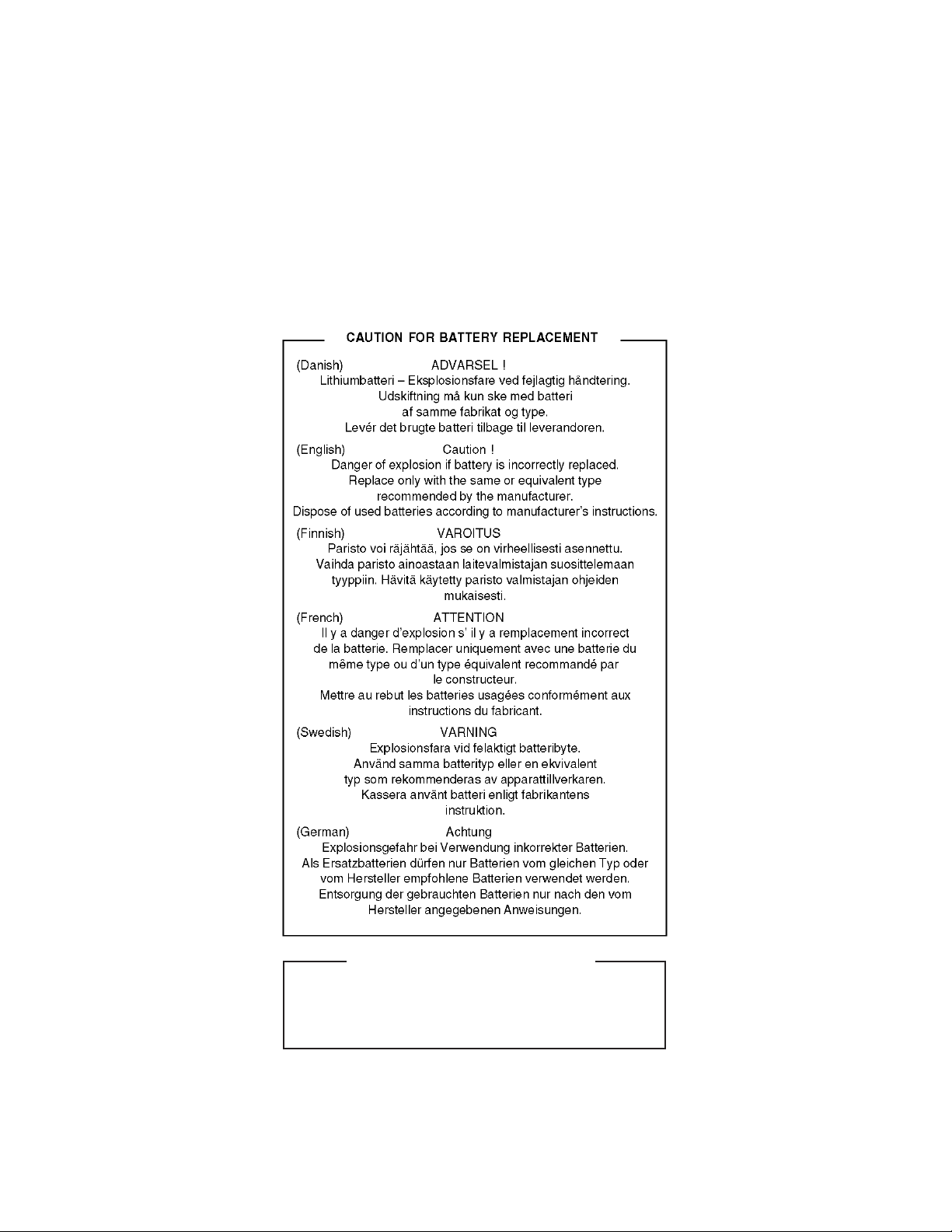
CAUTION FOR BATTERY DISPOSAL
Contains lithium-ion battery. Must be disposed of properly.
Remove the battery from the product and contact
agencies for information on recycling and disposal options.
federal or state environmental
Page 36

cc
COPYRIGHT 2002 BY SHARP CORPORATION
No part of this publication may be reproduced,
electronic, mechanical, photocopying, recording, or otherwise,
without prior written permission of the publisher.
Trademark acknowledgments
Windows and Windows NT are trademarks of Microsoft Corporation in the U.S.A.
and other countries.
IBM and PC/AT are trademarks of International Business Machines Corporation.
PCL is a trademark of Hewlett-Packard Company.
Pentium is a registered trademark of Intel Corporation.
All other trademarks and copyrights are the property of their respective owners.
c
All rights reserved.
Printed in Japan.
stored in a retrieval system, or transmitted,
in any form or by any means,
SHARP CORPORATION
Digital Document System Group
Products Quality Assurance Department
Yamatokoriyama, Nara 639-1186, Japan
2002 July Printed in Japan
 Loading...