

Sharp AL-1045,AL-1555,AL-1255,AL-1456 Operation Manual
AL-1045
AL-1255
AL-1456
AL-1555
DIGITAL MULTIFUNCTIONAL SYSTEM
OPERATION MANUAL
CAUTION
VORSICHT
ADVARSEL
ADVERSEL
VARNING
VARO!
INVISIBLE LASER RADIATION WHEN OPEN AND INTERLOCKS DEFEATED.
AVOID EXPOSURE TO BEAM.
UNSICHTBARE LASERSTRAHLUNG WENN ABDECKUNG GEÖFFNET UND
SICHERHEITSVERRIEGELUNG ÜBERERÜCKT. NICHT DEM STRAHL AUSSETZEN.
USYNLIG LASERSTRÅLING VED ÅBNING, NÅR SIKKERHEDSAFBRYDERE ER
UDE AF FUNKTION. UNDGA UDSAETTELSE FOR STRÅLING.
USYNLIG LASERSTRÅLING NÅR DEKSEL ÅPNES OG SIKKERHEDSLÅS BRYTES.
UNNGÅ EKSPONERING FOR STRÅLEN.
OSYNLIG LASERSTRÅLNING NÄR DENNA DEL ÄR ÖPPNAD OCH SPÄRRAR ÄR
URKOPPLADE. STRÅLEN ÄR FARLIG. BETRAKTA EJ STRÅLEN.
AVATTAESSA JA SUOJALUKITUS OHITETTAESSA OLET ALTTIINA NÄKYMÄTÖNTÄ
LASERSÄTEILYLLE. ÄLÄ KATSO SÄTEESEEN.
Laserstrahl
CLASS 1 LASER PRODUCT
LASER KLASSE 1
LUKOAN 1 LASERLAITE
KLASS 1 LASERAPPARAT
VAROITUS!
LAITTEEN KÄYTTÄMINEN
MUULLA KUIN TÄSSÄ
KÄYTTÖOHJEESSA MAINITULLA
TAVALLA SAATTAA ALTISTAA
KÄYTTÄJÄN
TURVALLISUUSLUOKAN 1
YLITTÄVÄLLE
NÄKYMÄTTÖMÄLLE
LASERSÄTEILYLLE.
VARNING
OM APP ARATEN ANVÄNDS PÅ
ANNAT SÄTT ÄN I DENNA
BRUKSANVISNING
SPECIFICERATS, KAN
ANVÄNDAREN UTSÄTTAS FÖR
OSYNLIG LASERSTRÅLNING,
SOM ÖVERSKRIDER GRÄNSEN
FÖR LASERKLASS 1.
CLASS 1
LASER PRODUCT
LASER KLASSE 1
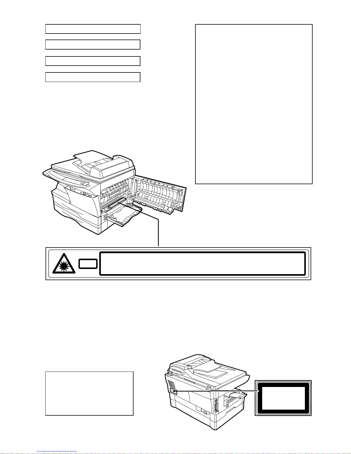
Caution
This product contains a low power laser
device. To ensure continued safety do not
remove any cover or attempt to gain access
to the inside of the product. Refer all
servicing to qualified personnel.

1
CAUTIONS
Cautions on using
Follow the cautions below when using this unit.
Warning:
• The fusing area is hot. Exercise care in this area when removing misfed paper.
• Do not look directly at the light source. Doing so may damage your eyes.
• Do not switch the unit rapidly on and off. After turning the unit off, wait 10 to 15
seconds before turning it back on.
• Unit power must be turned off before installing any supplies.
Caution:
• Place the unit on a firm, level surface.
• Do not install the unit in a humid or dusty location.
• When the unit is not used for a long time, for example for consecutive holidays,
turn the power switch off and remove the power cord from the outlet.
• When moving the unit, be sure to turn the power switch off and remove the power
cord from the outlet.
• Do not cover the unit with a dust cover, cloth or plastic film while the power is on.
Doing so may prevent heat radiation, damaging the unit.
• Use of controls or adjustments or performance of procedures other than those
specified herein may result in hazardous radiation exposure.
• The socket-outlet shall be installed near the equipment and shall be easily
accessible.
Important points when selecting an installation site
Do not install your unit in areas that are:
• damp, humid, or very dusty
• exposed to direct sunlight
• poorly ventilated
• subject to extreme temperature or humidity changes, e.g., near an air conditioner
or heater.
Be sure to allow the required space around the machine
for servicing and proper ventilation.
A small amount of ozone is produced within the unit during opera tion. The emission
level is insufficient to cause any health hazard.
Note:
The present recommended long term exposure limit for ozone is 0.1ppm (0.2mg/m3)
calculated as an 8hr. time-weighted average concentration.
However, since the small amount that is emitted may have an o bjectionable odor, it
is advisable to place the unit in a ventilated area.
20 cm
10 cm
10 cm
2
Cautions on handling
Be careful in handling the unit as follows to maintain the performance of this unit.
Do not drop the unit, subject it to shock or strike it against any object.
Do not expose the drum cartridge to direct sunlight.
• Doing so will damage the surface (green portion) of the drum cartridge, causing
smudges on copies.
Store spare supplies such as drum cartridges and TD cartridges in a dark
place without removing from the package before use.
• If they are exposed to direct sunlight, smudges on copies may result.
Do not touch the surface (green portion) of the drum cartridge.
• Doing so will damage the surface of the cartridge, causing smudges on copies.
Trademark acknowledgements
• Microsoft and Windows are trademarks of Microsoft Corporation in the U.S.A. and
other countries.
• IBM and PC/AT are trademarks of International Business Machines Corporation.
• Adobe and Acrobat are trademarks of Adobe Systems Incorporated.
• All other trademarks and copyrights are the property of their respective owners.
Cautions on laser
In some areas, the "POWER" switch positions are ma rked "I" and "O" on the co pier
instead of "ON" and "OFF".
The symbol "O" denotes the copier is not completely de-energized but in a stand-by
condition at this "POWER" switch position.
If your copier is so marked, please read "I" for "ON" and "O" for "OFF".
Caution!
For a complete electrical disconnection, pull out the main plug.
The socket-outlet shall be installed near the equipment and shall be easily
accessible.
As an ENERGY STAR
®
Partner, SHARP has determined that
this product meets the ENERGY STAR
®
guidelines for energy
efficiency.
Safety precautions:
This Digital Copier is rated Class 1 and complies with 21 CFR 1040.10 and 1040.11 of the
CDRH standards. This means that the unit does not produce hazardous laser radiation. For
your safety, observe the precautions below.
• Do not remove the cabinet, operation panel or any other covers.
• The unit’s exterior covers contain several safety interlock switches. Do not bypass any
safety interlock by inserting wedges or other items into switch slots.
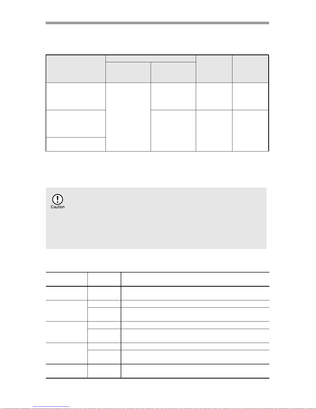
770 nm - 795 nm
11.82 µs/7 mm
0.17 mW 0.01 mW
+
-
Wave length
Pulse times
Output power

3
1
2
4
3
5
6
8
7
9
1 INTRODUCTION
USING THE MANUALS.................4
PART NAMES ...............................5
OPERATION PANEL.....................6
2 SETTING UP THE UNIT
SETUP PROCEDURE...................7
CHECKING PACKED
COMPONENTS AND
ACCESSORIES.............................8
PREPARING THE UNIT FOR
INSTALLATION.............................8
INSTALLING THE
TD CARTRIDGE..........................10
POWER ON............................ ... ..12
3 LOADING PAPER
PAPER.........................................14
LOADING THE PAPER TRAY.....15
BYPASS FEED
(including special paper)..............17
4
INSTALLING THE SOFTWARE
SOFTWARE FOR THE
SHARP PERSONAL MFP
SERIES........................................19
HARDWARE AND SOFTWARE
REQUIREMENTS........................19
BEFORE INSTALLATION ...........20
INSTALLING THE SOFTWARE..21
INDICATORS ON THE OPERATION
PANEL.........................................31
USING THE PRINTER MODE.....32
USING THE SCANNER MODE........ 34
HOW TO USE THE
ONLINE MANUAL .......................42
USING OTHER INSTALLED
DRIVERS.....................................44
CONNECTING THE INTERFACE
CABLE.........................................45
5 MAKING COPIES
COPY FLOW ...............................46
ORIGINAL PLACEMENT.............47
SET THE COPY QUANTITY .......49
EXPOSURE ADJUSTMENT/
PHOTO COPYING.......................49
REDUCTION/ENLARGEMENT/
ZOOM..........................................51
6 SPECIAL FUNCTIONS
ABOUT THE SPECIAL
FUNCTIONS OF
THE AL-1555 ...............................52
DESCRIPTION OF SPECIAL
FUNCTIONS................................54
TONER SAVE MODE..................54
USER PROGRAMS.....................55
DISPLAYING TOTAL NUMBER
OF COPIES .................................56
7 MAINTENANCE
TD CARTRIDGE
REPLACEMENT..........................57
DRUM CARTRIDGE
REPLACEMENT..........................58
CLEANING THE UNIT.................59
8
TROUBLESHOOTING THE UNIT
TROUBLESHOOTING.................61
STATUS INDICATORS................62
MISFEED REMOVAL ..................63
9 APPENDIX
SPECIFICATIONS.......................68
ABOUT SUPPLIES AND
OPTIONS.....................................70
MOVING AND STORING
THE UNIT ....................................71
INDEX..........................................72
SOFTWARE LICENSE................75
CONTENTS

4
This chapter provides basic information fo r usi ng the unit.
USING THE MANUALS
In addition to this printed manual an online manual is also provided. To get full use of all
features and functions of this product, be sure to familiarize yourself with both manuals.
This printed manual provides all installation and setup instructions as well as instructions
in the use of all copier functions. The online manual contains the following information.
Online manual
Provides you with information on how to specify preferences and troubleshooting. Check
the online manual when you use this unit after all the initial setup is completed.
How to use the online manual
Explains how to use the online manual.
Print
Provides information on how to print a document.
Scan
Explains how to scan using the scanner driver and how to adjust the settings for
the Button Manager.
Troubleshooting
Provides instructions on how to solve driver or software problems.
Conventions used in this manual and online manual
• This operation manual explains the operation of the AL-1 045, AL-1255, A L-1456, and
AL-1555 models. In cases where the operation is the same, the AL-1555 is used.
• Illustrations of driver screens and other computer screens show the screens that
appear in Windows XP Home Edition. Some of the names that appear in these
illustrations may differ slightly from the screens that appear in other operating systems.
• This operation manual refers to the Single Pass Feeder as the "SPF", and the
Reverse Single Pass Feeder as the "RSPF".
• In this manual, the following icons are used to provide the user with information
pertinent to the use of the unit.
Warns the user that injury may result if the contents of the warning
are not properly followed.
Cautions the user that damage to the unit or one of its components
may result if the contents of the caution are not properly followed.
Notes provide information relevant to the unit regarding
specifications, functions, performance, operation and such, that
may be useful to the user.
Indicates a letter displayed in the display.
1
INTRODUCTION
5
1
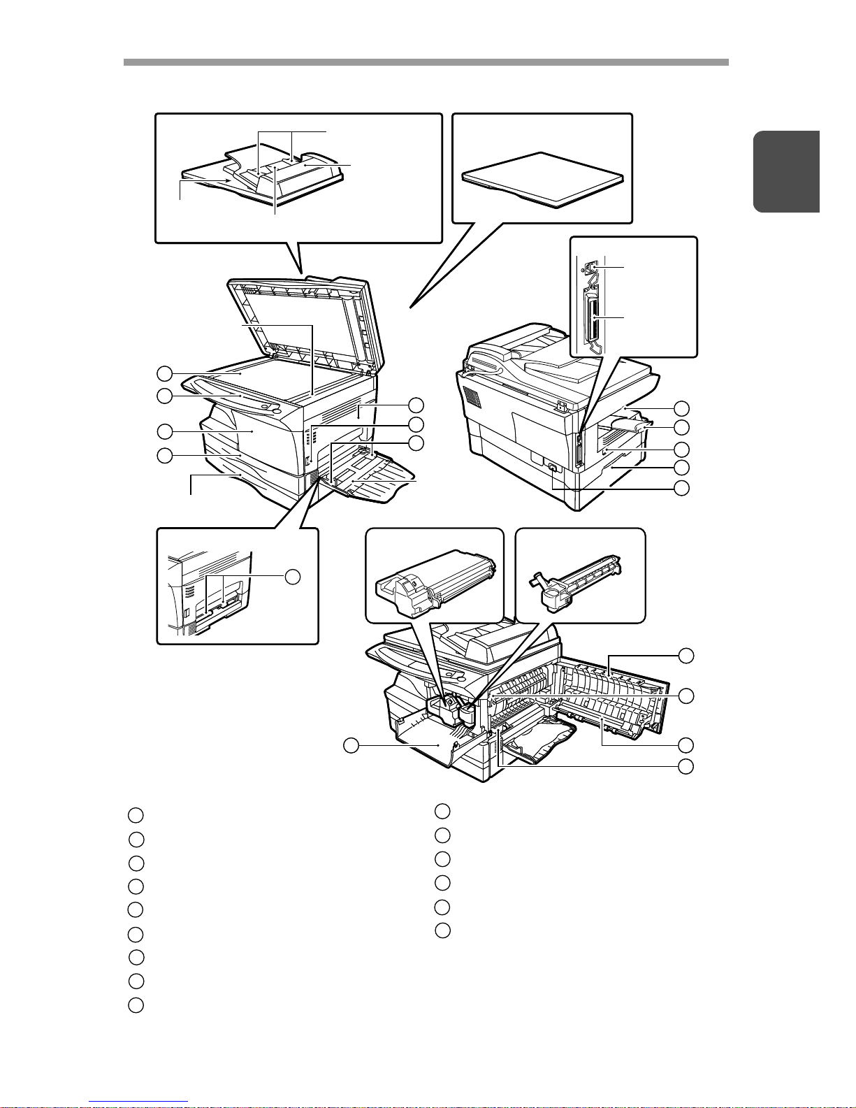
PART NAMES
Interface
TD cartridge Drum cartridge
SPF/RSPF Original cover
Original
exit area
2
3
4
1
5
7
6
8
9
10
11
13
14
15
7
Single bypass
USB
interface
Parallel
interface
Multi-bypass
tray
Paper tray 2
SPF/RSPF
scan area
Original guide
Original feeder tray
Feeding
roller cover
5
3
12
Interface
TD cartridge Drum cartridge
SPF/RSPF Original cover
Original
exit area
2
3
4
1
5
7
6
8
9
10
11
13
14
15
7
Single bypass
USB
interface
Parallel
interface
Multi-bypass
tray
Paper tray 2
SPF/RSPF
scan area
Original guide
Original feeder tray
Feeding
roller cover
5
3
12
Original table
Operation panel
Front cover
Paper tray
Side cover
Side cover open button
Bypass paper guides
Paper output tray
Paper output tray extension
1
2
3
4
5
6
7
8
9
Power switch
Handle
Power cord socket
Fusing unit release lever
Transfer charger
Charger cleaner
10
11
12
13
14
15
6
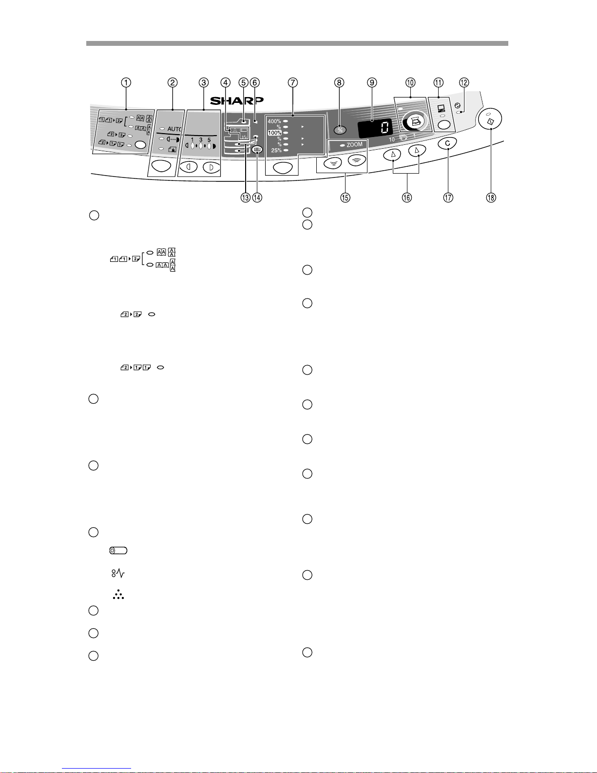
OPERATION PANEL
AL-1555
A5
A4
A4
B5
A4
A5
141
86
70
Original to copy key and indicators
(AL-1555)
Two-sided copies from
one-sided originals.
Turn on Long Edge or
Turn on Short Edge
can be selected.
Two-sided copies from
two-sided originals. (Can
be selected only when
the RSPF is used.)
Single-sided copies
from two-sided
originals. (Can be
selected only when the
RSPF is used.)
Exposure mode selector key and
indicators
Use to sequentially select the exposure
modes: AUTO, MANUAL or PHOTO.
Selected mode is shown by a lit
indicator. (p.49)
Light and dark keys and exposure
indicators
Use to adjust the MANUAL or PHOTO
exposure level. Selected exposure level is
shown by a lit indicator. (p.49) Use to start
and terminate user program setting. (p.55)
Alarm indicators
Drum replacement required
indicator (p.58)
Misfeed indicator (p.63)
TD cartridge replacement
required indicator (p.57)
SPF/RSPF indicator (p.48)
(AL-1255/AL-1456/AL-1555)
SPF/RSPF misfeed indicator (p.66)
(AL-1255/AL-1456/AL-1555)
Copy ratio selector key and
indicators
Use to sequentially select preset
reduction/enlargement copy ratios.
Selected copy ratio is shown by a lit
indicator. (p.51)
1
2
3
4
5
6
7
Copy ratio display (% ) key (p.51)
Display
Displays the specified copy quantity,
zoom copy ratio, user program code,
and error code.
SCANNER key and indicator
(p.31, p.38)
(AL-1255/AL-1456/AL-1555)
ON LINE key and indicator
Lights up when the unit is used as a
printer and scanner. For description of
the ON LINE indicator, see
"INDICATORS ON THE OPERATION
PANEL" (p.31).
Power save indicator
Lights up when the unit is in a power
save mode. (p.54, p.55)
Paper feed location indicators
Light up to show the selected paper
feed station.
Tray select key (AL-1456/AL-1555)
Use to select a paper feed station
(paper tray or multi-bypass tray). (p.53)
Zoom keys and indicator
Use to select any reduction or
enlargement copy ratio from 25% to
400% in 1% increments. (p.51)
Copy quantity keys
• Use to select the desired copy
quantity (1 to 99). (p.49)
• Use to make user program entries.
(p.55)
Clear key
• Press to clear the display, or press
during a copy run to terminate
copying. (p.49)
• Press and hold down during standby
to display the total number of copies
made to date. (p.56)
Start key and indicator
• Copying is possible when the
indicator is on.
• Press to start copying
• Use to set a user program. (p.55)
8
9
10
11
12
13
14
15
16
17
18
7
2
Follow the installation procedure below to use the unit properly.
SETUP PROCEDURE
When using the unit for the first time, setup the unit following the procedure shown
below.
*
1
If you are only using the unit for copying, skip this step.
*
2
The multi-bypass tray is only included with the AL-1555.
If the unit does not function properly during setup or use, or if a function
cannot be used, see "TROUBLESHOOTING THE UNIT" (p.61).
1 Open the package, and make sure that all the accessories are
supplied with the unit. (p.8)
2 Remove the protective materials. (p.9)
8 Now, you can copy (p.46), print (p.32), or scan (p.34) your
document.
3 Install the TD cartridge. (p.10)
4 Load the paper in the paper tray (p.15) or the multi-bypass
tray*
2
. (p.17)
5 Plug the other end of the power cord into the nearest outlet. (p.12)
6 Install the software.*1 (p.19)
7 Connect the interface cable*1 (p.45) and turn on the unit. (p.12)
2
SETTING UP THE UNIT
8
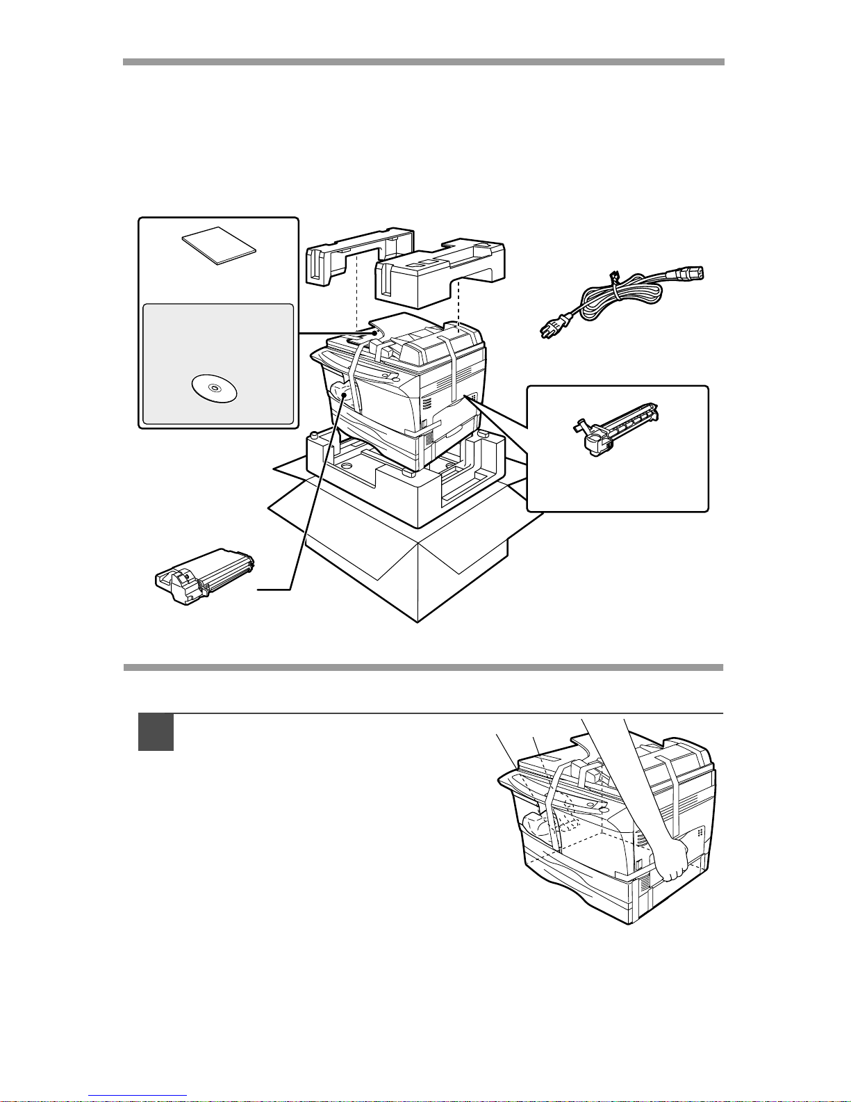
CHECKING PACKED COMPONENTS AND
ACCESSORIES
Open the carton and check if the following components and accessories are
included.
If anything is not included or is damaged, contact your authorized Service
representative.
PREPARING THE UNIT FOR INSTALLATION
1
Be sure to hold the handles on
both sides of the unit to unpack
the unit and carry it to the
installation location.
Drum cartridge
(installed in unit)
Operation manual
AL-1045
AL-1255
AL-1456
AL-1555
Software CD-ROM
TD cartridge
9
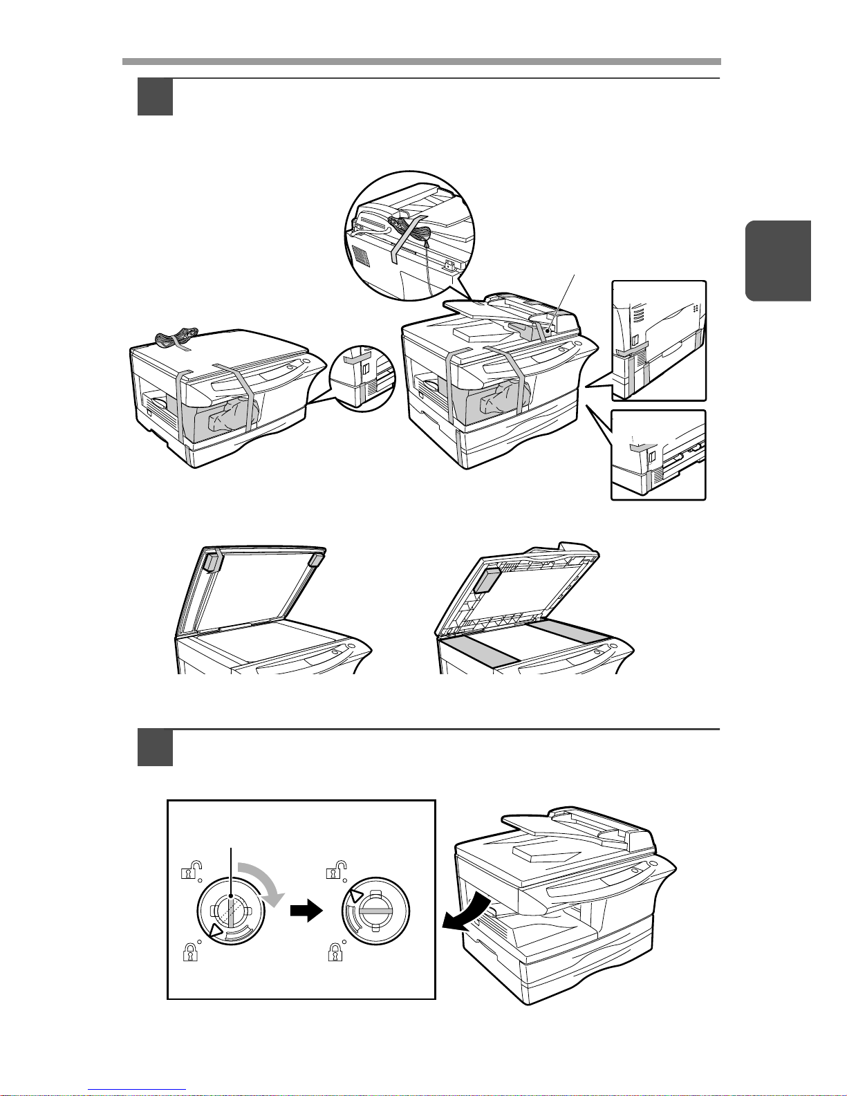
2
2
Remove all pieces of tape shown in the illustration belo w. Then
open the original cover/SPF/RSPF and remove protective
materials. After that, take out the bag containing the power
cord and TD cartridge.
3
Release the scan head locking switch.
The scan head locking switch is under the original table.
AL-1555
AL-1255
AL-1456
(AL-1555 only)
AL-1045
AL-1045
AL-1255/AL-1456/AL-1555
AL-1255/AL-1456/AL-1555
Lock Unlock
Grasp here and turn in
the direction of the arrow.
10
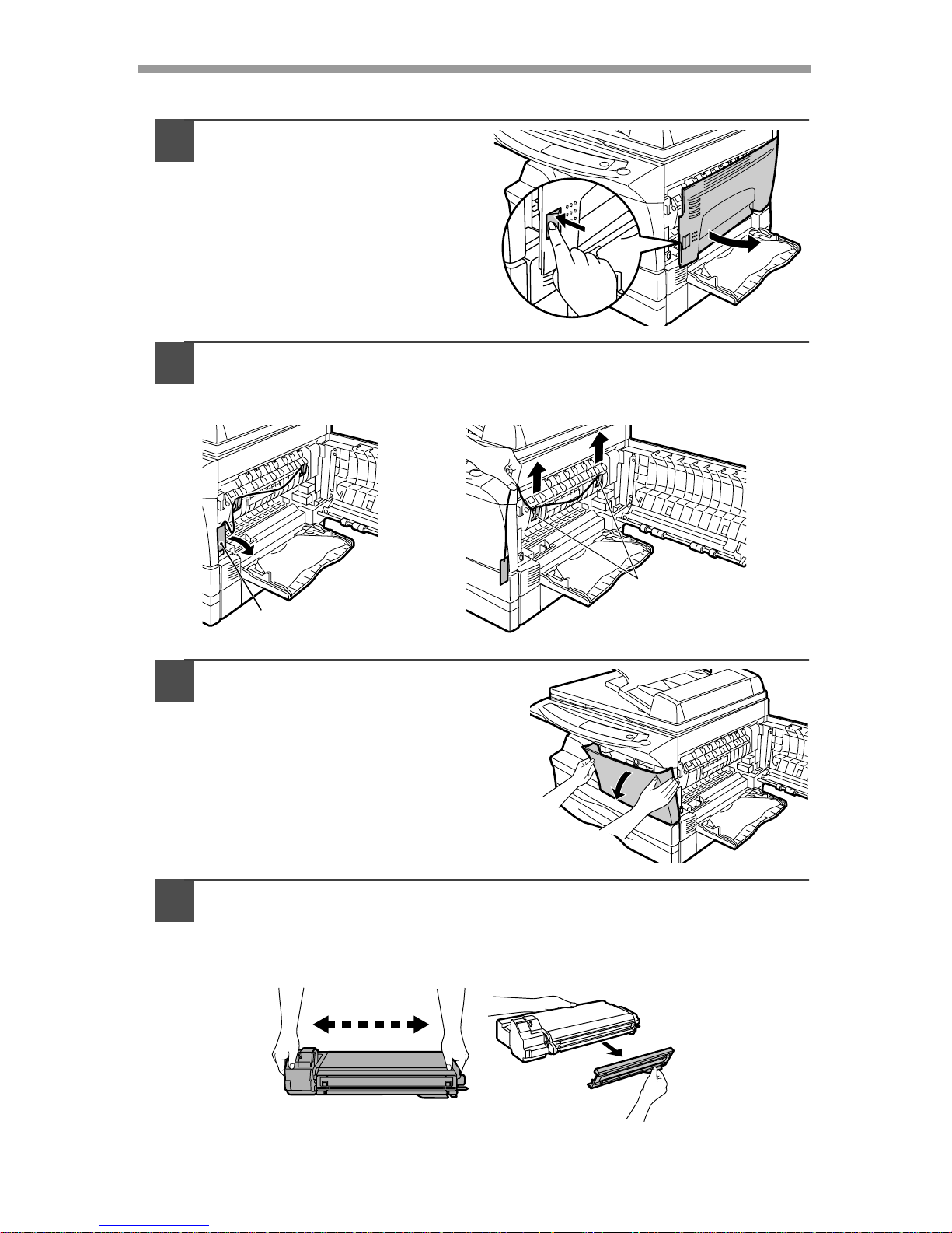
INSTALLING THE TD CARTRIDGE
1
Open the multi-bypass tray
(AL-1555, p.17), and then
open the side cover.
2
Remove the CAUTION tape from the front cover and remove the
two protective pins from the fusing unit by pulling the strings
upward one at a time.
3
Push gently on both sides of the
front cover to open the cover.
4
Remove the TD cartridge from the bag. Remove the protective
paper. Hold the cartridge on both sides and shake it
horizontally four or five times. Hold the tab of the protective
cover and pull the tab to your side to remov e the cover.
CAUTION tape
Protective pins
4 or 5 times
11
2
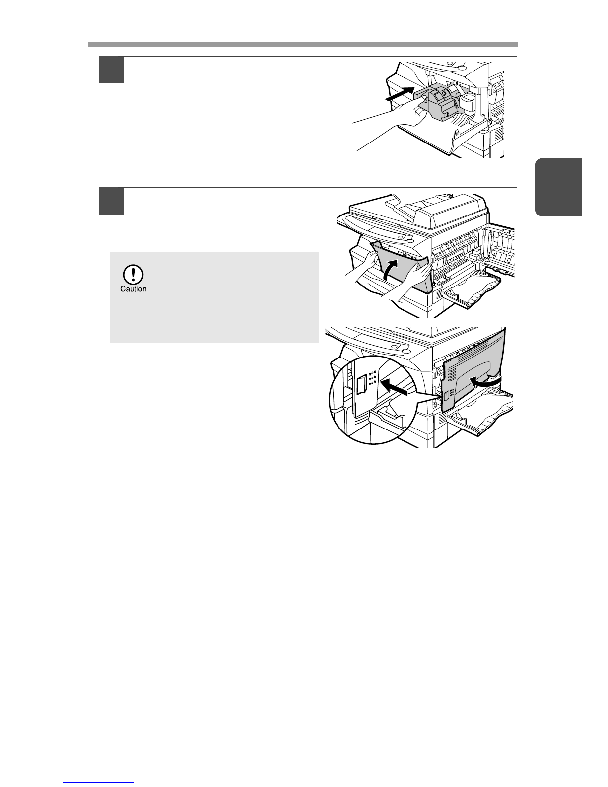
5
Gently insert the TD cartridge
until it locks in place while
pushing the lock release button.
6
Close the front cover and the n
the side cover by pressing the
round projections near the
side cover open button.
When closing the covers, be
sure to close the front cover
securely and then close the
side cover. If the covers are
closed in the wrong order, the
covers may be damaged.

12
POWER ON
Ensure that the power switch of the unit is in the OFF posi tion. Insert the attached
power cord into the power cord socket at the rear of the unit. Plug the other end of
the power cord into the nearest outlet. Turn the power switch on the left side of the
unit to the "ON" position. The start ( ) indicator will light up and other indicators
which show the initial settings of the operation panel will also light up to indicate the
ready condition. For the initial settings, see the "Initial settings of operation pa nel"
described on the next page.
About the scan head
The scan head lamp remains on constantly when the unit is in the ready condition
(when the Start indicator is illuminated).
The unit adjusts the scan head lam p pe ri o di cally to maintain copying quality. At this
time, the scan head moves automatically. This is normal and does not indicate unit
trouble.
If you use the unit in a country other than the country where the unit was
purchased, you will need to make sure that your local power supply is
compatible with your model. If you plug the unit into an incompatible
power supply, irreparable damage to the unit will result.
Only insert the power cord into a properly grounded wall socket.
Do not use extension cords or power strips.
• The unit will enter a power save mode once the set time has elapsed
without any unit operation . The settings of the power save modes can
be modified. See "USER PROGRAMS" (p.55).
• The unit will return to the initial settings a preset amount of time after
the end of copy, or scanner job. The preset amount of time (auto clear
time) can be changed. See "USER PROGRAMS" (p.55).
13
2
Initial settings of operation panel
When the unit power is on, the operation panel will revert to the initial settings when
the time set with the "Auto clear time" setting (p.54) elapses after a copy or scanner
job is finished, or when the clear ( ) key is pressed twice.
The initial settings of the operation panel are shown below.
When copying is begun in this state, the settings in the following table are used.
Power off methods
If not used for a certain period of time, the unit will automatically enter auto power
shut-off mode (p.54) in order to minimize power consumption. In cases where the
machine will not be used for a long time, turn off the power switch and remove the
power cord from the outlet.
Copy quantity 1 copy
Exposure adjustment Auto
Zoom 100%
AL-1555 only
Original to copy The "Original to copy" indicator does
not illuminate. (One-sided copying
only)
Tray Paper tray 1
AL-1555
A5
A4
A4
B5
A4
A5
141
86
70
"0" is displayed in the displ ay .

14
Follow the steps below to load paper into the tray.
PAPER
For best results, use only paper recommended by SHARP.
* Do not use non-standard envelopes, and envelopes that have metal clasps, plastic
snappers, string closures, windows, linings, self-adhesive, patches or synthetic
materials. Do not use envelopes that are filled with air or envelopes that have
labels or stamps attached. These will cause physical damage to the unit.
**For paper weighing from 104 to 128g/m
2
, A4 is the maximum size that can be fed
through the single bypass or the multi-bypass tray.
• Special papers such as transparency film, labels and envelope must be fed one
sheet at a time through the single bypass or the multi-bypass tray.
Type of paper
feeding
Type of media Size Weight
Paper tray Standard paper A4
B5
A5
Letter
Legal
Invoice
56 to 80g/m
2
Single bypass/
Multi-bypass
tray
Standard paper and
thick paper
A4
B5
A5
B6
A6
Letter
Legal
Invoice
52 to 128g/m
2
**
Special
media
Transparency
film
A4
Letter
Envelope* International DL
International C5
Commercial 10
Monarch
3
LOADING PAPER
15
3
LOADING THE PAPER TRAY
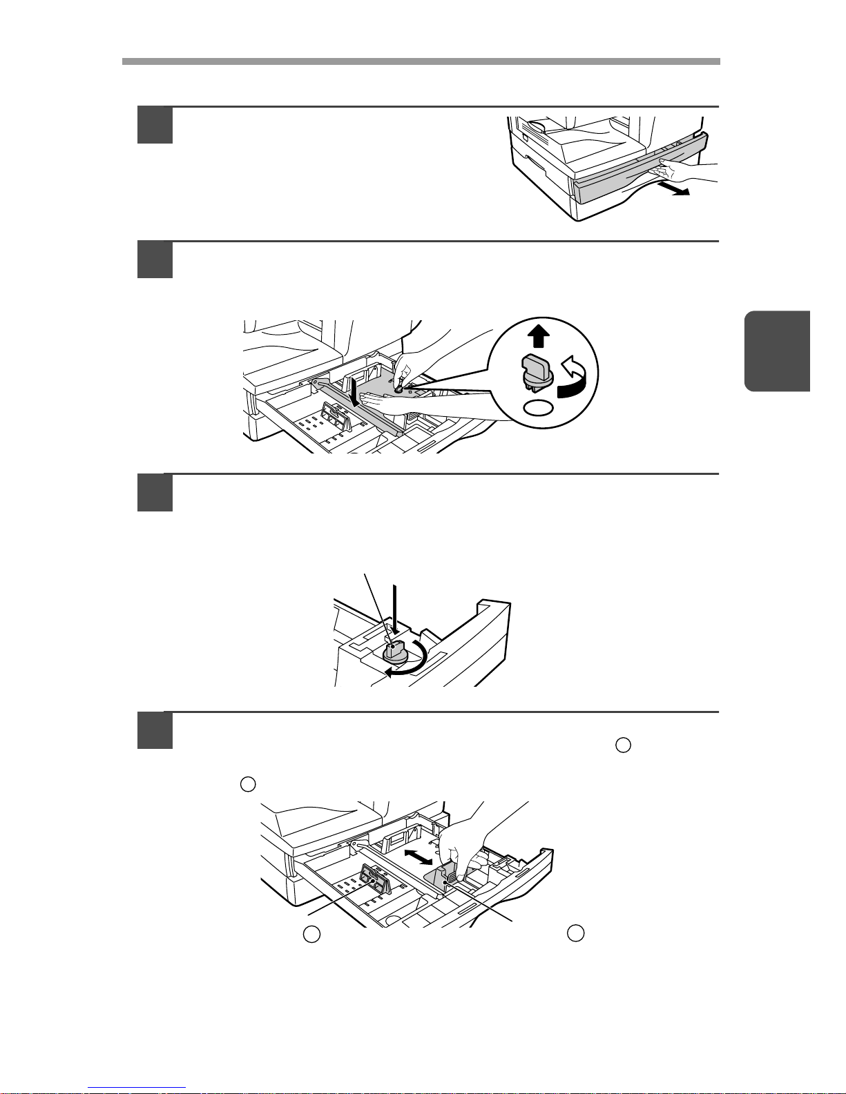
1
Raise the handle of the paper tray
and pull the paper tray out until it
stops.
2
Remove the pressure plate lock. Rot ate th e pressur e plate lock
in the direction of the arrow to remove it while pressing down
the pressure plate of the paper tr ay .
3
Store the pressure plate lock which has been removed in step 2.
To store the pressure plate lock, rotate the lock to fix it on the
relevant location.
4
Adjust the paper guides on the paper tray to the copy paper
width and length. Squeeze the lev er of paper guide and slide
the guide to match with the width of the paper. Move paper
guide to the appropriate slot as marked on the tray.
Pressure plate lock
A
B
Paper
guide B
Paper
guide A
16
5
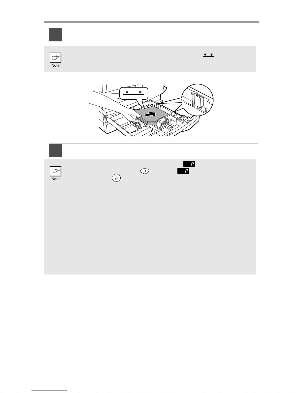
Fan the paper and insert it into th e tray. Make sure the edge s go
under the corner hooks.
6
Gently push the paper tray back into the unit.
Do not load paper above the maximum height line ( ). Exceeding
the line will cause a paper misfeed.
• After loading paper, to cancel the blinking without restarting
copying, press the clear ( ) key. The in the display will go out
and the start ( ) indicator will light up.
•
Be sure that paper is free of rips, dust, wrinkles, and curled or bent edges.
• Make sure all the paper in the stack is the same size and type.
• When loading paper, ensure there is no space between the paper and
the guide, and check if the guide is not set too narrow causing the
paper to bend. Loading paper in these ways will result in document
skew or a paper jam.
• When not using the unit for an extended period, remove all paper from
the paper tray and store it in a dry place. If paper is left in the unit for
an extended period, the paper will absorb moisture from the air,
resulting in paper jams.
•
When adding new paper to the paper tray, remove the old paper already
contained in the tray. Placing new paper on top of the paper already
contained in the tray may result in feeding two sheets at one time.
17
3
BYPASS FEED (including special paper)
The multi-bypass tray (AL-1555) or the single bypass (AL-1045/AL-1255/AL-1456) can be used
to feed standard paper, transparency film, labels, envelopes, and other special purpose paper.
Paper measuring from A6 to A4 and in the weight range of 52 to 128g/m
2
can be used in this
tray. (For paper weighing from 104 to 128g/m
2
, A4 is the maximum size.)
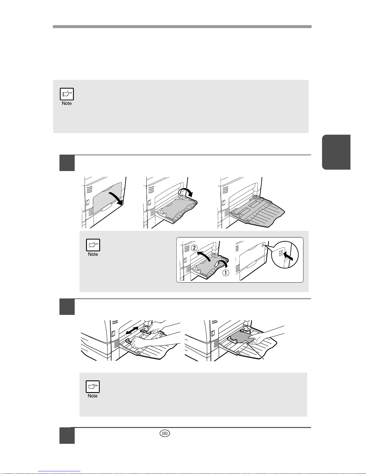
The multi-bypass tray (AL-1555)
1
Open the multi-bypass tray and ext end the tray.
2
Set the paper guides to the paper width. Insert the paper (print
face down) all the way into the multi-bypass tray.
3
Press the tray select ( ) key to select the multi-bypass tray.
•
The multi-bypass tray (AL-1555) can hold maximum of 50 sheets of
paper. (Capacity will vary depending on the type of paper loaded.) The
single bypass (AL-1045/AL-1255/AL-1456) can hold one sheet of paper.
• The original image must be smaller than the paper or media for
copying. If the original image is bigger than the paper or media, this
may cause smudges on the edges of the copies.
To close the multibypass tray, perform
step 1 and then step 2 in
the illustration and push
the round projections at
the right of the tray until
they click.
•
Paper must be fed narrow side into the feed slot.
•
Transparency film, labels, and other special purpose papers must
be fed individually.
•
When copying onto transparency film, remove each copy promptly. Do not let
copies stack up. When loading an envelope, make sure that it is straight and flat.
Print face
18
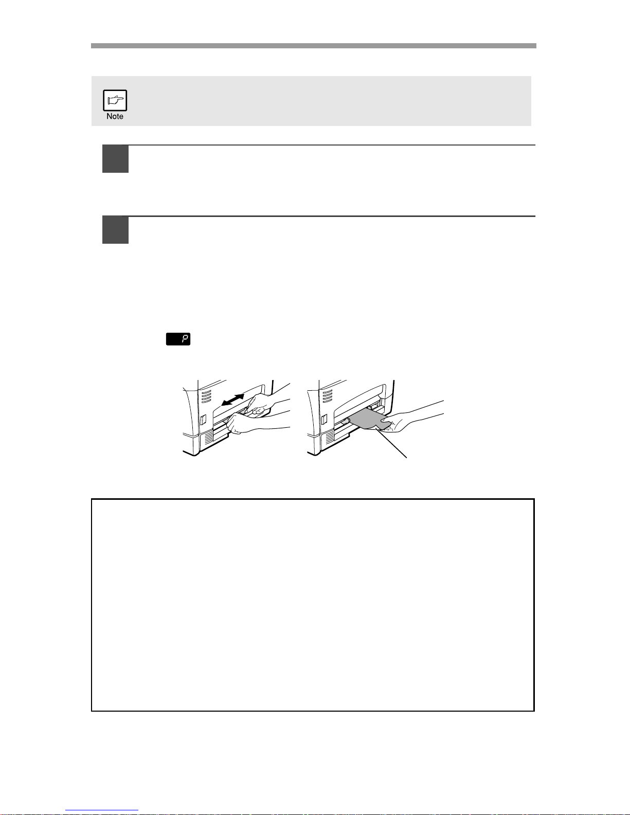
The single bypass (AL-1045/AL-1255/AL-1456)
1
Select copy and print settings before you begin the copy job.
For information on the copy settings, see "MAKING COPIES" (p.46)". For
information on the print settings, see the online manual or the Help file for
the printer driver, and then begin printing from the single bypass.
2
Set the paper guides to the paper width. In sert a single sh eet of
copy or print paper (print face down) into the feed slot of the
single bypass.
Using copy mode
When you insert the paper, the machine will automatically draw in the paper
and begin copying.
Using printer mode
After appears in the display, wait until the Paper feed location indicator
for the single bypass illuminates and insert the paper. The machine will
automatically draw in the paper and begin printing.
If you insert a sheet of paper into the single bypass when multiple copies
have been set with the copy quantity setting (p.49), the copy quantity
setting will change to "0" and only one copy will be made.
Note for loading envelopes
• Envelopes must be fed narrow side into the feed slot one sheet at a time.
• Do not use non-standard envelopes, and envelopes that have metal clasps,
plastic snappers, string closures, windows, linings, self-adhesive, patches or
synthetic materials. Do not use envelopes that are filled with air or envelopes that
have labels or stamps attached.
• Envelopes of which the surface is not flat because of embossing may cause the
prints to become smudged.
• Under high humidity and temperature conditions the glue flaps on some
envelopes may become sticky and be sealed closed when printed.
• Use only envelopes which are flat and crisply folded. Curled or poorly formed
envelopes may be poorly printed or may cause misfeeds.
• Be sure to select either Com10, DL, C5 or Monarch on the paper size setting of
the printer driver. (For detailed information on printer driver, refer to the online
manual.)
• It is recommended that you perform a test print before performing the actual print
job.
Print face
19
4
This chapter provides you with information on how to install required software to use
this unit with your computer. Information on how to use the online manual is also
provided. The following term is used in this chapter.
CD-ROM
Means the supplied CD-ROM with the SHARP Personal MFP Series software.
SOFTWARE FOR THE SHARP PERSONAL MFP SERIES
The supplied CD-ROM includes software for this unit.
MFP driver
Scanner driver
Permits you to operate scanning function of this unit with TWAIN-compliant and
WIA-compliant application.
Printer driver
Enables you to use the printer function of this unit with your computer.
Print Status Window
The print state and information on current printing are displayed on the sta tus
monitor window.
Sharpdesk
An integrated software environment that makes it easy to manage document and
image files and launch applications.
Button Manager
Button Manager enabling the SCANNER ( ) key located on the unit.
HARDWARE AND SOFTWARE REQUIREMENTS
Check the following hardware and software requirements in order to install the software.
*1Compatible with Windows 98, Windows Me, Windows 2000 Professional , Windows XP
Professional or Windows XP Home Edition preinstalled model with USB interface
equipped as standard.
*
2
Printing is unavailable in MS-DOS mode.
*
3
The administrator's authorization is required to install this software using this installer.
Computer type IBM PC/AT or compatible computer equipped with a
USB1.1*
1
or bi-directional parallel interface (IEEE 1284)
Operating system*
2
Windows 95, Windows 98, Windows Me, Windows NT
Workstation 4.0 (ServicePack 5 or later)*
3
, Windows 2000
Professional, Windows XP Professional*
3
, Windows XP
Home Edition*
3
Display 800 x 600dots (SVGA) display with 256 colors (or better)
Hard disk free space
150MB or more
Other requirement
for hardware
An environment on which any of the operating systems listed
above can fully operate
4
INSTALLING THE SOFTWARE
20
BEFORE INSTALLATION
The following table shows the drivers and software that can be installed for each
version of Windows and interface connection method.
*1When the unit is connected through the parallel port, the Print Status Window can only
be used when the parallel port is set to ECP mode. To set the parallel port mode, refer
to your computer manual or ask the manufacturer of your computer.
*
2
Sharpdesk can be installed when using a paralle l interface connection, however, the
unit’s scanner function cannot be used.
Flow of installation
Refer to the following table and then begin installation
MFP Driver
Button
Manager
Sharpdesk
Printer driver/
Print Status
Window
Scanner driver
Users of Windows
98/Me/2000/XP who
will use the USB
interface connection
Available*
1
Available Available Available
Users of Windows
98/Me/2000/XP who
will use the parallel
interface connection
Not Available
Not
Available
Available*
2
Windows 95/NT 4.0
users
•
If you are using some of your computer’s memory as a RAM drive, the
printer driver may not be allocated the correct amount of memory. In such
a case, reduce the size of your RAM disk, or do not use the RAM disk.
Please refer to your Windows documentation for further information.
• Is there another GDI printer driver or a Windows Printing System
printer driver already installed? If installed, change the printer port
setting. For the change of the printer port setting, see "USING OTHER
INSTALLED DRIVERS" (p.44).
Operating
system
Interface Reference pages for how to install
Windows XP
USB/
Parallel
Installing onto Windows XP (USB/parallel interface)
(p.21)
Windows 98
USB
Installing onto Windows 98/Me/2000 (USB interface) (p.25)
Parallel
Installing onto Windows 95/98/Me/NT4.0/2000
(Parallel interface) (p.28)
Windows Me
USB
Installing onto Windows 98/Me/2000 (USB interface) (p.25)
Parallel
Installing onto Windows 95/98/Me/NT4.0/2000
(Parallel interface) (p.28)
Windows 2000
USB
Installing onto Windows 98/Me/2000 (USB interface) (p.25)
Parallel
Installing onto Windows 95/98/Me/NT4.0/2000
(Parallel interface) (p.28)
Windows 95/
NT 4.0
Parallel
Installing onto Windows 95/98/Me/NT4.0/2000
(Parallel interface) (p.28)
21
4
INSTALLING THE SOFTWARE
The following term is used in this section.
MFP
Means the unit as a printer and scanner.
Installing onto Windows XP (USB/parallel interface)
Before starting the installation, make sure the USB or parallel interface cable is not
connected to the MFP.
1
Insert the supplied CD-ROM into your CD-ROM drive.
2
Click the "start" button, click "My Computer" ( ), and then
double-click the CD-ROM ( ) icon.
3
Double-click the "Setup" ( ) icon.
4
Select the software packages to be
installed, and then click the "Next"
button.
The software packages with checkmark ( )
on the list on the screen will be installed.
Click the "Display README" button to show
the information on the selected package.
• For this description, it is assumed that the mouse is configured for
right hand operation.
• To print or scan, the MFP must be in the online state.
• The scanner feature only works when using a USB interface cable.
• If any error message appears, solve the problem following the
instructions on the screen. After your problem is solved, the installing
procedure will be continued. Depending on your problem, you may
have to exit the installer. In this case, click the "Cancel" button to exit
the installer. After solving your problem, reinstall the software from the
beginning.
When any of "Found New Hardware Wizard" messages appear during
the software installation, be sure to click the "Cancel" button.
If the language selection screen appears after you double click the
"Setup" icon, select the language you wish to use and click the "Next"
button. (Normally, the correct language is selected automatically.)
22
5
Review the software packages to be
installed on the screen , an d th e n cl ic k
the "Start" button.
The software packages to be installed will be
displayed on the screen. If inappropriate
packages are displayed, click the "Back" button
to select appropriate packages again.
6
Copying files for MFP driver installation and parallel interface
setup (This step will start if it was selected in step 4).
1
After confirming the message in the "Welcome" window, click the
"Next" button.
2
A dialog box appears asking you to verify that the USB or parallel
interface cable is not connected to the MFP. Make sure that the
interface cable is not connected and click the "Next" button.
3
Click the "Next" button in the dialog box to
install the MFP driver or Cancel to quit the
installation.
The setup program will start to copy the files.
If the following screen appears while the files are
being copied (the message may appear more
than once), click "Continue Anyway".
4
When the "The MFP driver installation is complete." dialog box
appears, click the "OK" button.
The Button Manager installer will start.
• If you are using the parallel interface connection, do not select the
Button Manager checkbox because this feature is not supported with
the parallel interface.
• If the following screen appears, click the "OK" button. Review the
contents in "BEFORE INSTALLATION" (p.20), and then select only
appropriate the software packages to be installed.

23
4
7
Begin installation of the Button Mana ger (This step will start if it
was selected in step 4).
1
After confirming the message in the "Welcome" window, click the
"Next" button.
2
Read the message in the "Please read the following information."
window, and then click the "Next" button.
3
When a message appears that lets you specify the location for the
software to be installed, click the "Next" button.
4
If the program displays "Do you want the Button Manager added to
Windows Startup?", check "Yes" and click the "OK" button.
The setup program will start to copy the files.
5
Click the "Finish" button when the message informs you that
setup is successful.
The Sharpdesk installer will start.
8
Begin installation of the Sharpdesk (This step will start if it was
selected in step 4).
1
After confirming the message in the "Welcome to Sharpdesk
installation" window, click the "Next" button.
2
Read the message in the "Information" window, and then click the
"Next" button.
3
When the "Choose Destination Location" window appears, click
the "Next" button.
4
When the "Select Program Folder" window appears, click the
"Next" button.
5
Click the "Finish" button when the message informs you that
Setup is complete.
9
Click the "Close" button when the
message informs you that "Setup has
finished". When the "Now connect the
MFP interface cable to the PC" dialog
box appears, click the "OK" button.
After the installation, a message to
restart your computer may be
displayed. In this case, click the "Yes"
button to restart your computer.

24
10
Connect the USB interface cable or parallel interface cable.
(p.45)
Windows will detect the MFP and the Plug and Play screen will appear. If
you are using Windows XP with the parallel interface, go to step 12.
11
Begin installation of the scanner driver.
1
"SHARP AL-xxxx" (where xxxx is the model name of your MFP)
will appear in the "Found New Hardware Wizard" dialog box.
Select "Install the software automatically (Recommended)" and
click the "Next" button.
2
The "Install hardware" dialog box will appear. Click the "Continue
Anyway" button.
3
When installation of the driver is completed, click the "Finish"
button to finish the scanner driver installation.
12
Begin installation of the printer driver.
1
"SHARP AL-xxxx" (where xxxx is the model name of your MFP)
will appear in the "Found New Hardware Wizard" dialog box.
Select "Install the software automatically (Recommended)" and
click the "Next" button.
2
The "Hardware Installation" dialog box will appear. Click the
"Continue Anyway" button.
3
When installation of the driver is completed, click the "Finish"
button to finish the printer driver installation.
You have completed the installation of all the softwa re.
25
4
Installing onto Windows 98/Me/2000 (USB interface)
Before starting the installation, make sure the USB interface cable is not connected
to the MFP.
1
Insert the supplied CD-ROM into your CD-ROM drive.
2
Double-click "My Computer" ( ), and then double-click the
CD-ROM ( ) icon.
3
Double-click the "Setup" ( ) icon.
4
Select the software packages to be
installed, and then click the "Next"
button.
The software packages with checkmark ( )
on the list on the screen will be installed. Click
the "Display README" button to show the
information on the selected package.
5
Review the software packages to be installed on the screen,
and then click the "Start" button.
The software packages to be installed will be displayed on the screen. If
inappropriate packages are displayed, click the "Back" button to select
appropriate packages again.
When any of "Hardware Found", or "Found New Hardware Wizard"
messages appear during the software installation, be sure to click the
"Cancel" button.
If the language selection screen appears after you double click the
"Setup" icon, select the language you wish to use and click the "Next"
button. (Normally, the correct language is selected automatically.)
If the following screen appears, click the "OK" button. Review the
contents in "BEFORE INSTALLATION" (p.20), and then select the
appropriate driver software packages to be installed.
 Loading...