

Page 1
SUPPLEMENTAL SER VICE MANU AL
S2204AFR125CX
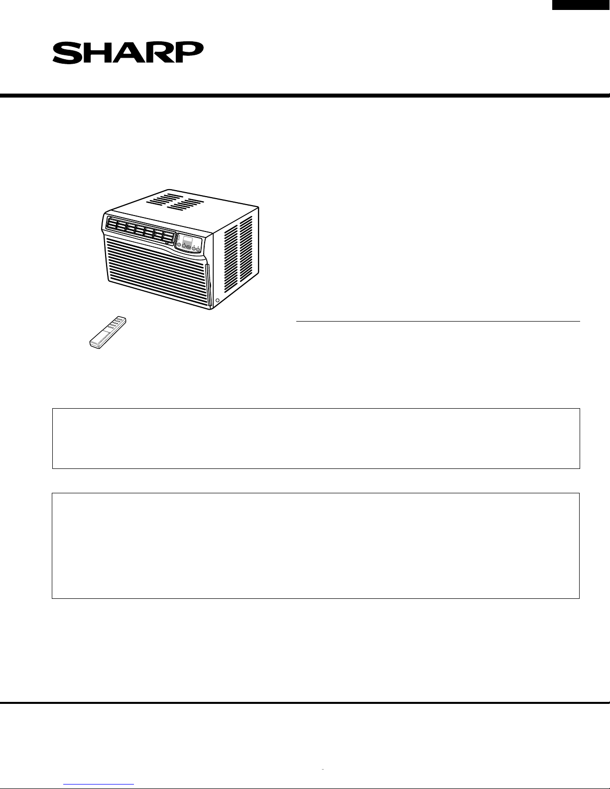
AIR CONDITIONER
AF-R125CX
MODEL
In the interest of user-safety the air conditioner should be restored to
its original condition and only parts identical to those specified should
be used.
This is supplemental Service Manual for Model AF-R125CX.
AF-R125CX are quite similar to base Model AF-R120CX. (Refer No.S2203AFR12CX/).
Use this supplemental manual together with the base Model Service Manual.
Refer to the base Model Servive Manual for complete operation, service information, etc.
TABLE OF CONTENTS
SPECIFICATIONS .................................................................................................................................................2
WIRING DIAGRAM................................................................................................................................................3
EXTERNAL DIMENSIONS .................................................................................................................................... 3
OPERATION INSTRUCTIONS..............................................................................................................................4
REPLACEMENT PARTS LIST ..............................................................................................................................5
AF-R125CX
Page
SHARP CORPORATION This document has been published to be used for after
sales service only.
The contents are subject to change without notice.
1
Page 2
AF-R125CX
SPECIFICATIONS
Models AF-R125CX
Cooling capacity BTU/h 12000
Moisture removal Pints/h 3.3
ELECTRICAL DATA
Phase Single
Rated frequency Hz 60
Rated voltage Volts 115
Rated current Amps 11.5
Rated input Watts 1200
Power factor % 91
EER BTU/Wh 10.0
COMPRESSOR
Type (Hermetically sealed rotary type)
Model, Remarks 44B124HX1EF, 1000 W
REFRIGERANT SYSTEM
Evaporator Slit fin, Grooved tube, ø 9.53 mm Hair pin
Condenser
Control O.D. x I.D. x Length x Q'ty(mm)
Refrigerant volume R-22(OZ) 19.4 (Factory charged)
Louver fin,Grooved tube,7mm Hair pin
Capillary tube 2.7 x 1.2 x 800 x 2
NET DIMENSIONS
Width Height Depth
inches(mm)
22-1/16(560) x 14-3/4(375) x 24-5/16(617)
Net Weight lbs 85
GROSS DIMENSIONS
Width Height Depth
inches(mm)
25-25/32(655) x 18-29/32(480) x 27-7/8(708)
Gross Weight lbs 96
FAN SYSTEM
Indoor side(Evaporator) Centrifugal fan
Outdoor side(Condenser) Propeller fan
Air flow rate(indoor side) CFM (High/Med/Low) 318 / 254 / 219
OTHERS
Safety devices Compressor: Overload relay
Fan motor: Internal thermal protector
Air filter Polypropylene net
Power cord length ft 4.3
Power plug type 125V, 15A
ELECTRICAL PARTS
Running capacitor 370V-50µF
Fan capacitor
250V-6µF x 2
Thermistor 15k at 78˚F
Fan motor ARS030ZUEA/SHP(MLA895)
Overload relay MRA98693-12007
2
Page 3
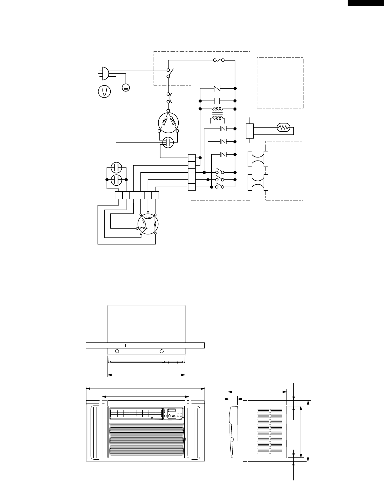
WIRING DIAGRAM
AF-R125CX
POWER SUPPLY CORD
115V 60Hz
NON RIBBED
GR
IN
OUT
OVERLOAD
PROTECTOR
C
R
RE
RIBBED
COMPRESSOR
MOTOR
RUNNING
CAPACITOR
370V 50µF
FAN MOTOR
CAPACITOR
250V 6µF x 2
BL
BK
GY
RE
OR
BL
BK
123654
BL
THERMAL
BK
GYREOR
WH
CONNECTOR
WH
M
H
L
FAN MOTOR
PROTECTOR
BK
BL
M.C
A.C
MRY
BK
BK
S
WH
GY
8
7
1
3
5
3A 125V
FU1
CONTROL
BOAD UNIT
NR
C1
CNR1
CNR2
CNR3
BCN1
TR
RY1
RY2
RY3
WIRE COLOR
BK
BL
RE
WH
GR
GY
OR
THERMISTOR
CN1
(
ROOM TEMP
YELLOW TH1
CN2
CN3
: BLACK
: BLUE
: RED
: WHITE
: GREEN
: GRAY
: ORANGE
)
BCN2
DISPLAY
BOARD
UNIT
BCN3
Figure W-1
EXTERNAL DIMENSIONS
22-1/16"
38-19/32"
27-5/32"
24-5/16"
5-3/16"
1-3/8"
14-3/4"
16-23/32"
19/32"
3
Page 4

AF-R125CX
UNIT
OPERATION INSTRUCTIONS
5
6
4
7
3
2
1
1
Front panel
2 Air inlet (Indoor side)
3 Louvers
4 Air inlet (Outdoor side)
5 Exhaust lever
6 Control panel
CONTROL PANEL
1 2 3
8
9
10
11
7 Cabinet
8 Air outlet (Outdoor side)
9 Air inlet (Outdoor side)
10
Filter (Pull the filter handle to the right to remove.)
11
Filter handle
12
Power cord
12
HIGH COOL
MED COOL
LOW COOL
FAN ONLY
SELECTOR
TIMER
ON/OFF
4 5 6 7 8 9
1 Selector indicator
2 Receiver window for remove control
signal
3 Display
4 SELECTOR pad
5 TIMER ON/OFF pad
6 TIMER indicator
TEMP
F
hr
ENERGY
SAVER
POWER
ON/OFF
10 11
7 TEMPERATURE setting pad
Lower temp.
Raise temp.
8 ENEGRY SAVER pad
9 ENEGRY SAVER indicator
10
POWER ON/OFF pad
11
POWER indicator
4
Page 5

AF-R125CX
REPLACEMENT PARTS LIST
REF. NO. PART NO. DESCRIPTION Q'TY CODE
CABINET AND UNIT PARTS
1- 1 CMOTLA895JBEZ Fan motor 1 BN
1- 2 DCHS-A440JBTA Base pan ass’y 1 BC
1- 3 DCAB-A094JBTA Cabinet ass’y 1 BF
1- 4 PSEL-B150JBE0 Cabinet seal 2 AD
1- 5 HPNLCA770JBFB Control panel 1 AF
1- 6 PSEL-C059JBEZ Evaporator insulator 1 AD
1- 7 LANG-A459JBWZ Conecting stay 1 AC
1- 8 LANG-A355JBTA Top inst. Angle 1 AP
1- 9 LHLD-A482JBFZ Thermistor holder 1 AE
1-10 CLEV-A039JBKZ Damper ass’y 1 AG
1-11 NFANPA092JBFZ Propeller fan 1 AV
1-12 NFANSA030JBFZ Centrifugal fan 1 AU
1-13 PFILMA116JBEC Air filter 1 AN
1-14 PFPFPB466JBE0 Insulator 2 AC
1-15 PKESPA082JBTA Condenser shroud 1 AV
1-16 PKESPA083JBFA Orifice 1AQ
1-17 LBND-A046JBE0 Wire fixing band 1 AE
1-18 LCOV-A002JBF0 Shroud cover 1 AM
1-19 PCOV-A320JBP0 Motor cover 1 AC
1-20 PSEL-C057JBEZ Tube insulator 1 AD
1-21 LANG-A356JBTA Bottom inst. angle 1 AE
1-22 PSKR-A207JBFA Bulkhead 1 BA
1-23 PSRA-A120JBFZ Drain tray 1 AE
1-24 TLAB-C276JBRZ Energy card 1 AC
1-25 TSPC-E154JBRZ Name badge 1 AC
1-26 GWAKPA136JBFC Louver duct 1 AL
1-27 GWAKPA135JBFC Front panel 1 AX
1-28 TLABBA110JBRA SHARP badge 1 AB
1-29 LANGAA038JBFB Left closure frame 1 AK
1-30 LANGAA039JBFB Right closure frame 1 AK
1-31 PPLTPA013JBFB Closure 2AL
1-32 PSPRCA010JBE0 Spring 1AD
1-33 TLABKA564JBE0 Number card 1 AC
1-34 PFPFPB446JBE0 Insulator 1 AC
1-35 CWAK-C132JBKZ Front panel ass’y 1 AZ
1-36 MJNTPA074JBFC Louver link 2 AC
1-37 MLOV-A252JBFC Vertical louver A 4 AC
1-38 MLOV-A253JBFC Vertical louver B 2 AC
1-39 PSEL-B360JBE0 Cabinet insulator 1 AB
1-40 PSEL-C064JBEZ Drain tray insulator 1 AC
1-41 PSEL-B361JBE0 Cabinet insulator 2 AE
1-42 PSEL-B367JBE0 Cabinet insulator 2 AC
1-43 PSEL-B516JBE0 Base pan insulator 2 AC
1-44 PFPFPB443JBE0 Insulator 1 AC
1-45 PSEL-C063JBEZ Bulkhead insulator 1 AC
1-46 PSEL-B519JBE0 Angle insulator 1 AD
1-47 PSEL-C056JBEZ Motor seal 1 AE
1-48 LHLDW0367JBE0 Wire holder 1 AA
1-49 LHLDW0368JBE0 Wire holder 1 AA
1-50 PFPFPB528JBE0 Panel insulator 1 AD
1-51 PSEL-A432JBE0 Damper insulator 1 AC
1-52 PFPFPB611JBE0 Insulator 1 AG
1-53 PSEL-B532JBE0 Damper insulator 1 AB
1-54 PSEL-B394JBE0 Panel insulator 1 AB
1-55 PSEL-B560JBE0 Damper insulator 1 AB
1-56 LANG-A507JBWZ Fan motor angle 1 AH
1-57 HPNLCA828JBEA Decoration panel 1 AD
1-58 PSEL-B366JBE0 Panel insulator 1 AD
1-59 PSEL-C104JBEZ Insulator 1 AB
1-60 PSEL-C105JBEZ Cabinet insulator 1 AE
1-61 LHLDW0363JBE0 Wire holder 1 AA
1-62 PSHE-A191JBEZ Sheet 1AE
1-63 LHLD-A356JBE0 Wire holder 1 AE
CONTROL BOX PARTS
2- 1 LBNDKA096JBWZ Capacitor clamp 1 AC
2- 2 LPLTMA128JBW0 Control box cover 1 AK
2- 3 DPLT-A047JBW0 Cont. box angle ass’y 1 AS
5
Page 6

AF-R125CX
REF. NO. PART NO. DESCRIPTION Q'TY CODE
2- 4 QACC-A263JBZZ Power supply cord 1 AT
2- 5 RH-HXA011JBZZ Thermistor 1 AL
2- 6 QW-VZD104JBE0 Lead wire 1 AD
2- 7 QW-IZA036JBZZ Lead wire 1 AS
2- 8 RC-HZA256JBE0 Fan motor capacitor 2 AM
2- 9 RC-HZA407JBZZ Running capacitor 1 AY
2-10 TLABCB377JBRZ Wiring diagram 1 AC
2-11 DPWBFA193JBKZ Control board unit 1 BC
2-12 PSPA-A084JBE0 Spacer 2AC
2-13 PSPA-A085JBE0 Spacer 1AC
2-14 QFS-AA048JBE0 Fuse 1AB
2-15 LBND-A042JBE0 Wire fixing band 4 AC
CYCLE PARTS
3- 1 PCMPRA359JBEZ Compressor 1 CC
3- 2 PPIPCF655JB1Z Discharge tube 1 AR
3- 3 PPIPCF654JB1Z Suction tube 1 AS
3- 4 RHOG-A198JBZZ Overload relay 1 AT
3- 5 DCON-A167JBKZ Condenser ass’y 1 BT
3- 6 PEVA-A424JBEZ Evaporator 1 BQ
3- 7 GLEG-A105JBE0 Compressor cushion 3 BQ
3- 8 LPLTMA114JBW0 Condenser stay 2 AH
3- 9 PCOV-A321JBE0 Terminal cover 1 AR
3-10 PSEL-A971JBE0 Terminal gasket 1 AN
3-11 DCPY-A234JBKZ Capillary tube ass’y 1 AW
3-12 MSPR-A129JBE0 Cycle spring 1 AD
3-13 PGUM-0034JBE0 Damper rubber 1 AF
3-14 MSPR-A136JBE0 Protector spring 1 AF
ACCESSORY PARTS
4- 1 TINSEA320JBRZ Operation manual 1 AD
4- 2 PSEL-A349JBE0 Window insulator 1 AE
4- 3 PSEL-A350JBE0 Window insulator 1 AD
4- 4 PSEL-B365JBE0 Window insulator 1 AD
4- 5 TCAD-A351JBEZ Consummer card 1 AB
4- 6 DX-BZA027JBK0 Screws kit 1 AE
4- 7 CRMC-A526JBEZ Remote control 1 AT
4- 8 LHLD-A389JBFB Controller holder 1 AE
4- 9 SSAKAA017YDE0 Bag 1AC
4-10 UBATUA027JBE0 Battery pack 1 AE
PACKING PARTS
5- 1 CPADBA688YDK0 Top pad ass’y 1 AL
5- 2 CPADBA009JBK0 Bottom pad ass’y 1 AT
5- 3 SPAKCB066JBEZ Packing case 1 AY
5- 4 SSAKHA314YDE0 Protect 1AD
5- 5 PPAK-A007JBE0 Inner packing 1 AG
5- 6 TLABMA333JBRZ Color label 1 AC
5- 7 SSAKAA053YDE0 Bag 1AB
5- 8 TLABMA309JBRZ Feature card 1 AB
SCREWS AND NUTS
6- 1 XTTSD40P12000 Tapping screw 22 AA
6- 2 LX-BZA236JBE0 Special screw 1 AC
6- 3 XHTSD40P08000 Tap tight screw 8 AA
6- 4 LX-NZA136JBE0 Special nut 1 AL
6- 5 LX-HZA001JBE0 Special screw 6 AB
6- 6 XCTSD40P10000 Tapping screw 19 AA
6- 7 LX-NZA074JBE0 Special nut 1 AB
6- 8 LX-NZA028JBE0 Special nut 3 AB
6- 9 XTPSD40P08000 Tapping screw 3 AA
6-10 XCTSD40P06000 Tapping screw 16 AA
6-11 XBPSD40P12J00 Machine screw 2 AB
6-12 LX-CZA038WRE0 Special screw 6 AA
6-13 XHTSD40P10000 Tap tight screw 2 AA
6-14 XTPSD40P12000 Tapping screw 2 AA
HOW TO ORDER REPLACEMENT PARTS
To have your order filled promptly and correctly, please furnish the following information.
1. MODEL NUMBER 2. REF. NO.
3. PART NO. 4. DESCRIPTION
6
Page 7

7
AF-R125CX
5-4
6-6
1-38
1-38
1-37
1-37
1-36
1-27
1-10
1-55
1-53
1-51
1-16
1-12
1-22
1-1
1-7
1-39
1-49
1-8
1-28
1-3
1-25
1-2
1-23
1-11
1-21
1-48
1-35
1-26
1-32
1-50
1-58
6-2
5-8
6-1
6-12
1-14
1-14
1-4
1-4
6-10
6-1
6-1
1-63
6-6
6-1
6-1
6-12
6-1
6-12
6-6
6-6
6-12
6-6
6-5
6-5
6-5
6-6
1-18
1-15
6-6
6-6
6-12
6-7
6-1
6-5
6-6
1-19
6-6
6-5
6-1
1-20
1-45
1-59
1-34
1-52
1-60
1-13
1-62
1-54
1-6
1-17
1-47
1-40
1-43
1-43
1-46
1-42
1-41
1-41
4-6
4-5
4-7
4-8
4-4
5-5
5-3
1-33
1-24
5-6
5-2
5-1
5-7
2-4
1-30
4-2
4-3
4-1
4-10
4-9
1-29
1-31
1-42
1-56
1-56
6
45
1
2
3
6
45
1
2
3
A
B
C
D
E
F
G
H
A
B
C
D
E
F
G
H
CABINET PARTS
Page 8

AF-R125CX
1
2
3
45
6
CONTROL BOX PARTS
A
6-3
6-3
6-3
2-10
2-2
2-14
B
1-5
2-11
6-9
6-3
2-1
1-57
C
2-3
6-14
D
2-12
2-13
2-6
6-3
2-4
6-11
6-1
6-13
6-3
2-8
2-9
A
B
2-7
C
2-4
2-15
D
CYCLE PARTS
6-4
2-5
3-9
3-10
3-12
3-1
3-14
3-4
2-7
1-44
6-10
3-5
3-2
3-8
6-10
3-3
6-10
6-1
3-7
6-8
6-1
45
E
F
G
H
6
E
F
3-11
3-13
G
6-1
3-6
2-6
H
6-3
1-61
6-1
1-9
1
2
3
8
2002 SHARP CORP. (2S1.600E) Printed in U.S.A.
 Loading...