

Page 1
ROOM AIR CONDITIONER
AF-A18CE
INSTALLATION AND OPERATION
MANUAL
КОМНАТНЫЙ КОНДИЦИОНЕР
РУКОВОДСТВО ПО УСТАНОВКЕ
И ЭКСПЛУАТАЦИИ
CONTENTS
PART NAMES AND DIMENSIONS ...... E-1
INSTALLATION INSTRUCTIONS ........ E-1
OPERATION INSTRUCTIONS ............. E-6
MODES OF OPERATION..................... E-7
CLEANING AND MAINTENANCE ....... E-9
BEFORE CALLING FOR SERVlCE ..... E-10
AF-A24CE
PAGE
ENGLISH
СОДЕРЖАНИЕ
НАИМЕНОВАНИЕ ЧАСТЕЙ
И РАЗМЕРЫ ........................................ R-1
ИНСТРУКЦИИ ПО УСТАНОВКЕ ....... R-1
ИНСТРУКЦИИ ПО ЭКСПЛУАТАЦИИ ...
РЕЖИМЫ РАБОТЫ ............................ R-7
ОЧИСТКА И УХОД.............................. R-9
ПРЕЖДЕ ЧЕМ ОБРАЩАТЬСЯ
В СЛУЖБУ СЕРВИСНОГО
ОБСЛУЖИВАНИЯ .............................. R-10
This INSTALLATION AND OPERATION MANUAL explains the proper use of your new SHARP Air
Conditioner. Read these instructions carefully before installing or operating your air conditioner. The
INSTALLATION AND OPERATION MANUAL should be kept in a safe place for handy reference.
В настоящем РУКОВОДСТВЕ ПО УСТАНОВКЕ И ЭКСПЛУАТАЦИИ объясняется, как правильно
пользоваться Вашим новым кондиционером SHARP. Пожалуйста, перед установкой и
эксплуатацией Вашего кондиционера внимательно прочтите эти инструкции. Это РУКОВОДСТВО
следует хранить в удобном месте для будущих консультаций.
СТРАНИЦА
R-6
РУССКИЙ
Page 2

Page 3
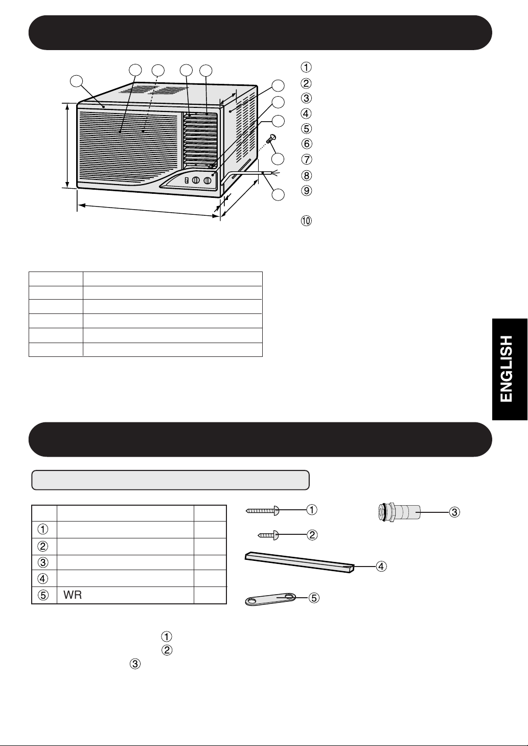
PART NAMES AND DIMENSIONS
1
B
DIMENSIONS
MODEL
A (mm)
B (mm)
C (mm)
D (mm)
E (mm)
2
A
AF-A18CE, AF-A24CE
4
3
5
D
660
425
729 (center 740)
294
40 (center 51)
Front panel
6
7
8
9
E
C
10
Grille
Air filter (behind the grille)
Up/Down air flow adjustment louvers
Left/Right air flow adjustment louvers
Cabinet
Ventilation lever
Control panel
Stopper screws
(on left and right)
Power cord
We reserve the right to change the materials and specifications without notice.
INSTALLATION INSTRUCTIONS
ITEMS PACKED WITH THIS UNIT
Accessories
GOLD SCREW (2.5cm/1")
GOLD SCREW (1.2cm/0.5")
DRAIN JOINT
BOTTOM GASKET
WRENCH
The long GOLD SCREW ( ) is used to secure the cabinet to the mounting frame.
The short GOLD SCREW( ) is used to secure the front panel to the unit.
The DRAIN JOINT ( ) is attached to the outlet on the back of the unit.
Cut off the blockage of the drain joint, if outside water drainage is necessary in high humidity
district, or if you do not prefer the splashing sound of the non-drain function.
See page E-3 for detail installation instructions.
Q'ty
8
1
1
1
1
ENGLISH
E-1
Page 4
INSTALLATION INSTRUCTIONS
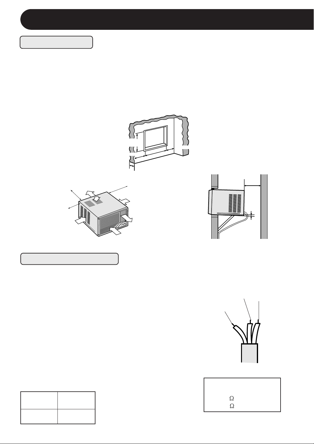
LOCATION
The appliance shall be installed in accordance with national wiring regulations.
Improper connection may cause the power cord and electrical outlet to overheat or fire.
Install the air conditioner to the opening dimensions shown below.
Never install the unit where any of the air inlet is blocked.
The air conditioner should be installed with a strong external support to minimize noise and
vibration, and for the purpose of safe installation, repair, replacement and secure positioning.
Avoid installing the air conditioner where it is exposed to direct sunlight.
43.5~44.5 cm
More than 40cm(16")
Air outlet
(17 1/8"~17 1/2")
More than 20 cm
(8")
More than 20cm(8")
67~68 cm
(26 3/8"
8~20 cm(3"~8")
~26 3/4"
More than 20 cm(8")
)
More than 40cm
(16")
Air inlet
More than 20cm(8")
Air inlet
Air inlet
Air outlet
Air inlet
POWER CABLING
GROUNDING
WARNING : THIS APPLIANCE MUST BE
GROUNDED.
Fit a disconnect switch, having a contact separation of
at least 3mm in all poles, to the electricity power line.
Connect the brown wire of the power supply cord to the
live terminal, and the grounding wire (green and yellow)
to the grounding terminal of the electrical outlet. The
remaining wire should be connected to the neutral
terminal of the electrical outlet.
FUSE
For safe, trouble free operation, connect the power
cord of the unit to a properly rated independent circuit
with a time delay fuse or a circuit breaker. See chart
for proper amp ratings for each model.
AF-A18CE
AF-A24CE
20 amp.
25 amp.
About 1cm
(3/8")
Grounding wire
(green&yellow)
Live
(brown)
Neutral
(blue)
Maximum Permissible
System Impedance
0.18 ( AF-A18CE )
0.13 ( AF-A24CE )
E-2
Page 5

INSTALLATION INSTRUCTIONS
INSTALLATION
WARNING:
Turn off and disconnect the unit before working.
Remove the front panel by pulling the
1
front panel at the lower corners towards
you about 3 cm (1" ). Next lift it up and
pull it towards you.
(Fig.1)
(1)
Unscrew the 2 stopper screws at the
2
back of the cabinet (Fig.2).
Front panel
Fig.1
Angle
Unscrew the stopper screw from the
(2)
angle at the front of the chassis.
Keep the screw and angle as they
will be used later in Step 6.
Slide the chassis out from the cabinet
(3)
by pulling on the hand hold located
at the bottom center of the chassis.
(Fig.2)
Remove the 3 fixing nuts and the fixing
angles from the compressor.(Fig.3)
3
Some models may not be equipped
with the fixing angles. These are for the
purpose of transportation only. Keep
them in a handy place in case of relocation.
ENGLISH
Cabinet
Chassis
Fig.2
Wrench
Compressor
Fixing nut
Fixing angle
E-3
3 positions
Rubber
Fig.3
Page 6

INSTALLATION INSTRUCTIONS
Attach the drain joint provided with your
4
air conditioner accessory to the back of
the chassis for convenience when
outside drainage becomes necessary.
(Fig.4)
When drainage is necessary
If outside water drainage is necessary in
high humidity district, or if you do not
prefer the splashing sound of the nondrain function, cut off the blockage of the
drain joint .(Fig.5)
A hose of an appropriate length may be
attached to drain outlet water.
1
3
Drain joint
2
Drain joint
4
Fig.4
Blockage
Fig.5
5
Install the cabinet into the installation
(1)
opening.
(2)
Secure the cabinet to the mounting
frame using 8 long gold
screws(2.5cm/1"). (Fig.6)
WARNING:
At this step, make sure the cabinet is
inclined approximately 1cm (3/8") to
the back (Fig.7).
If the cabinet is not properly inclined,
the water collected in the bottom tray
during operation will not drain properly and may flow into the room
where the air conditioner is installed.
Attach the bottom gasket to the gap
(3)
between the mounting frame and the
unit to seal outside air. (Fig.6)
Cabinet
mounting
frame
Bottom gasket
cabinet
incline backwards
about 1cm (3/8")
Fig.6
More than
40cm (16")
Fig.7
E-4
Page 7

INSTALLATION INSTRUCTIONS
Slide the chassis back into the
cabinet.
6
Secure the chassis to the cabinet
using the screw and angle removed
in Step 2. Push the angle into the
gap between the chassis and the
cabinet. Slide the angle to the right
until the holes meet, and screw it on
to the chassis. (Fig.8)
Replace the front panel. (Fig.9)
(1)
7
Slide the crank shaft into the
opening of the louver link at the
back of the front panel. (Fig.10)
(2)
Remove the grille (Fig.11) and
the air filter (Fig.12) from the front
panel.
Secure the front panel with one
short gold screw(1.2cm/0.5")
(Fig.12) and replace the air filter
and the grille.
Angle
Hole
Chassis
Crank shaft
Cabinet
Fig.8
Fig.9
ENGLISH
Grille
Fig.11
Air filter
E-5
Front panel back view
Louver link
Fig.10
Front panel
Fig.12
Page 8

OPERATION INSTRUCTIONS
OPERATION INSTRUCTIONS
PRECAUTIONS
POWER CORD REPLACEMENT
WARNING: For replacement, use only the manufacturer specified power cord.
Replacemant should be conducted by a qualified technician or a serviceman. Consult your dealer
for detailed information concerning replacement of the power cord.
WAIT FOR 3 MINUTES BEFORE RESTARTING THE COOLING OPERATION
Whenever you turn the air conditioner OFF, wait for at least three (3) minutes before restarting
the unit.
If you restart the air conditioner within three minutes, a protective device in the unit may cause
the air conditioner to shut off. This protective device will prevent cooling operation for about 5
minutes.
IF A POWER FAILURE OCCURS DURING OPERATION, MAKE SURE TO TURN OFF THE AIR
CONDITIONER
After resumption of power supply, restart the air conditioner . If the power was off for less
than three minutes, make sure to wait for at least three minutes before restarting the unit.
If the air conditioner is not turned off during a power failure, the resumption of power supply
will cause excessive voltage. The air conditioner will be over-loaded and will not operate for
about 5 minutes.
TO STOP THE UNIT, TURN THE SELECTOR KNOB TO THE "OFF" POSITION.
ALWAYS USE A FUSE WITH THE PROPER AMP RATING
Never use wire, pins or anything other than the proper fuse. The product may be damaged and
fire or other hazards may be resulted. In replacing a blown fuse, or if there is the problem of
constant fuse blowing, contact your dealer or our service center.
VENTILATE THE ROOM PERIODICALLY DURING USE, ESPECIALLY IF GAS APPLIANCES ARE
USED.
NOTES ON OPERATION
POWER SUPPLY VOLTAGE
If the power supplied to the unit is not within plus / minus 10 % of the specified rating, the unit may
not function and the fuse may blow.
OPERATING TEMPERATURE RANGE
INDOOR TEMP. OUTDOOR TEMP.
COOLING
upper limit
lower limit
D.B. = Dry-bulb W.B. = Wet-bulb
NOISE LEVEL
32˚C D.B. 43˚C D.B.
23˚C W.B. -
21˚C D.B. 21˚C D.B.
15˚C W.B. -
As the surrounding environment is comparatively silent at night, noise from the air conditioner
may be louder at night than in the day time. If you feel that noise of the air conditioner is too loud,
switch the "SELECTOR" knob to the "LOW COOL" position.
WATER IN THE BOTTOM TRAY
Water will be collected at the bottom tray of the unit. This is normal condition. Water condenses
on the evaporator coil in the front part of the unit and is channeled to the rear where it is picked
up by the condenser fan. The water is blown onto the condensor coil fins, this creates a
"splashing" sound which is normal. When the tray is filled up with water, excessive water will be
drained outside through a grooved channel in the tray.
E-6
A built-in protective device might prevent the unit from operating when used
out of this range.
Condensation might form on the air outlet when the unit operates continuously
in the COOL mode when the humidity is
over 80 percent.
Page 9

MODES OF OPERATION
PART NAMES
WAIT THREE MINUTES BEFORE RESTARTING
COOLER
FAN
OFF
AUTO SWING THERMOSTAT SELECTOR
1 2 3 4
Control panel
Auto swing switch
Thermostat knob
LOW
COOL
MED
COOL
HIGH
COOL
5
Selector knob
Ventilation lever
SELECTOR KNOB
Use to select the desired mode.
OFF
FAN
Both the fan and cooling operation are off.
This setting can be used to circulate air whenever cooling is not desirable.
The air conditioner will perform fan operation at medium speed.
LOW
Cooling for sleeping comfort with low fan speed.
COOL
MED
COOL
HIGH
COOL
Fan operates at medium speed; cooling power at medium.
Fan and cooling at maximum power.
NOTE FOR COOLING OPERATION
When operating the air conditioner under extremely
high outdoor temperature, set the air conditioner as
shown in the chart at right for efficient performance.
THERMOSTAT
SELECTOR : HIGH COOL
VENTILATION : LEFT (CLOSED) position
: 8, 9 or 10
ENGLISH
E-7
Page 10

MODES OF OPERATION
THERMOSTAT KNOB
Use to adjust the desired room temperature setting.
The air conditioner will automatically maintain the room temperature according to the
THERMOSTAT setting. The higher the numbers, the cooler the room temperature becomes.
Experiments may be needed in order to find out the most suitable setting.
AUTO SWING SWITCH
Use to activate automatic louver movement during LOW COOL, MED COOL and
HIGH COOL.
Adjust the louvers to change the direction of air flow for uniform and efficient cooling of the
room. Set the AUTO SWING switch ON ( ), and the Left/Right air flow adjustment louvers
will swing continuously to provide better circulation of cool air. The louvers will be stopped at
the position when the switch is turned off. You can also use the switch to adjust the Left/Right
air flow adjustment louvers to the desired position. Never attempt to move the Left/Right air
flow adjustment louvers manually, or manually force the louver movement to stop during
swing operation.
The AUTO SWING switch will not activate the louvers when the SELECTOR KNOB is set to
FAN.
UP/DOWN AIR FLOW ADJUSTMENT
Airflow direction can be adjusted by moving the airflow adjustment louvers upward or downward. To avoid condensation on the louvers, please do not adjust these louvers to extremely
downward position during LOW COOL, MED COOL and HIGH COOL operation modes for a
long time.
VENTILATION LEVER
If air in your room is stale, set the VENTILATION lever to the RIGHT (OPEN) position. This
will remove stale air from the room. The VENTILATION lever should normally be kept in the
LEFT (CLOSED) position during cooling operation for maximum cooling effect.
Up/Down air flow
adjustment louvers
Left/Right air flow
adjustment louvers
(Auto Swing)
Ventilation lever
E-8
CLOSED OPEN
Page 11

CLEANING AND MAINTENANCE
WARNING : Turn off the unit before performing any cleaning or maintenance.
CLEANING THE FILTER
If the filter is clogged with dust, the amount of air flow will be reduced, resulting in poor
cooling performance. The filter should be cleaned for every 10 days. At the beginning of
every cooling season or if the air conditioner has not been used for a long period, clean the
filter before starting to operate the unit.
REMOVE THE AIR FILTER
1.
Remove the grille by sliding it to the left until
it stops and then pull it towards you. Next lift
and unhook the bottom of the air filter and
remove it.
2.
CLEAN THE FILTER
To remove dust from the filter, use a
vacuum cleaner or wash it with water.
If the filter is very dirty, wash it with
detergent and rinse carefully with water.
Dry the filter with a soft cloth. Do not expose
the filter to heat or dry it under direct
sunlight.
Grille
Air filter
3.
RE-INSTALL THE FILTER
Fit the top hooks, and then hook the bottom
of the air filter. Replace the grille. Never
operate the unit without installing the filter or
the grille. It may be resulted in serious
damage to the unit.
Air filter
Air filter
CLEANING OF THE FRONT PANEL,GRILLE AND CABINET
To clean the front panel, grille and cabinet, wipe with a soft, dry cloth or with a cloth
moistened with a mild soap. Rinse carefully by wiping with a damp cloth and dry
completely.
Avoid splashing the unit with water. Excessive water will affect electrical insulation
and fire may be resulted during operation.
Never use erosive chemicals or abrasive cleaners on any part of the unit. To avoid
damaging the unit, do not use hot water of over 50°C when cleaning.
OILING OF THE COMPRESSOR AND FAN MOTOR IS UNNECESSARY
ENGLISH
The compressor is permanently lubricated and is hermetically sealed. The fan motor
is lifetime sealed and does not require oiling.
E-9
Page 12

BEFORE CALLING FOR SERVlCE
IF YOUR AIR CONDITIONER DOES NOT OPERATE PROPERLY, PLEASE CHECK
THE FOLLOWING ITEMS BEFORE CALLING FOR SERVICE.
AIR CONDITIONER DOES NOT OPERATE AT ALL
• Is the power cord loosened or disconnected?
• Is the fuse blown or has the circuit breaker been tripped?
• Did you restart the unit within 3 minutes after power failure? If the power was off for less
than 3 minutes, and you restart the air conditioner within 3 minutes, a protective device
may cause the air conditioner to shut off, preventing cooling operation for about 5
minutes.
AIR CONDITIONER DOES NOT COOL PROPERLY
• Is the SELECTOR set to FAN?
Cooling will not be conducted in FAN setting. Change the SELECTOR setting to LOW
COOL, MED COOL or HIGH COOL.
• Is the filter covered with heavy dirt?
A dirty filter can cause the cooling coils to get frozen. If this happens, clean the filter and
replace it. Run the air conditioner with the FAN setting until defrostation.
• Is the THERMOSTAT set properly?
If your room is too warm, adjust the THERMOSTAT knob to a higher cooling setting.
If your room is too cool, adjust the THERMOSTAT knob to a lower cooling setting.
• Is the VENTILATION lever set in the RIGHT (OPEN) position?
The lever should be set in the LEFT (CLOSED) position during cooling operation.
• Are the windows exposed to direct sunlight?
Close curtains or blinds to minimize the heat in the room.
• Are the windows or doors open?
Close all windows and doors for maximum cooling effect.
LEFT / RIGHT AIR FLOW ADJUSTMENT LOUVERS DO NOT SWING
• Is the crank shaft fit properly into the louver link?
Remove the front panel, and replace it again. Make sure to slide the crank shaft into the
opening of the louver link at the back of the front panel. (See page E-5, step7-(1))
• Is the SELECTOR set to FAN? The auto swing louver can be activated only at LOW
COOL, MED COOL and HIGH COOL settings.
FOLLOWINGS ARE NORMAL CONDITIONS OF THIS AIR CONDITIONER
SOUNDS
• The sound of the compressor may seem rather loud for 2 to 3 minutes when the unit is
turned on. This is the sound of the compressor's start-up and is normal for this unit.
• A soft swishing noise can be heard immediately after the unit is turned on or off, and also
during operation. This is the sound of the refrigerant flowing inside the unit.
ODORS
• Carpet and furniture odors may enter the unit and be sent out from the unit.
E-10
Page 13

TINSEA329JBRZ 02CO
TL
1
SHARP ELECTRONICS CORPORATION
SHARP CORPORATION
Osaka, Japan
Printed in Thailand
 Loading...